Embed Size (px)
Citation preview
Evaluating the Effectiveness of Mixed RealitySimulations for Developing UAV Systems
Ian Yen-Hung Chen1, Bruce MacDonald1, and Burkhard Wunsche2
1 Dept. of Electrical and Computer Engineering,University of Auckland, New Zealand
{i.chen, b.macdonald}@auckland.ac.nz2 Dept. of Computer Science,
University of Auckland, New [email protected]
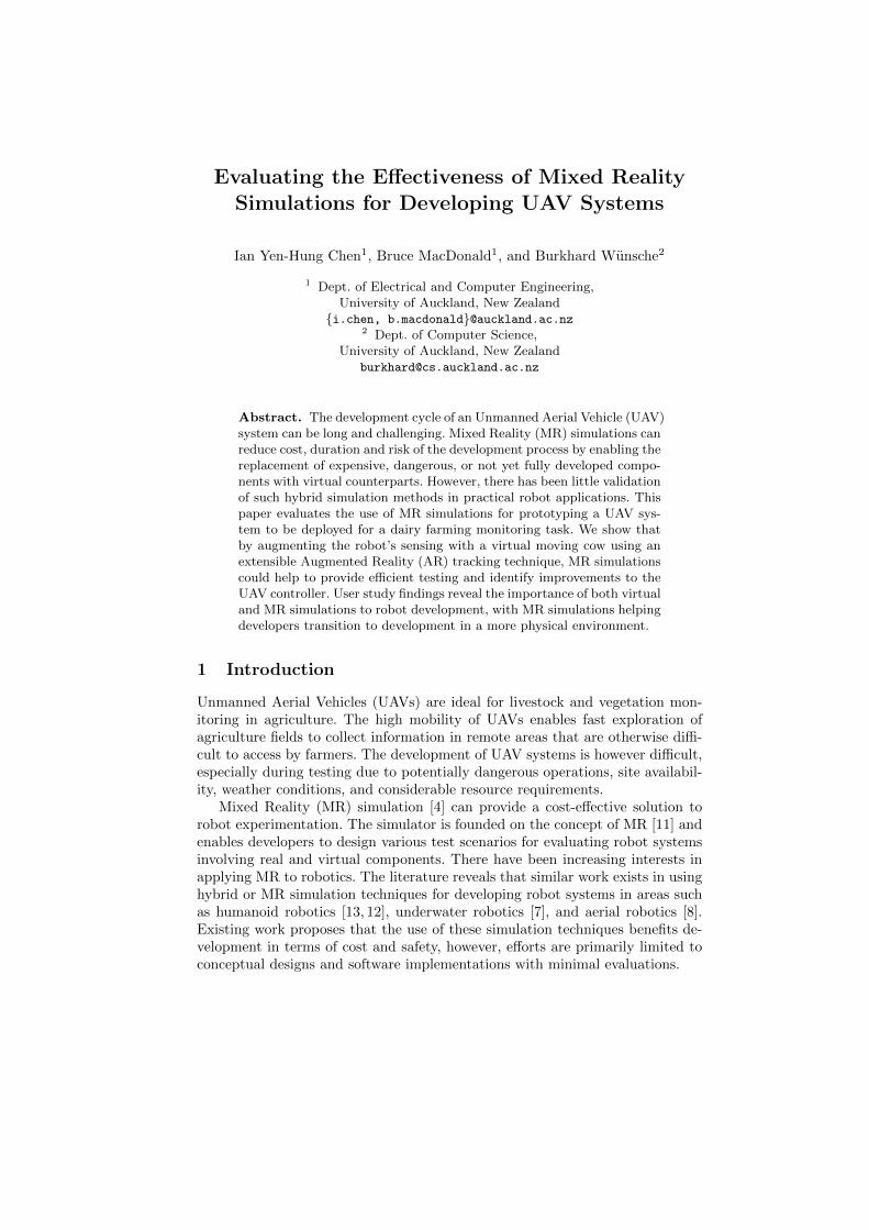
Abstract. The development cycle of an Unmanned Aerial Vehicle (UAV)system can be long and challenging. Mixed Reality (MR) simulations canreduce cost, duration and risk of the development process by enabling thereplacement of expensive, dangerous, or not yet fully developed compo-nents with virtual counterparts. However, there has been little validationof such hybrid simulation methods in practical robot applications. Thispaper evaluates the use of MR simulations for prototyping a UAV sys-tem to be deployed for a dairy farming monitoring task. We show thatby augmenting the robot’s sensing with a virtual moving cow using anextensible Augmented Reality (AR) tracking technique, MR simulationscould help to provide efficient testing and identify improvements to theUAV controller. User study findings reveal the importance of both virtualand MR simulations to robot development, with MR simulations helpingdevelopers transition to development in a more physical environment.
1 Introduction
Unmanned Aerial Vehicles (UAVs) are ideal for livestock and vegetation mon-itoring in agriculture. The high mobility of UAVs enables fast exploration ofagriculture fields to collect information in remote areas that are otherwise diffi-cult to access by farmers. The development of UAV systems is however difficult,especially during testing due to potentially dangerous operations, site availabil-ity, weather conditions, and considerable resource requirements.
Mixed Reality (MR) simulation [4] can provide a cost-effective solution torobot experimentation. The simulator is founded on the concept of MR [11] andenables developers to design various test scenarios for evaluating robot systemsinvolving real and virtual components. There have been increasing interests inapplying MR to robotics. The literature reveals that similar work exists in usinghybrid or MR simulation techniques for developing robot systems in areas suchas humanoid robotics [13, 12], underwater robotics [7], and aerial robotics [8].Existing work proposes that the use of these simulation techniques benefits de-velopment in terms of cost and safety, however, efforts are primarily limited toconceptual designs and software implementations with minimal evaluations.
2 Ian Chen et al.
This paper presents a case study evaluation of MR simulations for proto-typing a vision-based UAV system to be deployed for a cow monitoring task inagriculture. There are novel challenges in creating MR simulations for this task.We assess our MR robot simulator’s [4] capability to a) provide robot developersa safe and efficient way of creating test scenarios for this high-risk operation,and b) accurately augment the robot’s visual sensing with virtual inputs underthe erratic motion of the UAV platform. A user study is also conducted to exam-ine the robot developers’ use of MR simulations for prototyping UAVs, and ananalysis of its results forms one of the main contributions of this paper. Similaruser studies have been presented such as in [6], but the focus is on the visuali-sation aspects of MR for robot development. Our previous work [5] investigatedthe user’s perception of the MR simulation technology and its visual interfacesin a robot operation task, which did not involve any implementations. In com-parison, this paper describes a user study that identifies how MR simulationscan help robot programmers in implementing a robot software component, thedevelopment stages and tasks which MR simulations are suitable for, and howthey compare with virtual simulations.
The remainder of the paper is organised as follows. Section 2 gives backgroundon the cow monitoring project. Section 3 describes the MR simulation createdfor testing the UAV prototype. Section 4 presents evaluation results. Section 5describes the user study and its findings.
2 Cow Monitoring Project Background
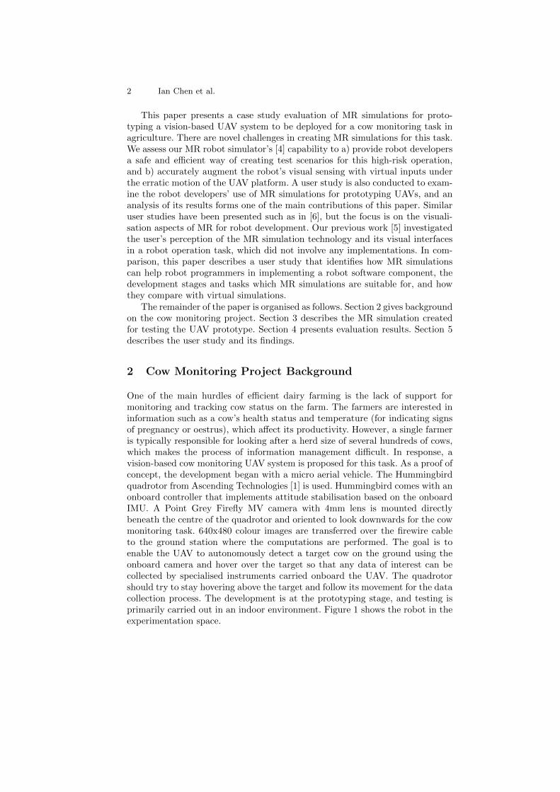
One of the main hurdles of efficient dairy farming is the lack of support formonitoring and tracking cow status on the farm. The farmers are interested ininformation such as a cow’s health status and temperature (for indicating signsof pregnancy or oestrus), which affect its productivity. However, a single farmeris typically responsible for looking after a herd size of several hundreds of cows,which makes the process of information management difficult. In response, avision-based cow monitoring UAV system is proposed for this task. As a proof ofconcept, the development began with a micro aerial vehicle. The Hummingbirdquadrotor from Ascending Technologies [1] is used. Hummingbird comes with anonboard controller that implements attitude stabilisation based on the onboardIMU. A Point Grey Firefly MV camera with 4mm lens is mounted directlybeneath the centre of the quadrotor and oriented to look downwards for the cowmonitoring task. 640x480 colour images are transferred over the firewire cableto the ground station where the computations are performed. The goal is toenable the UAV to autonomously detect a target cow on the ground using theonboard camera and hover over the target so that any data of interest can becollected by specialised instruments carried onboard the UAV. The quadrotorshould try to stay hovering above the target and follow its movement for the datacollection process. The development is at the prototyping stage, and testing isprimarily carried out in an indoor environment. Figure 1 shows the robot in theexperimentation space.
Title Suppressed Due to Excessive Length 3
Fig. 1. Indoor UAV system test setup ona mock-up agricultural environment. Theexperimental setup is not to scale.
UAV PlatformGround Control Station
Client Programs MR Simulation
MRCameraObject
Detector
Object Follower
AscTec Hummingbird
AscTec Autopilot
MRPosition
Position Control
Camera
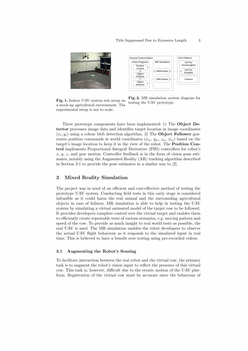
Fig. 2. MR simulation system diagram fortesting the UAV prototype.
Three prototype components have been implemented: 1) The Object De-tector processes image data and identifies target location in image coordinates(xi, yi) using a colour blob detection algorithm. 2) The Object Follower gen-erates position commands in world coordinates (xw, yw, zw, ψw) based on thetarget’s image location to keep it in the view of the robot. The Position Con-trol implements Proportional–Integral–Derivative (PID) controllers for robot’sx, y, z, and yaw motion. Controller feedback is in the form of vision pose esti-mates, notably using the Augmented Reality (AR) tracking algorithm describedin Section 3.1 to provide the pose estimates in a similar way to [2].
3 Mixed Reality Simulation
The project was in need of an efficient and cost-effective method of testing theprototype UAV system. Conducting field tests in this early stage is consideredinfeasible as it could harm the real animal and the surrounding agriculturalobjects in case of failures. MR simulation is able to help in testing the UAVsystem by simulating a virtual animated model of the target cow to be followed.It provides developers complete control over the virtual target and enables themto efficiently create repeatable tests of various scenarios, e.g. moving pattern andspeed of the cow. To provide as much insight to real world tests as possible, thereal UAV is used. The MR simulation enables the robot developers to observethe actual UAV flight behaviour as it responds to the simulated input in realtime. This is believed to have a benefit over testing using pre-recorded videos.
3.1 Augmenting the Robot’s Sensing
To facilitate interaction between the real robot and the virtual cow, the primarytask is to augment the robot’s vision input to reflect the presence of this virtualcow. This task is, however, difficult due to the erratic motion of the UAV plat-form. Registration of the virtual cow must be accurate since the behaviour of
4 Ian Chen et al.
the robot is directly dependent on the resulting augmented image data producedby the MR simulation. Large errors in augmentations could lead to unexpectedUAV movements and cause a serious crash.
To achieve this real-virtual interaction, we integrate an extensible AR track-ing solution based on the Parallel Tracking and Mapping (PTAM) algorithm [9].PTAM takes a structure-from-motion approach to track the camera while build-ing a map of the environment in real time. Tracking is performed efficiently in aseparate thread from mapping, relying on a large number of FAST corners and amotion model. The mapping thread incrementally builds the map from carefullyselected image frames, known as keyframes, to ensure quality, and applies bundleadjustments to refine the pose estimates of the map elements and keyframes.
However, PTAM’s manual map initialisation process creates the base map inan inconsistent scale and an unpredictable origin. We modify the original mapinitialisation process to associate the two initial keyframes (which triangulatethe base map) with pose estimates from the markerless AR algorithm describedin [3], allowing the map to be constructed in the real world metric space andcoordinate system defined by the user. Pose estimates from the extensible ARsystem are used for registering the virtual cow onto the live video imagery. Thisgenerates augmented image data that will be delivered to the Object Detectorcomponent of the UAV system.
A system diagram of the components in this MR simulation is shown inFigure 2. Instead of reading images from the real camera, the Object Detectorprocesses augmented images generated by MRCamera for cow detection.
3.2 MR Interfaces
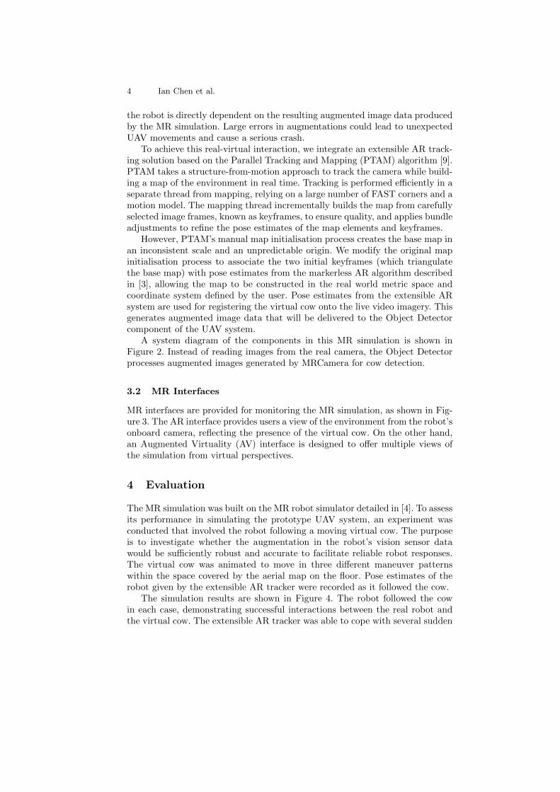
MR interfaces are provided for monitoring the MR simulation, as shown in Fig-ure 3. The AR interface provides users a view of the environment from the robot’sonboard camera, reflecting the presence of the virtual cow. On the other hand,an Augmented Virtuality (AV) interface is designed to offer multiple views ofthe simulation from virtual perspectives.
4 Evaluation
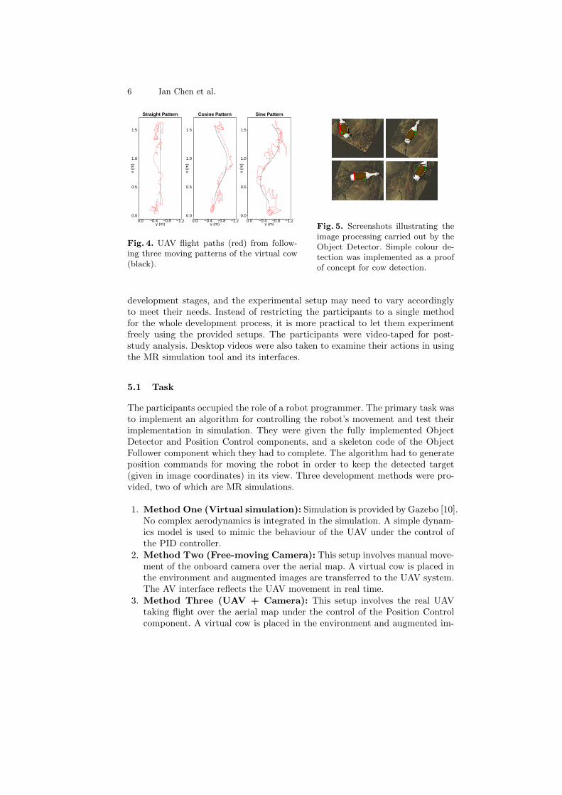
The MR simulation was built on the MR robot simulator detailed in [4]. To assessits performance in simulating the prototype UAV system, an experiment wasconducted that involved the robot following a moving virtual cow. The purposeis to investigate whether the augmentation in the robot’s vision sensor datawould be sufficiently robust and accurate to facilitate reliable robot responses.The virtual cow was animated to move in three different maneuver patternswithin the space covered by the aerial map on the floor. Pose estimates of therobot given by the extensible AR tracker were recorded as it followed the cow.
The simulation results are shown in Figure 4. The robot followed the cowin each case, demonstrating successful interactions between the real robot andthe virtual cow. The extensible AR tracker was able to cope with several sudden
Title Suppressed Due to Excessive Length 5
(a) (b) (c) (d)
Fig. 3. a) The AR interface showing a view of the scene from the robot’s perspective.b) The AV interface with free-look camera mode: in this example, the virtual camera ismoved to focus on the target cow to be monitored. c) The AV interface with tetheredcamera mode: the virtual camera follows and tracks the movement of the UAV. d) TheAV interface with fixed camera mode: similar to the tethered camera mode but with afixed virtual camera.
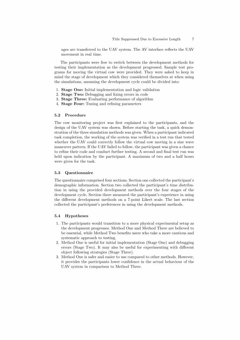
and erratic motions of the UAV and accurately augmented the virtual cow in theview of the camera. The AR tracking errors were measured to be approximately0.02m in x, 0.03m in y, and 0.06m in z. Figure 5 shows screenshots from theObject Detector window, which displays the processing being carried out on theaugmented vision data generated by the MR robot simulator. The virtual cowremained aligned with the real world scene as it was animated to move acrossthe aerial map. While no significant errors were observed in the pose estimates,it was noticed that the extensible AR tracker picked up fewer points in sceneswith large portions of grasslands due to the lack of textured content. This isan expected behaviour of the underlying PTAM algorithm used. Nevertheless,there were sufficient textured patches surrounding this grassland region in thisexperiment to maintain the tracking quality. It must be noted that future out-door experiments involving scenes with very few distinct features may cause thealgorithm to produce poor results.
Overall, the use of the MR simulation helped to provide initial insights intothe behaviour of the prototype UAV system for this cow monitoring task. TheUAV trajectories in Figure 4 (especially the sine wave pattern) revealed to therobot developers the flight instability of this prototype UAV system due to thepoor control logic of the object following algorithm, identifying the need forimprovement.
5 User Study
Our user study examines the user’s development approach and preferences inusing MR simulations for implementing robot software components. It targeted auser group of experienced robot developers and computer programmers who wererequired to write software code for controlling the UAV and test their programin simulations. The participants were provided with three development methods,including MR simulations, and it was up to the participants how they used them.We acknowledge that the task given may take the participants through different
6 Ian Chen et al.
0.0 −0.4 −0.8 −1.20.0
0.5
1.0
1.5
Straight Pattern
y (m)
x (m
)
0.0 −0.4 −0.8 −1.20.0
0.5
1.0
1.5
Cosine Pattern
y (m)
x (m
)
0.0 −0.4 −0.8 −1.20.0
0.5
1.0
1.5
Sine Pattern
y (m)
x (m
)Fig. 4. UAV flight paths (red) from follow-ing three moving patterns of the virtual cow(black).
Fig. 5. Screenshots illustrating theimage processing carried out by theObject Detector. Simple colour de-tection was implemented as a proofof concept for cow detection.
development stages, and the experimental setup may need to vary accordinglyto meet their needs. Instead of restricting the participants to a single methodfor the whole development process, it is more practical to let them experimentfreely using the provided setups. The participants were video-taped for post-study analysis. Desktop videos were also taken to examine their actions in usingthe MR simulation tool and its interfaces.
5.1 Task
The participants occupied the role of a robot programmer. The primary task wasto implement an algorithm for controlling the robot’s movement and test theirimplementation in simulation. They were given the fully implemented ObjectDetector and Position Control components, and a skeleton code of the ObjectFollower component which they had to complete. The algorithm had to generateposition commands for moving the robot in order to keep the detected target(given in image coordinates) in its view. Three development methods were pro-vided, two of which are MR simulations.
1. Method One (Virtual simulation): Simulation is provided by Gazebo [10].No complex aerodynamics is integrated in the simulation. A simple dynam-ics model is used to mimic the behaviour of the UAV under the control ofthe PID controller.
2. Method Two (Free-moving Camera): This setup involves manual move-ment of the onboard camera over the aerial map. A virtual cow is placed inthe environment and augmented images are transferred to the UAV system.The AV interface reflects the UAV movement in real time.
3. Method Three (UAV + Camera): This setup involves the real UAVtaking flight over the aerial map under the control of the Position Controlcomponent. A virtual cow is placed in the environment and augmented im-
Title Suppressed Due to Excessive Length 7
ages are transferred to the UAV system. The AV interface reflects the UAVmovement in real time.
The participants were free to switch between the development methods fortesting their implementation as the development progressed. Sample test pro-grams for moving the virtual cow were provided. They were asked to keep inmind the stage of development which they considered themselves at when usingthe simulations, assuming the development cycle could be divided into:
1. Stage One: Initial implementation and logic validation2. Stage Two: Debugging and fixing errors in code3. Stage Three: Evaluating performance of algorithm4. Stage Four: Tuning and refining parameters
5.2 Procedure
The cow monitoring project was first explained to the participants, and thedesign of the UAV system was shown. Before starting the task, a quick demon-stration of the three simulation methods was given. When a participant indicatedtask completion, the working of the system was verified in a test run that testedwhether the UAV could correctly follow the virtual cow moving in a sine wavemaneuver pattern. If the UAV failed to follow, the participant was given a chanceto refine their code and conduct further testing. A second and final test run washeld upon indication by the participant. A maximum of two and a half hourswere given for the task.
5.3 Questionnaire
The questionnaire comprised four sections. Section one collected the participant’sdemographic information. Section two collected the participant’s time distribu-tion in using the provided development methods over the four stages of thedevelopment cycle. Section three measured the participant’s experience in usingthe different development methods on a 7-point Likert scale. The last sectioncollected the participant’s preferences in using the development methods.
5.4 Hypotheses
1. The participants would transition to a more physical experimental setup asthe development progresses. Method One and Method Three are believed tobe essential, while Method Two benefits users who take a more cautious andsystematic approach to testing.
2. Method One is useful for initial implementation (Stage One) and debuggingerrors (Stage Two). It may also be useful for experimenting with differentobject following strategies (Stage Three).
3. Method One is safer and easier to use compared to other methods. However,it provides the participants lower confidence in the actual behaviour of theUAV system in comparison to Method Three.
8 Ian Chen et al.
4. Method Two is useful for helping users understand the robot’s field of view,and for validating the position commands (Stage One and Stage Two) bycomparing them against the real world experimentation area before com-mencing test flights.
5. Method Two may also be used as a safer alternative for tuning and refiningthe control parameters of the algorithm (Stage Four).
6. Method Three is heavily used in the later development stage for evaluatingperformance (Stage Three) and tuning and refining parameters (Stage Four).
7. Method Three is effective and results in fewer mistakes. The risk of testflights is also higher and the method may require a longer learning curve.
5.5 User Study Results
10 participants were recruited (4 academic researchers, 5 postgraduate stu-dents, 1 software engineer), all of whom were experienced computer programmers(mean 8.95 years of experience, SD 6.82). 7 participants had experience in robotdevelopment (mean 3.93 years of experience, SD 2.05). None had experience indeveloping aerial robot systems. The 10 participants are coded P1, P2, P3, etc.
5.6 Participant’s Development Approach
9 participants successfully completed the task within the given time. The remain-ing participant, P3, reported having struggled to understand the relationshipbetween the different coordinate systems, a respect in which the developmentmethods and the MR interfaces were unable to help the user.
More than half of the participants (6 participants) did not choose to useMethod Two. Responses were because the participants believed a) the methodwas not useful for developing control algorithms (4 comments), and b) the samebenefit of this method could be obtained using Method One and/or MethodThree (2 comments). Interestingly, different opinions were collected from 2 par-ticipants who used Method Two. P1 and P8 commented that it was necessary tosee the real environment to understand the robot’s field of view when determin-ing the starting control parameters. The non-responsiveness of the robot in thismethod was considered beneficial and they were able to debug their algorithmswhile the robot stayed in a particular position relative to the target. The findingssupported hypothesis 4 to only some extent since only a minor proportion of theparticipants used this method. A useful comment was that the benefit of us-ing Method Two could be leveraged if the simulation provided readily availablegraphical aids to help visualise the position commands in the MR interfaces.
Observations found that 9 participants began with Method One. P8 was theonly exception and decided to use Method Two to collect all the parameters andimplement the algorithm before testing it using Method One. All participantsused Method Three as the last development method. The results suggest thatthe participants slowly transitioned from virtual simulation to MR simulation(with the real UAV) as the development progressed, supporting hypothesis 1.
Title Suppressed Due to Excessive Length 9
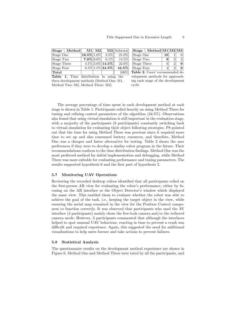
Stage \ Method M1 M2 M3 Subtotal
Stage One 16.5% 1.0% 3.5% 21.0%
Stage Two 7.8% 0.6% 6.1% 14.5%
Stage Three 4.5% 3.0% 14.5% 22.0%
Stage Four 6.5% 1.5% 34.5% 42.5%
Total 100%Table 1. Time distribution in using thethree development methods (Method One: M1,Method Two: M2, Method Three: M3)
Stage \ Method M1 M2 M3
Stage One 10 1 0
Stage Two 9 2 2
Stage Three 6 2 9
Stage Four 2 2 9Table 2. Users’ recommended de-velopment methods for approach-ing each stage of the developmentcycle.
The average percentage of time spent in each development method at eachstage is shown in Table 1. Participants relied heavily on using Method Three fortuning and refining control parameters of the algorithm (34.5%). Observationsalso found that using virtual simulation is still important in the evaluation stage,with a majority of the participants (8 participants) constantly switching backto virtual simulation for evaluating their object following strategies. P8 pointedout that the time for using Method Three was precious since it required moretime to set up and also consumed battery resources, and therefore, MethodOne was a cheaper and faster alternative for testing. Table 2 shows the userpreferences if they were to develop a similar robot program in the future. Theirrecommendations conform to the time distribution findings. Method One was themost preferred method for initial implementation and debugging, while MethodThree was more suitable for evaluating performance and tuning parameters. Theresults supported hypothesis 6 and the first part of hypothesis 2.
5.7 Monitoring UAV Operations
Reviewing the recorded desktop videos identified that all participants relied onthe first-person AR view for evaluating the robot’s performance, either by fo-cusing on the AR interface or the Object Detector’s window which displayedthe same view. This enabled them to evaluate whether the robot was able toachieve the goal of the task, i.e., keeping the target object in the view, whileensuring the aerial map remained in the view for the Position Control compo-nent to function correctly. It was observed that participants who used the AVinterface (4 participants) mainly chose the free-look camera and/or the tetheredcamera mode. However, 3 participants commented that although the interfaceshelped to spot unusual UAV behaviour, reacting in time to prevent a crash wasdifficult and required experience. Again, this suggested the need for additionalvisualisations to help users foresee and take actions to prevent failures.
5.8 Statistical Analysis
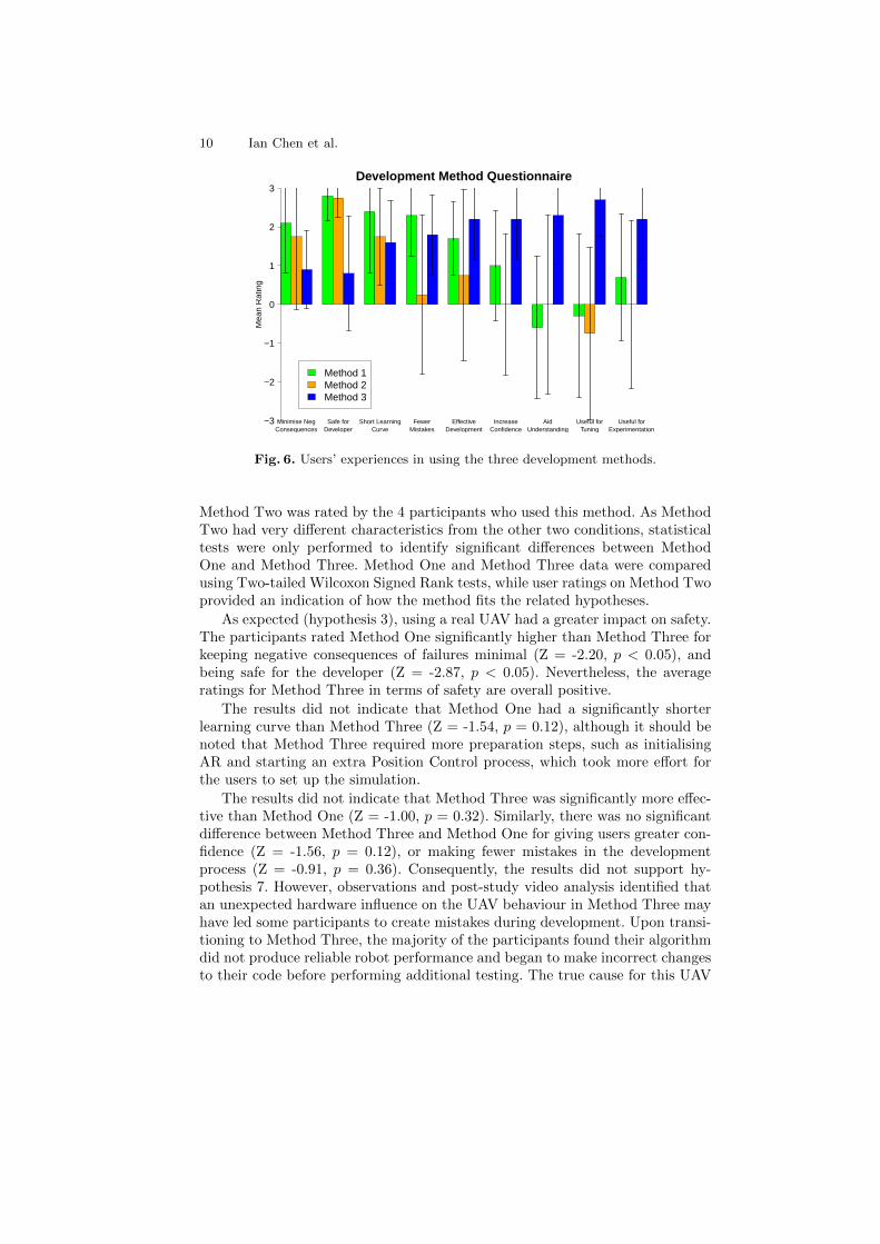
The questionnaire results on the development method experience are shown inFigure 6. Method One and Method Three were rated by all the participants, and
10 Ian Chen et al.
Minimise NegConsequences
Safe forDeveloper
Short LearningCurve
FewerMistakes
EffectiveDevelopment
IncreaseConfidence
AidUnderstanding
Useful forTuning
Useful forExperimentation
Development Method Questionnaire
Mea
n R
atin
g
−3
−2
−1
0
1
2
3
Method 1Method 2Method 3
Fig. 6. Users’ experiences in using the three development methods.
Method Two was rated by the 4 participants who used this method. As MethodTwo had very different characteristics from the other two conditions, statisticaltests were only performed to identify significant differences between MethodOne and Method Three. Method One and Method Three data were comparedusing Two-tailed Wilcoxon Signed Rank tests, while user ratings on Method Twoprovided an indication of how the method fits the related hypotheses.
As expected (hypothesis 3), using a real UAV had a greater impact on safety.The participants rated Method One significantly higher than Method Three forkeeping negative consequences of failures minimal (Z = -2.20, p < 0.05), andbeing safe for the developer (Z = -2.87, p < 0.05). Nevertheless, the averageratings for Method Three in terms of safety are overall positive.
The results did not indicate that Method One had a significantly shorterlearning curve than Method Three (Z = -1.54, p = 0.12), although it should benoted that Method Three required more preparation steps, such as initialisingAR and starting an extra Position Control process, which took more effort forthe users to set up the simulation.
The results did not indicate that Method Three was significantly more effec-tive than Method One (Z = -1.00, p = 0.32). Similarly, there was no significantdifference between Method Three and Method One for giving users greater con-fidence (Z = -1.56, p = 0.12), or making fewer mistakes in the developmentprocess (Z = -0.91, p = 0.36). Consequently, the results did not support hy-pothesis 7. However, observations and post-study video analysis identified thatan unexpected hardware influence on the UAV behaviour in Method Three mayhave led some participants to create mistakes during development. Upon transi-tioning to Method Three, the majority of the participants found their algorithmdid not produce reliable robot performance and began to make incorrect changesto their code before performing additional testing. The true cause for this UAV
Title Suppressed Due to Excessive Length 11
behaviour was due to the effect the camera cable had on the x-movement of theUAV, which was not simulated in Method One. Unfortunately, MR simulationsand the interfaces were not designed to help them isolate this problem.
The participants rated Method Three significantly higher than Method Onefor understanding the UAV flight behaviour as expected (Z = -2.57, p < 0.05),since it involved the real UAV platform in simulation. The finding could change ifa high-fidelity flight dynamics model was integrated into the virtual simulation.This needs to be investigated in the future.
Method Three was rated significantly higher than Method One for tuningcontrol parameters (Z = -2.81, p < 0.05). The findings agreed with the devel-opment method time distribution data analysis and the user recommendations,suggesting Method Three was more suitable for the later stages of the develop-ment; this further supported hypothesis 6.
Statistical analysis did not suggest that Method Three was more useful thanMethod One for experimenting with different flight maneuvers (Z = -1.80, p =0.07), though the result was approaching significance. While both average ratingswere positive, there was high variance in Method One ratings, thus the resultscould not fully support the second part of hypothesis 2. Method Two was foundto be unsuitable for tuning, which rejected hypothesis 5. P1 and P8 commentedlater in the interview that Method Two was useful for identifying (not tuning)initial control parameters, which were later tuned using Method Three.
5.9 Discussions
The results on the overall participant’s development approach may not seemsurprising but there were specific findings which were not expected. In this study,statistical analysis did not indicate that the use of MR simulation (with realUAV) was significantly more effective than virtual simulation or was it moreuseful for experimentation. The findings were however not unfavourable becauseMR simulation does not intend to replace existing simulation methods but tocomplement them during the robot development process; a hypothesis that wassupported by the results. Further research is necessary to validate the strengthsof MR simulations in a more focused, long term study that compares the use ofMR simulation alone against using only virtual simulation.
6 Conclusions
This paper contributes a case study evaluation on using MR simulations for thedevelopment of a prototype UAV system. The simulation augmented the robot’sonboard vision data with virtual inputs using a modified PTAM algorithm fortesting the cow monitoring operation. The use of the MR simulation has beenshown to help provide valuable insights into the UAV system performance thatare otherwise difficult to obtain in real world tests. User study results indicatedthat MR simulations complemented virtual simulations, providing an interme-diate experimental environment before moving onto testing in the real world. It
12 Ian Chen et al.
helped robot programmers understand UAV flight behaviours and tune controlparameters for better robot performance. Future work includes providing morevisualisation aids to improve monitoring of UAV tasks, and conducting a userstudy to identify cases where the benefits of using MR simulations are moreevident compared to traditional simulation approaches.
References
1. Ascending Technologies, http://www.asctec.de/2. Blosch, M., Weiss, S., Scaramuzza, D., Siegwart, R.: Vision based MAV navigation
in unknown and unstructured environments. In: Proceedings of the IEEE Interna-tional Conference on Robotics and Automation. pp. 21–28 (2010)
3. Chen, I.Y.H., MacDonald, B., Wunsche, B.: Markerless augmented reality forrobots in unprepared environments. In: Proceedings of the Australasian Conferenceon Robotics and Automation. Canberra, Australia (December 3–5 2008)
4. Chen, I.Y.H., MacDonald, B., Wunsche, B.: Mixed reality simulation for mobilerobots. In: Proceedings of the IEEE International Conference on Robotics andAutomation. pp. 232–237. Kobe, Japan (May 12–17 2009)
5. Chen, I.Y.H., MacDonald, B., Wunsche, B., Biggs, G., Kotoku, T.: Analysingmixed reality simulation for industrial applications: A case study in the devel-opment of a robotic screw remover system. In: Proceedings of the Second Inter-national Conference on Simulation, Modeling and Programming for AutonomousRobots. pp. 350–361. Darmstadt, Germany (November 15–18 2010)
6. Collett, T., MacDonald, B.: An augmented reality debugging system for mobilerobot software engineers. Journal of Software Engineering for Robotics 1(1), 18–32(2009)
7. Davis, B., Patron, P., Lane, D.: An augmented reality architecture for the cre-ation of hardware-in-the-loop & hybrid simulation test scenarios for unmannedunderwater vehicles. In: OCEANS. pp. 1–6 (2007)
8. Goktogan, A., Sukkarieh, S.: An Augmented Reality System for Multi-UAV Mis-sions. In: Proceedings of the Simulation Conference and Exhibition, SimTect. Cite-seer, Sydney, Australia (May 9–12 2005)
9. Klein, G., Murray, D.: Parallel tracking and mapping for small AR workspaces. In:Proceedings of the Sixth IEEE and ACM International Symposium on Mixed andAugmented Reality. pp. 225–234. Nara, Japan (November 2007)
10. Koenig, N., Howard, A.: Design and use paradigms for Gazebo, an open-sourcemulti-robot simulator. In: Proceedings of IEEE/RSJ International Conference onIntelligent Robots and Systems. vol. 3, pp. 2149–2154 (September 28–October 22004)
11. Milgram, P., Colquhoun, H.: A taxonomy of real and virtual world display inte-gration. Mixed Reality-Merging Real and Virtual Worlds pp. 5–28 (1999)
12. Nishiwaki, K., Kobayashi, K., Uchiyama, S., Yamamoto, H., Kagami, S.: Mixed re-ality environment for autonomous robot development. In: Proceedings of the IEEEInternational Conference on Robotics and Automation. pp. 2211–2212. Pasadena,CA, USA (May 2008)
13. Stilman, M., Michel, P., Chestnutt, J., Nishiwaki, K., Kagami, S., Kuffner, J.: Aug-mented reality for robot development and experimentation. Tech. Rep. CMU-RI-TR-05-55, Robotics Institute, Carnegie Mellon University, Pittsburgh, PA (Novem-ber 2005)