Embed Size (px)
Citation preview
chemengineering
Article
KLa Determination Using the Effectiveness-NTUMethod: Application to Countercurrent Absorbers inOperation Using Viscous Solvents for VOCsMass Transfer
Éric Dumont
IMT Atlantique, GEPEA, UMR CNRS 6144, F-44307 Nantes CEDEX, France; [email protected];Tel.: +33-025-185-8266
Received: 4 February 2019; Accepted: 24 May 2019; Published: 1 June 2019
Abstract: In this study, the Effectiveness-NTU method, which is usually applied to heat exchangerdesign, was adapted to gas–liquid countercurrent absorbers to determine the overall mass transfercoefficient, KLa, of the apparatus in operation. It was demonstrated that the ε-NTU method couldbe used to determine the KLa using the Henry coefficient of the solute to be transferred (HVOC),the gas flow-rate (QG), the liquid flow-rate (QL), the scrubber volume (V), and the effectiveness of theabsorber (ε). These measures are calculated from the gaseous concentrations of the solute measuredat the absorber inlet (CGin) and outlet (CGout), respectively. The ε-NTU method was validated fromliterature dedicated to the absorption of volatile organic compounds (VOCs) by heavy solvents.Therefore, this method could be a simple, robust, and reliable tool for the KLa determination ofgas–liquid contactors in operation, despite the type of liquid used, i.e., water or viscous solvents.
Keywords: absorption; mass transfer; heat exchanger; scrubber; effectiveness-NTU method
1. Introduction
The removal of volatile organic compounds (VOCs) from the air can be achieved using gas–liquidreactors. However, some VOCs are poorly soluble in water leading to mass transfer limitations.In response to the low solubility of hydrophobic pollutants, water can be replaced by heavy viscousorganic solvents (silicone oils, alkanes, phthalates, [1]) to improve the mass transfer [2]. Basically, theabsorption step is crucial, since VOCs have to be solubilized for further treatments. Usually, the masstransfer between the gas phase and the liquid phase (water) is performed in countercurrent gas–liquidpacked absorbers, where the design procedure is clearly described in the extant literature [3–5]. Basically,the design of absorbers implies the use of hydrodynamic studies to determine the gas–liquid two-phaseflows in the column and mass transfer studies, so as to calculate the absorption efficiency according tothe height of the column. The overall volumetric mass transfer coefficient KLa, which depends on thelocal volumetric mass transfer coefficients (kLa, kGa) and on the Henry coefficient, is a key parameterin the calculation of the absorption efficiency, and subsequently in the reactor design. However,for viscous solvents, the physico–chemical properties of the couple COV/solvent (mainly the Henrycoefficient and the liquid diffusivity) are not sufficiently known to enable an accurate KLa predictionfrom empirical correlations. Additionally, in the case of VOCs absorption by mixtures of two immiscibleliquids (i.e., multiphasic gas–liquid–liquid systems), the KLa cannot be predicted. Several techniquesfor experimental KLa determination exist; however, considerable problems concerning the accuracyof the measurements in relation to the high viscosity of the solvents have been encountered [6,7].Moreover, these techniques cannot be applied to multiphasic gas–liquid–liquid systems. Therefore,the aim of this study was to develop a generally applicable method for experimentally determining
ChemEngineering 2019, 3, 57; doi:10.3390/chemengineering3020057 www.mdpi.com/journal/chemengineering
ChemEngineering 2019, 3, 57 2 of 15
the overall volumetric mass transfer coefficient in the liquid phase, KLa, regardless of the solute tobe transferred, the solvent and the packing material used, the operating conditions applied, andthe hydrodynamic conditions encountered in the gas–liquid absorber. This method, based on the“effectiveness-NTU” method used for the design of heat exchangers [8], could then be considered as acomplementary tool for KLa determination to the empirical correlations usually applied.
2. Gas–Liquid Absorber Analysis
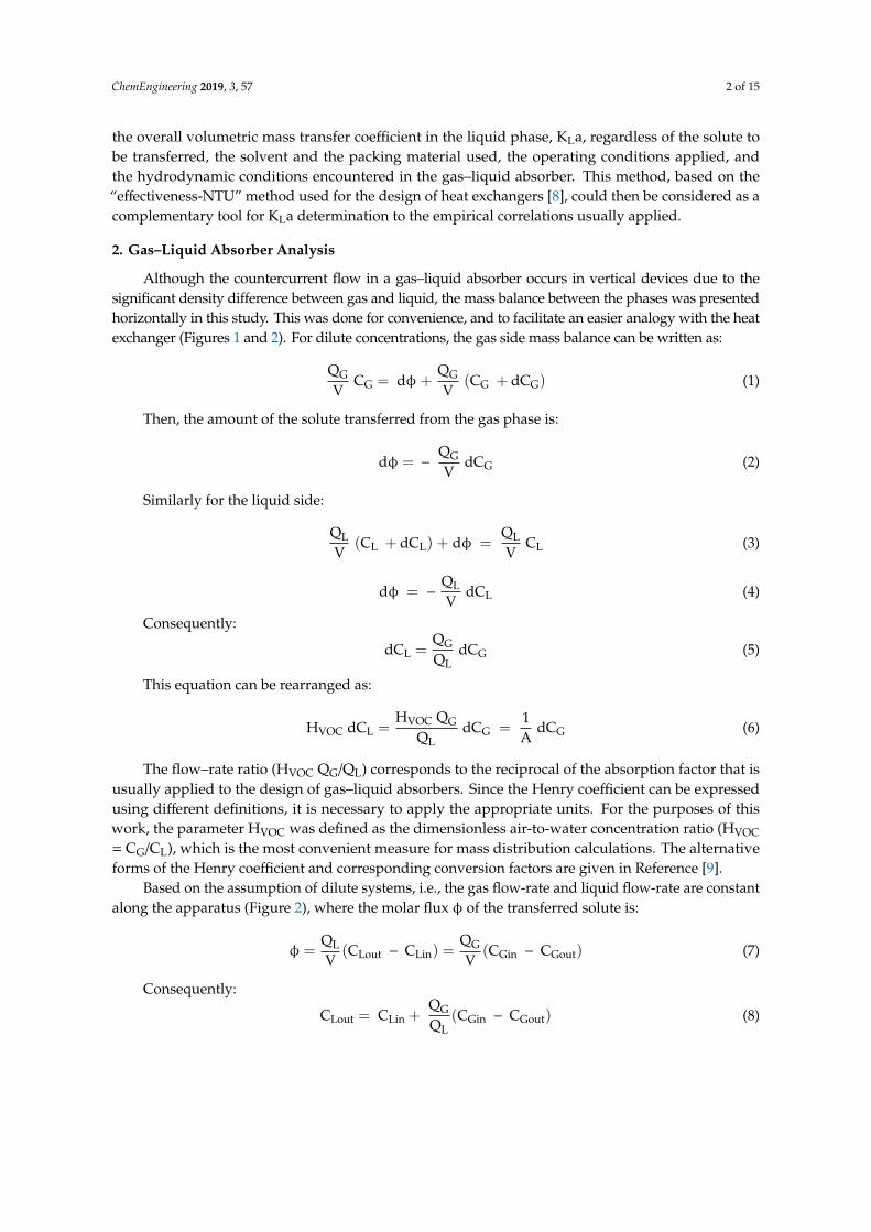
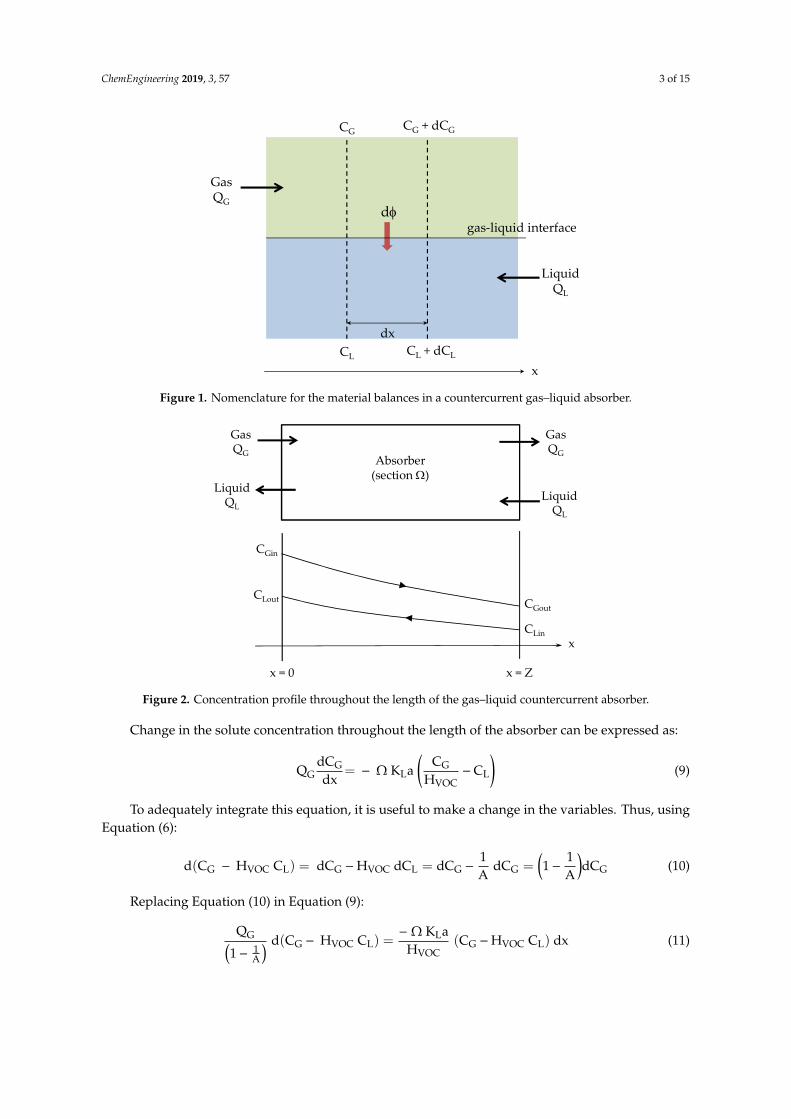
Although the countercurrent flow in a gas–liquid absorber occurs in vertical devices due to thesignificant density difference between gas and liquid, the mass balance between the phases was presentedhorizontally in this study. This was done for convenience, and to facilitate an easier analogy with the heatexchanger (Figures 1 and 2). For dilute concentrations, the gas side mass balance can be written as:
QG
VCG = dφ +
QG
V(CG + dCG) (1)
Then, the amount of the solute transferred from the gas phase is:
dφ = −QG
VdCG (2)
Similarly for the liquid side:
QL
V(CL + dCL) + dφ =
QL
VCL (3)
dφ = −QL
VdCL (4)
Consequently:
dCL =QG
QLdCG (5)
This equation can be rearranged as:
HVOC dCL =HVOC QG
QLdCG =
1A
dCG (6)
The flow–rate ratio (HVOC QG/QL) corresponds to the reciprocal of the absorption factor that isusually applied to the design of gas–liquid absorbers. Since the Henry coefficient can be expressedusing different definitions, it is necessary to apply the appropriate units. For the purposes of thiswork, the parameter HVOC was defined as the dimensionless air-to-water concentration ratio (HVOC
= CG/CL), which is the most convenient measure for mass distribution calculations. The alternativeforms of the Henry coefficient and corresponding conversion factors are given in Reference [9].
Based on the assumption of dilute systems, i.e., the gas flow-rate and liquid flow-rate are constantalong the apparatus (Figure 2), where the molar flux φ of the transferred solute is:
φ =QL
V(CLout − CLin) =
QG
V(CGin − CGout) (7)
Consequently:
CLout = CLin +QG
QL(CGin − CGout) (8)
ChemEngineering 2019, 3, 57 3 of 15ChemEngineering 2019, 3, x FOR PEER REVIEW 3 of 16
Figure 1. Nomenclature for the material balances in a countercurrent gas–liquid absorber.
Figure 2. Concentration profile throughout the length of the gas–liquid countercurrent absorber.
Based on the assumption of dilute systems, i.e., the gas flow-rate and liquid flow-rate are constant along the apparatus (Figure 2), where the molar flux of the transferred solute is:
ϕ = Q
V(CLout − C ) =
Q
V(CGin − C ) (7)
Consequently:
CLout = CLin + Q
Q(CGin − C ) (8)
Change in the solute concentration throughout the length of the absorber can be expressed as:
QdCG
dx= − Ω K a
C
H− C (9)
To adequately integrate this equation, it is useful to make a change in the variables. Thus, using Equation (6):
d(CG − H C ) = dCG − H dC = dCG −1
A dC = 1 −
1
AdC (10)
Replacing Equation (10) in Equation (9):
GasQG
LiquidQL
gas-liquid interface
CL + dCL
d
x
dxCL
CG CG + dCG
GasQG
LiquidQL
xCLin
CGin
GasQG
LiquidQL
x = 0 x = Z
CGoutCLout
Absorber (section W)
Figure 1. Nomenclature for the material balances in a countercurrent gas–liquid absorber.
ChemEngineering 2019, 3, x FOR PEER REVIEW 3 of 16
Figure 1. Nomenclature for the material balances in a countercurrent gas–liquid absorber.
Figure 2. Concentration profile throughout the length of the gas–liquid countercurrent absorber.
Based on the assumption of dilute systems, i.e., the gas flow-rate and liquid flow-rate are constant along the apparatus (Figure 2), where the molar flux of the transferred solute is:
ϕ = Q
V(CLout − C ) =
Q
V(CGin − C ) (7)
Consequently:
CLout = CLin + Q
Q(CGin − C ) (8)
Change in the solute concentration throughout the length of the absorber can be expressed as:
QdCG
dx= − Ω K a
C
H− C (9)
To adequately integrate this equation, it is useful to make a change in the variables. Thus, using Equation (6):
d(CG − H C ) = dCG − H dC = dCG −1
A dC = 1 −
1
AdC (10)
Replacing Equation (10) in Equation (9):
GasQG
LiquidQL
gas-liquid interface
CL + dCL
d
x
dxCL
CG CG + dCG
GasQG
LiquidQL
xCLin
CGin
GasQG
LiquidQL
x = 0 x = Z
CGoutCLout
Absorber (section W)
Figure 2. Concentration profile throughout the length of the gas–liquid countercurrent absorber.
Change in the solute concentration throughout the length of the absorber can be expressed as:
QGdCG
dx= − Ω KLa
(CG
HVOC−CL
)(9)
To adequately integrate this equation, it is useful to make a change in the variables. Thus, usingEquation (6):
d(CG − HVOC CL) = dCG −HVOC dCL = dCG −1A
dCG =(1−
1A
)dCG (10)
Replacing Equation (10) in Equation (9):
QG(1− 1
A
) d(CG − HVOC CL) =− Ω KLa
HVOC(CG −HVOC CL) dx (11)
ChemEngineering 2019, 3, 57 4 of 15
Considering that concentrations of the values CG and CL are given at positions x = 0 and x = Z inFigure 2, the solution to this equation, integrated between x = 0 and x = Z, is:
ln[(CGout − HVOC CLin)
(CGin − HVOC CLout)
]=− Ω Z KLaHVOC QG
(1−
1A
)(12)
As (ΩZ) is the volume of the apparatus, Equation (12) can be rearranged under the followingform:
(CGout − HVOC CLin)
(CGin − HVOC CLout)= exp
(− NTU
(1−
1A
))(13)
With:NTU =
KLaHVOC
VQG
(14)
In Equation (14), the dimensionless number of transfer units (NTU) corresponds to the ratio of thegas residence time in the device (V/QG) to the time needed for the mass transfer of the solute fromthe gas phase to the liquid phase (HVOC/KLa). This NTU parameter can be directly compared to theNTU parameter used in the heat exchanger design (Table 1). Moreover, the reciprocal of the absorptionfactor (HVOC QG/QL) is also directly comparable to the relative magnitudes of the hot and cold fluidheat capacity rates that are used in the heat exchanger design. Consequently, the analogy with the heatexchanger design implies the definition of the maximum possible mass transfer rate φmax betweenthe gas phase and the liquid phase. Assuming a countercurrent absorber of infinite length, the soluteconcentrations in the gas phase and in the liquid phase are at an equilibrium. Therefore, CGout tends to(HVOC CLin) at x→∞ and:
φmax =QG
V(CGin − HVOC CLin) (15)
The effectiveness of the absorber, ε, can be defined as the ratio of the actual mass transfer rate φ(Equation (7)) to the maximum possible mass transfer rate φmax:
ε =φ
φmax=
(CGin − CGout)
(CGin − HVOC CLin)(16)
According to Equation (16), the solute gas concentration at the outlet of the absorber CGout wouldtend toward zero only for a countercurrent absorber of infinite length using a solute-free liquid, i.e.,CLin = 0. It should be noted that the inlet liquid concentration is usually equal to zero, and consequentlyε = (CGin−CGout)/CGin, which corresponds to the equation that is generally applied to determine theabsorber efficiency. Combining Equations (8), (13), and (16), the effectiveness of the absorber can beexpressed using the following form (calculation details are given in Appendix A):
ε =1− exp
(− NTU
(A−1
A
))1− 1
A exp(− NTU
(A−1
A
)) (17)
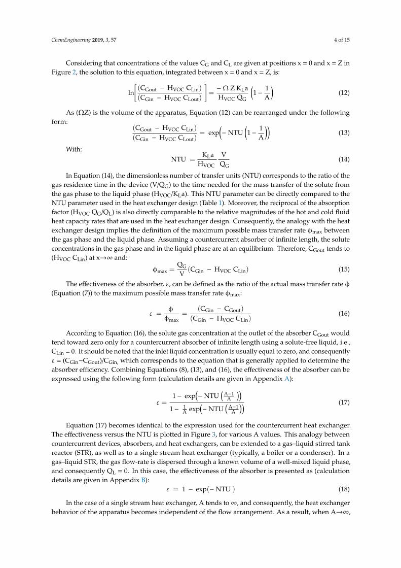
Equation (17) becomes identical to the expression used for the countercurrent heat exchanger.The effectiveness versus the NTU is plotted in Figure 3, for various A values. This analogy betweencountercurrent devices, absorbers, and heat exchangers, can be extended to a gas–liquid stirred tankreactor (STR), as well as to a single stream heat exchanger (typically, a boiler or a condenser). In agas–liquid STR, the gas flow-rate is dispersed through a known volume of a well-mixed liquid phase,and consequently QL = 0. In this case, the effectiveness of the absorber is presented as (calculationdetails are given in Appendix B):
ε = 1 − exp(− NTU ) (18)
In the case of a single stream heat exchanger, A tends to∞, and consequently, the heat exchangerbehavior of the apparatus becomes independent of the flow arrangement. As a result, when A→∞,
ChemEngineering 2019, 3, 57 5 of 15
Equation (17) is reduced to Equation (18). The analogies between the heat and mass transfer given inthe current paper are summarized in Table 1.
ChemEngineering 2019, 3, x FOR PEER REVIEW 5 of 16
ε = 1 − exp(− NTU ) (18)
In the case of a single stream heat exchanger, A tends to ∞, and consequently, the heat exchanger behavior of the apparatus becomes independent of the flow arrangement. As a result, when A→∞, Equation (17) is reduced to Equation (18). The analogies between the heat and mass transfer given in the current paper are summarized in Table 1.
Figure 3. Effectiveness (ε) of a countercurrent gas–liquid absorber versus the number transfer units (NTU).
0.0
0.1
0.2
0.3
0.4
0.5
0.6
0.7
0.8
0.9
1.0
0 1 2 3 4 5 6
e
NTU
A=100
A=4
A=2
A=1.33
A=1
Biard et al. [1] (Pall rings)
Bourgois et al. [6] (cables-bundle)
Guillerm et al. [10] (Raschig rings)
Guillerm et al. [10] (IMTP)
Guillerm et al. [10] (Flexipac)
A = 4A = 2A = 1.33A → 1
A → ∞
Figure 3. Effectiveness (ε) of a countercurrent gas–liquid absorber versus the number transfer units(NTU).
Table 1. The effectiveness-NTU method for the countercurrent devices. Analogy between the gas–liquidmass absorber and the heat exchanger (see nomenclature for details).
Mass Absorber Heat Exchanger
Physical parameter Concentration C (mol m−3) Temperature T (K)
Transfer coefficient KL (m s−1) U (W m−2 K−1)
Transfer surface area a V (m2) A (m2)
Transfer rate
φ =QLV (CLout − CLin)
φ =QGV (CGin − CGout)
φ = KLa ∆CML(mol m−3 s−1)
φ = Mc Cpc (Tcout − Tcin)φ = Mh Cph (Thin − Thout)φ = U A ∆TML(W)
Maximum possible transfer rate φmax =QGV (CGin −HVOCCLin)
(mol m−3 s−1)φmax = Cmin (Thin − Tcin)(W)
Effectiveness(dimensionless)ε = φ
φmax
ε =(CGin − CGout)
(CGin − HVOC CLin)
ε =1 − exp(− NTU (1− 1
A ))1 − 1
A exp(− NTU (1− 1A ))
ε =max((Tcout − Tcin),(Thin− Thout))
(Thin−Tcin)
ε =1 − exp(− NTU (1−R))
1− R exp(− NTU (1−R))
1A =
HVOC QGQL
R = CminCmax
NTU (dimensionless) KLaHVOC
VQG
U ACmin

ChemEngineering 2019, 3, 57 6 of 15
3. Validation of the ε-NTU Method from the Data Reported in the Literature
The aim of this section is to demonstrate that the use of the ε-NTU method permits the calculationof the overall mass transfer coefficient, KLa, of an operating absorber when parameters QL, QG, V,HVOC, and ε are known. The validation is based on data from three studies [1,6,10], as detailed inTable 2. As observed, the experimental data are diversified in terms of solvent used, solutes to betransferred (i.e., various HVOC values), and operating conditions. From the absorption efficiencyvalues reported in these studies, the NTU and KLa values were calculated using Equations (19) and(14), respectively.
NTU =A
1−Aln
(ε− 1ε/A− 1
)(19)
All experimental results are reported in Figure 3.
Table 2. Literature data used for the KLa determination using the ε-NTU method.
Solvent Solute HVOC Operating Conditions Ref
Water 1 mPa s
TolueneDichloromethane
PropanolAcetone
2.09 × 10⁻¹
9.03 × 10⁻²
1.27 × 10⁻⁴
9.36 × 10⁻⁴
V = 2.36 m3
Packed column (Pall rings)QL = 3.06 × 10⁻³ m3/sQG: 1.20 m3/s(gas EBRT: 2 s)20 C
Study n1[1]
DEHA(bis(di-2-ethylhexyl)adipate)
12.5 mPa s
TolueneDichloromethane
PropanolAcetone
3.12 × 10⁻⁴
1.94 × 10⁻³
2.70 × 10⁻³
5.21 × 10⁻³
Silicone oil 50 mPa s
TolueneDichloromethane
PropanolAcetone
5.58 × 10⁻⁴
9.04 × 10⁻³
8.79 × 10⁻³
2.17 × 10⁻²
DEHP (di-2-ethylhexylphthalate) 76 mPa s
HexaneTolueneOctane
Methylcyclohexane
4.74 × 10⁻³
3.19 × 10⁻⁴
4.40 × 10⁻⁴
9.79 × 10⁻⁴
V = 1.46 × 10⁻² m3
Cables-bundle contactorQL = 1.00 × 10⁻⁵; 1.25 × 10⁻⁵;1.50 × 10⁻⁵ m3/sQG: 1.39 × 10⁻² m3/s(gas EBRT: 1 s)20 C
Study n2[6]
Silicone oil 50 mPa s Toluene 1.17 × 10⁻³
V = 1.13 × 10⁻² m3
Packed column (Raschig rings)QL = 1.53 × 10⁻⁵–4.58 × 10⁻⁵ m3/sQG: 7.15 × 10⁻³ m3/s(gas EBRT: 1.6 s)25 C
Study n3[10]
Silicone oil 50 mPa s Toluene 1.17 × 10⁻³
V = 1.13 10−2 m3
Packed column (IMTP®)QL = 6.62 × 10⁻⁶–1.16 × 10⁻⁴ m3/sQG: 1.10 × 10⁻² m3/s(gas EBRT: 1 s)25 C
Study n3[10]
Silicone oil 50 mPa sSilicone oil 5 mPa s
TolueneToluene
1.17 × 10⁻³
1.09 × 10⁻³
V = 1.13 × 10⁻² m3
Packed column (Flexipac®)QL = 1.36 × 10⁻⁵–9.28 × 10⁻⁵ m3/sQG: 1.10 × 10⁻² m3/s(gas EBRT: 1 s)25 C
Study n3[10]
3.1. Data from Study n1
Biard et al. [1] proposed a simulation of the absorption of hydrophilic and hydrophobic compounds(toluene, dichloromethane, propanol, and acetone) in pure water and pure organic solvents (siliconeoil and DEHA, i.e., bis(di-2-ethylhexyl)adipate). A countercurrent column packed with metal Pallrings was used for this purpose. The authors calculated the KLa values according to the Billet–Schultes
ChemEngineering 2019, 3, 57 7 of 15
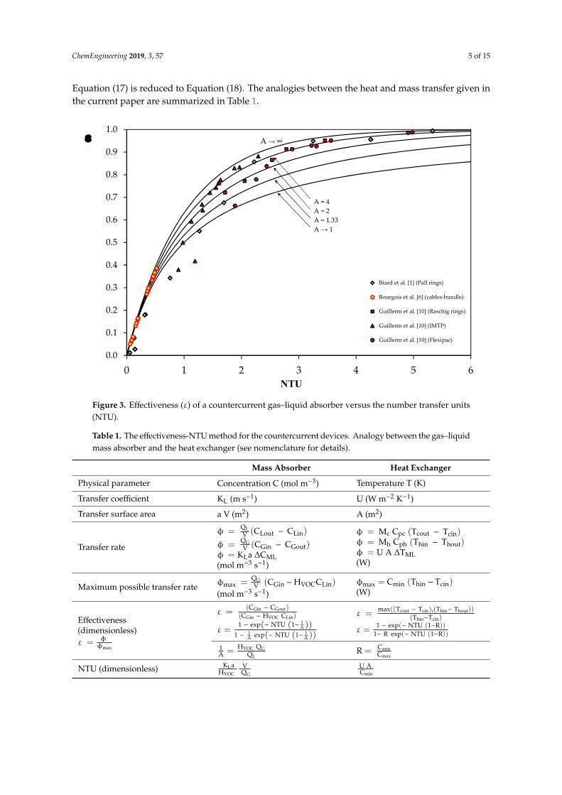
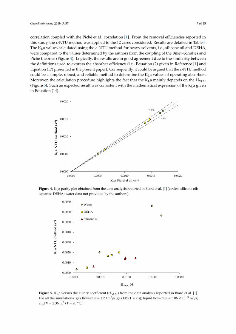
correlation coupled with the Piché et al. correlation [1]. From the removal efficiencies reported inthis study, the ε-NTU method was applied to the 12 cases considered. Results are detailed in Table 3.The KLa values calculated using the ε-NTU method for heavy solvents, i.e., silicone oil and DEHA,were compared to the values determined by the authors from the coupling of the Billet–Schultes andPiché theories (Figure 4). Logically, the results are in good agreement due to the similarity betweenthe definitions used to express the absorber efficiency (i.e., Equation (2) given in Reference [1] andEquation (17) presented in the present paper). Consequently, it could be argued that the ε-NTU methodcould be a simple, robust, and reliable method to determine the KLa values of operating absorbers.Moreover, the calculation procedure highlights the fact that the KLa mainly depends on the HVOC
(Figure 5). Such an expected result was consistent with the mathematical expression of the KLa givenin Equation (14).
ChemEngineering 2019, 3, x FOR PEER REVIEW 8 of 16
that the ε-NTU method could be a simple, robust, and reliable method to determine the KLa values of operating absorbers. Moreover, the calculation procedure highlights the fact that the KLa mainly depends on the HVOC (Figure 5). Such an expected result was consistent with the mathematical expression of the KLa given in Equation (14).
Figure 4. KLa parity plot obtained from the data analysis reported in Biard et al. [1] (circles: silicone oil; squares: DEHA; water data not provided by the authors).
Figure 5. KLa versus the Henry coefficient (HVOC) from the data analysis reported in Biard et al. [1]. For all the simulations: gas flow-rate = 1.20 m3/s (gas EBRT = 2 s); liquid flow-rate = 3.06 × 10⁻³ m3/s; and V = 2.36 m3 (T = 20 °C).
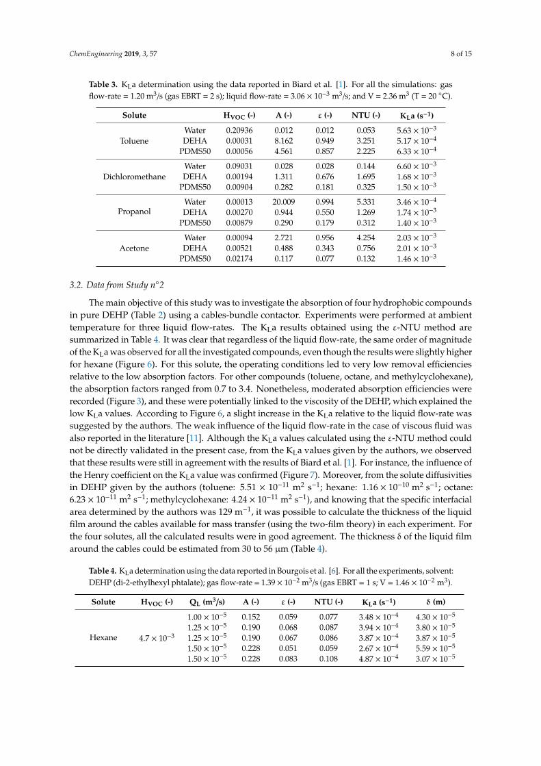
Table 3. KLa determination using the data reported in Biard et al. [1]. For all the simulations: gas flow-rate = 1.20 m3/s (gas EBRT = 2 s); liquid flow-rate = 3.06 × 10⁻³ m3/s; and V = 2.36 m3 (T = 20 °C).
0.0000
0.0005
0.0010
0.0015
0.0020
0.0000 0.0005 0.0010 0.0015 0.0020
KLa
NTU
met
hod
(s-1
)
KLa Biard et al. (s-1)
+ 5%
- 5%
0.0000
0.0010
0.0020
0.0030
0.0040
0.0050
0.0060
0.0070
0.0001 0.0010 0.0100 0.1000 1.0000
KLa
NTU
met
hod
(s-1
)
HVOC (-)
Water
DEHA
Silicone oil
Figure 4. KLa parity plot obtained from the data analysis reported in Biard et al. [1] (circles: silicone oil;squares: DEHA; water data not provided by the authors).
ChemEngineering 2019, 3, x FOR PEER REVIEW 8 of 16
that the ε-NTU method could be a simple, robust, and reliable method to determine the KLa values of operating absorbers. Moreover, the calculation procedure highlights the fact that the KLa mainly depends on the HVOC (Figure 5). Such an expected result was consistent with the mathematical expression of the KLa given in Equation (14).
Figure 4. KLa parity plot obtained from the data analysis reported in Biard et al. [1] (circles: silicone oil; squares: DEHA; water data not provided by the authors).
Figure 5. KLa versus the Henry coefficient (HVOC) from the data analysis reported in Biard et al. [1]. For all the simulations: gas flow-rate = 1.20 m3/s (gas EBRT = 2 s); liquid flow-rate = 3.06 × 10⁻³ m3/s; and V = 2.36 m3 (T = 20 °C).
Table 3. KLa determination using the data reported in Biard et al. [1]. For all the simulations: gas flow-rate = 1.20 m3/s (gas EBRT = 2 s); liquid flow-rate = 3.06 × 10⁻³ m3/s; and V = 2.36 m3 (T = 20 °C).
0.0000
0.0005
0.0010
0.0015
0.0020
0.0000 0.0005 0.0010 0.0015 0.0020
KLa
NTU
met
hod
(s-1
)
KLa Biard et al. (s-1)
+ 5%
- 5%
0.0000
0.0010
0.0020
0.0030
0.0040
0.0050
0.0060
0.0070
0.0001 0.0010 0.0100 0.1000 1.0000
KLa
NTU
met
hod
(s-1
)
HVOC (-)
Water
DEHA
Silicone oil
Figure 5. KLa versus the Henry coefficient (HVOC) from the data analysis reported in Biard et al. [1].For all the simulations: gas flow-rate = 1.20 m3/s (gas EBRT = 2 s); liquid flow-rate = 3.06 × 10⁻³ m3/s;and V = 2.36 m3 (T = 20 C).
ChemEngineering 2019, 3, 57 8 of 15
Table 3. KLa determination using the data reported in Biard et al. [1]. For all the simulations: gasflow-rate = 1.20 m3/s (gas EBRT = 2 s); liquid flow-rate = 3.06 × 10⁻³ m3/s; and V = 2.36 m3 (T = 20 C).
Solute HVOC (-) A (-) ε (-) NTU (-) KLa (s−1)
TolueneWater 0.20936 0.012 0.012 0.053 5.63 × 10⁻³
DEHA 0.00031 8.162 0.949 3.251 5.17 × 10⁻⁴
PDMS50 0.00056 4.561 0.857 2.225 6.33 × 10⁻⁴
DichloromethaneWater 0.09031 0.028 0.028 0.144 6.60 × 10⁻³
DEHA 0.00194 1.311 0.676 1.695 1.68 × 10⁻³
PDMS50 0.00904 0.282 0.181 0.325 1.50 × 10⁻³
PropanolWater 0.00013 20.009 0.994 5.331 3.46 × 10⁻⁴
DEHA 0.00270 0.944 0.550 1.269 1.74 × 10⁻³
PDMS50 0.00879 0.290 0.179 0.312 1.40 × 10⁻³
AcetoneWater 0.00094 2.721 0.956 4.254 2.03 × 10⁻³
DEHA 0.00521 0.488 0.343 0.756 2.01 × 10⁻³
PDMS50 0.02174 0.117 0.077 0.132 1.46 × 10⁻³
3.2. Data from Study n2
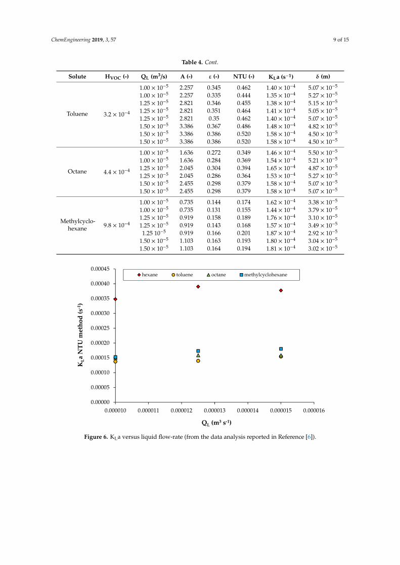
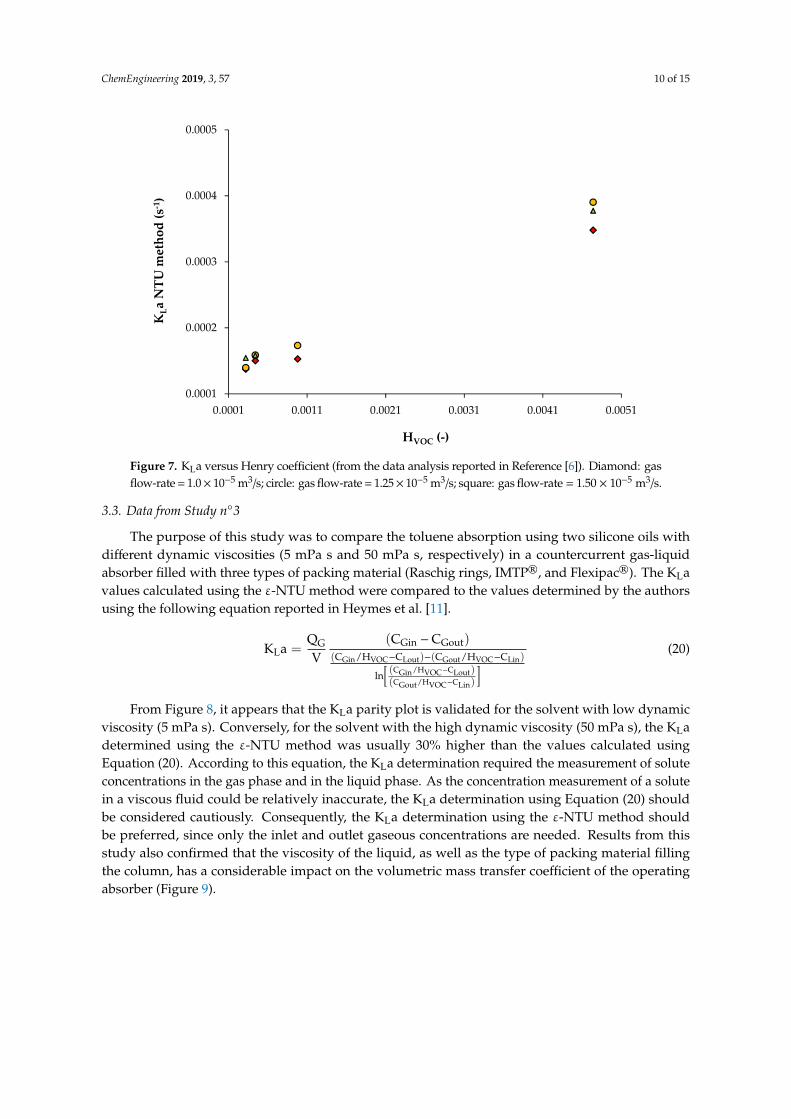
The main objective of this study was to investigate the absorption of four hydrophobic compoundsin pure DEHP (Table 2) using a cables-bundle contactor. Experiments were performed at ambienttemperature for three liquid flow-rates. The KLa results obtained using the ε-NTU method aresummarized in Table 4. It was clear that regardless of the liquid flow-rate, the same order of magnitudeof the KLa was observed for all the investigated compounds, even though the results were slightly higherfor hexane (Figure 6). For this solute, the operating conditions led to very low removal efficienciesrelative to the low absorption factors. For other compounds (toluene, octane, and methylcyclohexane),the absorption factors ranged from 0.7 to 3.4. Nonetheless, moderated absorption efficiencies wererecorded (Figure 3), and these were potentially linked to the viscosity of the DEHP, which explained thelow KLa values. According to Figure 6, a slight increase in the KLa relative to the liquid flow-rate wassuggested by the authors. The weak influence of the liquid flow-rate in the case of viscous fluid wasalso reported in the literature [11]. Although the KLa values calculated using the ε-NTU method couldnot be directly validated in the present case, from the KLa values given by the authors, we observedthat these results were still in agreement with the results of Biard et al. [1]. For instance, the influence ofthe Henry coefficient on the KLa value was confirmed (Figure 7). Moreover, from the solute diffusivitiesin DEHP given by the authors (toluene: 5.51 × 10⁻¹¹ m2 s−1; hexane: 1.16 × 10⁻¹⁰ m2 s−1; octane:6.23 × 10⁻¹¹ m2 s−1; methylcyclohexane: 4.24 × 10⁻¹¹ m2 s−1), and knowing that the specific interfacialarea determined by the authors was 129 m−1, it was possible to calculate the thickness of the liquidfilm around the cables available for mass transfer (using the two-film theory) in each experiment. Forthe four solutes, all the calculated results were in good agreement. The thickness δ of the liquid filmaround the cables could be estimated from 30 to 56 µm (Table 4).
Table 4. KLa determination using the data reported in Bourgois et al. [6]. For all the experiments, solvent:DEHP (di-2-ethylhexyl phtalate); gas flow-rate = 1.39 × 10⁻² m3/s (gas EBRT = 1 s; V = 1.46 × 10⁻² m3).
Solute HVOC (-) QL (m3/s) A (-) ε (-) NTU (-) KLa (s−1) δ (m)
Hexane 4.7 × 10⁻³
1.00 × 10⁻⁵ 0.152 0.059 0.077 3.48 × 10⁻⁴ 4.30 × 10⁻⁵
1.25 × 10⁻⁵ 0.190 0.068 0.087 3.94 × 10⁻⁴ 3.80 × 10⁻⁵
1.25 × 10⁻⁵ 0.190 0.067 0.086 3.87 × 10⁻⁴ 3.87 × 10⁻⁵
1.50 × 10⁻⁵ 0.228 0.051 0.059 2.67 × 10⁻⁴ 5.59 × 10⁻⁵
1.50 × 10⁻⁵ 0.228 0.083 0.108 4.87 × 10⁻⁴ 3.07 × 10⁻⁵
ChemEngineering 2019, 3, 57 9 of 15
Table 4. Cont.
Solute HVOC (-) QL (m3/s) A (-) ε (-) NTU (-) KLa (s−1) δ (m)
Toluene 3.2 × 10⁻⁴
1.00 × 10⁻⁵ 2.257 0.345 0.462 1.40 × 10⁻⁴ 5.07 × 10⁻⁵
1.00 × 10⁻⁵ 2.257 0.335 0.444 1.35 × 10⁻⁴ 5.27 × 10⁻⁵
1.25 × 10⁻⁵ 2.821 0.346 0.455 1.38 × 10⁻⁴ 5.15 × 10⁻⁵
1.25 × 10⁻⁵ 2.821 0.351 0.464 1.41 × 10⁻⁴ 5.05 × 10⁻⁵
1.25 × 10⁻⁵ 2.821 0.35 0.462 1.40 × 10⁻⁴ 5.07 × 10⁻⁵
1.50 × 10⁻⁵ 3.386 0.367 0.486 1.48 × 10⁻⁴ 4.82 × 10⁻⁵
1.50 × 10⁻⁵ 3.386 0.386 0.520 1.58 × 10⁻⁴ 4.50 × 10⁻⁵
1.50 × 10⁻⁵ 3.386 0.386 0.520 1.58 × 10⁻⁴ 4.50 × 10⁻⁵
Octane 4.4 × 10⁻⁴
1.00 × 10⁻⁵ 1.636 0.272 0.349 1.46 × 10⁻⁴ 5.50 × 10⁻⁵
1.00 × 10⁻⁵ 1.636 0.284 0.369 1.54 × 10⁻⁴ 5.21 × 10⁻⁵
1.25 × 10⁻⁵ 2.045 0.304 0.394 1.65 × 10⁻⁴ 4.87 × 10⁻⁵
1.25 × 10⁻⁵ 2.045 0.286 0.364 1.53 × 10⁻⁴ 5.27 × 10⁻⁵
1.50 × 10⁻⁵ 2.455 0.298 0.379 1.58 × 10⁻⁴ 5.07 × 10⁻⁵
1.50 × 10⁻⁵ 2.455 0.298 0.379 1.58 × 10⁻⁴ 5.07 × 10⁻⁵
Methylcyclo-hexane 9.8 × 10⁻⁴
1.00 × 10⁻⁵ 0.735 0.144 0.174 1.62 × 10⁻⁴ 3.38 × 10⁻⁵
1.00 × 10⁻⁵ 0.735 0.131 0.155 1.44 × 10⁻⁴ 3.79 × 10⁻⁵
1.25 × 10⁻⁵ 0.919 0.158 0.189 1.76 × 10⁻⁴ 3.10 × 10⁻⁵
1.25 × 10⁻⁵ 0.919 0.143 0.168 1.57 × 10⁻⁴ 3.49 × 10⁻⁵
1.25 10−5 0.919 0.166 0.201 1.87 × 10⁻⁴ 2.92 × 10⁻⁵
1.50 × 10⁻⁵ 1.103 0.163 0.193 1.80 × 10⁻⁴ 3.04 × 10⁻⁵
1.50 × 10⁻⁵ 1.103 0.164 0.194 1.81 × 10⁻⁴ 3.02 × 10⁻⁵ChemEngineering 2019, 3, x FOR PEER REVIEW 10 of 16
Figure 6. KLa versus liquid flow-rate (from the data analysis reported in Reference [6]).
Figure 7. KLa versus Henry coefficient (from the data analysis reported in Reference [6]). Diamond: gas flow-rate = 1.0 × 10⁻⁵ m3/s; circle: gas flow-rate = 1.25 × 10⁻⁵ m3/s; square: gas flow-rate = 1.50 × 10⁻⁵ m3/s.
Table 4. KLa determination using the data reported in Bourgois et al. [6]. For all the experiments, solvent: DEHP (di-2-ethylhexyl phtalate); gas flow-rate = 1.39 × 10⁻² m3/s (gas EBRT = 1 s; V = 1.46 × 10⁻² m3).
Solute HVOC (-) QL (m3/s) A (-) ε (-) NTU (-) KLa (s−1) δ (m)
Hexane 4.7 × 10⁻³ 1.00 × 10⁻⁵ 0.152 0.059 0.077 3.48 × 10⁻⁴ 4.30 × 10⁻⁵ 1.25 × 10⁻⁵ 0.190 0.068 0.087 3.94 × 10⁻⁴ 3.80 × 10⁻⁵ 1.25 × 10⁻⁵ 0.190 0.067 0.086 3.87 × 10⁻⁴ 3.87 × 10⁻⁵
0.00000
0.00005
0.00010
0.00015
0.00020
0.00025
0.00030
0.00035
0.00040
0.00045
0.000010 0.000011 0.000012 0.000013 0.000014 0.000015 0.000016
KLa
NTU
met
hod
(s-1
)
QL (m3 s-1)
hexane toluene octane methylcyclohexane
0.0001
0.0002
0.0003
0.0004
0.0005
0.0001 0.0011 0.0021 0.0031 0.0041 0.0051
KLa
NTU
met
hod
(s-1
)
HVOC (-)
Figure 6. KLa versus liquid flow-rate (from the data analysis reported in Reference [6]).
ChemEngineering 2019, 3, 57 10 of 15
ChemEngineering 2019, 3, x FOR PEER REVIEW 10 of 16
Figure 6. KLa versus liquid flow-rate (from the data analysis reported in Reference [6]).
Figure 7. KLa versus Henry coefficient (from the data analysis reported in Reference [6]). Diamond: gas flow-rate = 1.0 × 10⁻⁵ m3/s; circle: gas flow-rate = 1.25 × 10⁻⁵ m3/s; square: gas flow-rate = 1.50 × 10⁻⁵ m3/s.
Table 4. KLa determination using the data reported in Bourgois et al. [6]. For all the experiments, solvent: DEHP (di-2-ethylhexyl phtalate); gas flow-rate = 1.39 × 10⁻² m3/s (gas EBRT = 1 s; V = 1.46 × 10⁻² m3).
Solute HVOC (-) QL (m3/s) A (-) ε (-) NTU (-) KLa (s−1) δ (m)
Hexane 4.7 × 10⁻³ 1.00 × 10⁻⁵ 0.152 0.059 0.077 3.48 × 10⁻⁴ 4.30 × 10⁻⁵ 1.25 × 10⁻⁵ 0.190 0.068 0.087 3.94 × 10⁻⁴ 3.80 × 10⁻⁵ 1.25 × 10⁻⁵ 0.190 0.067 0.086 3.87 × 10⁻⁴ 3.87 × 10⁻⁵
0.00000
0.00005
0.00010
0.00015
0.00020
0.00025
0.00030
0.00035
0.00040
0.00045
0.000010 0.000011 0.000012 0.000013 0.000014 0.000015 0.000016
KLa
NTU
met
hod
(s-1
)
QL (m3 s-1)
hexane toluene octane methylcyclohexane
0.0001
0.0002
0.0003
0.0004
0.0005
0.0001 0.0011 0.0021 0.0031 0.0041 0.0051
KLa
NTU
met
hod
(s-1
)
HVOC (-)
Figure 7. KLa versus Henry coefficient (from the data analysis reported in Reference [6]). Diamond: gasflow-rate = 1.0× 10⁻⁵ m3/s; circle: gas flow-rate = 1.25× 10⁻⁵ m3/s; square: gas flow-rate = 1.50 × 10⁻⁵ m3/s.
3.3. Data from Study n3
The purpose of this study was to compare the toluene absorption using two silicone oils withdifferent dynamic viscosities (5 mPa s and 50 mPa s, respectively) in a countercurrent gas-liquidabsorber filled with three types of packing material (Raschig rings, IMTP®, and Flexipac®). The KLavalues calculated using the ε-NTU method were compared to the values determined by the authorsusing the following equation reported in Heymes et al. [11].
KLa =QG
V(CGin −CGout)
(CGin/HVOC−CLout)−(CGout/HVOC−CLin)
ln[(CGin/HVOC−CLout)(CGout/HVOC−CLin)
] (20)
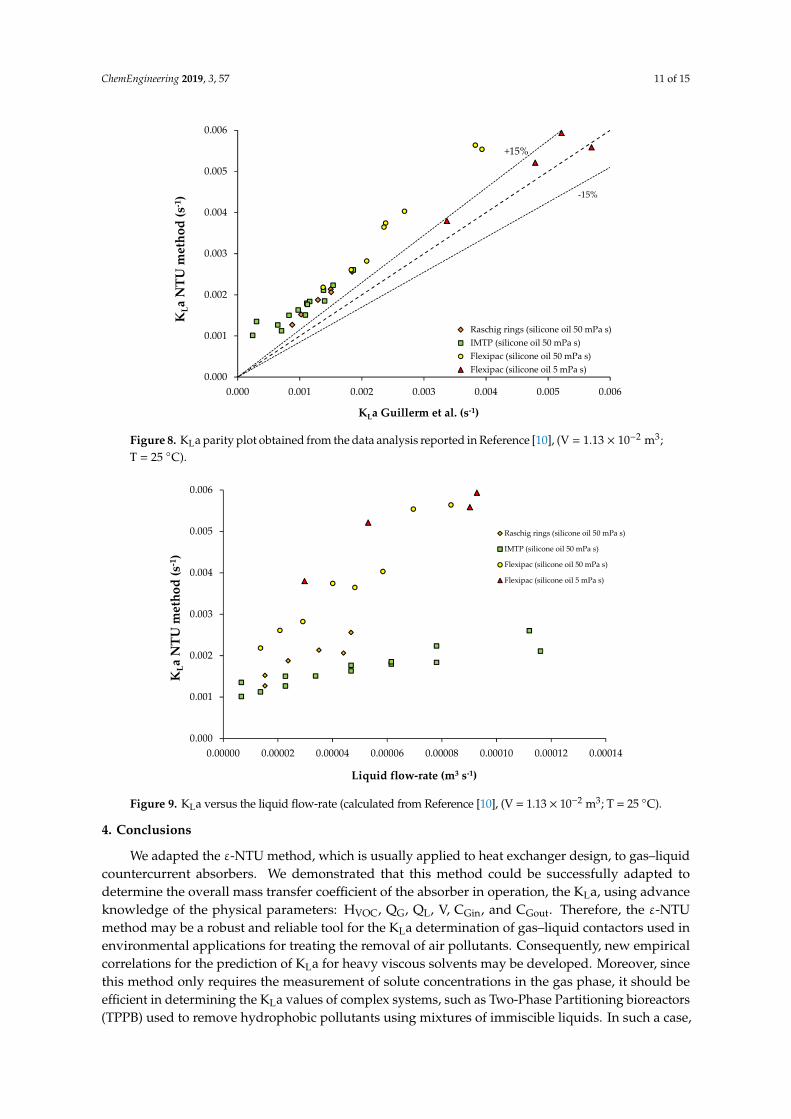
From Figure 8, it appears that the KLa parity plot is validated for the solvent with low dynamicviscosity (5 mPa s). Conversely, for the solvent with the high dynamic viscosity (50 mPa s), the KLadetermined using the ε-NTU method was usually 30% higher than the values calculated usingEquation (20). According to this equation, the KLa determination required the measurement of soluteconcentrations in the gas phase and in the liquid phase. As the concentration measurement of a solutein a viscous fluid could be relatively inaccurate, the KLa determination using Equation (20) shouldbe considered cautiously. Consequently, the KLa determination using the ε-NTU method shouldbe preferred, since only the inlet and outlet gaseous concentrations are needed. Results from thisstudy also confirmed that the viscosity of the liquid, as well as the type of packing material fillingthe column, has a considerable impact on the volumetric mass transfer coefficient of the operatingabsorber (Figure 9).
ChemEngineering 2019, 3, 57 11 of 15
ChemEngineering 2019, 3, x FOR PEER REVIEW 12 of 16
Figure 8. KLa parity plot obtained from the data analysis reported in Reference [10], (V = 1.13 × 10⁻² m3; T = 25 °C).
Figure 9. KLa versus the liquid flow-rate (calculated from Reference [10], (V = 1.13 × 10⁻² m3; T = 25 °C).
4. Conclusions
We adapted the ε-NTU method, which is usually applied to heat exchanger design, to gas–liquid countercurrent absorbers. We demonstrated that this method could be successfully adapted to determine the overall mass transfer coefficient of the absorber in operation, the KLa, using advance knowledge of the physical parameters: HVOC, QG, QL, V, CGin, and CGout. Therefore, the ε-NTU method may be a robust and reliable tool for the KLa determination of gas–liquid contactors used in environmental applications for treating the removal of air pollutants. Consequently, new empirical correlations for the prediction of KLa for heavy viscous solvents may be developed. Moreover, since
0.000
0.001
0.002
0.003
0.004
0.005
0.006
0.000 0.001 0.002 0.003 0.004 0.005 0.006
KLa
NTU
met
hod
(s-1
)
KLa Guillerm et al. (s-1)
Série3Série7Série4Raschig rings (silicone oil 50 mPa s)IMTP (silicone oil 50 mPa s)Flexipac (silicone oil 50 mPa s)Flexipac (silicone oil 5 mPa s)
+15%
-15%
0.000
0.001
0.002
0.003
0.004
0.005
0.006
0.00000 0.00002 0.00004 0.00006 0.00008 0.00010 0.00012 0.00014
KLa
NTU
met
hod
(s-1
)
Liquid flow-rate (m3 s-1)
Raschig rings (silicone oil 50 mPa s)
IMTP (silicone oil 50 mPa s)
Flexipac (silicone oil 50 mPa s)
Flexipac (silicone oil 5 mPa s)
Figure 8. KLa parity plot obtained from the data analysis reported in Reference [10], (V = 1.13 × 10⁻² m3;T = 25 C).
ChemEngineering 2019, 3, x FOR PEER REVIEW 12 of 16
Figure 8. KLa parity plot obtained from the data analysis reported in Reference [10], (V = 1.13 × 10⁻² m3; T = 25 °C).
Figure 9. KLa versus the liquid flow-rate (calculated from Reference [10], (V = 1.13 × 10⁻² m3; T = 25 °C).
4. Conclusions
We adapted the ε-NTU method, which is usually applied to heat exchanger design, to gas–liquid countercurrent absorbers. We demonstrated that this method could be successfully adapted to determine the overall mass transfer coefficient of the absorber in operation, the KLa, using advance knowledge of the physical parameters: HVOC, QG, QL, V, CGin, and CGout. Therefore, the ε-NTU method may be a robust and reliable tool for the KLa determination of gas–liquid contactors used in environmental applications for treating the removal of air pollutants. Consequently, new empirical correlations for the prediction of KLa for heavy viscous solvents may be developed. Moreover, since
0.000
0.001
0.002
0.003
0.004
0.005
0.006
0.000 0.001 0.002 0.003 0.004 0.005 0.006
KLa
NTU
met
hod
(s-1
)
KLa Guillerm et al. (s-1)
Série3Série7Série4Raschig rings (silicone oil 50 mPa s)IMTP (silicone oil 50 mPa s)Flexipac (silicone oil 50 mPa s)Flexipac (silicone oil 5 mPa s)
+15%
-15%
0.000
0.001
0.002
0.003
0.004
0.005
0.006
0.00000 0.00002 0.00004 0.00006 0.00008 0.00010 0.00012 0.00014
KLa
NTU
met
hod
(s-1
)
Liquid flow-rate (m3 s-1)
Raschig rings (silicone oil 50 mPa s)
IMTP (silicone oil 50 mPa s)
Flexipac (silicone oil 50 mPa s)
Flexipac (silicone oil 5 mPa s)
Figure 9. KLa versus the liquid flow-rate (calculated from Reference [10], (V = 1.13 × 10⁻² m3; T = 25 C).
4. Conclusions
We adapted the ε-NTU method, which is usually applied to heat exchanger design, to gas–liquidcountercurrent absorbers. We demonstrated that this method could be successfully adapted todetermine the overall mass transfer coefficient of the absorber in operation, the KLa, using advanceknowledge of the physical parameters: HVOC, QG, QL, V, CGin, and CGout. Therefore, the ε-NTUmethod may be a robust and reliable tool for the KLa determination of gas–liquid contactors used inenvironmental applications for treating the removal of air pollutants. Consequently, new empiricalcorrelations for the prediction of KLa for heavy viscous solvents may be developed. Moreover, sincethis method only requires the measurement of solute concentrations in the gas phase, it should beefficient in determining the KLa values of complex systems, such as Two-Phase Partitioning bioreactors(TPPB) used to remove hydrophobic pollutants using mixtures of immiscible liquids. In such a case,
ChemEngineering 2019, 3, 57 12 of 15
the main difficulty lies in the knowledge of the HVOC. As a result, the ε-NTU method must be combinedwith the “equivalent absorption capacity” concept [12,13], thereby enabling calculation of the physicalproperties of the mixture [14].
Funding: This research received no external funding.
Conflicts of Interest: The author declares no conflict of interest.
Nomenclature
absorbera specific interfacial area (m−1)A absorption factorC concentration (mol m−3)EBRT Empty Bed Residence Time (s)H Henry coefficientkG, kL local mass transfer coefficients (m s−1)KGa, KLa overall mass transfer coefficients (s−1)NTU Number of Transfer UnitsQ flow-rate (m3 s−1)V packing volume (m3)Z packing height (m)Greek lettersδ film thickness (m)ε effectivenessΩ cross sectional area (m2)φ molar flux (mol m−3 s−1)SubscriptsG gasin inletL liquidMax maximumout outletVOC Volatile Organic Compoundheat exchanger, Table 1A heat-transfer area (m2)C heat capacity rate of the fluid = M Cp (W K−1)Cp specific heat capacity (J kg−1 K−1)M flow rate (kg s−1)NTU Number of Transfer UnitsT temperature (K)U heat transfer coefficient (W m−2 K−1)Greek letters∆TML log mean temperature difference (K)ε effectivenessφ power, heat transferred per unit time (W)Subscriptsc coldh hotin inletMax maximumMin minimumout outlet
ChemEngineering 2019, 3, 57 13 of 15
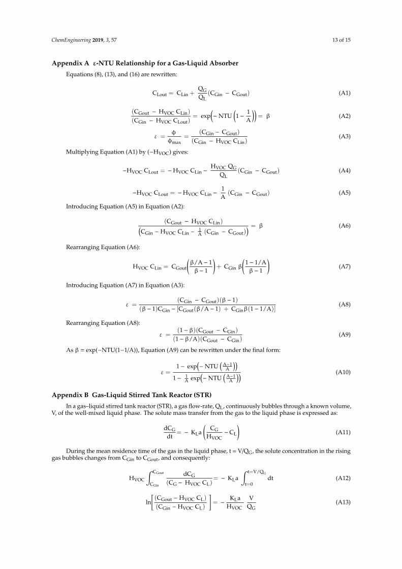
Appendix A ε-NTU Relationship for a Gas-Liquid Absorber
Equations (8), (13), and (16) are rewritten:
CLout = CLin +QGQL
(CGin − CGout) (A1)
(CGout − HVOC CLin)
(CGin − HVOC CLout)= exp
(− NTU
(1−
1A
))= β (A2)
ε =φ
φmax=
(CGin − CGout)
(CGin − HVOC CLin)(A3)
Multiplying Equation (A1) by (−HVOC) gives:
−HVOC CLout = −HVOC CLin −HVOC QG
QL(CGin − CGout) (A4)
−HVOC CLout = −HVOC CLin −1A
(CGin − CGout) (A5)
Introducing Equation (A5) in Equation (A2):
(CGout − HVOC CLin)(CGin − HVOC CLin −
1A (CGin − CGout)
) = β (A6)
Rearranging Equation (A6):
HVOC CLin = CGout
(β/A− 1β− 1
)+ CGin β
(1− 1/Aβ− 1
)(A7)
Introducing Equation (A7) in Equation (A3):
ε =(CGin − CGout)(β− 1)
(β− 1)CGin − [CGout(β/A− 1) + CGinβ(1− 1/A)](A8)
Rearranging Equation (A8):
ε =(1−β)(CGout − CGin)
(1−β/A)(CGout − CGin)(A9)
As β = exp(−NTU(1−1/A)), Equation (A9) can be rewritten under the final form:
ε =1− exp
(− NTU
(A−1
A
))1− 1
A exp(− NTU
(A−1
A
)) (A10)
Appendix B Gas-Liquid Stirred Tank Reactor (STR)
In a gas–liquid stirred tank reactor (STR), a gas flow-rate, QL, continuously bubbles through a known volume,V, of the well-mixed liquid phase. The solute mass transfer from the gas to the liquid phase is expressed as:
dCGdt
= − KLa(
CGHVOC
−CL
)(A11)
During the mean residence time of the gas in the liquid phase, t = V/QG, the solute concentration in the risinggas bubbles changes from CGin to CGout, and consequently:
HVOC
∫ CGout
CGin
dCG
(CG − HVOC CL)= − KLa
∫ t=V/QG
t=0dt (A12)
ln[(CGout − HVOC CL)
(CGin − HVOC CL)
]= −
KLaHVOC
VQG
(A13)

ChemEngineering 2019, 3, 57 14 of 15
Defining NTU = (KLa V)/(HVOC QG), Equation (A13) becomes:
CGout = HVOC CL (1− exp(−NTU)) + CGin exp (−NTU) (A14)
Moreover, the molar flux φ of the transferred solute is:
φ =QGV
(CGin − CGout) (A15)
Introducing the expression of CGout (Equation (A14)) in Equation (A15) gives:
φ =QGV
(1− exp(−NTU))(CGin − HVOC CL) (A16)
where the term (1−exp(−NTU)) is the solute fraction that can be transferred from the gas phase to the liquid phase.Basically, for industrial applications, the initial concentration of the liquid phase is CL = 0. Consequently:
φ =QGV
(1− exp(−NTU)) CGin (A17)
According to the NTU expression, the maximum solute fraction that can be transferred is obtained for a longresidence time of the gas phase in the liquid phase (i.e., using a large liquid volume and a small gas flow-rate). Inthat case, the NTU is significantly higher than 1 and exp(−NTU) tends to 0. As a result:
φmax =QGV
CGin (A18)
The effectiveness of the STR is then:
ε =φ
φmax= 1 − exp(− NTU ) (A19)
References
1. Biard, P.-F.; Couvert, A.; Giraudet, S. Volatile organic compounds absorption in packed column: Theoreticalassessment of water, DEHA and PDMS 50 as absorbents. J. Ind. Eng. Chem. 2018, 59, 70–78. [CrossRef]
2. Dumont, E.; Delmas, H. Mass transfer enhancement of gas absorption in oil-in-water systems: A review.Chem. Eng. Process. Process Intensif. 2003, 42, 419–438. [CrossRef]
3. Mackowiak, J. Fluid Dynamics of Packed Columns: Principles of the Fluid Dynamic Design of Columns for Gas/Liquidand Liquid/Liquid Systems; Chemische Technik/Verfahrenstechnik; Springer: Berlin/Heidelberg, Germany,2010; ISBN 978-3-540-88780-5.
4. Fair, J.; Steinmeyer, D.; Penney, W.; Corcker, B. Gas absorption and gas-liquid system design. In Perry’sChemical Engineers’ Handbook, 8th ed.; Perry, R.H., Green, D.W., Eds.; McGraw-Hill: New York, NY, USA,2008; pp. 14-1–14-98.
5. Sinnott, R. Coulson and Richardson’s Chemical Engineering Volume 6 (Design); Pergamon Press: Oxford, UK,1994; Volume 6, ISBN 0-08-041865-1.
6. Bourgois, D.; Vanderschuren, J.; Thomas, D. Study of mass transfer of VOCs into viscous solvents in apilot-scale cables-bundle scrubber. Chem. Eng. J. 2009, 145, 446–452. [CrossRef]
7. Garcia-Ochoa, F.; Gomez, E. Bioreactor scale-up and oxygen transfer rate in microbial processes: An overview.Biotechnol. Adv. 2009, 27, 153–176. [CrossRef] [PubMed]
8. Russell, T.W.F.; Robinson, A.S.; Wagner, N.J. Mass and Heat Transfer: Analysis of Mass Contactors and HeatExchangers; Cambridge Series in Chemical Engineering; Cambridge University Press: Cambridge, UK;New York, NY, USA, 2008; ISBN 978-0-521-88670-3.
9. Staudinger, J.; Roberts, P.V. A critical compilation of Henry’s law constant temperature dependence relationsfor organic compounds in dilute aqueous solutions. Chemosphere 2001, 44, 561–576. [CrossRef]
10. Guillerm, M.; Couvert, A.; Amrane, A.; Norrant, E.; Lesage, N.; Dumont, É. Absorption of toluene in siliconeoil: Effect of the solvent viscosity on hydrodynamics and mass transfer. Chem. Eng. Res. Des. 2016, 109,32–40. [CrossRef]
ChemEngineering 2019, 3, 57 15 of 15
11. Heymes, F.; Manno Demoustier, P.; Charbit, F.; Louis Fanlo, J.; Moulin, P. Hydrodynamics and mass transferin a packed column: Case of toluene absorption with a viscous absorbent. Chem. Eng. Sci. 2006, 61,5094–5106. [CrossRef]
12. Dumont, E.; Darracq, G.; Couvert, A.; Couriol, C.; Amrane, A.; Thomas, D.; Andrès, Y.; Le Cloirec, P. Determinationof partition coefficients of three volatile organic compounds (dimethylsulphide, dimethyldisulphide and toluene)in water/silicone oil mixtures. Chem. Eng. J. 2010, 162, 927–934. [CrossRef]
13. Dumont, E.; Darracq, G.; Couvert, A.; Couriol, C.; Amrane, A.; Thomas, D.; Andrès, Y.; Le Cloirec, P. VOCabsorption in a countercurrent packed-bed column using water/silicone oil mixtures: Influence of silicone oilvolume fraction. Chem. Eng. J. 2011, 168, 241–248. [CrossRef]
14. Dumont, É. Mass Transfer in Multiphasic Gas/Liquid/Liquid Systems. KLa Determination Using theEffectiveness-Number of Transfer Unit Method. Processes 2018, 6, 156. [CrossRef]
© 2019 by the author. Licensee MDPI, Basel, Switzerland. This article is an open accessarticle distributed under the terms and conditions of the Creative Commons Attribution(CC BY) license (http://creativecommons.org/licenses/by/4.0/).