Embed Size (px)
Citation preview
J. Webster (ed.), Wiley Encyclopedia of Electrical and Electronics EngineeringCopyright c© 1999 John Wiley & Sons, Inc.
HYDROGEN ENERGY SYSTEMS
Utilization of fossil fuels appears to be causing global problems such as the greenhouse effect, ozone layerdepletion, and acid rain and pollution, which are posing great danger to our environment and eventually tolife on our planet. Many engineers and scientists agree that a solution to all these global problems would beto replace the existing fossil fuel system with the hydrogen energy system. Hydrogen is a very efficient andclean fuel. Its combustion produces no greenhouse gases, no ozone layer-depleting chemicals, little or no acidrain ingredients, and no pollution. Hydrogen, produced from renewable (solar) energy sources, would providea permanent energy system, which we may never have to change.
However, other energy systems have been proposed for the postpetroleum era such as the synthetic fossilfuel system. In this system, synthetic gasoline and synthetic natural gas are to be produced using the abundantdeposits of coal. In a way, this could ensure the continuation of the present fossil fuel system.
The two possible energy systems for the postfossil fuel era (solar hydrogen energy system and syntheticfossil fuel system) are compared with the present fossil fuel system by taking into consideration productioncosts, environmental damage, and utilization efficiencies. Results indicate that the solar hydrogen energysystem is the best energy system to guarantee a sustainable future.
Under normal conditions, hydrogen is a gas, and for many applications it will be used in gaseous form, justlike natural gas. Wherever space considerations are important, such as in aerospace applications, hydrogen isused in liquid form. If space saving becomes the number one priority, as in the case with the earth-to-stationeryorbit single-stage transport, then slush hydrogen could be the best answer.
Fossil Fuels
After the invention of the steam engine in the 1860s, when advances brought about by the Industrial Revolutionstarted to replace humans’ and beasts’ toil with nature’s energy sources, a bright future seemed to be certainfor humankind. More and more of nature’s energy, initially in the form of wood and coal and later as oil andnatural gas, was being harnessed for the benefit of humans. This resulted in mass production of goods with acorresponding reduction in prices, thus raising living standards. Communities asked for factories, railroads,highways, seaports, and airports. This meant more jobs, more income, more goods, and more services. Theworld’s standard of living was rising. When the Industrial Revolution started, the annual gross world productper capita was in some tens of dollars; today, it is about $6600 and rising exponentially.
Fossil fuels, which fed this amazing economic growth, were the medicine to cure deprivation, but it wasan untested medicine. As humans consumed more and more fossil fuels, two important predicaments startedto emerge: (1) fossil fuels would be depleted in a foreseeable future, and (2) fossil fuels and their combustionproducts were causing global environmental problems.
Depletion. The demand for energy continues to rise for two main reasons: (a) the continuing increasein world population and (b) the growing demand by the developing countries in order to improve their livingstandards. At the present time, a large portion (about 70%) of the world energy demand is met by fluid fossil
1
2 HYDROGEN ENERGY SYSTEMS
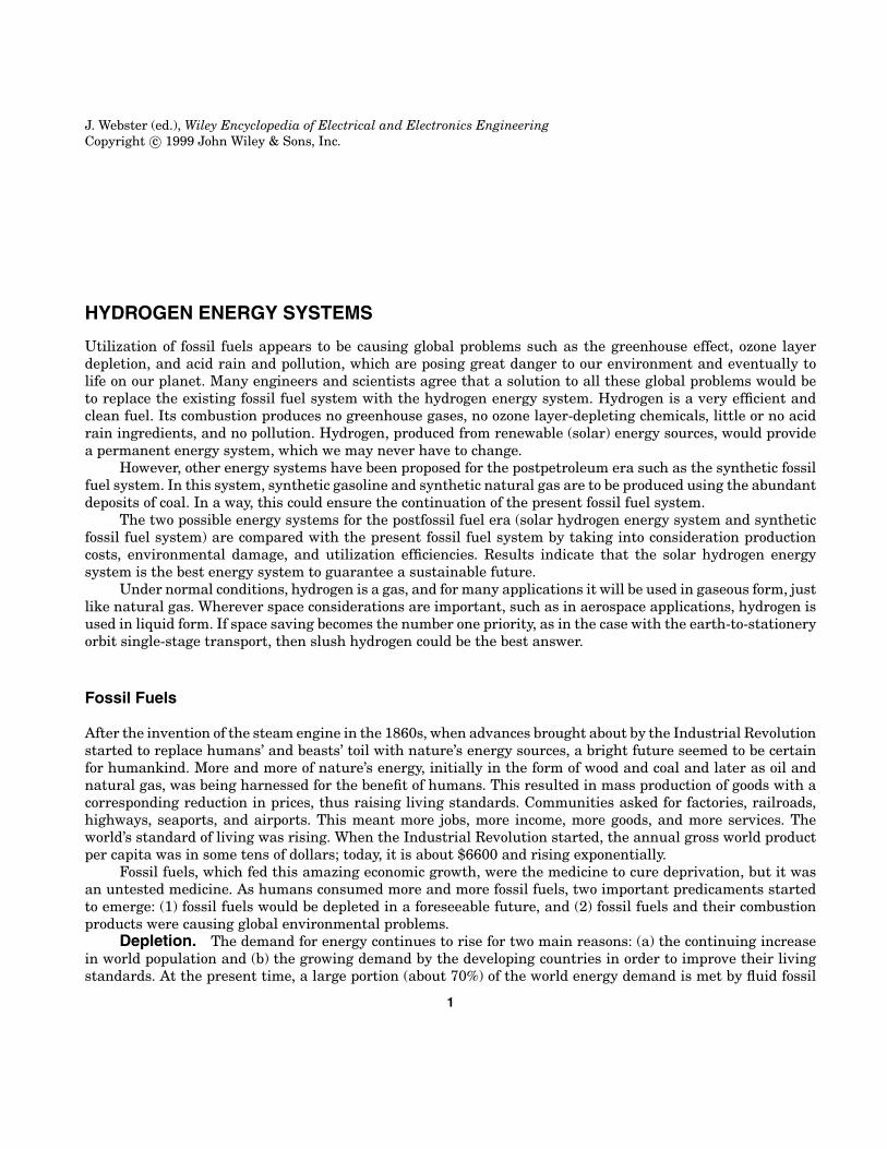
Fig. 1. Estimates of world fossil fuel production.
fuels (petroleum and natural gas) because of the availability of these resources and their convenience of use.However, it is expected that the world fluid fossil fuel production will soon peak and thereafter begin to decrease(1,2,3,4). Figure 1 shows estimates of the production rates of fossil fuels and the world demand. It can be seenthat the fluid fossil fuel production worldwide will continue to rise for the next 15 years and then will startto decrease. The coal production—because of obvious environmental reasons—is expected to remain nearlyconstant for the next decade and then start to decrease.
Meanwhile, as a result of the growing world population and the desire of people to better their livingstandards, the world demand for fluid fuels is rising (Fig. 1). It is expected that the world population (which is5.88 billion as of 1998 and rising at 1.5% per year) growth will slow down and reach about 10 to 12 billion by theend of the next century (5). Consequently, the world demand for fluid fuels will slow down and reach around 1.6× 10¹² GJ per year (1 GJ of energy is approximately equal to the energy contained in 3.4 gallons of petroleum).There will be a growing gap, starting within the next 10 years, between the demand and production of fluidfuels.
Environmental Damage. The second predicament involving fossil fuels is the environmental damagebeing caused by their combustion products. Technologies for fossil fuel extraction, transportation, processing,and particularly their end use (combustion) have harmful effects on the environment, which cause direct andindirect negative effects on the economy. Excavation of coal devastates the land, which has to be reclaimed and isout of use for several years. During the extraction, transportation, and storage of oil and gas, spills and leakages,which cause water and air pollution, occur. Refining processes also have an environmental impact. However,most of the fossil fuel environmental impact occurs during end use. End use of all fossil fuels is combustion,irrespective of the final purpose (heating, electricity production, or motive power for transportation). The mainconstituents of fossil fuels are carbon and hydrogen in addition to some other ingredients, which are originallyin the fuel (sulfur) or are added during refining (lead, alcohols). Combustion of fossil fuels produces variousgases (COx, SOx, NOx, CH), soot and ash, droplets of tar, and other organic compounds, which are all releasedinto the atmosphere and cause air pollution. Air pollution may be defined as the presence of some gases andparticulates that are not a natural constituent of the atmosphere, or the presence of natural constituents in
HYDROGEN ENERGY SYSTEMS 3
an abnormal concentration. Air pollution causes damage to human health, animals, crops, and structures, inaddition to reducing visibility, among other problems.
Once in the atmosphere, triggered by sunlight or by mixing with water and other atmospheric compounds,these primary pollutants may undergo chemical reactions, change their form, and become secondary pollutants,like ozone, aerosols, peroxyacyl nitrates, and various acids. Precipitation of sulfur and nitrogen oxides, whichhave dissolved in clouds and in rain droplets to form sulfuric and nitric acids is called acid rain, but alsoacid dew, acid fog, and acid snow have been recorded. Carbon dioxide in equilibrium with water producesweak carbonic acid. Acid deposition (wet or dry) causes soil and water acidification, resulting in damage to theaquatic and terrestrial ecosystems, affecting humans, animals, vegetation, and structures.
The remaining products of combustion in the atmosphere, mainly carbon dioxide, together with otherso-called greenhouse gases (methane, nitrogen oxides, and chlorofluorocarbons), result in thermal changes byabsorbing the infrared energy the Earth radiates into the atmosphere and by reradiating some back to Earth,causing global temperatures to increase. The effects of temperature increase are melting of the ice caps, sealevel rise, and climate change, which includes heat waves, droughts, floods, stronger storms, and more wildfires.
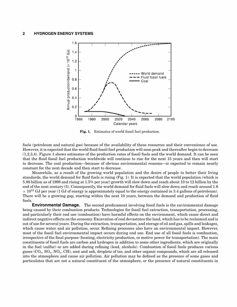
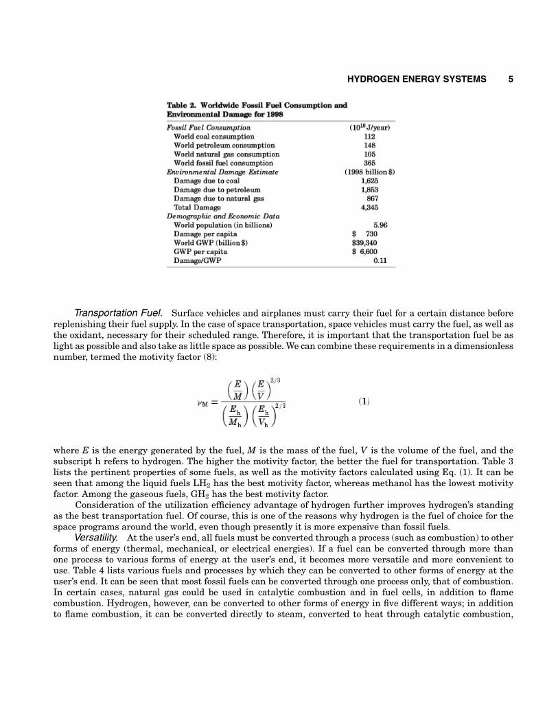
Using the studies by scores of environmental scientists, these stated damages have been calculated for thedifferent types of fossil fuels listed (6). Table 1 presents the results for each type of damage (in 1998 US dollars).It can be seen that the environmental damage for coal is $14.51/GJ of coal consumed, for petroleum is $12.52/GJof petroleum consumed, for natural gas $8.26/GJ of natural gas consumed, and the weighted mean damage inthe world is $12.05/GJ of fossil fuel consumption. These damage costs are not included in the prices of fossilfuels, but they are paid for by the people directly or indirectly through taxes, health expenditures, insurancepremiums, and a reduced quality of living. In other words, today’s fossil fuels are heavily subsidized. If therespective environmental damages were included in the fossil fuel prices, it would force earlier introduction ofcleaner fuels, such as hydrogen, with many benefits to the economy and the environment.
In order to see the worldwide dimensions of the fossil fuel environmental damage, Table 2 has beenprepared. Note that 37% of the total damage is caused by coal, whereas the coal consumption is 31% of thetotal fossil fuel consumption. On the other hand, only 20% of the damage is caused by natural gas, which hasa market share of 29%. It is clear that increasing the natural gas consumption at the expense of coal andpetroleum will be environmentally beneficial. This would also pave the way for greater public acceptance ofgaseous fuels, which may result in a smoother change to hydrogen, also a gaseous fuel.
Note also from Table 2 that the annual worldwide environmental damage caused by fossil fuels is $4345billion, or 11% of the gross world product. This is a very large figure. Conversion to a cleaner fuel, such ashydrogen, would enable the world to save this enormous sum and perhaps use it to improve the quality of lifeworldwide.
New Energy System
Because of the environmental problems fossil fuels are causing, energy researchers are looking at all possiblesources of energy to replace these fuels. There are quite a number of primary energy sources, such as ther-monuclear energy, nuclear breeders, solar energy, wind energy, hydropower, geothermal energy, ocean currents,tides, and waves, that are available. At the consumer end, about one-quarter of the primary energy is used aselectricity and three-quarters is used as fuel. The primary energy sources already mentioned must thereforebe converted to these energy carriers needed by the consumer. In contrast with fossil fuels, none of the newprimary energy sources can directly be used as a fuel (e.g., for air and land transportation). Consequently, theymust be used to manufacture a fuel or fuels as well as to generate electricity.
Comparison of Fuels. Because we need to manufacture a fuel for the post fossil fuel era, we are in aposition to select the best possible fuel. There are many candidates, such as synthetic gasoline, synthetic naturalgas (methane), methanol, ethanol, and hydrogen. The fuel of choice must satisfy the following conditions (7):
4 HYDROGEN ENERGY SYSTEMS
• It must be convenient for transportation;• It must be versatile or convert with ease to other energy forms at the user end;• It must have high utilization efficiency; and• It must be safe to use.
In addition, the resulting energy system must be environmentally compatible and economical.
HYDROGEN ENERGY SYSTEMS 5
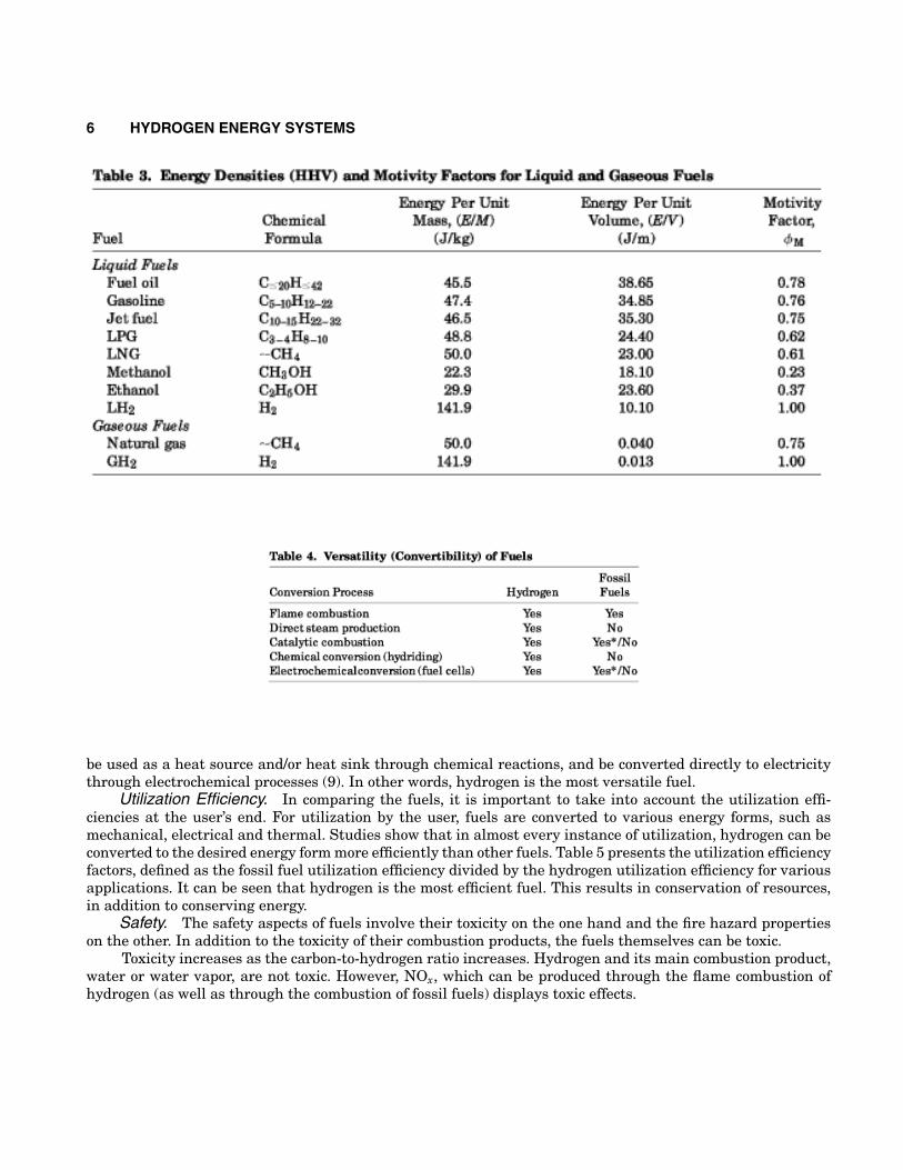
Transportation Fuel. Surface vehicles and airplanes must carry their fuel for a certain distance beforereplenishing their fuel supply. In the case of space transportation, space vehicles must carry the fuel, as well asthe oxidant, necessary for their scheduled range. Therefore, it is important that the transportation fuel be aslight as possible and also take as little space as possible. We can combine these requirements in a dimensionlessnumber, termed the motivity factor (8):
where E is the energy generated by the fuel, M is the mass of the fuel, V is the volume of the fuel, and thesubscript h refers to hydrogen. The higher the motivity factor, the better the fuel for transportation. Table 3lists the pertinent properties of some fuels, as well as the motivity factors calculated using Eq. (1). It can beseen that among the liquid fuels LH2 has the best motivity factor, whereas methanol has the lowest motivityfactor. Among the gaseous fuels, GH2 has the best motivity factor.
Consideration of the utilization efficiency advantage of hydrogen further improves hydrogen’s standingas the best transportation fuel. Of course, this is one of the reasons why hydrogen is the fuel of choice for thespace programs around the world, even though presently it is more expensive than fossil fuels.
Versatility. At the user’s end, all fuels must be converted through a process (such as combustion) to otherforms of energy (thermal, mechanical, or electrical energies). If a fuel can be converted through more thanone process to various forms of energy at the user’s end, it becomes more versatile and more convenient touse. Table 4 lists various fuels and processes by which they can be converted to other forms of energy at theuser’s end. It can be seen that most fossil fuels can be converted through one process only, that of combustion.In certain cases, natural gas could be used in catalytic combustion and in fuel cells, in addition to flamecombustion. Hydrogen, however, can be converted to other forms of energy in five different ways; in additionto flame combustion, it can be converted directly to steam, converted to heat through catalytic combustion,
6 HYDROGEN ENERGY SYSTEMS
be used as a heat source and/or heat sink through chemical reactions, and be converted directly to electricitythrough electrochemical processes (9). In other words, hydrogen is the most versatile fuel.
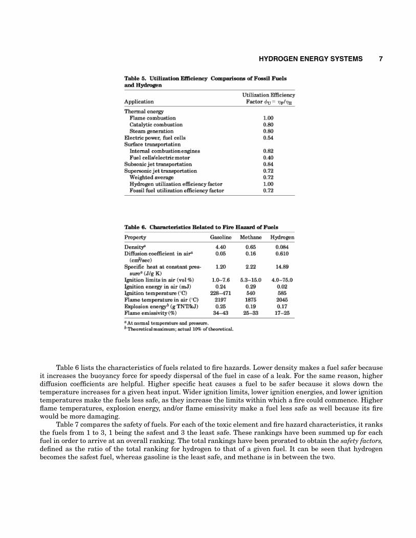
Utilization Efficiency. In comparing the fuels, it is important to take into account the utilization effi-ciencies at the user’s end. For utilization by the user, fuels are converted to various energy forms, such asmechanical, electrical and thermal. Studies show that in almost every instance of utilization, hydrogen can beconverted to the desired energy form more efficiently than other fuels. Table 5 presents the utilization efficiencyfactors, defined as the fossil fuel utilization efficiency divided by the hydrogen utilization efficiency for variousapplications. It can be seen that hydrogen is the most efficient fuel. This results in conservation of resources,in addition to conserving energy.
Safety. The safety aspects of fuels involve their toxicity on the one hand and the fire hazard propertieson the other. In addition to the toxicity of their combustion products, the fuels themselves can be toxic.
Toxicity increases as the carbon-to-hydrogen ratio increases. Hydrogen and its main combustion product,water or water vapor, are not toxic. However, NOx, which can be produced through the flame combustion ofhydrogen (as well as through the combustion of fossil fuels) displays toxic effects.
HYDROGEN ENERGY SYSTEMS 7
Table 6 lists the characteristics of fuels related to fire hazards. Lower density makes a fuel safer becauseit increases the buoyancy force for speedy dispersal of the fuel in case of a leak. For the same reason, higherdiffusion coefficients are helpful. Higher specific heat causes a fuel to be safer because it slows down thetemperature increases for a given heat input. Wider ignition limits, lower ignition energies, and lower ignitiontemperatures make the fuels less safe, as they increase the limits within which a fire could commence. Higherflame temperatures, explosion energy, and/or flame emissivity make a fuel less safe as well because its firewould be more damaging.
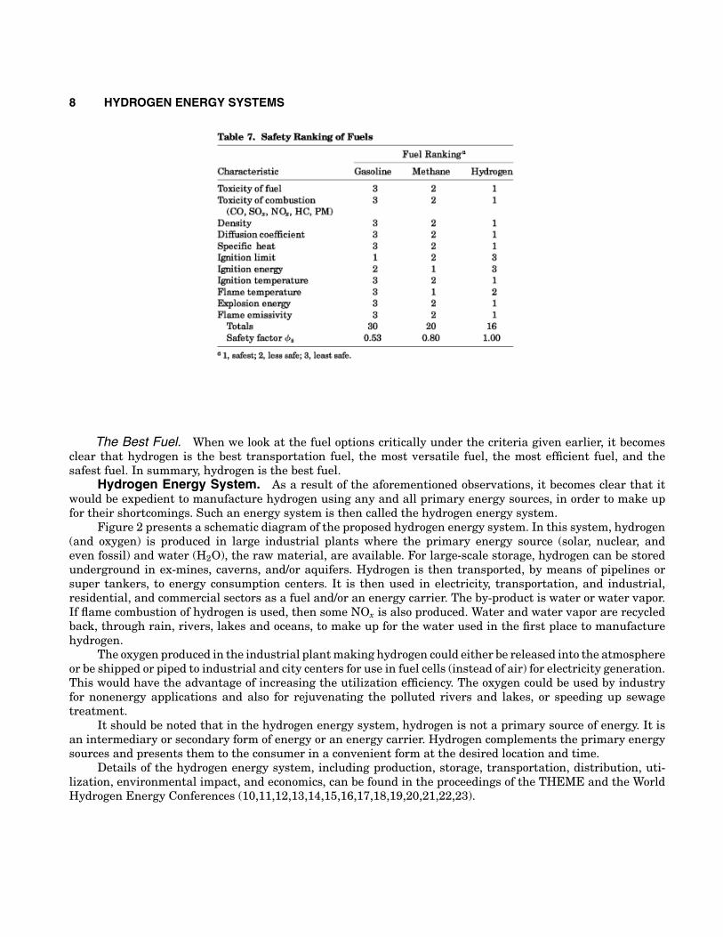
Table 7 compares the safety of fuels. For each of the toxic element and fire hazard characteristics, it ranksthe fuels from 1 to 3, 1 being the safest and 3 the least safe. These rankings have been summed up for eachfuel in order to arrive at an overall ranking. The total rankings have been prorated to obtain the safety factors,defined as the ratio of the total ranking for hydrogen to that of a given fuel. It can be seen that hydrogenbecomes the safest fuel, whereas gasoline is the least safe, and methane is in between the two.
8 HYDROGEN ENERGY SYSTEMS
The Best Fuel. When we look at the fuel options critically under the criteria given earlier, it becomesclear that hydrogen is the best transportation fuel, the most versatile fuel, the most efficient fuel, and thesafest fuel. In summary, hydrogen is the best fuel.
Hydrogen Energy System. As a result of the aforementioned observations, it becomes clear that itwould be expedient to manufacture hydrogen using any and all primary energy sources, in order to make upfor their shortcomings. Such an energy system is then called the hydrogen energy system.
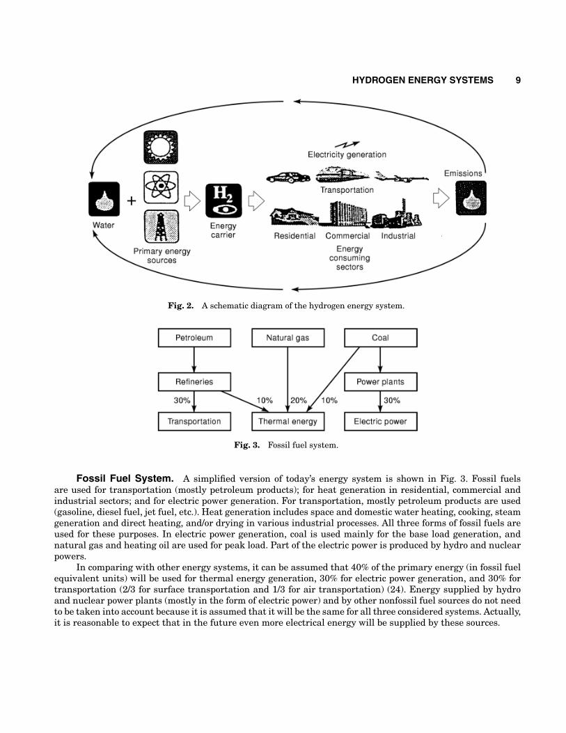
Figure 2 presents a schematic diagram of the proposed hydrogen energy system. In this system, hydrogen(and oxygen) is produced in large industrial plants where the primary energy source (solar, nuclear, andeven fossil) and water (H2O), the raw material, are available. For large-scale storage, hydrogen can be storedunderground in ex-mines, caverns, and/or aquifers. Hydrogen is then transported, by means of pipelines orsuper tankers, to energy consumption centers. It is then used in electricity, transportation, and industrial,residential, and commercial sectors as a fuel and/or an energy carrier. The by-product is water or water vapor.If flame combustion of hydrogen is used, then some NOx is also produced. Water and water vapor are recycledback, through rain, rivers, lakes and oceans, to make up for the water used in the first place to manufacturehydrogen.
The oxygen produced in the industrial plant making hydrogen could either be released into the atmosphereor be shipped or piped to industrial and city centers for use in fuel cells (instead of air) for electricity generation.This would have the advantage of increasing the utilization efficiency. The oxygen could be used by industryfor nonenergy applications and also for rejuvenating the polluted rivers and lakes, or speeding up sewagetreatment.
It should be noted that in the hydrogen energy system, hydrogen is not a primary source of energy. It isan intermediary or secondary form of energy or an energy carrier. Hydrogen complements the primary energysources and presents them to the consumer in a convenient form at the desired location and time.
Details of the hydrogen energy system, including production, storage, transportation, distribution, uti-lization, environmental impact, and economics, can be found in the proceedings of the THEME and the WorldHydrogen Energy Conferences (10,11,12,13,14,15,16,17,18,19,20,21,22,23).
HYDROGEN ENERGY SYSTEMS 9
Fig. 2. A schematic diagram of the hydrogen energy system.
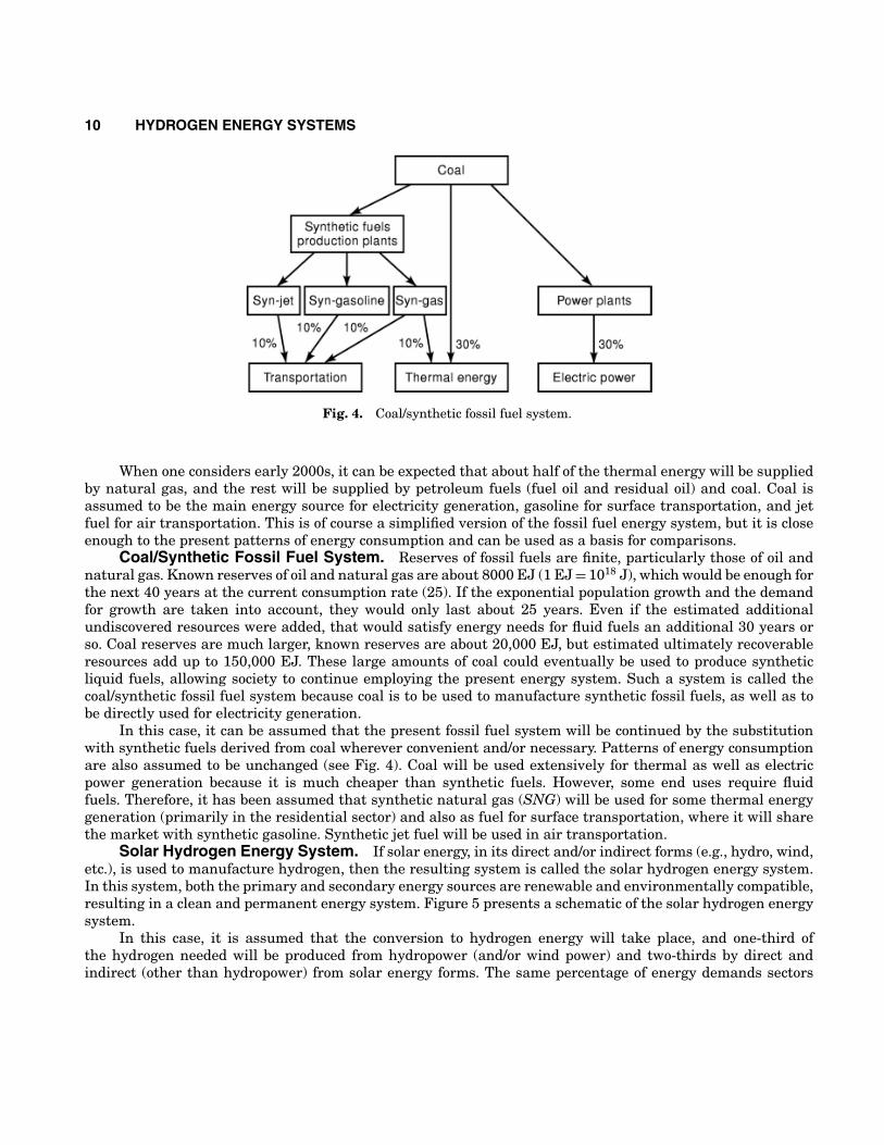
Fig. 3. Fossil fuel system.
Fossil Fuel System. A simplified version of today’s energy system is shown in Fig. 3. Fossil fuelsare used for transportation (mostly petroleum products); for heat generation in residential, commercial andindustrial sectors; and for electric power generation. For transportation, mostly petroleum products are used(gasoline, diesel fuel, jet fuel, etc.). Heat generation includes space and domestic water heating, cooking, steamgeneration and direct heating, and/or drying in various industrial processes. All three forms of fossil fuels areused for these purposes. In electric power generation, coal is used mainly for the base load generation, andnatural gas and heating oil are used for peak load. Part of the electric power is produced by hydro and nuclearpowers.
In comparing with other energy systems, it can be assumed that 40% of the primary energy (in fossil fuelequivalent units) will be used for thermal energy generation, 30% for electric power generation, and 30% fortransportation (2/3 for surface transportation and 1/3 for air transportation) (24). Energy supplied by hydroand nuclear power plants (mostly in the form of electric power) and by other nonfossil fuel sources do not needto be taken into account because it is assumed that it will be the same for all three considered systems. Actually,it is reasonable to expect that in the future even more electrical energy will be supplied by these sources.
10 HYDROGEN ENERGY SYSTEMS
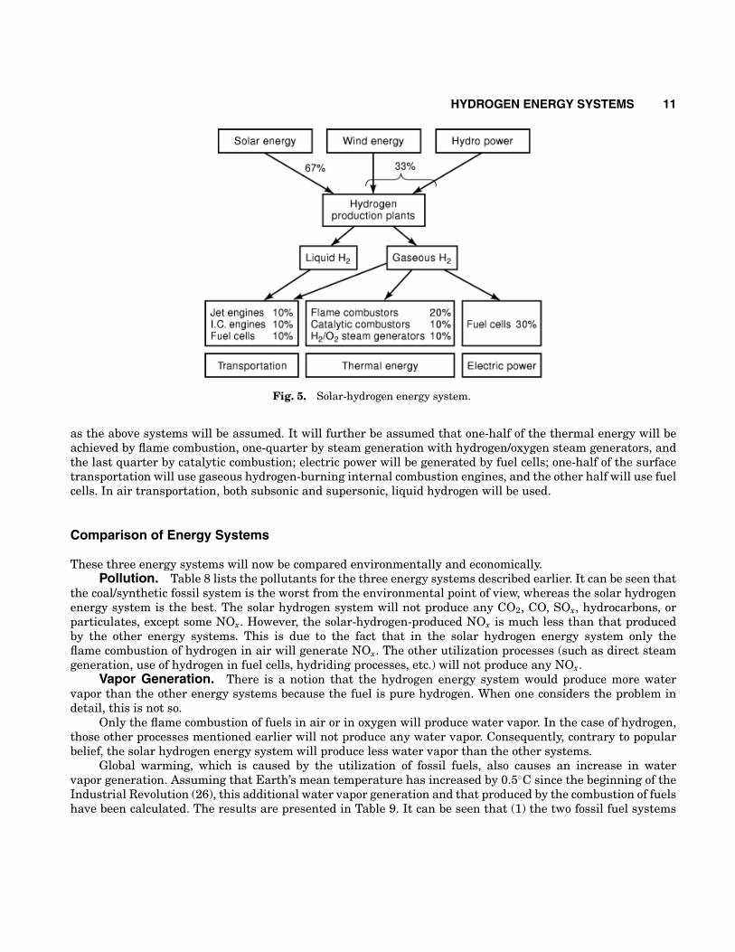
Fig. 4. Coal/synthetic fossil fuel system.
When one considers early 2000s, it can be expected that about half of the thermal energy will be suppliedby natural gas, and the rest will be supplied by petroleum fuels (fuel oil and residual oil) and coal. Coal isassumed to be the main energy source for electricity generation, gasoline for surface transportation, and jetfuel for air transportation. This is of course a simplified version of the fossil fuel energy system, but it is closeenough to the present patterns of energy consumption and can be used as a basis for comparisons.
Coal/Synthetic Fossil Fuel System. Reserves of fossil fuels are finite, particularly those of oil andnatural gas. Known reserves of oil and natural gas are about 8000 EJ (1 EJ = 1018 J), which would be enough forthe next 40 years at the current consumption rate (25). If the exponential population growth and the demandfor growth are taken into account, they would only last about 25 years. Even if the estimated additionalundiscovered resources were added, that would satisfy energy needs for fluid fuels an additional 30 years orso. Coal reserves are much larger, known reserves are about 20,000 EJ, but estimated ultimately recoverableresources add up to 150,000 EJ. These large amounts of coal could eventually be used to produce syntheticliquid fuels, allowing society to continue employing the present energy system. Such a system is called thecoal/synthetic fossil fuel system because coal is to be used to manufacture synthetic fossil fuels, as well as tobe directly used for electricity generation.
In this case, it can be assumed that the present fossil fuel system will be continued by the substitutionwith synthetic fuels derived from coal wherever convenient and/or necessary. Patterns of energy consumptionare also assumed to be unchanged (see Fig. 4). Coal will be used extensively for thermal as well as electricpower generation because it is much cheaper than synthetic fuels. However, some end uses require fluidfuels. Therefore, it has been assumed that synthetic natural gas (SNG) will be used for some thermal energygeneration (primarily in the residential sector) and also as fuel for surface transportation, where it will sharethe market with synthetic gasoline. Synthetic jet fuel will be used in air transportation.
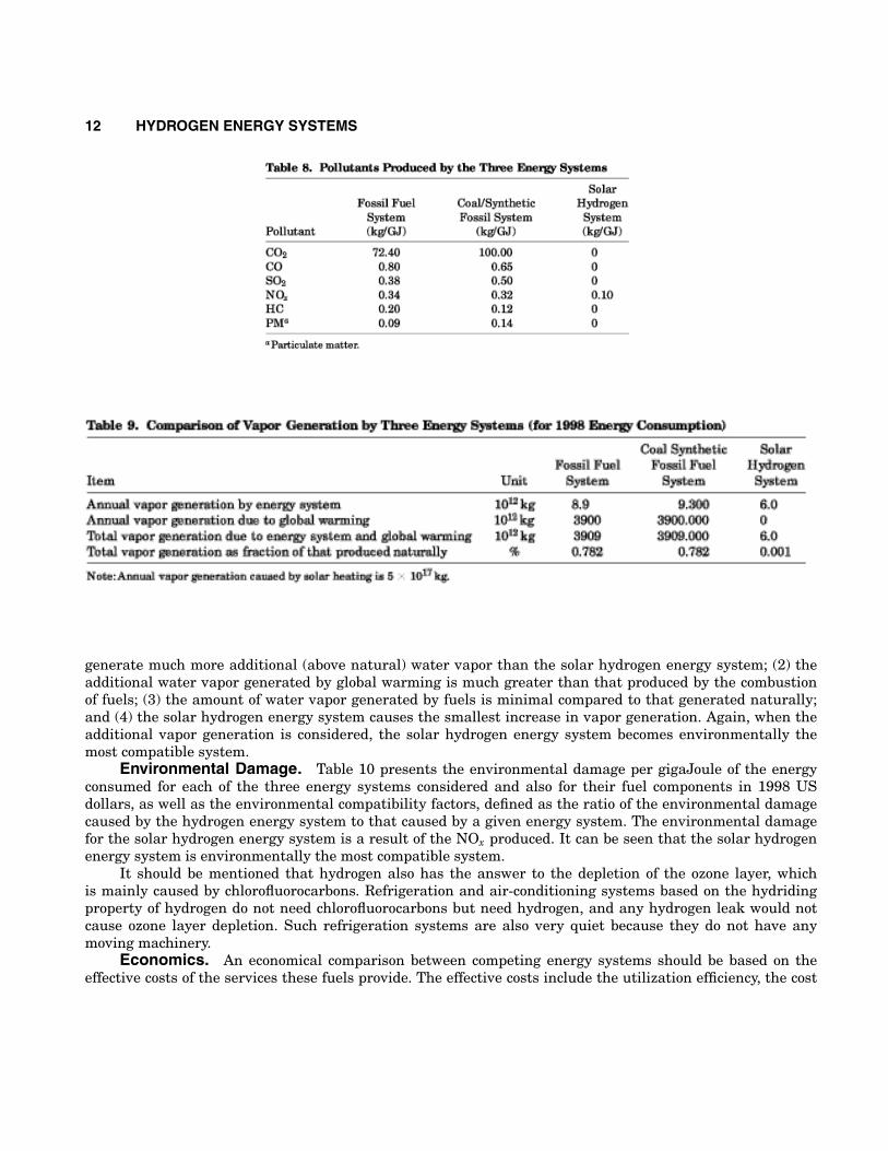
Solar Hydrogen Energy System. If solar energy, in its direct and/or indirect forms (e.g., hydro, wind,etc.), is used to manufacture hydrogen, then the resulting system is called the solar hydrogen energy system.In this system, both the primary and secondary energy sources are renewable and environmentally compatible,resulting in a clean and permanent energy system. Figure 5 presents a schematic of the solar hydrogen energysystem.
In this case, it is assumed that the conversion to hydrogen energy will take place, and one-third ofthe hydrogen needed will be produced from hydropower (and/or wind power) and two-thirds by direct andindirect (other than hydropower) from solar energy forms. The same percentage of energy demands sectors
HYDROGEN ENERGY SYSTEMS 11
Fig. 5. Solar-hydrogen energy system.
as the above systems will be assumed. It will further be assumed that one-half of the thermal energy will beachieved by flame combustion, one-quarter by steam generation with hydrogen/oxygen steam generators, andthe last quarter by catalytic combustion; electric power will be generated by fuel cells; one-half of the surfacetransportation will use gaseous hydrogen-burning internal combustion engines, and the other half will use fuelcells. In air transportation, both subsonic and supersonic, liquid hydrogen will be used.
Comparison of Energy Systems
These three energy systems will now be compared environmentally and economically.Pollution. Table 8 lists the pollutants for the three energy systems described earlier. It can be seen that
the coal/synthetic fossil system is the worst from the environmental point of view, whereas the solar hydrogenenergy system is the best. The solar hydrogen system will not produce any CO2, CO, SOx, hydrocarbons, orparticulates, except some NOx. However, the solar-hydrogen-produced NOx is much less than that producedby the other energy systems. This is due to the fact that in the solar hydrogen energy system only theflame combustion of hydrogen in air will generate NOx. The other utilization processes (such as direct steamgeneration, use of hydrogen in fuel cells, hydriding processes, etc.) will not produce any NOx.
Vapor Generation. There is a notion that the hydrogen energy system would produce more watervapor than the other energy systems because the fuel is pure hydrogen. When one considers the problem indetail, this is not so.
Only the flame combustion of fuels in air or in oxygen will produce water vapor. In the case of hydrogen,those other processes mentioned earlier will not produce any water vapor. Consequently, contrary to popularbelief, the solar hydrogen energy system will produce less water vapor than the other systems.
Global warming, which is caused by the utilization of fossil fuels, also causes an increase in watervapor generation. Assuming that Earth’s mean temperature has increased by 0.5◦C since the beginning of theIndustrial Revolution (26), this additional water vapor generation and that produced by the combustion of fuelshave been calculated. The results are presented in Table 9. It can be seen that (1) the two fossil fuel systems
12 HYDROGEN ENERGY SYSTEMS
generate much more additional (above natural) water vapor than the solar hydrogen energy system; (2) theadditional water vapor generated by global warming is much greater than that produced by the combustionof fuels; (3) the amount of water vapor generated by fuels is minimal compared to that generated naturally;and (4) the solar hydrogen energy system causes the smallest increase in vapor generation. Again, when theadditional vapor generation is considered, the solar hydrogen energy system becomes environmentally themost compatible system.
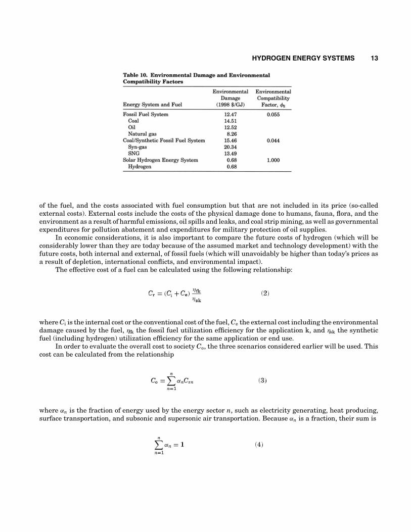
Environmental Damage. Table 10 presents the environmental damage per gigaJoule of the energyconsumed for each of the three energy systems considered and also for their fuel components in 1998 USdollars, as well as the environmental compatibility factors, defined as the ratio of the environmental damagecaused by the hydrogen energy system to that caused by a given energy system. The environmental damagefor the solar hydrogen energy system is a result of the NOx produced. It can be seen that the solar hydrogenenergy system is environmentally the most compatible system.
It should be mentioned that hydrogen also has the answer to the depletion of the ozone layer, whichis mainly caused by chlorofluorocarbons. Refrigeration and air-conditioning systems based on the hydridingproperty of hydrogen do not need chlorofluorocarbons but need hydrogen, and any hydrogen leak would notcause ozone layer depletion. Such refrigeration systems are also very quiet because they do not have anymoving machinery.
Economics. An economical comparison between competing energy systems should be based on theeffective costs of the services these fuels provide. The effective costs include the utilization efficiency, the cost
HYDROGEN ENERGY SYSTEMS 13
of the fuel, and the costs associated with fuel consumption but that are not included in its price (so-calledexternal costs). External costs include the costs of the physical damage done to humans, fauna, flora, and theenvironment as a result of harmful emissions, oil spills and leaks, and coal strip mining, as well as governmentalexpenditures for pollution abatement and expenditures for military protection of oil supplies.
In economic considerations, it is also important to compare the future costs of hydrogen (which will beconsiderably lower than they are today because of the assumed market and technology development) with thefuture costs, both internal and external, of fossil fuels (which will unavoidably be higher than today’s prices asa result of depletion, international conflicts, and environmental impact).
The effective cost of a fuel can be calculated using the following relationship:
where Ci is the internal cost or the conventional cost of the fuel, Ce the external cost including the environmentaldamage caused by the fuel, ηfk the fossil fuel utilization efficiency for the application k, and ηsk the syntheticfuel (including hydrogen) utilization efficiency for the same application or end use.
In order to evaluate the overall cost to society Co, the three scenarios considered earlier will be used. Thiscost can be calculated from the relationship
where αn is the fraction of energy used by the energy sector n, such as electricity generating, heat producing,surface transportation, and subsonic and supersonic air transportation. Because αn is a fraction, their sum is
14 HYDROGEN ENERGY SYSTEMS
Substituting Eq. (2) into Eq. (3), one obtains
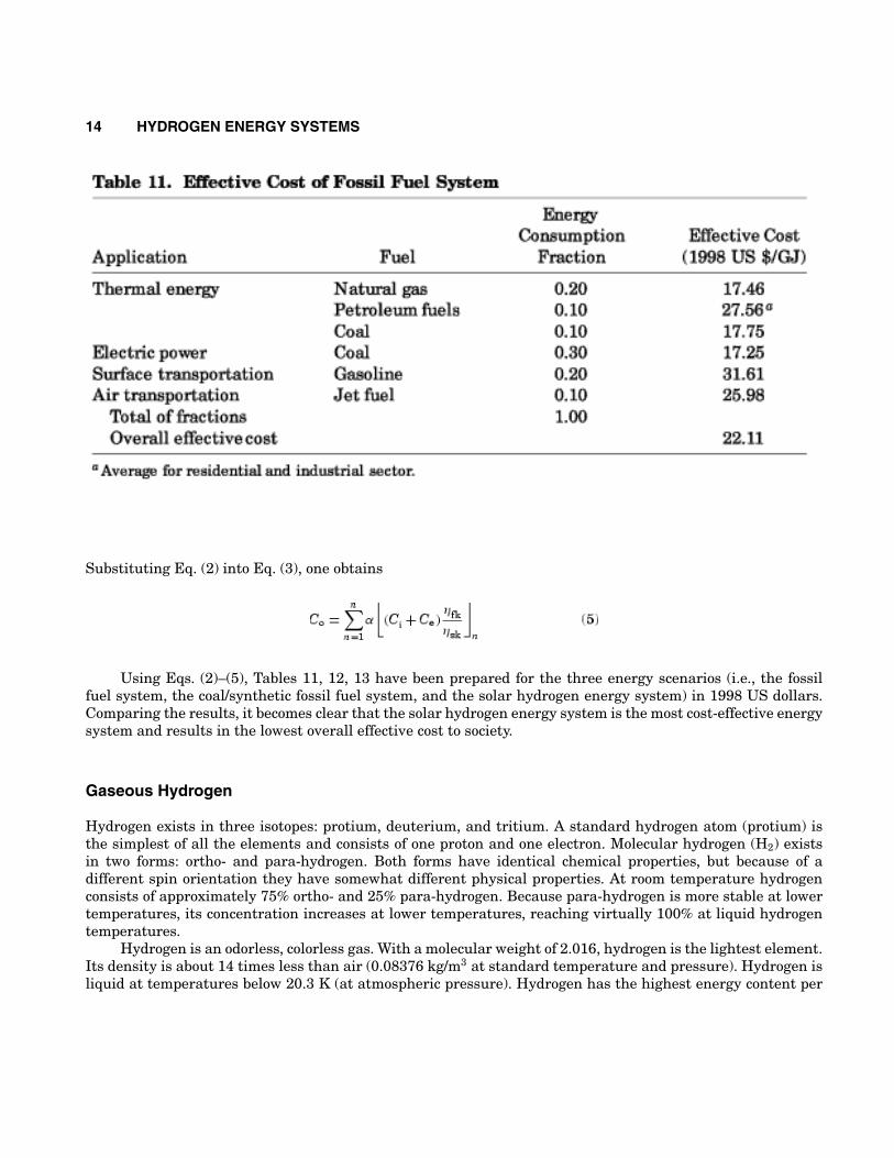
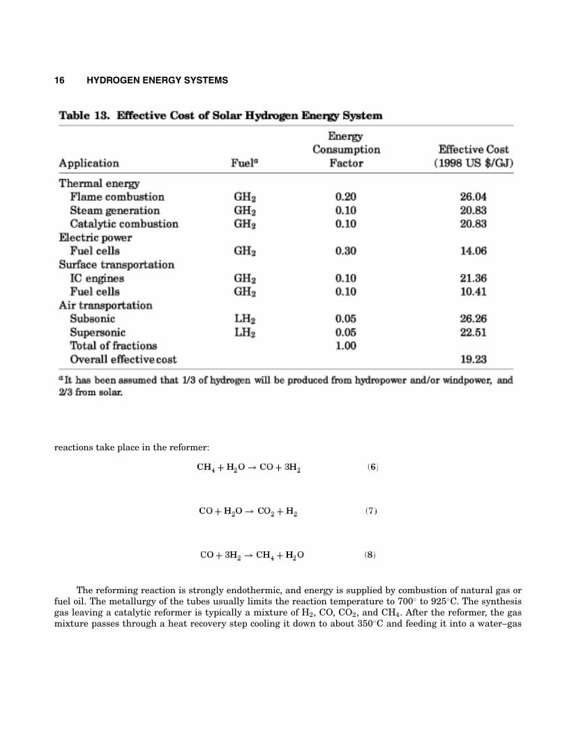
Using Eqs. (2)–(5), Tables 11, 12, 13 have been prepared for the three energy scenarios (i.e., the fossilfuel system, the coal/synthetic fossil fuel system, and the solar hydrogen energy system) in 1998 US dollars.Comparing the results, it becomes clear that the solar hydrogen energy system is the most cost-effective energysystem and results in the lowest overall effective cost to society.
Gaseous Hydrogen
Hydrogen exists in three isotopes: protium, deuterium, and tritium. A standard hydrogen atom (protium) isthe simplest of all the elements and consists of one proton and one electron. Molecular hydrogen (H2) existsin two forms: ortho- and para-hydrogen. Both forms have identical chemical properties, but because of adifferent spin orientation they have somewhat different physical properties. At room temperature hydrogenconsists of approximately 75% ortho- and 25% para-hydrogen. Because para-hydrogen is more stable at lowertemperatures, its concentration increases at lower temperatures, reaching virtually 100% at liquid hydrogentemperatures.
Hydrogen is an odorless, colorless gas. With a molecular weight of 2.016, hydrogen is the lightest element.Its density is about 14 times less than air (0.08376 kg/m3 at standard temperature and pressure). Hydrogen isliquid at temperatures below 20.3 K (at atmospheric pressure). Hydrogen has the highest energy content per

HYDROGEN ENERGY SYSTEMS 15
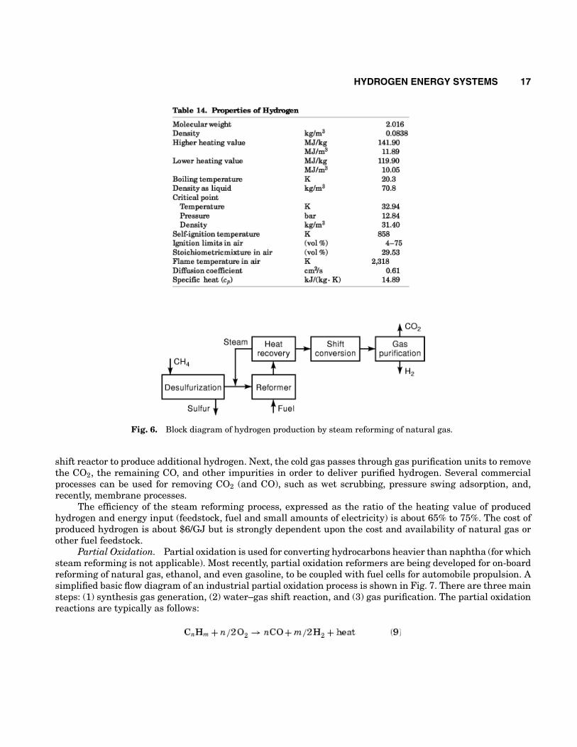
unit mass of all fuels—higher heating value is 141.9 MJ/kg, almost three times higher than gasoline. Someimportant properties of hydrogen are compiled in Table 14.
Hydrogen Production. Hydrogen is the most plentiful element in the universe, making up aboutthree-quarters of all matter. All the stars and many of the planets essentially consist of hydrogen. However, onEarth free hydrogen is scarce. The atmosphere contains trace amounts of it (0.07%), and it is usually found insmall amounts mixed with natural gas in crustal reservoirs. A few wells, however, have been found to containlarge amounts of hydrogen, such as some wells in Kansas that contain 40% hydrogen, 60% nitrogen and traceamounts of hydrocarbons (27). The Earth’s surface contains about 0.14% hydrogen (the tenth most abundantelement), most of which resides in a chemical combination with oxygen as water.
Hydrogen, therefore, must be produced. Logical sources of hydrogen are hydrocarbon (fossil) fuels (CxHy)and water (H2O). Presently, hydrogen is mostly being produced from fossil fuels (natural gas, oil, and coal).
Except for the space program, hydrogen is not being used directly as a fuel or energy carrier. It is beingused in refineries to upgrade crude oil (hydrotreating and hydrocracking), in the chemical industry to synthesizevarious chemical compounds (such as ammonia and methanol), and in metallurgical processes (as a reductionor protection gas). The total annual hydrogen production worldwide in 1996 was about 40 million tons (5.6 EJ)(28). Less than 10% of this was supplied by industrial gas companies; the rest is produced at consumer-ownedand -operated plants (so-called captive production), such as refineries, and ammonia and methanol producers.Production of hydrogen as an energy carrier would require an increase in production rates by several orders ofmagnitude.
Hydrogen Production from Fossil Fuels.Steam Reforming of Natural Gas. Steam reforming of hydrocarbons (mainly natural gas) has been the
most efficient, economical, and widely used process for hydrogen production. A simplified basic flow diagramof a conventional steam reforming process is shown in Fig. 6 (29). The process basically consists of three mainsteps: (1) synthesis gas generation, (2) water–gas shift, and (3) gas purification. The feedstock (natural gas) ismixed with process steam and reacted over a nickel-based catalyst contained inside a system of alloyed steeltubes. To protect the catalyst, natural gas must be desulfurized before being fed to the reformer. The following
16 HYDROGEN ENERGY SYSTEMS
reactions take place in the reformer:
The reforming reaction is strongly endothermic, and energy is supplied by combustion of natural gas orfuel oil. The metallurgy of the tubes usually limits the reaction temperature to 700◦ to 925◦C. The synthesisgas leaving a catalytic reformer is typically a mixture of H2, CO, CO2, and CH4. After the reformer, the gasmixture passes through a heat recovery step cooling it down to about 350◦C and feeding it into a water–gas
HYDROGEN ENERGY SYSTEMS 17
Fig. 6. Block diagram of hydrogen production by steam reforming of natural gas.
shift reactor to produce additional hydrogen. Next, the cold gas passes through gas purification units to removethe CO2, the remaining CO, and other impurities in order to deliver purified hydrogen. Several commercialprocesses can be used for removing CO2 (and CO), such as wet scrubbing, pressure swing adsorption, and,recently, membrane processes.
The efficiency of the steam reforming process, expressed as the ratio of the heating value of producedhydrogen and energy input (feedstock, fuel and small amounts of electricity) is about 65% to 75%. The cost ofproduced hydrogen is about $6/GJ but is strongly dependent upon the cost and availability of natural gas orother fuel feedstock.
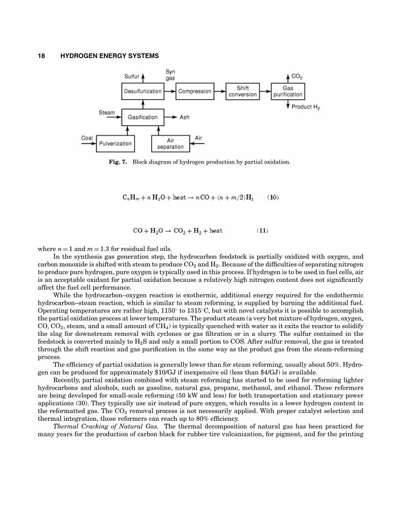
Partial Oxidation. Partial oxidation is used for converting hydrocarbons heavier than naphtha (for whichsteam reforming is not applicable). Most recently, partial oxidation reformers are being developed for on-boardreforming of natural gas, ethanol, and even gasoline, to be coupled with fuel cells for automobile propulsion. Asimplified basic flow diagram of an industrial partial oxidation process is shown in Fig. 7. There are three mainsteps: (1) synthesis gas generation, (2) water–gas shift reaction, and (3) gas purification. The partial oxidationreactions are typically as follows:
18 HYDROGEN ENERGY SYSTEMS
Fig. 7. Block diagram of hydrogen production by partial oxidation.
where n = 1 and m = 1.3 for residual fuel oils.In the synthesis gas generation step, the hydrocarbon feedstock is partially oxidized with oxygen, and
carbon monoxide is shifted with steam to produce CO2 and H2. Because of the difficulties of separating nitrogento produce pure hydrogen, pure oxygen is typically used in this process. If hydrogen is to be used in fuel cells, airis an acceptable oxidant for partial oxidation because a relatively high nitrogen content does not significantlyaffect the fuel cell performance.
While the hydrocarbon–oxygen reaction is exothermic, additional energy required for the endothermichydrocarbon–steam reaction, which is similar to steam reforming, is supplied by burning the additional fuel.Operating temperatures are rather high, 1150◦ to 1315◦C, but with novel catalysts it is possible to accomplishthe partial oxidation process at lower temperatures. The product steam (a very hot mixture of hydrogen, oxygen,CO, CO2, steam, and a small amount of CH4) is typically quenched with water as it exits the reactor to solidifythe slag for downstream removal with cyclones or gas filtration or in a slurry. The sulfur contained in thefeedstock is converted mainly to H2S and only a small portion to COS. After sulfur removal, the gas is treatedthrough the shift reaction and gas purification in the same way as the product gas from the steam-reformingprocess.
The efficiency of partial oxidation is generally lower than for steam reforming, usually about 50%. Hydro-gen can be produced for approximately $10/GJ if inexpensive oil (less than $4/GJ) is available.
Recently, partial oxidation combined with steam reforming has started to be used for reforming lighterhydrocarbons and alcohols, such as gasoline, natural gas, propane, methanol, and ethanol. These reformersare being developed for small-scale reforming (50 kW and less) for both transportation and stationary powerapplications (30). They typically use air instead of pure oxygen, which results in a lower hydrogen content inthe reformatted gas. The CO2 removal process is not necessarily applied. With proper catalyst selection andthermal integration, those reformers can reach up to 80% efficiency.
Thermal Cracking of Natural Gas. The thermal decomposition of natural gas has been practiced formany years for the production of carbon black for rubber tire vulcanization, for pigment, and for the printing
HYDROGEN ENERGY SYSTEMS 19
Fig. 8. Block diagram of hydrogen production by coal gasification process.
industry. A methane–air flame is used to heat up firebrick to temperatures in the order of 1400◦C. The air isthen turned off, and the methane alone decomposes on the hot firebrick until the temperature drops to about800◦C. The micron-size carbon particles are collected in the effluent gas stream in bag filters. The processis typically practiced batchwise in tandem furnaces: while one furnace is producing carbon black, the otheris being heated up. Attempts have also been made to thermally crack natural gas in a continuous fixed bedreactor (31). With appropriate catalysts, it is possible to increase the rate of decomposition and accomplish anefficient continuous process (32). Another approach is to use high-temperature plasma for thermal cracking ofnatural gas or even heavier hydrocarbons (33).
Because of a valuable by-product (carbon black), the economics of this process for hydrogen productionlook favorable. It should be noted that this is the only process of hydrogen production from hydrocarbons thatdoes not produce CO2 (unless carbon black is later used as a fuel).
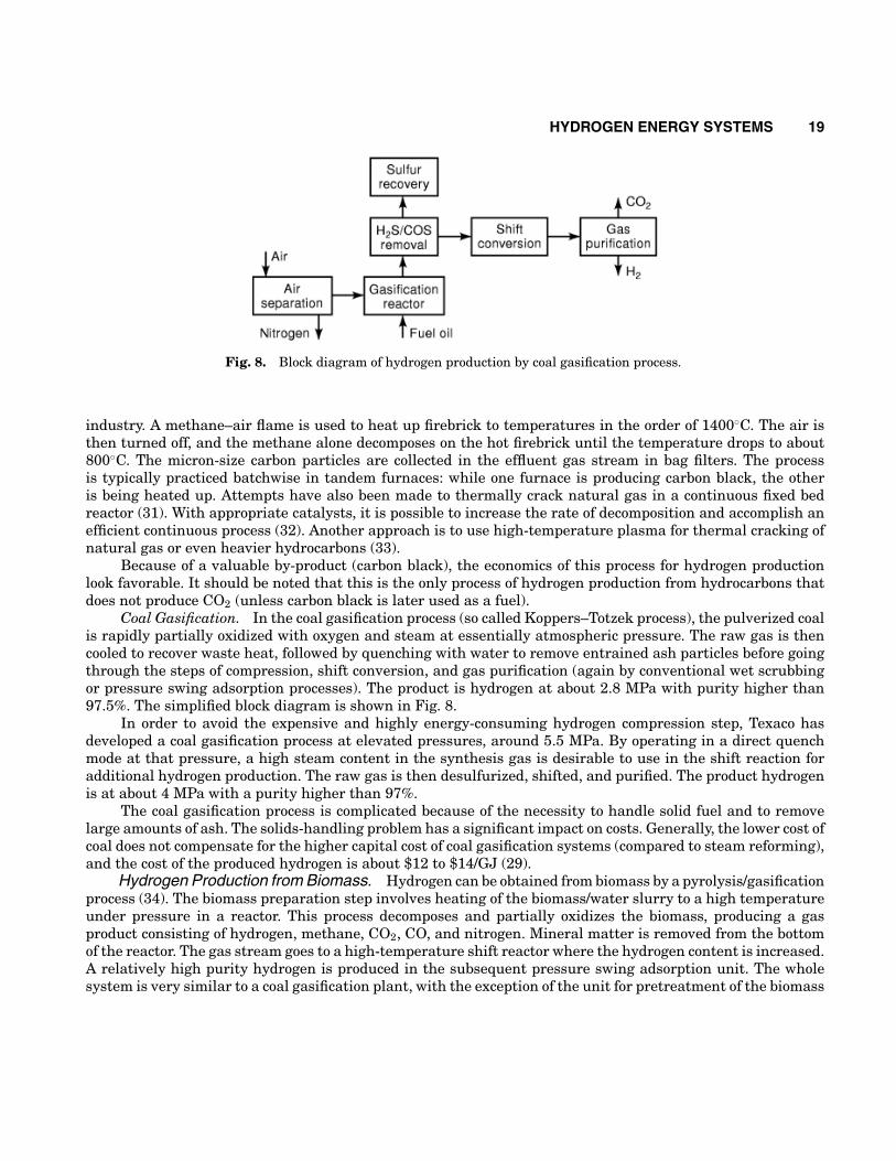
Coal Gasification. In the coal gasification process (so called Koppers–Totzek process), the pulverized coalis rapidly partially oxidized with oxygen and steam at essentially atmospheric pressure. The raw gas is thencooled to recover waste heat, followed by quenching with water to remove entrained ash particles before goingthrough the steps of compression, shift conversion, and gas purification (again by conventional wet scrubbingor pressure swing adsorption processes). The product is hydrogen at about 2.8 MPa with purity higher than97.5%. The simplified block diagram is shown in Fig. 8.
In order to avoid the expensive and highly energy-consuming hydrogen compression step, Texaco hasdeveloped a coal gasification process at elevated pressures, around 5.5 MPa. By operating in a direct quenchmode at that pressure, a high steam content in the synthesis gas is desirable to use in the shift reaction foradditional hydrogen production. The raw gas is then desulfurized, shifted, and purified. The product hydrogenis at about 4 MPa with a purity higher than 97%.
The coal gasification process is complicated because of the necessity to handle solid fuel and to removelarge amounts of ash. The solids-handling problem has a significant impact on costs. Generally, the lower cost ofcoal does not compensate for the higher capital cost of coal gasification systems (compared to steam reforming),and the cost of the produced hydrogen is about $12 to $14/GJ (29).
Hydrogen Production from Biomass. Hydrogen can be obtained from biomass by a pyrolysis/gasificationprocess (34). The biomass preparation step involves heating of the biomass/water slurry to a high temperatureunder pressure in a reactor. This process decomposes and partially oxidizes the biomass, producing a gasproduct consisting of hydrogen, methane, CO2, CO, and nitrogen. Mineral matter is removed from the bottomof the reactor. The gas stream goes to a high-temperature shift reactor where the hydrogen content is increased.A relatively high purity hydrogen is produced in the subsequent pressure swing adsorption unit. The wholesystem is very similar to a coal gasification plant, with the exception of the unit for pretreatment of the biomass
20 HYDROGEN ENERGY SYSTEMS
and the design of the reactor. Because of the lower calorific value per unit mass of biomass as compared to coal,the processing facility is larger than that of comparably sized coal gasification plants.
Hydrogen Production from Water. The most logical source for large-scale hydrogen production is water,which is abundant on Earth. Different methods of hydrogen production from water have been or are beingdeveloped. They include
• electrolysis,• direct thermal decomposition or thermolysis,• thermochemical processes, and• photolysis.
Electrolysis. Electrolysis appears to be the only method developed to date that can be used for large-scale hydrogen production in a post-fossil fuel era. Production of hydrogen by water electrolysis is a 50-year oldtechnology, as based on a fundamentally simple process, is very efficient, and does not involve moving parts.
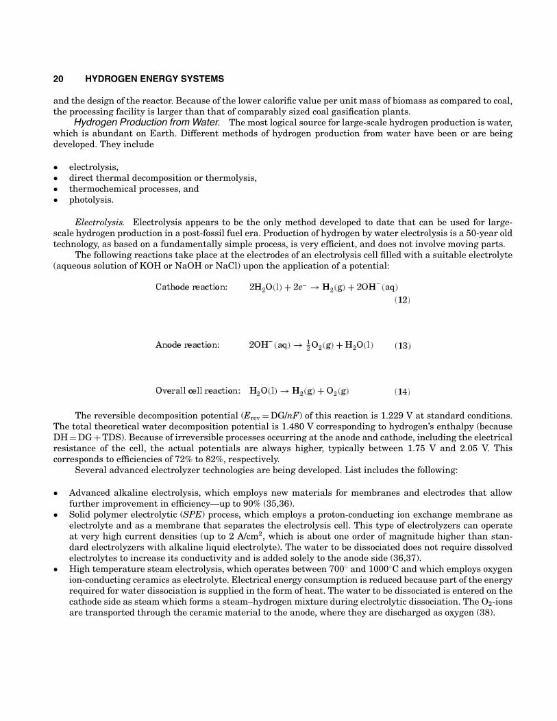
The following reactions take place at the electrodes of an electrolysis cell filled with a suitable electrolyte(aqueous solution of KOH or NaOH or NaCl) upon the application of a potential:
The reversible decomposition potential (Erev = DG/nF) of this reaction is 1.229 V at standard conditions.The total theoretical water decomposition potential is 1.480 V corresponding to hydrogen’s enthalpy (becauseDH = DG + TDS). Because of irreversible processes occurring at the anode and cathode, including the electricalresistance of the cell, the actual potentials are always higher, typically between 1.75 V and 2.05 V. Thiscorresponds to efficiencies of 72% to 82%, respectively.
Several advanced electrolyzer technologies are being developed. List includes the following:
• Advanced alkaline electrolysis, which employs new materials for membranes and electrodes that allowfurther improvement in efficiency—up to 90% (35,36).
• Solid polymer electrolytic (SPE) process, which employs a proton-conducting ion exchange membrane aselectrolyte and as a membrane that separates the electrolysis cell. This type of electrolyzers can operateat very high current densities (up to 2 A/cm2, which is about one order of magnitude higher than stan-dard electrolyzers with alkaline liquid electrolyte). The water to be dissociated does not require dissolvedelectrolytes to increase its conductivity and is added solely to the anode side (36,37).
• High temperature steam electrolysis, which operates between 700◦ and 1000◦C and which employs oxygenion-conducting ceramics as electrolyte. Electrical energy consumption is reduced because part of the energyrequired for water dissociation is supplied in the form of heat. The water to be dissociated is entered on thecathode side as steam which forms a steam–hydrogen mixture during electrolytic dissociation. The O2-ionsare transported through the ceramic material to the anode, where they are discharged as oxygen (38).
HYDROGEN ENERGY SYSTEMS 21
An electrolysis plant can operate over a wide range of capacity factors and is convenient for a wide rangeof operating capacities, which makes this process interesting for coupling with renewable energy sources,particularly with photovoltaics. Photovoltaics generate low voltage–direct current, which is exactly what isrequired for the electrolysis process.
Performance of photovoltaic–electrolyzer systems has been studied extensively both in theory and inpractice (39,40,41,42). Several experimental PV-electrolysis plants are currently operating all over the world,such as
• Solar-Wasserstoff-Bayern pilot plant in Neunburg vorm Wald in Germany (43),• HYSOLAR project in Saudi Arabia (44),• Schatz Energy Center, Humboldt State University, Arcata, California (45),• Helsinki University of Technology, Helsinki, Finland (46),• INTA Energy Laboratory, Huelva, Spain (47).
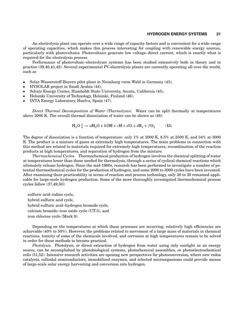
Direct Thermal Decomposition of Water (Thermolysis). Water can be split thermally at temperaturesabove 2000 K. The overall thermal dissociation of water can be shown as (48):
The degree of dissociation is a function of temperature: only 1% at 2000 K, 8.5% at 2500 K, and 34% at 3000K. The product is a mixture of gases at extremely high temperatures. The main problems in connection withthis method are related to materials required for extremely high temperatures, recombination of the reactionproducts at high temperatures, and separation of hydrogen from the mixture.
Thermochemical Cycles. Thermochemical production of hydrogen involves the chemical splitting of waterat temperatures lower than those needed for thermolysis, through a series of cyclical chemical reactions whichultimately release hydrogen. Since the mid-1960s, research has been performed to investigate a number of po-tential thermochemical cycles for the production of hydrogen, and some 2000 to 3000 cycles have been invented.After examining their practicability in terms of reaction and process technology, only 20 to 30 remained appli-cable for large-scale hydrogen production. Some of the more thoroughly investigated thermochemical processcycles follow (37,49,50):
sulfuric acid–iodine cycle,hybrid sulfuric acid cycle,hybrid sulfuric acid–hydrogen bromide cycle,calcium bromide–iron oxide cycle (UT-3), andiron chlorine cycle (Mark 9).
Depending on the temperatures at which these processes are occurring, relatively high efficiencies areachievable (40% to 50%). However, the problems related to movement of a large mass of materials in chemicalreactions, toxicity of some of the chemicals involved, and corrosion at high temperatures remain to be solvedin order for these methods to become practical.
Photolysis. Photolysis, or direct extraction of hydrogen from water using only sunlight as an energysource, can be accomplished by photobiological systems, photochemical assemblies, or photoelectrochemicalcells (51,52). Intensive research activities are opening new perspectives for photoconversion, where new redoxcatalysts, colloidal semiconductors, immobilized enzymes, and selected microorganisms could provide meansof large-scale solar energy harvesting and conversion into hydrogen.
22 HYDROGEN ENERGY SYSTEMS
Gaseous Hydrogen Storage and Distribution. Hydrogen as an energy carrier must be stored toovercome daily and seasonal discrepancies between energy source availability and demand. Also, to over-come geographical discrepancies between hydrogen production sites and hydrogen users, hydrogen has to betransported.
Gaseous Hydrogen Storage. Hydrogen can be stored either as a pressurized gas or as a liquid. It alsocan be stored in chemical or physical combinations with other materials, such as metal hydrides, chemicalhydrides, glass microspheres, and cryo-absorbers. Depending on storage size and application, several types ofhydrogen storage systems may be differentiated:
(1) Stationary Large Storage Systems These are typically storage devices at the production site or at the startor end of pipelines and other transportation pathways.
(2) Stationary Small Storage Systems These can be found at the distribution or final user level, for example, astorage system to meet the demand of an industrial plant.
(3) Mobile Storage Systems for Transport and Distribution These include both large-capacity devices, suchas a liquid hydrogen tanker–bulk carrier, and small systems, such as a gaseous or liquid hydrogen trucktrailer.
(4) Vehicle Tanks These store hydrogen used as fuel for road vehicles.
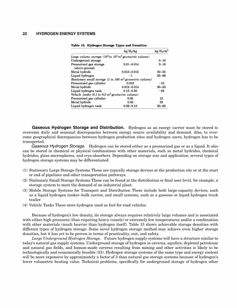
Because of hydrogen’s low density, its storage always requires relatively large volumes and is associatedwith either high pressures (thus requiring heavy vessels) or extremely low temperatures and/or a combinationwith other materials (much heavier than hydrogen itself). Table 15 shows achievable storage densities withdifferent types of hydrogen storage. Some novel hydrogen storage method may achieve even higher storagedensities, but it has yet to be proven in terms of practicality, cost, and safety.
Large Underground Hydrogen Storage. Future hydrogen supply systems will have a structure similar totoday’s natural gas supply systems. Underground storage of hydrogen in caverns, aquifers, depleted petroleumand natural gas fields, and human-made caverns resulting from mining and other activities is likely to betechnologically and economically feasible (53). Hydrogen storage systems of the same type and energy contentwill be more expensive by approximately a factor of 3 than natural gas storage systems because of hydrogen’slower volumetric heating value. Technical problems, specifically for underground storage of hydrogen other
HYDROGEN ENERGY SYSTEMS 23
than expected losses of the working gas in the amount of 1% to 3% per year are not anticipated. The city ofKiel’s public utility has been storing town gas with a hydrogen content of 60% to 65% in a gas cavern with ageometric volume of about 32,000 m3 and a pressure of 80 to 160 bar at a depth of 1330 m since 1971 (54).Gaz de France, the French National Gas Company, has stored hydrogen-rich refinery by-product gases in anaquifer structure near Beynes, France. Imperial Chemical Industries of Great Britain stores its hydrogen inthe salt mine caverns near Teeside in the United Kingdom (55).
Above-Ground Pressurized Gas Storage Systems. Pressurized gas storage systems are used today innatural gas businesses in various sizes and pressure ranges from standard pressure cylinders (0.05 m3, 200bar) to stationary high-pressure containers (over 200 bar) or low-pressure spherical containers (>30,000 m3,12 bar to 16 bar). This application range will be similar for hydrogen storage.
Vehicular Pressurized Hydrogen Tanks. Development of ultralight but strong new composite materialshas enabled storage of hydrogen in automobiles. Pressure vessels that allow hydrogen storage at pressures>200 bar have been developed and used in automobiles (such as Daimler-Benz NECAR II). Storage density ofhigher than 0.05 kg H2/kg of total weight is easily achievable (56).
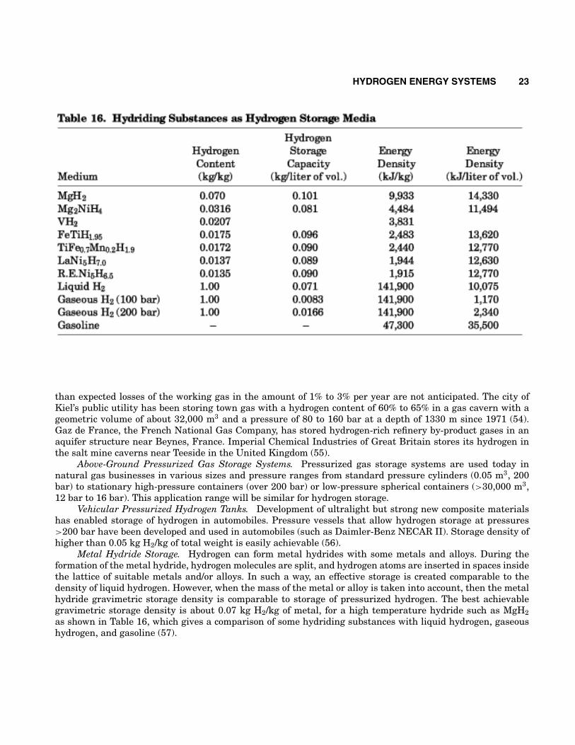
Metal Hydride Storage. Hydrogen can form metal hydrides with some metals and alloys. During theformation of the metal hydride, hydrogen molecules are split, and hydrogen atoms are inserted in spaces insidethe lattice of suitable metals and/or alloys. In such a way, an effective storage is created comparable to thedensity of liquid hydrogen. However, when the mass of the metal or alloy is taken into account, then the metalhydride gravimetric storage density is comparable to storage of pressurized hydrogen. The best achievablegravimetric storage density is about 0.07 kg H2/kg of metal, for a high temperature hydride such as MgH2as shown in Table 16, which gives a comparison of some hydriding substances with liquid hydrogen, gaseoushydrogen, and gasoline (57).
24 HYDROGEN ENERGY SYSTEMS
During the storage process (charging or absorption), heat is released. This heat must be removed in orderto achieve the continuity of the reaction. During the hydrogen release process (discharging or desorption), heatmust be supplied to the storage tank.
An advantage of storing hydrogen in hydriding substances is the safety aspect. A serious damage to ahydride tank (such as the one that could be caused by a collision) would not pose a fire hazard because hydrogenwould remain in the metal structure.
Novel Hydrogen Storage Methods. Hydrogen can be physically adsorbed on activated carbon and be“packed” on the surface and inside the carbon structure more densely than if it has been just compressed.Amounts of up to 48 g H2/kg of carbon have been reported at 6.0 MPa and 87 K (58). The adsorption capacity isa function of pressure and temperature; therefore, at higher pressures and/or lower temperatures even largeramounts of hydrogen can be adsorbed. For any practical use, relatively low temperatures are needed (<100K). Because adsorption is a surface process, the adsorption capacity of hydrogen on activated carbon is largelythe result of the high surface area of the activated carbon, although some other carbon properties affect thecapability of activated carbon to adsorb hydrogen.
Researchers from Northeastern University in Boston, MA, have recently announced that they have de-veloped a carbon storage material that can store as high as 75% of hydrogen by weight (59). This material,apparently some kind of carbon nanotubes or carbon whiskers, is currently being researched in several labora-tories. The best results achieved with carbon nanotubes to date confirmed by the National Renewable EnergyLaboratory is hydrogen storage density corresponding to about 10% of the nanotube weight (60).
Hydrogen can be stored in glass microspheres of approximately 50 mm diameter. The microspheres canbe filled with hydrogen by heating them to increase the glass permeability to hydrogen. At room temperature,a pressure of approximately 25 MPa is achieved, resulting in a storage density of 14% mass fraction and 10 kgH2/m3 (61). At 62 MPa, a bed of glass microspheres can store 20 kg H2/m3. The release of hydrogen occurs byreheating the spheres to again increase the permeability.
Researchers at the University of Hawaii are investigating hydrogen storage via polyhydride complexes.Complexes that catalyze the reversible hydrogenation of unsaturated hydrocarbons have been found. Thiscatalytic reaction could be the basis for a low-temperature hydrogen storage system with an available hydrogendensity greater than 7% (62).
Hydrogen Transport and Distribution.Interregional Hydrogen Transport. In the hydrogen energy system, it is envisaged that, from the
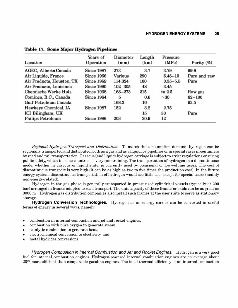
production plants and/or storage, hydrogen will be transmitted to consumers by means of undergroundpipelines (gaseous hydrogen) and/or supertankers (liquid hydrogen). Presently, hydrogen transportationthrough pipelines is used either in links between nearby production and utilization sites (up to 10 km) orin more extensive networks (roughly 200 km). Table 17 lists the principal existing hydrogen pipelines (63).Future developments will certainly entail greater flow rates and distances. It would be possible to use theexisting natural gas pipelines with some modifications. For hydrogen pipelines, it is necessary to use steelsless prone to embrittlement by hydrogen under pressure [particularly for very pure hydrogen (>99.5% purity)].Reciprocating compressors used for natural gas can be used for hydrogen without major design modifications.However, special attention must be given to sealing (to avoid hydrogen leaks) and to materials selection for theparts subject to fatigue stress. Use of centrifugal compressors for hydrogen creates more problems because ofhydrogen’s exceptional lightness.
As a rule, hydrogen transmission through pipelines requires larger diameter piping and more compressionpower than natural gas for the same energy throughput. However, because of lower pressure losses in the caseof hydrogen, the recompression stations would need to be spaced twice as far apart. In economic terms, mostof the studies found that the cost of large-scale transmission of hydrogen is about 1.5 to 1.8 times that ofnatural gas transmission. However, transportation of hydrogen over distances greater than 1000 km is moreeconomical than transmission of electricity (64).
HYDROGEN ENERGY SYSTEMS 25
Regional Hydrogen Transport and Distribution. To match the consumption demand, hydrogen can beregionally transported and distributed, both as a gas and as a liquid, by pipelines or in special cases in containersby road and rail transportation. Gaseous (and liquid) hydrogen carriage is subject to strict regulations ensuringpublic safety, which in some countries is very constraining. The transportation of hydrogen in a discontinuousmode, whether in gaseous or liquid state, is currently used by occasional or low-volume users. The cost ofdiscontinuous transport is very high (it can be as high as two to five times the production cost). In the futureenergy system, discontinuous transportation of hydrogen would see little use, except for special users (mainlynon-energy-related).
Hydrogen in the gas phase is generally transported in pressurized cylindrical vessels (typically at 200bar) arranged in frames adapted to road transport. The unit capacity of these frames or skids can be as great as3000 m3. Hydrogen gas distribution companies also install such frames at the user’s site to serve as stationarystorage.
Hydrogen Conversion Technologies. Hydrogen as an energy carrier can be converted in usefulforms of energy in several ways, namely:
• combustion in internal combustion and jet and rocket engines,• combustion with pure oxygen to generate steam,• catalytic combustion to generate heat,• electrochemical conversion to electricity, and• metal hydrides conversions.
Hydrogen Combustion in Internal Combustion and Jet and Rocket Engines. Hydrogen is a very goodfuel for internal combustion engines. Hydrogen-powered internal combustion engines are on average about20% more efficient than comparable gasoline engines. The ideal thermal efficiency of an internal combustion
26 HYDROGEN ENERGY SYSTEMS
engine is
wherer = compression ratio andk = ratio of specific heats (Cp/Cv).
Equation (16) shows that the thermal efficiency can be improved by increasing either the compressionratio or the specific heat ratio. In hydrogen engines, both ratios are higher than in a comparable gasoline enginebecause of hydrogen’s lower self-ignition temperature and ability to burn in lean mixtures. However, the useof hydrogen in internal combustion engines results in the loss of power because of the lower energy contentin a stoichiometric mixture in the engine’s cylinder. A stoichiometric mixture of gasoline and air and gaseoushydrogen and air premixed externally occupy ∼2% and 30% of the cylinder volume, respectively. Under theseconditions, the energy of the hydrogen mixture is only 85% of the gasoline mixture, thus resulting in about 15%reduction in power. Therefore, the same engine running on hydrogen will have ∼15% less power than whenoperated with gasoline. The power output of a hydrogen engine can be improved by using more advanced fuelinjection techniques or liquid hydrogen. For example, if liquid hydrogen is premixed with air, the amount ofhydrogen that can be introduced in the combustion cylinder can be increased by approximately one-third (65).
One of the most important advantages of hydrogen as a fuel for internal combustion engines is thathydrogen engines emit by far fewer pollutants than comparable gasoline engines. Basically, the only productsof hydrogen combustion in air are water vapor and small amounts of nitrogen oxides. Hydrogen has a wideflammability range in air (5% to 75% vol.), therefore, high excess air can be utilized more effectively. Theformation of nitrogen oxides in hydrogen/air combustion can be minimized with excess air. NOx emissionscan also be lowered by cooling the combustion environment using techniques such as water injection, exhaustgas recirculation, or using liquid hydrogen. The emissions of NOx in hydrogen engines are typically oneorder of magnitude smaller than emissions from comparable gasoline engines. Small amounts of unburnedhydrocarbons, CO2, and CO have been detected in hydrogen engines due to lubrication oil (65).
The low-ignition energy and fast-flame propagation of hydrogen have led to problems of preignition andbackfire. These problems have been overcome by adding hydrogen to the air mixture at the point whereand when the conditions for preignition are less likely, such as delivering the fuel and air separately to thecombustion chamber and/or injecting hydrogen under pressure into the combustion chamber before the pistonis at the top dead center and after the intake air valve has been closed. Water injection and exhaust gasrecirculation techniques are also used in hydrogen engines to help control premature ignition. Note that mostof the research on hydrogen combustion in internal combustion engines has been conducted with modificationsof existing engines designed to burn gasoline. Redesign of the combustion chamber and coolant systems toaccommodate hydrogen’s unique combustion properties could be the most effective method of solving theproblems of preignition and knocking (65).
Hydrogen use in turbines and jet engines is similar to the use of conventional jet fuel. The use of hydrogenavoids the problems of sediments and corrosion on turbine blades which prolongs life and reduces maintenance.Gas inlet temperatures can be pushed beyond normal gas turbine temperatures of 800◦C, thus increasing theoverall efficiency. The only pollutants from the use of hydrogen in turbines and jet engines are nitrogen oxides.
Steam Generation by Hydrogen/Oxygen Combustion. Hydrogen combusted with pure oxygen resultsin pure steam; that is,
HYDROGEN ENERGY SYSTEMS 27
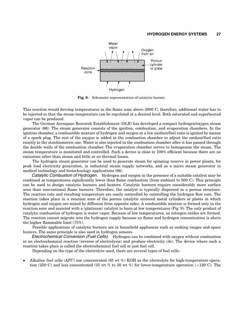
Fig. 9. Schematic representation of catalytic burner.
This reaction would develop temperatures in the flame zone above 3000◦C; therefore, additional water has tobe injected so that the steam temperature can be regulated at a desired level. Both saturated and superheatedvapor can be produced.
The German Aerospace Research Establishment (DLR) has developed a compact hydrogen/oxygen steamgenerator (66). The steam generator consists of the ignition, combustion, and evaporation chambers. In theignition chamber, a combustible mixture of hydrogen and oxygen at a low oxidant/fuel ratio is ignited by meansof a spark plug. The rest of the oxygen is added in the combustion chamber to adjust the oxidant/fuel ratioexactly to the stoichiometric one. Water is also injected in the combustion chamber after it has passed throughthe double walls of the combustion chamber. The evaporation chamber serves to homogenize the steam. Thesteam temperature is monitored and controlled. Such a device is close to 100% efficient because there are noemissions other than steam and little or no thermal losses.
The hydrogen steam generator can be used to generate steam for spinning reserve in power plants, forpeak load electricity generation, in industrial steam supply networks, and as a micro steam generator inmedical technology and biotechnology applications (66).
Catalytic Combustion of Hydrogen. Hydrogen and oxygen in the presence of a suitable catalyst may becombined at temperatures significantly lower than flame combustion (from ambient to 500◦C). This principlecan be used to design catalytic burners and heaters. Catalytic burners require considerably more surfacearea than conventional flame burners. Therefore, the catalyst is typically dispersed in a porous structure.The reaction rate and resulting temperature are easily controlled by controlling the hydrogen flow rate. Thereaction takes place in a reaction zone of the porous catalytic sintered metal cylinders or plates in whichhydrogen and oxygen are mixed by diffusion from opposite sides. A combustible mixture is formed only in thereaction zone and assisted with a (platinum) catalyst to burn at low temperatures (Fig. 9). The only product ofcatalytic combustion of hydrogen is water vapor. Because of low temperatures, no nitrogen oxides are formed.The reaction cannot migrate into the hydrogen supply because no flame and hydrogen concentration is abovethe higher flammable limit (75%).
Possible applications of catalytic burners are in household appliances such as cooking ranges and spaceheaters. The same principle is also used in hydrogen sensors.
Electrochemical Conversion (Fuel Cells). Hydrogen can be combined with oxygen without combustionin an electrochemical reaction (reverse of electrolysis) and produce electricity (dc). The device where such areaction takes place is called the electrochemical fuel cell or just fuel cell.
Depending on the type of the electrolyte used, there are several types of fuel cells:
• Alkaline fuel cells (AFC) use concentrated (85 wt %) KOH as the electrolyte for high-temperature opera-tion (250◦C) and less concentrated (35 wt % to 50 wt %) for lower-temperature operation (<120◦C). The
28 HYDROGEN ENERGY SYSTEMS
electrolyte is retained in a matrix (usually asbestos), and a wide range of electrocatalysts can be used (suchas Ni, Ag, metal oxides, and noble metals). This fuel cell is intolerant to CO2 present in either the fuel oroxidant (67).
• Polymer electrolyte membrane or proton exchange membrane fuel cells (PEMFC) use a thin polymermembrane (such as perfluorosulfonated acid polymer) as the electrolyte. Membranes as thin as 12 µm to20 µm have been developed; they are excellent proton conductors. The catalyst is typically platinum withloadings about 0.3 mg/cm2, or, if the hydrogen feed contains minute amounts of CO, Pt–Ru alloys are used.Operating temperatures are usually below 100◦C, more typically between 60◦ and 80◦C.
• Phosphoric acid fuel cells (PAFC), use concentrated phosphoric acid (∼100%) as the electrolyte. The matrixused to retain the acid is usually SiC, and the electrocatalyst in both the anode and cathode is Platinumblack. Operating temperatures are typically between 150◦C and 220◦C (67,68).
• Molten carbonate fuel cells (MCFC) have the electrolyte composed of a combination of alkali (Li, Na, K)carbonates, which are retained in a ceramic matrix of LiAlO2. Operating temperatures are between 600◦Cand 700◦C where the carbonates form a highly conductive molten salt, with carbonate ions providing ionicconduction. At such high operating temperatures, noble metal catalysts are typically not required (67,68).
• Solid oxide fuel cells (SOFC) use a solid, nonporous metal oxide, usually Y2O3-stabilized ZrO2 as theelectrolyte. The cell operates at 900◦ to 1000◦C where ionic conduction by oxygen ions takes place (67,68).
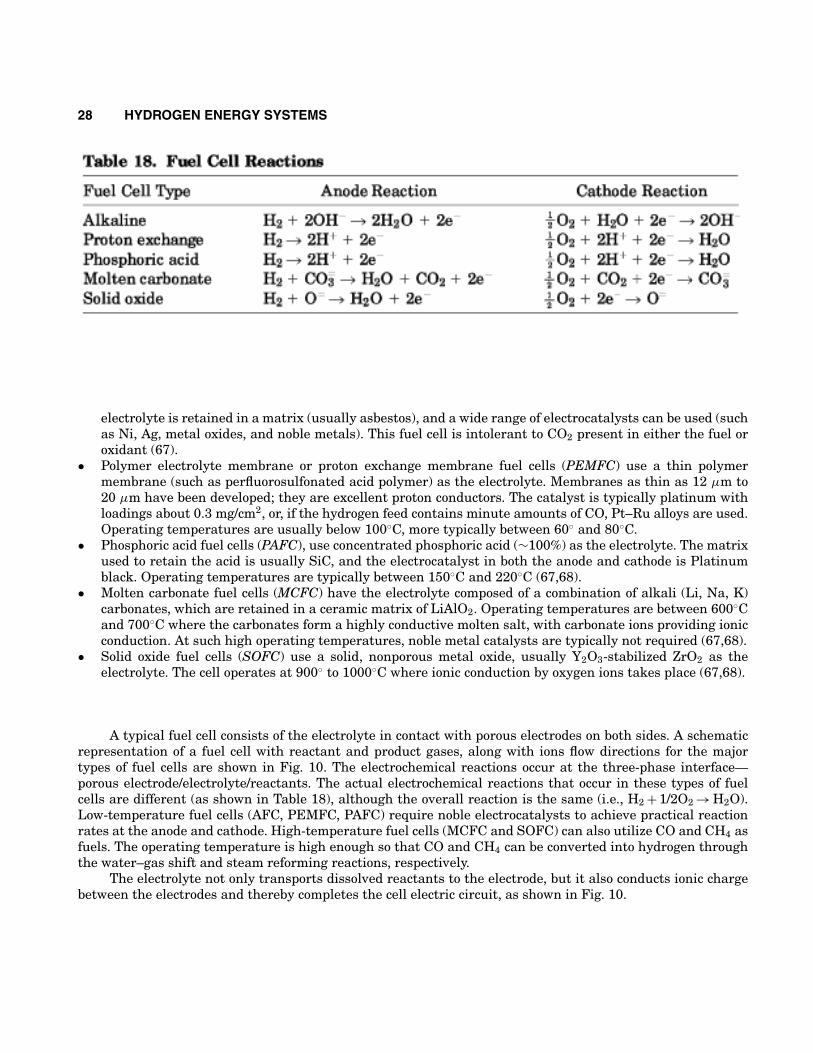
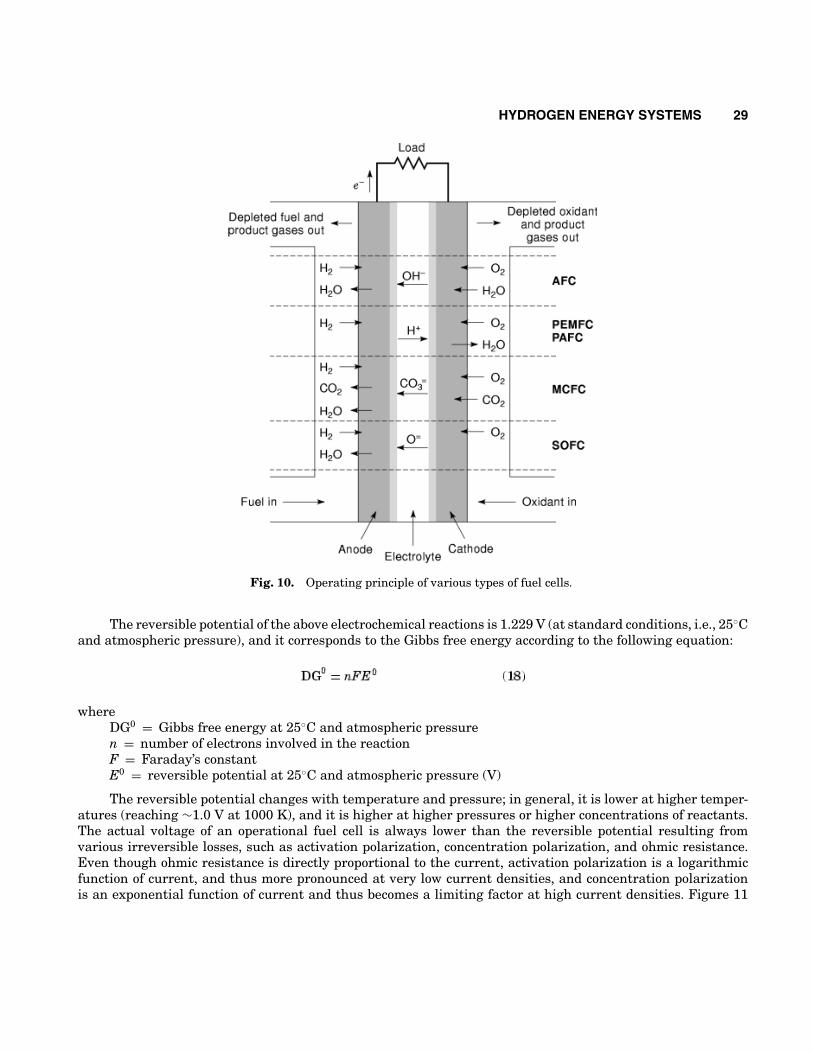
A typical fuel cell consists of the electrolyte in contact with porous electrodes on both sides. A schematicrepresentation of a fuel cell with reactant and product gases, along with ions flow directions for the majortypes of fuel cells are shown in Fig. 10. The electrochemical reactions occur at the three-phase interface—porous electrode/electrolyte/reactants. The actual electrochemical reactions that occur in these types of fuelcells are different (as shown in Table 18), although the overall reaction is the same (i.e., H2 + 1/2O2 → H2O).Low-temperature fuel cells (AFC, PEMFC, PAFC) require noble electrocatalysts to achieve practical reactionrates at the anode and cathode. High-temperature fuel cells (MCFC and SOFC) can also utilize CO and CH4 asfuels. The operating temperature is high enough so that CO and CH4 can be converted into hydrogen throughthe water–gas shift and steam reforming reactions, respectively.
The electrolyte not only transports dissolved reactants to the electrode, but it also conducts ionic chargebetween the electrodes and thereby completes the cell electric circuit, as shown in Fig. 10.
HYDROGEN ENERGY SYSTEMS 29
Fig. 10. Operating principle of various types of fuel cells.
The reversible potential of the above electrochemical reactions is 1.229 V (at standard conditions, i.e., 25◦Cand atmospheric pressure), and it corresponds to the Gibbs free energy according to the following equation:
whereDG0 = Gibbs free energy at 25◦C and atmospheric pressuren = number of electrons involved in the reactionF = Faraday’s constantE0 = reversible potential at 25◦C and atmospheric pressure (V)
The reversible potential changes with temperature and pressure; in general, it is lower at higher temper-atures (reaching ∼1.0 V at 1000 K), and it is higher at higher pressures or higher concentrations of reactants.The actual voltage of an operational fuel cell is always lower than the reversible potential resulting fromvarious irreversible losses, such as activation polarization, concentration polarization, and ohmic resistance.Even though ohmic resistance is directly proportional to the current, activation polarization is a logarithmicfunction of current, and thus more pronounced at very low current densities, and concentration polarizationis an exponential function of current and thus becomes a limiting factor at high current densities. Figure 11
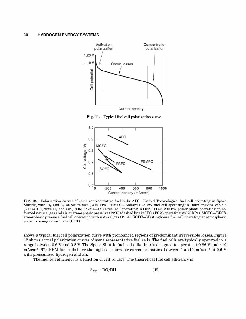
30 HYDROGEN ENERGY SYSTEMS
Fig. 11. Typical fuel cell polarization curve.
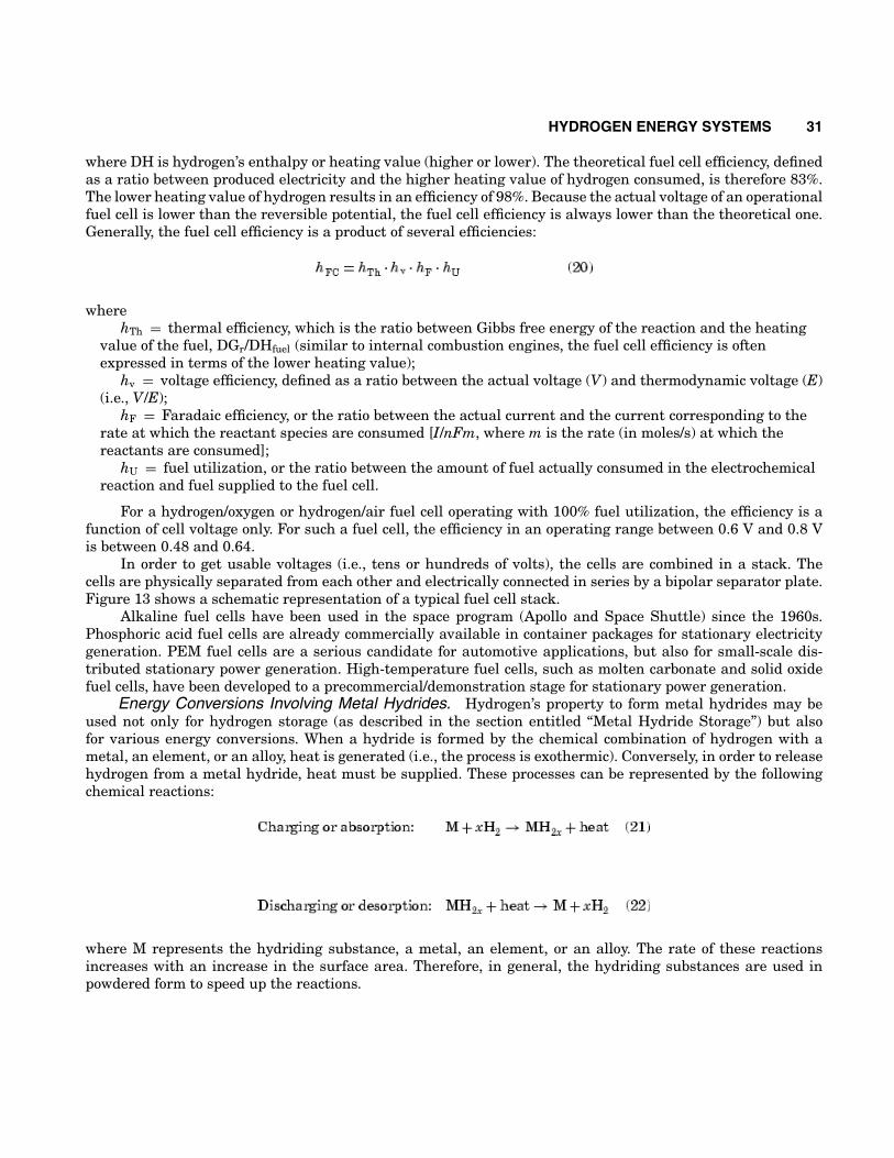
Fig. 12. Polarization curves of some representative fuel cells. AFC—United Technologies’ fuel cell operating in SpaceShuttle, with H2 and O2 at 80◦ to 90◦C, 410 kPa. PEMFC—Ballard’s 25 kW fuel cell operating in Daimler-Benz vehicle(NECAR II) with H2 and air (1996). PAFC—IFC’s fuel cell operating in ONSI PC25 200 kW power plant, operating on re-formed natural gas and air at atmospheric pressure (1996) (dashed line in IFC’s PC23 operating at 820 kPa). MCFC—ERC’satmospheric pressure fuel cell operating with natural gas (1994). SOFC—Westinghouse fuel cell operating at atmosphericpressure using natural gas (1991).
shows a typical fuel cell polarization curve with pronounced regions of predominant irreversible losses. Figure12 shows actual polarization curves of some representative fuel cells. The fuel cells are typically operated in arange between 0.6 V and 0.8 V. The Space Shuttle fuel cell (alkaline) is designed to operate at 0.86 V and 410mA/cm2 (67). PEM fuel cells have the highest achievable current densities, between 1 and 2 mA/cm2 at 0.6 Vwith pressurized hydrogen and air.
The fuel cell efficiency is a function of cell voltage. The theoretical fuel cell efficiency is
HYDROGEN ENERGY SYSTEMS 31
where DH is hydrogen’s enthalpy or heating value (higher or lower). The theoretical fuel cell efficiency, definedas a ratio between produced electricity and the higher heating value of hydrogen consumed, is therefore 83%.The lower heating value of hydrogen results in an efficiency of 98%. Because the actual voltage of an operationalfuel cell is lower than the reversible potential, the fuel cell efficiency is always lower than the theoretical one.Generally, the fuel cell efficiency is a product of several efficiencies:
wherehTh = thermal efficiency, which is the ratio between Gibbs free energy of the reaction and the heating
value of the fuel, DGr/DHfuel (similar to internal combustion engines, the fuel cell efficiency is oftenexpressed in terms of the lower heating value);
hv = voltage efficiency, defined as a ratio between the actual voltage (V) and thermodynamic voltage (E)(i.e., V/E);
hF = Faradaic efficiency, or the ratio between the actual current and the current corresponding to therate at which the reactant species are consumed [I/nFm, where m is the rate (in moles/s) at which thereactants are consumed];
hU = fuel utilization, or the ratio between the amount of fuel actually consumed in the electrochemicalreaction and fuel supplied to the fuel cell.
For a hydrogen/oxygen or hydrogen/air fuel cell operating with 100% fuel utilization, the efficiency is afunction of cell voltage only. For such a fuel cell, the efficiency in an operating range between 0.6 V and 0.8 Vis between 0.48 and 0.64.
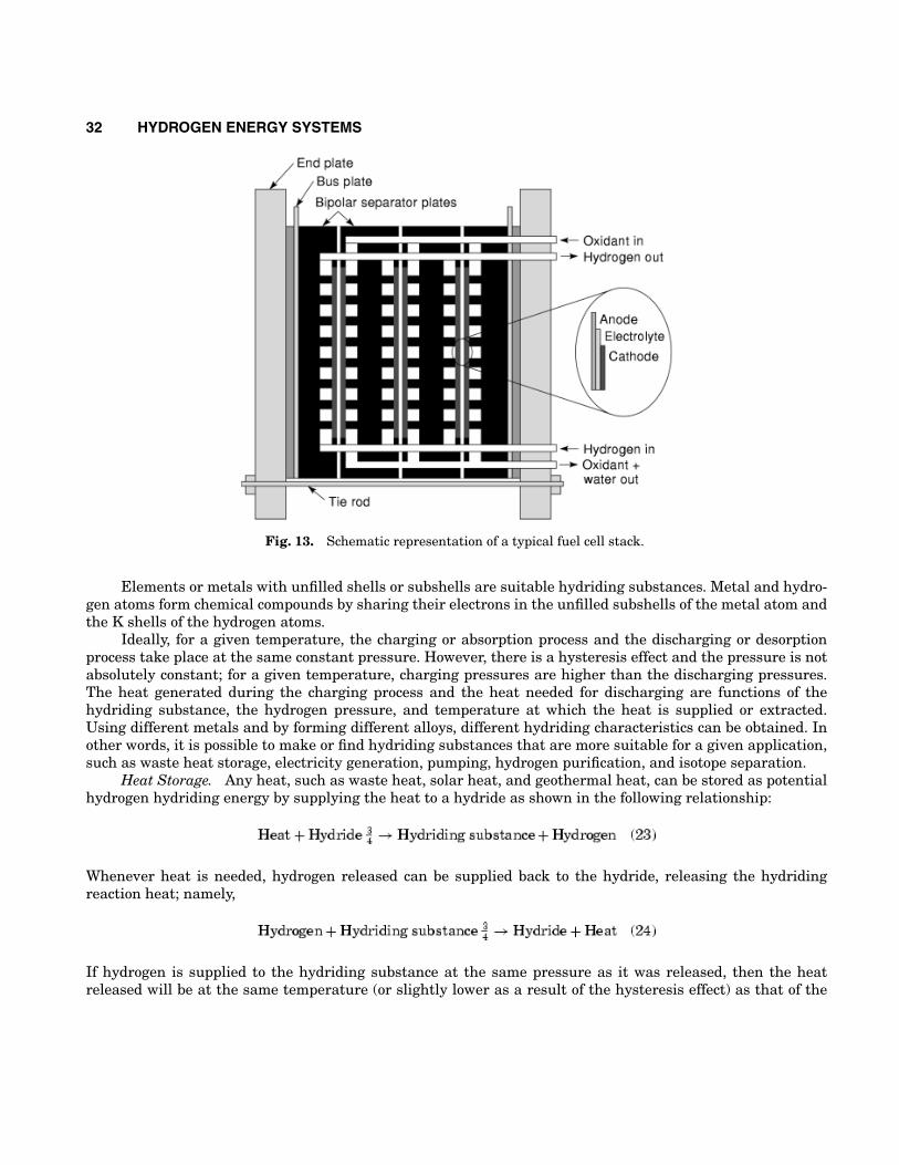
In order to get usable voltages (i.e., tens or hundreds of volts), the cells are combined in a stack. Thecells are physically separated from each other and electrically connected in series by a bipolar separator plate.Figure 13 shows a schematic representation of a typical fuel cell stack.
Alkaline fuel cells have been used in the space program (Apollo and Space Shuttle) since the 1960s.Phosphoric acid fuel cells are already commercially available in container packages for stationary electricitygeneration. PEM fuel cells are a serious candidate for automotive applications, but also for small-scale dis-tributed stationary power generation. High-temperature fuel cells, such as molten carbonate and solid oxidefuel cells, have been developed to a precommercial/demonstration stage for stationary power generation.
Energy Conversions Involving Metal Hydrides. Hydrogen’s property to form metal hydrides may beused not only for hydrogen storage (as described in the section entitled “Metal Hydride Storage”) but alsofor various energy conversions. When a hydride is formed by the chemical combination of hydrogen with ametal, an element, or an alloy, heat is generated (i.e., the process is exothermic). Conversely, in order to releasehydrogen from a metal hydride, heat must be supplied. These processes can be represented by the followingchemical reactions:
where M represents the hydriding substance, a metal, an element, or an alloy. The rate of these reactionsincreases with an increase in the surface area. Therefore, in general, the hydriding substances are used inpowdered form to speed up the reactions.
32 HYDROGEN ENERGY SYSTEMS
Fig. 13. Schematic representation of a typical fuel cell stack.
Elements or metals with unfilled shells or subshells are suitable hydriding substances. Metal and hydro-gen atoms form chemical compounds by sharing their electrons in the unfilled subshells of the metal atom andthe K shells of the hydrogen atoms.
Ideally, for a given temperature, the charging or absorption process and the discharging or desorptionprocess take place at the same constant pressure. However, there is a hysteresis effect and the pressure is notabsolutely constant; for a given temperature, charging pressures are higher than the discharging pressures.The heat generated during the charging process and the heat needed for discharging are functions of thehydriding substance, the hydrogen pressure, and temperature at which the heat is supplied or extracted.Using different metals and by forming different alloys, different hydriding characteristics can be obtained. Inother words, it is possible to make or find hydriding substances that are more suitable for a given application,such as waste heat storage, electricity generation, pumping, hydrogen purification, and isotope separation.
Heat Storage. Any heat, such as waste heat, solar heat, and geothermal heat, can be stored as potentialhydrogen hydriding energy by supplying the heat to a hydride as shown in the following relationship:
Whenever heat is needed, hydrogen released can be supplied back to the hydride, releasing the hydridingreaction heat; namely,
If hydrogen is supplied to the hydriding substance at the same pressure as it was released, then the heatreleased will be at the same temperature (or slightly lower as a result of the hysteresis effect) as that of the
HYDROGEN ENERGY SYSTEMS 33
heat supplied. However, by increasing the pressure of the hydrogen supplied, the temperature of the heatreleased can be increased; and conversely, by reducing the hydrogen pressure, the temperature of the heatreleased can be reduced. This means that metal hydrides can be used as heat pumps.
Electricity Storage. Hydriding substances can be used for electricity storage in two ways. In one of themethods, electricity (direct current) is used to electrolyze the water, and the hydrogen produced is stored in ahydriding substance. When electricity is needed, hydrogen is released from the hydriding substance by addingheat and using it in a fuel cell to produce direct current electricity. Heat from the fuel cell can be used to releasehydrogen from the metal hydride. In the second method, one electrode is covered with a hydriding substance(e.g., titanium nickel alloy). During the electrolysis of water, hydrogen produced on the electrode surface isimmediately absorbed by the hydriding substance covering the electrode. Then, when electricity is needed, theelectrolyzer operates in a reverse mode as a fuel cell producing electricity using the hydrogen released fromthe metal hydride.
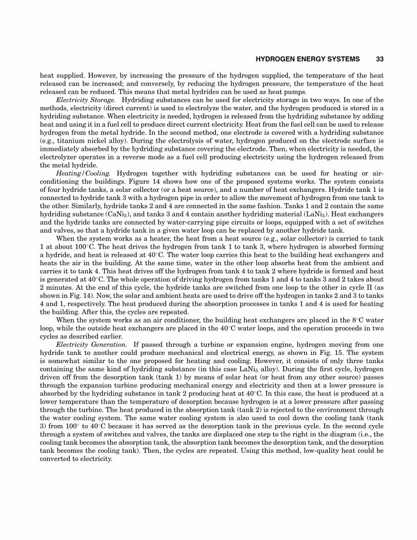
Heating/Cooling. Hydrogen together with hydriding substances can be used for heating or air-conditioning the buildings. Figure 14 shows how one of the proposed systems works. The system consistsof four hydride tanks, a solar collector (or a heat source), and a number of heat exchangers. Hydride tank 1 isconnected to hydride tank 3 with a hydrogen pipe in order to allow the movement of hydrogen from one tank tothe other. Similarly, hydride tanks 2 and 4 are connected in the same fashion. Tanks 1 and 2 contain the samehydriding substance (CaNi5), and tanks 3 and 4 contain another hydriding material (LaNi5). Heat exchangersand the hydride tanks are connected by water-carrying pipe circuits or loops, equipped with a set of switchesand valves, so that a hydride tank in a given water loop can be replaced by another hydride tank.
When the system works as a heater, the heat from a heat source (e.g., solar collector) is carried to tank1 at about 100◦C. The heat drives the hydrogen from tank 1 to tank 3, where hydrogen is absorbed forminga hydride, and heat is released at 40◦C. The water loop carries this heat to the building heat exchangers andheats the air in the building. At the same time, water in the other loop absorbs heat from the ambient andcarries it to tank 4. This heat drives off the hydrogen from tank 4 to tank 2 where hydride is formed and heatis generated at 40◦C. The whole operation of driving hydrogen from tanks 1 and 4 to tanks 3 and 2 takes about2 minutes. At the end of this cycle, the hydride tanks are switched from one loop to the other in cycle II (asshown in Fig. 14). Now, the solar and ambient heats are used to drive off the hydrogen in tanks 2 and 3 to tanks4 and 1, respectively. The heat produced during the absorption processes in tanks 1 and 4 is used for heatingthe building. After this, the cycles are repeated.
When the system works as an air conditioner, the building heat exchangers are placed in the 8◦C waterloop, while the outside heat exchangers are placed in the 40◦C water loops, and the operation proceeds in twocycles as described earlier.
Electricity Generation. If passed through a turbine or expansion engine, hydrogen moving from onehydride tank to another could produce mechanical and electrical energy, as shown in Fig. 15. The systemis somewhat similar to the one proposed for heating and cooling. However, it consists of only three tankscontaining the same kind of hydriding substance (in this case LaNi5 alloy). During the first cycle, hydrogendriven off from the desorption tank (tank 1) by means of solar heat (or heat from any other source) passesthrough the expansion turbine producing mechanical energy and electricity and then at a lower pressure isabsorbed by the hydriding substance in tank 2 producing heat at 40◦C. In this case, the heat is produced at alower temperature than the temperature of desorption because hydrogen is at a lower pressure after passingthrough the turbine. The heat produced in the absorption tank (tank 2) is rejected to the environment throughthe water cooling system. The same water cooling system is also used to cool down the cooling tank (tank3) from 100◦ to 40◦C because it has served as the desorption tank in the previous cycle. In the second cyclethrough a system of switches and valves, the tanks are displaced one step to the right in the diagram (i.e., thecooling tank becomes the absorption tank, the absorption tank becomes the desorption tank, and the desorptiontank becomes the cooling tank). Then, the cycles are repeated. Using this method, low-quality heat could beconverted to electricity.
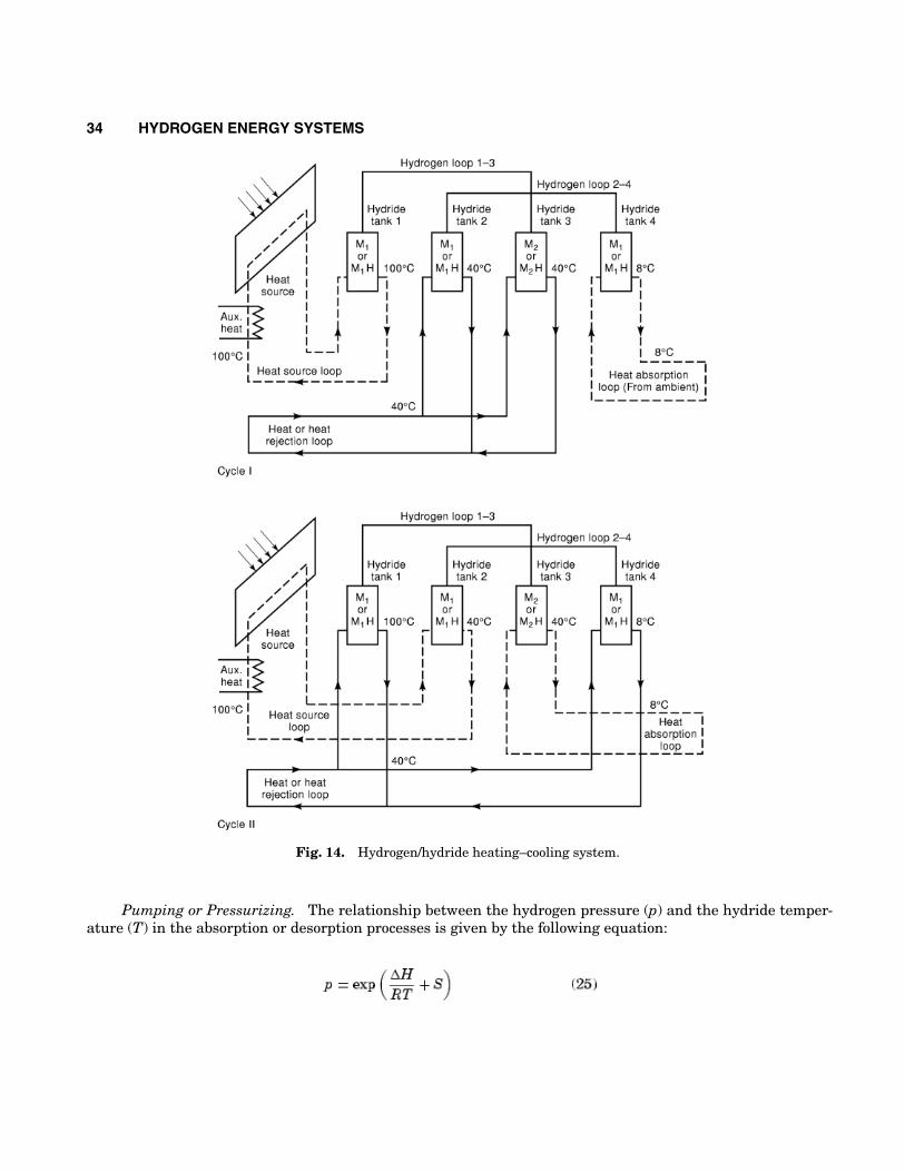
34 HYDROGEN ENERGY SYSTEMS
Fig. 14. Hydrogen/hydride heating–cooling system.
Pumping or Pressurizing. The relationship between the hydrogen pressure (p) and the hydride temper-ature (T) in the absorption or desorption processes is given by the following equation:
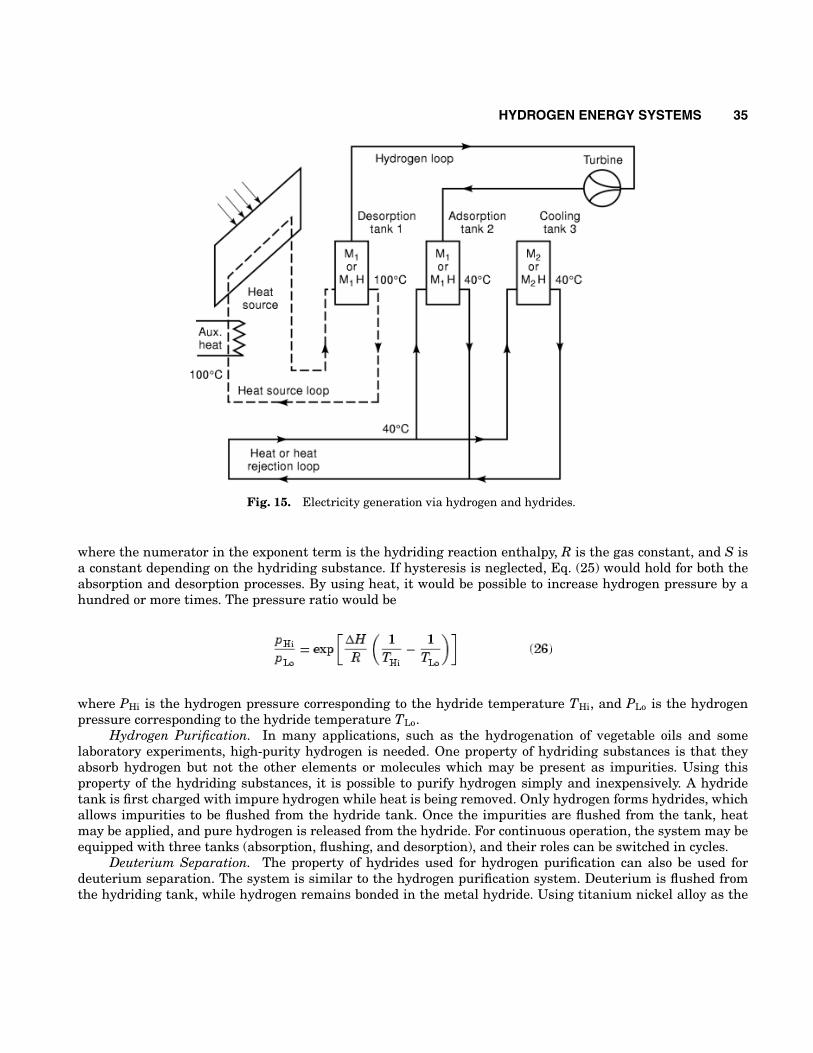
HYDROGEN ENERGY SYSTEMS 35
Fig. 15. Electricity generation via hydrogen and hydrides.
where the numerator in the exponent term is the hydriding reaction enthalpy, R is the gas constant, and S isa constant depending on the hydriding substance. If hysteresis is neglected, Eq. (25) would hold for both theabsorption and desorption processes. By using heat, it would be possible to increase hydrogen pressure by ahundred or more times. The pressure ratio would be
where PHi is the hydrogen pressure corresponding to the hydride temperature THi, and PLo is the hydrogenpressure corresponding to the hydride temperature TLo.
Hydrogen Purification. In many applications, such as the hydrogenation of vegetable oils and somelaboratory experiments, high-purity hydrogen is needed. One property of hydriding substances is that theyabsorb hydrogen but not the other elements or molecules which may be present as impurities. Using thisproperty of the hydriding substances, it is possible to purify hydrogen simply and inexpensively. A hydridetank is first charged with impure hydrogen while heat is being removed. Only hydrogen forms hydrides, whichallows impurities to be flushed from the hydride tank. Once the impurities are flushed from the tank, heatmay be applied, and pure hydrogen is released from the hydride. For continuous operation, the system may beequipped with three tanks (absorption, flushing, and desorption), and their roles can be switched in cycles.
Deuterium Separation. The property of hydrides used for hydrogen purification can also be used fordeuterium separation. The system is similar to the hydrogen purification system. Deuterium is flushed fromthe hydriding tank, while hydrogen remains bonded in the metal hydride. Using titanium nickel alloy as the
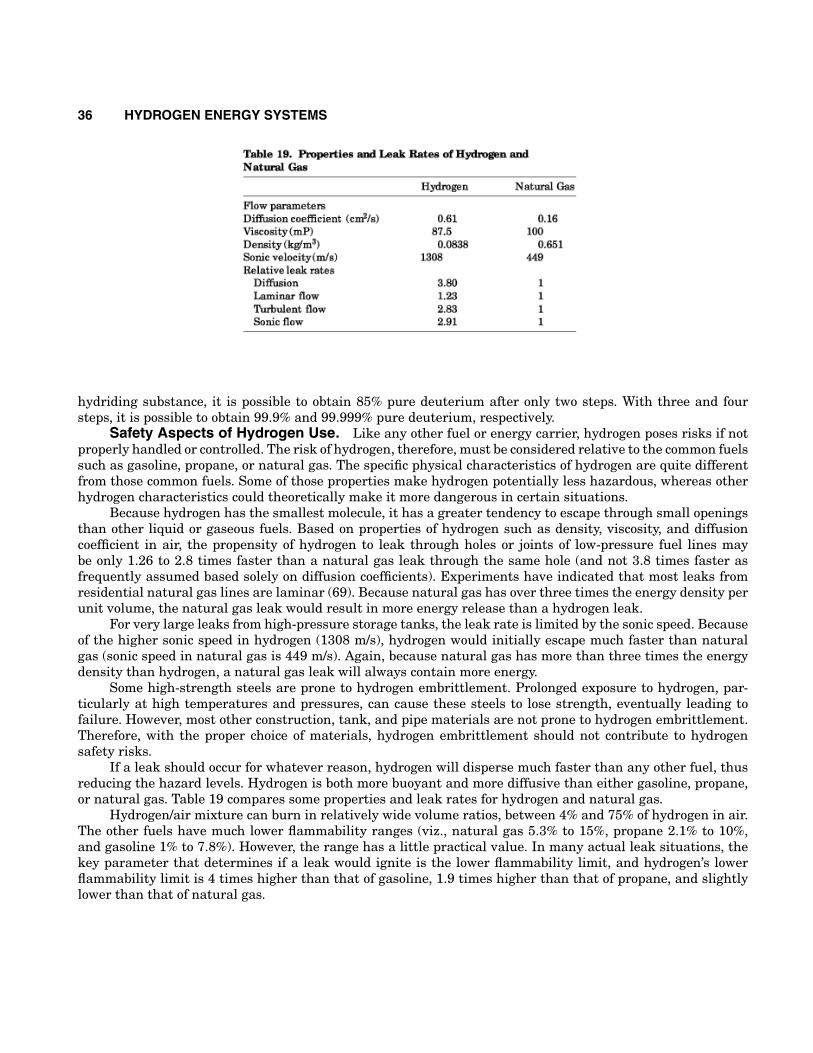
36 HYDROGEN ENERGY SYSTEMS
hydriding substance, it is possible to obtain 85% pure deuterium after only two steps. With three and foursteps, it is possible to obtain 99.9% and 99.999% pure deuterium, respectively.
Safety Aspects of Hydrogen Use. Like any other fuel or energy carrier, hydrogen poses risks if notproperly handled or controlled. The risk of hydrogen, therefore, must be considered relative to the common fuelssuch as gasoline, propane, or natural gas. The specific physical characteristics of hydrogen are quite differentfrom those common fuels. Some of those properties make hydrogen potentially less hazardous, whereas otherhydrogen characteristics could theoretically make it more dangerous in certain situations.
Because hydrogen has the smallest molecule, it has a greater tendency to escape through small openingsthan other liquid or gaseous fuels. Based on properties of hydrogen such as density, viscosity, and diffusioncoefficient in air, the propensity of hydrogen to leak through holes or joints of low-pressure fuel lines maybe only 1.26 to 2.8 times faster than a natural gas leak through the same hole (and not 3.8 times faster asfrequently assumed based solely on diffusion coefficients). Experiments have indicated that most leaks fromresidential natural gas lines are laminar (69). Because natural gas has over three times the energy density perunit volume, the natural gas leak would result in more energy release than a hydrogen leak.
For very large leaks from high-pressure storage tanks, the leak rate is limited by the sonic speed. Becauseof the higher sonic speed in hydrogen (1308 m/s), hydrogen would initially escape much faster than naturalgas (sonic speed in natural gas is 449 m/s). Again, because natural gas has more than three times the energydensity than hydrogen, a natural gas leak will always contain more energy.
Some high-strength steels are prone to hydrogen embrittlement. Prolonged exposure to hydrogen, par-ticularly at high temperatures and pressures, can cause these steels to lose strength, eventually leading tofailure. However, most other construction, tank, and pipe materials are not prone to hydrogen embrittlement.Therefore, with the proper choice of materials, hydrogen embrittlement should not contribute to hydrogensafety risks.
If a leak should occur for whatever reason, hydrogen will disperse much faster than any other fuel, thusreducing the hazard levels. Hydrogen is both more buoyant and more diffusive than either gasoline, propane,or natural gas. Table 19 compares some properties and leak rates for hydrogen and natural gas.
Hydrogen/air mixture can burn in relatively wide volume ratios, between 4% and 75% of hydrogen in air.The other fuels have much lower flammability ranges (viz., natural gas 5.3% to 15%, propane 2.1% to 10%,and gasoline 1% to 7.8%). However, the range has a little practical value. In many actual leak situations, thekey parameter that determines if a leak would ignite is the lower flammability limit, and hydrogen’s lowerflammability limit is 4 times higher than that of gasoline, 1.9 times higher than that of propane, and slightlylower than that of natural gas.
HYDROGEN ENERGY SYSTEMS 37
Hydrogen has a very low ignition energy (0.02 mJ), about one order of magnitude lower than other fuels.The ignition energy is a function of fuel/air ratio, and for hydrogen it reaches a minimum at about 25% to 30%.At the lower flammability limit, hydrogen ignition energy is comparable with that of natural gas (70).
Hydrogen has a flame velocity seven times faster than that of natural gas or gasoline. A hydrogen flamewould therefore be more likely to progress to deflagration or even detonation than other fuels. However,the likelihood of a detonation depends in a complex manner on the exact fuel/air ratio, the temperature, andparticularly the geometry of the confined space. Hydrogen detonation in the open atmosphere is highly unlikely.
The lower detonability fuel/air ratio for hydrogen is 13% to 18%, which is two times higher than that ofnatural gas and 12 times higher than that of gasoline. Because the lower flammability limit is 4%, an explosionis possible only under the most unusual scenarios (e.g., hydrogen would first have to accumulate and reach 13%concentration in a closed space without ignition, and only then an ignition source would have to be triggered).
Should an explosion occur, hydrogen has the lowest explosive energy per unit stored energy in the fuel,and a given volume of hydrogen would have 22 times less explosive energy than the same volume filled withgasoline vapor.
Hydrogen flame is nearly invisible, which may be dangerous because people in the vicinity of a hydrogenflame may not even know there is a fire. This may be remedied by adding some chemicals that will providethe necessary luminosity. The low emissivity of hydrogen flames means that near-by materials and people willbe much less likely to ignite and/or be hurt by radiant heat transfer. The fumes and soot from a gasoline firepose a risk to anyone inhaling the smoke, whereas hydrogen fires produce only water vapor (unless secondarymaterials begin to burn).
Liquid hydrogen presents another set of safety issues, such as the risk of cold burns and the increasedduration of leaked cryogenic fuel. A large spill of liquid hydrogen has some characteristics of a gasoline spill;however, it will dissipate much faster. Another potential danger is a violent explosion of a boiling liquidexpanding vapor in case of a pressure relief valve failure.
In conclusion, hydrogen appears to pose risks of the same order of magnitude as other fuels. In spite ofpublic perception, in many aspects hydrogen is actually a safer fuel than gasoline and natural gas. As a matterof fact, hydrogen has a very good safety record, as a constituent of the “town gas” widely used in Europe andthe United States in the 19th and early 20th century, as a commercially used industrial gas, and as a fuel inspace programs. There have been accidents, but nothing that would characterize hydrogen as more dangerousthan other fuels has occurred.
One of the most remembered accidents involving hydrogen is the Hindenburg dirigible disaster in 1937.However, hydrogen did not cause that accident, and hydrogen fire did not directly cause any casualties. Theaccident appears to have been caused by a static electricity discharge, and it was the balloon’s lining thatcaught fire first (71). Once hydrogen that the balloon was filled with for buoyancy (instead of helium as it wasoriginally designed to be filled with) was ignited, it burned (as any fuel is supposed to). However, hydrogenfire went straight up, and it did not radiate heat so the people in the gondola underneath the balloon werenot burned or suffocated. As a matter of fact, 56 survivors walked out of gondola when it landed and all thehydrogen and balloon structure burned out. Therefore, even in a worst case scenario accident, hydrogen provedto be a safe fuel.
Liquid Hydrogen
Hydrogen may be stored in gaseous, liquid, slush, and solid forms (metal hydrides). Every mode of storagehas its advantages and disadvantages in terms of cost, stability, convenience of usage, and energy density.Liquid hydrogen has several advantages over other storage modes, especially in terms of energy density andconvenience of utilization. However, several problems stand in the way of its large-scale production and long-term storage. This includes problems associated with energy consumed in liquefaction as well as boil-off losses
38 HYDROGEN ENERGY SYSTEMS
during storage and handling. Boil-off losses occur because of a variety of mechanisms such as ortho–paraconversion, thermal stratification and self pressurization, heat leaks, sloshing, and flashing. This section willreview some of these problems and discuss some of the prospects of large-scale liquid hydrogen production andutilization.
Introduction. Liquid hydrogen has many different uses, and its usefulness in a number of areas hasbeen demonstrated. Presently, liquid hydrogen is primarily used as a rocket fuel and is predestined for super-sonic and hypersonic space vehicles primarily because it has the smallest boiling point density and the highestspecific thrust of any known fuel. Its favorable characteristics include its high heating value per unit mass, itswide ignition range in hydrogen/oxygen or air mixtures, as well as its large flame speed and cooling capacitydue to its high specific heat which permits very effective engine cooling and cooling the critical parts of theouter skin (72,73). Liquid hydrogen has some other important uses such as in high-energy nuclear physicsand bubble chambers. The transport of hydrogen is vastly more economical when it is in liquid form, eventhough cryogenic refrigeration and special dewar vessels are required. Although liquid hydrogen can providemany advantages, its uses are restricted in part because liquefying hydrogen by existing conventional methodsconsumes a large amount of energy (around 30% of its heating value). Also, boil-off losses associated with thestorage, transportation, and handling of liquid hydrogen can consume up to 40% of its available combustionenergy. It is therefore important to search for ways that can improve the efficiency of the liquefiers and di-minish the boil-off losses. Improving liquefier efficiency not only helps to recover some of the aforementioned30% losses but can also contribute to reducing the other 40% losses caused by boil-off. This can be partiallyachieved by reliquefaction of the evaporated hydrogen. A significant improvement in the reliquefier efficiencyis required, however, in order to provide an economical reliquefaction process.
Liquid Hydrogen Production. The production of liquid hydrogen requires the use of liquefiers thatuse different principles of cooling. In general, hydrogen liquefiers may be classified as conventional, magnetic,or hybrid. Many types of conventional liquefiers exist such as the Linde–Hampson liquefiers, the Linde dual-pressure liquefiers, the Claude liquefiers, the Kapitza liquefiers, the Heylandt liquefiers, and those liquefiersusing the Collins cycle, just to name a few. Conventional liquefiers generally are made up of compressors,expanders, heat exchangers, and Joule–Thomson valves. Magnetic liquefiers, on the other hand, use the mag-netocaloric effect. This effect is based on the principle that some magnetic materials experience a temperatureincrease upon the application of a magnetic field and a temperature drop upon lifting the magnetic field. Themagnetic analog of several conventional liquefiers include the Brayton liquefiers, the Stirling liquefiers, and theactive magnetic regenerative (AMR) liquefier. Additional information on liquid hydrogen production methodscan be found in Sherif et al. (74).
Liquid Hydrogen Storage. As reported earlier, long-term storage of liquid hydrogen is associated withseveral problems primarily related to boil-off losses. Research on the mechanisms contributing to boil-off lossesin cryogenic hydrogen storage systems exists to varying degrees of sophistication depending on the natureof the boil-off mechanism. These mechanisms are (1) ortho–para conversion; (2) heat leak (shape and sizeeffect, thermal stratification, thermal overfill, insulation, conduction, radiation, cooldown), (3) sloshing, and(4) flashing. These mechanisms will be described in what follows.
Boil-Off Resulting from Ortho–Para Conversion. The hydrogen molecule is made up of two identicalatoms, each of which is composed of a nucleus of one proton and one neutron and an electron orbiting aroundthe nucleus. The rotational band in the vibration–rotation spectrum of hydrogen was early observed to showa weak–strong alteration in intensity. This led to the idea that two varieties of hydrogen exist. This idea wasrationalized by Heisenberg and Hund in terms of the possible combinations of the nuclear spins in the hydrogenmolecule (75).
At high temperatures, the equilibrium mixture consists of 75% ortho-hydrogen and 25% para-hydrogen.Hydrogen of this composition is termed normal and is in equilibrium at room temperature and above. At 0 K,on the other hand, all the molecules must be in a rotational ground state at equilibrium. Therefore, all thehydrogen molecules at equilibrium should be in the para state at absolute zero. Pure para-hydrogen may be

HYDROGEN ENERGY SYSTEMS 39
prepared at equilibrium, but the maximum possible concentration of ortho-hydrogen is 75% under equilibriumconditions. Many of the thermophysical properties of normal and para-hydrogen are significantly different fromeach other. These differences have often been taken advantage of in analyses involving hydrogen. For instance,at 120 K to 190 K, the thermal conductivity of para-hydrogen is 50% more than that of ortho-hydrogen. Thethermal conductivity can, therefore, be used to determine the ortho–para ratio of a hydrogen sample (76).
By cooling hydrogen gas from room temperature to the nbp (normal boiling point), the ortho-hydrogenconverts to para-hydrogen spontaneously. The decrease of ortho concentration should be from 75% to 0.2%.Because the percentage of the ortho–para composition is temperature-dependent, and because, in the lique-faction process, the temperature continuously decreases, one of the questions that should arise pertains to therate of conversion. The conversion of a nonequilibrium ortho–para composition to an equilibrium compositionis a very slow process in the absence of a catalyst. This mode of conversion (i.e., in the absence of a catalyst) iscalled self-conversion.
The self-conversion rate is also a function of temperature. At the nbp of air, the half-life of conversion isgreater than one year, whereas at 923 K and a 0.0067 MPa the half-life is on the order of 10 min. The half-lifeperiod is defined as the amount of time required to convert half of the excess ortho (or para) composition presentat the starting time (76).
The conversion of ortho-hydrogen to para-hydrogen is an exothermic reaction. The heat of conversion isrelated to the change of momentum of the hydrogen nucleus when the direction of spin changes. The amountof heat given off in this conversion process is temperature-dependent. The heat of conversion is greater thanthe latent heat of vaporization of normal and para-hydrogen at the nbp. If the unconverted normal hydrogenis placed in a storage vessel, the heat of conversion will be released within the container, which leads to theevaporation of the liquid. Because of these peculiarities in the physical properties of hydrogen, the boil-off ofthe stored liquid will be considerably larger than what one would be able to determine from calculations basedon ordinary heat leak to the storage tank.
In order to minimize the storage boil-off losses, the conversion rate of ortho-hydrogen to para-hydrogenshould be accelerated with a catalyst that converts the hydrogen during the liquefaction process (77,78,79,80).In the presence of a catalyst that is well mixed with hydrogen, the reaction approaches a first-order one for thegas phase. If the catalyst is added to the liquid phase, the reaction becomes a zero-order one (81).
The transformation can be catalyzed by a number of surface active (or paramagnetic) species. A convenientway is to absorb normal-hydrogen on active charcoal cooled with liquid hydrogen and then pump off theequilibrium mixture. The conversion may take only a few minutes if a highly active form of charcoal is used(75), but the conversion effectiveness appears to depend on the presence of an absorbed layer of oxygen, which,for thoroughly purified hydrogen, may not be available (77). Other suitable ortho–para catalysts are metals suchas tungsten or nickel, any paramagnetic oxides like chromium or gadolinium oxides, and other paramagneticsubstances like NO2, ferric hydroxide gel, and nickel silicate. These catalysts are capable of enabling almostcomplete conversion to be achieved in a few minutes. In paramagnetic fields during a homogeneous conversionprocess (using paramagnetic gases or by passing hydrogen through solutions containing paramagnetic ions),the nuclear spin is reversed without breaking the H H bond. This suggests that strongly paramagnetic speciessuch as Gd3+ are highly effective. It has been shown that paramagnetic catalysis conversion is accelerated bythe action of an externally applied magnetic field. This effect tends to achieve saturation in a field of about1000 Oersted (79577 A/m) (75). In a magnetocaloric liquefier, there is a good chance of taking advantage ofthis phenomenon primarily because both the magnetic ions and the external magnetic field are available, thusmaking a good design the only prerequisite for achieving a fast and economic conversion.
The use of a catalyst usually results in a larger refrigeration load and consequently in an efficiency penaltyprimarily because the heat of conversion must be removed. The time for which hydrogen is to be stored usuallydetermines the optimum amount of conversion. For use within a few hours, no conversion is necessary. Forexample, large-scale use of liquid hydrogen as a fuel for jet aircraft is one of those cases where conversion is notnecessary because utilization of the liquid is almost a continuous process and long-term storage is therefore not
40 HYDROGEN ENERGY SYSTEMS
needed (80). For some other uses, a partial conversion might be required to create more favorable conditions. Itshould be noted that, for every initial ortho concentration, there exists a unique curve for boil-off of hydrogenwith respect to time.
The heat of conversion at higher temperatures is small (at 300 K, the heat of conversion is 270 kJ/kg) andincreases as the temperature decreases, where it reaches 519 kJ/kg at 77K, the nbp for liquid nitrogen. Fortemperatures lower than the nbp of nitrogen, the heat of conversion remains constant (523 kJ/kg). However, theequilibrium percentage of para-hydrogen at the nbp is 50%. Therefore, in order to produce equilibrium liquidhydrogen, 50% of hydrogen must be converted from ortho to para at temperatures lower than liquid nitrogentemperatures. Because the heat of conversion is almost constant for temperatures lower than those of liquidnitrogen, the refrigeration load required to remove the heat of conversion should be almost constant at differenttemperatures. Ideal refrigeration requires that the energy needed for the same amount of refrigeration loadbe temperature-dependent. This suggests that, in order to operate at an optimum power, it is necessary tohave continuous conversion, especially for temperatures lower than those of liquid nitrogen. By continuousconversion, up to 15% energy saving may be achieved.
Boil-Off Resulting from Heat Leak.Reservoir Shape and Size Effect. Hydrogen is usually transported in large quantities by truck tankers
of 30 m3 to 60 m3 capacity, by rail tank cars of 115 m3 capacity, and by barge containers of 950 m3 capacity(82). Liquid hydrogen storage vessels are usually available in sizes ranging from one liter dewar flasks usedin laboratory applications to large tanks of 5000 m3 capacity. The National Aeronautics and Space Adminis-tration (NASA) typically uses large tanks of 3800 m3 capacity (25 m in diameter) (83). The total boil-off ratefrom such dewars is approximately 600,000 LPY (liters per year), which is vented to a burn pond. The heatleakage losses are generally proportional to the ratio of surface area to the volume of the storage vessel (S/V).The most favorable shape is therefore spherical because it has the least surface to volume ratio. Sphericalshape containers have another advantage. They have good mechanical strength because stresses and strainsare distributed uniformly. In large sizes, spherical containers are expensive because of their manufacturingdifficulty. They are often used for on-site large volume storage, however.
Storage vessels may also be constructed in other shapes such as cylindrical, conical, or any combination ofthese shapes. Cylindrical vessels are usually required for transportation of liquid hydrogen by trailers or railwaycars because of limitations imposed on the maximum allowable diameter of the vessel. For normal highwaytransportation, the outside diameter of the vessel cannot exceed 2.44 m. From an economics standpoint,cylindrical vessels with either dish, elliptical, or hemispherical heads are very good, and their S/V ratios areonly about 10% greater than that of the sphere (84).
Because boil-off losses resulting from heat leak are proportional to S/V as reported earlier, the evapora-tion rate will diminish drastically as the storage tank size is increased. For double-walled vacuum-insulatedspherical dewars, boil-off losses are typically 0.3% to 0.5% per day for containers having a storage volume of50 m3, 0.2% for 103 m3 tanks, and about 0.06% for 19,000 m3 tanks (85). Obviously, the larger the size of thedewar, the smaller the cost per unit volume of storage. Interestingly enough, the rate of evaporation does notsubstantially decrease with increasing the size of the container for cylindrical vessels of constant diameter.
Thermal Stratification and Thermal Overfill. Stratification is the existence of a fluid at different tem-peratures within one vessel. Heat transfer from the sidewalls and bottom to a liquid hydrogen storage vesselwill always result in an increase of the sensible enthalpy of the liquid. When the heat flux is small enough andthe inside wall of the vessel is smooth, boiling is unlikely to occur (77). In this case, the added energy tends toget distributed nonuniformly because the imposed heat flux usually produces a free convective flow. The warmliquid hydrogen becomes buoyant and rises to the top. With the passage of time, the lower boundary of thestratified region moves toward the bottom of the vessel. Because the warm liquid rises to the surface, it is notuncommon to have the temperature at the top layers rise much more rapidly than that of the bulk liquid (84).As a consequence, the upper layers are more likely to experience a relatively large vapor pressure increase,whereas the lower layers experience little or no vapor pressure change. This thermal stratification creates a
HYDROGEN ENERGY SYSTEMS 41
vessel pressure corresponding to a temperature greater than the average liquid temperature because the tankpressure is mostly determined by the vapor pressure of the free surface. This in turn greatly reduces the lengthof liquid storage time without having to vent the vapor. Naturally, this leads to a decrease in the lock-up time.The stratification in temperature is stable because the warmer liquid has the lower density, in addition to thefact that liquid hydrogen is a poor thermal conductor (84).
Thermal overfill is a phenomenon that occurs when one of the following conditions exists.
(1) The average specific enthalpy of the liquid is greater than that of the saturation temperature, in whichcase the liquid boil-off from the vented dewars is found to be nonuniform. This can be attributed to theunstable stratification which occurs in vented dewars as a result of a sudden lowering of atmosphericpressure (generally, the liquid becomes superheated in the lower region, while the surface temperatureremains saturated, which leads to generating instant vapor of large quantities).
(2) The operating pressure of the tank is less than that corresponding to the saturation temperature of thefeed liquid, in which case only the surface layer is able to respond to the new operating pressure. If thesurface layer is distributed by some means, for instance by top-loading more liquid, the underlying liquidmay be brought into rapid equilibrium, and that, in turn, would cause a rapid boil-off (77,86).
One way to decrease boil-off losses resulting from stratification and thermal overfill is by employinghigh-conductivity plates (conductors) installed vertically in the vessel. The plates produce heat paths of lowresistance between the bottom and top of the vessel and can operate most satisfactorily in eliminating tem-perature gradients and excessive pressures. Another way is to pump the heat out and maintain the liquidat subcooled or saturated conditions. An ideal refrigeration system to perform this task can be an efficientmagnetic refrigerator. The magnetic refrigerator is very suitable for this job because of its relatively higherefficiency, compactness, lower price, and reliability (87,88,89,90,91,92,93,94,95).
Barclay (88) proposed a magnetic refrigerator that can be used for the reliquefaction of the hydrogenvapor. This design can be modified and used for the preceding cases. In order to perform the refrigerationeffectively, a thermal valve is needed to permit heat flow when there is superheat and to stop heat flow whenthere is no superheat (86).
Insulation and Conduction Through Supports. Liquid hydrogen containers are usually of three types:double-jacketed vessels with liquid nitrogen in the outer jacket, superinsulated vessels with either a reflectingpowder or multilayer insulation, and containers with vapor-cooled shields employing super insulation. Al-though multilayer insulation (MLI) provides for a low boil-off rate, the addition of a vapor-cooled shield (VCS)will lower the boil-off losses even further. A VCS is a type of insulation that takes the vapor boil-off and passesit past the tank before being reliquified or vented. Published data indicate that a reduction of more than 50%in boil-off may be achieved for a 45,045 kg liquid hydrogen cryogenic facility with a VCS than without one.Brown (96) showed that locating the VCS at half the distance from the tank to the outer surface of a 10.16 cmMLI of a 45,045 kg facility would reduce the boil-off by 10%. A dual VCS system on the tank would improvethe performance by 40% over a single VCS. Brown (96) also showed that the preferred locations for the innerand outer shields in a dual VCS system are 30% and 66% of the distance from the tank to the outer surface ofthe MLI.
Mechanical supports that connect the inner and outer vessel of double-walled vacuum tanks are anintegral part of the insulation problem, primarily because of the heat influx that can be conducted to the innervessel. One way to diminish these boil-off losses is to cool the support employing the produced hydrogen vaporcontinuously in a counterflow fashion.
In practice, the thermal conductivity of the support varies with temperature, and there exists difficultyin manufacturing a continuous heat exchange surface in the temperature range of interest. In this case, asuccession of discrete cooling stations provides for a better design. Bejan (97,98,99) introduced an optimization
42 HYDROGEN ENERGY SYSTEMS
method for finding the location and the temperature of the cooling stations, and he used that procedure inorder to optimize helium boil-off losses.
Another optimization of boil-off losses can be considered by changing the value of the heat sink temper-ature from 20.4 K to 33 K (critical temperature) and examining the temperature at which the boil-off rateis minimum. This is primarily because, as the storage temperature increases, the amount of heat leak and,consequently, the boil-off losses decrease. On the other hand, the latent heat of vaporization decreases withdecreasing storage temperature which contributes to increasing the boil-off. Thus, there should be an opti-mum storage temperature or pressure that balances the aforementioned effects. Employing this procedure, theoptimum temperature and pressure of the hydrogen vessel may be determined.
Boil-Off Resulting from Sloshing. Another process that leads to boil-off during liquid hydrogen trans-portation by tankers is sloshing. Sloshing is the motion of liquid in a vessel caused by acceleration or de-celeration. Because of different types of acceleration and deceleration, there exist different types of sloshing.Acceleration causes the liquid to move to one end and then reflect from that end, thus producing a hydraulicjump. The latter then travels to the other end, thus transforming some of its impact energy to thermal energy.The thermal energy dissipated eventually leads to an increase in the evaporation rate of the liquid (77,84). Theinsertion of traverse or antislosh baffles not only restrains the motion of the liquid, thus reducing the impactforces, but also increases the frequency above the natural frequency of the tanker (77,81).
Boil-Off Resulting from Flashing. Another source of boil-off is flashing. This problem occurs when liquidhydrogen, at a high pressure (2.4 to 2.7 atm), is transferred from trucks and rail cars to a low-pressure dewar(1.17 atm). This problem can be reduced if transportation of liquid hydrogen is carried out at atmosphericpressures. Furthermore, some of the low-pressure hydrogen can be captured and reliquefied. One of the bestsystems that can be selected for reliquefaction is one that employs a magnetic refrigerator as an external cycle.Another suitable cycle can be the Claude cycle with a saturated-vapor compressor and a wet expander. Thesystem operates best if the sink is a liquid nitrogen bath.
One other method, which is proposed by NASA, is to capture some of this low-pressure hydrogen by metalhydrides and then reliquefy the hydrogen vapor. According to this scheme, a liquefier with a capacity of 40 tonsper day (TPD) would be necessary to make up for the losses. This idea was considered expensive and was laterrejected.
Concluding Remarks on Liquid Hydrogen. This section addressed the production, storage, andutilization of liquid hydrogen. More research is probably needed to address some of the fundamental issuesthat are relevant to the efficient utilization and storage of liquid hydrogen. Additional information on liquidhydrogen storage can be found in Gursu et al. (100,101).
Slush Hydrogen
Slush hydrogen is a mixture of liquid and frozen hydrogen in equilibrium with the gas at the triple point.Slush hydrogen is expected to be the primary propellant for the National Aero-Space Plane (NASP) becauseof its potential in reducing its physical size and significantly cutting the projected gross liftoff weight. Thissection provides an overview of slush hydrogen production methods and reviews the current state of knowledgeregarding slush hydrogen utilization.
Introduction. Hydrogen has become an important rocket fuel despite the problems associated with itsuse. Some of these problems include its low density, temperature stratification, short holding time caused byits low latent heat, hazards associated with high vent rates, and unstable flight conditions caused by sloshingof the liquid in the fuel tank. Rapial and Daney (102) report that two techniques can completely eliminate someof these undesirable features and partially eliminate the others. One is the production of liquid–solid hydrogenmixtures “slush hydrogen” by further refrigeration of the liquid. The other is the gelation of liquid hydrogenby the addition of a fine particle gelling substance.

HYDROGEN ENERGY SYSTEMS 43
Slush hydrogen is a mixture of liquid and frozen hydrogen in equilibrium with the gas at the triple point,13.8 K. The density of the icelike form is about 20% higher than that of the boiling liquid. To obtain the icelikeform, one must remove the heat content of the liquid at 20.3 K until the triple point is reached and then removethe latent heat of fusion. The “cold content” of the icelike form of hydrogen is some 25% higher than that ofthe saturated vapor at 20.3 K. Justi (103) reports that in producing the slush hydrogen, in comparison withthe icelike form, one loses part of the increase in density and cold storage, but in mixing the icelike form withliquid hydrogen, one obtains a medium that is transportable in pipelines. Slush hydrogen can be produced fromliquid hydrogen with the help of a vacuum pump and expansion through a jet (103).
Baker and Matsch (104) gave a tabulated comparison among the properties of liquid and slush hydrogen.According to them, the smaller enthalpy of slush hydrogen reduces the evaporation losses during storage andtransport and as a consequence permits longer storage without venting. The increased density permits groundtransport equipment to carry 15% greater loads; for space vehicles, a given fuel load can be carried in tankagethat is 13% smaller in volume.
Kandebo (105) reported that slush hydrogen is expected to be the primary propellant for the NASP. Hementioned that using slush instead of liquid hydrogen reduces the physical size of the NASP and cuts theprojected gross liftoff weight by up to 30%. The freeze–thaw process, which is the most used slush productionprocess, and the auger process, which is relatively new, were discussed and compared. One expensive alternativemethod to pressurize tanks was also mentioned. This alternative is to pressurize tanks with a combination ofhelium and hydrogen because helium does not condense at slush hydrogen storage temperatures and is notvery dense.
Justi (103) reported that the slushlike form of hydrogen has the advantage of a greater “cold content”compared to liquid hydrogen. The disadvantage of slush hydrogen lies in the present state of the technologyfor its production, which is not yet well advanced, so that it is impractical to calculate a realistic price. Justiargues, however, that the production cost of slush hydrogen now and in the near future is greater than theliquefaction costs of hydrogen because of the larger energy use involved.
Sindt (106) studied the characteristics of slush hydrogen preparation, storage, transfer and instrumenta-tion. In that study, slush preparation by intermittent vacuum pumping was discussed. Slush was aged 100 h,during which time the solid particle size and structure were observed. The solid particle structure was foundto change dramatically during aging, even though the changes in the particle size were insignificant. Sindtalso mentioned that slush with over 50% solid content could be transferred and pumped with losses similar tothose in triple-point liquid hydrogen if the Reynolds numbers were high enough.
Voth (107) reported on a slush hydrogen production method with an auger rotating inside a brass tuberefrigerated with liquid helium. The auger was reported to produce small particles from the cryogens on acontinuous basis so that the resulting slush mixture could be transferred and stored. He also reported that theauger is capable of producing slush at pressures higher than the triple-point pressure of the cryogen.
Methods for determining the quality of liquid–solid hydrogen mixtures, along with relevant thermody-namic analyses were discussed by Daney and Mann (108) and Mann et al. (109). Properties of liquid and slushhydrogen and their applications were discussed by Smith (110) and Angus (111). The flow characteristics ofslush hydrogen with different solid contents were examined by Sindt and Ludtke (112) and by Sindt et al. (113).The latter study reported on experimental results in which a second component was added to liquid hydrogento determine the effect produced by the freeze–thaw process on the size of the solid particles. Perrel and Haase(114) developed a computer simulation method to describe the self-catalysis of ortho-hydrogen molecules. Thesimulations were performed on a small computer using Monte Carlo techniques. Roder (115) studied the phasetransitions in solid hydrogen and suggested that, except for the lambda transition that occurs at low tempera-tures in solid hydrogen, and involves a change from hexagonal close-packed (hcp) to face-centered cubic (fcc),there may be an additional phase transition in solid hydrogen.
Although current interest in liquid–solid mixtures of hydrogen as a potential rocket propellant has lead totheoretical and experimental investigations of its characteristics, there is still a lot of potential for additional

44 HYDROGEN ENERGY SYSTEMS
investigations. For example, the problem of transferring heat to slush hydrogen along with solid densitystratification in large containers needs to be investigated more thoroughly.
Production of Slush Hydrogen. Several successful methods for producing solids from liquid–solidmixtures were reported in the literature. However, if the preparation method is to be usable, it must work insystems of all sizes and still meet certain basic criteria that create a process that is thermodynamically efficientand reproducible. The process should also be able to produce a mixture with enough fluidity to transfer throughexisting systems and with sufficient solid content so that the density and heat capacity are significantly greaterthan those for the normal boiling point liquid.
Freeze-Thaw Method. Sindt (106) summarized the basic principles of the freeze–thaw method and itsfeasibility. Two of the methods reported by Sindt involve the formation of solid particles by spraying precooledliquid into an environment well below the triple-point pressure and inducing solid formation by allowingprecooled helium gas to flow through a triple-point temperature liquid. The spray technique produced a verylow density solid particle, which had to be partially melted to form a liquid–solid mixture. The techniqueof allowing helium to flow through the liquid-produced solid by reducing the partial pressure of hydrogenbelow its triple-point pressure which resulted in a clear, rigid tube of solid forming around the helium bubbletrain. The solid was found not to be convertible to a mixture without further treatment such as crushing.Sindt found that a more desirable preparation method was to evacuate the ullage over the liquid, whichcreated a solid layer at the liquid surface. The solid layer produced had a texture that was very dependentupon the rate of vacuum pumping. Low pumping rates produced a dense, nearly transparent layer of solid.Subsequent breaking of the solid left large rigid pieces that formed inhomogeneous mixtures even with vigorousmixing. Higher pumping rates produced a solid layer that was porous and consisted of agglomerates of looselyattached fine solid particles. The solid layer was found to be easily broken and mixed with the liquid to form ahomogeneous liquid–solid mixture that could be defined as slush. Sindt discovered, however, that solids couldnot be continuously generated at the liquid surface without vigorous mixing.
Sindt (106) also reported on a continuous preparation method, which he developed, capable of formingsolid layers in cycles by periodic vacuum pumping. During the pumping (pressure reduction) portion of thecycle, the solid layer formed as previously described. When the pumping was stopped, the solid layer melted andsettled into the liquid, forming slush. Although mixing was not necessarily required, the preparation methodwas accelerated by some mechanical mixing which helped break the layer of solids. This technique has beencalled the freeze–thaw process.
In the same study, Sindt was able to determine the acceptable limits of vacuum pumping rates for freeze–thaw slush production. He found that low pumping rates were unacceptable because of the texture of the solidproduced. Very high pumping rates were also found to be undesirable because liquid droplets were carriedinto the warm regions of the system by the velocity of the evolving gas. The evaporation of these dropletswas, therefore, considered a loss to the preparation of solid. Sindt also determined the rate that producessolids that are easily transformable into slush by measuring the evolved gas during many cycles of freeze–thaw preparation. This rate was determined to be 0.9 m3s− 1/m2 of liquid surface area at vacuum pump inletconditions of 300 K and 6.9 kNm− 2. This was also found to be the pumping rate during the evacuation phaseof the freeze–thaw cycle. He concluded that the range of the vacuum pumping rate for satisfactory slushproduction was 0.8 m3s− 1/m2 to 1.2 m3s− 1/m2 of liquid surface area. Pumping rates in that range were foundto result in an efficient exchange of energy between the evaporating and freezing liquids. The efficiency of thisexchange of energy is best illustrated by the experimentally determined irreversibility reported by Daney andMann (108), which was found to be less than 3.4%. Pumping rates within this range have been used to produceslush of solid fractions to 0.45 in vessels 10 cm to 76 cm in diameter.
According to Voth (107), although the freeze–thaw production method proved to be technically feasible andfully developed, it was shown to have disadvantages. These disadvantages include the fact that the freeze–thawprocess is a batch process and that it operates at the triple-point pressure of the cryogen. For hydrogen, thispressure was estimated to be 0.07 bars absolute, a pressure capable of drawing air through inadvertent leaks
HYDROGEN ENERGY SYSTEMS 45
in the system. The air could be thought of as presenting a potential safety problem in a hydrogen system. Vothalso showed that the freeze–thaw process required either costly equipment to recover the generated triple-pointvapor or the loss of approximately 16% of the normal boiling-point liquid hydrogen and approximately 24% ofthe normal boiling-point liquid oxygen if the vapor was discarded.
Auger Method. Voth (107) reported on a study for producing liquid–solid mixtures of oxygen or hydrogenusing an auger. He described an auger used to scrape frozen solid from the inside of a refrigerated brass tubein order to produce slush hydrogen. He showed that slush hydrogen could be continuously produced by thismethod, and because it could be immersed in liquid, slush was produced at pressures above the triple-pointpressure. Voth was also able to produce the increased pressure pneumatically or by generating a temperaturestratification near the surface of the liquid. He observed that the auger system produced particles in the sizerealm of the particle produced by the freeze–thaw method so that, like the freeze–thaw-produced slush, theauger-produced slush could be readily transferred and stored.
According to Voth (107), the surface freezing occurring in the freeze–thaw production process is thermo-dynamically reversible. In contrast, the freezing process in the auger is irreversible because a temperaturedifference must exist between the refrigerant and the freezing cryogen, and the energy added to scrape thesolid cryogen out of the brass tube must be removed by the refrigerant. Voth argued that in spite of theseirreversibilities, the auger system was found to require less energy to produce slush hydrogen than a particlefreeze–thaw system. He reported that the temperature difference required refrigeration temperatures belowthe triple-point temperature of hydrogen so that a gaseous or liquid helium refrigerator was required for theauger.
Although this method was determined to offer the advantage of operating above atmospheric pressures(an important consideration in lowering the possibility of oxygen intrusion into the slush), it was shown tohave the disadvantage of using expensive helium coolant.
Quality Determination. A thermodynamic analysis of the freeze–thaw production process for formingmixtures of slush developed by Mann et al. (109) showed that the measurement of two quantities—(1) the massfraction pumped during the production process, and (2) the heat leak per unit mass into the production dewar—were sufficient to determine the quality of the resulting mixture. Because irreversibilities were observed toexist in the freeze–thaw process, a comparison of the predicted quality with the qualities determined by themeasurement of thermodynamic properties was found necessary.
According to Daney and Mann (108), in the freeze–thaw method of forming a triple-point mixture ofhydrogen, the latter was partially evaporated under the reduced pressure obtained by a vacuum pump, while arefrigeration effect (approximately equal to the latent heat of vaporization) was experienced by the remainingliquid or liquid–solid mixture. They suggested, by specifying the initial state and the process or path to befollowed, that the quality of the liquid–solid mixture could be predicted as a function of the mass of the vaporremoved. According to them, therefore, the problem of quality prediction consisted of two parts. The first wasthe determination of when a specific initial state, triple-point liquid was reached, whereas the second was theprediction of the quality once this standard initial state was achieved. They also reported that the arrival at thetriple-point liquid condition may be determined in several ways: (1) vapor pressure measurement, (2) visualobservation of the formation of a few solid particles, and (3) prediction from the mass fraction of the vaporpumped off in the cooling-down process. Daney and Mann argued that the first two methods provided a moreaccurate means of determining the arrival at triple-point liquid conditions, and hence a more accurate qualitydetermination could be realized. However, they also argued that it may be of interest to see what accuracy inquality determination could be expected by starting the mass accounting with a normal boiling-point liquidinstead of a triple-point liquid.
Energy Requirements. A study to determine the energy requirements of the freeze–thaw and augermethods was reported by Voth (107) who mentioned that producing slush appears to be a reasonable way ofincreasing the density and heat capacity of cryogens. He observed that when large quantities of slush wereproduced, the energy required to produce them became significant. He therefore concluded that the production

46 HYDROGEN ENERGY SYSTEMS
energy depended on both the thermodynamic reversible energy requirements to produce slush and the energyrequired to overcome irreversibilities in a practical system. He determined the energy required to produceslush with a 0.5 solid mass fraction for four practical slush-hydrogen-producing systems. Three of the systemsemployed the freeze–thaw production method, whereas the fourth used an auger and a helium refrigerator toproduce slush from normal boiling-point liquid hydrogen.
According to Voth (107), the thermodynamic reversible energy required to produce slush hydrogen wasequal to the thermodynamic availability of the slush. Also using normal hydrogen at a temperature of 300 Kand a pressure of 1.013 bars as the base fluid, the reversible energy required to produce normal boiling-pointpara-hydrogen was 3971.4 W·h/kg, whereas the reversible energy required to produce slush with a solid massfraction of 0.5 was 4372.8 W·h/kg. Voth explained that the energy required by practical systems was higherbecause of component inefficiencies. The calculated energies for the four cases were based on liquefier andrefrigerator efficiencies of 40% of that of Carnot. He assumed that the vacuum pumps required by the freeze–thaw production had an efficiency of 50% of the isothermal efficiency. However, he did not include the increasedproduction energy resulting from heat leak into the containers and transfer lines because it was difficult toestimate without a firm system definition and because the heat leak would have been nearly equal for all thesystems studied. Because heat leak was not included, the calculated energies for the four cases were lowerthan those of an actual system, but the results did allow a comparison among the various slush productionsystems.
Voth also found that the auger method introduced additional irreversibilities because of the rotationalpower added to the slush generator and the temperature difference between the refrigerant and the freezinghydrogen. He concluded that a value of 1.05 for the ratio of total supplied refrigeration to the refrigerationavailable for the freezing hydrogen in the auger system was usually needed to determine the refrigerationrequired to produce slush with a solid fraction of 0.5. The input energy to the refrigerator connected tothe auger was observed to depend on the refrigeration temperature; the lower the temperature, the higherthe input energy. For the auger system, he assumed that the lowest refrigeration temperature was 10 K.Because a refrigerator was required to cool the normal boiling-point liquid to a triple-point liquid, the highestrefrigeration temperature was assumed to be 19.76 K. He noted that these refrigeration temperatures werewithin the capabilities of a closed-cycle helium refrigerator. Voth also reported that even though the powerrequired to produce slush hydrogen using the auger was relatively easy to calculate, the power required toproduce slush hydrogen using the freeze–thaw production method was very system dependent.
Solid Particle Characteristics. Because applications of slush Hydrogen always include some storage,Mann et al. (109) observed the aging effects on solid particles in slush as solids aged as much as 100 hours.Particles of slush in freshly prepared solids were observed to be in the form of agglomerates of very smallsubparticles loosely attached. These agglomerates were remnants of the porous layer that forms during thepumping phase of preparation. They observed that as slush aged, the solid particle configuration changeddramatically and the loosely attached subparticles filled in with solids to form a more smoothly rounded particleof higher density. They asserted that the exact mechanism of the change was not completely understood butsuggested that it involved a mass energy exchange that occurred in such a way as to assume a more stablespherical shape with less surface area. According to them, the major portion of the change occurred within thefirst 5 h. They remarked that accompanying the change in particle configuration was an increase in the densityof slush that had settled to the bottom of the vessel. This tended to increase density partly from the increasein the bulk density of each particle and partly from a closer packing of particles because of their more roundedshape after aging. They thus concluded that the aging phenomenon of the particles and the accompanyingincrease in settled slush density were apparently a result of heat flow to the slush. Freshly prepared slush wasconcluded to have a maximum settled solid fraction of 0.35 to 0.45.
During the experimental study of Mann et al. (109), the slush particle size and particle settling velocitywere measured using photo instrumentation. They noted that these characteristics of particles should bedetermined because they generally affect the fluid mechanics of liquid–solid mixtures. They also reported that

HYDROGEN ENERGY SYSTEMS 47
particle size determines the minimum restrictions permissible in systems using the mixtures. They concludedthat although particle configuration changed with age, particle size did not change significantly and that thedistribution of particle size could be satisfactorily described by a modified logarithmic function. They reportedthat size ranged from 0.5 mm to 10 mm, with 2 mm being the most frequently occurring size. They also reportedover 170 settling velocity measurements on both fresh and aged slush particles and concluded that the settlingvelocity of fresh particles was lower than that of aged particles and was extremely dependent on the shape ofindividual particles.
Sindt (106) reported that mixing of slush hydrogen to maintain homogeneity was required in most of thepotential applications, and if mixers were to impart velocities to the fluid greater than the settling velocities,particles would have been carried along and mixing would have resulted. Sindt used several methods to mixthe slush in a vessel. One method used a simple propeller with blades designed to impact velocity to the fluidwith lift. Another method used high-velocity streams of fluid expelling from openings in a duct. According tohim, both methods of mixing had been used to mix slush of a solid fraction as high as 0.6. Also, the solid contentin slush could be maintained and even increased by transferring slush into the vessel and removing liquidthrough a screen with 0.6 mm openings. Sindt explained that by using this method the solid fraction could beincreased until the solids protrude above the liquid–gas interface.
Transfer Characteristics. Most of the studies on transfer characteristics of slush hydrogen havebeen carried out at the Cryogenics Division of the National Institute of Standards and Technology (NIST).Experimental results pertaining to slush hydrogen fluidity will be reported in this section.
Slush Hydrogen Flow in Pipes. Sindt (106) reported that transfer and pumping characteristics of slushhydrogen should be similar to those of liquid hydrogen if slush is to be used in the existing liquid hydrogensystem and if slush is to be handled as a fluid. During the experimental study of Sindt et al. (113), slushof solid fractions as high as 0.6 was transferred through vacuum-insulated pumps of 16.6 mm to 25 mm indiameter. Transfer pressure losses were determined in triple-point liquid and in slush of solid fractions up to0.55 in a 16.6 mm diameter pipe. They estimated slush data to have an uncertainty occurring at the high solidfractions and the lowest flow rates. According to them, pressure loss data for flowing slush revealed that, atlow flow rates, pressure losses in flowing slush were double those of triple-point liquid if solid fractions werehigh. The data also revealed that at high flow rates, pressure losses in flowing slush were less than the lossesin triple-point liquid if the solid fraction was near 0.35. They also carried out a more complete analysis of thelosses in flowing slush hydrogen by calculating a friction factor and plotting it versus the Reynolds number. Inthe calculations, they used triple-point liquid viscosity because the viscosity of slush hydrogen was generallyunknown.
Sindt and Ludtke (112) observed that the characteristics of slush hydrogen flow losses at the higherReynolds numbers were more evident when displayed in terms of the friction factors than if displayed aspressure losses. They reported that friction losses in flowing slush of solid fractions to 0.4 were as much as 10%less than in liquid and that the friction-loss curve for 0.5 solid fraction slush appeared to be following a slopesuch that it would be below triple-point liquid losses at high Reynolds numbers. They reported these data fora 16.6 mm diameter pipe and concluded that low losses in slush aged 10 hours were 4% to 10% higher thanlosses in 1-hour old slush.
The experiments of Sindt et al. (113) revealed that a gradient in the solid concentration may developwhen the slush velocity is 0.5 ms− 1, whereas at a velocity of 0.15 ms− 1, the solids were likely to settle forminga sliding bed. Considering these observations, it was concluded that the critical velocity of slush in the pipewas about 0.5 m/s.
Slush Hydrogen Flow in Restrictions. Sindt et al. (113) experimentally determined flow losses in re-strictions such as valves, orifices, and venturies using slush hydrogen of solid fractions to 0.5. They determinedthe losses in a 3/4 inch nominal copper globe valve with the valve fully opened and in cases when it was partiallyopened and expressed the losses as a resistance coefficient independent of the slush solid fraction. Accordingto their study, with the valve partially opened, the losses seemed to be less with increasing the solid fraction,
48 HYDROGEN ENERGY SYSTEMS
whereas with the valve fully opened, the trend was reversed. Also, the loss coefficients compared favorablywith the typical valve coefficient for water.
Sindt and Ludtke (112) remarked that liquid–solid mixtures of hydrogen flow through orifices of 6.4 mmand 9.5 mm in diameter with no plugging and with a pressure drop of the same magnitude as that of thetriple-point liquid. They observed that the slush mass flow rate was dependent on the pressure differentialacross the orifice as would have been expected for a nearly incompressible, Newtonian fluid and that whenthe minimum pressure in the orifice reached the triple-point pressure, cavitation with accompanying chokingoccurred. At that point, the mass flow became dependent on the upstream pressure and independent of thedownstream pressure. Flow characteristics of slush flowing through a venturi have also been determined bySindt et al. (113). According to them, flow losses through the venturi were not affected by the solid fraction ofthe slush.
Concluding Remarks on Slush Hydrogen. This section presented an overview of the state-of-theart of slush hydrogen production and utilization technologies. It is apparent that the use of slush hydrogenshould be considered only for cases in which higher density and greater solid content are really needed. Thisis mainly because the production costs of slush hydrogen now and in the near future are greater than theliquefaction costs of hydrogen resulting from the larger energy use involved.
Conclusions
As a result of the aforementioned facts, it can be seen that hydrogen as a fuel and the Solar Hydrogen EnergySystem have unmatched advantages when compared with fossil fuels and the Fossil Fuel System, respectively.
Hydrogen. The advantages of hydrogen vis-a-vis fossil fuels can be summed up as follows:
(1) Liquid hydrogen is the best transportation fuel when compared with liquid fuels such as gasoline, jet fuel,and alcohols; and gaseous hydrogen is the best gaseous transportation fuel.
(2) Hydrogen can be converted to useful energy forms (thermal, mechanical, and electrical) at the user endthrough five different processes, whereas fossil fuels can be converted through only one process (i.e., flamecombustion). In other words, hydrogen is the most versatile fuel.
(3) Hydrogen has the highest utilization efficiency when it comes to conversion to useful energy forms (thermal,mechanical, and electrical) at the user end. Overall, hydrogen is 39% more efficient than fossil fuels. In otherwords, hydrogen will save primary energy resources. It could also be termed as the most energy-conservingfuel.
(4) When fire hazards and toxicity are taken into account, hydrogen becomes the safest fuel.
Solar Hydrogen Energy System. The advantages of the Solar Hydrogen Energy System vis-a-vis thepresent Fossil Fuel System and the Synthetic Fossil Fuel System can be summed up as follows:
• 5.When the environmental impact is taken into consideration, the Solar Hydrogen Energy System becomesthe most environmentally compatible energy system. It will not produce greenhouse gases, ozone-layer-damaging chemicals, oil spills, and climate change and will produce little or no acid rain ingredients andpollution. It will actually reverse the global warming and bring the Earth back to its normal temperaturesby decreasing the CO2 in the atmosphere to its level before the Industrial Revolution.
• 6.The Solar Hydrogen Energy System has the lowest effective cost when environmental damage and thehigher utilization efficiency of hydrogen are taken into account. In other words, the Solar Hydrogen EnergySystem will cost society least when compared with the present Fossil Fuel System and the Synthetic FossilFuel System.

HYDROGEN ENERGY SYSTEMS 49
BIBLIOGRAPHY
1. M. A. Elliot, N. C. Turner, Estimating the future rate of production of the world’s fossil fuels, Amer. Chem. Soc., 163rdNatl. Meet., Div. Fuel Chem. Symp. Non-Fossil Chem. Fuels, Boston, 1972.
2. D. Root, E. Attanasi, Amer. Assoc. Pet. Geol. Bull., 1978.3. J. D. Parent, A Survey of the United States and Total World Production, Proved Reserves, and Remaining Recoverable
Resources of Fossil Fuels and Uranium as of December 31, 1977, Chicago: Institute of Gas Technology, 1979.4. J. O. M. Bockris, T. N. Veziroglu, A solar hydrogen economy for U.S.A., Int. J. Hydrogen Energy, 8: 323, 1983.5. T. N. Veziroglu, O. Basar, Dynamics of a universal hydrogen fuel system, Hydrogen Energy, Part B, 1309–1326,
1974.6. F. Barbir, T. N. Veziroglu, H. J. Plass, Jr., Environmental damage due to fossil fuels use, Int. J. Hydrogen Energy, 10:
739, 1990.7. T. N. Veziroglu, F. Barbir, Hydrogen: The wonder fuel, Int. J. Hydrogen Energy, 17: 391, 1992.8. T. N. Veziroglu, F. Barbir, Transportation fuel-hydrogen, Energy Technology and the Environment, New York: Wiley-
Interscience, 1995, vol. 4, pp. 2712–2370.9. T. N. Veziroglu, Hydrogen technology for energy needs of human settlements, Int. J. Hydrogen Energy, 12 (2): 99–129,
1987.10. T. N. Veziroglu (ed.), Hydrogen Energy, parts A and B, New York: Plenum, 1975.11. T. N. Veziroglu (ed.), Proc. 1st World Hydrogen Energy Conf., Coral Gables, FL: Clean Energy Research Institute, Univ.
Miami, 1976.12. T. N. Veziroglu, W. Seifritz (eds.), Hyrogen Energy Progress, Proc. 2nd World Hydrogen Energy Conf., Oxford: Pergamon,
1979.13. T. N. Veziroglu, K. Fueki, T. Ohta (eds.), Hydrogen Energy Progress, Proc. 3rd World Hydrogen Energy Conf., Oxford:
Pergamon, 1981.14. T. N. Veziroglu, W. D. Van Vorst, J. H. Kelley (eds.), Hydrogen Energy Progress, Proc. 4th World Hydrogen Energy
Conf., Oxford: Pergamon, 1982.15. T. N. Veziroglu, J. B. Taylor (eds.), Hydrogen Energy Progress, Proc. 5th World Hydrogen Energy Conf., Oxford:
Pergamon, 1984.16. T. N. Veziroglu, N. Getoff, P. Weinzierl (eds.), Hydrogen Energy Progress, Proc. 6th World Hydrogen Energy Conf.,
Oxford: Pergamon, 1986.17. T. N. Veziroglu, A. N. Protsenko (eds.), Hydrogen Energy Progress, Proc. 7th World Hydrogen Energy Conf., Oxford:
Pergamon, 1988.18. T. N. Veziroglu, P. K. Takahashi (eds.), Hydrogen Energy Progress, Proc. 8th World Hydrogen Energy Conf., Oxford:
Pergamon, 1990.19. J. O. M. Bockris, T. N. Veziroglu, with D. Smith, Solar Hydrogen Energy: The Power to Save the Earth, London: Optima,
1991.20. T. N. Veziroglu, C. Derive, J. Pottier (eds.), Hydrogen Energy Progress, Proc. 9th World Hydrogen Energy Conf., Coral
Gables, FL: International Assoc. Hydrogen Energy, 1992.21. D. L. Block, T. N. Veziroglu (eds.), Hydrogen Energy Progress, Proc. 10th World Hydrogen Energy Conf., Coral Gables,
FL: International Assoc. Hydrogen Energy, 1994.22. T. N. Veziroglu et al. (eds.), Hydrogen Energy Progress, Proc. 11th World Hydrogen Energy Conf., Coral Gables, FL:
International Assoc. Hydrogen Energy, 1996.23. T. N. Veziroglu, F. Barbir, Hydrogen Energy Technologies, Vienna; UNIDO, 1998.24. T N. Veziroglu, F. Barbir, Hydrogen energy system: A permanent solution to the global energy-environmental problems,
35th IUPAC Congr. Proc., Istanbul, Turkey, 1995.25. W. Fulkerson, R. J. Judkins, M. K. Sanghvi, Energy from fossil fuels, Sci. Amer., 263 (3): 129–135, 1990.26. T. N. Veziroglu, I. Gurkan, M. M. Padki, Remediation of greenhouse problem through replacement of fossil fuels by
hydrogen, Int. J. Hydrogen Energy, 14 (4): 257–266, April, 1989.27. E. Goebel et al., Geology, composition, isotopes of naturally occurring H2/N2 rich gas from wells near Junction City,
Kansas, Oil Gas J., pp. 217–222, May, 1994.28. B. Heydorn, SRI Consulting Chemical Economics Handbook, Menlo Park, CA: SRI, 1998.

50 HYDROGEN ENERGY SYSTEMS
29. M. Steinberg, H. C. Cheng, Modern and prospective technologies for hydrogen production from fossil fuels, in T. N.Veziroglu and A. N. Protensko (eds.), Hydrogen Energy Progress VII, Oxford: Pergamon, 1988, vol. 2, pp. 699–740.
30. W. L. Mitchell, Development of a partial oxidation reformer for liquid fuels, Proc. Fuel Cells for TransportationTOPTEC: Addressing the Fuel Infrastructure Issue, Alexandria, VA, Warrendale, PA: SAE, 1996.
31. J. G. Pohleny, N. H. Scott, Method for hydrogen production by catalytic decomposition of a gaseous hydrocarbon atom,U.S. Patent No. 3,284,161, 1966.
32. N. Muradov, Production of hydrogen by thermocracking of natural gas, Proc. U.S. DOE Hydrogen Program Review,Golden, CO: NREL, 1996, vol. 1, pp. 513–535.
33. S. Lynum, CO2-free hydrogen from hydrocarbons—The Kvaerner CB&H process, 10th World Hydrogen Energy Conf.,Cocoa Beach, FL, 1994.
34. National Hydrogen Association, The Hydrogen Technology Assessment, Phase I, Report for NASA, Washington, DC,1991.
35. M. Bonner et al., Status of advanced electrolytic hydrogen production in the United States and abroad, Int. J. HydrogenEnergy, 9 (4): 269–275, 1984.
36. S. Dutta, Technology assessment of advanced electrolytic hydrogen production, Int. J. Hydrogen Energy, 15 (6): 379–386, 1990.
37. H. Wendt, Water splitting methods, in C.-J. Winter and J. Nitsch (eds.), Hydrogen as an Energy Carrier, New York:Springer-Verlag, 1988, pp. 166–238.
38. M. A. Liepa, A. Borhan, High-temperature steam electrolysis: Technical and economic evaluation of alternative processdesigns, Int. J. Hydrogen Energy, 11 (7): 435–442, 1986.
39. O. G. Hancock, Jr., A photovoltaic-powered water electrolyzer: Its performance and economics, in T. N. Veziroglu andJ. B. Taylor (eds.), Hydrogen Energy Progress V, New York: Pergamon, 1984, pp. 335–344.
40. C. Carpetis, An assessment of electrolytic hydrogen production by means of photovoltaic energy conversion, Int. J.Hydrogen Energy, 9 (12): 969–992, 1984.
41. A. Siegel, T. Schott, Optimization of photovoltaic hydrogen production, Int. J. Hydrogen Energy, 13 (11): 659–678,1988.
42. H. Steeb et al., Operation experience of a 10 kW PV-electrolysis system in different power matching modes, in T. N.Veziroglu and P. K. Takahashi (eds.), Hydrogen Energy Progress VIII, New York: Pergamon, 1990, vol. 2, pp. 691–700.
43. H. Blank, A. Szyszka, Solar hydrogen demonstration plant in Neunburg vorm Wald, in T. N. Veziroglu, C. Derive, andJ. Pottier (eds.), Hydrogen Energy Progress IX, vol. 2, Paris: M. C. I., 1992, pp. 677–686.
44. W. Grasse, F. Oster, H. Aba-Oud, HYSOLAR: The German-Saudi Arabian program on solar hydrogen-5 years ofexperience, Int. J. Hydrogen Energy, 17 (1): 1–8, 1992.
45. P. Lehman, C. E. Chamberlain, Design of a photovoltaic-hydrogen-fuel cell energy system, Int. J. Hydrogen Energy,16 (5): 349–352, 1991.
46. P. D. Lund, Optimization of stand alone photovoltaic system with hydrogen storage for total energy self-sufficiency,Int. J. Hydrogen Energy, 16 (11): 735–740, 1991.
47. A. G. Garcia-Conde, F. Rosa, Solar hydrogen production: A Spanish experience, in T. N. Veziroglu, C. Derive, and J.Pottier (eds.), Hydrogen Energy Progress IX, vol. 2, Paris: M. C. I., 1992, pp. 723–732.
48. S. Z. Baykara, E. Bilgen, An overall assessment of hydrogen production by solar water thermolysis, Int. J. HydrogenEnergy, 14 (12): 881–889, 1989.
49. H. Engels et al., Thermochemical hydrogen production, Int. J. Hydrogen Energy, 12 (5): 291–295, 1987.50. S. Yalcin, A review of nuclear hydrogen production, Int. J. Hydrogen Energy, 14 (8): 551–561, 1989.51. S. R. Bull, Hydrogen production by photoprocesses, Proc. Int. Renewable Energy Conf., Honolulu, 1988, pp. 413–426.52. I. Willner, B. Steinberger-Willner, Solar hydrogen production through photobiological, photochemical and photoelec-
trochemical assemblies, Int. J. Hydrogen Energy, 13 (10): 593–604, 1988.53. J. B. Taylor et al., Technical and economic assessment of methods for the storage of large quantities of hydrogen, Int.
J. Hydrogen Energy, 11 (1): 5–22, 1986.54. C. Carpetis, Storage, transport and distribution of hydrogen, in C.-J. Winter and J. Nitsch, (eds.), Hydrogen as an
Energy Carrier, New York: Springer-Verlag, 1988, pp. 249–289.55. J. D. Pottier, E. Blondin, Mass storage of hydrogen, NATO ASI Ser., Ser. E 295: 167–180, 1995.

HYDROGEN ENERGY SYSTEMS 51
56. F. Mitlitsky, Development of an advanced, composite, lightweight, high pressure storage tank for on-board storageof compressed hydrogen, Proc. Fuel Cells for Transportation TOPTEC: Addressing the Fuel Infrastructure Issue,Alexandria, VA, Warrendale, PA: SAE, 1996.
57. T. N. Veziroglu, Hydrogen technology for energy needs of human settlements, Int. J. Hydrogen Energy, 12 (2): 99–129,1987.
58. J. A. Schwartz, K. A. G. Amankwah, Hydrogen storage systems, Geol. Surv. Prof. Pap. (U.S.), 1570: 725–736, 1993.59. P. Hoffmann, Boston team claims development of 5,000-mile range onboard hydrogen storage method, Hydrogen Fuel
Cell Lett., 12 (2): 1, 1997.60. A. C. Dillon, K. M. Jones, M. J. Heben, Carbon nanotube materials for hydrogen storage, Proc. U.S. DOE Hydrogen
Program Rev., Golden, CO: NREL, 1996, vol. 2, pp. 747–763.61. G. Rambach, C. Hendricks, Hydrogen transport and storage in engineered glass microspheres, Proc. U.S. DOE Hydro-
gen Program Rev., Golden, CO: NREL, 1996, vol. 2, pp. 765–772.62. C. Jensen, Hydrogen storage via polyhydride complexes, Proc. U.S. DOE Hydrogen Program Rev., Golden, CO: NREL,
1996, vol. 2, pp. 787–794.63. J. D. Pottier, Hydrogen transmission for future energy systems, NATO ASI Ser., Ser. E 295: 181–194, 1995.64. F. Oney, The comparison of pipeline transportation of hydrogen and natural gas, M.S. Thesis, Univ. Miami, Coral
Gables, 1991.65. J. M. Norbeck et al., Hydrogen Fuel for Surface Transportation, Warrendale, PA: SAE, 1996.66. H. J. Sternfeld, P. Heinrich, A demonstration plant for the hydrogen/oxygen spinning reserve, Int. J. Hydrogen Energy,
14: 703–716, 1989.67. K. Kinoshita, F. R. McLarnon, E. J. Cairns, Fuel Cells: A Handbook, Morgantown, WV: U.S. Department of Energy,
1988, DOE/METC88/6069.68. L. J. M. J. Blumen, M. N. Mugerwa (eds.), Fuel Cell Systems, New York: Plenum, 1993.69. C. E. Thomas, Preliminary Hydrogen Vehicle Safety Report, prepared for Ford Motor Company, Contract No. DE-
AC02-94CE50389, Washington, DC: U.S. Dept. of Energy, 1996.70. M. R. Swain, M. N. Swain, A comparison of H2, CH4, and C3H8 fuel leakage in residential settings, Int. J. Hydrogen
Energy, 17 (10): 807–815, 1992.71. M. DiChristina, What really downed the Hindenburg, Pop. Sci., November, 1997, pp. 71–76.72. G. D. Brewer, The prospects for liquid hydrogen fueled aircraft, Int. J. Hydrogen Energy, 7: 21–41, 1982.73. C. J. Winter, J. Nitsch, Hydrogen as an Energy Carrier, Berlin: Springer-Verlag, 1988.74. S. A. Sherif, M. Lordgooei, M. T. Syed, Hydrogen liquefaction, in T. N. Veziroglu (ed.), Solar Hydrogen Energy System,
Final Tech. Rep., Coral Gables, FL: Clean Energy Research Institute, Univ. Miami, 1989, pp. C1–C199.75. K. M. Mackay, The element hydrogen, ortho- and para-hydrogen, atomic hydrogen, Comprehensive Inorganic Chem-
istry, New York: Pergamon, 1973, pp. 1–22.76. R. D. McCarty, J. Hord, H. M. Roder, Selected Properties of Hydrogen (Engineering Design Data), Washington, DC:
U.S. Dept. Commerce, Natl. Bureau Standards, 1981. Monog. No. 168.77. B. A. Hands, Cryogenic Engineering, New York: Academic Press, 1986.78. C. L. Newton, Hydrogen production, liquefaction and use, Cryog. Eng. News, Part I, No. 8, pp. 50–60, 1967.79. C. L. Newton, Hydrogen production, liquefaction and use, Cryog. Eng. News, Part II, No. 9, pp. 24–29, 1967.80. C. R. Baker, R. L. Shaner, A study of the efficiency of hydrogen liquefaction, Int. J. Hydrogen Energy, 3: 321–334,
1978.81. R. F. Barron, Cryogenic Systems, Oxford, UK: Oxford Univ. Press, 1985.82. E. L. Huston, Liquid and solid storage of hydrogen, Hydrogen Energy Progress V, pp. 1171–1186, Toronto, Ontario,
Canada: Pergamon, 1984.83. J. B. Taylor et al., Technical and economical assessment of methods for the storage of large quantities of hydrogen,
Int. J. Hydrogen Energy, 11 (1): 5–22, 1986.84. R. B. Scott, Cryogenic Engineering, Princeton, NJ: Van Nostrand, 1962.85. H. H. Ewe, H. J. Selbach, The storage of hydrogen, in W. E. Justi (ed.), A Solar Hydrogen Energy System, London:
Plenum, pp. 243–263, 1987.86. A. Kalanidhi, Boil-off in long term stored liquid hydrogen, Int. J. Hydrogen Energy, 13 (5): 311–313, 1988.87. J. A. Barclay, A comparison of the efficiency of gas and magnetic refrigerators, Proc. 22nd Natl. Heat Transfer Conf.,
Niagara Falls, NY, 1984.

52 HYDROGEN ENERGY SYSTEMS
88. J. A. Barclay, Magnetic refrigeration for low-temperature applications, Proc. Cryocooler Conf., Colorado, 1984.89. J. A. Barclay, W. C. Overton, Jr., W. F. Stewart, Phase I Final Report; Magnetic Reliquefication of LH2 Storage Tank
Boil-off, Ref. No. PT-SPD/6037/2511 C/000000/04/82, (NASA-Defense Purchase Req. CC-22163B), NASA-KennedySpace Center, 1983.
90. J. A. Barclay, The Theory of an Active Magnetic Regenerative Refrigerator, NASA-R-2287, Washington, DC: NASA,1983.
91. J. A. Barclay, W. A. Steyert, Materials for magnetic refrigeration between 2 K and 20 K, Cryogenics, 22: 73–79,1982.
92. J. A. Barclay, W. F. Stewart, The effect of parasitic refrigeration on the efficiency of magnetic liquefiers, Proc. 17thIntersoc. Energy Convers. Eng. Conf. (IECEC ’82), Los Angeles, 1982, p. 1166.
93. J. A. Barclay, Use of a ferrofluid as the heat-exhange fluid in a magnetic refrigerator, J. Appl. Phys., 53 (4): 2887,1982.
94. J. A. Barclay, S. Sarangi, Selection of regenerator geometry for magnetic refrigerator applications, Proc. ASME WinterAnnu. Meet., New Orleans, LA, 1984.
95. J. A. Barclay et al., Experimental results on a low-temperature magnetic refrigerator, Cryog. Eng. Conf., Boston, 1985.96. N. S. Brown, Advanced long term cryogenic stoage systems, NASA-Marshal Space Flight Center, Huntsville, AL,
NASA Conf. Publ. 2465P: 7–16, 1986.97. A. Bejan, J. L. Smith, Jr., Thermodynamic optimization of mechanical supports for cryogenic apparatus, Cryogenics,
pp. 158–161, March, 1974.98. A. Bejan, Discrete cooling of low heat leak supports to 4.2 K, Cryogenics, 15 (1): 290–292, May, 1975.99. A. Bejan, Entropy Generation Through Heat and Fluid Flow, New York: Wiley, 1982.
100. S. Gursu et al., An optimization study of liquid hydrogen boil-off losses, Int. J. Hydrogen Energy, 17 (3): 227–236,1992.
101. S. Gursu et al., Analysis and optimization of thermal stratification and self pressurization effects in liquid hydrogenstorage systems, Am. Soc. Mech. Eng. [Pap.], 91-WA-HT-4: 1991.
102. A. S. Rapial, D. E. Daney, Preparation and characterization of slush and nitrogen gels, NBS Tech. Note (U.S.), 378:1969.
103. E. W. Justi, A Solar Hydrogen Energy System, New York: Plenum, 1987.104. C. R. Baker, L. C. Matsch, Production and distribution of liquid hydrogen, Adv. Pet. Chem. Refin., 10: 37–81, 1965.105. S. W. Kandebo, Researchers explore slush hydrogen as fuel for national aero-space plane, Aviat. Week Space Technol.,
pp. 37–38, June 26, 1989.106. C. F. Sindt, A summary of the characterization study of slush hydrogen, Cryogenics, 10: 372–380, 1970.107. R. O. Voth, Producing liquid-solid mixtures (slushes) of oxygen or hydrogen using an auger, Cryogenics, 25: 511–517,
1985.108. D. E. Daney, D. B. Mann, Quality determination of liquid-solid hydrogen mixtures, Cryogenics, 7: 280–285, 1967.109. D. B. Mann et al., Liquid-solid mixtures of hydrogen near the triple point, Adv. Cryog. Eng., 11: 207–217, 1966.110. E. M. Smith, Slush hydrogen for aerospace applications, Int. J. Hydrogen Energy, 14 (3): 201–213, 1989.111. H. C. Angus, Storage, distribution and compression of hydrogen, Chem. Ind. (London), 16: 68–72, 1984.112. C. F. Sindt, P. R. Ludtke, Slush hydrogen flow characteristics and solid fraction upgrading, Adv. Cryog. Eng., 15:
382–390, 1970.113. C. F. Sindt, P. R. Ludtke, D. E. Daney, Slush hydrogen fluid characterization and instrumentation, NBS Tech. Note
(U.S.), 377: 1969.114. L. R. Perrel, D. G. Haase, Self-catalysis in solid hydrogen, a computer simulation, Amer. J. Phys., 52 (9): 831–833,
1984.115. H. M. Roder, A new phase transition in solid hydrogen, Cryogenics, 13 (7): 439–440, 1973.
S. A. SHERIFUniversity of FloridaF. BARBIREnergy Partners, Inc.T. N. VEZIROGLUUniversity of Miami