Embed Size (px)
Citation preview
TRT-BA
-TTK175S-TTK355S-TC-002-EN
TTK 175 S / TTK 355 S
ENOPERATING MANUALDEHUMIDIFIER

1 ENOperating manual – dehumidifier TTK 175 S / TTK 355 S
Table of contents
Notes regarding the operating manual................................. 1
Safety ..................................................................................... 2
Information about the device................................................ 4
Transport and storage........................................................... 5
Operation ............................................................................... 7
Errors and faults .................................................................. 10
Maintenance ........................................................................ 11
Technical annex................................................................... 13
Declaration of conformity ................................................... 19
Notes regarding the operating manual
Symbols
Warning of electrical voltageThis symbol indicates dangers to the life and health ofpersons due to electrical voltage.
Warning!This signal word indicates a hazard with an averagerisk level which, if not avoided, can result in seriousinjury or death.
Caution!This signal word indicates a hazard with a low risklevel which, if not avoided, can result in minor ormoderate injury.
NoteThis signal word indicates important information (e.g. material damage), but does not indicate hazards.
InfoInformation marked with this symbol helps you to carryout your tasks quickly and safely.
Follow the manualInformation marked with this symbol indicates that theoperating manual must be observed.
The current version of the operating manual can be found at:
TTK 175 S
http://hub.trotec.com/?id=39717
TTR 355 S
http://hub.trotec.com/?id=39718
Legal noticeThis release replaces all previous versions. No part of thispublication may be reproduced without written permission fromTrotec GmbH & Co. KG. The same applies for electronicallyprocessing, duplicating or spreading the publication. Subject totechnical changes. All rights reserved. Trademarks are usedwithout guarantee that they may be used freely and primarilyfollowing the spelling of the manufacturer. Product names areregistered.
Changes to construction in the interests of constantimprovements to the product, as well as changes to the shapeand colour are reserved.
The scope of delivery may vary from product images. Thisdocument was created with all due care. Trotec GmbH & Co. KGaccepts no liability whatsoever for possible mistakes oromissions.
© Trotec GmbH & Co. KG

EN 2Operating manual – dehumidifier TTK 175 S / TTK 355 S
Warranty and liabilityThe device complies with the fundamental health and safetyrequirements of the applicable EU regulations and was tested atthe factory for perfect functionality multiple times.
However, if faults in the functionality occur and cannot beremedied with the measures in the chapter Errors and faults,please get in touch with your dealer or distributor.
When making a warranty claim, supply the device number (seethe rear of the device).
When manufacturer's instructions or legal regulations have notbeen followed, or after unauthorised changes to the device aremade, the manufacturer is not responsible for the resultingdamages. Changes to the device or unauthorised replacementof individual parts can drastically impact the electrical safety ofthis product and will result in the loss of the warranty. Liabilitydoes not extend to damages to people or property caused by thedevice being used other than as described in the instructions inthis operating manual. Subject to changes to technical designand model changes as part of constant development andproduct improvement without prior notice.
No liability is accepted for damages resulting from improperuse. In such a case, any warranty claims will be voided also.
Safety
Read this manual carefully before starting or using thedevice. Always store the manual in the immediate vicinityof the device or its site of use!• Do not use the device in potentially explosive rooms.
• Do not use the device in aggressive atmosphere.
• Set the device up in an upright and stable position.
• Let the device dry out after a wet clean. Do not operate itwhen wet.
• Do not use the device with wet or damp hands.
• Do not expose the device to directly squirting water.
• Never insert any objects or limbs into the device.
• Do not cover or transport the device during operation.
• Do not sit on the device.
• This appliance is not a toy! Keep away from children andanimals. Do not leave the device unattended duringoperation.
• Check accessories and connection parts for possibledamage prior to every use of the device. Do not use anydefective devices or device parts.
• Ensure that all electric cables outside of the device areprotected from damage (e.g. caused by animals). Neveruse the device if electric cables or the power connectionare damaged!
• The electrical connection must correspond to thespecifications in chapter Technical data.
• Insert the mains plug into a properly secured mainssocket.
• Observe the device's power input, cable length andintended use when selecting extensions to the powercable. Completely unroll extension cables. Avoid electricaloverload.
• Before carrying out maintenance, care or repair work onthe device, remove the mains plug from the mains socket.Hold onto the mains plug while doing so.
• Switch the device off and disconnect the power cable fromthe mains socket when the device is not in use.
• Do not under any circumstances use the device if youdetect damages on the mains plug or power cable.Defective power cables pose a serious health risk.
• Observe the storage and operating conditions (see chapterTechnical data).
• Ensure that the air inlet and outlet are not obstructed.
• Ensure that the side of the device where the air inlet isfound is kept free of dirt and loose objects.
• Only transport the device in an upright position with anemptied condensation tank or drain hose.

3 ENOperating manual – dehumidifier TTK 175 S / TTK 355 S
• Discharge the collected condensate before transport andstorage. Do not drink it. Health hazard!
Intended useOnly use the device TTK 175 S / TTK 355 S for drying anddehumidifying room air (e.g. after water damages from burstpipes or flooding), while adhering to and following the technicaldata.
Intended use comprises:• drying and dehumidifying:
– living rooms, bedrooms, bathrooms or basements– laundries, holiday homes, camper vans, boats
• maintaining the dryness of:
– store rooms, archives, laboratories– bathrooms, wash rooms, changing rooms etc.
Improper useDo not place the device on flooded ground. Do not use thedevice outdoors. Do not place any objects, e.g. wet clothing, onthe device for drying.
Any unauthorised changes, modifications or alterations to thedevice are forbidden.
Personnel qualificationsPeople who use this device must:• be aware of the dangers that occur when working with
electric devices in damp areas.
• have read and understood the operating manual, especiallythe Safety chapter.
Maintenance tasks which require the housing to be openedmust only be carried out by specialist companies for cooling andair-conditioning or by Trotec.
Residual risks
Warning of electrical voltageWork on the electrical components must only becarried out by an authorised specialist company!
Warning of electrical voltageBefore any work on the device, remove the mains plugfrom the mains socket!Hold onto the mains plug while pulling the power cableout of the mains socket.
Warning!Dangers can occur at the device when it is used byuntrained people in an unprofessional or improper way!Observe the personnel qualifications!
Warning!The device is not a toy and does not belong in thehands of children.
Warning!Do not leave the packaging lying around. Children mayuse it as a dangerous toy.
NoteDo not operate the device without an inserted air filter!Without the air filter, the inside of the device will beheavily contaminated. This could reduce theperformance and result in damage to the device.
Behaviour in the event of an emergency1. In an emergency, disconnect the device from the mains
feed-in: Switch the device off and disconnect the powercable from the mains socket. Hold onto the mains plugwhile doing so.
2. Do not reconnect a defective device to the mains.

EN 4Operating manual – dehumidifier TTK 175 S / TTK 355 S
Information about the device
Description of the deviceThe device uses the principle of condensation to automaticallydehumidify rooms. The fan sucks in humid room air through theair inlet (1), the air filter (11), the evaporator and the condenserlocated behind it. The air is cooled at the cold evaporator until itis below the dew point. Water vapour contained in the room airprecipitates on the evaporator fins as either condensation orrime. The dehumidified, cooled air is rewarmed at thecondenser and blown out at a temperature of approx. 5 °Cabove room temperature. The drier air thus conditioned mixeswith the air in the room. The humidity in the room where thedevice is positioned is reduced as air constantly circulatesthrough the device. Depending on the air temperature and therelative humidity, the condensed water either dropscontinuously or only during the defrost phase into thecondensation tray and through the integrated drain nozzle intothe condensation tank (4) below.
The filling level of the condensation tank (4) is detected by afloat switch. The device has a control panel (7) for operating andcontrolling the functions. Once the maximum filling level of thecondensation tank (4) is reached, the condensation tankindicator light (see chapter "Operating elements") on the controlpanel (7) flashes orange. The device switches off. Thecondensation tank indicator light only goes out again once theemptied condensation tank (4) is reinserted. The condensedwater can be diverted by attaching a condensation drain hose tothe hose connector (3) (see chapter Operation with hoseattached to the condensation connection) or by using aretrofitted condensate pump (see chapter Installing thecondensate pump).
The device can reduce the relative humidity of a room to approx. 32 %. Because of the heat radiation which is tied up inoperation, the room temperature can rise by approx. 1-4 °C.
Device depiction
1
2
3
5
4
11
10
98
7
6
No. Designation
1 Air inlet
2 Connection for optional condensate pump
3 Hose connector for condensation drain hose
4 Condensation tank
5 Feet
6 Wheels
7 Control panel
8 Air outlet
9 Carrying handle
10 Transport handle
11 Air filter

5 ENOperating manual – dehumidifier TTK 175 S / TTK 355 S
Transport and storage
TransportTo make the device easier to transport, it is fitted with wheelsand a transport handle.
Before transporting the device, proceed as follows:1. Switch off the device at the mains switch (see chapter
Operating elements).
2. Remove the mains plug from the mains socket. Do not usethe power cable to drag the device!
3. Empty the condensation tank or the condensation drainhose or the condensate pump (optional). Check for drippingcondensation.
4. After unpacking the device, adjust the transport handle intransport position as follows:Note!After unpacking the device, remove the two lowerscrews (18, 19) and adjust the transport handle. Afterwards,reinsert the screws. This only needs to be carried out thevery first time that the device is unpacked.
ð Transport handle upon delivery
18 19
ð Transport handle in transport position
5. Hold the transport handle in both hands and tilt the deviceso that it can be rolled on its wheels.
6. Move the device to the site where you want to use it.

EN 6Operating manual – dehumidifier TTK 175 S / TTK 355 S
7. If necessary, stack several devices on top of each other asfollows:
ð Transport handle in stacking position
After transporting the device, observe the following:1. Set up the device in an upright position after transport.
StorageWhen the device is not being used, observe the followingstorage conditions:• dry,
• under roof,
• in an upright position where it is protected from dust anddirect sunlight,
• stacked on top of each other (max. 3 devices), ifnecessary,
• with a cover to protect it from invasive dust, if necessary.
• The storage temperature is the same as the range givenfor the operating temperature in the technical data.

7 ENOperating manual – dehumidifier TTK 175 S / TTK 355 S
Operation• After being switched on, the device operates fully
automatically until the condensation tank is full and thedevice switches itself off.
• Avoid open doors and windows.
PositioningWhen positioning the device, observe the minimum distancefrom walls or other objects as described in chapter TechnicalData.• Set the device up in a level and stable position.
• When positioning the device, keep a sufficient distance toheat sources.
• When positioning the device, particularly in wet areas,secure it locally with an RCD (residual current device)which complies with the respective regulations.
A
B
CC
D
• Make sure that extension cables are completely unrolled.
Notes regarding the dehumidification performanceThe dehumidification performance depends on:• the layout of the room
• the room temperature
• the relative humidity
The higher the room temperature and relative humidity, thegreater the dehumidification performance.
For use in living rooms, a relative humidity of approx. 50 to60 % is sufficient. In storage facilities and archives, thehumidity should not exceed approx. 50 %.
Operating elementsControl panel
13
14
15
16
12
No. Designation
12 Operating hours counter
13 Kilowatt hours counter (optional)
14 Humidity level selection switch
15 Mains switch;Illuminated when the device is switched on.
16 Condensation tank indicator light
The device is optionally available with a control panel with twocounters (see the image at the top right). Contact your Troteccustomer service.
Condensate pump (optional)
17
No. Designation
17 Button for draining residual water from the condensate pump
The device can optionally be operated with a condensate pump(see chapter Installing the condensate pump (optional)). Contactyour Trotec customer service.

EN 8Operating manual – dehumidifier TTK 175 S / TTK 355 S
Start-up
Inserting the air filterMake sure that the air filter is installed before switching thedevice on.
A.
Switching the device on1. Ensure that the condensation tank is empty and inserted
correctly. Otherwise, the device will not operate!
2. Insert the mains plug into a properly secured mains socket.
3. Switch on the device at the mains switch (15).
4. Ensure that the mains switch (15) is illuminated.
5. Check whether the condensation tank indicator light (16) isout. Otherwise, empty the condensation tank.
6. Adjust the room humidity level with the humidity levelselection switch (14).
Continuous operation modeIn continuous operation mode, the device dehumidifies the airconstantly, regardless of the humidity. To start continuousoperation mode, set the humidity level selection switch (14) toMax.
Automatic defrostIf the room temperature is below 11 °C, the evaporator willfreeze during dehumidification. The device will then carry out anautomatic defrost. The duration of the defrost can vary.• Do not switch off the device during automatic defrost. Do
not remove the mains plug from the mains socket.
Emptying the condensation tank1.
2.
3.
4.

9 ENOperating manual – dehumidifier TTK 175 S / TTK 355 S
Operation with hose attached to the condensationconnection1.
2.
3.
1/2''
Shutdown
Warning of electrical voltageDo not touch the mains plug with wet or damp hands.
1. Switch off the device at the mains switch (see chapterOperating elements).
2. Depending on the model, proceed as follows to removecondensation from the device:
ð Empty the optional condensate pump by pressing thekey for draining residual water from the condensatepump.
ð Empty the condensation tank and wipe it dry with aclean cloth. Check for dripping condensation.
ð Remove the condensation drain hose and any residualfluid from it.
3. Do not touch the mains plug with wet or damp hands.
4. Remove the mains plug from the mains socket.
5. Clean the device, and especially the air filter, according tothe chapter Maintenance.
6. Store the device according to the Storage chapter.

EN 10Operating manual – dehumidifier TTK 175 S / TTK 355 S
Errors and faultsThe device has been checked for proper functioning severaltimes during production. If malfunctions occur nonetheless,check the device according to the following list.
The device does not start:• Check the power connection (1/N/PE ~ 230 V/ 50 Hz).
• Check the mains plug for damages.
• Have the electrics checked by a specialist company forcooling and air-conditioning or by Trotec.
The device is running, but no condensate forms:• Check the condensation tank for correct seating. Check the
filling level of the condensation tank and empty it, ifnecessary. The condensation tank indicator light must notlight up.
• Check the condensation tank is not dirty. If necessary,clean the condensation tank.
• Check the room temperature. Observe the device'spermissible operating range according to the technicaldata.
• Ensure that the relative humidity complies with thetechnical data.
• Check the selected desired humidity level. The humidity inthe room must be above the selected range. Reduce theselected relative humidity by turning the rotary switch, ifnecessary.
• Check the air filter for dirt. If necessary, clean or replacethe air filter.
• From the outside, check the condenser for dirt (seechapter Maintenance). If your condenser is dirty, have itcleaned by a specialist company for cooling and air-conditioning or by Trotec.
The device is loud or vibrates:• Check whether the device is set up in a stable and upright
position.
The device gets very warm, is loud or loses power:• Check the air inlets and air filter for dirt. Remove external
dirt.
• From the outside, check the device for dirt (see chapterMaintenance). If the inside of the device is dirty, have itcleaned by a specialist company for cooling and air-conditioning or by Trotec.
Your device still does not operate correctly after thesechecks?Please contact the customer service. If necessary, bring thedevice to a specialist company for cooling and air-conditioningor to Trotec for repair.

11 ENOperating manual – dehumidifier TTK 175 S / TTK 355 S
Maintenance Maintenance intervals
Maintenance and care interval before everystart-up
as needed at least every 2 weeks
at least every 4 weeks
at least every 6 months
at least annually
Empty the condensate pump, condensationtray and/or condenser dryer
X
Check the air inlets and outlets for dirt andforeign objects and clean if necessary
X X
Clean the exterior X X
Visually check the inside of the device fordirt
X X
Check the air inlet grid and air filter for dirtand foreign objects and clean or replace ifnecessary
X X
Replace air filter X
Check for damage X
Check the attachment screws X X
Test run X
Maintenance and care logDevice type: ............................................. Device number: ....................................
Maintenance and care interval 1 2 3 4 5 6 7 8 9 10 11 12 13 14 15 16
Check the air inlets and outlets for dirt andforeign objects and clean if necessary
Check the condensate pump and tank andclean if necessary
Clean the exterior
Visually check the inside of the device fordirt
Check the air inlet grid and air filter for dirtand foreign objects and clean or replace ifnecessary
Replace air filter
Check for damage
Check the attachment screws
Test run
Remarks:
1. Date: ................................Signature: ............................
2. Date: ................................Signature: ............................
3. Date: ................................Signature: ............................
4. Date: ................................Signature: ............................
5. Date: ................................Signature: ............................
6. Date: ................................Signature: ............................
7. Date: ................................Signature: ............................
8. Date: ................................Signature: ............................
9. Date: ................................Signature: ............................
10. Date: ..............................Signature: ............................
11. Date: ..............................Signature: ............................
12. Date: ..............................Signature: ............................
13. Date: ..............................Signature: ............................
14. Date: ..............................Signature: ............................
15. Date: ..............................Signature: ............................
16. Date: ..............................Signature: ............................

EN 12Operating manual – dehumidifier TTK 175 S / TTK 355 S
Activities required before starting maintenance
Warning of electrical voltageDo not touch the mains plug with wet or damp hands.
• Switch off the device.
• Hold onto the mains plug while pulling the power cable outof the mains socket.
Warning of electrical voltageMaintenance tasks which require the housing to beopened must only be carried out by authorisedspecialist companies or by Trotec.
Visual inspection of the inside of the device for dirt1. Remove the air filter.
2. Use a torch to illuminate the openings of the device.
3. If you see a thick layer of dust, have the inside of the devicecleaned by a specialist company for cooling and air-conditioning or by Trotec.
4. Put the air filter back in.
Cleaning the housingClean the device with a soft, damp and lint-free cloth. Ensurethat no moisture enters the housing. Do not use abrasivecleaners.
Refrigerant circuit• The entire refrigerant circuit is a maintenance-free,
hermetically sealed system and may only be maintained orrepaired by specialist companies for cooling and air-conditioning or by Trotec.
Cleaning the air filterThe air filter has to be cleaned as soon as it is dirty. This isbrought to light e.g. by a reduced capacity (see chapter Errorsand faults).
NoteEnsure that the air filter is not worn or damaged. Thecorners and edges of the air filter must not bedeformed or rounded. Before reinserting the air filter,make sure that it is undamaged and dry!
A.
B.
C.
• Reinsert the cleaned, dry filter in the device in reverseorder.

13 ENOperating manual – dehumidifier TTK 175 S / TTK 355 S
Technical annex Technical data
Parameter Value
Model TTK 175 S TTK 355 S
Dehumidification performance @ 30 °C /80 % RH
40 l / 24 h 55 l / 24 h
Dehumidification performance, max. 50 l / 24 h 70 l / 24 h
Operating temperature 5 °C - 32 °C 5 °C - 32 °C
Operating range for relative humidity 32 % - 100 % RH 32 % - 100 % RH
Air volume flow 300 m³/h 1,000 m³/h
Mains connection 1/N/PE~ 230 V, 50 Hz 1/N/PE~ 230 V, 50 Hz
Power consumption, max. 0.88 kW 1.27 kW
Nominal current 4.0 A 5.8 A
Water tank capacity 6 l 6 l
Refrigerant R410a R410a
Amount of refrigerant 510 g 650 g
Weight 35 kg 39 kg
Dimensions (HxDxW) 663 x 451 x 494 mm 742 x 150 x 500 mm
Minimum distance to walls or other objects A: Top: 50 cmB: Rear: 50 cmC: Side: 50 cmD: Front: 50 cm
A: Top: 50 cmB: Rear: 50 cmC: Side: 50 cmD: Front: 50 cm
Sound pressure level LpA (1 m; complies with DIN 45635-01-KL3)
52 dB(A) 54 dB(A)
EN 14Operating manual – dehumidifier TTK 175 S / TTK 355 S
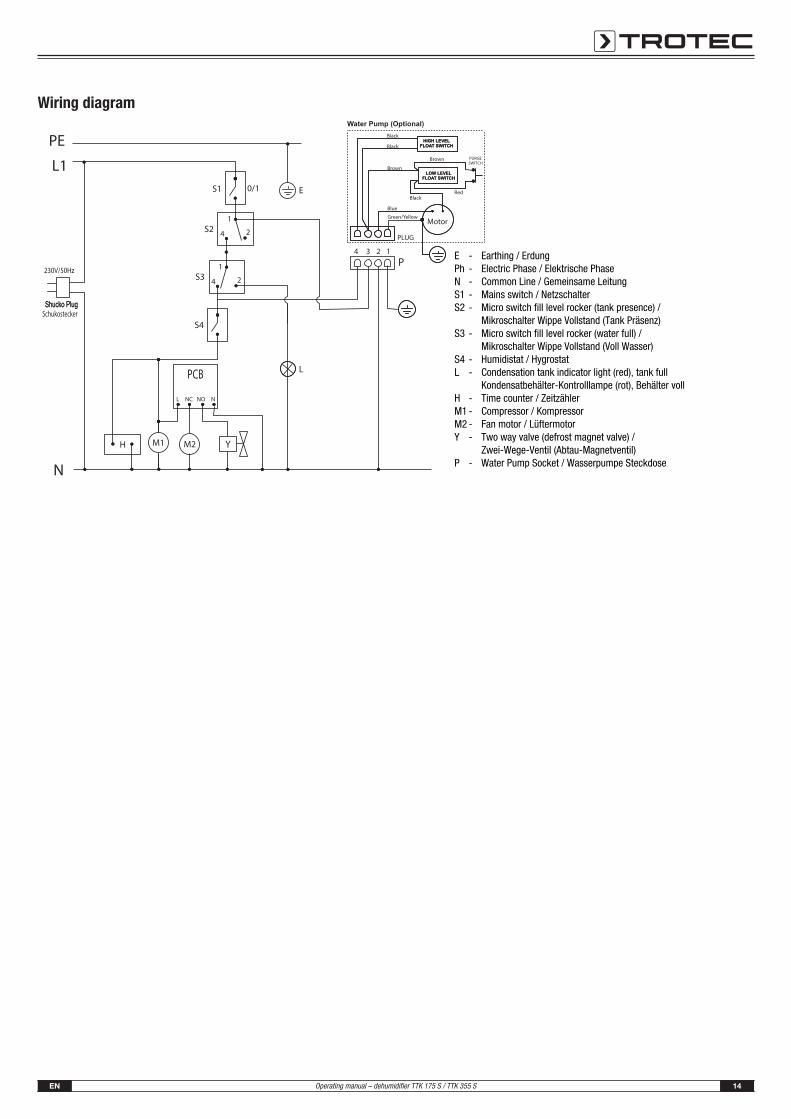
Wiring diagram
EPhNS1S2
S3
S4L
HM1M2Y
P
Earthing / ErdungElectric Phase / Elektrische PhaseCommon Line / Gemeinsame LeitungMains switch / NetzschalterMicro switch fill level rocker (tank presence) / Mikroschalter Wippe Vollstand (Tank Präsenz)Micro switch fill level rocker (water full) / Mikroschalter Wippe Vollstand (Voll Wasser)Humidistat / HygrostatCondensation tank indicator light (red), tank full Kondensatbehälter-Kontrolllampe (rot), Behälter vollTime counter / ZeitzählerCompressor / KompressorFan motor / LüftermotorTwo way valve (defrost magnet valve) / Zwei-Wege-Ventil (Abtau-Magnetventil)Water Pump Socket / Wasserpumpe Steckdose
-----
-
--
----
-

15 ENOperating manual – dehumidifier TTK 175 S / TTK 355 S
Exploded assembly drawing InfoThe position numbers of the spare parts differ fromthose describing the positions of other parts mentionedin this operating manual.
EN 16Operating manual – dehumidifier TTK 175 S / TTK 355 S
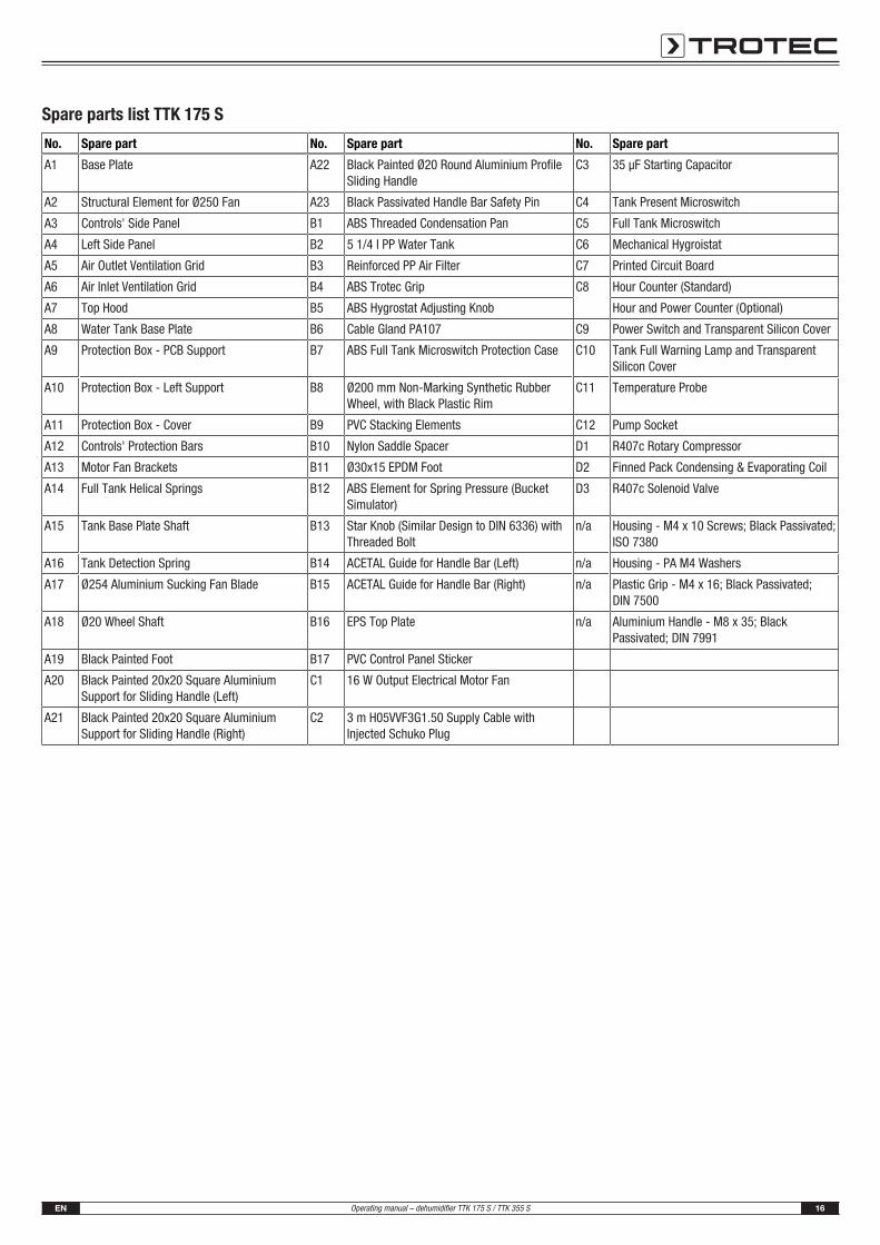
Spare parts list TTK 175 S
No. Spare part No. Spare part No. Spare part
A1 Base Plate A22 Black Painted Ø20 Round Aluminium ProfileSliding Handle
C3 35 μF Starting Capacitor
A2 Structural Element for Ø250 Fan A23 Black Passivated Handle Bar Safety Pin C4 Tank Present Microswitch
A3 Controls' Side Panel B1 ABS Threaded Condensation Pan C5 Full Tank Microswitch
A4 Left Side Panel B2 5 1/4 l PP Water Tank C6 Mechanical Hygroistat
A5 Air Outlet Ventilation Grid B3 Reinforced PP Air Filter C7 Printed Circuit Board
A6 Air Inlet Ventilation Grid B4 ABS Trotec Grip C8 Hour Counter (Standard)
A7 Top Hood B5 ABS Hygrostat Adjusting Knob Hour and Power Counter (Optional)
A8 Water Tank Base Plate B6 Cable Gland PA107 C9 Power Switch and Transparent Silicon Cover
A9 Protection Box - PCB Support B7 ABS Full Tank Microswitch Protection Case C10 Tank Full Warning Lamp and TransparentSilicon Cover
A10 Protection Box - Left Support B8 Ø200 mm Non-Marking Synthetic RubberWheel, with Black Plastic Rim
C11 Temperature Probe
A11 Protection Box - Cover B9 PVC Stacking Elements C12 Pump Socket
A12 Controls' Protection Bars B10 Nylon Saddle Spacer D1 R407c Rotary Compressor
A13 Motor Fan Brackets B11 Ø30x15 EPDM Foot D2 Finned Pack Condensing & Evaporating Coil
A14 Full Tank Helical Springs B12 ABS Element for Spring Pressure (BucketSimulator)
D3 R407c Solenoid Valve
A15 Tank Base Plate Shaft B13 Star Knob (Similar Design to DIN 6336) withThreaded Bolt
n/a Housing - M4 x 10 Screws; Black Passivated;ISO 7380
A16 Tank Detection Spring B14 ACETAL Guide for Handle Bar (Left) n/a Housing - PA M4 Washers
A17 Ø254 Aluminium Sucking Fan Blade B15 ACETAL Guide for Handle Bar (Right) n/a Plastic Grip - M4 x 16; Black Passivated; DIN 7500
A18 Ø20 Wheel Shaft B16 EPS Top Plate n/a Aluminium Handle - M8 x 35; BlackPassivated; DIN 7991
A19 Black Painted Foot B17 PVC Control Panel Sticker
A20 Black Painted 20x20 Square AluminiumSupport for Sliding Handle (Left)
C1 16 W Output Electrical Motor Fan
A21 Black Painted 20x20 Square AluminiumSupport for Sliding Handle (Right)
C2 3 m H05VVF3G1.50 Supply Cable withInjected Schuko Plug

17 ENOperating manual – dehumidifier TTK 175 S / TTK 355 S
Spare parts list TTK 355 S
No. Spare part No. Spare part No. Spare part
A1 Base Plate A22 Black Painted 20x20 Square AluminiumSupport for Sliding Handle (Right)
C1 25 W Output Electrical Motor Fan
A2 Structural Element for Ø300 Fan A23 Black Painted Ø20 Round Aluminium ProfileSliding Handle
C2 3 m H05VVF3G1.50 Supply Cable withInjected Schuko Plug
A4 Controls' Side Panel A24 Black Passivated Handle Bar Safety Pin C3 35 μF Starting Capacitor
A5 Left Side Panel B1 ABS Threaded Condensation Pan C4 Tank Present Microswitch
A6 Air Outlet Ventilation Grid B2 5 1/4 l PP Water Tank C5 Full Tank Microswitch
A7 Air Inlet Ventilation Grid B3 Reinforced PP Air Filter C6 Mechanical Hygrostat
A8 Top Hood B4 ABS Trotec Grip C7 Printed Circuit Board
A9 Water Tank Base Plate B5 ABS Hygrostat Adjusting Knob C8 Hour Counter (Standard)
A10 Protection Box - PCB Support B6 Cable Gland PA107 Hour + Power Counter (Optional)
A11 Protection Box - Left Support B7 ABS Full Tank Microswitch Protection Case C9 Power Switch + Transparent Silicon Cover
A12 Protection Box - Cover B8 Ø200 mm Non-Marking Synthetic RubberWheel, with Black Plastic Rim
C10 Tank Full Warning Lamp + TransparentSilicon Cover
A13 Controls' Protection Bars B9 PVC Stacking Elements C11 Temperature Probe
A14 Motor Fan Brackets B10 Nylon Saddle Spacer C12 Pump Socket
A15 Full Tank Helical Springs B11 Ø30x15 EPDM Foot D1 Rotary Compressor
A16 Tank Base Plate Shaft B12 ABS Element for Spring Pressure (BucketSimulator)
D2 Finned Pack Condensing & Evaporating Coil
A17 Tank Detection Spring B13 Star Knob (Similar Design to DIN 6336) withThreaded Bolt
D3 Solenoid Valve
A18 Ø300 Aluminium Sucking Fan Blade B14 ACETAL Guide for Handle Bar (Left) n/a Housing - M4 x 10 Screws; Black Passivated;ISO 7380
A19 Ø20 Wheel Shaft B15 ACETAL Guide for Handle Bar (Right) n/a Housing - PA M4 Washers
A20 Black Painted Foot B16 EPS Top Plate n/a Plastic Grip - M4 x 16; Black Passivated; DIN 7500
A21 Black Painted 20x20 Square AluminiumSupport for Sliding Handle (Left)
B17 PVC Control Panel Sticker n/a Aluminium Handle - M8 x 35; BlackPassivated; DIN 7991

EN 18Operating manual – dehumidifier TTK 175 S / TTK 355 S
Installing the condensate pump (optional)
InfoIf you use the device in combination with thecondensate pump via the TTKwic port and with theQube, the Qube should be switched on and ready foruse at all times to ensure the continuous operation ofthe pump.If the Qube's internal pump does not deliver, thecollected condensate in the Qube can flow back fromthe container through the suction hoses.
1.
2.
3.
4.
5.

19 ENOperating manual – dehumidifier TTK 175 S / TTK 355 S
6.
7.
Disposal
In the European Union, electronic equipment must not betreated as domestic waste, but must be disposed ofprofessionally in accordance with Directive 2012/19/EU of theEuropean Parliament and of the Council of 4 July 2012 on wasteelectrical and electronic equipment (WEEE). At the end of its life,please dispose of this device according to the valid legalrequirements.
The device uses an environmentally and ozone-neutral coolingagent (see Technical Data).
Dispose of the refrigerant appropriately and according to thenational regulations.
Declaration of conformityin accordance with the EC Low Voltage Directive 2006/95/ECand the EC Directive 2004/108/EC about electromagneticcompatibility.
Herewith, we declare that the device TTK 175 S / TTK 355 Swas developed, constructed and produced in compliance withthe named EC directives.
Applied standards:EN 60335-1:2012 + A1:2004 + A11:2004 + A12:2006 +A2:2006 + A13:2008 + A14:2010 + A15:2011EN 60335-2-40:2003 + A1:2006 + A2:2009 + A11:2004 +A12:2005EN 61000-3-2:2006 + A1:2009 + A2:2009EN 61000-3-3:2008EN 55014-1:2006 + A1:2009 + A2:2011EN 55014-2:1997 + A1:2001 + A2:2008
The marking is found on the rear of the device.
Manufacturer:
Trotec GmbH & Co. KG
Grebbener Straße 7
D-52525 Heinsberg
Phone: +49 2452 962-400
Fax: +49 2452 962-200
E-mail: [email protected]
Heinsberg, 19.04.2012
Detlef von der Lieck
Managing Director


Trotec GmbH & Co. KG
Grebbener Str. 7D-52525 Heinsberg
+49 2452 962-400+49 2452 962-200


![Meaco 12L-AH Dehumidifier › pdfs › Meaco_12AH_Instruction... · 4 [EN] 1. GENERAL ADVICE Before putting your dehumidifier into operation for the first time, the instruction manual](https://img.pdfslide.us/doc/110x75/5f0e4f877e708231d43e9fa4/meaco-12l-ah-dehumidifier-a-pdfs-a-meaco12ahinstruction-4-en-1-general.jpg)

![Meaco DD8L Zambezi Dehumidifier - Climatronics · Meaco DD8L Zambezi Dehumidifier Thank you for choosing Meaco, we really do appreciate it INSTRUCTION MANUAL [EN] DD8L Zambezi](https://img.pdfslide.us/doc/110x75/5b5b40477f8b9a01748da729/meaco-dd8l-zambezi-dehumidifier-climatronics-meaco-dd8l-zambezi-dehumidifier.jpg)