Embed Size (px)
Citation preview
Emerging Subsea Networks
Copyright © SubOptic2016 Page 1 of 8
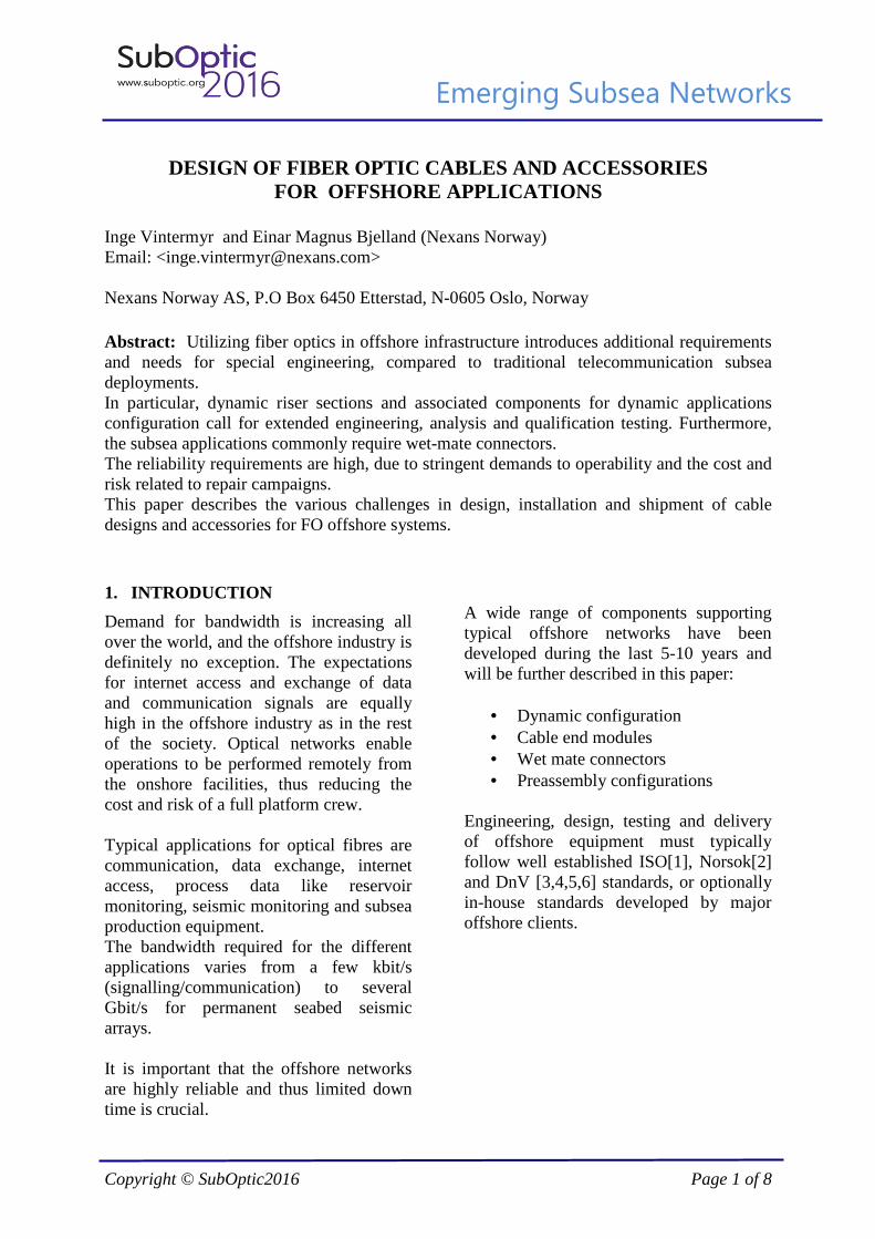
DESIGN OF FIBER OPTIC CABLES AND ACCESSORIES
FOR OFFSHORE APPLICATIONS Inge Vintermyr and Einar Magnus Bjelland (Nexans Norway) Email: <[email protected]> Nexans Norway AS, P.O Box 6450 Etterstad, N-0605 Oslo, Norway Abstract: Utilizing fiber optics in offshore infrastructure introduces additional requirements and needs for special engineering, compared to traditional telecommunication subsea deployments. In particular, dynamic riser sections and associated components for dynamic applications configuration call for extended engineering, analysis and qualification testing. Furthermore, the subsea applications commonly require wet-mate connectors. The reliability requirements are high, due to stringent demands to operability and the cost and risk related to repair campaigns. This paper describes the various challenges in design, installation and shipment of cable designs and accessories for FO offshore systems. 1. INTRODUCTION
Demand for bandwidth is increasing all over the world, and the offshore industry is definitely no exception. The expectations for internet access and exchange of data and communication signals are equally high in the offshore industry as in the rest of the society. Optical networks enable operations to be performed remotely from the onshore facilities, thus reducing the cost and risk of a full platform crew. Typical applications for optical fibres are communication, data exchange, internet access, process data like reservoir monitoring, seismic monitoring and subsea production equipment. The bandwidth required for the different applications varies from a few kbit/s (signalling/communication) to several Gbit/s for permanent seabed seismic arrays. It is important that the offshore networks are highly reliable and thus limited down time is crucial.
A wide range of components supporting typical offshore networks have been developed during the last 5-10 years and will be further described in this paper:
• Dynamic configuration • Cable end modules • Wet mate connectors • Preassembly configurations
Engineering, design, testing and delivery of offshore equipment must typically follow well established ISO[1], Norsok[2] and DnV [3,4,5,6] standards, or optionally in-house standards developed by major offshore clients.
Emerging Subsea Networks
Copyright © SubOptic2016 Page 2 of 8
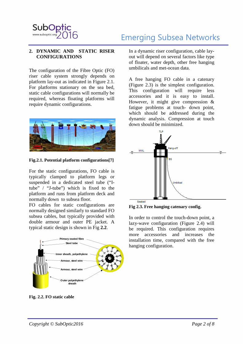
2. DYNAMIC AND STATIC RISER CONFIGURATIONS
The configuration of the Fibre Optic (FO) riser cable system strongly depends on platform lay-out as indicated in Figure 2.1. For platforms stationary on the sea bed, static cable configurations will normally be required, whereas floating platforms will require dynamic configurations.
Fig.2.1. Potential platform configurations[7] For the static configurations, FO cable is typically clamped to platform legs or suspended in a dedicated steel tube (“I-tube” / “J-tube”) which is fixed to the platform and runs from platform deck and normally down to subsea floor. FO cables for static configurations are normally designed similarly to standard FO subsea cables, but typically provided with double armour and outer PE jacket. A typical static design is shown in Fig 2.2.
Primary coated fibre
Steel tube
Inner sheath, polyethylene
Armour, steel wire
Armour, steel wire
Outer polyethylenesheath
Fig. 2.2. FO static cable
In a dynamic riser configuration, cable lay-out will depend on several factors like type of floater, water depth, other free hanging umbilicals and met-ocean data. A free hanging FO cable in a catenary (Figure 2.3) is the simplest configuration. This configuration will require less accessories and it is easy to install. However, it might give compression & fatigue problems at touch- down point, which should be addressed during the dynamic analysis. Compression at touch down should be minimized.
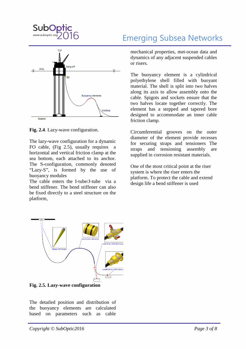
Fig 2.3. Free hanging catenary config. In order to control the touch-down point, a lazy-wave configuration (Figure 2.4) will be required. This configuration requires more accessories and increases the installation time, compared with the free hanging configuration.
Emerging Subsea Networks
Copyright © SubOptic2016 Page 3 of 8
Fig. 2.4. Lazy-wave configuration. The lazy-wave configuration for a dynamic FO cable, (Fig 2.5), usually requires a horizontal and vertical friction clamp at the sea bottom, each attached to its anchor. The S-configuration, commonly denoted “Lazy-S”, is formed by the use of buoyancy modules The cable enters the I-tube/J-tube via a bend stiffener. The bend stiffener can also be fixed directly to a steel structure on the platform,
Fig. 2.5. Lazy-wave configuration The detailed position and distribution of the buoyancy elements are calculated based on parameters such as cable
mechanical properties, met-ocean data and dynamics of any adjacent suspended cables or risers. The buoyancy element is a cylindrical polyethylene shell filled with buoyant material. The shell is split into two halves along its axis to allow assembly onto the cable. Spigots and sockets ensure that the two halves locate together correctly. The element has a stepped and tapered bore designed to accommodate an inner cable friction clamp. Circumferential grooves on the outer diameter of the element provide recesses for securing straps and tensioners The straps and tensioning assembly are supplied in corrosion resistant materials. One of the most critical point at the riser system is where the riser enters the platform. To protect the cable and extend design life a bend stiffener is used
Emerging Subsea Networks
Copyright © SubOptic2016 Page 4 of 8
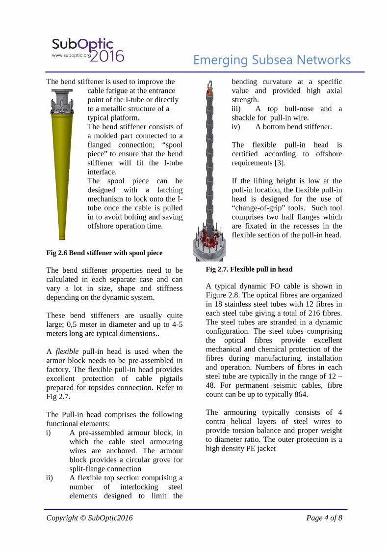
The bend stiffener is used to improve the cable fatigue at the entrance point of the I-tube or directly to a metallic structure of a typical platform. The bend stiffener consists of a molded part connected to a flanged connection; “spool piece” to ensure that the bend stiffener will fit the I-tube interface. The spool piece can be designed with a latching mechanism to lock onto the I-tube once the cable is pulled in to avoid bolting and saving offshore operation time.
Fig 2.6 Bend stiffener with spool piece The bend stiffener properties need to be calculated in each separate case and can vary a lot in size, shape and stiffness depending on the dynamic system. These bend stiffeners are usually quite large; 0,5 meter in diameter and up to 4-5 meters long are typical dimensions.. A flexible pull-in head is used when the armor block needs to be pre-assembled in factory. The flexible pull-in head provides excellent protection of cable pigtails prepared for topsides connection. Refer to Fig 2.7. The Pull-in head comprises the following functional elements: i) A pre-assembled armour block, in
which the cable steel armouring wires are anchored. The armour block provides a circular grove for split-flange connection
ii) A flexible top section comprising a number of interlocking steel elements designed to limit the
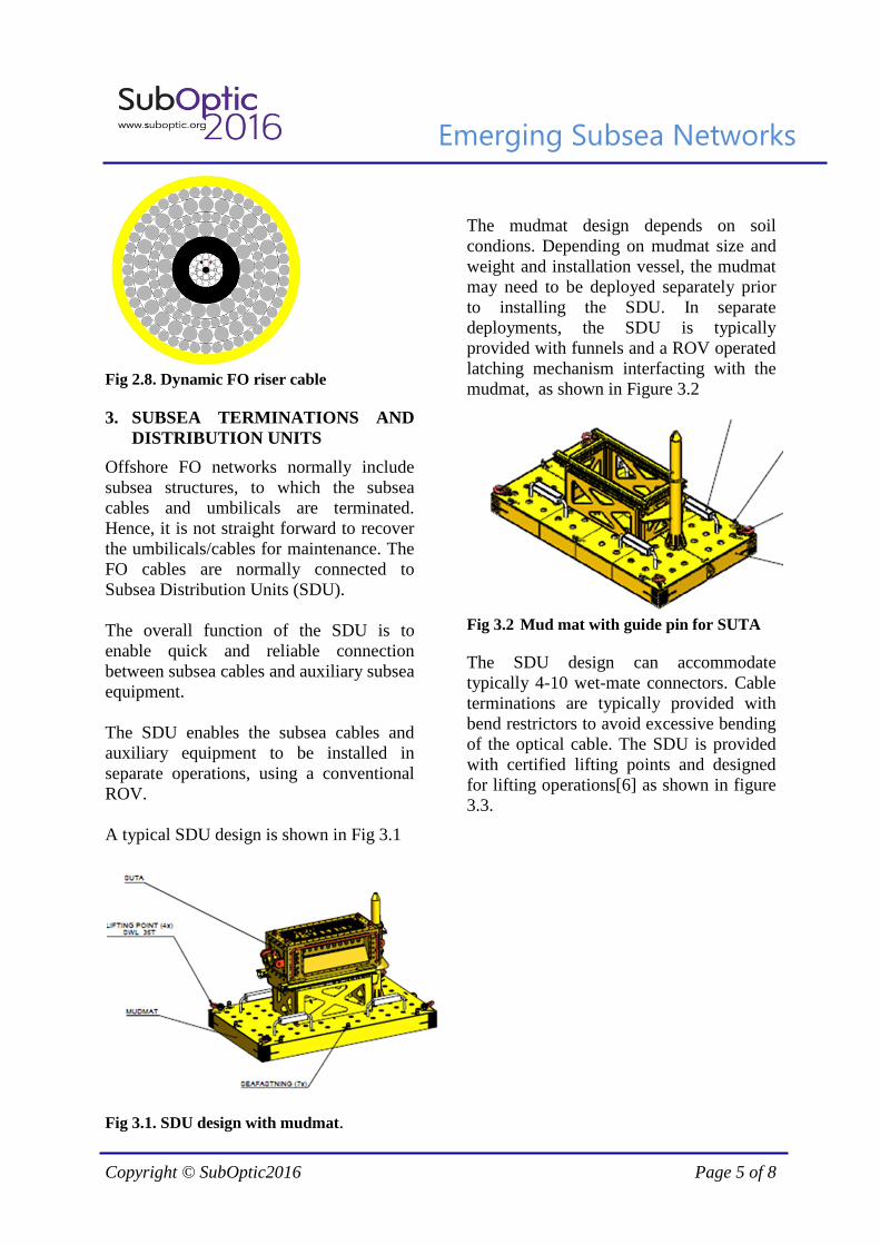
bending curvature at a specific value and provided high axial strength. iii) A top bull-nose and a shackle for pull-in wire. iv) A bottom bend stiffener.
The flexible pull-in head is certified according to offshore requirements [3]. If the lifting height is low at the pull-in location, the flexible pull-in head is designed for the use of “change-of-grip” tools. Such tool comprises two half flanges which are fixated in the recesses in the flexible section of the pull-in head.
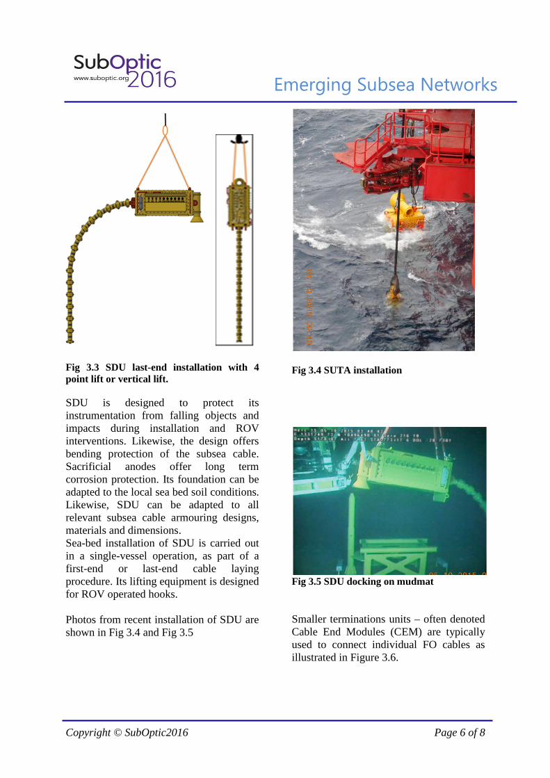
Fig 2.7. Flexible pull in head A typical dynamic FO cable is shown in Figure 2.8. The optical fibres are organized in 18 stainless steel tubes with 12 fibres in each steel tube giving a total of 216 fibres. The steel tubes are stranded in a dynamic configuration. The steel tubes comprising the optical fibres provide excellent mechanical and chemical protection of the fibres during manufacturing, installation and operation. Numbers of fibres in each steel tube are typically in the range of 12 – 48. For permanent seismic cables, fibre count can be up to typically 864. The armouring typically consists of 4 contra helical layers of steel wires to provide torsion balance and proper weight to diameter ratio. The outer protection is a high density PE jacket
Emerging Subsea Networks
Copyright © SubOptic2016 Page 5 of 8
Fig 2.8. Dynamic FO riser cable 3. SUBSEA TERMINATIONS AND
DISTRIBUTION UNITS
Offshore FO networks normally include subsea structures, to which the subsea cables and umbilicals are terminated. Hence, it is not straight forward to recover the umbilicals/cables for maintenance. The FO cables are normally connected to Subsea Distribution Units (SDU). The overall function of the SDU is to enable quick and reliable connection between subsea cables and auxiliary subsea equipment. The SDU enables the subsea cables and auxiliary equipment to be installed in separate operations, using a conventional ROV. A typical SDU design is shown in Fig 3.1
Fig 3.1. SDU design with mudmat.
The mudmat design depends on soil condions. Depending on mudmat size and weight and installation vessel, the mudmat may need to be deployed separately prior to installing the SDU. In separate deployments, the SDU is typically provided with funnels and a ROV operated latching mechanism interfacting with the mudmat, as shown in Figure 3.2
Fig 3.2 Mud mat with guide pin for SUTA The SDU design can accommodate typically 4-10 wet-mate connectors. Cable terminations are typically provided with bend restrictors to avoid excessive bending of the optical cable. The SDU is provided with certified lifting points and designed for lifting operations[6] as shown in figure 3.3.
Emerging Subsea Networks
Copyright © SubOptic2016 Page 6 of 8
Fig 3.3 SDU last-end installation with 4 point lift or vertical lift. SDU is designed to protect its instrumentation from falling objects and impacts during installation and ROV interventions. Likewise, the design offers bending protection of the subsea cable. Sacrificial anodes offer long term corrosion protection. Its foundation can be adapted to the local sea bed soil conditions. Likewise, SDU can be adapted to all relevant subsea cable armouring designs, materials and dimensions. Sea-bed installation of SDU is carried out in a single-vessel operation, as part of a first-end or last-end cable laying procedure. Its lifting equipment is designed for ROV operated hooks. Photos from recent installation of SDU are shown in Fig 3.4 and Fig 3.5
Fig 3.4 SUTA installation
Fig 3.5 SDU docking on mudmat Smaller terminations units – often denoted Cable End Modules (CEM) are typically used to connect individual FO cables as illustrated in Figure 3.6.
Emerging Subsea Networks
Copyright © SubOptic2016 Page 7 of 8
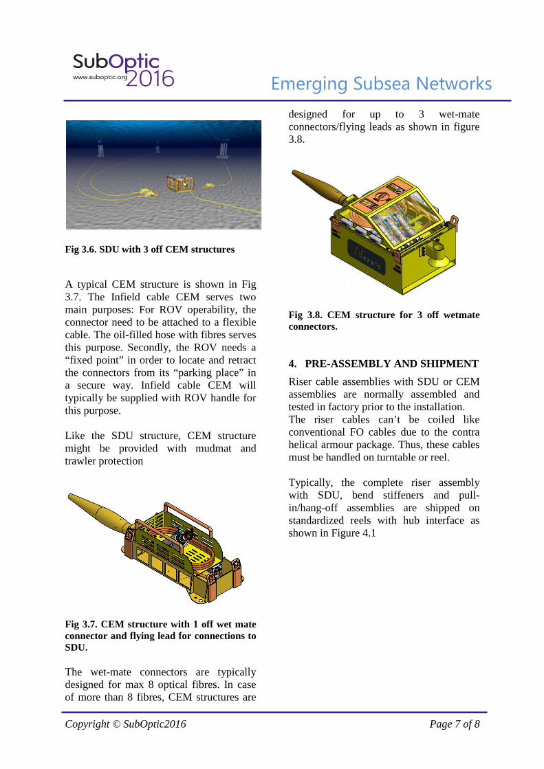
Fig 3.6. SDU with 3 off CEM structures A typical CEM structure is shown in Fig 3.7. The Infield cable CEM serves two main purposes: For ROV operability, the connector need to be attached to a flexible cable. The oil-filled hose with fibres serves this purpose. Secondly, the ROV needs a “fixed point” in order to locate and retract the connectors from its “parking place” in a secure way. Infield cable CEM will typically be supplied with ROV handle for this purpose. Like the SDU structure, CEM structure might be provided with mudmat and trawler protection
Fig 3.7. CEM structure with 1 off wet mate connector and flying lead for connections to SDU. The wet-mate connectors are typically designed for max 8 optical fibres. In case of more than 8 fibres, CEM structures are
designed for up to 3 wet-mate connectors/flying leads as shown in figure 3.8.
Fig 3.8. CEM structure for 3 off wetmate connectors. 4. PRE-ASSEMBLY AND SHIPMENT
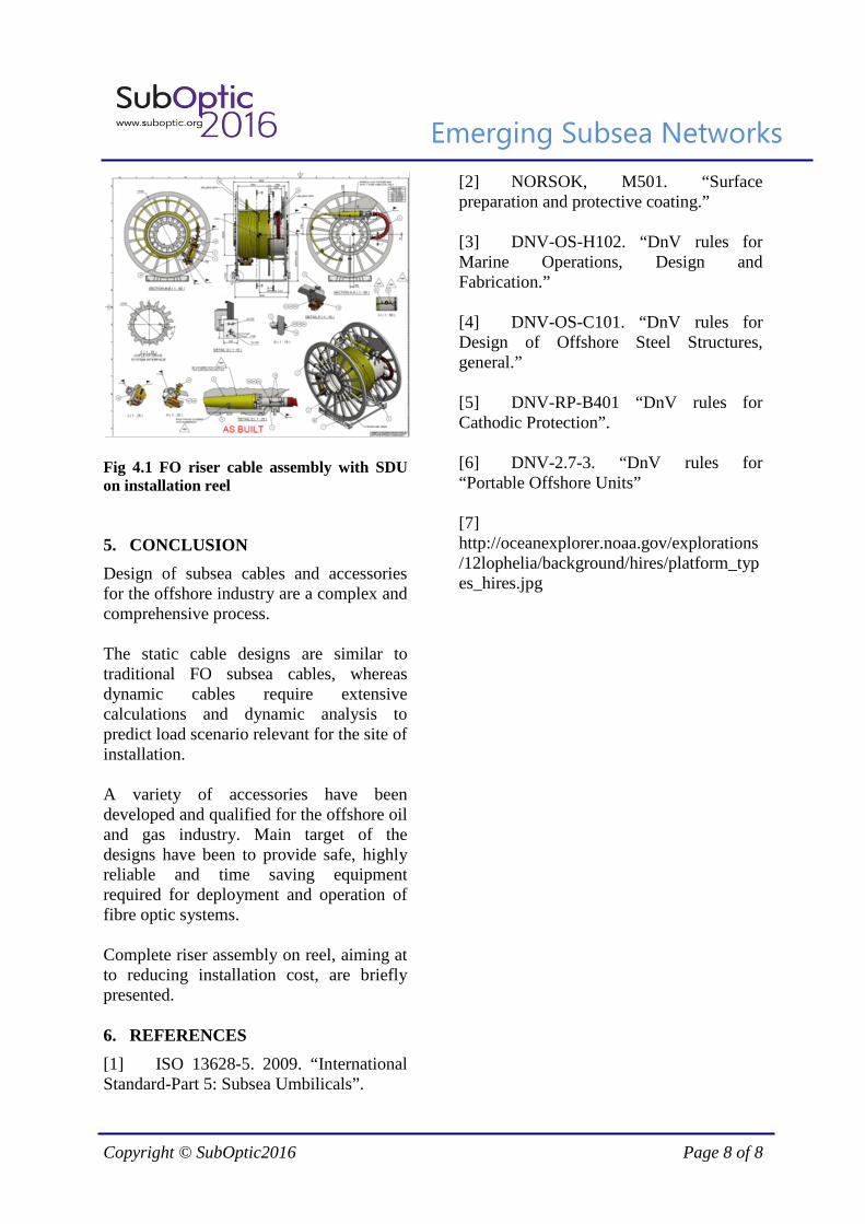
Riser cable assemblies with SDU or CEM assemblies are normally assembled and tested in factory prior to the installation. The riser cables can’t be coiled like conventional FO cables due to the contra helical armour package. Thus, these cables must be handled on turntable or reel. Typically, the complete riser assembly with SDU, bend stiffeners and pull-in/hang-off assemblies are shipped on standardized reels with hub interface as shown in Figure 4.1
Emerging Subsea Networks
Copyright © SubOptic2016 Page 8 of 8
Fig 4.1 FO riser cable assembly with SDU on installation reel 5. CONCLUSION
Design of subsea cables and accessories for the offshore industry are a complex and comprehensive process. The static cable designs are similar to traditional FO subsea cables, whereas dynamic cables require extensive calculations and dynamic analysis to predict load scenario relevant for the site of installation. A variety of accessories have been developed and qualified for the offshore oil and gas industry. Main target of the designs have been to provide safe, highly reliable and time saving equipment required for deployment and operation of fibre optic systems. Complete riser assembly on reel, aiming at to reducing installation cost, are briefly presented. 6. REFERENCES
[1] ISO 13628-5. 2009. “International Standard-Part 5: Subsea Umbilicals”.
[2] NORSOK, M501. “Surface preparation and protective coating.” [3] DNV-OS-H102. “DnV rules for Marine Operations, Design and Fabrication.” [4] DNV-OS-C101. “DnV rules for Design of Offshore Steel Structures, general.” [5] DNV-RP-B401 “DnV rules for Cathodic Protection”. [6] DNV-2.7-3. “DnV rules for “Portable Offshore Units” [7] http://oceanexplorer.noaa.gov/explorations/12lophelia/background/hires/platform_types_hires.jpg