Embed Size (px)
Citation preview
Rethinking Subsea Boosting for Optimized Subsea Field DevelopmentZahid [email protected]
23rd February 2017
Page footer text | 2
Outline
1. Introduction – Subsea Boosting
2. Boosting Technology ‐ Pumps
3. Value Drivers
4. Re‐thinking Subsea Boosting
Page footer text | 3
Introduction – What is Subsea Boosting and its applications
Page footer text | 4
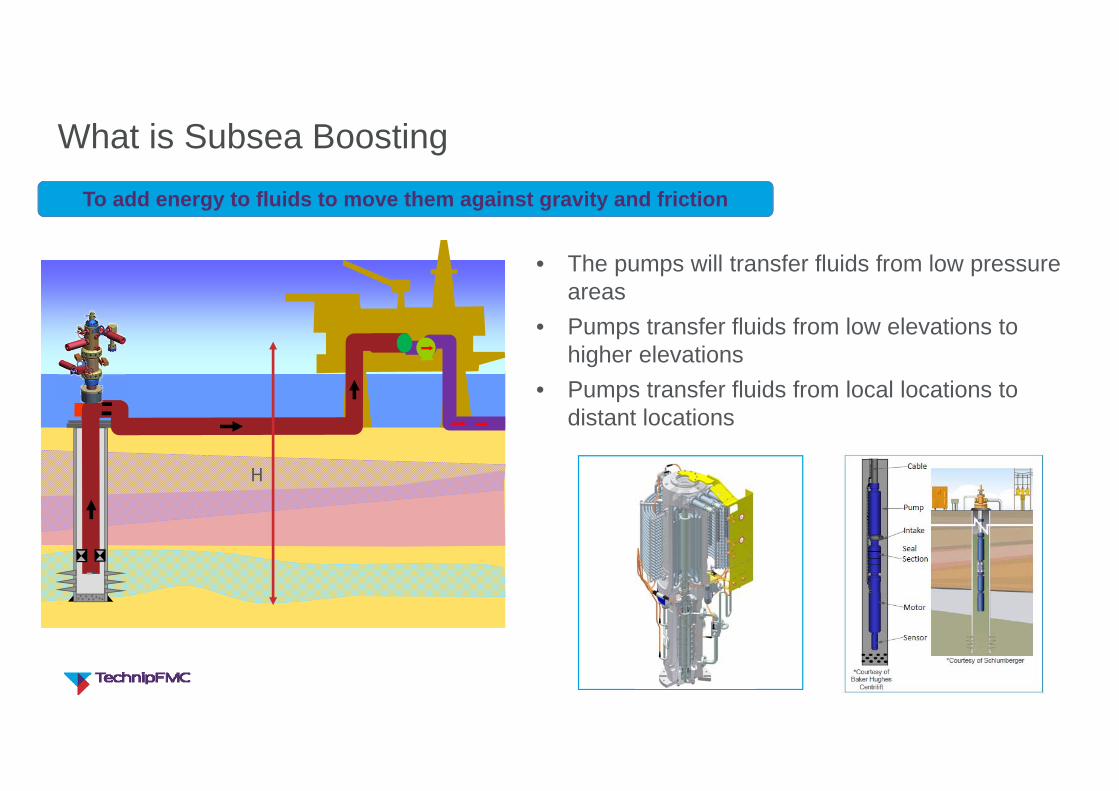
What is Subsea Boosting
• The pumps will transfer fluids from low pressure areas
• Pumps transfer fluids from low elevations to higher elevations
• Pumps transfer fluids from local locations to distant locations
H
To add energy to fluids to move them against gravity and friction
Page footer text | 5
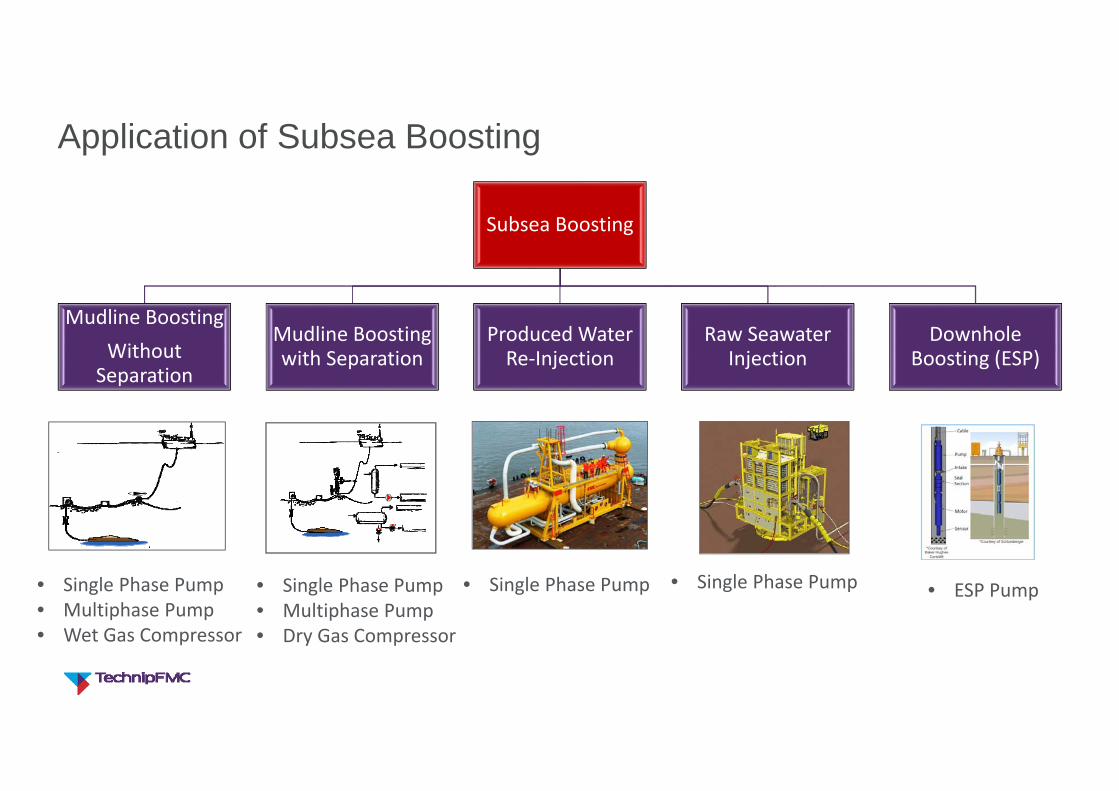
Application of Subsea Boosting
Subsea Boosting
Mudline BoostingWithout Separation
Mudline Boosting with Separation
Produced Water Re‐Injection
Raw Seawater Injection
Downhole Boosting (ESP)
• Single Phase Pump• Multiphase Pump• Wet Gas Compressor
• Single Phase Pump• Single Phase Pump• Single Phase Pump• Multiphase Pump• Dry Gas Compressor
• ESP Pump
Page footer text | 6
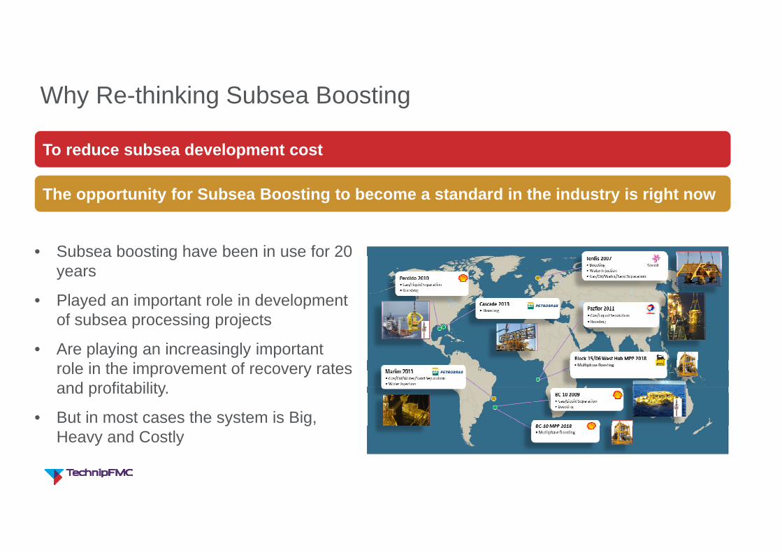
Why Re-thinking Subsea Boosting
• Subsea boosting have been in use for 20 years
• Played an important role in development of subsea processing projects
• Are playing an increasingly important role in the improvement of recovery rates and profitability.
• But in most cases the system is Big, Heavy and Costly
To reduce subsea development cost
The opportunity for Subsea Boosting to become a standard in the industry is right now

Page footer text | 7
Boosting Technology - Pumps
Page footer text | 8
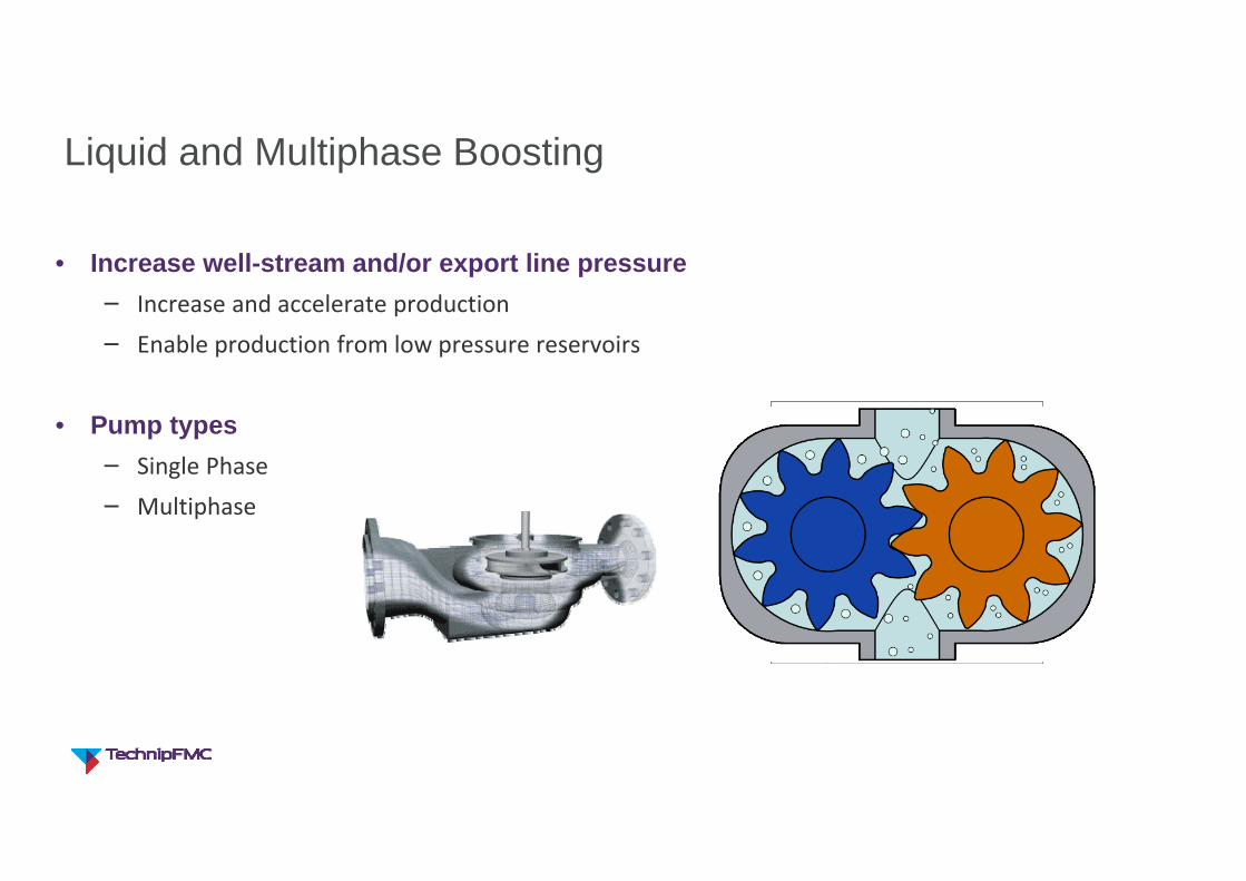
Liquid and Multiphase Boosting
• Increase well-stream and/or export line pressure− Increase and accelerate production− Enable production from low pressure reservoirs
• Pump types− Single Phase− Multiphase
Page footer text | 9
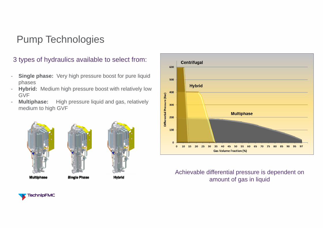
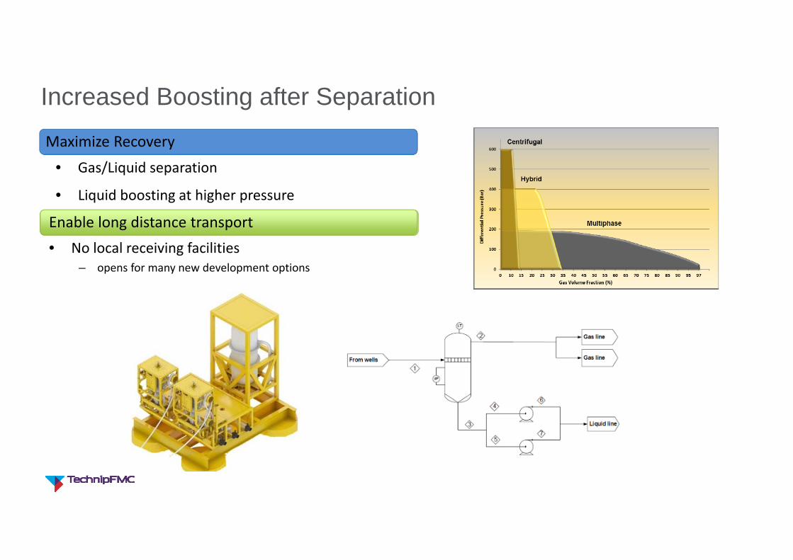
Pump Technologies
3 types of hydraulics available to select from:
- Single phase: Very high pressure boost for pure liquid phases
- Hybrid: Medium high pressure boost with relatively low GVF
- Multiphase: High pressure liquid and gas, relatively medium to high GVF
Achievable differential pressure is dependent on amount of gas in liquid
Page footer text | 10
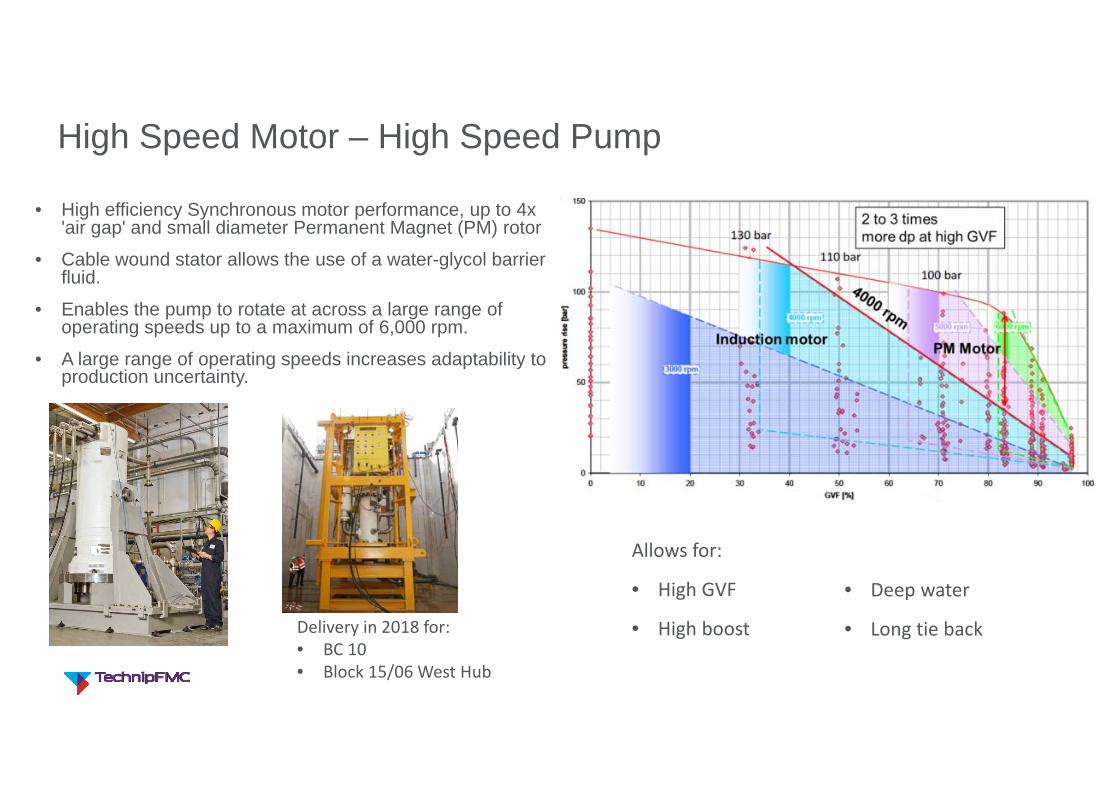
High Speed Motor – High Speed Pump
• High efficiency Synchronous motor performance, up to 4x 'air gap' and small diameter Permanent Magnet (PM) rotor
• Cable wound stator allows the use of a water-glycol barrier fluid.
• Enables the pump to rotate at across a large range of operating speeds up to a maximum of 6,000 rpm.
• A large range of operating speeds increases adaptability to production uncertainty.
Allows for:
• High GVF
• High boost
• Deep water
• Long tie back Delivery in 2018 for:• BC 10• Block 15/06 West Hub
Page footer text | 11
Subsea Boosting – Value Drivers
Page footer text | 12
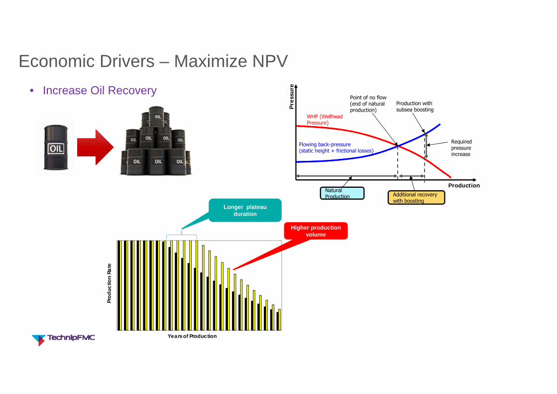
Economic Drivers – Maximize NPV• Increase Oil Recovery
Production
Point of no flow(end of natural production)
WHP (Wellhead Pressure)
Flowing back-pressure(static height + frictional losses)
Pre
ssur
e
Natural Production
Production with subsea boosting
Additional recovery with boosting
Required pressure increase
Prod
uctio
n Ra
te
Years of Production
Longer plateau duration
Higher production volume
Page footer text | 13
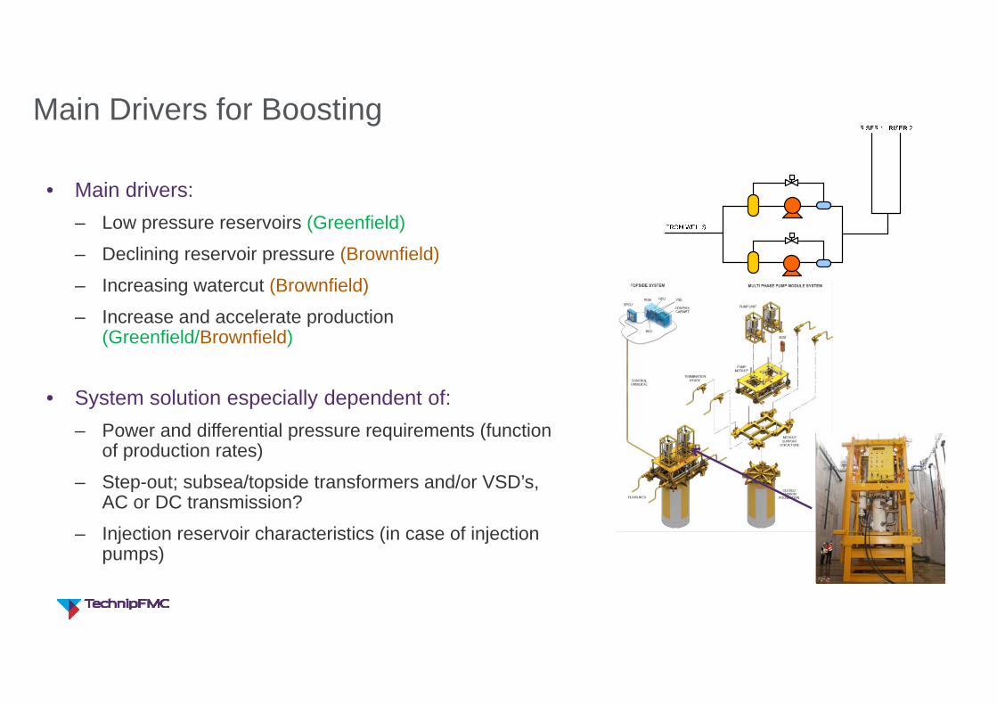
Main Drivers for Boosting
• Main drivers:– Low pressure reservoirs (Greenfield)
– Declining reservoir pressure (Brownfield)
– Increasing watercut (Brownfield)
– Increase and accelerate production (Greenfield/Brownfield)
• System solution especially dependent of:– Power and differential pressure requirements (function
of production rates)
– Step-out; subsea/topside transformers and/or VSD’s, AC or DC transmission?
– Injection reservoir characteristics (in case of injection pumps)
Page footer text | 14
Rethinking Subsea Boosting System
Page footer text | 15
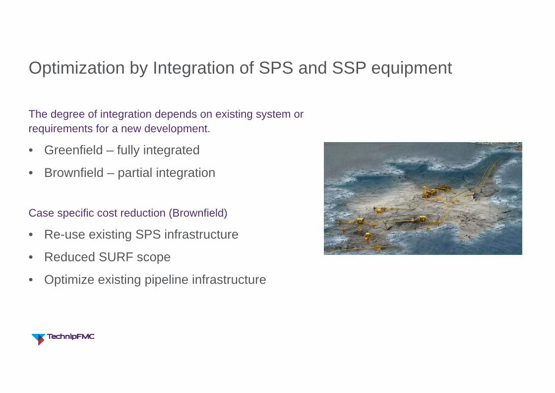
Optimization by Integration of SPS and SSP equipment
The degree of integration depends on existing system or requirements for a new development.
• Greenfield – fully integrated
• Brownfield – partial integration
Case specific cost reduction (Brownfield)
• Re-use existing SPS infrastructure
• Reduced SURF scope
• Optimize existing pipeline infrastructure
Page footer text | 16
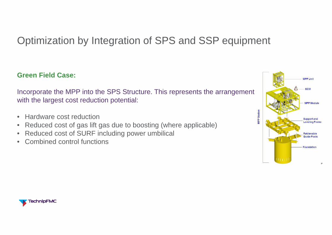
Optimization by Integration of SPS and SSP equipment
Green Field Case:
Incorporate the MPP into the SPS Structure. This represents the arrangement with the largest cost reduction potential:
• Hardware cost reduction• Reduced cost of gas lift gas due to boosting (where applicable)• Reduced cost of SURF including power umbilical• Combined control functions
Page footer text | 17
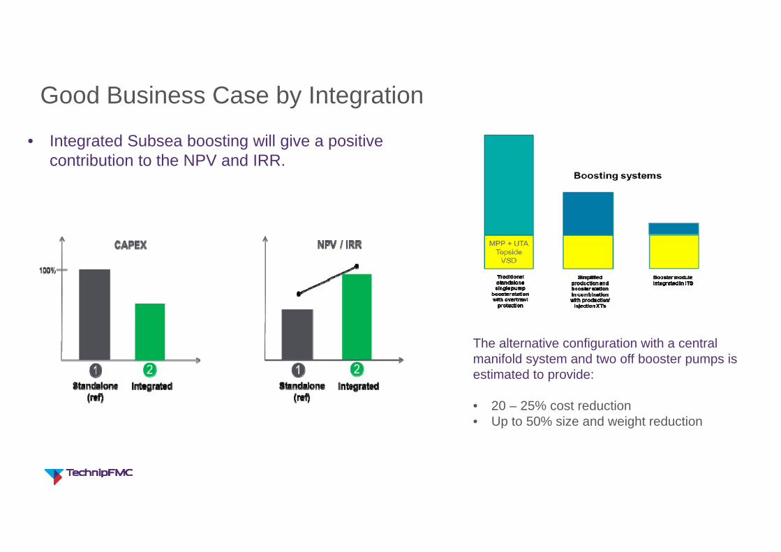
Good Business Case by Integration
• Integrated Subsea boosting will give a positive contribution to the NPV and IRR.
The alternative configuration with a central manifold system and two off booster pumps is estimated to provide:
• 20 – 25% cost reduction• Up to 50% size and weight reduction
Page footer text | 18
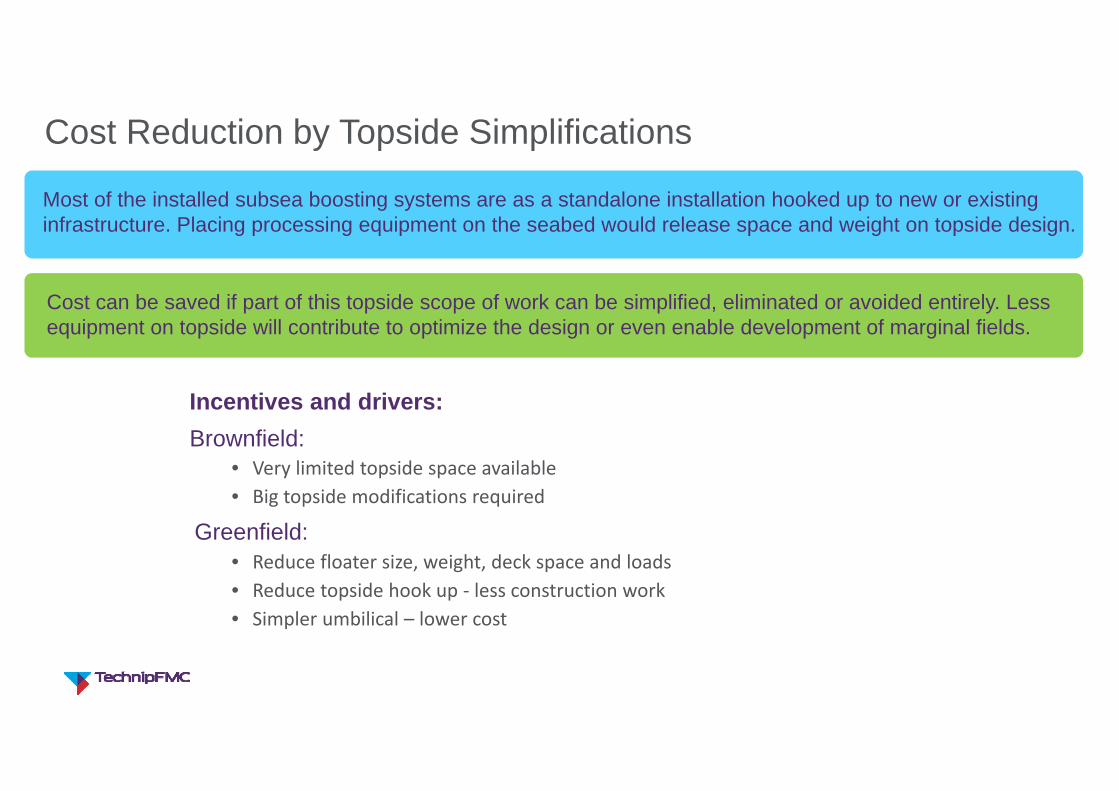
Cost Reduction by Topside Simplifications
Incentives and drivers:Brownfield:
• Very limited topside space available• Big topside modifications required
Greenfield:• Reduce floater size, weight, deck space and loads• Reduce topside hook up ‐ less construction work• Simpler umbilical – lower cost
Most of the installed subsea boosting systems are as a standalone installation hooked up to new or existing infrastructure. Placing processing equipment on the seabed would release space and weight on topside design.
Cost can be saved if part of this topside scope of work can be simplified, eliminated or avoided entirely. Less equipment on topside will contribute to optimize the design or even enable development of marginal fields.
Page footer text | 19
Increased Boosting after Separation
Maximize Recovery
• Gas/Liquid separation
• Liquid boosting at higher pressure
Enable long distance transport• No local receiving facilities
– opens for many new development options
Page footer text | 20
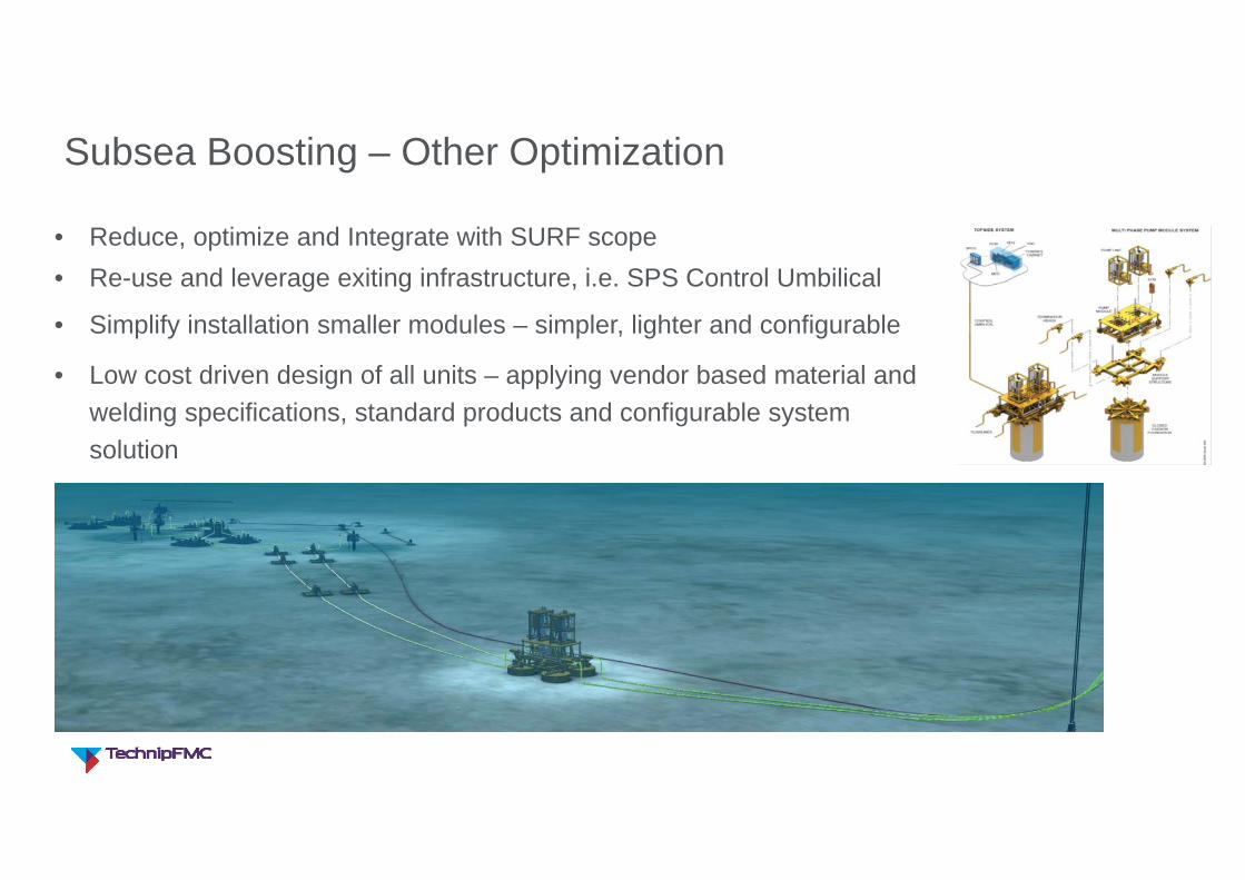
• Reduce, optimize and Integrate with SURF scope • Re-use and leverage exiting infrastructure, i.e. SPS Control Umbilical
• Simplify installation smaller modules – simpler, lighter and configurable
• Low cost driven design of all units – applying vendor based material and welding specifications, standard products and configurable system solution
Subsea Boosting – Other Optimization
Page footer text | 21
Summary and Conclusions
Page footer text | 22
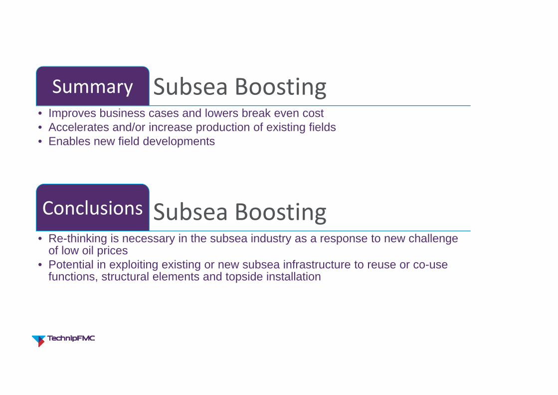
Subsea BoostingSummary• Improves business cases and lowers break even cost• Accelerates and/or increase production of existing fields• Enables new field developments
Subsea BoostingConclusions• Re-thinking is necessary in the subsea industry as a response to new challenge
of low oil prices• Potential in exploiting existing or new subsea infrastructure to reuse or co-use
functions, structural elements and topside installation
Page footer text | 23
Thank You