Embed Size (px)
Citation preview

2ELECTRODEPOSITION OF COPPER
JACK W. DINI AND DEXTER D. SNYDER1
Copper is the most common metal plated, exclusive of
continuous strip plating and nickel [1]. The major uses of
electroplated copper are plating on plastics, printed wiring
boards, zinc die castings, automotive bumpers, rotogravure
rolls, electrorefining, and electroforming [2]. Electroplated
copper is playing a major role in the change from aluminum
to copper in semiconductor interconnect technology. This
materials change was heralded as a “major breakthrough” in
The New York Times (September 22, 1997) and a “dazzling
technical advance” by Time magazine (October 10, 1997)
[2a]. It signals one of themost important changes inmaterials
that the semiconductor industry has experienced since its
creation [2b]. Copper is electrodeposited for numerous en-
gineering and decorative applications requiring a wide range
of mechanical and physical properties. The range extends
from properties superior to full-hard wrought copper to
properties equivalent to annealed pure copper [3].
Copper is an excellent choice for an underplate, since it
often covers minor imperfections in the base metal. It is
relatively inert in most plating solutions of other common
metals; it has a very high plating efficiency, resulting in
excellent coverage even on difficult-to-plate parts; and lastly,
it is highly conductive, making it an excellent coating for
printed wiring boards or as a coating on steel wire used to
conduct electricity [1].
Copper deposits also act as thermal expansion barriers
by absorbing the stress produced when metals with different
thermal expansion coefficients undergo temperature
changes, and this is particularly helpful with plastic sub-
strates. The leveling and brightness properties of copper
deposits can be further enhanced by buffing, and since copper
is much softer than steel or nickel, it is easy and relatively
inexpensive to buff [4].
Of the plating systems that have been studied, only
relatively few have revealed a stage of commercial impor-
tance for electrodeposition of copper. These are the alkaline
cyanide and pyrophosphate complex ion systems and the
acid sulfate and fluoborate simple ion systems. Other types
of solutions have been too unstable or lacking in good
deposit characteristics over sufficiently wide current density
ranges [5]. In recent years some alkaline noncyanide systems
have been developed for replacing cyanide.
The areas of application of the various copper plating
solutions overlap somewhat, but each has its fairly well-
defined area of usefulness. Clearly, the most heavily used are
the acid copper sulfate solutions. Open literature publications
and patents for sulfate solutions since the 1974 edition of this
book in [6] far outnumber those of all the other solutions
combined. Deposits produced in cyanide solutions are typ-
ically thin (<12.5 mm) and are used as an undercoating for
nickel and chromium, as a heat treatment slop-off for selec-
tivehardeningof ferrous parts, or as an intermediate step prior
to additional plating. For example, a copper cyanide deposit
is typically a key part of the activation cycle for preparing
aluminum, beryllium, and zinc die castings for plating.
Copper deposits from cyanide solutions are not generally
suitable for deposition of relatively thick deposits for elec-
troforming and similar applications. Cyanide solutions are
finding less and less favor because of their toxicity and waste
treatment problems and are being replaced by noncyanide
solutions. Pyrophosphate solutions, once used heavily for
plating through holes on printed wiring boards, have been
almost completely replaced by high-throw acid sulfate solu-
tions. Fluoborate solutions have been advertised for many
years as having the capability to deposit copper at very high
Modern Electroplating, Fifth Edition Edited by Mordechay Schlesinger and Milan PaunovicCopyright � 2010 John Wiley & Sons, Inc.
1 Dexter D. Snyder, Part F.
33

current densities. However, present commercial usage of this
type of solution is minimal simply because other solutions
such as those with sulfate ions can do the same job and are
less expensive, easier to control, and less susceptible to
impurities. The chemical cost of acid fluoborate electrolyte
is approximately twice that of acid sulfate per gallon, which
is one strong reason why fluoborate copper has not gained
a significant share of the through-hole plating market [7].
Continuous copper plating from fluoborate solutions on
electroless coated plastic circuits has been reported [8].
PART A ACID COPPER*
2.1 HISTORY AND DEVELOPMENT
Acid copper deposition was referred to as early as 1810 [9].
In 1831 Bessemer [10] copper plated steel castings of frogs,
insects, and plants by immersion in copper sulfate solution
on a zinc tray. In 1836 the Daniel cell was first used for
electrodepositing copper [11] and a technical report was
published by De la Rue [12]. In 1839 Jacobi made Russian
bank notes using copper-plated electrotypes, and in 1840 he
received the first patent for making electrotypes [13]. Smee
discussed commercial copper plating processes in 1843 [9].
During the next 70 years, progress was directed principally
toward developing specific applications for acid copper
electrodeposition. Most of the efforts dealt with Cu2þ
sulfate–sulfuric acid solutions, but oxalate [14], nitrate [15],
acetate [15], fluosilicate [16, 17], and Culþ chloride [16]
solutions were also investigated.
In more recent times the following solutions have been
evaluated: sulfate–oxalate–boric acid [18], sulfate–
oxalate [19, 20], Cu1þ chloride [21], Cu1þ chloride–sodium
thiosulfate [22], benzene disulfonic acid [23], Cu1þ iodide
and bromide [24], iodide and chloride [25], fluoborate
[26, 27], alkane sulfonic acid [28, 29], sulfamic acid [30, 31],
Cu2þ formate with ammonium salts [32], phosphate–
sulfate [33], fluosilicate [34], fluosilicate–silicic acid [35],
Cu2þ glycolate, lactate, malate, and tartrate [36].
At the present time only the sulfate and fluoborate solu-
tions are commercially used. Passal reviewed the first
50 years of AES (American Electroplaters’ Society) copper
plating history in 1959 [5] and Van Tilburg covered the
75-year history in 1984 [11]. Other reviews of acid copper
plating can be found in the literature [6, 37–41].
2.2 APPLICATIONS
Electrodeposition of copper from acid solutions is extensively
used for electroforming, electrorefining, and electroplating.
Refiners and electroformers, in particular, employ acid solu-
tions because costs of chemicals and power are low and
because the solutions are simple and easy to control. In the
electrowinning and electrorefining industries, acid solutions
are employed exclusively. More than 80% of the domestic
production of primary copper is refined electrolytically.
Acid copper sulfate solutions are widely used for plating
of printed wiring boards and for semiconductor interconnect
technology. Electroformed copper articles include band
instruments, heat exchangers, reflectors, and a variety of
articles for military and aerospace applications. All three
main types of printing processes (electrotyping, rotogravure
work, and lithography) use copper and sometimes nickel and
chromium [42].
Acid copper solutions containing organic brightening and
leveling agents are used extensively to deposit smooth copper
on rough steel and etched plastics. Zinc die castings
are plated with approximately 15 mm of leveling acid cop-
per [43, 44], before nickel and chromium plating, to elim-
inate buffing before plating. Because of the excellent micro-
throwing power of the acid copper, pits, pores, or crevices in
either steel or zinc surfaces are well filled with copper, and
this improves resistance to corrosion or blistering [45–47].
Acid copper deposits are one part of the sequence for
decorative plating of aluminum wheels for automotive ap-
plications. In some cases the copper is buffed to add luster to
the low-current-density areas of the wheel and to flow some
of the copper over small pits and voids [48]. Coatings on
plastics need to be bright and ductile and have the capability
to expand and contract with the thermal expansion of the
plastic without cracking, blistering, or peeling. Bright dec-
orative acid copper deposits meet these requirements [4, 49].
One of themost important steps in the production of plated
wire for memory use is copper plating in acid sulfate
solution [50]. Many kilometers of steel wire are given a
copper cyanide strike and platedwith copper in acid solutions
to produce a high-strength electrical cable. Thick deposits
(200 mm) of copper are applied to steel rolls and then
engraved for use in printing and marking papers and textiles.
Stainless steel cooking vessels are copper plated in acid
solutions to improve the heat diffusion characteristics of
outer surfaces and avoid local hot spots. Copper plating for
stopping off carburizing on selected areas is accomplished by
striking in a cyanide solution followed by plating in acid
solutions. Acid copper plating is sometimes used for building
up worn or overmachined parts, especially when copper
surfaces are desired for protection against fretting corrosion.
Optical surfaces can be produced on parts by single-point
diamond turning specific acid copper deposits [51–54].
Metal powders produced by deposition in acid solutions
are used for making sintered compacts and pigments. The
powder is deposited from dilute solutions at high tempera-
tures, brushed off the cathodes, filtered, washed, ground into
fine particles, screened, and blended for use inmanufacturing*Revision of section by W. H. Safranek in the 1974 edition.
34 ELECTRODEPOSITION OF COPPER

powder compacts [55, 56]. Copper sulfate solutions have also
been recommended for plating “low-density” powder com-
pacts to fill porosity near the surface [57].
2.3 PRINCIPLES
The Cu2þ salts in either the sulfate or the fluoborate solution
are highly ionized except for small amounts of less ionized
complex salts formed with certain addition agents. The
addition of sulfuric acid to the sulfate solution, or fluoboric
acid to the fluoborate solution, is necessary for obtaining
acceptable deposits. Because of the high conductivity of
commercial solutions and because anode and cathode polar-
izations are small, voltages required for depositing copper
are less for acid than for alkaline solutions. Electrorefining
plants employ the copper sulfate solution largely for this
reason. Tank voltages for refining copper are frequently as
low as 0.2V for a cathode and anode current density of
1.6–2.2A dm�2.
Anode and cathode polarizations are nearly negligible in
purified solutions used at low current densities. Even at the
high cathode current density of 21.5A dm�2, a 6-V current
source is ample when the solution is efficiently agitated.
Excessive polarization of the anodes in the sulfate solution
may occur when the anode current density exceeds about
5A dm�2. With the fluoborate solution, the anode current
density can be at least 40A dm�2 without encountering
excessive anode polarization. Anode and cathode efficien-
cies are nearly 100% at all practical current densities. The
rate of deposition obtainable depends chiefly on the efficien-
cy of agitation in preventing excessive polarization. Accept-
able deposits were reported at a current density as high as
260A dm�2, equivalent to 3.63mmh�1 [58], with violent
agitation.
The first stages of the formation of a copper deposit
depend on the deposition rate, the substrate surface nature,
and the deposition technique [59]. The final stage in the
growth involves an equilibrium of copper electrochemically
dissolving and precipitating [60]. The character of copper
deposits is influenced by the concentrations of copper salts,
additives, free acid, temperature, cathode current density,
and the nature and degree of agitation. At potentials between
�60 and �30mV, the growth of bulk copper proceeds in
cycles of nucleation, agglomeration, and crystallization.
The concentration profile of copper in an acid electrolyte
has been measured in an attempt to understand the effects
of the supporting electrolyte on the rate of mass transfer of
Cu2þ ion toward the cathode surface [61]. Overpotential
relaxation experiments have shown that calculated mass-
transfer boundary layer thicknesses increased with increas-
ing electrode length and solution viscosity and decreased
with increasing current density [62]. Impedance behavior of
a copper cathode in an acid copper electrolyte has also been
studied [63].
2.4 FUNCTIONS OF SOLUTION CONSTITUENTS
2.4.1 Copper and Sulfuric Acid
Cu2þ sulfate (CuSO4 � 5H2O) and sulfuric acid, or Cu2þ
fluoborate [Cu(BF4)2] and fluoboric acid, are the primary
constituents of the sulfate and fluoborate solutions, respec-
tively. The copper salts furnish the metal ions in solutions
such as those given in Table 2.1, which contains formulations
for conventional and high-throw solutions. The latter are used
for plating printed wiring boards and are discussed in detail
in a subsequent section. Copper can be deposited at very low
cathode current densities from the acid-free aqueous solu-
tions of the salts [64, 65], but at higher current densities the
deposits from the sulfate solution are spongy and contain
occluded salts. Plate characteristics are improved, solution
conductivity is increased, and anode and cathode polariza-
tions are greatly reduced when free acid is added to either
solution [26, 66]. The acid also prevents the precipitation of
basic salts.
The concentration of copper sulfate is not particularly
critical, although the resistivity of the solution is greater
when the concentration is increased [67]. Cathode polariza-
tion increases slightly at copper sulfate concentrations above
1M (250 g L�1) [68]. A concentration of less than 60 gL�1
copper sulfate results in a decreased cathode efficiency [69].
Changes in the concentration of copper sulfate have little
TABLE 2.1 Formulations of Acid Copper Solutions
Copper Sulfate Solutions Conventional Solutions High-Throw Solutions
Copper sulfate, CuSO4 � 5H2O, g L�1 200–250 60–100
Sulfuric acid, H2SO4, g L�1 45–90 180–270
Chloride, mgL�1 — 50–100
Copper Fluoborate Solutions Low-Concentration Solutions High-Concentration Solutions
Copper fluoborate, Cu(BF4)2, g L�1 225 450
Fluoboric acid, HBF4, g L�1 15 30
Boric acid, H3BO3, g L�1 15 30
FUNCTIONS OF SOLUTION CONSTITUENTS 35

effect on grain size, but some grain refinement occurs as
a result of increasing the sulfuric acid concentration to 1.5N
(72 g L�1) [70].Whenvery high cathode current densities are
used, a high concentration of copper sulfate, within the limits
given in Table 2.1, is recommended. The solubility of copper
sulfate is decreased when the sulfuric acid concentration is
increased [66].
Changes in sulfuric acid concentration have more influ-
ence than changes in copper sulfate concentration on anode
and cathode polarization and on solution conductivity. Cath-
ode polarization decreases when a small amount of sulfuric
acid is added to a solution of copper sulfate, reaches a
minimum at about 0.4M (38 g L�1), and increases with a
further increase in sulfuric acid concentration [68]. Throwing
power increases dramatically in low-copper (15 g L�1), high-
sulfuric-acid solutions [71]. Excess sulfuric acid drastically
increases the cathodic overpotential and introduces a smaller
ratio of level plane of electrodeposits resulting in nodular
precipitates [72]. It also drastically changes the X-ray
diffraction pattern by increasing the surface overpotential
and inducing three-dimensional nucleation at the higher
overpotential [73]. Specific conductivity is nearly doubled
when the concentration of sulfuric acid is raised from 50
to 100 gL�1 [74]. An additional increase in free-acid con-
centration to 200 g L�1, which is the level widely used in
electrorefining, reduces the resistivity from 4.2–4.3 to
1.6–1.9 mV-cm [75].
2.4.2 Chloride
The chloride ion, in bright and high-throw acid sulfate
solutions, reduces anode polarization [76] and eliminates
striated deposits in high-current-density areas [40]. It is
important to control the chloride ion at 60–80 ppm. Below
30 ppm, depositswill be dull, striated, coarse, and step plated.
Above 120 ppm, deposits will be coarse grained and dull,
and the anodes will polarize, causing plating to stop [41].
The chloride ion affects the surface appearance, structure,
microhardness, crystallographic orientation, and internal
stress of the deposits [77–79]. A minimal amount of chloride
was essential to the ductility of deposits from two different
proprietary copper plating solutions. The elongation in each
case was found to rise dramatically for chloride additions in
the 10-mg L�1 range [80].
Among the halides, Cl� is the most effective over a wide
range of concentrations (40–150mgL�1) in keeping stress to
a null value, and this is particularly important considering the
synergistic effect of Cl� over some brightening additives
normally used [81]. The presence of about 50mgL�1 chlo-
ride is optimum for permitting an increase in microhardness
without raising internal stress [82]. The chloride ion exerts
no influence on throwing power [82, 83].
In the presence of Cl� and additives, such as thiourea or
a commercial proprietary brightener, it is suggested that in
addition to CuCl surface films adsorbed Cu(I) or Cu(I)
complex–Cl bridge films inhibit surface diffusion of
adsorbed Cu atoms, and this becomes the rate-determining
step in the deposition mechanism [84–86]. With solutions
containing polyethylene glycols (PEGs), the absence or
reduced quantities of chloride alters the suppression effect
of PEG, adversely affecting deposit morphology. In the
presence of chloride, PEG fractions inhibited currents much
more strongly than in the presence of PEG alone [87].
Small amounts of chloride ion are known to have an
accelerating effect on the deposition of copper. This supports
the hypothesis that chloride ions act as binding sites for
surfactants such as PEG to the electrode surface [88–90].
Excess chloride can produce insoluble copper chlorides at
the anode surface, hindering the deposition process [91].
Although chloride ion is adsorbed on depositing copper, up to
10�3M chloride ion has little effect on the current–voltage
curve for acid sulfate solutions containing no brighteners or
additives [92].
2.4.3 Fluoborate
Copper fluoborate is more soluble than copper sulfate. Metal
ion concentration can be more than double in the fluoborate
solution in comparison with a copper sulfate solution con-
taining 50–75 gL�1 of sulfuric acid. If the acid concentration
in the fluoborate solution is too low (pH more than 1.7),
deposits are dull, dark, and brittle. Boric acid is added to
stabilize the solution and prevent decomposition of copper
fluoborate; this increases resistivity slightly. In a solution
with a concentration of more than 15 g L�1 fluoboric acid or
220 g L�1 copper fluoborate, an increase in the concentration
of either the salt or the acid lowers the resistivity.
2.5 ADDITION AGENTS
Addition agents for brightening, hardening, grain refining,
surface smoothing, increasing the limiting current density,
and reducing trees are frequently added to acid copper sulfate
solutions. An extensive list of additives used in acid copper
plating prior to 1959 can be found in the literature [5] and in
the acid copper chapter in a previous edition of this book [6].
Additives covered in patents granted in recent years are listed
in Table 2.2. Materials that have been reported in recent
technical literature publications include benzotriazole
[84, 85, 93, 94], cadmium [95], casein [96], cobalt [97],
dextrin [96], dimethylamino derivatives [98], disul-
fides [98, 99], 1,8-disulfonic acid [93], disodic 3,3-dithio-
bispropanesulfonate [100], 4,5-dithiaoctane-l,8 disulfonic
acid [93], dithiothreitol [101], ethylene oxide [100], gelatin
[102], glue [76, 96], gulac [76], lactose benzoylhydra-
zone [103], 2-mercaptoethanol [104], molasses [96], sulfo-
nated petroleum [76], o-phenanthroline [95, 105], polyethoxy
36 ELECTRODEPOSITION OF COPPER

TABLE 2.2 Additives That Have Been Patented for Copper Plating
Patent Reference Date of Issue Investigator Additives
Acid Copper Sulfate
U.S.5,433,840 7/18/95 Dahms et al. Polyalkylene glycol
U.S.5,431,803 7/11/95 DiFranco et al. Animal glue
U.S.5,417,841 5/23/95 Frisby Alkoxythio and sulfonated compounds
U.S.5,403,465 4/4/95 Apperson et al. Animal glue and an impurity
U.S.5,328,589 7/12/94 Martin Polymers comprising ether groups
U.S.5,252,196 10/12/93 Sonnenberg et al. Numerous additives
U.S.5,215,645 6/1/93 DiFranco et al. High-protein polymers of amino acids
U.S.5,174,886 12/29/92 King et al. Polyalkylene glycols
U.S.5,151,170 8/29/92 Montgomery et al. Peroxide oxidation; product of a dialkylaminothioxomethylthioalkane
sulfonic acid
U.S.5,145,572 8/8/92 Hupe et al. Hydroquinone or ethoxylated alkylphenols
U.S.5,068,013 11/26/91 Bernards et al. Polyethylene oxides
U.S.5,051,154 9/24/91 Bernards et al. Polyethylene oxides, glycols, and amines
U.S.5,024,736 6/18/91 Clauss et al. Disubstituted ethane sulfonic compounds
U.S.4,990,224 2/5/91 Mahmoud Urea, sodium lauryl sulfate, and tosyl or mesyl sulfonic acid
U.S.4,975,159 12/4/90 Dahms Alkoxylated lactam amides
U.S.4,954,226 9/4/90 Mahmoud Urea and glycerin
U.S.4,948,474 8/14/90 Miljkovic Alkylarylene
U.S.4,897,165 1/30/90 Bernards et al. Copper/sulfuric acid ratios
U.S.4,781,801 11/1/88 Frisby Polyether surfactantsþ sulfurized benzene þ grain refiner
U.S.4,673,467 6/16/87 Nee Polyethers þ mercaptoimidazole þ sulfurized benzene
U.S.4,555,315 11/26/85 Barbieri et al. Polyethers þ organic divalent sulfur compound þ tertiary alkyl amine
with polyepichlorohydrin
U.S.4,551,212 11/5/85 Rao et al. Phenazine dyestuffs
U.S.4,540,473 11/22/83 Bindra et al. S-containing anions other than SO4
U.S.4,521,282 7/11/84 Tremmel Sulfamic acid
U.S.4,490,220 12/25/84 Houman Nitrogen–carbon–sulfur compound
U.S.4,430,173 2/7/84 Boudot et al. Sodium salt of W-sulfo-n-propyl N,N-diethyldithiocarbamate, PEG, and
crystal violet
U.S.4,376,685 6/24/81 Watson Alkylated polyalkyleneimine
U.S.4,347,108 8/31/82 Willis Nitrogen- and sulfur-containing compounds
U.S.4,336,114 6/22/82 Mayer et al. Phthalocyanine, tertiary alkyl amine with polyepichloro hydrin,
polyethyleneimine
U.S.4,334,966 12/2/81 Beach et al. Polyether, mercaptoimidazole, sulfurized benzene
U.S.4,310,392 1/12/82 Kohl Phenolphthalein
U.S.4,272,335 2/19/80 Combs Substituted phthalocyanine radical
U.S.4,242,181 12/30/80 Malak Regular coffee
U.S.4,134,803 1/16/79 Eckles et al. Disulfides, sulfonic acids, and aliphatic aldehyde
U.S.4,110,176 8/29/78 Creutz et al. Alkoxylated polyalkyleneimine
U.S.4,038,161 7/26/77 Eckles et al. Epihalohydrins
U.S.4,036,710 7/19/77 Kardos et al. Di- or triaminotriphenylmethane dyes and sulfoalkylsulfides
U.S.4,014,760 3/29/77 Kardos et al. Aryl and sulfoalkyl sulfide compounds
U.S.4,009,087 2/22/77 Kardos et al. Heteroaromatic, sulfoalkylsulfide and sulfoarylsulfide compounds
U.S.3,966,565 6/29/76 Kardos et al. Aryl amine and sulfoalkyl sulfide compounds
U.S.3,956,120 5/11/76 Kardos et al. Amines and sulfoalkyl sulfide compounds
U.S.3,956,084 11/21/74 Kardos et al. Aryl amine and sulfoalkyl sulfide compounds
U.S.3,956,078 5/11/76 Kardos et al. Amines and sulfoalkyl sulfide compounds
U.S.3,956,079 5/11/76 Kardos et al. Aryl amine and sulfoalkyl sulfide compounds
U.S.3,940,320 2/24/76 Kardos et al. Aryl N-heteroaromatic and sulfoalkyl sulfide compounds
U.S.3,923,613 8/27/74 Immel Urea
U.S.3,841,979 10/15/74 Arcilesi Polyethers
U.S.3,804,729 4/16/74 Kardos et al. Polysulfides, heterocyclic sulfur and polyether compounds
U.S.3,798,138 3/19/74 Ostrow et al. 2-thia- or 2-imidazolidinethiones, aldehydes, and carbon sulfur groups
U.S.3,778,354 12/11/73 Toledo cobalt
(continued )
ADDITION AGENTS 37

ether [106], polyethylene glycol [87, 107, 108], polyethylene
imine [107], poly N,N0-diethylsaphranin [100], polypropyl-
ene ether [109, 110], propylene oxide [100], sugar [96],
thiocarbamoyl-thio-alkane sulfonates [111], and thiourea
[76, 81, 84, 85, 96, 112–114]. Chloride, which can also be
considered an additive, is discussed in Section 2.4.2.
Many of the present-day, commercially available addi-
tives contain three components designated as carrier, leveler,
and brightener. Reid [115] reports that “Carriers are typically
polyalkylene glycol type polymers with a molecular weight
around 2000, levelers are typically alkane surfactants con-
taining sulfonic acids and amine or amide functionalities, and
brighteners are typically propane sulfonic acids which are
derivatized with surface active groups containing pendant
sulfur atoms.”
The use of a particular additivemust be evaluated for each
application because undesirable characteristics can then be
avoided. For example, many of the addition agents proposed
result in embrittlement of the plate. Deposition potentials are
generally higher when addition agents are added. Cathode
polarization is greatly increased by adding gelatin (0.2 g L�1)
[70, 116] or glue [68, 117]. These additions result in grain
refinement, but this is chiefly unidirectional because the
structure remains columnar and becomes more fibrous [70].
Gelatin additions to the sulfate solution introduce porosity,
organic inclusions [64, 118], or both.
Phenolsulfonic acid is used in the electrotyping industry,
but results with it depend on the sulfonation and purification
procedures [119]. Deposits become harder and smoother
after a solution has been electrolyzed or dummied for a short
TABLE 2.2 (Continued )
Patent Reference Date of Issue Investigator Additives
U.S.3,775,265 8/25/70 Bharucha Amine for plating on Al
U.S.3,775,264 3/9/72 Bharucha Amine and ammonia for plating on aluminum
U.S.3,770,598 11/6/73 Creutz Polyethyleneimine
U.S.3,770,597 3/16/71 Tixier Formaldehyde and thiourea
U.S.3,769,179 1/19/72 DuRose High-acid, low-copper þ grain refiners
U.S.3,715,289 2/8/71 Pope Jr. Ethylene oxide adduct þ 2-mercaptopyridine
U.S.3,682,788 8/8/72 Kardos et al. Polysulfides, thiourea, and polyethers
U.S.3,767,539 10/23/73 Clauss et al. Selenium compounds
U.S.3,751,289 8/7/73 Arcilesi Polyethers
U.S.3,743,584 7/3/73 Clauss et al. Polymeric phenazonium compounds
U.S.3,732,151 5/8/73 Abbott Triarylmethane and sulfurized sulfonated aromatics
U.S.3,725,220 4/3/73 Kessler et al. Sulfonium compounds
Pyrophosphate Copper
U.S.5,100,517 3/31/92 Starinshak et al. Plating of wire with insoluble anodes
U.S.3,928,148 12/23/75 Lerner Pyro þ cyanide
U.S.3,784,454 1/8/74 Lyde Mercaptothiadiazoles, aliphatic dicarboxylic acids, and hydroxyethyl
cellulose
U.S.3,729,393 4/24/73 Lyde Mercaptothiazoles, thiazoles, or pyrimidines þ alkaryl-sulfonic acids
U.S.3,775,268 12/30/71 Fino et al. Lead
U.S.3,674,660 7/4/72 Lyde Iminodiacetic, cinammic, aliphatic, carboxylic acids, and
hydroxyethylcellulose
Cyanide Copper
U.S.3,790,451 2/5/74 Weisenberger et al. Acetylenic alcohol þ complexing agent þ hydroxy acid
Cyanide-Free Copper
U.S.4,933,051 6/12/90 Kline Organophosphonates
U.S.4,521,282 6/4/85 Tremmel Sulfamic acid
U.S.4,469,569 9/4/84 Tomaszewski et al. pH 7.5–10.5 þ a Cu-soluble anode and a ferrite-insoluble anode
U.S.4,462,874 7/31/84 Tomaszewski et al. pH 6–10.5 þ a Cu-soluble anode and a Ni–Fe alloy–insoluble anode
U.S.4,389,286 8/28/82 McCoy Copper, tin, lead, and glucoheptonic acid
U.S.3,928,147 10/9/73 Kowalski Phosphonates for zinc die castings
U.S.3,833,486 3/26/73 Nobel et al. Phosphonates
U.S.3,706,635 11/15/71 Kowalski Phosphonates
U.S.3,706,634 11/15/71 Kowalski Phosphonates
U,S.3,475,293 10/28/69 Haynes et al. Phosphonates
38 ELECTRODEPOSITION OF COPPER

time following an addition of phenol or phenolsulfonic
acid [120].
The smoothing and grain-refining tendencies of addition
agents are sometimes associated with the formation of
complex ions with copper or of colloids at or near the cathode
interface. Gelatin or glycine, for example, forms complex
ions with copper [121–123] and also exists in colloidal
form [124]. Particles of colloids arising from additions of
selenious and arsenic oxides have been observed by ultra-
microscopic examination to concentrate at the cathode [125].
Nodulation prevention in refineries is of high priority, and
it is the major concern in overall cathode quality [114].
Nodulation is suppressed by proper selection of solution
operating conditions but, most important, by proper choice
of addition agents. In most refineries operating presently,
addition agents consist of animal glue, thiourea, chloride ion,
and sometimes a sulfonated hydrocarbon. It has recently
been shown that thiourea, which is added to give a smooth
copper surface, can initiate nodulation, and this effect
is always associated with a large increase in overpotential,
>100mV [114].
2.6 OPERATING CONDITIONS
2.6.1 Temperature
Temperatures may vary from 18 to 60�C; however, a tem-
perature between 32 and 43�C is common, since it can be
maintained economically with little or no heating or cooling.
An increase in the temperature results in a higher conduc-
tivity and reduced anode and cathode polarization [70]. A
temperature below 30�C is recommended for plating bright
copper in acid solutions to maintain good leveling power.
These solutions are customarily agitated with air.
2.6.2 Current Density/Agitation
An increase in current density in either the sulfate or the
fluoborate solution results in increased cathode polarization
(but not to the extent noted for many other solutions).
Cathode films become more depleted in Cu(II) ion and more
concentrated in sulfate ion when the current density is
increased [126]. Clear evidence has been reported of
grain refinement produced by increasing the current density
[127–130]. For example, an increase in current density from
1 to 7A dm�2 reduced grain size by about one-third [130].
Current density and agitation must be balanced in order to
obtain deposits having the desired properties. For producing
electrotypes, cathode current densities of 16–22A dm�2 are
generally employed when using the sulfate solution agitated
with air. Fast-moving, endless wire can be plated at 50A
dm�2 [131]. Still higher current densities are used when
sufficient agitation can be supplied. When movement of the
work is impractical orwhen air agitation fails to provide good
mixing at all significant surfaces, the current density is
usually kept at 3.7–5.4 A dm�2. It is claimed that higher
current densities are practical with the fluoborate solution
when agitation is the same as for the sulfate solution [26, 27].
2.6.3 Ultrasonic Agitation
Although results with ultrasonic agitation have shown some
improvements, practical applications are still limited to
surface cleaning processes [132, 133]. Researchers have
shown that ultrasonic agitation can result in an increase in
limiting current density and current efficiency and a decrease
in concentration polarization in acid sulfate solu-
tions [134, 135] as well as pyrophosphate [134] and ethyle-
nediaminetetraacetic acid (EDTA) solutions [136]. It can
also increase the hardness of deposits. This change is be-
lieved to be due to a substantial reduction in porosity and to
work hardening caused by the repeated impacts of electrolyte
jets on the surface of the deposit during the collapse of
cavities at high intensities of 13 kHz [137, 138]. Ultrasonic
agitation is dependent on the location of the transducer in the
plating tank.
2.6.4 Other Forms of Agitation
A reciprocating paddle cell has been used to deposit coatings
of uniform thickness on large surface areas [139]. The paddle
is a pair of confronting, separated triangular blocks aligned
parallel to the cathode and was designed in this manner to
provide uniform laminar flow. Mass-transfer characteristics
of the paddle cell, which induces a nearly periodic flow, have
been evaluated for acid copper solutions. Of importance
are the paddle length scales and spatial location of the
cathode relative to the paddle stroke boundary [140]. Also
the paddle height above the cathode significantly affects
deposition uniformity [141].
2.6.5 Filtration and Purification
Filtration requirements depend on the dirt load of air, any dirt
brought in by the work, and the amount of detached anode
sludge particles. If the cathodes are steel and if they are
incompletely protected with a copper or nickel strike, par-
ticles that become detached from immersion deposits will
also contribute to the filtration requirements. Although it is
possible to maintain acceptably smooth deposits with only
occasional batch filtration, continuous filtration is usually
preferred. Cellulosic filter aids are satisfactory, but siliceous
filter aids should be avoided when the fluoborate solution is
filtered; filter papers are satisfactory.
Potassium permanganate is often added to solutions used
for plating of printed wiring boards to oxidize contaminants
to species that are more easily removed by carbon treatment.
Manganese, which accumulates in the solutions as a result of
OPERATING CONDITIONS 39

this procedure, exerts a detrimental effect on deposit tensile
properties and interferes with cyclic voltammetric stripping
analysis for the additive.Use of hydrogen peroxide at slightly
elevated temperatures produces comparable purification re-
sults without the disadvantages associated with the use of
permanganate [142].
Up to the early to mid-1980s many of the bright leveling
acid copper processes contained some hazardous organic
additives. By contrast, acid copper processes available today
can produce the same leveling and fine-grained amorphous
deposits as older processes, but without the concern for the
safety of workers and the environment due to the additives.
Waste treatment is easily accomplished by increasing the pH
to about 9 to precipitate the copper. Once the precipitated
copper is filtered out, the remaining solution does not contain
any controlled material [4].
2.6.6 Equipment
Steel tanks with rubber or plastic are preferred for large acid
copper solutions, but glass fiber-reinforced plastic tanks are
used for small volumes of solution. Lining materials that
are generally suitable for either the sulfate or the fluoborate
solution are properly formulated natural hard rubber, neo-
prene rubber, polyethylene, or plasticized vinyl chloride
polymers. Air lines can be made of hard rubber or polymer-
ized vinylidine chloride. Special grades of carbon pipe and
tubing make efficient heat exchangers or cooling coils. Lead
is, however, satisfactory in the sulfate solution and is less
expensive. Rubber or rubber-lined filters are used for con-
tinuous filtration, but stainless steel is satisfactory for short
periods.
Graphite is recommended for use as a heat exchanger
for copper fluoborate solutions [143]. For further details,
see [144].
2.6.7 Anodes
Rolled and cast bars and electrolytic copper sheets have been
employed as anodes in sulfate and fluoborate solutions.
Another choice is high-purity, oxygen-free anodes, which
are commercially available in several shapes and sizes. The
benefit of oxygen-free anodes is that anode sludge is de-
creased [145]. On the other hand, the tenacity of the anode
film is improved, and the number of particles that become
detached from anode surfaces in air-agitated solutions is
decreased by adding 0.02–0.04% phosphorus to cast cop-
per [146, 147]. The films on phosphorized copper anodes are
responsible for the slight polarization of about 0.5V [145].
Rolled copper anodes containing at least 0.004% phosphorus
are customarily recommended by the vendors of brighteners
for plating bright copper in copper sulfate solutions. Chunks
of polarized copper are frequently used in titanium anode
baskets. Bagged copper anodes of phosphorized copper are
frequently used in acid copper plating of printed wiring
boards to minimize sludge formation and to produce better
anode corrosion. The black film formed on copper anodes
containing phosphorus contains Cuþ , chlorine and phos-
phorus and is envisioned to be a porouslike CuCl-like matrix
that is laden with aqueous copper sulfate solution. The
beneficial effect of phosphorus in copper anodes is to inhibit
disproportionation of Cuþ [148].
Anode film particles often become detached from the
anodes. Air agitation promotes the detachment, causing
some particles to be dissolved by the free acid. If the work
is racked so that cathode shelves lie in a horizontal plane,
particles will settle out on these areas and roughen the plate.
In such cases the anode sludge can sometimes be decreased
and the deposits made smoother by raising the solution
temperature or increasing the acid concentration. Fine copper
particles can be prevented from reaching the cathode by
bagging anodes with woven Dynel or polypropylene. To
allow good mixing of the solution adjacent to the anodes,
bags can be made in the form of envelopes, enclosing several
anodes placed edgewise to the cathodes.
To avoid excessive polarization at any anode in the copper
sulfate solution, the anode current density should not bemore
than about 5A dm�2 in unagitated solutions. With vigorous
agitation, the limiting anode current density is more than
17A dm�2. The anode current density in an unagitated
fluoborate solution can be as high as 40A dm�2, and with
air agitation, it can be increased to 55A dm�2.
Small amounts of silver, sulfur, lead, tin, nickel, and other
elements are common impurities in rolled, cast, and elec-
trolytic copper [145]. Silver as an impurity in the anodes
employed in sulfate and fluoborate solutions is of much less
consequence than it is in cyanide solutions. Oxygen-free
high-conductivity and electrolytic copper were found to have
a lower impurity content than rolled or ordinary cast anodes.
Two batches of high-purity anodes with average grain sizes
of 10 and 0.01mm performed similarly [145]. The anodic
behavior of copper anodes containing arsenic or antimony
as impurities has been investigated for electrorefining opera-
tions [149]. Lead containing 3% tin and 3% antimony has
been proposed as an insoluble anode for facilitating the
plating of printing rolls [150]. An insoluble anode that has
been used in copper electrowinning was made of an alloy of
copper, silicon, iron, and lead [69]. Graphite is the only
electrically conductive material known to be insoluble as
an anode in the fluoborate solution. When used as an
anode, graphite produces a sludge of finely divided carbon
particles. Recent reviews on anode reactions can be found
in [151–154].
2.6.8 Specifications
Information on standards, specifications, and recommended
uses for copper plating can be found in [39, 155].
40 ELECTRODEPOSITION OF COPPER

2.7 EFFECTS OF IMPURITIES IN PLATINGSOLUTIONS
Acid copper solutions are more tolerant of ionic impurities
than many other plating solutions. Many metallic ions in-
troduced regularly by carryoverwith thework, by dissolution
of impurities in the anode, or by dissolution of the basis metal
(e.g., iron, nickel, or zinc) can be expected to accumulate in
the solution because conditions are usually not satisfied for
effecting codeposition of such metallic impurities (nickel,
cobalt, zinc, iron) with copper. For example, less than 2 ppm
nickel was codeposited with copper in a sulfate solution
containing 15 gL�1 nickel [156].
Nickel and iron reduce the conductivity of the sulfate
solution to the same degree as an equivalent increase
in copper. The deposition potentials of arsenic and antimony
are apparently near that of copper in the sulfate solution,
since codeposition was reported to occur [157]. Arsenic
and antimony in concentrations of 10–80 gL�1 and
0.02–0.1 g L�1, respectively, embrittled deposits and rough-
ened surfaces. Addition of gelatin or tannin, however, effec-
tively inhibited codeposition of these impurities and
prevented roughness and embrittlement caused by them.
Antimony readily codeposits with copper, but only small
amounts of arsenic could be detected [158]. Bismuth, like
arsenic and antimony, caused granular deposits [159]. An-
timony and bismuth are believed to form insoluble complex
compounds with arsenate [160].
Small concentrations of alkali metal and alkaline earth
salts were found to smooth copper deposits [16]. Tin salts
were also reported to smooth deposits and were, at one time,
purposely added to the sulfate solution for this reason [15].
Lead is completely precipitated as partly sulfate and partly
silver. If silver is a contaminant, a small amount will be
codeposited with copper. A high current density favors the
codeposition of silver [156]. Silver chloride caused pitting in
semibright copper plate [161].
Nitrates are reduced to ammonia at the cathode in copper
sulfate solutions [162].A reduction product of the sulfate ion,
which is said to have a grain-coarsening effect, can be
removed by heating the solution and adding an oxidizing
agent [163], but oxidizing agents such as hydrogen peroxide
or potassium permanganate are said to reduce throwing
power [161].
In the fluoborate solution, lead is the only metallic im-
purity known to interfere with the deposition of ductile
plates; it can be precipitated by adding sulfuric acid. Besides
lead, metals like silver, gold, arsenic, and antimony might be
codeposited with copper, but the effects of such impurities
are not known.
Organic impurities originating from decomposition of
addition agents or leaching of elastomeric tank linings
sometimes embrittle deposits, but they can be removed by
treating the solution with an appropriate activated carbon
followed by filtration. Treatment with activated carbon is
desirable when a new solution is being prepared—especially
the fluoborate solution, which may be contaminated with
impurities leached from rubber shipping drums.
2.8 ANALYTICAL METHODS
The concentration of copper sulfate or copper fluoborate can
be approximated by specific gravity measurements, but the
contribution of sulfuric acid to the specific gravity of the
sulfate solution must be taken into account [164]. The acid
concentration of fluoborate solutions is controlled by mea-
suring pH using colorimetric pH papers. Analytical methods
for determining copper and sulfate concentration are de-
scribed by Langford [165], who also presents procedures for
determining copper and fluoboric acid concentration. Meth-
ods for determining trace amounts of lead [166], nickel [167],
chromium [168], and chloride [77, 169] have been reported.
The concentration of addition agents is controlled by
many techniques: empirical methods, such as evaluating the
appearance of deposits on special bent or sloping cathodes
immersed in beaker samples of the plating solution, Hull cell
tests [170–172], and a variety of sophisticated analytical
procedures.
Tench andOgden and their colleagues pioneered in the use
of cyclic voltammetry stripping (CVS) [173–177]. They
were also instrumental in using CVS with copper pyrophos-
phate solutions; this is covered later in this chapter. Others
who have used CVS with acid copper solutions can be found
in [111, 112, 178–183]. One difficulty with CVS stems from
the tendency of most acid copper solutions to “age” during
operation by forming additive by-products [183]. Therefore a
standard curve of stripping charge versus additive concen-
tration for a fresh solution cannot be used for an aged one.
Tench and White [184] modified the technique to step the
electrode potential over a range to include plating, stripping,
cleaning, and equilibration and called this technique cyclic
pulse voltammetric stripping (CPVS). These researchers and
others reported that CPVS was highly effective in mitigating
the effects of additive breakdown products and other con-
taminants [181, 183–185].
Other methods that have been used with acid copper
solutions include chromatography [102, 186], ion chroma-
tography [180], high-performance liquid chromatogra-
phy [180, 187–190], differential pulse polarography [191],
and spectrophotometry [192–194]. Kanazawa et al. [195]
used a quartz crystal microbalance to measure efficiency of
an acid copper solution, and Mansfeld [196] developed a
copper plating solution unit that operates by monitoring the
polarization of a copper cathode at a constant applied direct
current (dc). This unit is used to detect the presence of excess
amounts of organic contaminant in the solutions, and it has
worked well in production situations. Another technique for
ANALYTICAL METHODS 41

testing the influence of additives is a modified rotating-cone
electrode, which is recommended because of reproducible
and controlled mass-transfer performance at fixed rotation
speeds [197]. Troubleshooting has been covered by Mohler
[198] and Rudolph [199].
2.9 PROPERTIES AND STRUCTURE
Copper is electrodeposited for numerous engineering and
decorative applications requiring awide range of mechanical
and physical properties. This range extends from properties
superior to full-hard wrought copper to properties equivalent
of annealed pure copper and is summarized in Table 2.3. This
subject is extremely broad, and no attempt will be made to
provide comprehensive coverage on the matter since there
already exists a number of excellent reviews on the topic. The
best source is Safranek’s book on the properties of electro-
deposits [3]. An extensive research project sponsored by
the American Electroplaters and Surface Finishers Society
showed that the mechanical properties of electroplated
copper varied widely depending on factors such as solution
composition, current density, temperature, impurities, and
addition agents [200–202].
Thegrain structures of copper deposits usually correspond
to one of four types, shown in Figure 2.1. Deposits from the
sulfate solutions containing no addition agents are columnar
(Fig. 2.1a). Additions of gelatin, phenolsulfonic acid, and
many other agents cause the fibrous structure shown in
Figure 2.1b. Such copper usually is 15–20% harder than
columnar copper. The fine-grained deposit in Figure 2.1c
is characteristic of copper deposited in copper cyanide solu-
tions at high temperatures (70–80�C), copper pyrophosphatesolutions, copper sulfate solutions containing tri-isopropa-
nolamine or other amines, and copper sulfate solutions con-
taining popularly used brighteners. The banded copper in
Figure 2.1d is characteristic of copper depositedwith periodic
current reversal from cyanide solutions containing bright-
eners. Copper is deposited from the sulfate solution as
face-centered-cubic (fcc) crystals that are randomly oriented
[203] unless deposited at less than 1.5A dm�2,when the basis
metal can exert an influence on the structure so that crystals
in the basis metal and plate are oriented similarly [204].
Grain continuity from the basis metal into sulfate copper
deposits has been detected by many investigators
[129, 205, 206]. Thus the structure of the deposit is often
influenced by that of the basis metal. The basis metal
structurewas reproduced in the copper platewhen the copper
substrate was cleaned and immersed in an acid solution
before plating [207, 208] but was not reproduced when the
basismetalwas cleaned but not dipped in acid solution before
plating [208]. The grain size of the substrate appeared to
influence the reproduction of the basis metal structure in the
copper deposit [208]. The structure of copper, electrodepos-
ited from sulfate solutions, was not influenced by disloca-
tions such as etch pits in the substrate surface, unless the etch
pits contained oxides or sulfides [209]. Oxide and sulfide
particles in the surface layer of the substrate behaved as
nucleation sites.
Tensile strength, in general, is inversely proportional to
the square root of the grain diameter, as shown in Figure 2.2
for a variety of copper deposits and wrought copper [210].
Loss of tensile properties such as reduced elongation and
tensile strength of electrodeposited copper has been noted by
many researchers. It affects copper in a number of applica-
tions: printed wiring boards that exhibit cracking in deposits
as a result of soldering operations, optics parts for physics
experiments that require high-temperature stability of the
copper to maintain precise stability during usage, and shaped
charge parts which undergo deformation at very high strain
rates. It is postulated that segregation at grain boundaries is
driven by a reduction in grain boundary interfacial energy
which, in turn, leads to a reduction in the grain boundary
cohesive strength [211–213].
TABLE 2.3 Ranges of Properties of Copper Electrodeposits
Tensile Strength Internal Stressa Hardness
(VHN200),
Electrical
Resistivity,Outstanding
Characteristic kg mm�2 kpsi
Elongation, %
(2 in.) kg mm�2 psi kg mm�2 mV-cm
High strength 45–63 64–90 4–18 �4.2 or 3.6 to 5.5 �6000 or 5000 to 7800 131–159 1.75–2.02
Hardness 3.5–55 5–79 0–10 �4.2 or 3.5 �6000–5000 193–350 1.96–4.60
Low electrical
resistivity
18–27 26–38 15–41 �0.5–1.6 �700–2200 48–64 1.70–1.73
Near-zero stress 14–23 20–33 8–24 �0.08–0.06 �110–80 56–57 1.71–1.72
Good leveling 36 51 14–19 2.0 2900 128–137 1.82
Thermal stabilityb 22.5–30 32–43 26–39 0.5–2.9 700–4100 55–106 1.73–1.76
Source: From Safranek [3]. Reprinted with permission of the American Electroplaters and Surface Finishers Society, Orlando, FL.aNegative values indicate a comprcssive stress.bDeposits that changed <0.02% in length after heating to 400�C.
42 ELECTRODEPOSITION OF COPPER

Zakraysek [214–217] observed a thermally induced
ductile–brittle transition in electrodeposited copper with
embrittlement occurring as a result of fracture along grain
boundaries. Lin and Sheppard [218] noted an embrittlement
effect when electroplated copper having a columnar grain
structure was tensile tested at temperatures between 150 and
300�C. The effect was also strain rate dependent at the lowertemperature. This was not noted for deposits annealed with-
out straining at the same temperatures and then tested at room
temperature. The behavior is believed to be associated with
inhibition of grain growth and grain boundary weakening,
possibly as the result of vacancy effects at the grain bound-
aries resulting from chloride in the deposit [218].
The surface mobilities of vacancies in copper can be
increased by as much as four orders of magnitude by
the presence of monolayers of adsorbed halides [219]; chlo-
ride surface contamination can induce cracking in copper
by the vacancy mechanism at temperatures as tow as
200�C [220]. Since small quantities of chloride are used in
acid copper sulfate solutions, some chloride can be incor-
porated in the deposit [218]. Thin copper chloride crystals
have been epitaxially absorbed onto copper single crystals
from a sulfate solution containing only 7 ppm chloride [221].
Others noted poor performance of electrodeposited cop-
per in shaped-charge applications [211, 222]. In these cases,
strain rates were very high (104 and higher) compared to rates
around 10�3 for typical tensile tests. Despite the radical
difference in deformation history, Lassila [211] postulates
that the fundamental material characteristic of high-temper-
ature embrittlement is the primary cause of the poor perfor-
mance. The presence of segregated impurities is believed to
be the primary cause of brittle fracture and participation.
Support of this hypothesis was provided by Sole and Szen-
drei [223], who electroformed shaped-charge liners that
exhibited good performance by using additive-free acid
FIGURE 2.2 Plot of tensile strength versus inverse square root of
grain size. (FromWoodman [210]. Reproduced by permission of the
Electrochemical Society, Inc.)
FIGURE 2.1 Structure of copper deposits; cross-sectional views
(�500�) after etching with ferric chloride reagent: (a) columnar;
(b) fibrous; (c) fine grained; (d ) banded. (From Lowenheim [6].
Reprinted with permission of John Wiley & Sons, Inc.)
PROPERTIES AND STRUCTURE 43

sulfate solutions with pulse plating. In a similar vein, Wood-
man et al. [210] suggested that use of pulse plating can
provide high strengths without additives, thereby avoiding
embrittlement.
Merchant [224, 225] characterized thermal response of
electrodeposited copper by monitoring changes in micro-
structure, tensile strength, elongation, and microhardness
following 30min isothermal annealing at temperatures be-
tween 23 and 400�C. By judicious control of additives to theelectrolyte, considerable enhancements of strength and hard-
ness were obtained. The annealing gradually removed em-
brittlement with the removal rate dependent on the time/
temperature parameters of the thermal exposure [225]. Em-
brittlement at 180�C with increasing deposit thickness was
attributed to developing low-density regions in the morpho-
logical boundaries [226]. Others who have investigated
thermal response of acid copper coatings can be found
in [227, 228].
2.10 CURRENT MODULATION TECHNIQUES
Current modulation techniques such as periodic reverse,
pulse plating, and asymmetric alternating current plating
have been used to improve deposit properties. For overviews
of these techniques, see [229–235].
With periodic reverse (PR) plating, parts are plated in
a conventional manner for a selected time and are then
deplated for a shorter period by reversing the current.
Malone [236] used PR plating to enhance the uniformity
and grain structure regardless of deposit thickness. A current
density of about 5A dm�2 and a PR cycle with a cathodic-to-
anodic ratio of 2:1 in a solution containing no additives
provided consistent mechanical properties and excellent
thermal stability. Wan [237] observed that the hardness of
deposits increased when PR or pulse plating were used
instead of dc.
Pulsed-current techniques involve application of a for-
ward current for a certain time interval with a short, high-
energy reverse pulse periodically interposed. The main
difference between dc and pulsed current is that with dc
plating only voltage (or current) can be controlled, whilewith
pulse plating three parameters—on-time, off-time, and peak
current density—can be varied independently [238]. These
variables are believed by many to create a mass transport
situation, an electrocrystallization condition, and adsorption
and desorption phenomena which are not otherwise
possible [229, 238, 239].
In acid copper deposition, pulsed current has been used for
improvement of mechanical and physical properties of de-
posits [210, 234, 240]. Benefits include finer grain structure
[210, 241–245], increased hardness [237, 246, 247], reduced
stress [248], reduced surface roughness [238, 249, 250],
reduced porosity [246], and improved leveling [251, 252]
and throwing power [253]. Use of pulsed reversed current in
acid copper sulfate solutions containing a combination of
polyethers, sulfopropyl sulfides, and chloride ions can pro-
vide enhanced throwing power because of a change in the
polarization characteristics of the electrolyte [239, 254].
Enhanced throwing power was not obtained when single
additives were present. Best results were obtained with an
anodic–cathodic ratio of 3:1 and a cathodic–anodic ratio of
20:1 [254]. Macrothrowing power was poor for pulse
plating [251].
Benefits claimed for printed wiring board plating include
improving the through-hole distribution of solutions used for
plating printed wiring boards [238, 254–259], a reduction in
average plating time by 30–50% [259], a reduction in average
track height of 50% [259], and a finer grained, more ductile
deposit with less stress [248]. Holmbom and Jacobsson [260]
observed that by pulse plating at high frequencies (above
1 kHz) through-hole plating uniformity was improved com-
pared with that of dc deposits. At lower current frequencies,
the uniformity was worse than that of dc plating. Deposits
prepared by periodic reverse plating exhibited a similar
uniformity to pulse-plated deposits. However, appearance
was completely dull due to loss of brighteners which were
desorbed during the reversal part of the plating cycle. In
addition, chlorine evolution occurred at the cathodes during
the reversed pulses. A computermodel that predicts the effect
of pulse plating copper in small holes was developed by Ng
et al. [253]. Leisner et al. [261] investigated throwing power
under pulsed-current conditions in an attempt to optimize
through-hole plating. However, as subsequently mentioned
in the section on printed wiring boards [262], although many
claims have been made for pulse plating, no manufacturing
process based on this technology other than that described
by Engelhaupt [258] has been reported.
Deposits produced by using pulse plating to selectively
deposit copper (spot plating) were brighter and contained
larger crystallites than those applied by using direct cur-
rent [263]. Puippe and Ibl [245] noted that an increase in off
timewas accompanied by an increase in grain size, similar to
the way this system reacts with dc. For optics applications,
a dendritic crystal structure is deposited using a bipolar pulse
plating technique. This surface is then oxidized to provide a
highly antireflective surface [264]. Wan et al. [265] reported
that pulse time exerted the greatest effect on current effi-
ciency, and Popov et al. [266] showed that the effective
current density is dependent not only on values of the
effective overpotential but also on the ratio of pulse-to-pause
duration and on the frequencyof the input pulsating potential.
Rudder [267] compared pulse plating of acid copper against
cyanide copper and found that the leveling and thickness
performance of the pulse-plated cyanide copper was better
than that of acid copper.
Reverse pulse plating was investigated by a number
of researchers. White and Galasco [268] obtained surface
44 ELECTRODEPOSITION OF COPPER
distributions on variably spaced, 50-mm-wide lines and
deposit properties typical for dc by employing reverse
pulsed current in additive-free solutions. Current efficiency
for reverse pulse plating was lower than that for pulse
plating or for dc plating [269]. Mann [270] noted that,
when using high reversal frequencies, plating speed,
throwing power, and surface quality were improved in
comparison with dc plating. By combining pulse current
and pulse reverse current, Zhou et al. [271] developed an
additive-free solution that produced deposits comparable to
commercial additive solutions. A benefit claimed for this
approach is that waste disposal cost can be greatly reduced
compared to the current process due to the possible
in-process recycling of rinse water and plating solution in
the additive-free solution.
Morphological changes in copper deposits caused by use
of superimposed alternating current (ac)were correlatedwith
reduction in grain size and smooth deposits. Hexagonal
pyramidal growth obtained with dc on the [111] copper
plane transformed to layers, triangular pyramids, and poly-
crystalline deposits under the influence of superimposed
ac [272].
Additional information on pulse plating with acid copper
solutions can be found in the literature [273–276]. Pulsed-
current techniques have been used by researchers at Battelle;
this is discussed in more detail in Section 2.15.
2.11 PLATING ON STEEL, ZINC, PLASTICS,
AND ALUMINUM
Historically, buffed acid copper deposits have been widely
used as an undercoat for nickel–chromium deposits. The
development of reliable processes capable of producing fully
bright, ductile, high leveling deposits that did not require
buffing served to promote even wider use of acid copper
solutions [277].
The fact that copper is much cheaper than nickel suggests
that it might be considered an economical replacement for
a large proportion of the total thickness of electroplated
coatings. However, an equal thickness of copper undercoat
is not comparable with nickel. It has been proved fairly
conclusively that inferior corrosion resistance results when
part of the bright nickel layer in a bright nickel plus deco-
rative chromium coating is replaced by an equal thickness of
copper [278].
In terms of corrosion performance, copper underlayers
are generally not detrimental when there is adequate thick-
nesses of double-layer nickel. Under microdiscontinuous
chromium and double-layer nickel, copper layers are neither
detrimental nor beneficial. In essence, the nickel and chro-
mium layers are so protective that parts are obsolete before
the copper would even start to corrode [279]. These general
characteristics have been confirmed in panel exposure
programs involving steel, zinc, plastics, and alumini-
um [280–281]. Jonkind [282] compared various processes
for Cu–Ni–Cr plating of aluminum bumper bar stock (Alloy
X-7046) with Ni–Cr-plated steel bumpers. The aluminum-
plated parts showed at least equal corrosion test results with
the steel-plated parts in CASS, neutral salt spray, and atmo-
spheric tests.
Acid copper deposits are used over a cyanide copper strike
for plating zinc die castings [283]. The ductility of copper
deposits is one of the most important parameters in the
coating of plastics [284]. It is suggested that elongation
should be at least 15% [285]. Typical bright copper solutions
for plating on plastics contain around 60 gL�1 copper and
60 g L�1 sulfuric acid. Lower copper concentrations
(10–20 gL�1) and higher contents of sulfuric acid (200 gL�1)
are also used because of their excellent leveling capability
and throwing power [284]. A high-throw acid copper strike
is very effective in improving quality by increasing the
copper thickness in low-current-density areas while also
reducing cost and waste treatment requirements when com-
pared to a nickel or pyrophosphate copper strike [49].
2.12 PLATING OF PRINTED WIRING BOARDS
When printed conductors are used on both sides of a printed
wiring board, electrical connections between the two sides of
the board are most reliably made via plated through holes in
the board. Because copper is widely used as the base con-
ductor metal in a printed circuit, it is natural that copper also
be used for plating the through holes. A historical summary
of the evolution of acid sulfate copper-plating processes and
their benefits as they relate to printed wiring board market
needs is presented in Table 2.4.
The precise technical requirements of electronic products
and the demands of environmental safety compliance have
been the driving forces exerting major influence on plating
practices [41]. The preferred plating process is acid copper
sulfate with organic additives. Copper pyrophosphate depos-
its, once the standard of the industry, have been almost
entirely replaced by acid copper, except for some military
and special applications [41, 262].
The success of the acid copper sulfate solutions is attrib-
uted to their good throwing power, ease of control, good
mechanical and physical properties, and favorable properties
regarding waste disposal and treatment compared to pyro-
phosphate and cyanide solutions. The major factors that
affect throwing power, the ability of a plating solution to
produce a relatively uniform distribution of metal upon a
cathode of irregular shape, are cathode polarization, cathode
efficiency, and solution conductivity. Rothschild [71] com-
pared throwing power for a variety of copper plating solu-
tions by using a Haring cell [286]. This work, summarized in
Table 2.5, clearly shows the benefit obtained with the low
PLATING OF PRINTED WIRING BOARDS 45
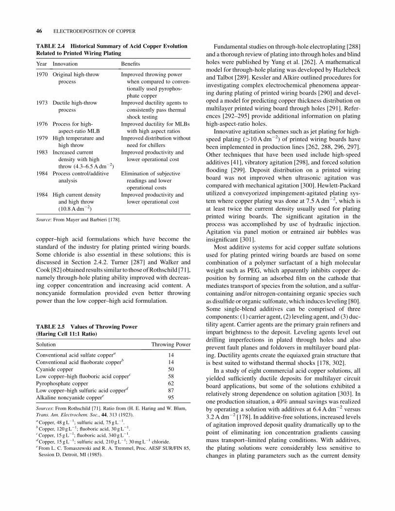
copper–high acid formulations which have become the
standard of the industry for plating printed wiring boards.
Some chloride is also essential in these solutions; this is
discussed in Section 2.4.2. Turner [287] and Walker and
Cook [82] obtained results similar to those ofRothschild [71],
namely through-hole plating ability improved with decreas-
ing copper concentration and increasing acid content. A
noncyanide formulation provided even better throwing
power than the low copper–high acid formulation.
Fundamental studies on through-hole electroplating [288]
and a thorough review of plating into through holes and blind
holes were published by Yung et al. [262]. A mathematical
model for through-hole plating was developed by Hazlebeck
and Talbot [289]. Kessler and Alkire outlined procedures for
investigating complex electrochemical phenomena appear-
ing during plating of printed wiring boards [290] and devel-
oped a model for predicting copper thickness distribution on
multilayer printed wiring board through holes [291]. Refer-
ences [292–295] provide additional information on plating
high-aspect-ratio holes.
Innovative agitation schemes such as jet plating for high-
speed plating (>10A dm�2) of printed wiring boards have
been implemented in production lines [262, 288, 296, 297].
Other techniques that have been used include high-speed
additives [41], vibratory agitation [298], and forced solution
flooding [299]. Deposit distribution on a printed wiring
board was not improved when ultrasonic agitation was
compared with mechanical agitation [300]. Hewlett-Packard
utilized a conveyorized impingement-agitated plating sys-
tem where copper plating was done at 7.5A dm�2, which is
at least twice the current density usually used for plating
printed wiring boards. The significant agitation in the
process was accomplished by use of hydraulic injection.
Agitation via panel motion or entrained air bubbles was
insignificant [301].
Most additive systems for acid copper sulfate solutions
used for plating printed wiring boards are based on some
combination of a polymer surfactant of a high molecular
weight such as PEG, which apparently inhibits copper de-
position by forming an adsorbed film on the cathode that
mediates transport of species from the solution, and a sulfur-
containing and/or nitrogen-containing organic species such
as disulfide or organic sulfonate, which induces leveling [80].
Some single-blend additives can be comprised of three
components: (1) carrier agent, (2) leveling agent, and (3) duc-
tility agent. Carrier agents are the primary grain refiners and
impart brightness to the deposit. Leveling agents level out
drilling imperfections in plated through holes and also
prevent fault planes and foldovers in multilayer board plat-
ing. Ductility agents create the equiaxed grain structure that
is best suited to withstand thermal shocks [178, 302].
In a study of eight commercial acid copper solutions, all
yielded sufficiently ductile deposits for multilayer circuit
board applications, but some of the solutions exhibited a
relatively strong dependence on solution agitation [303]. In
one production situation, a 40% annual savings was realized
by operating a solution with additives at 6.4A dm�2 versus
3.2A dm�2 [178]. In additive-free solutions, increased levels
of agitation improved deposit quality dramatically up to the
point of eliminating ion concentration gradients causing
mass transport–limited plating conditions. With additives,
the plating solutions were considerably less sensitive to
changes in plating parameters such as the current density
TABLE 2.4 Historical Summary of Acid Copper Evolution
Related to Printed Wiring Plating
Year Innovation Benefits
1970 Original high-throw
process
Improved throwing power
when compared to conven-
tionally used pyrophos-
phate copper
1973 Ductile high-throw
process
Improved ductility agents to
consistently pass thermal
shock testing
1976 Process for high-
aspect-ratio MLB
Improved ductility for MLBs
with high aspect ratios
1979 High temperature and
high throw
Improved distribution without
need for chillers
1983 Increased current
density with high
throw (4.3–6.5A dm�2)
Improved productivity and
lower operational cost
1984 Process control/additive
analysis
Elimination of subjective
readings and lower
operational costs
1984 High current density
and high throw
(10.8A dm�2)
Improved productivity and
lower operational cost
Source: From Mayer and Barbieri [178].
TABLE 2.5 Values of Throwing Power
(Haring Cell 11:1 Ratio)
Solution Throwing Power
Conventional acid sulfate coppera 14
Conventional acid fluoborate copperb 14
Cyanide copper 50
Low copper–high fluoboric acid copperc 58
Pyrophosphate copper 62
Low copper–high sulfuric acid copperd 87
Alkaline noncyanide coppere 95
Sources: From Rothschild [71]. Ratio from (H. E. Haring and W. Blum,
Trans. Am. Electrochem. Soc., 44, 313 (1923).aCopper, 48 gL�1; sulfuric acid, 75 gL�1.bCopper, 120 gL�1; fluoboric acid, 30 g L�1.cCopper, 15 gL�1; fluoboric acid, 340 gL�1.dCopper, 15 gL�1; sulfuric acid, 210 gL�1; 30mgL�1 chloride.eFrom L. C. Tomaszewski and R. A. Tremmel, Proc. AESF SUR/FIN 85,
Session D, Detroit, MI (1985).
46 ELECTRODEPOSITION OF COPPER

and level of agitation [304]. Byle and Bratin [305] also
studied the effects of additives.
Yung et al. [288] utilized a gap cell, which provided
accurate nondestructive profile measurements without te-
dious cross sectioning to show that agitation, which is
necessary inside the holes to replenish the plating solution,
is also necessary to provide a certain amount of agitation on
the surface of the board.
Pulsed-current techniques (discussed in detail in Section
1.10 on current modulation techniques) are claimed to offer
benefits for plating of printed wiring boards. However, aside
from Engelhaupt [258], no other manufacturing process
based on this technology has been reported [262].
Nonuniform copper plating on printed wiring boards may
be attributed to nonuniform anode currents due to high
contact resistances between anode hooks and anode rods.
Turner [306] developed an anode hook design to make a
stable low-resistance contact by clamping the hook to the
anode rod. Use of titanium for the hook and rod resulted in
a low-maintenance-contact system.
Optimizing the performance of a plating process does not
need to involve extensive, tedious testing. The traditional
approach of examining one variable at a time while holding
all others constant not only requires repeated tedious experi-
ments but also allows bias error in each measurement [307].
Use of factorial, screening, response-surface designs, or
Taguchi techniques allows for accurate solutions from a
minimum of test runs [308]. Any of these approaches in
studying the effects of many variables is highly recom-
mended for both research and production activities.
Barringer and Carano [309] used the Taguchi technique to
optimize the leveling of an acid copper plating solution for
printed wiring boards. The effects of temperature, leveler
(one component included in the addition agent), and ratio of
sulfuric acid to copper metal were investigated. The best
leveling was obtained at the low temperature, increasing the
ratio of sulfuric acid to copper resulted in some slight
improvement of leveling, and additions of leveler produced
no improvements. Taguchi techniques were applied by Wan
and McCaskie [307] to elucidate the relative importance of
various process parameters on dendrite formation in an acid
copper system.Chloride and arsenic concentrationswere two
critical factors that affected dendritic growth, while lead and
temperature exerted little effect. Elbs and Rasmussen [310]
utilized Taguchi techniques for optimizing the current effi-
ciency of a cyanide copper solution.
An important requirement of copper deposits is that they
have sufficient strength to withstand subsequent soldering of
the circuits. During this operation, high forces are generated
by differential expansion of the board material (usually
epoxy glass) and the copper. Therefore the copper must be
either strong enough to contain and deform the epoxy glass
or have sufficient elongation to be stretched without frac-
ture [311]. With the proper additives, fine-grained deposits
with tensile strengths around 345MPa and a minimum
elongation of 10% are routinely produced [41].
Most of the studies on the ductility of copper deposits for
printed circuit boards (PCBs) have been done under a
uniaxial stress state. However, the stress state of electrode-
posited copper in through holes of a PCB is definitely biaxial.
Therefore Ye et al. [312] correlated cathodic overpotential,
solution composition, and aging with characteristics such as
crystallographic texture, roughness, and ductility. Copper
foils with a low [220] preferred crystallographic orientation
and a smooth surface were obtained when deposition was
done at 87–113mV cathodic overpotential from solutions
with a low chloride content (<40 ppm). Highest ductilities
were achieved under these plating conditions,
Kang et al. [313] studied surface morphologies of foils
with different textures. Increasing solution temperature and
decreasing current density changed the texture from hl11i toh110i. The mechanical properties at elevated temperature of
a proprietary formulation for multilayer board plating were
evaluated in detail by Fox [314]. The deposit was found to
exhibit adequate localized ductility, although, as is generally
the case for electroplated copper, its final elongation after
fracture was lower than that for wrought, annealed copper.
Merchant reported on the defect structure, isothermal anneal
kinetics, and thermal response of electrodeposited
copper [224, 225, 315, 316].
2.13 PATTERNED ELECTRODEPQSITION
FOR MICROELECTRONICS
Computers, microprocessors, and other microelectronic de-
vices could not exist without the technology of depositing
thinmetal or alloy films with fine lithographic patterns [317].
Romankiw et al. [318–321] have demonstrated the capabil-
ities of resist patterned electroplating for the past two dec-
ades. Dukovic [317] suggests that there are three trends that
appear to be propelling patterned electrodeposition into a
phase ofmajor expansion. First, high-speedmachines require
the high conductivity of copper, and acid copper plating is
simple and capable of reaching high rates. Second, the
pattern replication powers of electrodeposition are ideally
suited to the level of miniaturization required for wiring
structures. Third, demands for cost reduction have increased
the importance of reducing the capital and operating ex-
penses associated with metal deposition processes, and it is
therefore likely that electroplated copper thin film, which is
important today, will continue to play a central role in the
future.
IBM researchers have successfully implemented copper
electroplating technology for the fabrication of chip inter-
connect structures [2a, 2b, 321a]. The process, termed dam-
ascene copper electroplating, meets the challenges of filling
trenches and vias with copper without creating a void or
PATTERNED ELECTRODEPQSITION FOR MICROELECTRONICS 47

seam. Under proper conditions, electroplating inside
trenches occurs preferentially in the bottom, leading to
void-free deposits, a phenomenon referred to as superfilling.
Proprietary additives are used in the plating solution to
produce the superfilling properties.
Electrodeposited bonding bumps are indispensable mi-
croconnectors for high-density interconnection in recent
microelectronics applications. The bumps generally have
mushroom shape and are deposited onto dot-shaped cavities
of several 10–200 mm in diameter formed by photoresist.
Kondo et al. [322] discussed the shape evolution of copper
bumps, and Dukovic [323] developed a two-dimensional
numerical computation of tertiary current distribution.
High-speed selective jet electrodeposition has also been
used to produce deposits in a selective manner without the
need for masking [324]. The principle is that a nonsub-
mersed, free-standing electrolyte jet impinges onto a sub-
strate and deposition occurs within the impingement region,
with little or no deposition occurring in the surrounding
areas. Booking [324] determined the effects of temperature,
velocity, and concentration during high-speed selective jet
plating in an acid copper sulfate solution without additives.
The development of laser-enhanced electroplating pro-
cesses offers a promising technique for high-speed and mask
less selective plating and/or as a repair and engineering
design change scheme for microcircuits [300, 325–328]. For
this, temperature is used to modify the position of the
equilibrium potential in a localized region so that electro-
deposition is driven by the potential difference between
this region and the nonirradiated regions. Use of a focused
argon laser beam (488 nm) in an acid copper solution pro-
vided plating rates as high as 25 mms�1 [300]. Bindra
et al. [327, 328] discussed the mechanism of laser-enhanced
acid copper plating and Paatsch et al. [329] reported on laser-
induced deposition of copper on p-type silicon. It was
demonstrated that the increase in the plating rate under laser
illumination results principally from photoinduced heating
of the electrode surface [328].
2.14 ELECTROFORMING
Copper finds extensiveuse in electroforming [330, 331].Acid
sulfate with periodic reversal of current [236, 332], acid
sulfate with oxygen reduction additive, and pyrophosphate
solutions provide excellent properties for aerospace applica-
tions [236]. However, although acceptable properties are
attainable via pyrophosphate deposition, very little electro-
forming is done with these solutions. Electroforming with
acid copper or nickel is used as one of the primarymethods of
fabricating the outer shells of regeneratively cooled thrust
chambers for advanced design rockets and other applications.
Typically the process involves filling machined (or
etched) channels with wax, making the wax conductive with
silver powder, plating thick copper to seal over the channels,
and then removing the wax. Some thrust chamber require-
ments for copper require that the deposits retain useful
mechanical properties and metallurgical structure at tem-
peratures up to 400�C. The electroformed copper deposits
often contain some oxygen, and this can be deleterious at
high temperatures because hydrogen can combine with the
oxygen and produce water.
With the high temperatures involved, steam pressure
generated by the reaction often exceeds the strength of the
copper and causes plastic deformation and/or tearing, fre-
quently manifesting itself by grain boundary cracking or
cavities [333, 334]. This problem is avoided by using an
oxygen control additive such as sugar [335, 336] or potas-
sium aluminum sulfate [337].
All of the pentoses are suitable for use in the copper sulfate
solution, such as xylose, arabinose, ribose, and lyxose. These
materials act as oxygen scavengers in the solution by picking
up oxygen and thereby preventing the anodes from being
oxidized [172]. Table 2.6 includes the gas and carbon content
of a variety of copper deposits and clearly shows the high
purity attainable with an oxygen control additive such as
d-xylose [338].
Farmer et al. [339], in evaluating copper for a physics
accelerator application, noted that copper deposited from
acid sulfate solution containing one set of proprietary ad-
ditiveswas unstable during heat treatment and exhibited void
formation around 450�C. By contrast, another acid copper
solution with different proprietary additives formed no voids
when heated at 1000�C. Deposits from a cyanide solution
and an acid copper solution containing d-xylose also showed
no void formation after heating at 1000�C, giving further
proof that deposits with low carbon and gas contents
(Table 2.6) are stable at high temperatures.
Electroformed targets for a 14-MeVneutron source facility
did not require the high-temperature stability just discussed.
However, they did require a deposit elongation around
20% because of a forming operation after plating. This was
TABLE 2.6 Carbon and Gas Contents of Various Copper
Electrodeposits and OFHCa Copper
Content (wt. ppm)
Plating Solution C H O N
Low copper–high acid proprietary 50 11 50 5
d-Xyloseb 12 1 11 2
Pyrophosphate proprietary 21 6 140 17
High copper–low acid proprietary 190 14 50 9
Cyanide NA 3 53 6
OFHC (wrought) 90 4 50 <10
Source: From Dini [338].aTrademark: American Metal Climax, Inc.bOxygen control additive.
48 ELECTRODEPOSITION OF COPPER

obtained by using a medium-copper (150 gL�1 copper sul-
fate), high-acid (188 gL�1 sulfuric acid) formulation [340].
Copper deposits usually contain small amounts of other
impurities besides oxygen, and these can affect properties
such as electrical resistivity [3]. Hydrogen is present in
different bound states in the deposits and the total amount
of hydrogen is often five to six orders of magnitude larger
than the equilibrium solubility of hydrogen at room temper-
ature [341]. It is most likely that the hydrogen is bound to
crystal lattice defects such as vacancies and dislocations or
adsorbed at the grain boundaries or present in microvoids.
Deposits obtained at low current densities contain a larger
amount of hydrogen than those obtained at high current
densities.
Hydrogen is evolved from the deposits as a function of
temperature with the major amount being eliminated at tem-
peratures around 450�C [341]. Sulfate (0.071–0.099wt %)
and sulfide (0.040–0.069wt %) have been found in deposits
from acid copper solutions. These impurities decreased
with the increase in plating temperature, with the increase
in acidity of the plating solution, and with the addition of
0.1 g L�1 gelatin [342].
Strongly enhanced ductility (up to 40%) and reflectivity
were achieved in the presence of dimethylamino deriva-
tives [98]. The ductility of the coatings in contrast to the
tensile strength appeared to be correlated to the amounts of
codeposited carbon and sulfur.An elongation of 15%and low
stress were obtained from solutions containing polypropyl-
ene ether. These deposits were essentially sulfur free, with
carbon and nitrogen contents of about 0.015 to 0.003 and
0.001wt % [110]. A high-throw acid copper solution has
been used with glue and phenol sulfonic acid for electro-
forming of bellows [343].
Although not electroforming, very thick deposits (around
5000 mm) were produced on the outer surface rotor of a
300-MVA superconducting generator. This was done in acid
sulfate solution with a proprietary brightener. Deposit prop-
erties were yield strength around 210MPa, elongation 15%,
and high electrical conductivity at cryogenic tempera-
tures [344]. Radio-frequency quadrapole accelerator com-
ponents up to 4m long were plated with 250 mm copper in an
acid sulfate solution containing a brightener system [345].
2.15 HIGH-SPEED ELECTROPLATING
A current density of 300Adm�2 or more is practical for
depositingmost metals if the solution flow rate is in the range
of 1.0–1.2m s�1, depending on the topography of the surface,
the solution viscosity, and other factors [346]. High current
densities for achieving fast rates have been used in both
copper sulfate and copper fluoborate solutions. Large varia-
tions in the copper and sulfuric acid concentrations had no
significant effect on the appearance of deposits from the
sulfate solution. The tensile strength of copper deposited
with turbulent flow in a sulfate solution increased from 350
to 450MPa as the current density was raised from 100 to
300A dm�2, which increased the deposition rate from 25 to
75 mmmin�1. High-speed copper deposited in a fluoborate
solution exhibited a lower tensile strength, 280 to 350MPa
over the range of 100–300A dm�2. However, all of these
values are higher than those reported for copper deposited at
conventional rates.
High-speed copper plating has been developed for com-
mercial applications such as electroforming of flexible
printed circuits [347], in-mold plating of polymeric materi-
als [348], and plating of round bars [349]. A process for
electroforming copper circuit paths on a reusable metal
substrate and transferring the circuitry to a flexible polymeric
surface coated with adhesive has been advanced to produc-
tion. The copper circuit paths are electroformed at rates up to
50 mm min�1 using fast-rate electrodeposition technology.
The process does not generate spent etching solutions or
plating rinse water and costs can be 70–80% of those
associated with the conventional etched-circuit process for
high-volume production. Another benefit is that high-speed
deposition conserves equipment and floor space [348].
A combination of high-speed plating with pulsed current
(fast-rate, interrupted current, FRIC) allows for deposition of
copper with different structures at rates of 50 mm min�1 or
higher [350]. By controlling the frequency and/or duty cycle
with the high-speed deposition rate, it is possible to tailor the
deposit structure to suit the application. For example, with
applications that need structural strength particularly at
corners, the FRIC technique at high frequency would be
used to promote growth of mainly polycrystalline copper
which would be equally strong in all directions. By contrast,
for applications such as wire coatings that require maximum
electrical conductivity, columnar structures produced at
moderate frequency are preferred [350].
For agitation of the electrolyte, forced circulation across
the cathode by pumping electrolyte is most commonly used,
although ultrasonic agitation and gas sparging have also been
investigated [351]. When plating wire and strip using direct
current, the deposition rate can be increased by intensifying
the electrolyte flow, by optimizing the gap between the
cathode and anode, and by the use of high-performance
electrical contacts [352].
2.16 DIAMOND TURNING
Diamond-turning surface finishing uses single-point dia-
mond tools on a precision lathe under precisely controlled
machine and environmental conditions. Diamond tools
are used when it is necessary to machine the smoothest
possible surface texture. When the surface to be cut is one
of the preferred diamond-turnable materials such as copper,
DIAMOND TURNING 49

electroless nickel, or aluminum, surface textures as smooth
as 1 nm can be obtained. Coatings offer significant advan-
tages for diamond-turning applications inasmuch as they can
be applied to lightweight substrates such as aluminum or
beryllium, and copper coatings produced in acid sulfate
solutions have been used in many applications. A number
of 1.3-m-diameter molybdenum parts required form accu-
racy of approximately 250A�, and this was obtained by
coating the parts with 0.3–0.45mm of copper prior to dia-
mond turning [52]. A physical vapor deposition process was
used to provide an initial, thin (6-mm) adherent copper layer,
and this was followed by thick plating in an acid copper
solution containing proprietary additives. An important re-
quirement for these parts, as well as for many other diamond-
turning applications, is long-term microstructural stability.
If the deposit undergoes recrystallization after machining,
the precise surface finish is degraded. Copper deposits have
been shown to markedly soften after storage at room tem-
perature for 30 days [353]. For example, copper mirror
surfaces for the Antares laser system changed over a six-
month period due to recrystallization [51]. The problem was
eliminated by employing a low-temperature heat treatment
(1 h at 250�C). This same treatment provided stability for the
proprietary copper used for the 1.3-m-diametermolybdenum
parts mentioned earlier [52].
Rao and Trager [354] reported that copper for diamond
turning should have a grain size from about 200 to 500A�and
a hardness from about 250 to 320 Knoop (15-g load). An
additive comprising a mixture of phenazine dyestuffs in the
combination from about 30 to 40% by weight of a Janus
Green B–type dyestuff and from about 70 to 60% by weight
of Safranine T provided these properties.
By judicious choice of plating operating conditions, such
as current density, pH, solution composition, and additive
concentration, it is possible to deposit coatings that are in a
stress-free state. A plot of current density versus stress was
used to define conditions for depositing 1-mm-thick copper
with zero stress on glass substrates and on pyrex optics. This
deposit was capable of withstanding single-point diamond
turning to provide an optical surface and was able to with-
stand heating at 250�C for 4 h without degradation of the
metal–glass bond [53].
Occasionally, a phenomenon referred to as black spots has
been obtained. These are small, localized defects noted on
electroplated copper after single-point diamond turning.
Analysis of these spots has revealed oxides, sulfates, and
chlorides, materials which are components of the plating
solution [355, 356]. It is speculated that the most likely cause
of these defects is a void or pit exposed by the diamond-
cutting tool. In an effort to eliminate these minuscule pits
Dini et al. [356] evaluated plating under reduced pressure
(around 100 torr). Copper deposits produced under these
conditions exhibited finer and denser grain structure and a
reduced surface roughness.
2.17 MISCELLANEOUS
2.17.1 Magnetics
Effects of magnetic fields on electroplating of copper were
investigated by Takeo et al. [357], who noted a reduction in
energy required for depositionwith increasingmagnetic field
as a consequence of reduced concentration overpotential.
Changes in structure and hardness were also noted as the
applied magnetic field strength was increased. Ismail and
Fahidy [358] studied the effect of uniformmagnetic fields on
the morphological properties of fine-mesh metal screen
deposits. Popov et al. [359] provided some correlation be-
tween dendritic growth and copper powder formation.
2.17.2 Striations
Occasionally spiral patterns (striations) that follow the
streamlines of the fluid are obtained during electrodeposition
of copper, zinc, and silver [360]. This is accompanied by
small or negative polarization resistance and is typically
observed only below a certain current density. The range of
current density depends on the electrolyte and its concen-
tration. Studies with rotating hemispherical electrodes
(RHEs) revealed no striations in the deposition of copper
from sulfate solution unless a certain amount of gelatin was
added. With increasing additions of gelatin (10–20 ppm), the
polarization curve became progressively steeper, vertical,
and finally S shaped while shifting to a more negative
potential [360]. Spiral patterns were also observed in acid
copper sulfate solutions containing PEGs and chloride [89].
2.17.3 Underpotential Deposition
Underpotential deposition (UPD) involves formation of up to
a monolayer of atoms on foreign substrates at potentials that
are more positive than the potential of the reversible depo-
sition in the same solution, that is, before bulk deposition can
occur. The fact that UPD exists means that the chemical
potential of adatoms deposited at the underpotentials is
different from that of the corresponding bulk metal. The
adatoms aremore strongly bound to the surface of the foreign
substrate than to the surface of its own species [361, 362].
The likelihood that UPD plays an important role in
electroplating processes has long been recognized [363]. An
example wherein UPD plays an important role is in the
electroplating of gold where ions of metal (or semimetal)
serve as brightening agents for gold plated from cyanide and
noncyanide solutions. Gold deposition proceeds in the region
of UPD of the foreign metals, which are incorporated only at
trace levels in the deposit. These foreign metals act as
brighteners because of their strong influence on the nucle-
ation process [363]. With copper, it has been demonstrated
that the UPD of Pb or Sn on copper can be used to produce
electroplated Cu–Pb and Cu–Sn alloys, with small amounts
50 ELECTRODEPOSITION OF COPPER

of alloyed Pb and Sn. This is done in acid solutions that do not
contain complexants. These alloys are of interest as possible
on-chip wiring for very large scale integration where the
content of alloying agent must be kept small in order to
maintain a low resistivity [363]. Some other studies on UPD
include Cu on Au [364] and Cu and Ag on Pt [365].
PART BCYANIDE COPPER*
2.18 HISTORY AND DEVELOPMENT
Before 1915 copper cyanide solutions were invariably pre-
pared by dissolving copper carbonate in alkali cyanide. The
use of tartrates is mentioned in early references [366, 367],
but their value apparently was not fully recognized. An
exception was the combination cleaning and plating solution
described by Watts [368] in 1915. Deposits from these early
solutions were relatively thin and were used largely as bases
for oxidized and other decorative types of finishes.
The first commercially successful high-efficiency solu-
tionwas introduced in 1938. It was used extensively through-
out the automotive industry in subsequent years for plating
zinc die castings as well as steel parts. High rates of depo-
sition were achieved by operating at temperatures around
80�C. Alkali was added to improve anode corrosion and to
increase the conductivity of the solution [369]. Alkali thio-
cyanate was used by Wernlund [370] in 1941 to brighten the
deposits. Successful commercialization of the process re-
quired the use of specific surface-active agents to sequester
organic contaminants and prevent pitting [371]. This solution
permitted deposition of smooth, bright deposits in the thick-
ness range of 25–50 mm. The basic formulations of the
proprietary high-efficiency solutions now in commercial
operation are similar to these, except that thiocyanate and
other active sulfur-containing constituents are not recom-
mended in the new processes.
The next major advance in high-efficiency cyanide copper
solutions was achieved by employing periodic reverse plating
cycles [372]. Other current manipulation techniques such as
interrupted current are occasionally used to modify the prop-
erties of the coatings. Awide variety of addition agents have
been developed; this is covered in Section 2.22. Reviews of
cyanide copper plating can be found in [373–379].
2.19 APPLICATIONS
Cyanide copper plating is used throughout themetal-finishing
industry for many applications, although not as extensively
today as in the 1970s because of environmental issues.
Horner [380] estimates that present usage is less than 50%
of that in the 1970s. Possible site contamination, worker
safety considerations, and highwaste treatment and reporting
costs are some drawbacks [381].
Applications include as an undercoat for other deposits
to protect basis metal or promote adhesion; for surface
improvement in buffing, soldering, lubricity, rotogravure,
printing rolls, and decorative plating of zinc die cast-
ings [382–385]; in plating of steel parts with copper before
nickel and chromium plating [384, 385]; as a stopoff to
prevent case hardening on selected areas of ferrous metal
surfaces; and in plating of coinage [386, 387]. A high-speed
cyanide copper plating process is used to produce heavy
coatings of copper on steel wire for electrical use. For
noncorrosive environments, aluminum is often plated with
copper cyanide after zincating. This is followed by a deco-
rative nickel–chromium coating [388].
2.20 FUNCTIONS OF MAJOR SOLUTION
CONSTITUENTS
2.20.1 Copper Cyanide
Typical formulations for cyanide solutions are give in
Table 2.7. Copper cyanide is insoluble in water but dissolves
in aqueous solutions containing alkali metal cyanides to
form four stable soluble complexes and free species in
water: CuCNaq, [Cu(CN)2]�, [Cu(CN)3]
2�, [Cu(CN)4]3�,
and Cuþ and CN�. In all four oxidation complexes, the
oxidation number of copper is þ 1. A model of copper
discharge from cyanide electrolyte was developed by Dudek
and Fedkiw [389].
Deposition occurs from the CuðCNÞ �2 and CuðCnÞ 2�
3
complexes [390]. Cuprous cyanide complexes shift the cop-
per deposition potential to more negative values which avoid
displacement deposition on less noble substrates. The pre-
dominant copper cyanide species discharged in copper strike
plating is proposed to beCuðCNÞ 2�3 ; although CuðCNÞ 3�
4 is
at a higher concentration, it is not as electroactive. These
kinetics give rise to the inherent good “macroscopic throwing
power” observed in the cyanide solution [391]. Additional
information on kinetics can be found in [392].
The Taguchi method was used to evaluate a number of
parameters in a copper cyanide solution. An increase in
copper concentration and a decrease in potassium cyanide
resulted in good current efficiencyover awide current density
range. Hydroxide and carbonate concentration were of sec-
ondary importance [393].
2.20.2 Free Cyanide
The alkali cyanide in excess of the tricomplex salt
Na2[Cu(CN)3] is termed free cyanide. The ratio of the free*Revision of section by R. R. Bair and A. K. Graham in the 1974 edition.
FUNCTIONS OF MAJOR SOLUTION CONSTITUENTS 51

cyanide to the coppermetal content in the strike andRochelle
solutions is somewhat higher than in the high-efficiency
solutions. This accounts, in part, for the lower cathode
efficiency. Hydrogen is simultaneously liberated at the cath-
ode in the strike and Rochelle solutions, and this hydrogen
evolution provides additional cleaning. Strike and Rochelle
solutions are also operated at a relatively high free cyanide–
metal ratio in order to produce the desired type of deposit.
The excellent adhesion of strike deposits can be attributed
largely to the high free cyanide combined with low metal,
which minimizes any tendency to form nonadherent immer-
sion deposits. Free cyanide is essential in all cyanide copper
plating solutions in order to obtain good corrosion of the
copper anodes. If it is too low, the anodes polarize and
become coated with an insulating film. Free cyanide con-
tributes to conductivity in strike and Rochelle solutions, but
not significantly in high-efficiency solutions that contain
alkali and higher concentrations of the complex copper ions.
The concentration of the free cyanide increases at higher
temperatures, since lower complexes are formed and free
cyanide is thereby liberated [390]. Free cyanide is normally
determined by titrating a sample of the solution with silver
nitrate at or below room temperature using potassium iodide
as an indicator.
2.20.3 Sodium or Potassium Hydroxide
Sodium or potassium hydroxide is added to high-efficiency
solutions primarily to provide good electrical conductivity
and to improve throwing power. Alkali is also essential in
these solutions for good anode corrosion. The brightness of
the deposits from high-efficiency solutions is also influenced
by the alkali metal hydroxide. Usually only small amounts of
caustic are added to strike or Rochelle solutions for adjusting
or maintaining the pH within the proper range. Many users
of high-efficiency cyanide copper solutions base their for-
mulations on sodium cyanide to complex the cyanide copper
and add potassium hydroxide as a means of introducing the
potassium ion.
2.21 COMPARISON OF SODIUM AND
POTASSIUM FORMULATIONS
The complex salts formed with sodium or potassium cyanide
are similar in composition, but the potassium salts are more
soluble. Horner [394] compared the throwing power and
efficiencies of sodium and potassium formulations and the
effects of free cyanide, carbonate content, and other factors.
He concluded that potassium salts offered no advantage for
cathode efficiency over sodium salts but did show improved
throwing power. Hatherley et al. [387] reported that sodium
and potassium formulations each possess various advantages
and disadvantages. Conductivity is higher in potassium
solutions, especially at high concentrations of carbonate.
Cathode polarization curves also favor potassium formula-
tions over sodium. By contrast, sodium solutions exhibit less
of a risk of anode passivation. Juhos et al. [395] also found
that sodium formulations favored the anode reactions.
Hatherley et al. [387] suggest that commercial considerations
might be used to specify optimum carbonate level where the
advantage of high conductivity has to be set against reduced
cathode efficiency.
2.21.1 Carbonate
Carbonate exerts a strong buffer action at a pH of 10.8–11.5 in
strike and Rochelle solutions [396, 397] and facilitates pH
control. It also reduces anode polarization in these solutions.
TABLE 2.7 Copper Cyanide Solution Formulations
Strike (g L�1) Rochelle (g L�1) High Efficiency (g L�1)
Constituent Typical Limits Typical Limits Typical Limits
CuCN 22 15–30 26 19–45 75 49–127
NaCN 33 23–48 35 26–68 102 62–154
or
KCN 43 31–64 — 136 76–178
Na2CO3 15 0–15 30 15–16
NaOH — — — 15 22–37
or
KOH — — — 15 31–52
Rochelle salt 15 15 45 30–60 — —
(KNaC4H4O6 � 4H2O)
By Analysis
Copper 16 11–21 18 13–32 55 34–89
Free cyanide 9 6–11 6 4–9 19 10–20
52 ELECTRODEPOSITION OF COPPER

Nobeneficial effects of carbonate have been observed in high-
efficiency solutions that contain substantial amounts of caus-
tic. Commercial high-efficiency cyanide copper solutions
contain an average of about 50 gL�1 sodium carbonate. It
is formed by oxidation of the cyanide radical at the surface of
polarized anodes or insoluble anodic metal surfaces. Absorp-
tion of carbon dioxide from the air by the caustic alkali in the
solution and hydrolysis of the cyanide are other sources of
carbonates formed in the high-efficiency solutions.
The oxidation of cyanide should be avoided because it
increases the cyanide consumption, causes a rapid buildup
of carbonates, and complicates control of free cyanide.
Concentrations up to about 90 g L�1 sodium carbonate or
120 gL�1 potassium carbonate have no significant effect in
reducing the plating speed of high-efficiency solutions. If
maximum plating speed is required, however, the concentra-
tions should be controlled below these levels.
2.21.2 Tartrates
Tartrates are used primarily in the low-efficiency solutions. It
is believed that the potassium–sodium tartrate or Rochelle
salt (KNaC4H4O6 � 4H2O) forms temporary complexes with
copper by reacting with products of electrolysis produced
in the anode film. Solutions containing tartrates may be
operated with lower free cyanide and at higher current
densities and efficiencies without impairing anode corro-
sion [396, 398]. Obtaining better quality deposits by the use
of Rochelle salt is associated in part with the formation of
complex salts which are probably present in the cathode film.
Solutions are normally operated with about 45 g L�1 Ro-
chelle salt. Wagner and Beckwith [398] claimed that the
optimum concentration was about 22.5 g L�1, with some-
what lower efficiencies being obtained at higher values.
The substitution of sodium–potassium citrate for Rochelle
salt [399] has been investigated and several other proprietary
compounds of a similar type are claimed to offer advantages.
2.22 ADDITION AGENTS
Additives for cyanide copper systems include compounds
having active sulfur groups and/or containing metalloids
such as selenium or tellurium. Other agents that haveworked
are organic amines or their reaction products with active
sulfur-containing compounds; inorganic compounds con-
taining metals such as selenium, tellurium, lead, thallium,
antimony, and arsenic; nitrogen and sulfur heterocyclic
compounds; and unsaturated alcohols, saccharin, and PEG.
An extensive listing of additives used in acid and cyanide
copper prior to 1959 can be found in [374] and more recent
information in [400–411]. Of interest are data from Table 2.2
in the section on acid copper plating which lists only one
U.S. patent for cyanide copper plating since the mid-1970s
compared to over 60 for acid copper.
2.23 SOLUTION TYPES: STRIKE ANDROCHELLE SOLUTIONS
Copper cyanide solutions may be classified in three catego-
ries: strike, Rochelle, and high efficiency. Strike solutions are
used extensively to apply relatively thin coatings of copper as
an undercoating for other metals. Rochelle solutions, in
general, are not as sensitive to contamination as the high-
efficiency solutions and are used in applications where an
intermediate thickness of copper is applied. Deposits from
these solutions vary from dull to semibright; the brightness
or luster is not of major importance for most applications.
Copper strike solutions are used for applying a thin
coating of copper on aluminum and zinc die castings before
plating with other metals [384]. The adherent copper coating
prevents chemical attack when these substrates are subse-
quently plated with heavier coatings from other solutions.
The thickness of strike deposits normally varies from about
0.5 to 1 mm, although it may sometimes be as high as 2.5 mm.
The heavier strike depositsmust be usedwhen the subsequent
plating operation is from an acid electrolyte. For instance,
the copper strike deposit on zinc die castings must be three to
five times as heavy for subsequent acid copper plating as
compared with cyanide copper plating.
The bond strength between electroless nickel and a variety
of aluminum alloys is higher when a copper strike is
used [412]. Besides showing good adhesion of subsequent
electrodeposits, the copper strike from cyanide solutions is
an additional cleaning operation. Furthermore a thin copper
strike (1.3 mm) under lead coatings over steel has shown
improved protective value in atmospheric exposure tests
compared to lead coatings alone [413, 414]. Aluminum parts
can be plated in a barrel if the free cyanide in the copper strike
is high enough (15–20 gL�1) to prevent displacement of
copper on zinc [415]. A good review of copper cyanide
striking is provided by Mohler [416].
2.24 OPERATING CONDITIONS AND
SOLUTION CHARACTERISTICS
The operating conditions of strike and Rochelle solutions are
given in Table 2.8. Strike solutions are usually operated in the
temperature range of 40–60� C. The cathode efficiencies
are relatively low (10–60%) in the normal plating range of
1.0–3.2A dm�2. The solution composition and operating
characteristics vary widely in actual commercial practice.
Many users prefer to add 15–30 gL�1 sodium carbonate.
When steel parts are plated, 15–30 g L�1 sodium hydroxide
may be added to improve the conductivity. Rochelle salt, or
its equivalent, is sometimes used to improve anode and
cathode characteristics.
Because of the higher cathode efficiency, heavier deposits
can be more practically produced from Rochelle solutions
OPERATING CONDITIONS AND SOLUTION CHARACTERISTICS 53

than from strike solutions. These plating characteristics are
achieved by operating at higher temperatures, controlled pH,
and higher metal concentration and adding substantial
amounts of Rochelle salt to the solution. The average cathode
efficiency is approximately 50% higher than that obtained
from strike solutions. The anode and cathode efficiencies
vary with the temperature and degree of agitation [396].
Rochelle solutions are normally operated without metal-
containing addition agents, but lead had been used as a grain
refining and brightening agent [417].
Polarization phenomena in copper cyanide solutions have
been extensively investigated [387, 390, 396, 418, 419].
Hatherley and co-workers [387] reported that potassium-
and sodium-based solutions may both be operated at close to
100% cathode efficiencies but potassium solutions can sus-
tain efficient copper deposition to a higher maximum current
than can sodium. They also noted that increasing free cyanide
diminishes the limited current density that can be sustained at
maximum efficiency, and this relationship is linear for both
sodiumand potassium solutions.An increase in the carbonate
or hydroxide content is also associated with a reduction in
the maximum current for efficient copper deposition. Last,
the efficiency of solutions cannot be restored by precipitation
of carbonate with lime, nor by any of the other chemical
agents that have been proposed in the past [387, 390].
Graham and Read [396, 418, 419] defined the limiting
current density beyond which excessive polarization occurs
for a given set of solution variables. Excessive polarization
causes insulation of the anodes and usually necessitates their
removal for cleaning. Variations in metal content and free
cyanide have little effect on the limiting current density. If the
carbonate content is too high, the copper may act as an
insoluble anode without exhibiting excessive polarization.
Reducing the pH from 12.8 to as low as 10.3 does not greatly
alter the limiting current density. The presence of tartrates
does not overcome the tendency of the anodes to polarize
excessively, but the allowable current density is raised when
both carbonate and tartrate are present. If insoluble iron
anodes are used along with copper anodes, higher anode
current densities may be used because the iron anodes
depolarize the copper.
The throwing power of Rochelle solutions is superior to
that of high-efficiency cyanide solutions. Most of the pub-
lished data on throwing power are limited to current densities
below 1.0A dm�2. The factors influencing the throwing
power of Rochelle solutions when operated at more practical
current densities and temperatures may be quite different.
The greatest single factor contributing to good throwing
power and metal distribution appears to be associated with a
decrease in cathode efficiency with increasing current den-
sity. High efficiencies, in general, contribute to poor throw-
ing power, but there are also other factors, as discussed later.
2.25 MAINTENANCE AND CONTROL
Copper strike solutions in commercial use vary in metal
content but are usually maintained at a copper metal con-
centration of about 10–16 g L�1. Themetal content increases
during operation because the copper anode efficiency is
higher than the cathode efficiency. It is common practice to
use a combination of steel and copper anodes in the strike
solutions to obtain an overall anode efficiency equal to the
average cathode efficiency. The control of the critical free
sodium cyanide is simplified, and a more stable solution
composition is thereby attained. The free sodium cyanide
should be controlled within the range of 6–11 gL�1.
Continuous filtration of the strike solutions through acti-
vated carbon is recommended for the best results. This
prevents particle roughness on the shelf areas of the plated
parts and minimizes drag in of organic contamination into
subsequent plating solutions.
Control of the pH of Rochelle solutions is important for
obtaining the best performance. Operation within the pH
range of 12.2–12.8 is recommended [396]. The range
12.5–12.8 is preferred because the solution is buffered in
this range by the carbonate. Operation at a pH in excess of
12.9 should be avoided, owing to decreased anode efficien-
cies and chemical attack of the solution on zinc die castings.
The pH of Rochelle copper solutions can be determined
by a pH meter, by colorimetric methods, or by titrating with
hydrochloric or sulfuric acid. The first two methods are rapid
and simple; the titration method, however, has the advantage
of indicating directly the approximate excess of caustic
above the sulfo-orange sodium carbonate endpoint. The pH
at the sodium carbonate buffer point is approximately 11.5; it
canberaised to12.7by theadditionof0.75 g L�1caustic soda.
TABLE 2.8 Operating Conditions for Typical Cyanide
Solutions
Conditions Strike Rochelle
High
Efficiency
Temperature (�C) 40–60 55–75 60–80
Cathode current
density (A dm�2)
0.5–4 1.5–6.5 1–11
Anode current
density(A dm�2)
0.5–1 0.8–3.3 1.5–5
Efficiency range
Cathode (%) 10–60 30–90 70–99þAnode (%) 95–100 50–70 —
Ratio of anode to
cathode area
3:1 2:1 3:2
Agitation
Cathode rod Optional Preferred Either
or both
Air
Solution voltage (V) 6 6 0.75–4
Limiting thickness (mm) 2.5 13 >25
54 ELECTRODEPOSITION OF COPPER

Controlling the free-cyanide concentration of Rochelle
solutions within the range of 4–9 g L�1 is also important.
Excessive anode polarization is encountered at very low free
cyanide and the quality of the deposits is also adversely
affected. Operating with a significantly higher free-cyanide
concentration than recommended results in lower cathode
efficiencies and in the production of dull deposits that
are difficult to buff.
2.26 HIGH-EFFICIENCY CYANIDE
COPPER SOLUTIONS
Solutions that are formulated and operated under conditions
that give essentially 100% anode and cathode efficiencies are
classified in this category. The rates of deposition are appre-
ciably higher than can be obtained from strike or Rochelle
solutions.
Many of the high-efficiency cyanide copper solutions are
used for plating of automotive bright trim parts. As pointed
out earlier, Rochelle solutions may be used for plating
zinc die castings. Most installations, however, use high-
efficiency solutions in order to obtain the required thickness
relatively quickly. The brightness of deposits from the high-
efficiency solutions is also an important factor.
Copper is also plated from high-efficiency solutions on
selected surfaces of ferrous metal parts to prevent carbon
penetration during case hardening. Thickness requirements
vary from 13 to 25 mm, depending on the type of carburizing
medium used, time of treatment in the carburizing solution,
and type of surface finish on the steel. Another use of high-
efficiency solutions is the plating of steel wire with a heavy
coating of copper [420–422]. Part-to-part spread in deposit
thickness for barrel plating is considerably less for alkaline
solutions (cyanide, pyrophosphate, and amine) than for acid
solutions (sulfate and fluoborate) [423].
2.27 OPERATING CONDITIONS AND
SOLUTION CHARACTERISTICS
High-efficiency cyanide solutions are normally operated in
the temperature range of 60–80�C (see Table 2.8), with the
higher temperature preferred for maximum plating speed.
Many of the high-efficiency electrolytes are operated at
temperatures as low as 60�C to fit specific needs and equip-
ment. It is emphasized that a reduction in solution temperature
can restrict the width of bright plating range and maximum
usable current densities. The cathode current density range in
commercial practice varies from about 1 to 11Adm�2,
depending on the contour of the parts being plated. Automo-
tive parts are generally plated at current densities in the range
of 2–5.5A dm�2, whereas wire is plated from high-metal
solutions at current densities as high as 11Adm�1.Maximum
plating speeds are achieved with potassium formulated solu-
tions containing high metal and operated with vigorous
solution circulation. The solutions must be operated at sub-
stantially 100% cathode efficiency in order to produce good-
quality deposits and to avoid hydrogen evolution at the
cathode, which produces dull, burned deposits.
These high-efficiency solutions would normally be ex-
pected to have poor throwing power. However, metal distri-
bution on plated parts is better than would be predicted from
the efficiency factor alone. One reason for this is that the high
concentration of salts, particularly alkali, and high operating
temperatures greatly improve the conductivity and reduce
the difference in current density on protruding and recessed
areas. Rochelle salt solutions have good throwing power
because the cathode efficiency decreases with increase in
current density.
The anode current densities may vary from 1.5 to
5A dm�2. The anode efficiency under these conditions is
essentially 100%. At very low anode current densities
(0.2–0.6A dm�2), particles of copper may be formed or
generated at the anode surface through intercrystalline cor-
rosion. The particles settle on shelf areas of the parts and
produce serious roughness. Certain types of proprietary
organic addition agents are claimed to play an important
role in improving anode corrosion [424]. They apparently
form a thin organic film over the anode surface and thereby
promote smooth anode corrosion andminimize any tendency
to generate copper particles.
Solution circulation or movement of the electrolyte is also
important in obtaining performance. In addition to increasing
the plating rate, vigorous circulation is effective in minimiz-
ing pitting caused by hydrogen bubbles clinging to the
surface of parts being plated. Circulation is accomplished
commercially by pumping the electrolyte or by air agitation.
The plating characteristics of some of the high-efficiency
solutions can be improved by utilizing current manipulation
techniques (discussed in more detail in Section 2.10). Parts
are plated in the conventional manner for a selected lime and
are then deplated for a shorter period by reversing the current.
This technique is referred to as PR current plating. Direct
plating cycles of 2–40 s with 0.5–10 s reverse (deplating)
cycles were described by Jernstedt [372]. Longer cycles, in
excess of 60 s direct with reverse cycles in excess of 12 s,
were disclosed byWernlund [425]. Ismail [426] reported that
surface roughness increasedwith frequency and amplitude of
the PR current used. Increasing the solution temperature led
to brighter surfaces up to 50�C, and a PR ratio of 2 gave the
best surface brightness. The PR plate was brighter and had a
higher corrosion resistance than the corresponding dc plated
deposits. A number of production applications utilizing PR
plating are discussed in [427].
Current interruption cycles are also used. For example,
zinc die castings are frequently plated using a 10-s plating
cycle followed by interrupting the current for 1 s and then
repeating the cycle. This approach can provide excellent
OPERATING CONDITIONS AND SOLUTION CHARACTERISTICS 55

deposit brightness from bright plating solutions which are
contaminated sufficiently that acceptable deposits cannot be
produced by use of continuous direct current.
One of the advantages gained by employing periodic
current reversal or interrupted cycles is leveling. The degree
of leveling obtained is greatest with PR, particularly with
relatively long reversal cycles. Deposits so plated show a
laminar structure, whereas those plated with conventional
direct current are columnar. The leveling obtained with
current interruption is less than with current reversal, but it
is adequate for covering minor surface marks such as buffing
wheel lap marks on zinc die castings. The uniformity of
distribution of the copper on irregularly shaped parts is also
improved when current reversal is used. It prevents excessive
buildup of metal on high-current-density areas and yields
significant savings in anode consumption.
The choice between periodic current reversal and current
interruption greatly favors the latter. Periodic reversal has a
low net rate of deposition because on the reversal the copper
is being depleted. As an example, a 60/20 PR cycle has only a
50% net deposition rate if the current applied is the same for
the plate and deplete cycles. The use of PRplating has not had
broad acceptance because of this factor. Rudder [428] com-
pared pulse plating of cyanide copper versus acid copper and
found that the leveling and thickness performance of
the pulse-plated cyanide copper was better than that of the
acid copper.
2.28 MAINTENANCE AND CONTROL
High-quality copper deposits can be produced consistently
from the high-efficiency solutions by following good plating
practice. Analytical methods are available for determining
the concentrations of the normal solution components
[429–433]. Methods are also available for determining con-
taminants such as carbonates, ferrocyanide, and zinc. The
Hull cell is used extensively for detecting organic contam-
ination, controlling addition agents, and determining the
effectiveness of various purification treatments [434–436].
The composition of the solutions in commercial opera-
tions varies widely. The copper metal content of the average
solution is maintained at about 45–55 gL�1. Solutions used
for plating steel wire or rod, however, are usually maintained
at a metal concentration of 60–90 g L�1. The free-sodium
cyanide is normally maintained in the range 10–20 g L�1.
The free cyanide can be lower when the metal content is low.
Solutions containing high metal usually require a slight
increase in free cyanide for optimum plating performance.
An interesting exception to the usual composition and op-
erating conditions for so-called stable copper cyanide plating
solutions has been described by Dingley [437], who operated
solutions under conditions to give high current efficiencies.
Anode-to-cathode areas had to be greater than 4:1 tomaintain
solution stability.
Good cleaning and thorough rinsing of the parts before
plating are very important, since high-efficiency solutions are
sensitive to organic contamination, which produces dull
deposits and sometimes pitting. Continuous carbon treatment
of the copper strike is recommended as a precaution in
minimizing drag-in of organic contaminants. The high-
efficiency solutions are normally purified continuously by
passing them through a filter packed with activated carbon.
A periodic batch treatment with activated carbon may be
required if excessive amounts of contaminants are present.
The effectiveness of the purification can, in some cases, be
improved by adding about 1mL L�1 of 30% hydrogen
peroxide to the solution before adding the carbon. The
peroxide can be added safely by first diluting it with 15 parts
of water. Its effectiveness is attributed largely to its ability to
convert some types of organic contaminants to a less soluble
form by oxidation.
Excessive carbonate in high-efficiency solutions reduces
the bright current density range and produces grainy deposits.
Carbonate should be removed if the concentration exceeds
about 90 g L�1 sodium carbonate or 118 g L�1 potassium
carbonate. It can be precipitated by adding calcium hydrox-
ide (hydrated lime). Excess sodium carbonate may also be
crystallized out of sodium formulated plating solutions by
cooling the solutions to about �30�C. This procedure is
unsuitable for solutions maintained solely with potassium
salts because of the greater solubility of potassium carbonate
at all temperatures. Crain and others [438] discuss the causes
of carbonate buildup in cyanide copper plating solutions and
control procedures, including a patented method applicable
to both sodium and potassium solutions.
Chromate is harmful in the high-efficiency solutions even
when present in very low concentrations (5–10 ppm). Its
action is similar to that observed in other cyanide copper-
plating solutions in that it produces dull, nonuniform depos-
its. In low concentrations it produces blotchy deposits at low
current densities and this condition is extended to higher
current densities as the concentration of chromate increases.
Adverse effects of chromate can be eliminated by adding a
chelating agent of the EDTA type. Although chelating agents
of this type do not function as reducing agents, the chromate
is probably reduced to a Cr3þ compound by the Cu1þ ion in
the presence of the chelating agent. Reducing agents such as
sugar derivatives and sodium stannite are also used [439]. In
the absence of Rochelle salt, the reduced chromium will
gradually precipitate and is removed by filtration.
Hexavalent chromium in just a few ppm can cause dull-
ness, blistering, skip plating, and reduced cathode efficiency.
It also gives rise to a reduced bond strength between
the copper deposit and steel substrate [440]. Proprietary
compounds are available that reduce the hexavalent chromi-
um to the trivalent state without any side effects.
Zinc, which contributes to step plating in low-current-
density areas, codeposits with the copper to form brass
deposits which are somewhat brittle. The brassy appearance
56 ELECTRODEPOSITION OF COPPER
of the deposits can be detected when zinc concentrations are
as low as 1.5–2.25 g L�1. Excessive buildup of zinc in high-
efficiency solutions can be avoided by removing die castings
that fall off racks into the plating solution and by applying
an adequate thickness of copper in the strike before the
higher speed copper plating. If the zinc builds up to an
objectionable concentration, the excess can be removed by
dummy electrolysis using an average cathode current density
of 0.3–0.5 A dm�2. Small amounts of sodium thiocyanate are
effective in sequestering excessive zinc.
Iron contamination comes from salts, water, drag-in, and
attack of steel in the cyanide solution. The iron can be
complexed into a stable ferrocyanide salt that does not
codeposit but does accumulate in the solution. If the iron
level gets too high, the anode efficiency is lowered, thus
causing carbonate buildup.
For a discussion of impurities in copper cyanide plating
solutions, including their effects on the deposits andmethods
for their removal, see [382, 441, 442]. Horner [382] is an
excellent source on troubleshooting of copper cyanide
solutions.
2.29 ANODES
Cast ball, cast elliptical, or electrolytic copper sheet anodes
are generally used with strike solutions. Steel anodes are
sometimes used in conjunction with copper in a low-effi-
ciency solution such as a strike to safeguard against excessive
anode polarization and as a means of controlling the metal
content [396, 418]. Copper compounds formed at the anode
are soluble in these solutions when the anodes are operated
below the critical current density [418]. Excessive current
densities usually cause polarizationof the anodes by formation
of an insulating film. Cast, rolled, or oxygen-free high-purity
copper anodes are preferred for Rochelle and high-efficiency
solutions.
Copper anodes for high-efficiency solutions should be
substantially free of oxide inclusions. Copper oxide particles
produce serious roughness on the plated parts because copper
oxide is readily reduced to particles of copper at the cathode.
Electrolytic sheet copper contains substantial amounts of
oxide and other occlusions; it is therefore not recommended
for high-efficiency solutions. Crystal structure of the copper
is also an important factor in anode corrosion. A large grain
structure, in general, is preferred. Several types of good-
quality copper anodes produced by melting, extrusion, or
casting under an inert atmosphere are available.
2.30 MATERIALS OF CONSTRUCTION
Rubber or polyvinylchloride (PVC)–lined steel plating tanks
are more satisfactory than plain steel for high-efficiency
cyanide copper plating solutions. Polypropylene tanks with
adequate reinforcing may also be used, provided that the
operating temperature is not excessive [378]. Leaching
should be done on any new tanks or equipment coming in
contact with the plating solution. This removes any material
that may leach into the plating solution and cause poor-
quality deposits.
Unlined steel tanks are also widely used. However, under
certain adverse conditions the steel may become susceptible
to corrosion from the electrolyte. Increasing the alkalinity of
the solution by adding hydroxide and raising the free-cyanide
content serve to protect the steel and prevent its
dissolution [382, 443].
The most satisfactory method of heating the electrolyte
is to circulate it through an external heat exchanger and
return it to the plating tank through a filter. Particles that
may be generated in the heat exchanger are thereby re-
moved. Brass or bronze fittings of any type are not recom-
mended, since they are chemically attacked by the electro-
lyte. Lead-containing equipment parts must also be
avoided, since lead can contaminate some types of high-
efficiency processes.
2.31 ENVIRONMENTAL
Copper cyanide processes are relatively easy to operate and
produce excellent deposits; however, they use extremely
dangerous solutions and therefore must be monitored care-
fully because of the potential of poisoning the workers and
the environment. Accidental spills of acid into the cyanide
tank or cyanide spilled into a sewer system can result in a very
dangerous condition. Cyanide’s waste treatmentmust also be
very carefully conducted in a separate tank under closely
controlled conditions [444]. Cyanide-bearing solutions re-
quire oxidation of the cyanide with an oxidizing agent such
as chlorine or hypochlorite, followed by precipitation of the
heavy metals [378]. While it is unlikely to happen on a
frequent basis, if the cyanide copper solution ever requires
disposal, the cost is prohibitive compared to alkaline non-
cyanide copper [445].
2.32 STRUCTURE AND PROPERTIES
The best source for property data is Safranek’s [446] treatise
on properties of electrodeposits. Another comprehensive
reference is that of Lamb et al. [447, 448], who provide data
on Young’s modulus, fatigue strength, effects of cold rolling
and annealing on mechanical properties, tensile and elon-
gation data for temperatures from �78 to 325�C, thermal
expansivity, texture analysis, and gas content for solutions
containing no addition agents. The following paragraph
summarizes information that appeared in Safranek’s book;
very little has appeared on properties of cyanide deposits
since publication of his book [446]:
STRUCTURE AND PROPERTIES 57
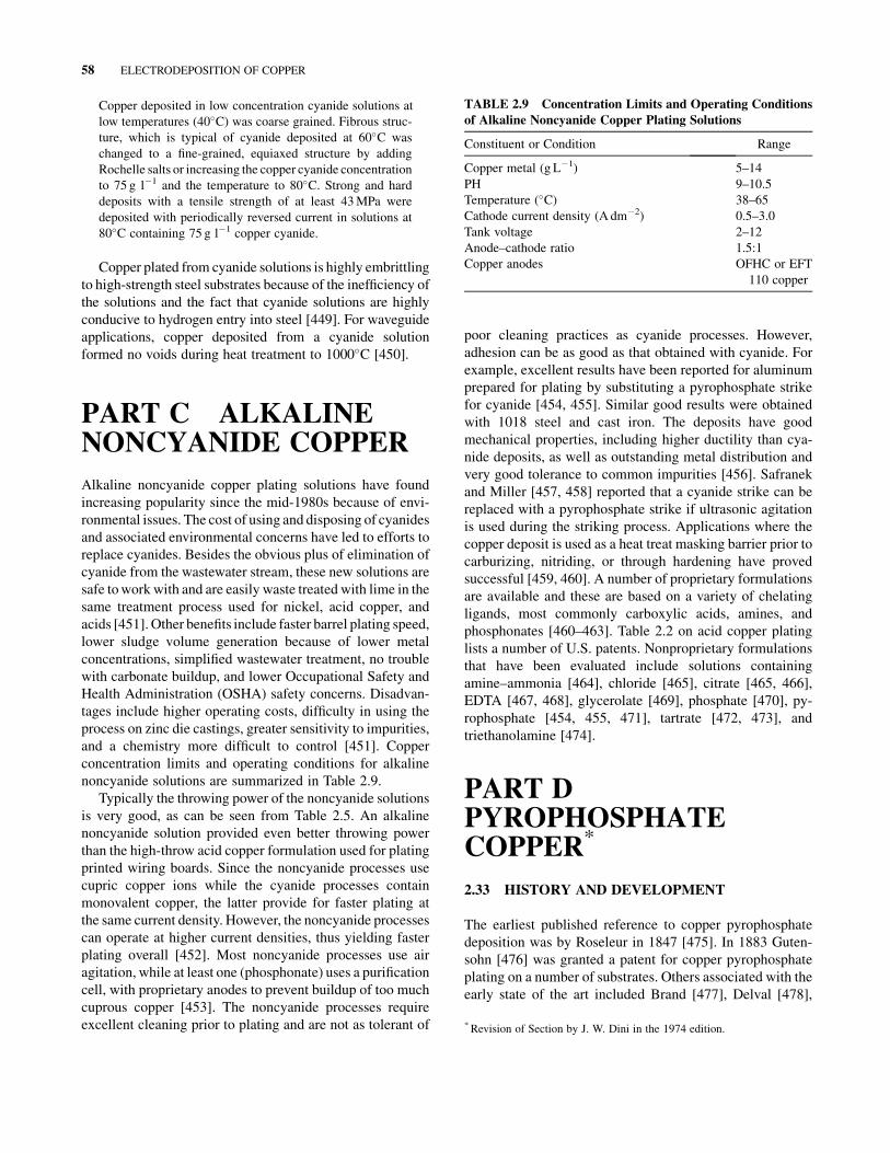
Copper deposited in low concentration cyanide solutions at
low temperatures (40�C) was coarse grained. Fibrous struc-ture, which is typical of cyanide deposited at 60�C was
changed to a fine-grained, equiaxed structure by adding
Rochelle salts or increasing the copper cyanide concentration
to 75 g l�1 and the temperature to 80�C. Strong and hard
deposits with a tensile strength of at least 43MPa were
deposited with periodically reversed current in solutions at
80�C containing 75 g l�1 copper cyanide.
Copper plated from cyanide solutions is highly embrittling
to high-strength steel substrates because of the inefficiency of
the solutions and the fact that cyanide solutions are highly
conducive to hydrogen entry into steel [449]. For waveguide
applications, copper deposited from a cyanide solution
formed no voids during heat treatment to 1000�C [450].
PART C ALKALINENONCYANIDE COPPER
Alkaline noncyanide copper plating solutions have found
increasing popularity since the mid-1980s because of envi-
ronmental issues. The cost of using and disposing of cyanides
and associated environmental concerns have led to efforts to
replace cyanides. Besides the obvious plus of elimination of
cyanide from the wastewater stream, these new solutions are
safe towork with and are easily waste treated with lime in the
same treatment process used for nickel, acid copper, and
acids [451]. Other benefits include faster barrel plating speed,
lower sludge volume generation because of lower metal
concentrations, simplified wastewater treatment, no trouble
with carbonate buildup, and lower Occupational Safety and
Health Administration (OSHA) safety concerns. Disadvan-
tages include higher operating costs, difficulty in using the
process on zinc die castings, greater sensitivity to impurities,
and a chemistry more difficult to control [451]. Copper
concentration limits and operating conditions for alkaline
noncyanide solutions are summarized in Table 2.9.
Typically the throwing power of the noncyanide solutions
is very good, as can be seen from Table 2.5. An alkaline
noncyanide solution provided even better throwing power
than the high-throw acid copper formulation used for plating
printed wiring boards. Since the noncyanide processes use
cupric copper ions while the cyanide processes contain
monovalent copper, the latter provide for faster plating at
the same current density. However, the noncyanide processes
can operate at higher current densities, thus yielding faster
plating overall [452]. Most noncyanide processes use air
agitation, while at least one (phosphonate) uses a purification
cell, with proprietary anodes to prevent buildup of too much
cuprous copper [453]. The noncyanide processes require
excellent cleaning prior to plating and are not as tolerant of
poor cleaning practices as cyanide processes. However,
adhesion can be as good as that obtained with cyanide. For
example, excellent results have been reported for aluminum
prepared for plating by substituting a pyrophosphate strike
for cyanide [454, 455]. Similar good results were obtained
with 1018 steel and cast iron. The deposits have good
mechanical properties, including higher ductility than cya-
nide deposits, as well as outstanding metal distribution and
very good tolerance to common impurities [456]. Safranek
and Miller [457, 458] reported that a cyanide strike can be
replaced with a pyrophosphate strike if ultrasonic agitation
is used during the striking process. Applications where the
copper deposit is used as a heat treat masking barrier prior to
carburizing, nitriding, or through hardening have proved
successful [459, 460]. A number of proprietary formulations
are available and these are based on a variety of chelating
ligands, most commonly carboxylic acids, amines, and
phosphonates [460–463]. Table 2.2 on acid copper plating
lists a number of U.S. patents. Nonproprietary formulations
that have been evaluated include solutions containing
amine–ammonia [464], chloride [465], citrate [465, 466],
EDTA [467, 468], glycerolate [469], phosphate [470], py-
rophosphate [454, 455, 471], tartrate [472, 473], and
triethanolamine [474].
PART DPYROPHOSPHATECOPPER*
2.33 HISTORY AND DEVELOPMENT
The earliest published reference to copper pyrophosphate
deposition was by Roseleur in 1847 [475]. In 1883 Guten-
sohn [476] was granted a patent for copper pyrophosphate
plating on a number of substrates. Others associated with the
early state of the art included Brand [477], Delval [478],
TABLE 2.9 Concentration Limits and Operating Conditions
of Alkaline Noncyanide Copper Plating Solutions
Constituent or Condition Range
Copper metal (g L�1) 5–14
PH 9–10.5
Temperature (�C) 38–65
Cathode current density (A dm�2) 0.5–3.0
Tank voltage 2–12
Anode–cathode ratio 1.5:1
Copper anodes OFHC or EFT
110 copper
* Revision of Section by J. W. Dini in the 1974 edition.
58 ELECTRODEPOSITION OF COPPER

Royer [479], and Regelsberger [480]. Pioneering work by
Stareck [481, 482] led to the development of a commercial
copper pyrophosphate in 1941. The same year Coyle [483]
described the main aspects of the process. Reviews of
copper pyrophosphate plating can be found in [484–490].
2.34 APPLICATIONS
Pyrophosphate copper is used in the production of electro-
formed objects such as waveguides, paint spray masks [491],
helical antennae [492], heat exchangers [493], molds for
making toys [491, 494], and hard, high-strength [495], wear-
resistant [496] deposits. Pyrophosphate deposits are also
used on steel [491, 497, 498] and aluminum parts [499–
504], and in some cases, they serve as a replacement for
cyanide deposits [505, 506]. Other applications include
plating zinc die castings [507, 508] before bright nickel and
chromium plating, as a lubricant for wire deep drawing
operations [485, 491], as a stopoff on steel for selective
hardening operations such as nitriding and carburiz-
ing [485, 509–512], in roll plating [485], in minimizing
hydrogen embrittlement [513, 514], and in the manufacture
of plated steel cord for radial tires and high-pressure
plastic pipes [515, 516]. Pyrophosphate solutions are also
used for plating through holes on printed wiring boards,
although in most cases this application has been replaced by
high-throw acid copper sulfate formulations [490, 517–519].
Use of pyrophosphate processes for automotive decora-
tive plating has been completely eliminated for many
years [520]. Pyrophosphate solutions have been used for
plating on plastics; however, these solutions are considerably
more expensive to make up than high-throw acid copper
formulations [521].
2.35 BASIC CHEMISTRY
The copper pyrophosphate plating solution contains copper
pyrophosphate (Cu2P2O7 � 3H2O), either potassium pyro-
phosphate (K4P2O7) or the corresponding sodium salt
(Na4P2O7), nitrate (NO3), and ammonia (NH3). The pyro-
phosphate salts react in aqueous solution to form alkaline
complex anions, the major complex CuðP2O7Þ 6�2 and also
(Cu2P2O7)2�. The solution is of intermediate stability [522].
Between pH values of 7 and 11, the stability of the complex
anion is evidenced by the slow but sure hydrolysis of
(P2O7)4� to (PO4)
3�. At pH values above 11, Cu(OH)2precipitates; at pHvalues noticeably below 7 eitherCuH2P2O7
or Cu2P2O7 precipitates. Acidification below pH 7 converts
the (P2O7)4� to either (H2P2O7)
2� or (HPO4)2� and thus
destroys the complex anion [523]. Additional information
on the chemistry of copper pyrophosphate complexesmay be
found in [486–488, 524–534].
2.36 CONSTITUENTS
2.36.1 Copper and Pyrophosphate
Typical formulations are included in Table 2.10. The copper
and pyrophosphate contents of the plating solution are
critical in terms of the ratio of one to the other. To promote
anode corrosion and to increase electrical conductivity, the
solution must contain excess complexing compound. Al-
though either may be used, potassium pyrophosphate is
preferred over the sodium salt because it is more soluble,
and a potassium solution has a higher electrical conductivity
because of the higher mobility of potassium ions.
2.36.2 Nitrate
The presence of a nitrate results in a highermaximum current
density because, especially at current densities above
3.2A dm2, the nitrate ion reduces cathode polarization by
acting as a hydrogen acceptor according to the equation [485]
NO �3 þ 10Hþ þ 8e ¼ NH þ
4 þ 3H2O
As the solution is used extensively, reduction of the nitrate
ion also leads to a buildup of nitrite [535].
2.36.3 Ammonia
A small amount of ammonia is used to producemore uniform
and lustrous deposits and to improve anode corrosion. Excess
ammonia can cause cuprous oxide to form and this can hinder
adhesion [522].
Because ammonia evaporates from the plating solution,
it is usually added daily in quantities either dependent on the
size of the tank, for example, 140 g of ammonium hydroxide
per square meter of exposed surface per day [536], or as
determined by chemical analysis of the solution. In some
installations, gaseous ammonia is used [537]. Kojima [538]
disclosed that ammonia consumption increasedwith increas-
ing temperature, pH, agitation, and ammonia content in the
solution, while current had little effect on consumption.
2.36.4 Orthophosphate
Orthophosphate formed by the hydrolysis of pyrophosphate
is beneficial in that it promotes anode corrosion and acts as
TABLE 2.10 Optimum Range of Solution Constituents
Analytical Constitutent Composition (g L�1)
Copper, Cu2þ 22–38
Pyrophosphate, (P2O7)4� 150–250
Nitrate, NO�3 5–10
Ammonia, NH3 1–3
Orthophosphate, (HPO4)2� No greater than 113
Organic additives As required
CONSTITUENTS 59

a buffer. At all concentrations it affects the properties of the
plating solutions and deposits. Increasing orthophosphate
concentration decreases the throwing power and efficiency
of the solution and causes a reduction in the ductility of
deposits [539].
Low pH (less than 7), increasing P2O7 concentration, high
P2O7–Cu ratio, high temperatures (greater than 60�C) in theplating solution or heat exchanger, or local overheating will
cause orthophosphate to build up. Orthophosphate cannot
be removed chemically from a pyrophosphate solution. The
concentration can be reduced only by either discarding the
solution altogether or by diluting and rebuilding it.
2.36.5 Additives
Additives have more of an influence on deposit properties
than anyother plating variable, aswill be shown in the section
on properties and structure. When used at controlled, limited
concentrations, organic additives refine the grain structure,
provide desired tensile and ductility properties, impart level-
ing characteristics to the plating solution, and act as bright-
eners. However, decomposition products from an excessive
additive concentration can cause brittle copper deposits.
Thus, for optimum quality deposits, no more additive should
be added to a solution than is necessary to replace losses by
consumption.
Organic additives covered in the patent literature as
brighteners include mercaptothiadiazoles [540–550], mer-
captothiazoles [551–556], mercaptobenzimidazole [557],
and pyrimidines [555, 558, 559]. Other organic and inorganic
materials, such as glycerol [560, 561], triethanolamine
[560, 561], trioxyglutaric acid [525, 562], diphenylamine
sulfonic acid [561], naphthalene disulfonic acid [563], gel-
atin, bakers yeast, casein, glycocoll [564], hydroxyethylcel-
lulose [565], sodium selenite [525, 559], sodium sulfite
[560, 561], Rochelle salt, sodium thiosulfate, potassium
bromide [561], and the chlorides of As, Bi, Fe, Cr, Sn, Zn,
Cd, Pb [482, 563], and alkali metals have been used as
brighteners. Additions of small amounts of lead are reported
to improve plating properties [566, 567]. Organic acids such
as oxalic, lactic, tartaric, malic, and citric or their ammonium
or alkali salts also produce some brightening [482].
2.36.6 Operating Conditions
A copper pyrophosphate plating solution may be operated
over a relatively wide range of conditions. The optimum
range, similar to that given by Couch and Stareck [568], is
shown in Table 2.11.
2.36.7 Pyrophosphate–Copper Ratio
The copper pyrophosphate solution is analyzed for both
copper and pyrophosphate, and it is therefore convenient to
describe the solution in terms of the ratio between these
constituents. For optimum plating, the weight ratio of pyro-
phosphate to copper should be kept in the range 7:1–8:1.
Ratios of 8.5:1 or higher promote formation of orthophos-
phate and therebydecrease the bright plating range.Operation
with a ratio of less than 7:1 tends to produce a rough-surfaced
plate and renders the solution unstable.
2.36.8 pH
The optimum solution pH is in the range of 8–9. As discussed
earlier, a pH outside this range results in hydrolysis of
pyrophosphate to orthophosphate or the formation of pre-
cipitates. Also, if the pH is too high, both anode corrosion and
operating current density range decrease. Radin [569] states
that a pyrophosphate solution will operate acceptably even at
pH values as high as 9.3 provided the copper concentration
exceeds 26 g L�1.When a solution is operated at this high pH,
the tendency toward roughness can be eliminated by increas-
ing the P2O7–Cu ratio. In practice, a pH of 7–9 is easily
maintained because at this pH both anode and cathode
efficiencies are virtually 100%. Clearly, there is no chemical
breakdown of the constituents, and the solution is highly
buffered. When adjustments must be made, pyrophosphoric
acid is used for lowering pH and potassium hydroxide for
raising it.
2.36.9 Temperature
The solution is usually operated between 50 and 60�C.Temperatures greater than 60�C can lead to rapid formation
of orthophosphate.
2.36.10 Current Density
Cathode current density is a function of the temperature and
agitation of the plating solution. However, under standard
operating conditions, a current density of 1–9A dm�2 is
appropriate. The anode current density is fairly critical, and
it should be kept between 2 and 4A dm�2. At too high
an anode current density, an insoluble oxide tends to form.
The operating current density range may be increased by
TABLE 2.11 Optimum Operating Conditions
P2O7–Cu ratio 7.0:1–8.0:1
pH 8.0–8.8
Temperature, �C 50–60
Cathode current density, A dm�2 1–8
Anode and cathode efficiency, % 100
Anode–cathode ratio 1:1–2:1
Agitation 1–1.5m3/(min) (m�2)
of surface
60 ELECTRODEPOSITION OF COPPER

ultrasonics, by current interruption or reversal, and by in-
creased metal concentration.
2.36.11 Agitation
Copper pyrophosphate solutions are among those thatmust be
most vigorously agitated. Without sufficient agitation, a
brownishdeposit is obtained, and theoperatingcurrentdensity
range is drastically lowered. A solution can be continuously
agitated by either one or a combination of three methods: air,
mechanical movement of the cathode, or ultrasonics. When
air agitation is used, the air should be supplied by a low-
pressure blower because compressed air can contain oil.
Gurylev et al. [570] claimed that ultrasonic agitation
reduces anode and cathode polarization and permits a
4–4.5 times increase in the deposition rate over that obtained
with intensive mechanical agitation. The combination of
ultrasonics and periodic reverse current increased current
efficiency and allowable anode current density. Rutter
et al. [571] reported that the use of ultrasonics resulted in
improved adhesion and a denser deposit. Safranek and
Miller [507, 508] and others who have plated over zinc die
castings showed that ultrasonic agitation of copper pyro-
phosphate solutions displaced air or hydrogen from blind
pockets and resulted in more uniform deposits than could be
obtained with copper cyanide strikes. Uspenskii and Schlu-
ger [572] investigated pH variations in an ultrasonic field
and Trofinov and Galushko [573] polarization characteris-
tics. Trofinov [574] concluded that metal distribution from a
copper pyrophosphate electrolyte could not be influenced
much by an ultrasonic field. Vasudevan et al, [575] reported
an improvement in both anodic and cathodic current effi-
ciencies under ultrasonic agitation but no change in hardness
of the deposit.
2.36.12 Equipment
The equipment—a tank, heater, and filter—is similar to that
used for bright nickel plating.A steel tank coatedwith rubber,
Koroseal (Trademark: B. F. Goodrich Co.), PVC, or a
plastisol is suitable, although rubber linings should be lea-
ched before usewith a dilute solution of potassium hydroxide
to remove all alkali soluble matter that can contaminate the
plating solution. For heating the solution, either steam heat-
ing coils or electric immersion heaters made of stainless steel
or Duriron may be used. Continuous filtration helps prevent
rough deposits. The filter should be constructed of stainless
steel, rubber, or PVC-lined steel or cast iron.
2.36.13 Anodes
OFHC anodes are the best available; however, electrolytic
sheet and rolled electrolytic copper anodes are also
satisfactory. Cast anodes of good purity can also be used,
but they should be free of impurities such as lead, nickel,
silver, and tin because these tend to promote deposit rough-
ness. Anode bags are not usually used; they are not needed
and can restrict circulation of the plating solution around
the anode and cause polarization. Anodes can be left in the
solution when it is not being used since they do not dissolve
in the absence of applied current.
2.37 MAINTENANCE AND CONTROL
2.37.1 Analysis
For the analytical determination of copper, pyrophosphate,
and orthophosphate, the simplest procedure is that of
Konishi [576], where all three constituents are determined
by titration with EDTA. Copper can also be determined
electrolytically [577] or by titration by the iodine–thiosulfate
method [577–579], pyrophosphate by titration with standard
alkali [577–579], and orthophosphate gravimetrically
[578, 579] or colorimetrically [580]. Ammonia is analyzed
by distillation and adsorption in standard acid [577, 579] or
by cyclic voltammetric stripping (CVS) [581]. Tench and
Ogden and their circle of researchers have pioneered in the
use of CVS, particularly for controlling additives and con-
taminants in copper plating solutions for printedwiring board
production. Their work with pyrophosphate solutions is
covered in references [542–549] and reviewed in detail
in [582]. Tam and co-workers [534, 535] also used CVS to
study the effects of all constituents on cathodic and anodic
reactions.
2.37.2 Impurities and Purification
Cyanide, oil, lead, decomposition products of the organic
additives, residues from photoresists and solvents used in
circuit development, epoxy laminate residues, excess ortho-
phosphate, and substances leached from plating tanks are the
impuritiesmost often encountered in a copper pyrophosphate
plating solution. These impurities cause streaked, dull de-
posits and also lower the effective current density range.
Precautionary methods will prevent these materials from
entering the solution. Thorough rinsing, when copper cya-
nide striking is used, will prevent cyanide contamination; a
clean air line for solution agitation will prevent oil contam-
ination; and avoiding the use of lead coils, lining, fittings, or
filters will prevent lead contamination.
Cyanide, which can be detected by a copper benzidine
test [583], can be removed by treatment with either 1.25mL
L�1 of 30% H2O2 or 0.1–0.2 g L�1 potassium permanganate
followed by treatment with activated carbon. The tendency
toward streaked, nonuniform pyrophosphate deposits due to
residual traces of cyanide left on the surface after copper
cyanide striking can beminimized by brief cathodic treatment
in a solution of potassium pyrophosphate before it is placed
MAINTENANCE AND CONTROL 61

in the plating solution. Oil can be removed by treating the
solution with 2.5–6 g L�1 of activated carbon at 55�C for
4–8 h. Low-current-density electrolysis will remove lead.
Copper pyrophosphate solutions are quite tolerant of
metallic contamination because many metals besides copper
form complexes with the pyrophosphate ion and remain in
solution. For example, no harmful effects have been reported
from zinc whichmay be introduced when the solution is used
to plate zinc die castings. It has been recommended, however,
that a high P2O7/Cu ratio (preferably 7.5: 1) be maintained
under this circumstance so as to allow some excess pyro-
phosphate for complexing with the contaminant. Phosphorus
included in the deposit was reported to influence external
appearance, microhardness, and microstructure [584]. Iron
and lead can alter deposit morphology and concentrations
below 200 and 1000 ppm, respectively, are recom-
mended [516]. Chloride ion, which is known to affect anode
reactions, can be tolerated at concentrations lower than 0.1M
with vigorous agitation of the solution [515].
Organic contaminants, besides reducing deposit ductility
and strength, can also cause loss of throwing power and
irregular deposition. The contamination can come from
decomposition products fromorganic additives, air agitation,
leaching of photoresists, and the carbon used for removing
contaminants. Rothschild et al. [585] provide an excellent
review on carbon treating of pyrophosphate solutions for
keeping them free of organic contaminants and recommend
the use of Hull cell tests to determine the effectiveness of
treatment. In some cases an activated carbon treatment alone
is not sufficient purification. To ensure removal of the
decomposition products, it is best to carbon treat the solution,
H2O2 treat, and then carbon treat again. The carbon should be
plating grade and sulfur free.
Cyclic voltammetric stripping analysis is an excellent
means for detecting a wide range of contaminants in addition
to organic additives in pyrophosphate solutions. Excellent
correlation has been obtained between the measured con-
taminant level and plating problems normally attributed to
solution contamination such as poor solder adhesion and low
deposit ductility [542, 544, 545, 548].
Wastepyrophosphate solutions aredifficult to treat because
of ammonia in the solutions and also the complexes that are
formed [586].Wastes require low-pHhydrolysis toorthophos-
phate followed by precipitation of the heavy metals [488].
2.38 STRUCTURE AND PROPERTIES
The best source for property data is Safranek’s treatise on
properties of electrodeposits [587]. Another comprehensive
reference is that of Lamb et al. [588], who provide data on
Young’smodulus, fatigue strength, effects of cold rolling and
annealing on mechanical properties, tensile and elongation
data for temperatures from�78 to 325�C, thermal expansion,
texture analysis, and gas content for solutions containing no
addition agents.
Copper pyrophosphate deposits show tensile strength
variations from 27 to 70 kg mm�2, yield strengths from 14
to 36 kg mm�2, hardness from 83 to 250 kg mm�2, and
elongations from 1 to 39%. Several investigators have related
these variables to solution content and operating variables
with additive concentration being the most important vari-
able [495, 547, 589–595].
Optimum ductility has been obtained by using solutions
free of organic additives [588]. In some cases, continuous
filtration is also used [589, 596]. High-purity, high-quality
deposits have been produced on internal walls of colliders
in beam tubes by using multistage purification and pulsed
reverse current in solutions with no additives [597, 598].
A comparison of recrystallization temperature for elec-
trodeposited pyrophosphate copper and wrought copper with
various degrees of cold work suggests that the electrodepos-
ited copper exhibits behavior expected of 100% cold-worked
material [592]. Malone [599] reported that pyrophosphate
copper electrolytes were capable of producing deposits with
excellent mechanical properties. However, he cautioned that
the pyrophosphate electrolyte is very difficult to control and
maintain in comparison with the acid sulfate solution, and
producing deposits consistently within a specific range may
prove difficult unless the electroplater has considerable
experience with the pyrophosphate solution and the many
pecularities associated with it. The influence of pH, temper-
ature, agitation, and current density on throwing power and
efficiency can be found in [600].
2.39 PLATING OF PRINTED WIRING BOARDS
The 1974 edition of this book [484] devoted a section to this
topic in the chapter on copper pyrophosphate. Around the
time of publication of that volume, high-throwing-power
acid copper sulfate solutions were developed [601]. Today
these solutions are used instead of pyrophosphate for most
printed wiring board applications, except in some military
and special applications [490]. It is estimated that greater
than 95% of all printed wiring boards today are plated in
acid copper sulfate solutions [518]; this is discussed in more
detail in Section 2.12. A good review of present practice with
pyrophosphate plating of printed wiring boards can be found
in [490].
PART E COPPERCOMPOSITES
Present-day structural materials have two major shortcom-
ings: loss of strength at elevated temperatures and relatively
62 ELECTRODEPOSITION OF COPPER

low elastic moduli [602]. One way to solve these problems is
in strengthening materials by incorporating high-strength
and high-modulus particles, fibers, or continuous filaments
in a metal matrix. The major disadvantages of present
methods (internal oxidation, powder metallurgy, high-pres-
sure bonding, and infiltration) in producing dispersion-
strengthened and fiber-reinforced composites are the high
process temperatures and pressures required. Degradation
of the fibers due to handling and difficulties encountered
in machining the finished composite structure are also
concerns.
A less common method of producing these composites is
electrodeposition. There is no requirement in electrodepo-
sition for high temperatures that can damage the fibers. The
strengthening of electrodeposits can be accomplished by
the encapsulation of inert particles, fibers (whiskers), or
filaments during plating to produce high-performance coat-
ings [602–604]. Two terms commonly used to refer to use of
electrodeposition to produce composite materials are com-
posite plating and electrocomposites. Electrodeposition of
Copper and nickel are the two plating processes most com-
monly used to produce composites; copper will be covered in
this section. Reviews on composite plating can be found
in [602–610].
Copper compositematerials have typically been produced
in sulfate solutions, although acid fluoborate and alkaline
cyanide solutions have also been used. Particles that have
been codeposited with copper include alumina, barium sul-
fate, borides, carbides, carborundum, corundum, graphite,
molybdenum disulfide, polystyrene, phosphorus, polytetra-
fluoroethylene (PTFE), quartz, titania, tungsten disulfide,
and zirconium oxide. Mechanical or ultrasonic agitation was
required to uniformly disperse the particles, which ranged
from 50 to 200 gL�1, in the solution.
A variety of techniques can be used for codeposition of
particles. Namely occlusion plating particles are allowed to
codeposit on the cathode surface while some intermittent
vigorous mechanical stirring of the plating solution is ap-
plied [609], sediment codeposition particles are allowed to
sediment on a flat cathode as electrolysis proceeds and are
only occasionally agitated [611–614], and composite plating
particles are deposited on a vertical cathode [609]. Particles
are kept in suspension by either mechanical or chemical
means. Suspension bymechanical means is accomplished by
use of a vibrating perforated bottom plate or by the use of air
agitation. Suspension by chemical means typically requires
the addition of appropriate surfactants to the plating solution.
The optimum conditions for preparing particle suspen-
sions and codepositing a designated volume fraction of
uniformly dispersed inert particles have not been firmly
established. Most of the literature data have been derived
empirically. Particle diameters have ranged from 0.02 to
100 mm. Quantities dispersed in solution have varied from 50
to 200 gL�1 [604]. Wetting agents, monovalent cations and
aliphatic amines absorbed on particle surfaces, promoted
encapsulation and improved dispersion [609, 615, 616]. Par-
ticle encapsulation was less during operation of a copper
sulfate solution, in comparison with the amounts reported for
code position in cyanide solutions [604, 609, 615–617].
2.40 ALUMINA
The copper–alumina system has been investigated by many
researchers [604, 605, 607, 618–641]. Both a-alumina
(0.3–1.0 mm) and rutile titania (0.3 mm) were readily co-
deposited with copper in an acid solution, but c-alumina
(0.2 mm) and anatase titania were not. Calcining (20 h at
1125�C) promoted the codeposition of c-alumina particles in
copper [618]. This effectively transformed the surface of cparticles into an a structure, as verified by X-ray studies.
Lakshminarayanan et al. [619–621] concluded that a- andc-alumina could be codeposited provided that the plating
solution was free of chloride. By contrast, Roos et al. [622]
reported that both c- and a-alumina could be codeposhed in
an acid sulfate solution with or without the presence of
chloride ions in the solution. However, under identical con-
ditions, much smaller quantities of c-alumina were code-
posited as compared with a-alumina.
With pulsed or periodically reversed current, increasing
the current density increased the alumina content of
copper [623, 624]. Ultrasonic agitation reduced agglomera-
tion, improved particle distribution, and improved the strength
retention of copper–alumina composites [625].
2.41 PROPERTIES
Lakshminarayanan et al. [620] reported that codeposition of
1.2%, by volume, of 0.03 mm c-alumina increased the yield
and ultimate tensile strengths of copper from97 and 197MPa
to 128 and 246MPa, respectively, while elongation was
reduced from 32 to 20%. An increase in the alumina content
to 2.4% increased the yield and tensile strengths to 217 and
345, respectively, while the elongation was 15% [620].
A fairly high yield strength of 50MPa was retained after
the copper–alumina composites were annealed at 420�C.Stankovic and Gojo [641] noted that tensile strength in-
creased to about 290MPa with increasing alumina particle
content. Further increases in the particle content did not
affect the tensile strength significantly. As regards electrical
resistivity, a 2.2% alumina composite exhibited a moderate
increase over pure copper (1.86 vs. 1.72 mV-cm) [620].
Abrasive wear was reduced 83–85% by codepositing 5.5
or 7.3% of carborundum particles [642]. Based on friction
measurements, copper–graphite composites appeared to be
the best self-lubricating coating when compared with com-
posites containing molybdenum disulfide or PTFE parti-
cles [643]. Silicon carbide codeposited particles provided
PROPERTIES 63

a high hardness which was retained up to 900�C. Abrasionand oxidation resistance also improved as a result of inclu-
sion of silicon carbide [605]. A summary on property data
can be found in reference [606].
2.42 MECHANISM
A two-step mechanism was proposed by Guglielmi [644] in
which the combined effect of adsorption and electrophoretic
attraction is held responsible for the encapsulation of par-
ticipate matter in a growing electrodeposited layer. The
validity of Guglielmi’s model has been verified for different
codeposition systems, including copper with alumina from
acidic sulfate solutions, with and without the addition of
thallium. However, Guglielmi’s model does not allow pre-
diction of the manner in which process parameters such as
size, type, and pretreatment of the particles, composition,
temperature, and pH of the plating solution affect the elec-
trolytic codeposition [609].
Foster and Kariapper [627] proposed a mathematical
model in 1974 that could describe the effect of hydrody-
namics on codeposition, but only a limited amount of quan-
titative work has been done to prove its validity. Snaith and
Groves [645–647] also reported on mechanisms.
In 1987 Celis et al. [639] proposed a model that contains
measurable parameters so that the prediction of the amount of
codeposited particles for a given system becomes feasible.
As described, “This mathematical model is developed on the
basis of two fundamental postulates related to themechanism
of codeposition, namely: 1—an adsorbed layer of ionic
species is created around particles at the time these particles
are added to the plating solution or pretreated in ionic
solutions and 2—the reduction of some of these adsorbed
ionic species is required for the incorporation of particles in
the metallic matrix” [639].
Figure 2.3 shows that the particle has to proceed through
five stages: (1) the adsorption of ionic species upon the
particle, (2) the movement of the particle by convection
toward the hydrodynamic boundary layer at the cathode,
(3) the diffusion of the particle through the diffusion double
layer, (4) the adsorption of the particle with its adsorbed
ionic cloud at the cathode surface, and (5) the reduction of
some adsorbed ionic species by which the particle becomes
irreversibly incorporated in the metal matrix. The model
has been demonstrated to be valid for the codeposition of
alumina particles with copper from acid copper sulfate
plating solutions [609, 639].
2.43 CONTINUOUS FIBER-REINFORCED
COMPOSITES
Acid copper solutions have been used in fabricating fiber-
reinforcing metal composites. In these processes, simple salt
solutions work satisfactorily, whereas highly complexed
solutions such as cyanide do not [648]. Continuous, unidi-
rectional filament-reinforced electrocomposites that have
been produced include 25 mm tungsten in copper and 100 mmboron in copper [604]. A composite containing 40% volume
of tungsten filaments, produced by continuously winding
tungsten wire on the cathode during copper deposition,
exhibited a tensile strength of 1325MPa [649].
Graphite–copper composite panels have been fabricated
by weaving copper-coated graphite fibers into a fabric and
then consolidating by hot pressing. This offers a potential
technique for low-cost processing of metal matrix composite
electronic heat sinks [650]. Carbon fibers are continuously
coated with copper in a pyrophosphate–HEDP (hydro-
xyethylidene diphosphonic acid) electrolyte [651].
PART FCOPPER PLATING INMICROELECTRONICS
New applications are opening up for copper conductors
in microelectronics, microelectromechanical systems
(MEMSs), and nanotechnology [652]. Incorporating mate-
rial into three-dimensional geometries is a strength of elec-
trodeposition. A major success has been the replacement of
aluminum and its alloys by copper for ultra-large-scale
integration (ULSI) interconnects [653]. The deep reservoir
of copper plating knowledge has enabled a natural and rapid
emergence of process technology. Implementation of copper
FIGURE 2.3 The five stages in the codeposition of a particle.
(From Celis et al. [639]. Reproduced by permission of the Elec-
trochemical Society, Inc.)
64 ELECTRODEPOSITION OF COPPER

results in a 40% lower wire resistance, 20–30% anticipated
boost in chip performance, improvements in wire reliability,
and 10–15% lower chip cost.
Moore’s law formicroelectronics states that the density of
elements on integrated circuits will increase steadily as
predictable process improvements are implemented. As stat-
ed today, the number of transistors that can be placed on an
integrated circuit with commercial processes doubles ap-
proximately every three years. As feature size reached sub-
micrometer level, the drawbacks of aluminum interconnects
became apparent, notably the high electrical resistance. The
microelectronics industry identified copper as a likely inter-
connect replacement material and began to incorporate this
change in plans such as the SEMATECH Roadmap [653].
SEMATECH creates its Roadmap with targets such as the
required half-pitch of dynamic random-access memory
(DRAM) designs. As feature size onULSI devices decreases,
this minimum size requirement decreases. The industry is
currently operating at the 45-nm SEMATECH Roadmap
node. When a new feature size node becomes the norm,
major changes and investment are required for new micro-
fabrication facilities. Programs are in progress to prepare
for the coming shift to the 32-nm node. And a further shift
to the 22-nm minimum-size node is projected within six to
eight years.
In 1998, IBM announced its successful development of
copper electroplating technology for fabrication of chip
interconnect structures [654, 655]. The challenge was to fill
trenches and vias within the silicon chip without creating
voids or seams and without degrading the circuit materials
and patterns. IBM found that it could fill submicrometer-size
features completely, that is, without voids, if the plating
solution contained an appropriate mixture of additives. They
termed this phenomenon “superfilling” and named the pro-
cess “damascene copper,” after the classic art form of metal
inlay. The silicon substrate is first configuredwith its trenches
and vias. Then an insulating coating is applied followed by
a seed layer of copper. At this point, copper metal is added
by electrodeposition to fill the trenches and the vias, com-
pleting the interconnect pattern. Finally, excess over plated
copper is removed from thewafer surface. Filling of trenches
only is termed single damascene, and simultaneous filling
of trenches and vias is termed dual damascene.
It was understood that success with superconformal fea-
ture filling depended heavily on the additive mix, and their
relative diffusion/adsorption characteristics, in the plating
solution. Copper electrodeposition had been well studied, so
there was a solid base from which to build and refine the
process. Other tools were also available, such as controlled
agitation and pulse reversal deposition. Projections based
only on today’s technology for depositing seed layers and for
damascene filling indicate that copper superconformal filling
will be the preferred practice down to at least the 22-nm node
on the SEMATECH Roadmap [656].
Understanding of the phenomena operating was incom-
plete during the early development of the copper damascene
process [657]. A National Institute for Standards and
Technology (NIST) group determined that the superconfor-
mal filling of trenches and vias by electrodeposited copper
involved competitive interaction between additive species
that accelerate and inhibit deposition. The accelerator ad-
sorbs on the cavity wall and, as electrodeposition proceeds,
the feature diameter generally decreases. Current under-
standing suggests that the surface density of accelerator
increases with decreasing feature diameter, leading to an
increase in deposition. This occurs as the base of trenches and
vias, becoming the basis for bottom-up filling. Normally,
in the absence of additives, a cavity in a surface would be
capped with overgrowing deposit, trapping amicrocavity—a
situation that must be avoided with ULSI fabrication.
Additives and basic ingredients of acidic copper plating
solutions fall into one of the following categories:
. Copper sulfate provides the source of copper ions.
. Sulfuric acid gives conductivity and induces soluble
anode corrosion.
. Chloride is synergistic with organic additives in the
brightening and leveling.
. The brightener, or accelerator, typically contains low-
molecular-weight sulfur and a second atom of high
polarity and/or ionic character. Its function is to refine
the grain structure in normal copper electrodeposition.
Typical brighteners include thiourea, disulfides, thio-
carbamates, and thiocarboxylic acid amides.
. Inhibitors convert an unevenly distributed stationary
cathode diffusion layer into a more evenly distributed
layer and reduce the variation in copper deposit thick-
ness across the surface. Examples include high-molec-
ular-weight polyether compounds, surfactants, and
polyoxyalkylene glycols.
. The polar leveler slows down the charge transfer of
copper ions to copper metal, thus slowing the plating
rate in those areas considered high current density.
NIST developed a quantitative process model on this
basis—curvature-enhanced accelerator coverage (CEAC)—
that has guided development [658]. The basic idea is that
(a) the growth velocity of the infilling copper is proportional
to the local accelerator, or catalyst, coverage, and (b) the
catalyst remains segregated at themetal–electrolyte interface
during metal deposition. This leads to catalyst enrichment
on advancing concave surfaces and catalyst dilution
on advancing convex surfaces. The result is the desired
bottom-up filling of submicrometer features in the integrated
circuit. The NIST group validated the CEAC model with
an archetypical additive package of chloride, PEG, and a
sulfide such as 3-mercapto-1-propanesulfonate (MPSA) or
CONTINUOUS FIBER-REINFORCED COMPOSITES 65

[Na2(SO3(CH2)3S)2] (SPS). In acidified copper sulfate solu-
tion, inhibition is provided by interaction between PEG–C1
and the copper surface. Acceleration is associated with the
competitive adsorption of the sulfide or its derivatives.
Damascene copper has the tendency to form bumps above
filled features, termed overshoot. The NIST group recently
reported on using a cationic surfactant additive to inhibit
this undesirable copper overplate [659]. The surfactant is
included at a level that permits the desired SPS-derived bot-
tom-up filling but quenches the SPS mechanism as filling is
completed. NIST has published an extensive coverage of the
nature and modeling of superconformal film growth [660].
As damascene processing is used for ULSI designs with
ever-smaller features, the copper grain size becomes a factor.
Pulse current and periodic pulse reverse current tend to give
improved distribution of copper on high-aspect-ratio surfaces
when compared to direct current plating. And copper grain
size tends to decrease with increasing pulse frequency [661].
Vereecken and IBM colleagues have shed more light on
the mechanism by which damascene additives interact with
the cuprous and cupric ions to create the balance of accel-
eration and inhibition [662]. Kim and NIST colleagues also
applied electroanalytical methods to probe the mecha-
nism [663]. They conclude that inhibiting additives limit
access of cupric ions to the copper surface. They further
determined that cationic surfactant additives deactivate SPS
(sulfur-containing) accelerator additive by tying up the an-
ionic group. The combined process can be optimized to
enable superfilling to be sustained while simultaneously
attenuating overfill bump formation.
As of 2004, over 200 damascene electroplating systems
were in use in semiconductor fabrication worldwide [664].
Wafers are typically held face down in the electrolyte and
rotated during electrodeposition. Superconformal filling of
via holes and trenches and production of void-free vias and
lines is largely dependent on the action of organic additives in
solution. The organic additive concentrations must be kept
within a process window. IBM accomplishes this with a
combination of monitoring and makeup of solution. They
consider analysis by cyclic voltammetry analysis to be one
option for tracking bath composition [665]. Organic additives
added to copper electroplating baths typically include sup-
pressor (polymers such as PEGs), accelerators (sulfur-con-
taining compounds), and levelers (secondary suppressors).
Organic components are consumed during the actual damos-
cene processing step. Innovators continue to identify chem-
istries and added surface treatments to suppress void forma-
tion and reduce stress in the filled features and vias [666, 667].
The IBM announcement [654, 655] included an initial
model to guide future process development and control.
NIST developed further insights on bump suppressions using
its CEAC model [668]. And the Alkire University of Illinois
group has contributed a series of improvements to the algo-
rithms and computation methods [669–673].
Electrochemical phenomena such as copper damascene
are embraced as a challenge of current nanotechnology
research because their behavior results from linked interac-
tions spanning many length scales. At one extreme is the
molecular scale of adsorbed additives and copper nanostruc-
tures. At the other extreme is the macroscale of the silicon
wafer and its features. Multiscale simulation has become
a priority for all fields of science and engineering [668, 669].
As a result of increased investment and sharing, computing
power and algorithms are becoming ever more powerful.
The improvement in scientific understanding and modeling
capability will continue. Computing is no longer an issue.
The research focus is on developing improved models and
algorithms, which can come from related fields as well as
electrochemical science and engineering.
REFERENCES
1. L. W. Flott, Metal Finish., 94, 55 (Mar. 1996).
2. R. Sard, in Encyclopedia of Materials Science and Engineer-
ing, Vol. 2, M. B. Bever, Ed., Wiley, New York, 1986.
2a. P. C. Andricacos, Interface, 7, 23 (Spring 1998).
2b. P. C. Andricacos, Interface, 8, 32 (Spring 1998).
3. W. H. Safranek, The Properties of Electrodeposited Metals
and Alloys, 2nd ed., American Electroplaters and Surface
Finishers Soc., Orlando, FL, 1986.
4. D. L. Snyder, Met. Finish., 89, 37 (Apr. 1991).
5. F. Passal, Plating, 46, 628 (1959).
6. F. A. Lowenheim, Modern Electroplating, 3rd ed., Wiley,
New York, 1974.
7. M. Carano, Electronics, 32 (3), 29 (Mar. 1986).
8. J. F. D’Amico and M. A. De Angelo, J. Electrochem. Soc.,
123, 478 (1976).
9. A. Smee, Elements of Electrometallurgy, 2nd ed., Longmans,
Green, London, 1843.
10. G. R. Strickland, Prod. Finish. (London), 24, 24 (Sept. 1971).
11. G. C. Van Tilburg, Plating Surf. Finish., 71, 78, (Apr. 1984).
12. W. De la Rue, London Edinborough Philos. Mag., 9, 484
(1836).
13. W. H. Safranek, F. B. Dahle, and C. L. Faust, Plating, 35, 39
(1948).
14. Langbein, Electrochem. Metall., 3, 310 (1903).
15. Beadle, Electrochem. Metall., 1, 163 (1901).
16. E. F. Kern, Trans. Am. Electrochem. Soc., 15, 441 (1909).
17. E. F. Kern, U.S. Patent 946,903 (1910).
18. C. G. Fink and C. Y. Wong, Trans. Electrochem. Soc., 63, 65
(1933).
19. A. I. Levin, S. M. Scherbakov, F. A. Zorin, V. M. Svitskii, and
R. A. Gokhina, J. Appl. Chem. (USSR), 13, 686 (1940);Chem.
Abstr., 35, 3536.
20. A. I. Levin, J. Appl. Chem. (USSR), 14, 78; 1941; Chem.
Abstr., 36, 972.
66 ELECTRODEPOSITION OF COPPER

21. N. P.Diev andA. J. Loshkarev, J. Appl. Chem. (USSR), 12, 585
(1939); Chem. Abstr., 33, 8504.
22. D. C. Gernes, G. A. Lorenz, and G. H. Montillon, Trans.
Electrochem. Soc., 77, 177 (1940).
23. J. R. Stack, U.S. Patent 2,294,053 (1942)
24. M. Schlotter, J. Korpiun, and W. Nurmeister, Z. Metall., 25,
107 (1933).
25. D. Thomas and J. C. Silva, J. Electrochem. Soc., 143, 458
(1996).
26. C. Struyk and A. E. Carlson,Mon. Rev. Am. Electroplat. Soc.,
33, 923 (1946).
27. K. S.Willson, A. H. DuRose, andD. G. Ellis,Plating, 35, 252,
304 (1948).
28. C. L. Faust, B. Agruss, E. L. Combs, and W. A. Pruell, Mon.
Rev. Am. Electroplat. Soc., 34, 541, 709 (1947).
29. W. A. Proell, U. S. Patent 2,525,943 (1950).
30. L. Cambi and R. Piontelli, Rend. 1st. Lombardo Sci. Lett.,
72 (1), 128 (1939); Chem Abstr., 34, 4995 (1940).
31. S. Venkatachalam and T. L. Rama Char, Electroplat. Met.
Finish., 14, 3 (1961).
32. J. E. Stareck and F. Passal, U. S. Patent 2,383,895 1945.
33. C. B. F. Young, Met. Finish., 47, 56 (Nov. 1949).
34. D. Uceda, T. O’Keefe, and E. Cole, J. Electrochem. Soc., 137,
1397 (1990).
35. I. Hoshino and T. Fumoto, Japanese Patent 5306 (1955).
36. K. Hosokawa and T. Inui, Kinzoku Hyomen Gijutsu, 17 (4),
138 (1966); Chem Abstr., 67, 70009.
37. F. A. Lowenheim, Electroplating, McGraw-Hill, New York,
1978.
38. L. M. Weisenberger, “Copper Plating,” inMetals Handbook,
9th ed., Vol. 5, Surface Cleaning, Finishing and Coating,
American Society for Metals, 1982.
39. L. M. Weisenberger and B. J. Durkin, “Copper Plating,” in
ASM Handbook, Vol. 5, Surface Engineering, ASM Interna-
tional, 1994.
40. A. Sato and R. Barauskas, Metal Finishing, 64th Guidebook
and Directory Issue, 94 (1A), 214 (1996).
41. E. F. Duffek, “Plating,” inPrintedCircuits Handbook, 4th ed.,
C. F. Coombs, Jr. Ed., McGraw-Hill, New York, 1996.
42. G. F. Bidmead, Trans. Inst. Met. Finish., 59, 129 (1981).
43. W. H. Safranek and H. R. Miller, Plating, 55, 233 (1968);
56, 11 (1969).
44. W. H. Safranek and J. G. Beach, Technical Report on Elec-
troplating Bright, Leveling and Ductile Copper, Copper
Development Assoc., Inc., New York (Oct. 1968).
45. D. R. Millage, Precision Metal Molding, 23, 38 (Feb.
1965).
46. H. G. Creutz, Proc. Am. Electroplat. Soc., 51, 82 (1964).
47. W. H. Safranek, Tech. Paper 105, Society of Die Casting
Engineers, Wheeling, IL (1966)
48. L. Harrison, N.Martyak, J. McCaskie, M.McNeil, R. Schultz,
and H. Smith, Met. Finish., 92, 11 (Dec. 1994).
49. D. J. Combs, in Proc. AESF SUR/FIN 80, Session B, Boston,
June 1981; Plating Surf. Finish., 68, 58 (July 1981).
50. R. L. Barauskas and A. E. Guttensohn, Plating, 60, 355
(1973).
51. B. M. Hogan, in Proc. AESF SUR/FIN 84, Session H,
New York, July 1984.
52. T. G. Beat, W. K. Kelley, and J. W. Dini, Plating Surf. Finish.,
75, 7 (Feb. 1988).
53. W. C. Cowden, T. G. Beat, T. A. Wash and J. W. Dini,
in Metallized Plastics, Vol. 1, Fundamental and Applied
Aspects, K. L. Mittal and J. R. Susko, Eds., Plenum, New
York, 1989, p. 93.
54. J. W. Dini, Plating Surf. Finish., 79, 121 (May 1992).
55. F. Wills and E. J. Clugston, J. Electrochem. Soc., 106, 362
(1959).
56. H. J. Modi and G. S. Tendolkar, J. Sci. Ind. Res., 12B, 431
(1953).
57. W. H. Safranek and M. Wirth, Mater. Methods, 44 (5), 104
(1956).
58. C. W. Bennett, Trans. Am. Electrochem. Soc., 21, 253 (1912).
59. P. Vanden Brande and R. Winand, J. Appl. Electrochem., 23,
1089 (1993).
60. J. E. T. Anderson, G. Bech-Nielson and P. Moller, Surf.
Coatings Technol., 70, 87 (1994).
61. Y. Fukunaka, K. Denpo,M. Iwata, K.Maruoka, and Y. Kondo,
J. Electrochem. Soc., 130, 2492 (1983).
62. V. Anantharaman and P. N. Pintauro, J. Electrochem. Soc.,
136, 1727 (1989).
63. J. D. Reid and A. P. David, J. Electrochem. Soc., 134, 1389
(1987).
64. R. Taft and H. E. Messmore, J. Phys. Chem., 35, 2585 (1931).
65. R. Taft and O. R. Bingham, J. Phys. Chem., 36, 2338 (1932).
66. H. M. Goodwin and W. H. Horsch, Chem. Metall. Eng., 21,
181 (1919).
67. E. F. Kern andM.Y.Chang, Trans. Am. Electrochem. Soc., 41,
181 (1922).
68. G. M. Kimber, D. H. Napier, and D. H. Smith, J. Appl. Chem.,
17, 29 (1967).
69. C.W. Eichrodt, Trans. Am. Electrochem. Soc., 45, 381 (1924).
70. A. K. Graham, Trans. Am. Electrochem. Soc., 52, 157 (1927).
71. B. F. Rothschild, Plating Surf. Finish., 66, 70 (May 1979).
72. Y. Fukunaka, H. Doi, Y. Nakamura, and Y. Kondo, in Elec-
trochemical Technology in Electronics, Vol. 88-23, L T.
Romankiw and T. Osaka, Eds., Electrochemical Society,
Pennington, NJ, 1988, p. 83.
73. Y. Fukunaka, H.Doi, andY.Kondo, J. Electrochem. Soc., 137,
88 (1990).
74. H. K. Richardson and F. D. Taylor, Trans. Am. Electrochem.
Soc., 20, 179 (1911).
75. S. Skowronski and E. A. Reinsoso, Trans. Am. Electrochem.
Soc., 52, 205 (1927).
76. G. Fabricius and G. Sundholm, J. Appl. Electrochem., 15, 797
(1985).
77. A. Suresh, Plating Surf. Finish., 71, 108 (May 1984).
78. N. Pradhan, P. G. Krishna, and S. C. Das,Plating Surf. Finish.,
83, 56 (Mar. 1996).
REFERENCES 67

79. J. W. Chang and R.Weil, in Proc. AESF SUR/FIN 86, Session
G, Philadelphia, NASF, Washington, DC, 1986.
80. D. Anderson, R. Haak, C. Ogden, D. Tench, and J. White,
J. Appl. Electrochem., 15, 631 (1985).
81. R. E. Gana, M. G. Figueroa, and R. J. Larrain, J. Appl.
Electrochem., 9, 465 (1979).
82. R. Walker and S. D. Cook, Surf. Technol., 11, 189 (1980).
83. W. A. Fairweather, Trans. Inst. Met. Finish., 62, 5 (1984).
84. S. Yoon, M. Schwartz, and K. Nobe, Plating Surf. Finish., 81,
65 (Dec. 1994).
85. S. Yoon, M. Schwartz, and K. Nobe, Plating Surf. Finish., 82,
64 (Feb. 1995).
86. Z. Nagy, J. P. Blaudeau, N. C. Hung, L. A. Curtiss and D. J.
Zurawski, J. Electrochem. Soc., 142, L87 (June 1995).
87. J. D. Reid and A. P. David, Plating Surf. Finish., 74, 66
(Jan. 1987).
88. L. S.Melnicki, inProceedings of Electrochemical Technology
in Electronics, Vol. 88-23, LT. Romankiw and T. Osaka, Eds.,
Electrochemical Society, Pennington, NJ, 1988, p. 95.
89. M. Hill and G. T. Rogers, J. Electroanal. Chem., 86, 179
(1978).
90. M. Yokoi, S. Konishi, and T. Hayashi,Denki Kagaku, 51, 460
(1933).
91. M. Goodenough and K. J. Whitlaw, Trans. Inst. Met. Finish.,
67, 57 (1989).
92. M. R. H. Hill and G. T. Rogers, J. Electroanal Chem., 68, 149
(1976).
93. E. E. Farndon, F. C. Walsh, and S. A. Campbell, J. Appl.
Electrochem., 25, 574 (1995).
94. M. J. Armstrong and R. H. Muller, J. Electrochem. Soc., 138,
2303 (1991).
95. R. Weil and J.-W. Chang, Plating Surf. Finish., 75, 60,
(Nov. 1988).
96. J. B. Mohler, Met. Finish., 85, 121 (June 1987).
97. J. E. Breen, E. Toledo, and V.White, Paper 710793, Society of
Automotive Engineers, Los Angeles, CA (Sept. 1971).
98. D. Stoychev, I. Vitanova, R. Buyukliev, N. Petkova, I. Popova,
and I. Pojarliev, J. Appl. Electrochem., 22, 987 (1992).
99. D. Stoychev, I. Vitanova, R. Buyukliev, N. Petkova, I. Popova,
and I. Pojarliev, J. Appl. Electrochem., 22, 978 (1992).
100. R. Rashkov and C. Nanev, J. Appl. Electrochem., 25, 603
(1995).
101. Y. N. Sadana and S. Nageswar, J. Appl. Electrochem., 14, 489
(1984).
102. N. Koura, A. Tsutsumi, and K. Watanabe, Plating Surf.
Finish., 77, 58 (Sept. 1990).
103. G. H. Awad, F. M. Abdel Halim, and M. I. El-Diehey, Met.
Finish., 78, 65 (Sept. 1980).
104. R. Lakshmana Sarma and S. Nageswar, J. Appl. Electrochem.,
12, 329 (1982).
105. J. W. Chang and R.Weil, in Proc. AESF SUR/FIN 85, Session
F, Detroit, NASF, Washington, DC, 1985.
106. K. S. Rajam and I. Rajagopal, Met. Finish., 77, 17 (Apr.
1979).
107. G. A. Hope, G. M. Brown, D. P. Schweinsberg, K. Shimizu,
and K. Kobayashi, J. Appl. Electrochem., 25, 890 (1995).
108. D. Stoychev and C. Tsvetanov, J. Appl. Electrochem., 26, 741
(1996).
109. E. Knaak, J. Hupe, and W. Metzger, in Proc. 12th World
Congress on Surface Finishing, Paris, Oct. 1988, p. 347.
110. W. Metzger, E. Knaak, and J. Hupe, Plating Surf. Finish., 75,
64 (July 1988).
111. M. Grall, G. Durand, and J. M. Couret, Plating Surf. Finish.,
72, 72 (Dec. 1985).
112. H. M. Wu, M. L. Lay, and C. H. Huang, Plating Surf. Finish.,
79, 66 (Sept. 1992).
113. P. Malathy and B. A. Shenoi,Met. Finish., 75, 56 (Mar. 1977).
114. D. F. Suarez and F. A. Olson, J. Appl. Electrochem., 22, 1002
(1992).
115. J. Reid, PC Fab, 10, 65 (Nov. 1987).
116. C. G. Fink and, C. A. Philippi, Trans. Am. Electrochem. Soc.,
50, 267 (1926).
117. E. F. Kern and R. W. Rowen, Trans. Am. Electrochem. Soc.,
41, 379 (1929).
118. C. Marie and P. Jacquet J. Chim. Phys., 26, 189 (1929);Chem
Abstr., 23, 5091 (1929).
119. E. I. Peters, Electrotypers and Stereotypers Mag., 44, 48
(1958).
120. R. O. Hull and W. Blum, J. Res. Natl. Bur. Stand., 5, 767
(1930).
121. G. Fuseya and K. Murata, Trans. Am. Electrochem. Soc., 50,
235 (1926).
122. G. Fuseya and K. Murata, Trans. Am. Electrochem. Soc., 52,
249 (1927).
123. T. J. Barker, Chem. News, 97, 37, 51 (1908).
124. P. K. Frolich, Trans. Am. Electrochem. Soc., 46, 67 (1924).
125. M. N. Polukarov, J. Gen. Chem. (USSR), 18, 1249 (1948).
126. A. Brenner, Proc. Am. Electroplat. Soc., 28, 1941.
127. V. DeNora,Met. Ital., 31, 607 (1939); Chem. Abstr., 35, 5797
(1940)
128. L. L. Shreir and J. W. Smith, J. Electrochem. Soc., 99, 64
(1952).
129. L. L. Shreir and J. W. Smith, J. Electrochem. Soc., 99, 450
(1952).
130. A. Butts and V. DeNora, Trans. Electrochem. Soc., 79, 163
(1941).
131. O. E.Adler andM. J. Krinowitz, U. S. Patent 2,317,350 (1943).
132. M. C. Hsiao and C. C. Wan, Plating Surf. Finish., 76, 46
(Mar. 1989).
133. M. C. Hsiao and C. C. Wan, in Proc. AESF SUR/FIN 89,
Session J-2, Cleveland, NASF, Washington, DC, 1989.
134. R. Vasudevan, R. Devanathan, and K. G. Chidambaram,Met.
Finish., 90, 23 (Oct. 1992).
135. W. R. Wolfe, H. Chessin, E. Yeager, and F. Hovorka,
J. Electrochem. Soc., 101, 590 (1954).
136. A. Chiba and W. C. Wu, Plating Surf. Finish., 79, 62
(Dec. 1992).
68 ELECTRODEPOSITION OF COPPER

137. R. Walker and C. T. Walker, Nature, 250, 410 (Aug. 2, 1974).
138. C. T. Walker and R. Walker, J. Electrochem. Soc., 124, 661
(1977).
139. J. V. Powers and L. T. Romankiw, U. S. Patent 3,652,442
(1972).
140. D. T. Schwartz, B. G. Higgins, P. Stroeve, and D. Borowski,
J. Electrochem. Soc., 134, 1639 (1987).
141. D. E. Rice, D. Sundstrom,M. F.McEachern, L. A. Klumb, and
J. B. Talbot, J. Electrochem. Soc., 135, 2777 (1988).
142. D. Anderson, M. Hanna, C. Ogden, and D. Tench, Plating
Surf. Finish., 70, 70 (Dec. 1983).
143. A. E. Carlson and C. Struyk, Metal Finishing Guidebook-
Directory, Metals and Plastics Publications, Westwood, NJ,
1970, p. 276.
144. L. J. Durney, Ed., Electroplating Engineering Handbook,
4th ed., Van Nostrand Reinhold, New York, 1984.
145. W. H. Safranek and C. L. Faust, Plating, 42, 1541 (1955).
146. R. P. Nevers, R. L. Hungerford, and E.W. Palmer, Plating, 41,
1301 (1954).
147. R. P. Nevers, R. L. Hungerford, and E. W. Palmer, Iron Age,
174, 114 (Aug. 12, 1954).
148. G. S. Frankel, A. G. Schrott, H. S. Isaacs, J. Horkans, and
P. C. Andricacos, J. Electrochem Soc., 140, 961 (1993).
149. J. C. Minotas, H. Djellab, and E. Ghali, J. Appl. Electrochem.,
19, 777 (1989).
150. E. H. Mundell, U. S. Patent 2,852,450 (1958).
151. C. T. Walker, Met. Finish., 86, 37 (Apr. 1988).
152. W. C. Walker, Plating Surf. Finish., 77, 16 (Oct. 1990).
153. D. R. Gabe, inOxides and Oxide Films, Vol. 6, AK. Vijh, Ed.,
Marcel Dekker, New York, 1981.
154. J. Aromaa, O. Forsen, J. Kukkonen,M. Tavi, andY. Leppanen,
in Proc. 12th World Congress on Surface Finishing, Paris,
Oct. 1988, p. 487.
155. A. C. Hamilton, Jr., AESF Shop Guide, 9th ed., 79, (1991).
156. S. J. Wallden, S. T. Henriksson, P. J. Arbstedt, and T. Mioen,
J. Met., 11 (8), 528 (1959).
157. C. Yu Wen and E. F. Kern, Trans. Am. Electrochem. Soc., 20,
121 (1911).
158. V. Hospadaruk and C. A. Winkler, Trans. Am. Inst. Min. Met.
Eng., 197, 1375 (1953).
159. H. Bovet, Pro-metal, 7 (43), 452 (1955); Translation 3738,
H. Butcher, Altadena, CA.
160. M. A. Mosher, J. Electrochem. Soc., 107, 7C. 1960.
161. M. R. Marshall, Met. Finish. J., 3, 457 (1957).
162. R. Taft, Trans. Am. Electrochem. Soc., 63, 75 (1933).
163. L. L. Shreir and J. W. Smith, Trans. Faraday Soc., 50, 393
(1954).
164. J. B. Mohler, Met. Finish., 85, 47 (July 1987).
165. K. E. Langford, Analysis of Electroplating and Related Solu-
tions, 4th ed., Robert Draper, Teddington, Middlesex, Eng-
land, 1971.
166. E. J. Serfass, W. S. Levine, and M. H. Perry, Plating, 37, 166
(1950).
167. E. J. Serfass, W. S. Levine, P. J. Prong, M. H. Perry, and R. B.
Freeman, Plating, 37, 495 (1950).
168. E. J. Serfass, M. H. Perry, and S. Sen, Plating, 37, 389
(1950).
169. E. J. Serfass and M. H. Perry, Plating, 37, 62 (1950).
170. R. O. Hull, U. S. Patent 2,149,344 (1939).
171. M. K. Sanicky, Plating Surf. Finish., 72, 20 (Oct. 1985).
172. J. W. Dini, Electrodeposition: The Materials Science of Coat-
ings and Substrates, Noyes, Park Ridge, NJ, 1993.
173. C. Ogden and D. Tench, in Proc. AES Second Design
and Finishing of Printed Wiring and Hybrid Circuits
Symp., San Francisco, CA, AESF, Kissimmee, FL, Jan.
1980.
174. R. Haak, C. Ogden, and D. Tench,Plating Surf. Finish., 68, 52
(Apr. 1981).
175. R. Haak, C. Ogden and D. Tench, Plating Surf. Finish., 69, 62
(Mar. 1982).
176. W. O. Freitag, C. Ogden, D. Tench, and J.White, Plating Surf.
Finish., 70, 55, (Oct. 1983).
177. C. Ogden and D. Tench, in Application of Polarization
Measurements in the Control of Metal Deposition, I. H.
Warren, Ed., Elsevier, New York, 1984.
178. L. J. Mayer and S. C. Barbieri, in Proc. AES 12th Plating
in the Electronics Industry Symp., AESF, Kissimmee, FL,
1985.
179. R. Gluzman, Trans. Inst. Met. Finish., 63, 134 (1985).
180. J. E. McCaskie, in Proc. AESF SVR/FIN 87, Session M-3,
Chicago, AESF, Kissimmee, FL, July 1987.
181. G. L. Fisher and P. J. Pellegrino, in Proc. AESF SUR/FIN 87,
Session M-7, Chicago, July 1987.
182. S. Yamato andM. Tadakoshi,Met. Finish., 85, 67 (Oct. 1987).
183. G. L. Fisher and P. J. Pellegrino, Plating Surf. Finish., 75, 88
(June 1988).
184. D. Tench and J. White, J. Electrochem. Soc., 132, 831 (1985).
185. D. Tench et al., Final Report, Manufacturing Technology for
Printed Wiring Board Electrodeposition Processes, AFWAL
Contract No. F33615-81-C-5108 (1985).
186. A. Gemmler, T. Bolch, R. De Donker, and J. Vanhumbeeck,
in Proc. AESFSUR/FIN 87, Session O-6, Chicago, AESF,
Kissimmee, FL, July 1987.
187. B. Bressel, Galvanotechnik., 75, 1488 (1984).
188. B. Bressel, Galvanotechnik, 76, 1970 (1985).
189. J. D. Reid, Plating Surf. Finish., 75, 108 (May 1988).
190. J. D. Reid, in Proc. AESF SVR/FIN 90, Session H, Boston,
AESF, Kissimmee, FL, July 1990.
191. D. Engelhaupt and J. Canright, in Proc. AESF SUR/FIN 84,
Session J, New York, AESF, Kissimmee, FL, July 1984.
192. T. R. Mattoon, P. McSwiggen, and S. A. George,Met. Finish.,
83, 83 (Feb. 1985).
193. S. A. George and T. R. Mattoon, Met. Finish., 83, 23
(Mar. 1985).
194. S. A. George and T. R. Mattoon, Met. Finish., 83, 29
(Apr. 1985).
REFERENCES 69

195. K. K. Kanazawa, G. L. Borges, S. Doss, and C. Hildebrand, in
Proc. AESF SUR/FIN 95, Session B, Baltimore, AESF,
Kissimmee, FL, June 1995.
196. F. Mansfeld, Plating Surf. Finish., 65, 60 (May 1978).
197. D. Reichenbach, Plating Surf. Finish., 81, 106 (May 1994).
198. J. B. Mohler, Met. Finish., 85, 49 (Aug. 1987).
199. T. Rudolph, Plating Surf. Finish., 64, 34 (Dec. 1977).
200. V. A. Lamb and D. R. Valentine, Plating, 52, 1289 (1965).
201. V. A. Lamb and D. R. Valentine, Plating, 53, 86 (1966).
202. V. A. Lamb, C. E. Johnson, and D. R. Valentine, J. Electro-
chem. Soc., 117, 291C, 341C, 381C (1970).
203. J. W. Cuthbertson, Trans. Electrochem. Soc., 77, 157 (1940).
204. W. A. Wood, Proc. Phys. Soc. (London), 43, 138 (1931).
205. A. K. Huntington, Trans. Faraday Soc., 1, 324 (1905).
206. A. W. Hothersall, Trans. Faraday Soc., 31, 1242 (1935).
207. W.BlumandH. S.Rawdon,Trans. Am.Electrochem. Soc., 44,
305 (1923).
208. A. K. Graham, Trans. Am. Electrochem. Soc., 44, 427 (1923).
209. T. B. Vaughan and H. J. Pick, Electrochim. Acta, 2, 179
(1960).
210. A. S. Woodman et al., in Proc 2nd International Symp. on
Electrochemical Technology Applications in Electronics,
L. T. Romankiw, M. Datta, T. Osaka, and Y. Yamazaki, Eds.,
Electrochemical Society, Pennington, NJ, 1993, p. 86.
211. D. H. Lassila, in Shock Wave and High Strain Rate Phe-
nomena in Materials, M. A. Meyers, L. E. Murr, and K. P.
Staudhammer, Eds., Marcel Dekker, New York, 1992,
p. 543.
212. D. McLean and H. R. Tipler, Met. Set. J., 4, 103 (1970).
213. D. L. Wood, Trans. TMS-AIME, 209, 209 (1957).
214. L. Zakraysek, in Fractography and Material Science, ASTM
STP 733, L. N. Gilbertson and R. D. Zipp, Eds., ASTM,
Philadelphia, PA, 1981, p. 428.
215. L. Zakraysek, Circuits Manuf., 23, 38 (Dec. 1983).
216. L. Zakraysek, Met. Finish., 85, 29 (Apr. 1987).
217. L. Zakraysek, Circuit World, 15 (4), 9 (1989).
218. K. Lin and K. G. Sheppard, Plating Surf. Finish., 80, 40
(Aug. 1993).
219. F. Delamare and G. E. Rhead, Surf. Sci., 28, 267 (1971).
220. C. L. Bianchi and J. R. Galvele, Corrosion Set., 27, 631
(1987).
221. J. W. Chang, Ph.D. Thesis, Stevens Institute of Technology,
Hoboken, NJ (1988).
222. J. W. Dini and W. H. Gourdin, Plating Surf. Finish., 77, 54
(Aug. 1990).
223. M. J. Sole and T. Szendrei, in Proc. AESF SUR/FIN 91,
Session H, Toronto, 423, AESF, Kissimmee, FL, 1991.
224. H. D. Merchant, in Defect Structure, Morphology and Prop-
erties of Deposits, H. D. Merchant, Ed., Minerals, Metals and
Materials Soc., Warrendale, PA, 1995, p. 301.
225. H. D. Merchant, J. Electron. Mater., 22, 631 (1993).
226. R. J. De Angelis, D. B. Knorr, and H. D. Merchant, in Defect
Structure, Morphology and Properties of Deposits, H. D.
Merchant, Ed., Minerals, Metals and Materials Society,
Warrendale, PA, 1995, p. 87.
227. D. S. Stoychev, I. V. Tomov, and I. B. Vitanova, J. Appl.
Electrochem., 15, 879 (1985).
228. Sv. Surnev and I. Tomov, J. Appl. Electrochem., 19, 752
(1989).
229. J. Cl. Puippe, F. Leaman, Eds., Theory and Practice of Pulse
Plating, AESF, Kissimmee, FL, 1986.
230. Proc. AESF 1st Intl. Pulse Plating Symp., Boston MA,
(Apr. 1979).
231. Proc. AESF 2nd Intl. Pulse Plating Symp., Rosemont IL,
(Oct. 1981).
232. Proc. AESF 3rd Intl. Pulse Plating Symp., Washington DC,
(Oct. 1986).
233. C. C. Wan, H. Y. Cheh, and H. B. Linford, Plating, 61, 559
(1974).
234. G. Devaraj and S. Guruviah, Mater. Chem. Phys., 25, 439
(1990).
235. J. W. Dini, Met. Finish., 61, 52 (July 1963).
236. G. A. Malone, “Investigation of Electrofonning Techniques,”
NASA-CR-134776 (Apr. 1975) and NASA-CR-134959
(Dec. 1975).
237. C. C. Wan, in Proc. AESF 1st Intl. Pulse Plating Symp.,
AESF, Kissimmee, FL, 1979.
238. M. R. Kalantary and D. R. Gabe, J. Mater. Sci., 30, 4515
(1995).
239. T. Pearson and J. K. Dennis, J. Appl. Electrochem., 20, 196
(1990).
240. A. J. Avila and M. J. Brown, Plating, 57, 70 (1970).
241. A. Hickling and H. P. Rothbaum, Trans. Inst. Met. Finish., 34,
199 (1957).
242. N. Ibl, J. Cl. Puippe, and H. Angerer, Surf. Tech., 6, 287
(1978).
243. Y. M. Polukarov et al., Electrokhim., 18, 1224 (1982).
244. M. Yokoi and T. Hayashi, Denki Kagaku, 46, 195 (1978).
245. J. Cl. Puippe and N. Ibl, Plating Surf. Finish., 67, 68 (June
1980).
246. G. Devaraj and S. K. Seshadri, Plating Surf. Finish., 79, 72
(Aug. 1992).
247. D. S. StoychevandM. S.Aroyo, inProc. SUR/FIN 96, Session
U, Cleveland, AESF, Kissimmee, FL, 1996, p. 851.
248. W. F. Hall and A. R. Chaudhuri, in Proc. AESF 10th Symp.
on Plating in the Electronics Industry, San Francisco, 1983.
249. A. R. Despic and K. I. Popov, J. Appl. Electrochem., 1, 275
(1971).
250. K. I. Popov, M. D. Maksimovic, and D. C. Totovski, Surf.
Technol., 17, 125 (1982).
251. H. Y. Cheh, H. B. Linford, and C. C. Warr, Project 35,
American Electroplaters Society Research, AESF, Kissim-
mee, FL (1977).
252. K. I. Popov, D. C. Totovski, and M. D. Maksimovic, Surf.
Technol., 19, 181 (1983).
253. H. K. Ng, A. C. C. Tseung, and D. B. Hibbart, J. Electrochem.
Soc., 127, 1034 (1980).
70 ELECTRODEPOSITION OF COPPER

254. T. Pearson, J. K. Dennis, J. F. Houlston, and M. Dorey, Trans.
Inst. Met. Finish., 69, 9 (1991).
255. T. Pearson and J. K. Dennis, Trans. Inst. Met. Finish., 69, 75
(1991).
256. A. Montgomery, Circuit World, 15, 33 (Jan. 1989).
257. M. R. Kalantary, D. R. Gabe, and M. Goodenough, Met.
Finish., 89, 21 (Apr. 1991).
258. D. Engelhaupt,“Pulse Plating of Copper for Printed Wiring
Boards,” Report OR 18, 258, Martin Marietta Orlando Aero-
space, Lockheed Martin, Bethesda, MD (March 1985).
259. S. Coughlan, Trans. Inst. Met. Finish., 73, 54 (1995).
260. G. Holmbom and B. E. Jacobsson, Surf. Coatings Technol.,
35, 333 (1988).
261. P. Leisner, G. Bech-Nielsen, and P. Moller, in Proc. AESF
SUR/FIN 92, Session S, Atlanta, AESF,Kissimmee, FL, 1992,
p. 1011.
262. E. K. Yung, L. T. Romankiw, and R. C. Alkire, in Electro-
deposition Technology, Theory and Practice, L. T. Romankiw
and D. R. Turner, Eds., Electrochemical Society, Pennington,
NJ, 1987, p. 75; J. Electrochem. Soc., 136, 206 (1989).
263. N. R. K. Vilambi and D.-T. Chin, Plating Surf. Finish., 75, 67
(Jan. 1988).
264. D. E. Engelhaupt, U. S. Patent 5,326,454 (July 5 1994).
265. C. C. Wan, H. Y. Cheh and H. B. Linford, J. Appl. Electro-
chem., 9, 29 (1979).
266. K. I. Popov, M. V. Vojnovic, L. J. M. Vracar and B. J.
Lazarevic, J. Appl. Electrochem., 4, 267 (1974).
267. D. R. Rudder, in Proc. AESF SUR/FIN85, Session F, Detroit,
AESF, Kissimmee, FL, 1985.
268. J. R. White and R. T. Galasco, Plating Surf. Finish., 75, 122
(May 1988).
269. J. R. White, J. Appl. Electrochem., 17, 977 (1987).
270. J. Mann, Trans. Inst. Metal Finish., 56, 70 (1978).
271. C. D. Zhou, R. P. Renz, E. J. Taylor, E. C. Stortz, and B. Grant,
in Proc. AESF SUR/FIN 96, Cleveland, AESF, Kissimmee,
FL, 1996 p. 517.
272. B. S. Sheshadi, Plating Surf. Finish., 65, 43 (July 1978).
273. N. Ibl, in Proc. 2nd Int. Pulse Plating Symp., Rosemont IL,
AESF, Kissimmee, FL, Oct. 1981.
274. C. C. Wan, in Proc. 2nd Int. Pulse Plating Symp., Rosemont,
IL, AESF, Kissimmee, FL, 1981.
275. D.-T. Chin, J. Electrochem. Soc., 130, 1657 (1983).
276. C. W. Yeow and D. B. Hibbert, J. Electrochem. Soc., 130, 786
(1983).
277. R. J. Clauss and N. C. Adamowicz, Plating Surf. Finish., 57,
236 (Mar. 1970).
278. J. K. Dennis and T. E. Such, Nickel and Chromium Plating,
3rd ed., Woodhead Publ., Cambridge, England, 1993.
279. G. A. DiBari, private communication, Sept. 1996.
280. G. A. DiBari, Met. Finish., 75, 17 (June 1977); 75, 17 (July
1977).
281. G. A. DiBari, Plating Surf. Finish., 64, 68 (May 1977).
282. J. C. Jongkind, Plating Surf. Finish., 62, 1135 (1975).
283. S. K. Jalota, Electroplating of Zinc Die Castings, Bath Press,
Bath, Avon, 1987.
284. R. Suchentrunk, in Metallizing of Plastics—A Handbook of
Theory and Practice, R. Suchentrunk, Ed., Finishing Publica-
tions, Orlando, FL, 1993.
285. W. Meyer, Metalloberflache, 34, 489 (1980).
286. H. E. Haring andW. Blum, Trans. Am. Electrochem. Soc., 44,
313 (1923).
287. D. R. Turner, Plating Surf. Finish., 66, 32 (July 1979).
288. E. K. Yung and L. T. Romankiw, in Electrodeposition Tech-
nology, Theory and Practice, L. T. Romankiw and D. R.
Turner, Eds., Electrochemical Society, Pennington, NJ,
1987, p. 607; J. Electrochem. Soc., 136, 756 (1989).
289. D. A. Hazlebeck and J. B. Talbot, in Proc. Electrochemical
Technology in Electronics, Vol. 88-23, L. T. Romankiw and
T. Osaka, Eds., Electrochemical Society, Pennington, NJ,
1988, p. 143.
290. T. Kessler and R. Alkire, Plating Surf Finish., 63, 22 (Sept.
1976).
291. T.Kessler andR.Alkire, J. Electrochem. Soc., 123, 990 (1976).
292. L. Mayer and S. Barbieri, Plating Surf Finish., 68, 46
(Mar. 1981).
293. S. Barbieri, L.Mayer and J.-H. Shyu,Trans. Inst.Met. Finish.,
62, 25 (1984).
294. G. L. Fisher, W. Sonnenberg, J. Bladon and R. Bernards,
Trans. Inst. Met. Finish., 68, 50 (1990).
295. S. Yamato, C. Kan and A. Ohharada, in Proc. AESF SUR/FIN
92, Session L, Atlanta, AESF, Kissimmee, FL, 1992, p. 679.
296. P. Davidson, in Proc. AESF SUR/FIN 86, Session I,
Philadelphia, AESF, Kissimmee, FL, 1986, p. 27.
297. M. Carano, in Proc. 13th AESF Symp. on Plating in the
Electronics and Printed Circuit Industry, AESF, Kissimmee,
FL, 1986, p. 14.
298. S. A. Amadi, D. R. Gabe, and M. R. Goodenough, Met.
Finish., 91, 23 (May 1993).
299. E. J. Glantz, PC Fab., 12, 60 (Feb. 1989).
300. M. C. Hsiao and C. C. Wan, J. Electrochem. Soc., 138, 2273
(1991).
301. D. P. Davidson, Circuits Manufacturing, 27, 36 (Aug. 1987).
302. L. J. Mayer and S. C. Barbieri, Plating Surf. Finish., 68, 46
(1981).
303. R. Haak, C. Ogden, and D. Tench,Plating Surf. Finish., 68, 59
(Oct. 1981).
304. W. Engelmaier and T. Kessler, J. Electrochem. Soc., 125, 36
(1978).
305. F. Byle and P. Bratin, in Proc. AESF SUR/FIN 90, Session H,
Boston, AESF, Kissimmee, FL, 1990.
306. D. R. Turner, Plating Surf. Finish., 63, 41 (Jan. 1976).
307. H. H. Wan and J. E. McCaskie, Plating Surf. Finish., 78, 80
(Nov. 1991).
308. J. W. Dini, Plating Surf. Finish., 76, 64 (Sept. 1989).
309. T. Barringer and M. Carano, Plating Surf. Finish., 73, 36
(Mar. 1986).
REFERENCES 71

310. A. Elbs and J. Rasmussen, Galvanotechnik, 85, 3998
(1994).
311. D. A. Luke, Trans. Inst. Met. Finish., 51, 113 (1973).
312. X. Ye,M. DeBonte, J. P. Celis, and J. R. Roos, J. Electrochem.
Soc., 139, 1592 (1992).
313. S. Kang, J.-S. Yang, and D. N. Lee, Plating Surf. Finish., 82,
67 (Oct. 1995).
314. A. Fox, J. Test. Eval., 4 (1), 74 (Jan. 1976).
315. H. D. Merchant, J. Electron. Mater., 24, 919 (1995).
316. H. D. Merchant, in Defect Structure, Morphology and Prop-
erties of Deposits, H. D. Merchant, Ed., Minerals, Metals and
Materials Soc., Warrendale, PA, 1995, p. 1.
317. J. O. Dukovic, in Advances in Electrochemical Science and
Engineering, H. Gerischer and C. W. Tobias, Eds., VCH,
Germany, 1994, p. 117.
318. L. T. Romankiw, “A Review of Plating through Polymeric
Resist Masks,” in Extended Abstracts of the Electrochemical
Society, 79-2, Abstract No. 462, Electrochemical Society,
Pennington, NJ, 1979, pp. 1165–1166.
319. L. T. Romankiw, Oberflache-Surface, 25, 238 (1984).
320. L. T. Romankiw and T. A. Palumbo, in Electrodeposition
Technology, Theory and Practice, L. T. Romankiw and D. R.
Turner, Eds., Electrochemical Society, Pennington, NJ, 1987,
p. 13.
321. L. T. Romankiw, “Electrochemical Technology in the Elec-
tronics Industry and Its Future,” in New Materials and New
Processes, JEC Press, Cleveland, OH, 1988, pp. 3, 39.
321a. P. C. Andricacos, C. Uzoh, J. O. Dukovic, J. Horkans, and
H. Deligianni, IBM J. Res. Develop., 42, 567 (1998).
322. K. Kondo, K. Fukui, K. Uno, and K. Shinohara, J. Electro-
chem. Soc., 143, 1880 (1996).
323. J. O. Dukovic, IBM J. Res. Develop., 37, 125 (Mar. 1993).
324. C. Booking, Trans. Inst. Met. Finish., 69, 119 (1991).
325. R. J. von Gutfeld, R. E. Acosta, and L. T. Romankiw, IBM J.
Res. Develop., 26, 136 (Mar. 1982).
326. J. Cl. Puippe, R. E. Acosta, and R. J. von Gutfeld, J. Electro-
chem. Soc., 128, 2539 (1981).
327. P. Bindra, G. V. Arbach and U. Slimming, J. Electrochem.
Soc., 134, 2893 (1987).
328. P. Bindra, D. Light, G. V. Arbach, and U. Stimming, in Proc.
Electrochemical Technology in Electronics, Vol. 88-23, L. T.
Romankiw and T. Osaka, Eds., Electrochemical Society,
Pennington, NJ, 1988, p. 341.
329. W. Paatsch, W. Kautck and N. Sorg, in Proc. AESF SUR/FIN
90, Session I, Boston, AESF, Kissimmee, FL, 1990.
330. M. J. Sole, J. Metals, 46, 29 (June 1994).
331. R. Suchentrunk, Trans. Inst. Met. Finish., 64, 19 (1986).
332. G. A.Malone, inProc. AESF SUR/FIN 79, SessionH,Atlanta,
AESF, Kissimmee, FL, 1979.
333. M. R. Louthan, Jr., “The Effect of Hydrogen on Metals,”
in Corrosion Mechanisms, F. Mansfeld, Ed., Marcel Dekker,
New York, 1987.
334. M. Koiwa, A. Yamanaka, M. Arita, and H. Numakura, J. Inst.
Met., 30, 991 (1989).
335. J. R. Denchfield, U. S. Patent 3,616,330 (1971).
336. F. T. Schuler and F. Mansfeld, J. Vac. Sci. Technol., 12, 758
(July–Aug. 1975).
337. D. Engelhaupt, private communication, July 1996.
338. J. W. Dini, Thin Solid Films, 95, 123 (1982).
339. J. C. Farmer, et al. Plating Surf. Finish., 75, 48 (Mar. 1988).
340. W. K. Kelley, J. W. Dini, C. M. Logan, Plating Surf. Finish.,
69, 54 (Mar. 1982).
341. V. V. Gubin, L. T. Zhuravlev, B. M. Platonov and Yu. M.
Polukarov, Soviet Electrochem., 20 (5), 671 (1984).
342. R. D. Srivastava and S. Kumar, Trans. Inst. Met. Finish., 50,
102 (1972).
343. N. V. Shanmugam and S. J. Pr. Thangavelu, Trans. Met.
Finish. Assoc. India, 3 (3), 27, (July–Sept. 1994).
344. L. A. Doggrell and G. D. Hooper, in Proc. AES Int. Symp. on
Electroformingj Deposition Techniques, Los Angeles, CA,
AESF, Kissimmee, FL, 1983.
345. A. Mayer, J. L. Uher, and W. A. Wright, Plating Surf. Finish.,
70, 29 (Oct. 1983).
346. W. H. Safranek, Plating Surf. Finish., 69, 48 (Apr. 1982).
347. G. R. Schaer and T. Wada, Plating Surf. Finish., 68, 52 (July
1981).
348. G. R. Schaer and J. R. Preston, U. S. Patent 4,597,836 (1986).
349. L. J. J. Janssen, J. Appl. Electrochem., 18, 339 (1988).
350. M. F. El-Shazly, J. L. White, and E. W. Brooman, in Proc.
AESF 3rd Int. Pulse Plating Symp., AESF, Kissimmee, FL,
1986.
351. D. A. Uceda and T. J. O’Keefe, J. Appl. Electrochem., 20, 327
(1990).
352. P. Kutzschbach, W. Rempt, K.-D. Baum, and H. Liebscher,
Wire, 45 (6), 336 (1995).
353. H. J. Wiesner and W. J. Frey, Plating Surf. Finish., 66, 51
(Feb. 1979).
354. S. T. Rao and L. Trager, U. S. Patent 4,551,212 (Nov. 1985).
355. M. S. Abrahams, S. T. Rao, C. J. Buiocchi, and L. Trager,
J. Electrochem. Soc., 133, 1786 (1986).
356. J. W. Dini, T. G. Beat, W. C. Cowden, L. E. Ryan, and W. B.
Hewitt, in Proc. SUR/FIN 92, Session R, Atlanta, AESF,
Kissimmee, FL, 1992.
357. H. Takeo, C. Tarn, and J. Dash, “Magnetic Effects on
Electroplating of Copper,” in Proc. AES 11th Plating
in the Electronics Industry Symp., Orlando, FL, AESF,
Kissimmee, FL, 1984.
358. M. I. Ismail and T. Z. Fahidy, J. Appl. Electrochem., 11, 543
(1981).
359. K. I. Popov, L. J. M. Djukic, M. G. Pavlovic, and M. D.
Maksimovic, J. Appl. Electrochem., 9, 527 (1979).
360. J. Jorne andM. G. Lee, J. Electrochem. Soc., 143, 865 (1996).
361. R. R. Adzic, in Advances in Electrochemistry and Electro-
chemical Engineering, Vol. 13, H. Gerischer, Ed., Wiley,
New York, 1984, p. 159.
362. D. M. Kolb, in Advances in Electrochemistry and Electro-
chemical Engineering, Vol. 11, H. Gerischer and C. Tobias,
Eds., Wiley, New York, 1978, p. 125.
72 ELECTRODEPOSITION OF COPPER

363. J. Horkans, I.-C. H. Chang, P. C. Andricacos, and H. Deli-
gianni, J. Electrochem. Soc., 142, 2244 (1995).
364. J. C. Farmer, J. Electrochem. Soc., 132, 2640 (1985).
365. J. S. Hammond and N. Winograd, J. Electrochem. Soc., 124,
826 (1977).
366. Walenn, British Patent 1540 (1857).
367. A. Watt and A. Philip, Electro-Plating and Electro-
Refining of Metals, 2nd ed., Van Nostrand, New York,
1911, p. 156.
368. O. P. Watts, Trans. Am. Electrochem. Soc., 27, 141 (1915).
369. C. J. Wernlund, H. L. Benner, and R. R. Bair, U. S. Patent
2,287,654 (1942).
370. C. J. Wernlund, U. S. Patent 2,347,448 (1944).
371. D. A. Holt, U. S. Patent 2,255,057 (1941).
372. G. W. Jernstedt, U. S. Patents 2,451,340; 2,451,341 (1948).
373. F. A. Lowenheim, Modern Electroplating, 3rd ed., Wiley,
New York, 1974.
374. F. Passal, Plating, 46, 628 (1959).
375. G. C. Van Tilburg, Plating Surf. Finish., 71, 78 (Apr. 1984).
376. F. A. Lowenheim, Electroplating, McGraw-Hill, New York,
1978.
377. L. M. Weisenberger, “Copper Plating,” in Metals Handbook,
9th ed., Vol. 5, SurfaceCleaning, Finishing andCoating, ASM
International, Cleveland, OH, 1982.
378. L. M. Weisenberger and B. J. Durkin, “Copper Plating,” in
ASM Handbook, Vol. 5, Surface Engineering, ASM Interna-
tional, Cleveland, OH, 1994.
379. A. Sato and R. Barauskas, Metal Finishing, 64th Guidebook
and Directory Issue, 94 (1A), 214 (1996).
380. J. Horner, private communication, May 1996.
381. B. A. Smith, W. S. Rapacki, and T. S. Davidson, Plating Surf.
Finish., 79, 11 (Aug. 1992).
382. J. Horner, Plating Surf. Finish., 74, 34 (Mar. 1987).
383. S. K. Jalota, Electroplating of Zinc Die Castings, Bath Press,
Bath, Avon, 1987.
384. J. K. Dennis and T. E. Such, Nickel and Chromium Plating,
3rd ed., Woodhead Publ., Cambridge, England, 1993.
385. G. A. DiBari, Met. Finish., 75, 17 (June 1977); 75, 17 (July
1977).
386. Staff Report, Plating Surf. Finish., 68, 36 (July 1981).
387. P. G. Hatherley, K. G.Watkins, andM.McMahon, Trans. Inst.
Met. Finish., 70, 177 (1992).
388. D. S. Lashmore, Plating Surf. Finish., 67, 36 (Jan. 1980).
389. D. A. Dudek and P. S. Fedkiw, Proc. AESF SUR/FIN 96,
Session T, Cleveland, AESF, Kissimmee, FL, 1996.
390. P. G. Hatherley and P. J. Carpenter, Trans. Inst. Met. Finish.,
73, 85 (1995).
391. D. Chu and P. S. Fedkiw, J. Electronanal. Chem., 345, 107
(1993).
392. R. E. Sinitski, V. Srinivasan and R. Haynes, J. Electrochem.
Soc., 127, 47 (1980).
393. A. Elbs and J. Rasmussen, Galvanotechnik, 85, 3998 (1994).
394. J. Horner, Proc. Am. Electroplaters’ Soc., 51, 71 (1964).
395. Cs. Juhos, Sf. Gheorghe, E. Gruenwald, and Cs. Varhely,
Galvanotechnik, 81, 857 (1990).
396. A. K. Graham and H. J. Read, Met. Ind. (NY), 35, 559, 617
(1937); 36, 15, 77, 120, 169 (1938).
397. A. K. Graham, Met. Ind. (NY), 36, 279 (1938).
398. R. M. Wagner and M. M. Beckwith, Proc. Am. Electroplat.
Soc., 25, 147 (1938).
399. C. W. Smith and C. B. Munton, Met. Finish., 39, 415 (1941).
400. B. Ostrow and F. Nobel, U. S. Patent 3,021,266 (1962).
401. F. Passal, U. S. Patent 3,030,282 (1962).
402. F. Passal, U. S. Patent 3,111,465 (1963).
403. P. Leenders and H. Creutz, U. S. Patent 3,084,112 (1963).
404. E. Hadley, U. S. Patent 3,179,577 (1965).
405. P. Leenders, U. S. Patent 3,219,560 (1965),
406. A. Debo, U. S. Patent 3,216,913 (1965).
407. A. H. DuRose, U. S. Patent 3,269,925 (1966).
408. B. D. Ostrow and F. I. Nobel, U. S. Patent 3,309,292 (1967).
409. J. R. Grain, U. S. Patent 3,296,101 (1967).
410. L. M.Weisenberger et al., U. S. Patent 3,790,451 (Feb. 1974).
411. M. Pushpavanam, Met. Finish., 84, 53 (Apr. 1986).
412. J. W. Dini and H. R. Johnson, in Proc. Electroless Nickel
Conf. III, Products Finishing Magazine, Gardner, Cincinnati
OH, Mar. 1983.
413. A. H. DuRose, ASTM Special Tech. Publ. 197 (1956).
414. International Lead-Zinc Research Organization, Project
LE-36, Report 28, ILZRO, Durham, NC (Dec. 1968).
415. G. Schaer, Plating Surf. Finish., 68, 51 (Mar. 1981).
416. J. B. Mohler, Met. Finish., 82, 41 (May 1984).
417. H. L. Benner and C. J. Wernlund, Trans. Electrochem. Soc.,
80, 355 (1941).
418. H. J. Read and A. K. Graham, Trans. Electrochem. Soc., 74,
411 (1938).
419. A. K. Graham, Plating and Metal Finishing Guidebook, Met.
Ind. (NY), 26 (1940).
420. Iron Age, 184 (2), 98 (1959).
421. H. Kenmore and Manson, U. S. Patent 2,680,710 (1954).
422. E. D. Boelter, U. S. Patent 2,854,389 (1948).
423. S.E.CraigJr.,R.E.Harr, andS.Y.Wu,Plating,60, 1239 (1973).
424. C. J. Wernlund, U. S. Patent 2,774,728 (1956).
425. C. J. Wernlund, U. S. Patent 2,701,234 (1955).
426. M. I. Ismail, J. Appl. Electrochem., 9, 407 (1979).
427. J. W. Dini, Met. Finish., 61, 52 (July 1963).
428. D.R. Rudder,Proc. AESF SUR/FIN 85, Session L,Detroit,MI
(1985).
429. K. E. Langford, Analysis of Electroplating and Related Solu-
tions, 4th ed., Robert Draper, Teddington, Middlesex,
England, 1971.
430. S. Sriveeraraghaven and S. R. Natarajan,Met. Finish., 73, 37
(Aug. 1975).
431. J. D. Kostura, Plating Surf. Finish., 70, 70 (June 1983).
432. L. J. Durney, Ed., Electroplating Engineering Handbook,
4th ed., Van Nostrand Reinhold, New York, 1984.
REFERENCES 73

433. J.-Y.Hwang, Y.-Y.Wang, andC.-C.Wan,Plating Surf Finish.,
74, 56 (Apr. 1987).
434. R. O. Hull, U. S. Patent 2,149,344 (1939).
435. M. K. Sanicky, Plating Surf. Finish., 72, 20 (Oct. 1985).
436. J. W. Dini, Electrodeposition: The Materials Science of Coat-
ings and Substrates, Noyes, Park Ridge, NJ, 1993.
437. W. Dingley, J. Bednar and R. R. Rogers, Plating, 53, 602
(1966); Discussion, 54, 397 (1967).
438. J. R. Crain, Plating, 51, 31 (1964); W. L. Bohman and M.
Ceresa, U. S. Patent 2,858,257 (1958);M. Ceresa and J. Crain,
U. S. Patent 2,861,927 (1958); W. L. Bohman and M. Ceresa,
U. S. Patent 2,861,928 (1958).
439. H. G. McLeod and D. A. Swalheim, U. S. Patent 2,885,331
(1959).
440. N. W. Phasey, Trans. Inst. Met. Finish., 51, 77 (1973).
441. F. I. Nobel and B. D. Ostrow, Plating, 50, 823 (1963).
442. D. A. Swalheim, Plating Surf. Finish., 64, 36 (Apr 1977).
443. K. G.Watkins, P. J. Carpenter and P. G. Hatherley, Trans. Inst.
Metal. Finish., 71, 85 (1993).
444. D. L. Snyder, Met. Finish., 89, 37 (Apr. 1991).
445. F. Altmayer, Plating Surf. Finish., 80, 42 (Feb. 1993).
446. W. H. Safranek, The Properties of Electrodeposited Metals
and Alloys, 2nd ed., American Electroplaters and Surface
Finishers Society, Orlando, FL, 1986.
447. V. A. Lamb and D. R. Valentine, Plating, 52, 1289 (1965) 53,
86 (1966).
448. V. A. Lamb C. E. Johnson, and D. R. Valentine, J.
Electrochem. Soc., 117, 291C, 341C, 381C 1970.
449. N. V. Parthasaradhy, Met. Finish., 72, 36 (Aug. 1974).
450. J. C. Farmer, H. R. Johnson, H. A. Johnsen, J. W. Dini,
D. Hopkins, and C. P. Steffani, Plating Surf. Finish., 75, 48
(Mar. 1988).
451. D. L. Snyder, Met. Finish., 89, 37 (Apr. 1991).
452. F. Altmayer, Plating Surf. Finish., 80, 40 (Feb. 1993).
453. T. W. Bleeks and T. S. Davidson, “An Alternative to Cyanide
Copper,” in Proc. 13th AESF/EPA Conf. on Environmental
Control for the Surface Finishing Industry, Orlando, FL,
AESF, Kissimmee, FL, 1992, p. 179.
454. H. R. Johnson, W. D. Bonivert, and J. Hachman,“Alterna-
tives for Cyanide Copper Plating,” Spring Meeting,
Materials Research Society (MRS), Symposium W, En-
vironmentally Conscious Materials Processing (May 1991).
455. C. P. Steffani and J. W. Dini, Int. J. Environmentally Con-
scious Design Manuf., 3 (2), 43 (1994).
456. L. C. Tomaszewski and R. A. Tremmel, in Proc. AESF SUR/
FIN 85, Session D, Detroit, MI, AESF, Kissimmee, FL, 1985.
457. W. H. Safranek and H. R. Miller, Plating, 55, 233 (1968).
458. W. H. Safranek, Plating, 56, 11 (1969).
459. B. A. Smith, S. Papacki, and T. S. Davidson, Plating Surf.
Finish., 79, 11 (Aug. 1992).
460. L. M. Weisenberger and B. J. Durkin, “Copper Plating,” in
ASM Handbook, Vol. 5, Surface Engineering, ASM Interna-
tional, Cleveland, OH, 1994.
461. R. T. Haynes, R. R. Irani, and R. P. Langguth, U. S. Patent
3,475,293 (1969).
462. J. Szotek, in Proc. AESF SUR/FIN 93, Session F, Anaheim,
CA, 1993.
463. D. F. Maule and B. Srinivasan, in Proc. AESF SUR/FIN 93,
Session F, Anaheim, CA, AESF, Kissimmee, FL, 1993.
464. M. B. I. Janjua, J. Yernaux, P. J. Nicoll, and N. R. Bharucha,
Plating, 60, 1124 (1973).
465. G. Carneval and J. Bebczuk de Cusminsky, J. Electrochem.
Soc., 128, 1215 (1981).
466. E. Chassaing, K. Vu Quang, and R. Wiart, J. Appl. Electro-
chem., 16, 591 (1986).
467. A. Chiba and W. C. Wu, Plating Surf Finish., 79, 62 (Dec.
1992).
468. R. M. Krishnan, M. Kanagasabapathy, S. Jayakrishnan,
S. Sriveeraraghavan, R. Anantharam and S. R. Natarajan,
Plating Surf. Finish., 82, 56 (July 1995).
469. O. Trost and B. Pihlar, Met. Finish., 90, 125 (June 1992).
470. F. M. Al-Kharaft and Y. A. El-Tantawy, J. Electrochem. Soc.,
128, 2073 (1981).
471. Y. Gan, Plating Surf. Finish., 79, 81 (June 1992).
472. P. L. Cavallotti, D. Colombo, E. Galbiati, A. Piotti, and
F. Kruger, Plating Surf. Finish., 75, 78 (Apr. 1988).
473. S. Bharathi, S. Rajendran, V. N. Loganathan, C. Krishna, and
K. R. Ananndakumarannair, in Proc. AESF SUR/FIN 96,
Session G, Cleveland, OH, AESF, Kissimmee, FL, 1996.
474. S. M. Mayanna and B. N. Maruthi, Met. Finish., 94, 42
(Mar. 1996).
475. A. Roseleur, Manipulations Hydroplastiques—Guide Prac-
tique du Doreur, de L’Argenteur et de Galvanoplaste, 1st ed.,
Roseleur, Paris, 1855.
476. A. Gutensohn, British Patent 4784 (1893).
477. A. Brand, Z. Anal. Chem., 28, 581 (1888).
478. E. Delvai, in Manipulations Hydroplastiques — Guide
Practique du Doreur de L’argenteur et du Galvanoplaste,
A. Roseleur, Ed., W.H. Wahl, 1892.
479. L. F. Royer, French Patent 381,475 (1908).
480. F. Regelsberger, Elektrochem. Z., 19, 181 (1912).
481. J. E. Stareck, U. S. Patent 2,081,121 (1937).
482. J. E. Stareck, U. S. Patent 2,250,556 (1941).
483. T. G. Coyle, Proc. Am. Electroplat. Soc., 28, 113 (1941).
484. F. A. Lowenheim, Modern Electroplating, 3rd ed., Wiley,
New York, 1974.
485. F. Passal, Plating, 46, 628 (1959). (a) G. C. Van Tilburg,
Plating Surf. Finish., 71, 78 (Apr. 1984).
486. F. A. Lowenheim, Electroplating, McGraw-Hill, New York,
1978.
487. L.M.Weisenberger, “Copper Plating,” inMetals Handbook,
9th ed., Vol. 5, Surface Cleaning, Finishing and Coating,
American Society for Metals, Cleveland, OH, 1982.
488. L. M. Weisenberger and B. J. Durkin, “Copper Plating,” in
ASM Handbook, 10th ed., Vol. 5, Surface Engineering, ASM
International, Cleveland, OH, 1994.
74 ELECTRODEPOSITION OF COPPER

489. A. Sato and R. Barauskas, Metal Finishing, 64th Guidebook
and Directory Issue, 94 (1A), 214 (1996).
490. E. F.Duffek, “Plating,” inPrintedCircuits Handbook, 4th ed.,
C. F. Coombs Jr., Ed., McGraw-Hill, New York, 1996.
491. D. M. Lyde, Met. Ind. (London), 101, 82 (Aug. 1962).
492. L. Missel and M. E. Shaheen, Met. Finish., 62, 61 (Sept.
1964).
493. H. F. Maddocks, French Patent 2,020,754 (1969).
494. H. Wolfson and B. Thomson, British Patent 600,873
(1948).
495. H. J. Wiesner and W. P. Frey, Plating Surf. Finish., 66, 51
(Feb.) 1979.
496. Y. T. Chen, J. R. DePew and H. D. McCabe, J. Vac. Sci.
Technol, 11, 777 (1974).
497. A. I. Levin and V. V. Gulylev, Draht, 14 (1), 18 (1963) Met.
Finish. Abstr, 5, 51 (1963).
498. A. A. Voronko, S. P. Pilite, and A. M. Molchadskiy, Russian
Patent 159,368 (1962); Met. Finish. Abstr., 6, 52, (1964).
499. J. T. N. Atkinson, U. S. Patent 2,871,171 (1959).
500. R. D. Potlushnewa, Galvanotechnik, 54 (3), 142 (1963);Met.
Finish. Abstr., 5, 91, (1963).
501. Pernix, Enthone, French Patent 1,448,839 (1965);Met. Finish.
Abstr., 8, 249, (1966).
502. Yu. Ya. Lukomskiy, L. N. Zapatrina, and A. N. Aleksandrova,
Russian Patent 191,983 (1963); Met. Finish. Abstr., 9, 204,
(1967).
503. B. E. Bunce, Met. Finish., 52, 70 (Jan. 1954).
504. S. Wernick and R. Pinner, Eds., Surface Treatment of
Aluminum, 3rd ed., Robert Draper, Teddington, Middlesex,
England, 1964.
505. H. R. Johnson, W. D. Bonivert, and J. Hachman,“Alternatives
for Cyanide Copper Plating,” Spring Meeting, Materials
Research Society (MRS), Symposium W, Environmentally
Conscious Materials Processing (May 1991).
506. C. P. Steffani and J. W. Dini, Int. J. Environmentally Con-
scious Design Manuf., 3 (2), 43 (1994).
507. W. H. Safranek and H. R. Miller, Plating, 55, 233 (1968).
508. W. H. Safranek, Plating, 56, 11 (1969).
509. J. E. Stareck,Mon. Rev. Am. Electroplat. Soc., 30, 25 (1943).
510. W. V. Sternberger and E. R. Fahy,Met. Prog., 47, 278 (1945);
48, 1311 (1945).
511. C. J. Miller, Met. Prog., 49, 783 (1946).
512. N. Solowjow, Met. Finish. Abstr., 55, 71 (Sept. 1957).
513. H. Fischer and H. Baermann, Korros. Metallschutz, 16, 405
(1940).
514. E. E. Dougherty, Plating, 51, 415 (1964).
515. D. DeFilippo, A. Rossi, and M. A. Spezziga, J. Appl. Electro-
chem., 16, 463 (1986).
516. D. DeFilippo, L. Dessi, and A. Rossi, J. Appl. Electrochem.,
19, 37 (1989).
517. E. K. Yung, L. T. Romankiw, and R. C. Alkire, in Electrode-
position Technology, Theory and Practice, L. T. Romankiw
and D. R. Turner, Eds., Electrochemical Society, Pennington,
NJ, 1987, p. 75; J. Electrochem. Soc., 136, 206 (1989).
518. J. P. Langan, private communication, May 1996.
519. L. Lourch, private communication, May 1996.
520. D. L. Snyder, Met. Finish., 89, 37 (Apr. 1991).
521. D. J. Combs, in Proc. AESF SUR/FIN 80, Session B,
Milwaukee, WI, AESF, Kissimmee, FL, 1980.
522. S. Senderoff, Met. Finish., 48, 59 (July 1950).
523. I. M. Kolthoff, Pharm. Weekbl., 57, 474 (1920).
524. B. C. Halder, Sci. Cult. (India), 14, 340 (1949); Chem. Abstr.,
43, 6103 (1949).
525. Theory and Practice of Bright Electroplating, transl. from
Russian, U. S. Department of Commerce, TT 65-50000
Clearinghouse for Federal Scientific and Technical Informa-
tion, Springfield, VA, B. A. Purin and E. A. Ozola,
pp. 146–163; V. I. Lainer, pp. 181–185 (1962).
526. R. N. Bell, Ind. Eng. Chem., 39, 136 (1947).
527. H. Bassett,W. L. Bedwell, and J. B. Hutchinson, J. Chem. Soc.
(London), 1412 (1936).
528. J. I. Walters and A. Aaron, J. Am. Chem. Soc., 76, 611 (1953).
529. J.1.Watters, E. D. Loughran, and S.M. Lambert, J. Am. Chan.
Soc., 78, 4855 (1956).
530. J. R. VanWazer and C. F. Callis,Chem. Rev., 58, 1011 (1958).
531. N. T. Kudryavtsev and B. M. Dikova, Prot. Met. (USSR), 5,
147 (1969).
532. H. Konno and M. Nagayama, Electrochim. Acta, 22, 353
(1977).
533. H. Konno and M. Nagayama, Electrochim. Acta, 23, 1001
(1978).
534. T. M. Tam and R. Taylor, J. Electrochem. Soc., 133, 1101
(1986).
535. T. M. Tam and G. A. Fung, J. Electrochem. Soc., 130, 874
(1983).
536. T. A. Dickinson, Met. Finish. J., 1, 343 (1955).
537. T. H. Irvine, Plating, 54, 1251 (1967).
538. T. Kojima, J. Met. Finish. Soc. Japan, 21 (4), 166, 1970;Met.
Abstr., 3, 1521 (Nov. 1970).
539. B. R. Rothschild, Met. Finish., 76, 49 (Jan. 1978).
540. F. H. Wells and D. M. Lyde, British Patent 939,997 (1963).
541. F. H. Wells and D. M. Lyde, U. S. Patent 3,161,575 (1964).
542. D.Tench andC.Ogden, J. Electrochem. Soc., 125, 194 (1978).
543. D. Tench and C. Ogden, J. Electrochem. Soc., 125, 1218
(1978).
544. C. Ogden and D. Tench, Plating Surf. Finish., 66, 30 (Sept.
1979).
545. C. Ogden and D. Tench, Plating Surf. Finish., 66, 45 (Dec.
1979).
546. C.Ogden andD. Tench, J. Electrochem. Soc., 128, 539 (1981).
547. C. Ogden, D. Tench and J. White, J. Appl. Electrochem., 12,
619 (1982).
548. B. Lowry, C. Ogden, D. Tench, and R. Young, Plating Surf.
Finish., 70, 70 (Sept. 1983).
549. M. Jawitz, C. Ogden, D. Tench, and R. Thompson, Plating
Surf. Finish., 71, 58 (Jan. 1984).
550. D. M. Lyde, U. S. Patent 3,784,454 (1974).
REFERENCES 75

551. F. H. Wells and D. M. Lyde, British Patent 940,282
(1963).
552. F. H. Wells and D. M. Lyde, U. S. Patent 3,157,586 (1964).
553. Albright & Wilson Ltd. and Wilmot Breeden, Ltd., French
Patent 1,329,175 (1962); Met. Finish. Abstr., 5, 148 (1963).
554. Kamimura Chobei Co., Ltd., Japanese Patent 20,805/66
(1966); Met. Finish. Abstr., 9, 144 (1967).
555. Albright &Wilson Ltd., Belgian Patent 714,454 (1968);Met.
Finish. Abstr., 11, 13 (1969).
556. D. M. Lyde, U. S. Patent 3,729,393 (1973).
557. Metal and Thermit Corp., British Patent 774,424 (1957).
558. W.Canning&Company, Ltd., British Patent 1,051,150 (1966).
559. Okuno Seiyaku Kogyo, Ltd., Japanese Patent 24,285/68
(1968); Met. Finish. Abstr., 11, 14 (1969).
560. T. L. Rama Char, Electroplating, 10, 347 (1957).
561. S. K. Panikkar and T. L. Rama Char, J. Sci. Ind. Res. (India),
19A (June 1960).
562. B. A. Purin and E. A. Ozola, Russian Patent 351,764 (1961).
563. L. Serota, Met. Finish., 58, 76 (Apr. 1960).
564. I. Hampel, G. Stumpf, and H. Zeng, Elektrie, 17 (8), 269
(1963); Met. Finish. Abstr., 5, 181 (1963).
565. D. M. Lyde, U. S. Patent 3,674,660 (1972).
566. E. Toledo, Circ. Manuf., 11 (1), 46 (1971).
567. E. Fino et al., U. S. Patent 3,775,268 (1971).
568. D. E. Couch and J. E. Stareck, inModern Electroplating, 2nd
ed., F. A. Lowenheim, Ed. Wiley, New York, 1963.
569. A. Radin, Prod. Finish., 31, 62 (July 1967).
570. V. V. Gurylev, A. I. Levin, and M. Nasakina, J. Appl.
Chem., (USSR), 37, 1055 (1964); Met. Finish, 67, 59 (Apr.
1969).
571. E. G.Rutter et al., Russian Patent 121,002 (1958);Met. Finish.
Abstr., 1, 228 (1959).
572. S. I. Uspenskii andM. A. Schluger, Sov. Electrochem., 2, 226,
(1966); Met. Finish., 68, 40 (July 1970).
573. A. N. Trofinov and A. P. Galushko, Sov. Electrochem., 1, 877
(1965).
574. A. N. Trofinov, Sov. Electrochem., 1, 1029 (1965).
575. R. Vasudevan, R. Devanathan, and K. G. Chidambaram,Met.
Finish., 90, 23 (Oct. 1992).
576. S. Konishi, Met. Finish., 63, 58 (Mar. 1965).
577. K. E. Langford, Analysis of Electroplating and Related
Solutions, 4th ed., Robert Draper, Teddington, Middlesex,
England, 1971.
578. D. Foulke and F. Crane, Electroplater’s Process Control
Handbook, Reinhold, New York, 1953.
579. L. J. Durney, Ed., Electroplating Engineering Handbook,
Van Nostrand Reinhold, New York, 1984.
580. C. H. Fiske and Y. Subborow, J. Biol. Chem., 66, 375 (1925).
581. T. M. Tam and J. S. Zevely, J. Electrochem. Soc., 131, 109
(1984).
582. J. W. Dini, Etectrodeposition: TheMaterials Science of Coat-
ings and Substrates, Noyes Publications, Park Ridge, NJ,
1993.
583. F. Feigl, Spot Tests in Inorganic Chemistry, 5th ed., Elsevier,
Amsterdam, 1958, p. 276.
584. G. N. Sorkin, Yu. G. Lavrent’ev, and R. Yu. Bek, J. Appl.
Chem. (USSR), 44, 679 (1971).
585. B. F. Rothschild, J. E. Semar, and H. K. Omata, Plating Surf.
Finish., 64, 53 (Nov. 1977).
586. F. Altmayer, private communication, Apr. 1996.
587. W. H. Safranek, The Properties of Electrodeposited Metals
and Alloys, 2nd ed., American Electroplaters and Surface
Finishers Society, Orlando, FL, 1986.
588. V. A. Lamb, C. E. Johnson, and D. R. Valentine, J. Electro-
chem. Soc., 117, 281C, 341C, 381C (1970).
589. M. H. Smith,“Failure Analysis of Plated Through-Holes in
Multilayer PrintedWiring,”McDonnell DouglasAstronautics
Co., Paper WD 1023, Jan. 1970, presented to IPC,
Washington, DC, Apr. 15, (1969).
590. C. Schmitz, Insul./Circ, 16 (11), 35 (1970).
591. P. E. Hinton,“Structure Modifications Produced in Electro-
deposited Copper by an Organic Compound in the Electro-
lyte,” M. S. Thesis, University of Arizona, Tucson, Arizona
(1968).
592. D. E. Sherlin and L. K. Bjelland, Circuit World, 4, 22 (Oct.
1977).
593. W. T. Hollar,Prod. Finish., 31, 58 (Mar. 1967); 62 (July 1967).
594. NASA Tech Brief 67-10358, “Steel Test Panel Helps
Control Additives in Pyrophosphate Copper Plating,”
Clearinghouse for Federal Scientific and Information,
Springfield, VA.
595. C. J. Owen, Plating, 57, 1012 (1970).
596. C. J.Owen,H. Jackson, andE.R.York,Plating,54, 821 (1967).
597. J. Cl. Puippe and W. Fluhmann, in Supercollider Vol. 4,
J. Nonte, Ed., Plenum, New York, 1992, p. 381.
598. W. Fluhmann and W. Saxer, Plating, 59, 1140 (1972); U. S.
Patent 3,660,251 (1972).
599. G. A. Malone,“Investigation of Electroforming Techniques,”
NASA CR 134959 (Dec. 1975).
600. J. W. Dini, H. R. Johnson, and J. R. Helms, Plating, 54, 1337
(1967).
601. B. F. Rothschild, Plating Surf. Finish., 66, 70 (May 1979).
602. V. P. Greco, “Electrocomposites: The Strengthening of
Metals with Particles or Fibers by Electrodeposition Tech-
niques and Other Methods,” Course Notes, American
Electroplaters and Surface Finishers Soc., Orlando, FL
(Feb. 1987).
603. V. P. Greco, Plating Surf. Finish., 76, 62 (July 1989).
604. V. P. Greco, Plating Surf. Finish., 76, 68 (Oct. 1989).
605. R. Narayan and B. H. Narayana, Rev. Coatings Corrosion,
4 (2), 113 (1981).
606. W. H. Safranek, The Properties of Electrodeposited Metals
and Alloys, 2nd ed., American Electroplaters and Surface
Finishers Soc., Orlando, FL, 1986.
607. I. Rajagopal, “Composite Coatings,” in Surface Modification
Technologies, T. S. Sudarshan, Ed., Marcel Dekker,
New York, 1989.
76 ELECTRODEPOSITION OF COPPER

608. C. E. Johnson and M. Browning, in Proc. AESF SUR/FIN 90,
Session T, Boston, MA, AESF, Kissimmee, FL, 1990.
609. J. R. Roos, J. P. Celis, and M. De Bonte, inMaterials Science
and Technology: A Comprehensive Treatment, R. W. Cahn,
P. Haasen, and E. J. Kramer, Eds., VCH, New York, Vol. 15,
Processing of Metals and Alloys, R. W. Cahn, Eds., 1991,
p. 481.
610. L. C. Archibald and P. R. Ebdon, Met. Finish., 90, 23 (Feb.
1992).
611. M. Viswanathan and K. S. G. Doss,Met. Finish., 70, 83 (Feb.
1972).
612. M. Ghouse, M. Viswanathan, and E. G. Ramachandran, Met.
Finish., 78, 31 (Mar. 1980).
613. M. Ghouse, M. Viswanathan, and E. G. Ramachandran, Met.
Finish., 78, 55 (Nov. 1980).
614. M. Ghouse and E. G. Ramachandran, Met. Finish., 79, 85
(June 1981).
615. J. E. Hoffman and C. L. Mantell, Trans. AIME, 236, 1015
(1966).
616. T. W. Tomaszewski, L. C. Tomaszewski, and H. Brown,
Plating, 56, 1234 (1969).
617. E. A. Brandes and D. Goldthorpe, Metallurgica, 195 (Nov.
1967).
618. E. S. Chen, G. R. Lakshminarayanan and F. K. Sautter, Met.
Trans., 2, 937 (1971).
619. G. R. Lakshminarayanan, E. S. Chen, and F. K. Sautter,
Plating Surf Finish., 63, 38 (Apr. 1976).
620. G. R. Lakshminarayanan, E. S. Chen, and F. K. Sautter,
Plating Surf Finish., 63, 35 (May 1976).
621. G. R. Lakshminarayanan,“Codeposition of Alumina with
Copper,” Manufacturing Technology Note NTN-78/0746,
U. S. Army Materiel Development and Readiness Command,
Alexandria, VA (Oct. 1978).
622. J. R. Roos, J. P. Celis, and J. A. Helsen, Trans. Inst. Met.
Finish., 55, 113 (1977).
623. V. V. Grinina and Y. M. Polukarov,“Effect of Periodic Current
on the Incorporation of Foreign Particles in Electrolytic
Copper Deposits,” Institute of Physical Chemistry, Academy
of Sciences of the USSR, Moscow, Russia (Nov. 1985).
624. M.M. Davliev, G. P. Petrov, I. A. Abdullin, V. A. Golovin, and
P. A. Norden, Elektronnaya Obrabotka Materialov, No. (3),
26 (1986).
625. E. S.Chen and F.K. Sautter,Plating Surf. Finish., 63, 28 (Sept.
1976).
626. J. Hoashi, J. Met. Finish., Soc. Jpn., 15 (7), 258 (1964).
627. J. Foster and A. M. J. Kariapper, Trans. Inst. Met. Finish., 51,
27 (1973).
628. A. M. J. Kariapper and J. Foster, Trans. Inst Met. Finish., 52,
87 (1974).
629. J. M. Sykes and D. J. Alner, Trans. Inst. Met. Finish., 52, 28
(1974).
630. J. P. Celis and J. R. Roos, J. Electrochem. Soc., 124, 1508
(1977).
631. J. R. Roos, J. P. Celis, and H. Kelchtermans, Thin Solid Films,
54, 173 (1978).
632. J. P. Celis, H. Kelchtermans, and J. R. Roos, Trans. Inst. Met.
Finish., 56, 41 (1978).
633. C.White and J. Foster, Trans. Inst.Met. Finish., 56, 92 (1978).
634. J. R. Roos, J. R. Celis, H. Kelchtermans, M. Van Camp, and
C. Buelens, inProc. of Interfinish 80, Kyoto, Japan, Int. Union
Suface Finishers, Kissimmee, FL, 1980, p. 203.
635. C. White and J. Foster, Trans. Inst. Met. Finish., 59, 8 (1981).
636. C. Buelens, J. P. Celis, and J. R. Roos, J. Appl. Electrochem.,
13, 541 (1983).
637. C. C. Lee and C. C. Wan, J. Electrochem. Soc., 135, 1930
(1988).
638. H. Hayashi, S. Izumi, and I. Tari, J. Electrochem. Soc., 140,
362 (1993).
639. J. P. Celis, J. R. Roos, and C. Buelens, J. Electrochem. Soc.,
134, 1402 (1987).
640. M. H. Fawzy, M. M. Ashour, and A. M. Abd El-Halim, Trans.
Inst. Met. Finish., 73, 132 (1995).
641. V. D. Stankovic andM.Gojo, Surf. Coatings Technol., 81, 225
(1996).
642. R. S. Saifullen and L. N. Akulova, Prot. Metals, 8, 74 (1972).
643. V. Bhalla, C. Ramasamy, N. Singh, and M. Pushpavanam,
Plating Surf. Finish., 82, 58 (Nov. 1995).
644. N. Guglielmi, J. Electrochem. Soc., 119, 1009 (1972).
645. D.W. Snaith and P. D. Groves, Trans. Inst.Met. Finish., 50, 95
(1972).
646. D. W. Snaith and P. D. Groves, Trans. Inst. Met. Finish., 55,
136 (1977).
647. D. W. Snaith and P. D. Groves, Trans. Inst. Met. Finish., 56, 9
(1978).
648. A. A. Baker, M. B. P. Allery, and S. J. Harris, J. Mater. Sci., 4,
242 (1969).
649. J. C. Withers and E. F. Abrams, Plating, 55, 605 (1968).
650. D. A. Foster, SAMPE Quarterly, 21, 58 (Oct. 1989).
651. Y. Gan, Plating Surf. Finish., 79, 81 (June 1992).
652. W. Swarzacher,Electrochem. Soc. Interface, 15 (1), 32 (2006).
653. SEMETECH Roadmap, available: www.itrs.net.
654. P. Andriacacos, Electrochem. Soc. Interface, 8 (1), 32
(1999).
655. P. C. Andriacacos, C. Uzoh, J. O. Dukovic, J. Horkans, and
H. Deligianni, IBM J. Res. Develop., 42 (5), 567 (1998).
656. R. Haveman, “Cu/Low k Interconnect Technologies for 32 nm
and Beyond,” Novellus Systems, www.novellus.com (2008).
657. T. P. Moffat, D. Wheeler, W. H. Huber, and D. Josell, Elec-
trochem. and Solid-State Lett, 4 (4), C26 2001.
658. T. P. Moffat, D. Wheeler, and D. Josell, Electrochem. Soc.
Interface, 13 (4), 46 (2004).
659. T. P. Moffat, D. Wheeler, S.-K. Kim, and D. Josell, Electro-
chim. Acta, 53, 145 (2007).
660. T. P.Moffat, D.Wheeler, andD. Josell, “Superconformal Film
Growth,” in Electrochemical Surface Modification, R. M.
Alkire, D. M. Kolb, J. Lipkowski, and P. N. Ross, Eds., Wiley,
Hoboken, NJ, 2008.
661. M. Trzaska and Z. W. Trsaska, 2008 American Control
Conference, Seattle, 978-1-4244-2079-7/08 (2008).
REFERENCES 77

662. P. M. Vereecken, R. A. Binstead, H. Delignianni, and P. C.
Andricacos, IBM J. Res. Develop., 49 (1), 2005.
663. S.-K. Kim, D. Josell, and T. P. Moffat, J. Electrochem. Soc.,
153 (12), C826 (2006).
664. C. L. Beaudry and J. O. Dukovic,Electrochem. Soc. Interface,
13 (4), 40 (2004).
665. IBM Microelectronics and ECI Technology communication,
Semiconductor, available: ecitechnology.com/articles/Close-
dLoop.pdf (2004).
666. Altera Corp., U.S. Patent 7,235,884 (June 26, 2007).
667. Enthone, U. S. Patent Applications 2007/0289875 (Dec. 20,
2007).
668. S.-K. Kim, D. Josell, and T. P. Moffat, J. Electrochem. Soc.,
153 (9), C616 (2006).
669. R. D. Braatz, E. G. Seebauer, and R. C. Alkire, “Multiscale
Modeling and Design of Electrochemical Systems,” in
Advances Electrochemical Science Engineering, Vol. 10,
R. C. Alkire, D. M. Kolb, J. Lipkowski, and P. N. Ross,
Eds., Wiley, Hoboken, NJ, 2008.
670. R. C. Alkire and R. D. Braattz, AIChE J., 50 (9), 2000 (2004).
671. E.Rusli, F.Xue, T.O.Drews, P.M.Vereecken, P. Andriacacos,
H. Deligianni, R. D. Braatz, and R. C. Alkire, J. Electrochem.
Soc., 154 (11), D584 (2007).
672. Y. Qin, X. Li, F. Xue, P. M. Vereeken, P. Andricacos,
H. Deligianni, R. D. Braatz, and R. C. Alkire, J. Electrochem.
Soc., 155 (3), D223 (2008).
673. Z. Zheng, R. M. Stephens, R. D. Braatz, R. C. Alkire, and
L. P. Petzold, J. Comp. Phys., 227, 5185 (2008).
78 ELECTRODEPOSITION OF COPPER