Embed Size (px)
Citation preview
ELECONEPEX SINGLE SHAFT
ww
w.
el
ec
on
.c
om
Cat
alog
ue N
o.: 1
67/G
/1/0
8 R
1
EXTRUDER GEAR UNITS265/3
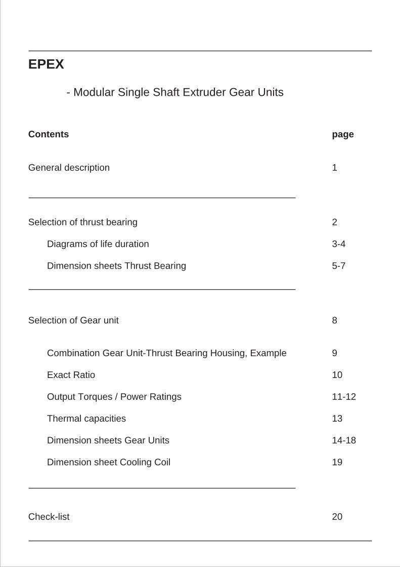
EPEX
- Modular Single Shaft Extruder Gear Units
Contents page
General description 1
Selection of thrust bearing 2
Diagrams of life duration 3-4
Dimension sheets Thrust Bearing 5-7
Selection of Gear unit 8
Combination Gear Unit-Thrust Bearing Housing, Example 9
Exact Ratio 10
Output Torques / Power Ratings 11-12
Thermal capacities 13
Dimension sheets Gear Units 14-18
Dimension sheet Cooling Coil 19
Check-list 20
ELECONModular Single Shaft Extruder Gear Units
General Points
Continuously working singe-screw extruder presses or single screw extruders, on account of their materials processing technology and construction demands on the driver assembly :
·To be capable of transmitting the high torques for pressurising and plasticising moulding materials and synthetics required for fibre line production and secondly
·Capability of absorbing the high thrust load induced by the process.
While the first point determines gearbox size and ratio, the axial forces and desired bearing life govern the axial bearing and its housing
In order to obtain an economical drive assembly which is adapted in the best possible way to the materials processing technical demands, Elecon has developed an
Extruder Gear Modular-Series
EPEX
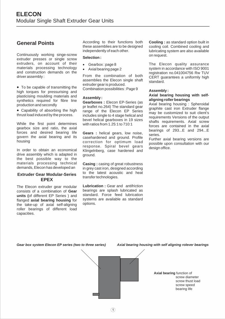
The Elecon extruder gear modular consists of a combination of Gear units (of different EP Series ) and flanged axial bearing housing for the take-up of axial self-aligning roller bearings of different load capacities.
According to their functions both these assemblies are to be designed independently of each other.
Selection :
·Gearbox : page 8·Axial bearing page 2
From the combination of both assemblies the Elecon single shaft extruder gear is produced.Combination possibilities : Page 9
Assembly :Gearboxes : Elecon EP-Series (as pr leaflet no.264) The standard gear range of the Elecon EP Series includes single to 4 stage helical and bevel helical gearboxes in 19 sizes with ratios from 1.25:1 to 710:1
Gears : helical gears, low noise, casehardened and ground. Profile correct ion for opt imum load response. Spiral bevel gears Klingelnberg, case hardened and ground.
Casing : casing of great robustness in grey cast iron, designed according to the latest acoustic and heat transfer technologies.
Lubrication : Gear and antifriction bearings are splash lubricated as standard. Force feed lubrication systems are available as standard options.
Cooling : as standard option built in cooling coil. Combined cooling and lubricating system are also available on request.
The Elecon quality assurance system in accordance with ISO 9001 registration no.041004756 Rw TUV CERT guarantees a uniformly high standard.
Assembly :Axial bearing housing with self-aligning roller bearingsAxial bearing housing : Spheroidal graphite cast iron Extruder flange may be customized to suit client’s requirements Versions of the output shafts requirements. Axial screw forces are contained in the axial bearings of 293...E and 294...E series.Further axial bearing versions are possible upon consultation with our design office.
Gear box system Elecon EP series (two to three series) Axial bearing housing with self aligning rolever bearings
Axial bearing function of screw diameter screw thust load screw speed bearing life
Fax = ppppp. .Pa
The necessary dynamical bearingcapacity of the thrust bearing
Crequ [kN]
Crequ = fd. Fax .
Crequ < Cselection table
Rating example
Screw diameter : Ds = 80 mmWorking pressure : Pa = 500 bar
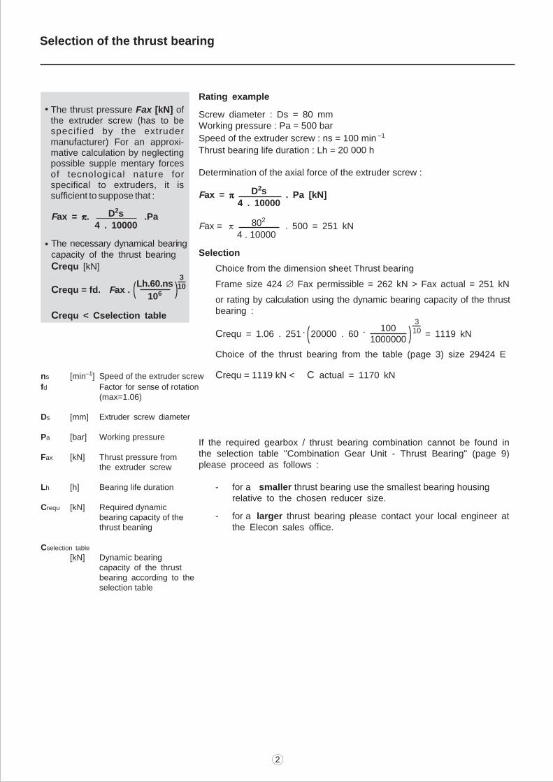
Speed of the extruder screw : ns = 100 min –1
Thrust bearing life duration : Lh = 20 000 h
Determination of the axial force of the extruder screw :
Fax = ppppp . Pa [kN]
Fax = p . 500 = 251 kN
Selection
Choice from the dimension sheet Thrust bearing
Frame size 424 Æ Fax permissible = 262 kN > Fax actual = 251 kN
or rating by calculation using the dynamic bearing capacity of the thrustbearing :
Crequ = 1.06 . 251 20000 . 60 = 1119 kN
Choice of the thrust bearing from the table (page 3) size 29424 E
Crequ = 1119 kN < C actual = 1170 kN
If the required gearbox / thrust bearing combination cannot be found inthe selection table "Combination Gear Unit - Thrust Bearing" (page 9)please proceed as follows :
- for a smaller thrust bearing use the smallest bearing housingrelative to the chosen reducer size.
- for a larger thrust bearing please contact your local engineer atthe Elecon sales office.
( )
( )3
10Lh.60.ns
106
D2s
4 . 10000
802
4 . 10000
310
ns [min–1] Speed of the extruder screw
fd Factor for sense of rotation(max=1.06)
Ds [mm] Extruder screw diameter
Pa [bar] Working pressure
Fax [kN] Thrust pressure fromthe extruder screw
Lh [h] Bearing life duration
Crequ [kN] Required dynamicbearing capacity of thethrust beaning
Cselection table
[kN] Dynamic bearingcapacity of the thrustbearing according to theselection table
. . 1001000000
D2s
4 . 10000
The thrust pressure Fax [kN] of the extruder screw (has to be specif ied by the extruder manufacturer) For an approxi-mative calculation by neglecting possible supple mentary forces of tecnological nature for specifical to extruders, it is sufficient to suppose that :
Selection of the thrust bearing
Requested thrust bearing life duration
20 000 hP
erm
issi
ble
axi
al
forc
eF
ax
allo
w.
[kN
]
Speed of the extruder screw
[min–1]
Perm
issi
ble
axi
al f
orc
eF
ax
allo
w.
[kN
]
Speed of the extruder screw
[min–1]
30 000 h
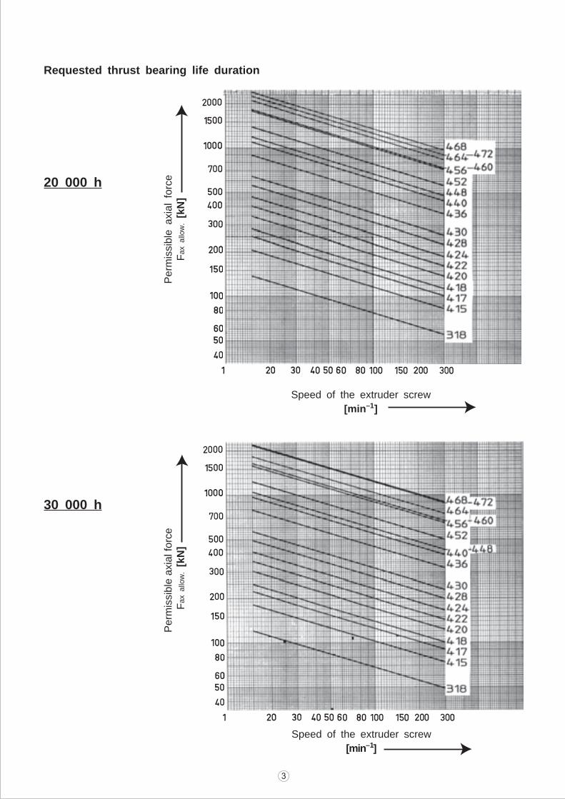
40 000 h
Pe
rmis
sib
le a
xia
l fo
rce
Fax
allo
w.
[kN
]
Speed of the extruder screw
[min–1]
Requested thrust bearing life duration
Perm
issi
ble
axi
al
forc
eF
ax
allo
w.
[kN
]
Speed of the extruder screw
[min–1]
50 000 h
EPEX
TypeDinamiccapacity
[kN]Index LT F dL dG t3 x
No
. O
f
Bo
lts
V LH Li
Keys
Axial self aligning roller bearing Thrust bearing housing Hollow shaft
X.14-318
X.14-415
X.14-417
X.14-418
X.14-420
345
518
633
702
863
29318E
29415E
29417E
29418E
29420E
250
250
280
280
298
160
160
180
190
210
95
108
120
125
140
8
8
8
8
8
210
210
230
240
260
M16
M16
M20
M20
M20
30
30
35
35
35
5
5
5
5
5
8
8
8
8
8
110
100
110
110
120
336
365
361
366
381
50
45
50
50
50
61
57
61
61
61
100
80
100
100
100
1
2
1
1
1
25
25
25
25
25
X.16-418
X.16-420
X.16-422
X.16-424
702
863
1010
1170
29418E
29420E
29422E
29424E
280
298
330
355
190
210
230
250
125
140
145
150
8
8
8
10
240
260
280
310
M20
M20
M24
M24
35
35
40
40
5
5
5
5
8
8
8
8
110
120
130
150
386
381
386
391
50
60
70
80
61
74
84
95
110
90
120
100
2
2
1
1
30
30
30
30
X.18-420
X.18-422
X.18-424
X.18-428
863
1010
1170
1400
29420E
29422E
29424E
29428E
298
330
355
378
210
230
250
280
140
145
150
170
8
8
10
10
260
280
310
340
M20
M24
M24
M24
35
40
40
40
5
5
5
5
8
8
8
8
120
130
150
170
469
454
459
479
60
70
80
80
74
84
96
96
130
110
140
140
2
2
1
1
30
30
30
30
X.20-424
X.20-428
X.20-430
1170
1400
1610
29424E
29428E
29430E
355
378
410
250
280
300
150
170
175
10
10
10
310
340
360
M24
M24
M24
40
40
40
5
5
5
8
8
8
150
170
180
484
479
484
80
90
100
96
106
118
110
150
120
2
1
1
40
40
40
X.22-428
X.22-430
X.22-436
1400
1610
2250
29428E
29430E
29436E
378
410
468
280
300
360
170
175
205
10
10
10
340
360
420
M24
M24
M30
40
40
50
5
5
5
8
8
8
170
180
220
543
548
578
90
100
130
106
118
151
140
160
140
2
1
1
40
40
40
X.25-436
X.25-440
2250
2760
29436E
29440E
468
510
360
400
205
225
10
12
420
460
M30
M30
50
50
5
5
8
8
220
240
606
626
130
140
151
165
170
150
1
1
50
50
X.28-436
X.28-440
X.28-448
2250
2760
2990
29436E
29440E
29448E
468
510
558
360
400
440
205
225
230
10
12
12
420
460
510
M30
M30
M36
50
50
60
5
5
5
8
8
8
220
240
290
670
690
695
130
140
170
151
165
197
150
180
180
2
1
1
60
60
60
X.31-440
X.31-448
X.31-452
2760
2990
3510
29440E
29448E
29452E
510
558
620
400
440
480
225
230
245
12
12
12
460
510
550
M30
M36
M36
50
60
60
5
5
5
8
8
8
240
290
310
692
697
712
140
170
180
165
197
210
160
180
200
2
1
1
60
60
60
X.35-440
X.35-448
X.35-452
X.35-456
2760
2990
3510
4310
29440E
29448E
29452E
29456E
510
570
620
680
400
440
480
520
335
340
360
395
23
23
23
27.5
460
510
550
600
M30
M36
M36
M36
50
60
60
60
10
10
10
10
8
12
12
12
200
240
260
280
840
845
865
900
130
170
190
200
147
191
213
223
195
255
285
300
2
1
1
1
60
60
60
70
X.40-448
X.40-452
X.40-456
X.40-460
2990
3510
4310
4370
29448E
29452E
29456E
29460E
570
620
680
700
440
480
520
540
325
355
385
410
23
23
27.5
32.5
510
550
600
620
M36
M36
M36
M36
60
60
60
60
10
10
10
10
12
12
12
12
240
260
280
300
835
865
895
920
170
190
200
220
191
213
223
245
255
285
300
330
2
2
1
1
60
60
70
70
X.42-452
X.42-456
X.42-460
X.42-464
3510
4310
4370
4950
29452E
29456E
29460E
29464E
620
680
700
800
480
520
540
650
355
385
410
445
23
27.5
32.5
33
550
600
620
720
M36
M36
M36
M36
60
60
60
60
10
10
10
10
12
12
12
12
260
280
300
320
930
960
985
1020
190
200
220
240
213
223
245
267
285
300
330
360
2
2
1
1
60
70
70
80
X.45-456
X.45-460
X.45-464
X.45-468
4310
4370
4950
5750
29456E
29460E
29464E
29468E
680
700
800
860
520
540
650
700
385
410
445
500
27.5
32.5
33
40
600
620
720
780
M36
M36
M36
M42
60
60
60
70
10
10
10
10
12
12
12
12
280
300
320
340
985
1010
1045
1100
200
220
240
250
223
245
267
277
300
330
360
375
2
2
1
1
70
70
80
80
X.47-460
X.47-464
X.47-468
X.47-472
4370
4950
5750
5350
29460E
29464E
29468E
29472E
700
800
860
900
540
650
700
700
370
405
470
490
32.5
33
40
41.5
620
720
780
800
M36
M36
M42
M42
60
60
70
70
10
10
10
10
12
12
12
12
300
320
340
360
975
1010
1075
1095
220
240
250
270
245
267
277
297
330
360
375
405
2
2
1
1
70
80
80
90
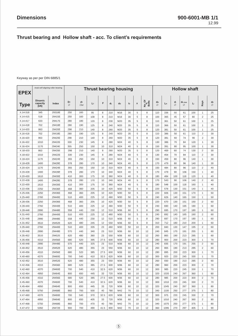
Thrust bearing and Hollow shaft - acc. To client’s requirements
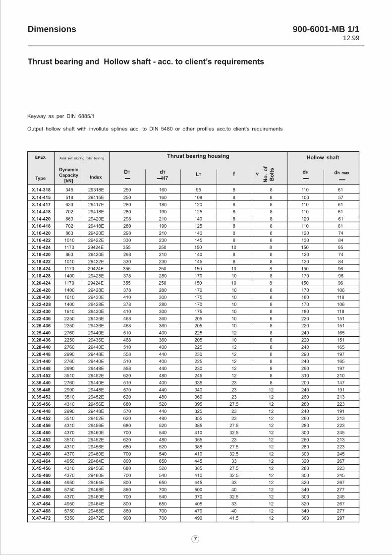
Keyway as per per DIN 6885/1
Dimensions 900-6001-MB 1/112.99
Dimensions 900-6001-MB 1/1
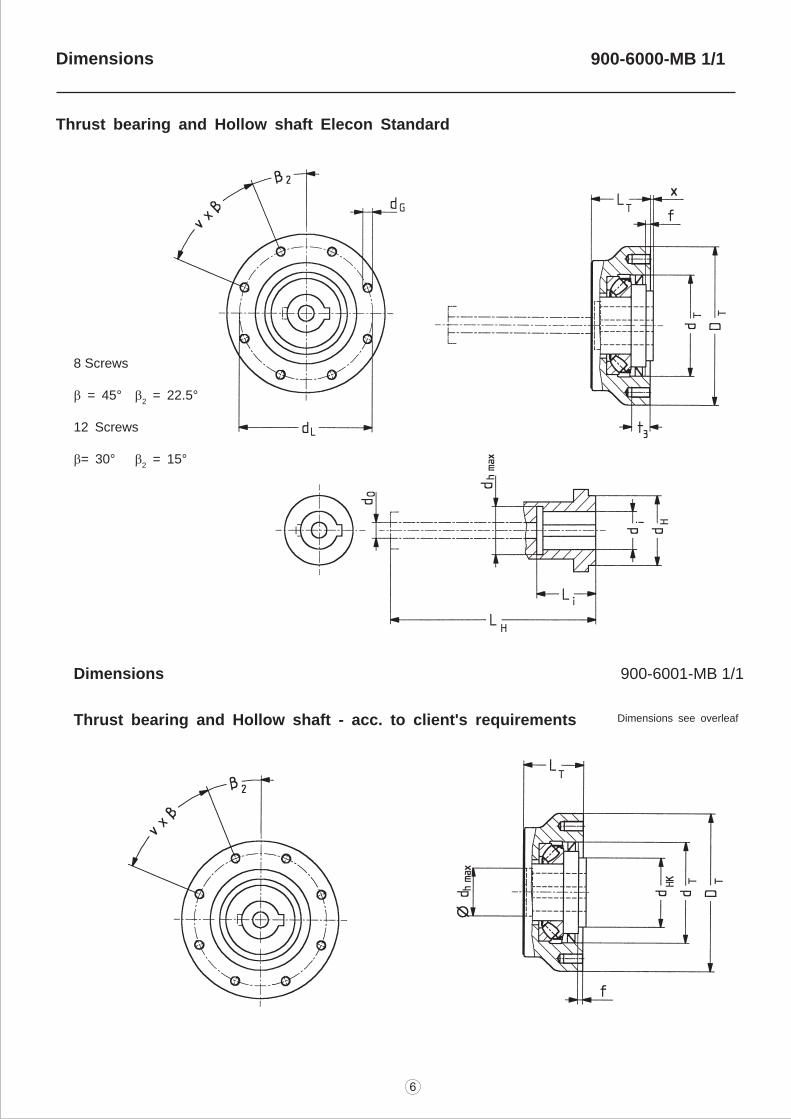
Thrust bearing and Hollow shaft - acc. to client's requirements Dimensions see overleaf
8 Screws
b = 45° b2 = 22.5°
12 Screws
b= 30° b2 = 15°
900-6000-MB 1/1
Thrust bearing and Hollow shaft Elecon Standard
Dimensions
Thrust bearing housing
Dimensions
Thrust bearing and Hollow shaft - acc. to client’s requirements
900-6001-MB 1/112.99
l Selection of type and size ofthe reducer
l Required ratio irequ =
l Choice of the correspondingnominal ratio iN
(for the actual ratio iN see the page 10)
l Selection of reducer sizeCheck of the nominal powerrating of the reducerPN Pe . f1f1 = application factor (between1.5 and 2.0 in accord.withELECON)
Determine the required torque
Trequ = 9550 .f1
l Selection of cooling systemPt Pe
Pt = Pt–
. f w . fA . f L
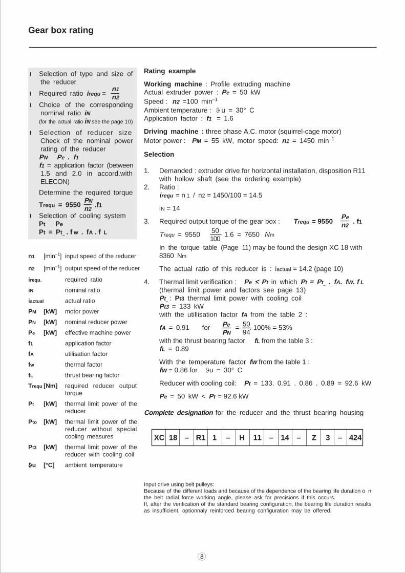
Rating example
Working machine : Profile extruding machineActual extruder power : Pe = 50 kW
Speed : n2 =100 min–1
Ambient temperature : u = 30° CApplication factor : f1 = 1.6
Driving machine : three phase A.C. motor (squirrel-cage motor)
Motor power : PM = 55 kW, motor speed: n1 = 1450 min–1
Selection
1. Demanded : extruder drive for horizontal installation, disposition R11with hollow shaft (see the ordering example)
2. Ratio :irequ = n 1 / n2 = 1450/100 = 14.5
iN = 14
3. Required output torque of the gear box : Trequ = 9550 . f1
Trequ = 9550 1.6 = 7650 Nm
In the torque table (Page 11) may be found the design XC 18 with8360 Nm
The actual ratio of this reducer is : iactual = 14.2 (page 10)
4. Thermal limit verification : Pe £ £ £ £ £ Pt in which Pt = Pt– . fA. fW. f L
(thermal limit power and factors see page 13)Pt
– : Pt3 thermal limit power with cooling coil
Pt3 = 133 kWwith the utillisation factor fA from the table 2 :
fA = 0.91 for = . 100% = 53%
with the thrust bearing factor fL from the table 3 :fL = 0.89
With the temperature factor fW from the table 1 :fW = 0.86 for Ju = 30° C
Reducer with cooling coil: Pt = 133. 0.91 . 0.86 . 0.89 = 92.6 kW
Pe = 50 kW < Pt = 92.6 kW
Complete designation for the reducer and the thrust bearing housing :
n1
n2
PN
n2
50100
Pe
n2
Pe
PN
5094
n1 [min–1] input speed of the reducer
n2 [min–1] output speed of the reducer
irequ. required ratio
iN nominal ratio
iactual actual ratio
PM [kW] motor power
PN [kW] nominal reducer power
Pe [kW] effective machine power
f1 application factor
fA utilisation factor
fw thermal factor
fL thrust bearing factor
Trequ [Nm] required reducer outputtorque
Pt [kW] thermal limit power of thereducer
Pto [kW] thermal limit power of thereducer without specialcooling measures
Pt3 [kW] thermal limit power of thereducer with cooling coil
JJJJJu [°C] ambient temperature
XC 18 – R1 1 – H 11 – 14 – Z 3 – 424
Input drive using belt pulleys:Because of the different loads and because of the dependence of the bearing life duration o nthe belt radial force working angle, please ask for precisions if this occurs.If, after the verification of the standard bearing configuration, the bearing life duration resultsas insufficient, optionnaly reinforced bearing configuration may be offered.
Gear box rating
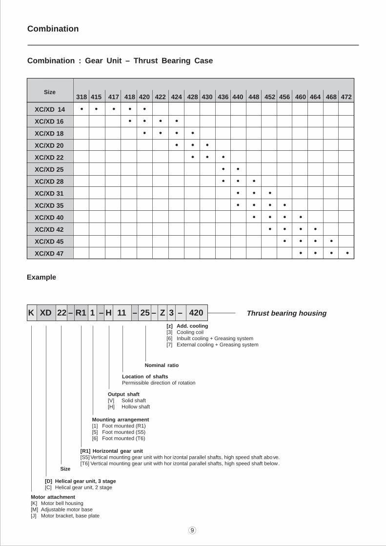
XC/XD 14
XC/XD 16
XC/XD 18
XC/XD 20
XC/XD 22
XC/XD 25
XC/XD 28
XC/XD 31
XC/XD 35
XC/XD 40
XC/XD 42
XC/XD 45
XC/XD 47
318 415 417 418 420 422 424 428 430 436 440 448 452 456 460 464 468 472
Location of shaftsPermissible direction of rotation
[z] Add. cooling[3] Cooling coil[6] Inbuilt cooling + Greasing system[7] External cooling + Greasing system
K XD 22 – R1 1 – H 11 – 25 – Z 3 – 420
Example
Nominal ratio
Output shaft[V] Solid shaft[H] Hollow shaft
Mounting arrangement[1] Foot mounted (R1)[5] Foot mounted (S5)[6] Foot mounted (T6)
[R1] Horizontal gear unit[S5] Vertical mounting gear unit with hor izontal parallel shafts, high speed shaft above.[T6] Vertical mounting gear unit with hor izontal parallel shafts, high speed shaft below.
Motor attachment[K] Motor bell housing[M] Adjustable motor base[J] Motor bracket, base plate
Size
[D] Helical gear unit, 3 stage[C] Helical gear unit, 2 stage
Size
Thrust bearing housing
Combination : Gear Unit – Thrust Bearing Case
Combination
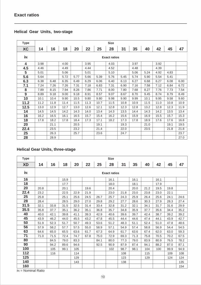
Type Size
XC
Exact ratiosiN
14 16 18 20 22 25 28 31 35 40 42 45 47
3.98 4.00 3.95 4.03 3.97 3.92
4.46 4.49 4.44 4.52 4.48 4.39
5.01 5.06 5.01 5.10 5.06 5.24 4.92 4.83
5.64 5.72 5.77 5.66 5.39 5.76 5.45 5.74 5.90 5.54 5.41
6.38 6.48 6.35 6.49 6.29 6.06 6.40 6.13 6.27 6.68 6.27 6.08 6.00
7.24 7.26 7.26 7.31 7.18 6.83 7.31 6.90 7.16 7.58 7.12 6.84 6.72
7.89 8.15 7.94 8.26 7.86 7.71 8.00 7.80 7.68 8.27 7.76 7.73 7.54
8.89 9.18 9.00 9.18 8.91 8.57 9.07 8.67 8.70 9.45 8.74 8.79 8.49
10.1 10.4 9.90 10.5 9.80 9.80 9.98 9.90 9.99 10.1 9.95 9.58 9.60
11.2 11.8 11.4 11.5 11.3 10.7 11.5 10.8 10.9 11.5 11.0 10.8 10.9
13.0 12.9 12.7 13.0 12.6 12.1 12.8 12.3 12.8 13.2 12.8 12.3 11.9
14.5 14.5 14.2 14.3 14.0 13.4 14.3 13.5 14.4 14.3 14.2 13.5 13.4
16.2 16.5 16.1 16.5 15.7 15.4 16.2 15.6 15.9 16.9 15.5 15.7 15.3
17.8 18.2 17.8 18.4 17.3 17.1 18.2 17.3 17.8 18.9 17.6 17.6 16.8
21.1 20.5 19.1 19.3 21.0 19.1 19.5
23.5 23.2 21.4 22.0 23.5 21.8 21.8
26.3 25.7 23.6 24.7 23.7
28.9 27.0
44.55
5.66.37.18910
11.212.514161820
22.42528
Type Size
XD
iN
14 16 18 20 22 25 28 31 35 40 42 45 47
161820
22.42528
31.535.54045505663718090100112125140160
Helical Gear Units, three-stage
Exact ratios
15.9 16.1 16.1 16.1
17.7 18.0 18.1 17.9
20.8 20.1 19.6 20.4 20.0 21.2 19.5 19.8
23.2 22.5 22.9 21.9 23.0 21.8 23.0 23.8 23.0 22.1
25.8 25.1 25.6 24.5 26.7 25.7 24.3 25.9 26.4 25.6 24.1 24.6
28.4 28.5 29.0 27.0 29.8 29.2 27.7 28.6 30.3 27.9 28.3 27.4
32.1 33.8 31.5 32.5 31.4 33.4 32.8 31.2 32.1 34.1 31.7 31.6 29.9
35.8 37.7 35.1 36.2 35.1 36.8 35.7 34.8 35.9 37.7 35.6 34.4 35.2
40.0 42.1 39.8 41.1 39.3 42.9 40.6 39.6 39.7 42.4 38.7 39.2 39.2
43.9 46.2 44.0 45.5 43.2 47.8 45.5 44.4 44.6 47.4 44.1 43.9 42.7
51.9 52.3 51.7 50.7 49.3 53.6 51.2 48.3 51.1 52.4 51.0 47.8 48.6
57.9 58.2 57.7 57.5 55.0 58.9 57.1 54.9 57.4 58.8 56.9 54.4 54.5
64.6 65.0 65.5 63.6 61.7 67.3 64.9 61.7 63.6 67.4 62.0 63.0 59.3
71.0 71.5 72.4 74.7 67.8 75.0 72.9 69.3 71.3 75.8 70.5 70.2 67.5
84.5 79.0 83.3 84.1 80.0 77.3 79.0 83.9 80.9 76.5 78.2
94.2 89.6 94.6 92.5 90.9 87.9 87.4 94.1 88.2 87.0 87.1
105 99.1 105 102 98.7 98.1 104 100 99.9 94.9
116 114 108 115 109 108
129 123 129 124 124
143 138 135
154
iN = Nominal Ratio
Exact ratios
Helical Gear Units, two-stage
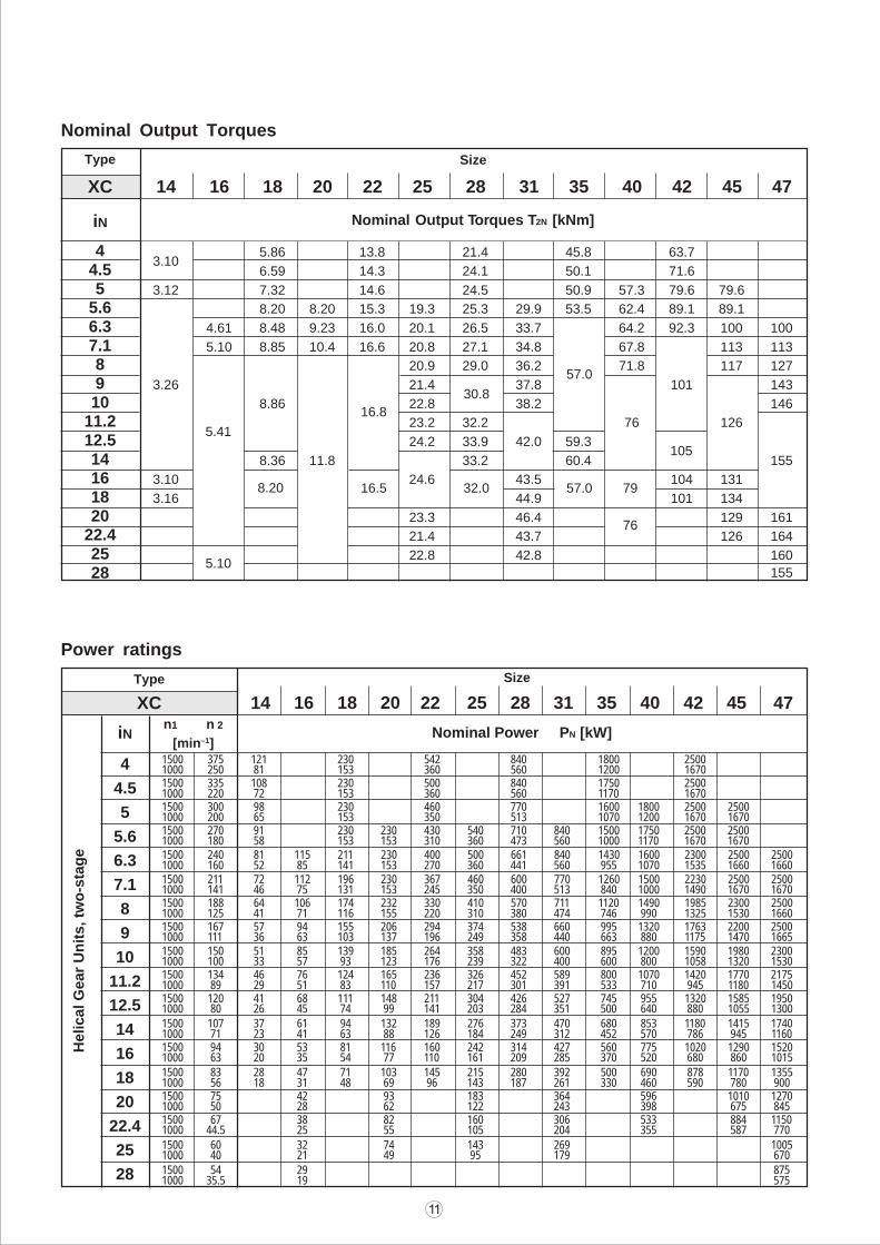
Power ratings
Type Size
14 16 18 20 22 25 28 31 35 40 42 45 47
4
4.5
5
5.6
6.3
7.1
8
9
10
11.2
12.5
14
16
18
20
22.4
25
28
iNn1 n 2
[min–1]Nominal Power PN [kW]
Helical G
ear
Un
its, tw
o-s
tag
e
1500 375 121 230 542 840 1800 25001000 250 81 153 360 560 1200 16701500 335 108 230 500 840 1750 25001000 220 72 153 360 560 1170 16701500 300 98 230 460 770 1600 1800 2500 25001000 200 65 153 350 513 1070 1200 1670 16701500 270 91 230 230 430 540 710 840 1500 1750 2500 25001000 180 58 153 153 310 360 473 560 1000 1170 1670 16701500 240 81 115 211 230 400 500 661 840 1430 1600 2300 2500 25001000 160 52 85 141 153 270 360 441 560 955 1070 1535 1660 16601500 211 72 112 196 230 367 460 600 770 1260 1500 2230 2500 25001000 141 46 75 131 153 245 350 400 513 840 1000 1490 1670 16701500 188 64 106 174 232 330 410 570 711 1120 1490 1985 2300 25001000 125 41 71 116 155 220 310 380 474 746 990 1325 1530 16601500 167 57 94 155 206 294 374 538 660 995 1320 1763 2200 25001000 111 36 63 103 137 196 249 358 440 663 880 1175 1470 16651500 150 51 85 139 185 264 358 483 600 895 1200 1590 1980 23001000 100 33 57 93 123 176 239 322 400 600 800 1058 1320 15301500 134 46 76 124 165 236 326 452 589 800 1070 1420 1770 21751000 89 29 51 83 110 157 217 301 391 533 710 945 1180 14501500 120 41 68 111 148 211 304 426 527 745 955 1320 1585 19501000 80 26 45 74 99 141 203 284 351 500 640 880 1055 13001500 107 37 61 94 132 189 276 373 470 680 853 1180 1415 17401000 71 23 41 63 88 126 184 249 312 452 570 786 945 11601500 94 30 53 81 116 160 242 314 427 560 775 1020 1290 15201000 63 20 35 54 77 110 161 209 285 370 520 680 860 10151500 83 28 47 71 103 145 215 280 392 500 690 878 1170 13551000 56 18 31 48 69 96 143 187 261 330 460 590 780 9001500 75 42 93 183 364 596 1010 12701000 50 28 62 122 243 398 675 8451500 67 38 82 160 306 533 884 11501000 44.5 25 55 105 204 355 587 770
1500 60 32 74 143 269 10051000 40 21 49 95 179 6701500 54 29 8751000 35.5 19 575
XC
Nominal Output Torques
Type Size
XC
iN
14 16 18 20 22 25 28 31 35 40 42 45 47
44.55
5.66.37.18910
11.212.514161820
22.42528
3.10
5.41
5.10
8.20 16.5
16.8
30.8
32.0
57.0
57.0 79
76
105
Nominal Output Torques T2N [kNm]
5.86 13.8 21.4 45.8 63.7
6.59 14.3 24.1 50.1 71.6
3.12 7.32 14.6 24.5 50.9 57.3 79.6 79.6
8.20 8.20 15.3 19.3 25.3 29.9 53.5 62.4 89.1 89.1
4.61 8.48 9.23 16.0 20.1 26.5 33.7 64.2 92.3 100 100
5.10 8.85 10.4 16.6 20.8 27.1 34.8 67.8 113 113
20.9 29.0 36.2 71.8 117 127
3.26 21.4 37.8 101 143
8.86 22.8 38.2 146
23.2 32.2 76 126
24.2 33.9 42.0 59.3
8.36 11.8 33.2 60.4 155
3.10 24.6 43.5 104 131
3.16 44.9 101 134
23.3 46.4 129 161
21.4 43.7 126 164
22.8 42.8 160
155
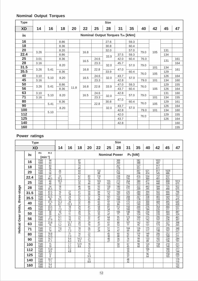
Power ratings
Type Size
14 16 18 20 22 25 28 31 35 40 42 45 47
16
18
20
22.4
25
28
31.5
35.5
40
45
50
56
63
71
80
90
100
112
125
140
160
iNn1 n 2
[min–1]Nominal Power PN [kW]
1500 94 87 300 582 10311000 63 58 200 388 6871500 83 73 267 527 9171000 56 49 178 351 6111500 75 26 64 132 252 447 621 817 10291000 50 17 43 88 168 298 414 545 6861500 67 23 62 83 118 238 294 416 554 737 9371000 44.5 15.2 41 55 79 159 195 277 369 491 6251500 60 19.5 53 74 103 155 213 264 380 477 660 808 10131000 40 13 35 49 69 103 142 176 253 318 440 539 6751500 54 18 46 66 93 130 180 256 322 443 584 735 9221000 35.5 12 29 39 62 87 120 171 209 295 389 490 6151500 47.5 16 27 41 59 84 113 160 235 284 394 502 666 7961000 31.5 11 18 27 39 56 75 107 157 189 263 333 444 5311500 42.5 14 24 37 52 74 101 150 208 267 338 465 569 7131000 28 9.3 16 25 35 49 67 100 139 178 223 310 379 4751500 37.5 12.2 20 32 46 65 97 126 172 224 300 409 495 6451000 25 8.1 13.3 21 31 43 65 84 115 149 200 273 330 4301500 33.5 11 18 29 41 58 81 112 150 200 276 354 466 5571000 22.2 7.3 12 19 27 39 54 75 100 133 184 235 311 3711500 30 10 17 28 37 53 71 106 148 186 234 330 404 4871000 20 6.7 11 19 25 35 47 71 99 124 156 220 269 3241500 27 9.1 15 23 32 47 64 95 123 169 215 295 356 4611000 17.9 6.1 10 15 21 31 43 63 82 113 142 197 236 3071500 23.8 7.7 12.7 20 29 41 61 80 107 142 197 259 327 3981000 16 5.2 8.5 13 19 27 41 53 71 95 131 173 218 2651500 21 7.0 11 18 26 37 51 71 104 126 175 222 295 3401000 14 4.7 7.3 12 17 24 34 47 69 84 117 148 197 2271500 18.8 11 16 23 45 60 92 119 149 206 252 3171000 12.5 7.3 11 15 30 40 61 79 99 137 168 2111500 16.7 9.4 14.3 21 40 56 76 99 133 182 220 2841000 11.1 6.3 9.5 13 27 37 51 66 89 121 146 1911500 15 7.7 12.9 18 50 67 90 124 158 210 2511000 10 5.1 8.6 12 33 45 60 83 105 140 1671500 13.4 7.2 17 59 106 180 2171000 8.9 4.8 11 39 71 120 1441500 12 15 55 96 158 2061000 8 9.9 37 64 105 1371500 10.7 13 48 1791000 7.1 8.8 32 1191500 9.4 1521000 6.3 102
XD
Helical G
ear
Un
its, th
ree-s
tag
eNominal Output Torques
Type Size
XD
iN
14 16 18 20 22 25 28 31 35 40 42 45 47
161820
22.42528
31.535.54045505663718090100112125140160
3.26
3.26
3.26
5.41
5.10
5.41
5.10
5.41
5.10
8.20
8.20
8.20
8.20
11.8
16.8
16.5
16.8
16.5
16.8
16.5
22.8
22.8
22.8
33.9
32.0
32.0
33.9
32.0
32.0
47.0
47.0
57.0
57.0
57.0
57.0
79.0
79.0
76.0
76.0
79.0
76.0
76.0
105
105
105
131
161
8.86 27.6 59.3
8.36 30.8 60.4
8.20 32.0 57.0 131
8.86 37.5 59.3 134
3.01 8.36 24.6 42.0 60.4 76.0 161
3.16 23.3 45.7 164
101 134
8.36 33.9 60.4 129
3.10 24.6 43.7 126 164
3.16 23.3 42.8 79.0 101 134 160
8.86 47.0 59.3 129 155
8.36 43.7 60.4 105 126 164
3.10 24.6 42.8 131 160
3.16 23.3 101 134 155
8.36 30.8 60.4 129 161
43.7 126 164
42.8 79.0 101 134 160
42.0 129 155
43.7 126 164
42.8 160
155
Nominal Output Torques T2N [kNm]
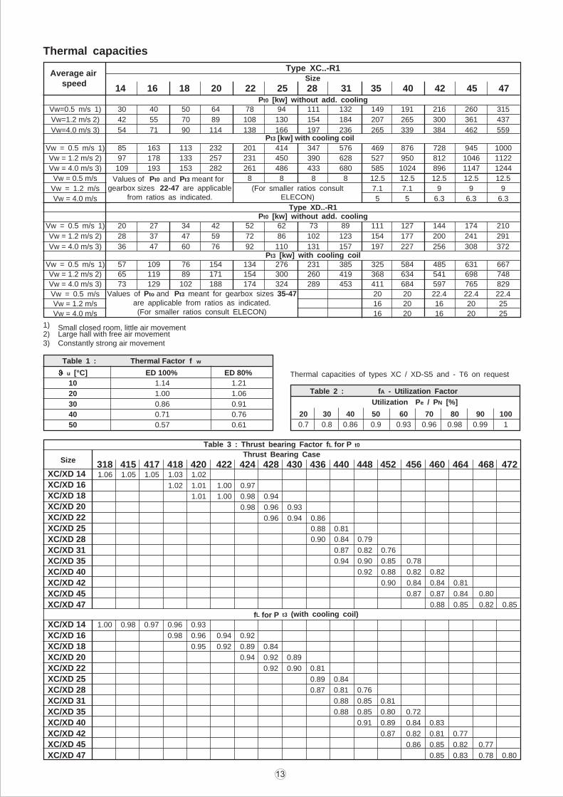
Thermal capacities
Size
Type XC..-R1Average air
speed14 16 18 20 22 25 28 31 35 40 42 45 47
Pt0 [kw] without add. coolingVw=0.5 m/s 1) 30 40 50 64 78 94 111 132 149 191 216 260 315
Vw=1.2 m/s 2) 42 55 70 89 108 130 154 184 207 265 300 361 437
Vw=4.0 m/s 3) 54 71 90 114 138 166 197 236 265 339 384 462 559Pt3 [kw] with cooling coil
Vw = 0.5 m/s 1) 85 163 113 232 201 414 347 576 469 876 728 945 1000
Vw = 1.2 m/s 2) 97 178 133 257 231 450 390 628 527 950 812 1046 1122
Vw = 4.0 m/s 3) 109 193 153 282 261 486 433 680 585 1024 896 1147 1244
Vw = 0.5 m/s 8 8 8 8 12.5 12.5 12.5 12.5 12.5
Vw = 1.2 m/s 7.1 7.1 9 9 9
Vw = 4.0 m/s 5 5 6.3 6.3 6.3
Values of Pt0 and Pt3 meant forgearbox sizes 22-47 are applicable
from ratios as indicated.(For smaller ratios consult
ELECON)
Vw = 0.5 m/s 1) 20 27 34 42 52 62 73 89 111 127 144 174 210
Vw = 1.2 m/s 2) 28 37 47 59 72 86 102 123 154 177 200 241 291
Vw = 4.0 m/s 3) 36 47 60 76 92 110 131 157 197 227 256 308 372
Vw = 0.5 m/s 1) 57 109 76 154 134 276 231 385 325 584 485 631 667
Vw = 1.2 m/s 2) 65 119 89 171 154 300 260 419 368 634 541 698 748
Vw = 4.0 m/s 3) 73 129 102 188 174 324 289 453 411 684 597 765 829
Vw = 0.5 m/s 20 20 22.4 22.4 22.4
Vw = 1.2 m/s 16 20 16 20 25
Vw = 4.0 m/s 16 20 16 20 25
Pt3 [kw] with cooling coil
Type XD..-R1Pt0 [kw] without add. cooling
Values of Pto and Pt3 meant for gearbox sizes 35-47are applicable from ratios as indicated.(For smaller ratios consult ELECON)
1) Small closed room, little air movement2) Large hall with free air movement3) Constantly strong air movement
Table 1 : Thermal Factor f w
JJJJJ u [°C] ED 100% ED 80%
10 1.14 1.21
20 1.00 1.06
30 0.86 0.91
40 0.71 0.76
50 0.57 0.61
Table 2 : fA - Utilization Factor
Utilization Pe / PN [%]
20 30 40 50 60 70 80 90 100
0.7 0.8 0.86 0.9 0.93 0.96 0.98 0.99 1
Thermal capacities of types XC / XD-S5 and - T6 on request
Table 3 : Thrust bearing Factor fL for P t0
Thrust Bearing CaseSize
318 415 417 418 420 422 424 428 430 436 440 448 452 456 460 464 468 472XC/XD 14
XC/XD 16
XC/XD 18
XC/XD 20
XC/XD 22
XC/XD 25
XC/XD 28
XC/XD 31
XC/XD 35
XC/XD 40
XC/XD 42
XC/XD 45
XC/XD 47
XC/XD 14
XC/XD 16
XC/XD 18
XC/XD 20
XC/XD 22
XC/XD 25
XC/XD 28
XC/XD 31
XC/XD 35
XC/XD 40
XC/XD 42
XC/XD 45
XC/XD 47
1.06 1.05 1.05 1.03 1.02
1.02 1.01 1.00 0.97
1.01 1.00 0.98 0.94
0.98 0.96 0.93
0.96 0.94 0.86
0.88 0.81
0.90 0.84 0.79
0.87 0.82 0.76
0.94 0.90 0.85 0.78
0.92 0.88 0.82 0.82
0.90 0.84 0.84 0.81
0.87 0.87 0.84 0.80
0.88 0.85 0.82 0.85
fL for P t3 (with cooling coil)
1.00 0.98 0.97 0.96 0.93
0.98 0.96 0.94 0.92
0.95 0.92 0.89 0.84
0.94 0.92 0.89
0.92 0.90 0.81
0.89 0.84
0.87 0.81 0.76
0.88 0.85 0.81
0.88 0.85 0.80 0.72
0.91 0.89 0.84 0.83
0.87 0.82 0.81 0.77
0.86 0.85 0.82 0.77
0.85 0.83 0.78 0.80
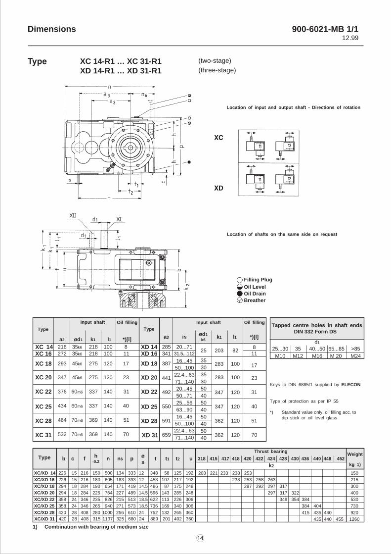
Dimensions
Type
Input shaft Oil filling
Type
a2 ød1 k1 l1 *)[l] a3 iN k1 l1ød1
k6*)[l]
Input shaft Oil filling
216 35k6 218 100 8
272 35k6 218 100 11
293 45k6 275 120 17
347 45k6 275 120 23
376 60m6 337 140 31
434 60m6 337 140 40
464 70m6 369 140 51
532 70m6 369 140 70
XC 14XC 16
XC 18
XC 20
XC 22
XC 25
XC 28
XC 31
XD 14XD 16
XD 18
XD 20
XD 22
XD 25
XD 28
XD 31
285
341
387
441
492
550
591
659
20...71
31.5...112
16...45
50...100
22.4...63
71...140
20...45
50...71
25...56
63...90
16...45
50...100
22.4...63
71...140
25
35
30
35
30
50
40
50
40
50
40
50
40
811
17
23
31
40
51
70
203 82
283 100
283 100
347 120
347 120
362 120
362 120
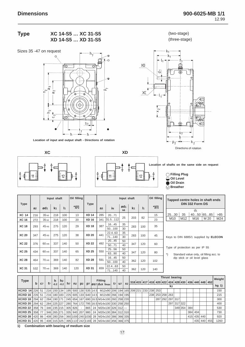
Tapped centre holes in shaft endsDIN 332 Form DS
d1
25...30 35 40...50 65...85 >85
M10 M12 M16 M 20 M24
Keys to DIN 6885/1 supplied by ELECON
Type of protection as per IP 55
*) Standard value only, oil filling acc. todip stick or oil level glass
Type b c f n n6 p t t1 t2 uh
-0.2 s
XC/XD 14 226 15 216 150 500 134 333 12 348 58 125 192
XC/XD 16 226 15 216 180 605 183 393 12 453 107 217 192
XC/XD 18 294 18 284 190 654 171 419 14.5 486 87 175 248
XC/XD 20 294 18 284 225 764 227 489 14.5 596 143 285 248
XC/XD 22 358 24 346 235 826 215 513 18.5 622 113 226 306
XC/XD 25 358 24 346 265 940 271 573 18.5 736 169 340 306
XC/XD 28 420 28 408 280 1000 256 610 24 752 132 265 360
XC/XD 31 420 28 408 315 1137 325 680 24 889 201 402 360
208 221 233 238 253 150
238 253 258 263 215
287 292 297 317 300
297 317 322 400
349 354 384 530
384 404 730
415 435 440 920
435 440 455 1260
318 415 417 418 420 422 424 428 430 436 440 448 452Weight
kg 1)
1) Combination with bearing of medium size
Location of input and output shaft - Directions of rotation
Location of shafts on the same side on request
Filling Plug
Oil Level
Oil Drain
Breather
Thrust bearing
k2
900-6021-MB 1/112.99
XC 14-R1 … XC 31-R1XD 14-R1 … XD 31-R1
(two-stage)
(three-stage)
Type
Location of input and output shaft - Directions of rotation
Location of shafts on the same side on request
Filling Plug
Oil Level
Oil Drain
Breather
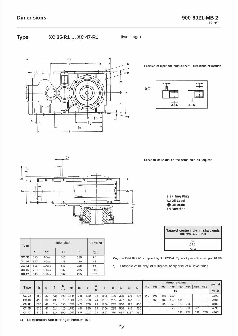
Type
a ød1 k1 l1 *)[l]
Oil filling
XC 35 570 90m6 446 180 60
XC 40 647 90m6 446 180 81
XC 42 693 100m6 537 215 98
XC 45 759 100m6 537 215 140
XC 47 845 100m6 537 215 187
Tapped centre hole in shaft ends DIN 332 Form DS
d1
M24
Keys to DIN 6885/1 supplied by ELECON. Type of protection as per IP 55
*) Standard value only, oil filling acc. to dip stick or oil level glass
k2
Thrust bearingWeight
kg 1)
440 448 452 456 460 464 468 472b c f nc n6 p t t1 t2 t3 uh
-0.2 sType
560 565 585 620 2150
550 580 610 635 2605
620 650 675 710 3185
650 675 710 765 4095
635 670 735 755 4860
XC 35 450 32 438 300 1346 345 610 24 1005 190 325 695 396
XC 40 450 32 438 375 1501 423 760 24 1157 265 477 847 396
XC 42 530 40 514 355 1652 422 720 28 1230 225 390 820 460
XC 45 530 40 514 425 1786 490 860 28 1356 285 516 946 460
XC 47 530 40 514 500 1957 575 1010 28 1527 370 687 1117 460
1) Combination with bearing of medium size
Input shaft90> _
Dimensions 900-6021-MB 212.99
XC 35-R1 … XC 47-R1 (two-stage)Type
Type
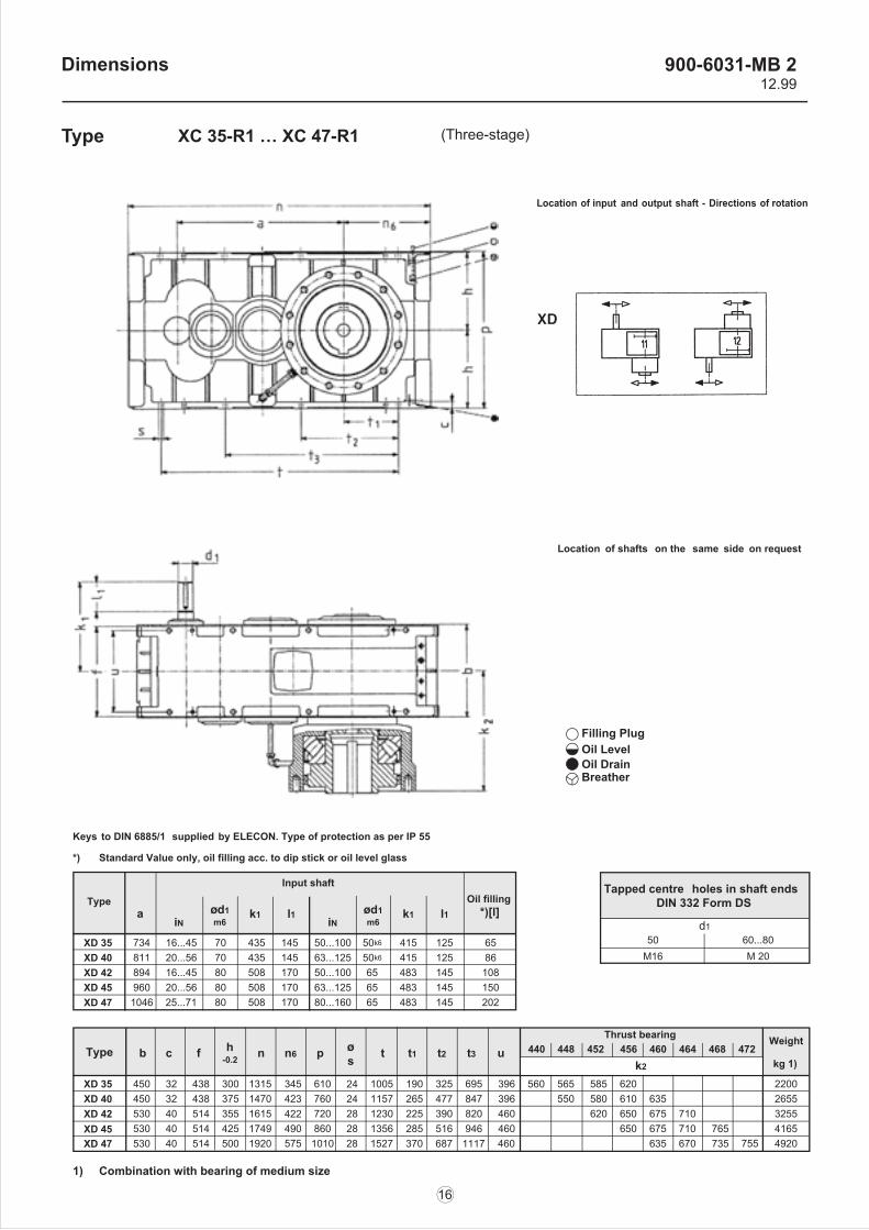
XD 35 734 16...45 70 435 145XD 40 811 20...56 70 435 145XD 42 894 16...45 80 508 170XD 45 960 20...56 80 508 170XD 47 1046 25...71 80 508 170
k2
Thrust bearing Weight
kg 1)440 448 452 456 460 464 468 472b c f n n6 p t t1 t2 t3 uh
-0.2 sType
560 565 585 620 2200550 580 610 635 2655
620 650 675 710 3255650 675 710 765 4165
635 670 735 755 4920
XD 35 450 32 438 300 1315 345 610 24 1005 190 325 695 396XD 40 450 32 438 375 1470 423 760 24 1157 265 477 847 396XD 42 530 40 514 355 1615 422 720 28 1230 225 390 820 460XD 45 530 40 514 425 1749 490 860 28 1356 285 516 946 460XD 47 530 40 514 500 1920 575 1010 28 1527 370 687 1117 460
1) Combination with bearing of medium size
Tapped centre holes in shaft ends DIN 332 Form DS
d150 60...80
M16 M 20
aiN
1m6
k1 l1iN
ød1m6
k1 l1Oil filling
*)[l]
50...100 50k6 415 125 6563...125 50k6 415 125 8650...100 65 483 145 10863...125 65 483 145 15080...160 65 483 145 202
*) Standard Value only, oil filling acc. to dip stick or oil level glass
Keys to DIN 6885/1 supplied by ELECON. Type of protection as per IP 55
Filling Plug Oil Level Oil Drain Breather
Location of input and output shaft - Directions of rotation
Location of shafts on the same side on request
Input shaft
Dimensions 900-6031-MB 212.99
XC 35-R1 … XC 47-R1 (Three-stage)Type
Sizes 35 -47 on request
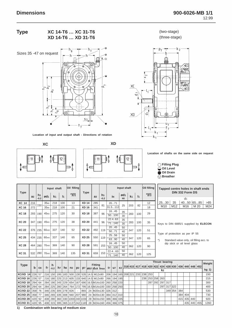
Location of input and output shaft - Directions of rotation
XC XD
Type
a2 ød1 k1 l1 *)[l]Type
a3 k1 l1 *)[l]iNød1
k6
XC 14 216 35 k6 218 100 13
XC 16 272 35 k6 218 100 20
XC 18 293 45 K6 275 120 29
XC 20 347 45 K6 275 120 38
XC 22 376 60 m6 337 140 50
XC 25 434 60 m6 337 140 65
XC 28 464 70 m6 369 140 82
XC 31 532 70 m6 369 140 120
XD 14 285
XD 16 341
XD 18 387
XD 20 441
XD 22 492
XD 25 550
XD 28 591
XD 31 659
20...71
31.5...112
16...45
50...100
22.4..63
71...140
20...45
50...71
25...56
63...90
16...45
50...100
22.4...63
71...140
203 82
283 100
283 100
347 120
347 120
362 120
362 120
15
23
35
45
60
80
102
140
25
35
30
35
30
50
40
50
40
50
40
50
40
d1
25...30 35 40...50 65...85 >85M10 M12 M16 M 20 M24
Keys to DIN 6885/1 supplied by ELECON
Type of protection as per IP 55
*) Standard value only, oil filling acc. todip stick or oil level glass
Filling Plug
Oil Level
Oil Drain
Breather
Typeb c7 f7 h7 n2 p2 p7
h-0.2
h2
-0.2
Fitting
øs7 dsx Imax t7 u7 x2
Thrust bearing
318 415 417 418 420 422 424 428 430 436 440 448 452
k2
226 51 216 150 134 195 500 130 535 14.5 M12x90 206 194 165
226 51 216 180 183 225 605 133 640 14.5 M12x90 266 194 195
294 62 284 190 171 245 654 167 690 16.5 M14x100 260 258 220
294 62 284 225 227 280 764 172 795 16.5 M14x100 330 258 250
358 76 346 235 215 305 826 - 865 24 M20x130 326 312 ––
358 77 346 265 271 335 940 207 980 24 M20x130 384 312 310
420 86 408 280 256 360 1000 240 1030 28 M24x150 386 366 335
420 95 408 315 325 395 1137 242 1165 28 M24x160 456 366 375
XC/XD 14
XC/XD 16
XC/XD 18
XC/XD 20
XC/XD 22
XC/XD 25
XC/XD 28
XC/XD 31
208 221 233 238 253 150
238 253 258 263 215
287 292 297 317 300
297 317 322 400
349 354 384 530
384 404 730
415 435 440 920
435 440 455 1260
Weight
kg 1)
1) Combination with bearing of medium size
Input shaft Oil filling Input shaft Oil filling
Location of shafts on the same side on request
Tapped centre holes in shaft endsDIN 332 Form DS
Dimensions 900-6025-MB 1/112.99
XC 14-S5 … XC 31-S5XD 14-S5 … XD 31-S5
(two-stage)
(three-stage)
Type
Sizes 35 -47 on request
Location of input and output shaft - Directions of rotation
XC XD
XC 14 216
XC 16 272
XC 18 293
XC 20 347
XC 22 376
XC 25 434
XC 28 464
XC 31 532
XD 14 285
XD 16 341
XD 18 387
XD 20 441
XD 22 492
XD 25 550
XD 28 591
XD 31 659
20...71
31.5...112
16...45
50...100
22.4..63
71...140
20...45
50...71
25...56
63...90
16...45
50...100
22.4...63
71...140
203 82
283 100
283 100
347 120
347 120
362 120
362 120
12
18
29
35
51
65
90
125
25
35
30
35
30
50
40
50
40
50
40
50
40
Keys to DIN 6885/1 supplied by ELECON
Type of protection as per IP 55
*) Standard value only, oil filling acc. todip stick or oil level glass
Filling Plug
Oil Level
Oil Drain
Breather
Location of shafts on the same side on request
Typeb c8 f7 h7 h8 n2 p2 p7
h-0.2
Fitting
øs7 dsx Imax t7 u7 x2
Thrust bearing
318 415 417 418 420 422 424 428 430 436 440 448 452
k2
226 57 216 150 195 183 500 130 535 14.5 M12x90 206 194 165
226 57 216 180 225 213 605 133 640 14.5 M12x90 266 194 195
294 64 284 190 245 229 654 167 690 16.5 M14x100 260 258 220
294 64 284 225 280 264 764 172 795 16.5 M14x100 330 258 250
358 76 346 235 305 278 826 - 865 24 M20x130 326 312 -
358 77 346 265 335 308 940 207 980 24 M20x130 384 312 310
420 92 408 280 360 330 1000 240 1030 28 M24x150 386 366 335
420 95 408 315 395 365 1137 242 1165 28 M24x160 456 366 375
XC/XD 14
XC/XD 16
XC/XD 18
XC/XD 20
XC/XD 22
XC/XD 25
XC/XD 28
XC/XD 31
208 221 233 238 253 150
238 253 258 263 215
287 292 297 317 300
297 317 322 400
349 354 384 530
384 404 730
415 435 440 920
435 440 455 1260
Weight
kg 1)
1) Combination with bearing of medium size
35k6 218 100 13
35k6 218 100 21
45K6 275 120 30
45K6 275 120 38
60m6 337 140 52
60m6 337 140 65
70m6 369 140 90
70m6 369 140 135
150
190
190
235
235
280
280
81
96
96
119
119
153
153
Tapped centre holes in shaft endsDIN 332 Form DS
d1
25...30 35 40...50 65...85 >85M10 M12 M16 M 20 M24
Type
a2 ød1 k1 l1
Oil filling
*)[l]Type
a3 k1 l1
Oil filling
*)[l]iN
ød1
k6
h1
-0.2
Input shaft Input shaft
h1
-0.2
Dimensions 900-6026-MB 1/112.99
XC 14-T6 … XC 31-T6XD 14-T6 … XD 31-T6
(two-stage)
(three-stage)
Type
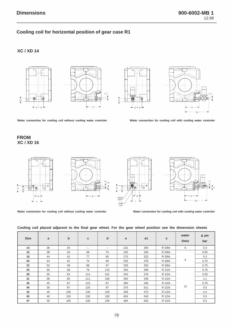
Cooling coil for horizontal position of gear case R1
XC / XD 14
Water connection for cooling coil without cooling water controler Water connection for cooling coil with cooling water controler
Water connection for cooling coil without cooling water controler Water connection for cooling coil with cooling water controler
Cooling coil placed adjacent to the final gear wheel. For the gear wheel position see the dimension sheets
Size a b c d e e1 swater
I/min
D D D D D pw
bar
14 36 34 – – 131 294 R 3/8A
16 38 34 38 74 192 346 R 3/8A
18 44 42 77 65 170 323 R 3/8A
20 44 42 74 69 225 378 R 3/8A
22 53 48 88 67 200 353 R 3/8A
25 55 48 76 115 263 399 R 1/2A
28 55 63 114 101 240 376 R 1/2A
31 58 60 111 106 300 436 R 1/2A
35 45 87 115 87 300 436 R 1/2A
40 35 97 125 97 375 511 R 1/2A
42 40 100 130 100 336 472 R 1/2A
45 40 100 130 100 404 540 R 1/2A
47 40 105 130 105 484 620 R 1/2A
0.3
0.55
0.3
0.75
0.75
0.75
0.55
1.1
0.75
0.5
0.4
0.5
0.5
6
6
12
XC / XD 16FROM
Dimensions 900-6002-MB 112.99
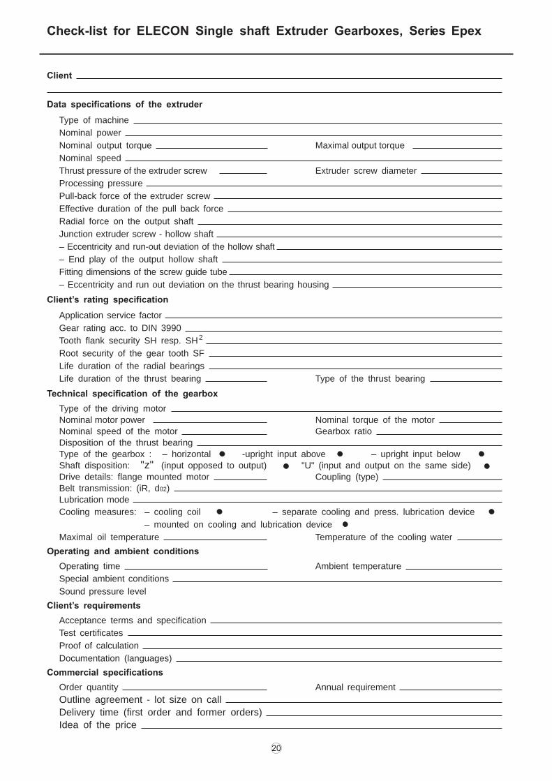
Check-list for ELECON Single shaft Extruder Gearboxes, Series Epex
Client
Data specifications of the extruder
Type of machine
Nominal power
Nominal output torque Maximal output torque
Nominal speed
Thrust pressure of the extruder screw Extruder screw diameter
Processing pressure
Pull-back force of the extruder screw
Effective duration of the pull back force
Radial force on the output shaft
Junction extruder screw - hollow shaft
– Eccentricity and run-out deviation of the hollow shaft
– End play of the output hollow shaft
Fitting dimensions of the screw guide tube
– Eccentricity and run out deviation on the thrust bearing housing
Client’s rating specification
Application service factor
Gear rating acc. to DIN 3990
Tooth flank security SH resp. SH2
Root security of the gear tooth SF
Life duration of the radial bearings
Life duration of the thrust bearing Type of the thrust bearing
Technical specification of the gearbox
Type of the driving motor
Nominal motor power Nominal torque of the motor
Nominal speed of the motor Gearbox ratio Disposition of the thrust bearing
Type of the gearbox : – horizontal -upright input above – upright input below
Shaft disposition: "z" (input opposed to output) "U" (input and output on the same side)
Drive details: flange mounted motor Coupling (type)
Belt transmission: (iR, d02)
Lubrication mode
Cooling measures: – cooling coil – separate cooling and press. lubrication device
– mounted on cooling and lubrication device
Maximal oil temperature Temperature of the cooling water
Operating and ambient conditions
Operating time Ambient temperature
Special ambient conditions
Sound pressure level
Client’s requirements
Acceptance terms and specification
Test certificates
Proof of calculation
Documentation (languages)
Commercial specifications
Order quantity Annual requirement
Outline agreement - lot size on call
Delivery time (first order and former orders)
Idea of the price