Embed Size (px)
Citation preview
SIZE: 10”to17”
ELECONSUPER SERIES
ww
w.
el
ec
on
.c
om
Cata
logue N
o.: 2
03/G
/02/2
011
IN WORM GEAR UNITS
k3
k2
d1
D1
k1
k
FILLER PLUGk5 k4
V2
ae
d2
D2
p
c
snbf
h2
h1
L1
V1
t2t1
u1
u1
OUTPUT SHAFT
KEYWAY DETAILINPUT SHAFT
KEYWAY DETAIL
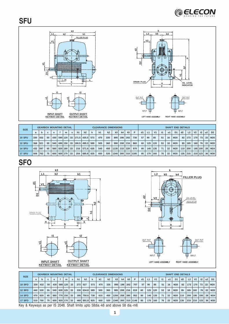
SIZEGEARBOX MOUNTING DETAIL CLEARANCE DIMENSIONS SHAFT END DETAILS
a b c e f m s h1 h2 k k1 k2 k3 k4 k5 P d1 L1 V1 t1 u1 D1 d2 L2 V2 t2 u2 D2
10 SFO 330 432 50 430 580 120 33 273 527 573 470 335 895 198 202 707 57 90 85 51 16 M20 82 173 170 73 22 M20
SFO
Key & Keyways as per IS 2048. Shaft limits upto 58dia.-k6 and above 58 dia.-m6
12 SFO 440 530 55 540 630 125 33 330 634.8 589 500 360 985 208 216 819 60 125 120 53 18 M20 85 165 160 76 22 M20
14 SFO 470 620 65 560 770 150 33 395 750.6 738 610 450 1200 258 280 952 80 140 135 71 22 M20 110 200 195 100 28 M24
17 SFO 510 750 75 600 920 170 33 460 891.8 825 650 520 1340 300 310 1146 85 170 160 76 22 M20 135 215 210 123 36 M30
k3
k2L1
V1d
1
D1
C
b
m
f
s
t2t1
u1
u1
k1
OUTPUT SHAFTKEYWAY DETAIL
INPUT SHAFTKEYWAY DETAIL
FILLER PLUG
SFU
SIZEGEARBOX MOUNTING DETAIL CLEARANCE DIMENSIONS SHAFT END DETAILS
a b c e f m s h1 h2 k k1 k2 k3 k4 k5 P d1 L1 V1 t1 u1 D1 d2 L2 V2 t2 u2 D2
10 SFU 330 432 50 430 590 120 33 171.5 425.5 573 470 335 895 198 202 730 57 90 85 51 16 M20 82 173 170 73 22 M20
17 SFU 508 762 75 600 920 170 33 254 685.8 825 650 520 1340 300 310 1185 85 170 160 78 22 M20 135 215 210 123 36 M30
k
k5
ae
k4L2
V2
d2
D2
P
h2
h1
12 SFU 368 521 55 540 690 150 33 190.5 495.3 589 505 360 990 208 216 860 60 125 120 53 18 M20 85 165 160 76 22 M20
14 SFU 432 597 65 560 820 180 33 216 571.6 635 545 450 1135 215 220 970 80 140 135 71 22 M20 110 200 195 100 28 M24
1
b
L2
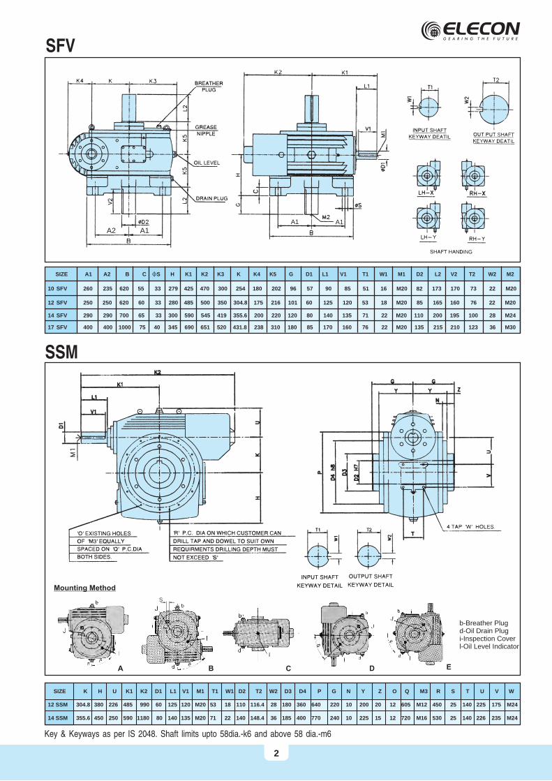
SFV
SSM
12 SFV 250 620 60 33 280 485 500 350 304.8 175 216 101 60 125 120 53 18 M20 85 165 160 76 22 M20
10 SFV 260
14 SFV 290 700 65 33 300 590 545 419 355.6 200 220 120 80 140 135 71 22 M20 110 200 195 100 28 M24
17 SFV 400 1000 75 40 345 690 651 520 431.8 238 310 180 85 170 160 76 22 M20 135 215 210 123 36 M30
SIZE K H U K1 K2 D1 L1 V1 M1 T1 W1 D2 T2 W2 D3 D4 P G N Y Z O Q M3 R S T U V W
12 SSM 304.8 380 226 485 990 60 125 120 M20 53 18 110 116.4 28 180 360 640 220 10 200 20 12 605 M12 450 25 140 225 175 M24
14 SSM 355.6 450 250 590 1180 80 140 135 M20 71 22 140 148.4 36 185 400 770 240 10 225 15 12 720 M16 530 25 140 226 235 M24
Key & Keyways as per IS 2048. Shaft limits upto 58dia.-k6 and above 58 dia.-m6
SIZE A1 A2 B C FS H K1 K2 K3 K K4 K5 G D1 L1 V1 T1 W1 M1 D2 L2 V2 T2 W2 M2
A2 A1A1 A1
235 620 55 33 279 425 470 300 254 180 202 96 57 90 85 51 16 M20 82 173 170 73 22 M20
250
290
400
2
b-Breather Plugd-Oil Drain Plugi-Inspection Coverl-Oil Level Indicator
A B C D E
Mounting Method
S
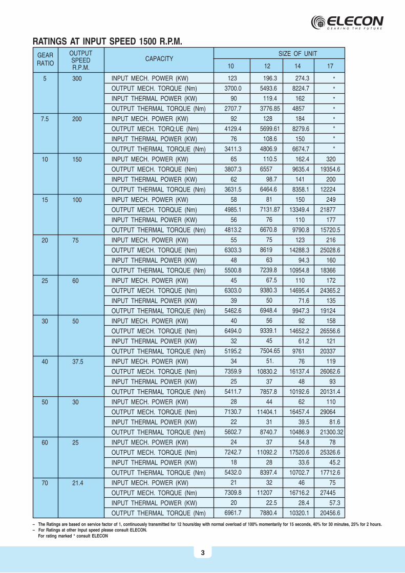
RATINGS AT INPUT SPEED 1500 R.P.M.
– The Ratings are based on service factor of 1, continuously transmitted for 12 hours/day with normal overload of 100% momentarily for 15 seconds, 40% for 30 minutes, 25% for 2 hours.– For Ratings at other Input speed please consult ELECON.
For rating marked * consult ELECON
GEARRATIO
OUTPUTSPEEDR.P.M.
CAPACITY
INPUT MECH. POWER (KW)
OUTPUT MECH. TORQUE (Nm)
INPUT THERMAL POWER (KW)
OUTPUT THERMAL TORQUE (Nm)
INPUT MECH. POWER (KW)
OUTPUT MECH. TORQ;UE (Nm)
INPUT THERMAL POWER (KW)
OUTPUT THERMAL TORQUE (Nm)
INPUT MECH. POWER (KW)
OUTPUT MECH. TORQUE (Nm)
INPUT THERMAL POWER (KW)
OUTPUT THERMAL TORQUE (Nm)
INPUT MECH. POWER (KW)
OUTPUT MECH. TORQUE (Nm)
INPUT THERMAL POWER (KW)
OUTPUT THERMAL TORQUE (Nm)
INPUT MECH. POWER (KW)
OUTPUT MECH. TORQUE (Nm)
INPUT THERMAL POWER (KW)
OUTPUT THERMAL TORQUE (Nm)
INPUT MECH. POWER (KW)
OUTPUT MECH. TORQUE (Nm)
INPUT THERMAL POWER (KW)
OUTPUT THERMAL TORQUE (Nm)
INPUT MECH. POWER (KW)
OUTPUT MECH. TORQUE (Nm)
INPUT THERMAL POWER (KW)
OUTPUT THERMAL TORQUE (Nm)
INPUT MECH. POWER (KW)
OUTPUT MECH. TORQUE (Nm)
INPUT THERMAL POWER (KW)
OUTPUT THERMAL TORQUE (Nm)
INPUT MECH. POWER (KW)
OUTPUT MECH. TORQUE (Nm)
INPUT THERMAL POWER (KW)
OUTPUT THERMAL TORQUE (Nm)
INPUT MECH. POWER (KW)
OUTPUT MECH. TORQUE (Nm)
INPUT THERMAL POWER (KW)
OUTPUT THERMAL TORQUE (Nm)
INPUT MECH. POWER (KW)
OUTPUT MECH. TORQUE (Nm)
INPUT THERMAL POWER (KW)
OUTPUT THERMAL TORQUE (Nm)
5 300
7.5 200
10 150
15 100
20 75
25 60
30 50
40 37.5
50 30
60 25
70 21.4
SIZE OF UNIT
123
3700.0
90
2707.7
92
4129.4
76
3411.3
65
3807.3
62
3631.5
58
4985.1
56
4813.2
55
6303.3
48
5500.8
45
6303.0
39
5462.6
40
6494.0
32
5195.2
34
7359.9
25
5411.7
28
7130.7
22
5602.7
24
7242.7
18
5432.0
21
7309.8
20
6961.7
10
196.3
5493.6
119.4
3776.85
128
5699.61
108.6
4806.9
110.5
6557
98.7
6464.6
81
7131.87
76
6670.8
75
8619
63
7239.8
67.5
9380.3
50
6948.4
56
9339.1
45
7504.65
51.
10830.2
37
7857.8
44
11404.1
31
8740.7
37
11092.2
28
8397.4
32
11207
22.5
7880.4
12
274.3
8224.7
162
4857
184
8279.6
150
6674.7
162.4
9635.4
141
8358.1
150
13349.4
110
9790.8
123
14288.3
94.3
10954.8
110
14695.4
71.6
9947.3
92
14652.2
61.2
9761
76
16137.4
48
10192.6
62
16457.4
39.5
10486.9
54.8
17520.6
33.6
10702.7
46
16716.2
28.4
10320.1
14 17
*
*
*
*
*
*
*
*
320
19354.6
200
12224
249
21877
177
15720.5
216
25028.6
160
18366
172
24365.2
135
19124
158
26556.6
121
20337
119
26062.6
93
20131.4
110
29064
81.6
21300.32
78
25326.6
45.2
17712.6
75
27445
57.3
20456.6
3
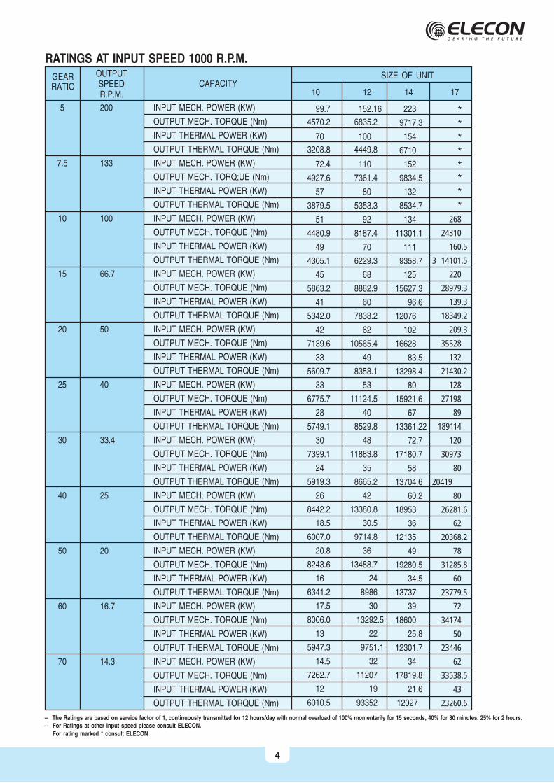
RATINGS AT INPUT SPEED 1000 R.P.M.
GEARRATIO
OUTPUTSPEEDR.P.M.
CAPACITYSIZE OF UNIT
5 200
7.5 133
10 100
15 66.7
20 50
25 40
30 33.4
40 25
50 20
60 16.7
70 14.3
INPUT MECH. POWER (KW)
OUTPUT MECH. TORQUE (Nm)
INPUT THERMAL POWER (KW)
OUTPUT THERMAL TORQUE (Nm)
INPUT MECH. POWER (KW)
OUTPUT MECH. TORQ;UE (Nm)
INPUT THERMAL POWER (KW)
OUTPUT THERMAL TORQUE (Nm)
INPUT MECH. POWER (KW)
OUTPUT MECH. TORQUE (Nm)
INPUT THERMAL POWER (KW)
OUTPUT THERMAL TORQUE (Nm)
INPUT MECH. POWER (KW)
OUTPUT MECH. TORQUE (Nm)
INPUT THERMAL POWER (KW)
OUTPUT THERMAL TORQUE (Nm)
INPUT MECH. POWER (KW)
OUTPUT MECH. TORQUE (Nm)
INPUT THERMAL POWER (KW)
OUTPUT THERMAL TORQUE (Nm)
INPUT MECH. POWER (KW)
OUTPUT MECH. TORQUE (Nm)
INPUT THERMAL POWER (KW)
OUTPUT THERMAL TORQUE (Nm)
INPUT MECH. POWER (KW)
OUTPUT MECH. TORQUE (Nm)
INPUT THERMAL POWER (KW)
OUTPUT THERMAL TORQUE (Nm)
INPUT MECH. POWER (KW)
OUTPUT MECH. TORQUE (Nm)
INPUT THERMAL POWER (KW)
OUTPUT THERMAL TORQUE (Nm)
INPUT MECH. POWER (KW)
OUTPUT MECH. TORQUE (Nm)
INPUT THERMAL POWER (KW)
OUTPUT THERMAL TORQUE (Nm)
INPUT MECH. POWER (KW)
OUTPUT MECH. TORQUE (Nm)
INPUT THERMAL POWER (KW)
OUTPUT THERMAL TORQUE (Nm)
INPUT MECH. POWER (KW)
OUTPUT MECH. TORQUE (Nm)
INPUT THERMAL POWER (KW)
OUTPUT THERMAL TORQUE (Nm)
99.7
4570.2
70
3208.8
72.4
4927.6
57
3879.5
51
4480.9
49
4305.1
45
5863.2
41
5342.0
42
7139.6
33
5609.7
33
6775.7
28
5749.1
30
7399.1
24
5919.3
26
8442.2
18.5
6007.0
20.8
8243.6
16
6341.2
17.5
8006.0
13
5947.3
14.5
7262.7
12
6010.5
10
152.16
6835.2
100
4449.8
110
7361.4
80
5353.3
92
8187.4
70
6229.3
68
8882.9
60
7838.2
62
10565.4
49
8358.1
53
11124.5
40
8529.8
48
11883.8
35
8665.2
42
13380.8
30.5
9714.8
36
13488.7
24
8986
30
13292.5
22
9751.1
32
11207
19
93352
12
223
9717.3
154
6710
152
9834.5
132
8534.7
134
11301.1
111
9358.7
125
15627.3
96.6
12076
102
16628
83.5
13298.4
80
15921.6
67
13361.22
72.7
17180.7
58
13704.6
60.2
18953
36
12135
49
19280.5
34.5
13737
39
18600
25.8
12301.7
34
17819.8
21.6
12027
14 17
*
*
*
*
*
*
*
*
268
24310
160.5
3 14101.5
220
28979.3
139.3
18349.2
209.3
35528
132
21430.2
128
27198
89
189114
120
30973
80
20419
80
26281.6
62
20368.2
78
31285.8
60
23779.5
72
34174
50
23446
62
33538.5
43
23260.6
– The Ratings are based on service factor of 1, continuously transmitted for 12 hours/day with normal overload of 100% momentarily for 15 seconds, 40% for 30 minutes, 25% for 2 hours.– For Ratings at other Input speed please consult ELECON.
For rating marked * consult ELECON
4
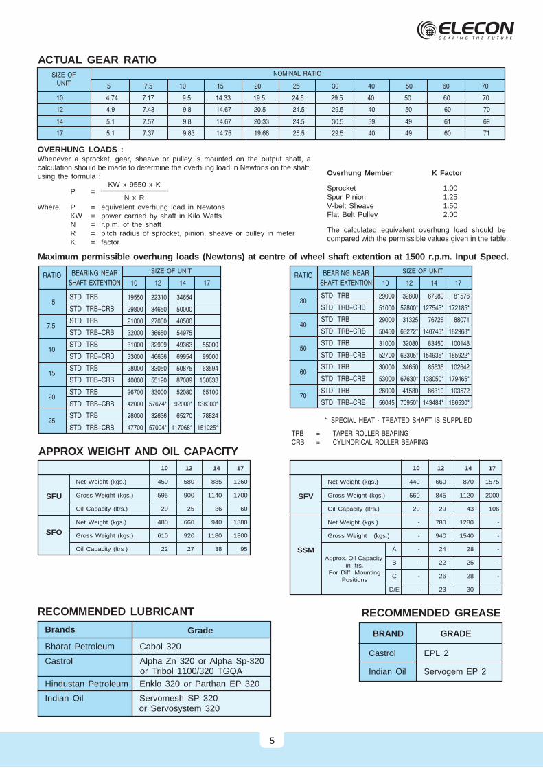
ACTUAL GEAR RATIONOMINAL RATIO
5 7.5 10 15 20 25 30 40 50 60 70
SIZE OFUNIT
12 4.9 7.43 9.8 14.67 20.5 24.5 29.5 40 50 60 70
14 5.1 7.57 9.8 14.67 20.33 24.5 30.5 39 49 61 69
17 5.1 7.37 9.83 14.75 19.66 25.5 29.5 40 49 60 71
10 4.74 7.17 9.5 14.33 19.5 24.5 29.5 40 50 60 70
Overhung Member K Factor
Sprocket 1.00Spur Pinion 1.25V-belt Sheave 1.50Flat Belt Pulley 2.00
The calculated equivalent overhung load should becompared with the permissible values given in the table.
OVERHUNG LOADS :Whenever a sprocket, gear, sheave or pulley is mounted on the output shaft, acalculation should be made to determine the overhung load in Newtons on the shaft,using the formula :
P =
Where, P = equivalent overhung load in NewtonsKW = power carried by shaft in Kilo WattsN = r.p.m. of the shaftR = pitch radius of sprocket, pinion, sheave or pulley in meterK = factor
KW x 9550 x K
N x R
Maximum permissible overhung loads (Newtons) at centre of wheel shaft extention at 1500 r.p.m. Input Speed.
* SPECIAL HEAT - TREATED SHAFT IS SUPPLIED
TRB = TAPER ROLLER BEARINGCRB = CYLINDRICAL ROLLER BEARING
5
7.5
10
15
20
25
RATIO BEARING NEAR
SHAFT EXTENTION
STD TRB
STD TRB+CRB
STD TRB
STD TRB+CRB
STD TRB
STD TRB+CRB
STD TRB
STD TRB+CRB
STD TRB
STD TRB+CRB
STD TRB
STD TRB+CRB
19550 22310 34654
29800 34650 50000
21000 27000 40500
32000 36650 54975
31000 32909 49363 55000
33000 46636 69954 99000
28000 33050 50875 63594
40000 55120 87089 130633
26700 33000 52080 65100
42000 57674* 92000* 138000*
28000 32636 65270 78824
47700 57004* 117068* 151025*
SIZE OF UNIT
10 12 14 17
5
30
40
50
60
70
RATIO BEARING NEAR
SHAFT EXTENTION
STD TRB
STD TRB+CRB
STD TRB
STD TRB+CRB
STD TRB
STD TRB+CRB
STD TRB
STD TRB+CRB
STD TRB
STD TRB+CRB
29000 32800 67980 81576
51000 57800* 127545* 172185*
29000 31325 76726 88071
50450 63272* 140745* 182968*
31000 32080 83450 100148
52700 63305* 154935* 185922*
30000 34650 85535 102642
53000 67630* 138050* 179465*
26000 41580 86310 103572
56045 70950* 143484* 186530*
SIZE OF UNIT
10 12 14 17
APPROX WEIGHT AND OIL CAPACITY
Net Weight (kgs.)
Gross Weight (kgs.)
Oil Capacity (ltrs.)
Net Weight (kgs.)
Gross Weight (kgs.)
Oil Capacity (ltrs )
12
580
900
25
660
920
27
10
450
595
20
480
610
22
14
885
1140
36
940
1180
38
17
1260
1700
60
1380
1800
95
SFU
SFO
1210 14 17
Net Weight (kgs.)
Gross Weight (kgs.)
Oil Capacity (ltrs.)
Net Weight (kgs.)
Gross Weight (kgs.)
A
B
C
D/E
24
22
26
23
-
-
-
-
28
25
28
30
660
845
29
780
940
440
560
20
-
-
870
1120
43
1280
1540
1575
2000
106
-
-
-
-
-
-
SFV
SSMApprox. Oil Capacity
in ltrs.For Diff. Mounting
Positions
Bharat Petroleum Cabol 320
Castrol Alpha Zn 320 or Alpha Sp-320 or Tribol 1100/320 TGQA
Hindustan Petroleum Enklo 320 or Parthan EP 320
Indian Oil Servomesh SP 320 or Servosystem 320
RECOMMENDED LUBRICANT
Brands Grade
RECOMMENDED GREASE
BRAND
Castrol
Indian Oil
EPL 2
Servogem EP 2
GRADE

PRODUCT SAFETY INFORMATION
General ELECON gear units will operate safety provided that they are selected, installed, used
and maintained property. As with any equipment consists of rotating swhafts andtransmitting power, adequate guarding is necessary to elimiate the possibility of physi-cal contact with rotating shafts or coupling.
Potential Hazards The following points should be noted and brought to attention to the persons involved
in the installation, use and maintenance of equipment.
1. For lifting of gearunit eye-bolts or lifting points (on larger units) should be used.
2. Check the grade and quantity of lubrication before commissioning. Read and carry out all instructions onlubricant plate and in the installation and maintenance manual literature.
3. Installation must be performed in accordance with the manufacturer’s instruction and be undertaken bysuitably qualified personnel.
4. Ensure the proper maintenance of gearboxes in operation. USE ONLY ELECON SPARES FOR GEAR-BOXES.
5. The oil level should be examined periodically, if required the oil should be filled again.
6. The operating speeds, transmitting powers, generated torques or the external loads must not exceed thedesign values.
7. The driving and the driven equipment must be correctly selected to ensure that the complete installation ofthe machinery will perform satisfactorily e.g. avoiding system critical speeds, system torsional vibration etc.
As improvement in designing are continuously being made, the details and dimensions are subject to alterationwithout notice.
ELECON ENGINEERING CO. LTD.POST BOX # 6, VALLABH VIDYANAGAR 388 120, GUJARAT, INDIATEL.: +91-2692-236513, 236520, 232890 FAX : +91-2692-236527
E-MAIL : [email protected] Site : http://www.elecon.com
Any other required information or clarification can be obtained by writing to :
6