Embed Size (px)
Citation preview

1EINC Data Sheet TA200137 Issue 2/C 7/7/06
Data Sheet
EINCNode Controller
EINC Node Controller
Description
The EINC, Ethernet Internetwork Node Controller, provides themeans by which the Building Management System network canincorporate an Ethernet network. The EINC operates at theinternetwork level, including the necessary support for WAN’s (e.g.TMN support). It also provides virtual CNCs which allow supervisoryor tool software running in PCs connected to the Ethernet networkto connect to the BMS system.
It is provided with a 10 BASE-T interface, and an AUI connectorwhich allows an alternative network transceiver to be used.
Features
• Facilitates use of Ethernet network in BMS system.• 10 BASE-T interface and AUI connector for alternative transceivers.• Four virtual CNCs for PC connection using Ethernet.• EINCs can build internetworks across routers.• Ethernet provides faster signalling rate.• Integration of BMS network into existing Ethernet system.• Automatic reporting of network population.• Network alarms available in 10 languages.• EEPROM retains configured data during power fail (no battery
required).
Physical
~
1 2 3 4 5 6 7 8 9 10
TX RX
OK
LAN
OK
TX RX
~230V
RDS/RS232 !MODEM24V
� � �
� � � � � � � 00.10.70.00.UD.BB
� �
S/No:Q3B____X73010003
� � � � � � Location
� � � � � � � 00.10.70.00.UD.BB
S/No:Q3B____X73010003EINC -400007096
� � � � � �
� � � � � � �
230Vac supplyconnector
power/watchdogLEDs
230 mm (9.06")Ethernet LEDs address/baud switch
current loopnetworkconnector
current loopnetwork LEDs
Ethernet (10BASE-T) connector Ethernet transceiver (AUI) connector
70 mm (2.76")
181
mm
(7.
13")
earth/groundbusbar
24 Vac supplyconnector
2 EINC Data Sheet TA200137 Issue 2/C 7/7/06
EINC Data Sheet
FUNCTIONALITYThe functionality of the EINC can be split into system, hardware, and firmware sections:
SYSTEM
The EINC acts as an interface between parts of an IQ network running over IQ system current loop, and Ethernet. It acts like an INC,but it enables an Ethernet network to be used to carry the internetwork. It also enables a current loop internetwork to be extendedonto an Ethernet network. To enable this an EINC can operate in one of two modes:
INC modeInternetwork Extension mode.
The mode of operation is determined by the address set on its address switch. When set to a value less than 100 it will operate inINC mode when set to a value greater than or equal to 100 it will operate in Internetwork Extension mode.
INC Mode
When operating in INC mode it enables an internetwork running on an Ethernet network and a Lan running on a current loop networkto be joined together to form a single IQ network as shown below.
OK
Tx Rx
230 V1 2 3 4 5 6 83 4 5
7 9 10 1124V 24V
AC24VAC
24VAC
OK
Tx Rx
230 V1 2 3 4 5 6 83 4 5
7 9 10 1124V 24V
AC24VAC
24VAC
IQ3 IQ3
IQ3 IQ3
IQView
EINC
IQ2 IQ2
IQ Current Loop Lan
Ethernet
Internetwork(on Ethernet)
Lan(on Ethernet)
Lan(on Ethernet)
Note that when operating in this mode it is not possible to haveanother internetworking device (e.g. INC) on the IQ system currentloop.
The EINC will build an internetwork with other EINCs,3xtend/EINCLs, LINCs, IQ3s, NXIPs or IQViews connected tothe same Ethernet network. The LAN number of the Lan connectedto the EINC’s IQ system current loop is defined by the EINC’saddress switch. This Lan will consist of the devices connected tothe IQ system current loop to which the EINC is connected; it willalso contain the EINC’s virtual CNCs, plus the EINC itself, whichalways has address 126.
EINC
CNC1
EINC’s Local Lan
INC
CNC2 CNC3
CNC4
OK
Tx Rx
230 V1 2 3 4 5 6 83 4 5
7 9 10 1124V 24V
AC24VAC
24VAC
IQ
OK
Tx Rx
230 V1 2 3 4 5 6 83 4 5
7 9 10 1124V 24V
AC24VAC
24VAC
IQ
126
OK
Tx Rx
230 V1 2 3 4 5 6 83 4 5
7 9 10 1124V 24V
AC24VAC
24VAC
OK
Tx Rx
230 V1 2 3 4 5 6 83 4 5
7 9 10 1124V 24V
AC24VAC
24VAC
Internetwork Extension Mode
When operating in internetwork extension mode the EINC enables an internetwork running on an Ethernet network and a internetworkrunning on an IQ system current loop network to be joined together to form a single IQ internetwork as shown below.
IQ3 IQ3
IQ3 IQ3
IQView
EINC
IQ Current Loop Lan
Ethernet
Internetwork
Lan(on Ethernet)
Lan(on Ethernet)
INC
IQ Current LoopInternetwork
In the diagram an internetwork on Ethernet is joined to aninternetwork on an IQ current loop using an EINC to interfacebetween the Ethernet network and the IQ system current loop.
3EINC Data Sheet TA200137 Issue 2/C 7/7/06
Data Sheet EINC
Virtual CNCs
The EINC’s firmware incorporates four virtual CNCs that enable the connection between a PC running supervisor/tool software andthe IQ network to be made over Ethernet to the virtual CNC. They also enable alarms generated from IQs or other devices to betransmitted to a PC running 963. In order to do this each of the virtual CNCs can act in on of two modes:
Supervisor modeAlarm mode
For a virtual CNC to operate, its cnc Address must be set up using IPTool or in configuration mode. The virtual CNC is switched froma supervisor mode to alarm mode by setting up an alarm IP address or host name in the virtual CNC module. Once enabled the virtualCNCs appear to be located on the EINC’s local Lan, and will respond to Lan mapping in this way.
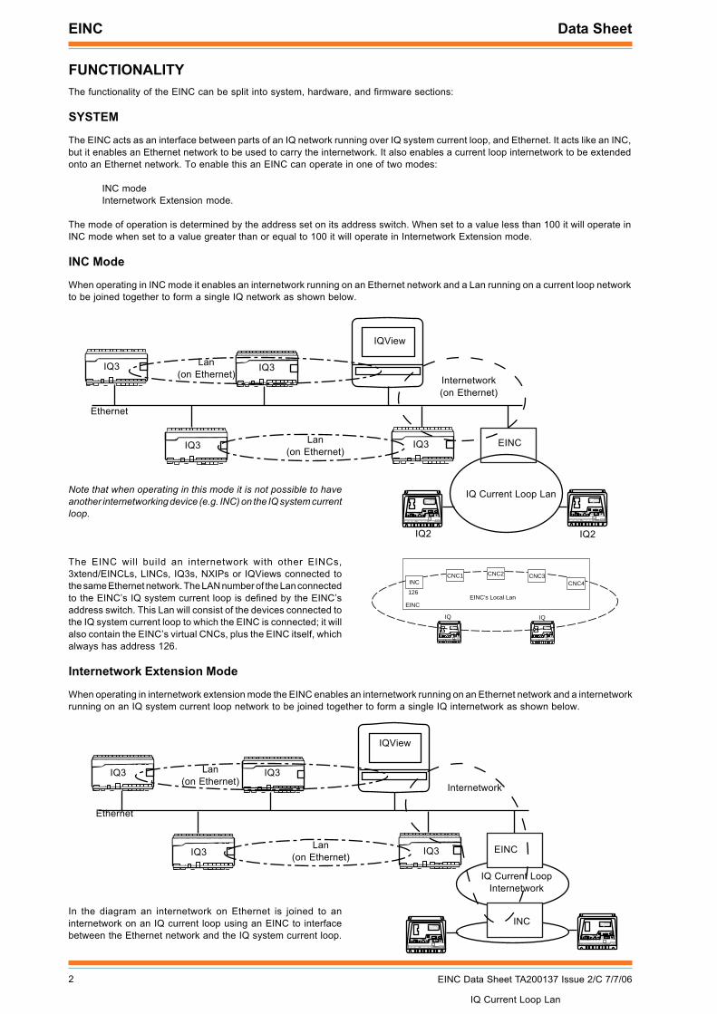
Supervisor ModeThis enables the Ethernet network to be used as a connectionbetween a PC running supervisory or tool software and the virtualCNC (rather than normal RS232, device to CNC, interface). Thesupervisor connects to the CNC by using the EINC’s IP addressand the port address set up in the virtual CNC module making apermanent connection to the virtual CNC. This enables thesupervisor/tool to communicate with devices on the IQ network,and for those devices to communicate with it.
The 963 can make a connection to the virtual CNC wheninformation is required, treating each connection as a separatesite. However, the connection will only allow the virtual CNC tosend alarms back to the supervisor when the supervisor isconnected. If alarms need to be sent independently of thesupervisor being connected then a virtual CNC in alarm modemust be used.
EINC
CNC3CNC2CNC1
EINC’s Local Lan
INC CNC4
Tempory EthernetConnection
963
EINC
CNC3CNC2CNC1
EINC’s Local Lan
INC CNC4
Ethernet
Supervisor/Tool
24
Connection to virtual CNC
In the diagram above the supervisor/tool connects to the EINC’svirtual CNC2 over Ethernet, and will have will have a Lan addressof 20 and a network address of 24 on the IQ network.
Alarm ModeThe Alarm mode of a virtual CNC enables alarms generated fromIQs or other devices to be transmitted to a PC running 963connected to the Ethernet where the connection to the virtualCNC is of a temporary nature. An IQ can send its alarms to thevirtual CNC using normal Lan/device addressing, and the virtualCNC will forward the alarms to the PC using the Port Address andthe Alarm IP address, specified in the virtual CNC. The 963listens for alarms on the specified port, and retrieves the siteidentities, Lan numbers, and device addresses of any alarms itreceives so that it can process them further.
In the diagram right the 963 is able to connect to the site on whichthe EINC is situated, using a temporary connection to virtualCNC 1 which is in supervisor mode. Virtual CNC 2 is operatingin alarm mode and set to forward alarms it receives to the IPaddress of the 963.
Connection to virtual CNC with alarms sent by virtual CNC inalarm mode.
Building Internetworks On Ethernet
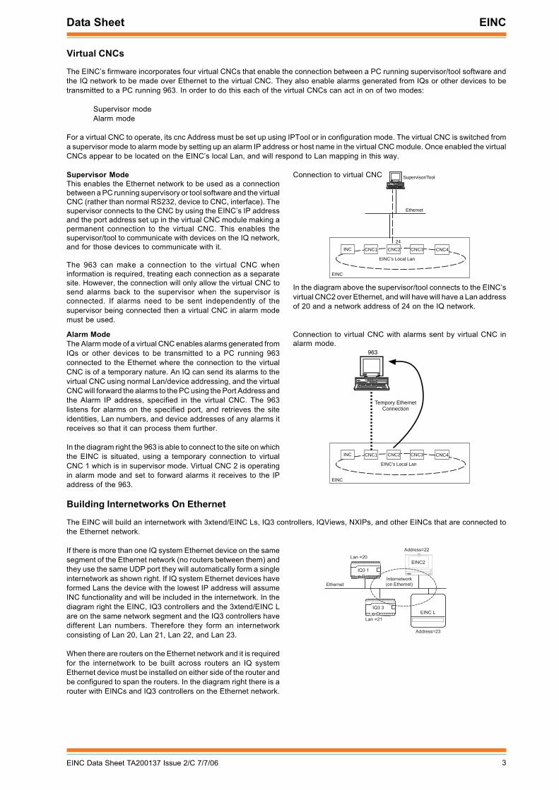
The EINC will build an internetwork with 3xtend/EINC Ls, IQ3 controllers, IQViews, NXIPs, and other EINCs that are connected tothe Ethernet network.
If there is more than one IQ system Ethernet device on the samesegment of the Ethernet network (no routers between them) andthey use the same UDP port they will automatically form a singleinternetwork as shown right. If IQ system Ethernet devices haveformed Lans the device with the lowest IP address will assumeINC functionality and will be included in the internetwork. In thediagram right the EINC, IQ3 controllers and the 3xtend/EINC Lare on the same network segment and the IQ3 controllers havedifferent Lan numbers. Therefore they form an internetworkconsisting of Lan 20, Lan 21, Lan 22, and Lan 23.
When there are routers on the Ethernet network and it is requiredfor the internetwork to be built across routers an IQ systemEthernet device must be installed on either side of the router andbe configured to span the routers. In the diagram right there is arouter with EINCs and IQ3 controllers on the Ethernet network.
� � � �
� � � �
� � � � � � � � �
� � � � � � � � � � � �
� � � � � �
EINC
� � �
� � � � � � � �
� � � � � !
� � � � " " �
� � � � �
� � � � " " � �
4 EINC Data Sheet TA200137 Issue 2/C 7/7/06
EINC Data Sheet
Building Internetworks On Ethernet (Continued)
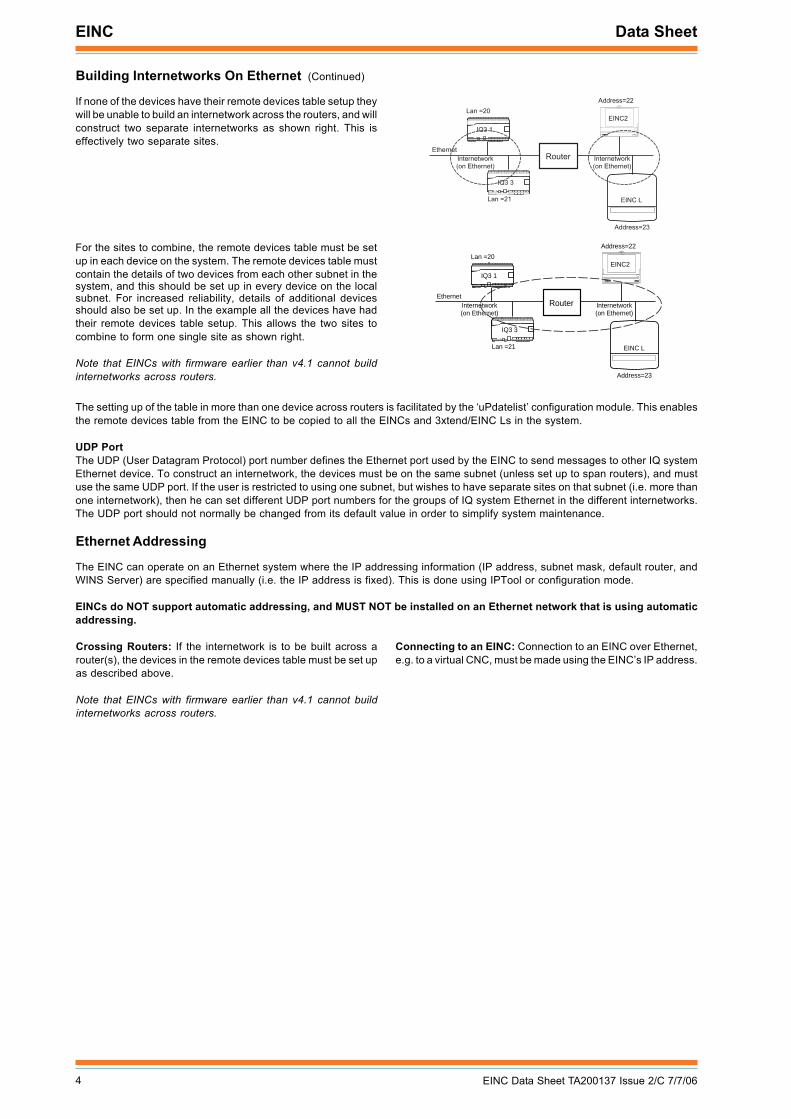
If none of the devices have their remote devices table setup theywill be unable to build an internetwork across the routers, and willconstruct two separate internetworks as shown right. This iseffectively two separate sites.
For the sites to combine, the remote devices table must be setup in each device on the system. The remote devices table mustcontain the details of two devices from each other subnet in thesystem, and this should be set up in every device on the localsubnet. For increased reliability, details of additional devicesshould also be set up. In the example all the devices have hadtheir remote devices table setup. This allows the two sites tocombine to form one single site as shown right.
Note that EINCs with firmware earlier than v4.1 cannot buildinternetworks across routers.
� � � �
� � � �
� � � � � � � � �
� � � � � � � � � � � �
� � � � � �
EINC
� � �
� � � � � � � �
� � � � � !
� � � � " " �
� � � � �
� � � � " " � �
# � $ � � � � � � � � � � �
� � � � � � � � � � � �
IQ3 1
IQ3 3
Internetwork(on Ethernet)
Lan =21
EINC
EINC2
Ethernet
Lan =20
Address=22
EINC L
Address=23
Router Internetwork(on Ethernet)
The setting up of the table in more than one device across routers is facilitated by the ‘uPdatelist’ configuration module. This enablesthe remote devices table from the EINC to be copied to all the EINCs and 3xtend/EINC Ls in the system.
UDP PortThe UDP (User Datagram Protocol) port number defines the Ethernet port used by the EINC to send messages to other IQ systemEthernet device. To construct an internetwork, the devices must be on the same subnet (unless set up to span routers), and mustuse the same UDP port. If the user is restricted to using one subnet, but wishes to have separate sites on that subnet (i.e. more thanone internetwork), then he can set different UDP port numbers for the groups of IQ system Ethernet in the different internetworks.The UDP port should not normally be changed from its default value in order to simplify system maintenance.
Ethernet Addressing
The EINC can operate on an Ethernet system where the IP addressing information (IP address, subnet mask, default router, andWINS Server) are specified manually (i.e. the IP address is fixed). This is done using IPTool or configuration mode.
EINCs do NOT support automatic addressing, and MUST NOT be installed on an Ethernet network that is using automaticaddressing.
Crossing Routers: If the internetwork is to be built across arouter(s), the devices in the remote devices table must be set upas described above.
Note that EINCs with firmware earlier than v4.1 cannot buildinternetworks across routers.
Connecting to an EINC: Connection to an EINC over Ethernet,e.g. to a virtual CNC, must be made using the EINC’s IP address.
5EINC Data Sheet TA200137 Issue 2/C 7/7/06
Data Sheet EINC
HARDWARE
Box: The EINC is housed in an IP30 network box , which providesa plastic 230 mm (9.06") x 181 mm (7.13") x 70 mm (2.76") IP30enclosure suitable for three point mounting using 8 mm (0.31")holes. An optional metal enclosure with cable glanding knockouts(ENCLS/MBOX) is available.
Power: The EINC is available in two different power versions24V and 230V. The 24V version requires 24 Vac. The 230Vversion (/230) (not available in USA) requires 230 Vac inputpower at 50 or 60 Hz. The maximum consumption is 8 VA.
Fusing: The 230 Vac version (not available in USA) is protectedby 125 mA (T), 250 V, 20 mm supply fuse, the 24 Vac version isprotected by 1.6 A, 20 mm supply fuse.
IQ Current Loop Network: The network connection is a 4 wide setof 2 part terminals, suitable for 2 wire cables. The standard currentloop node features are included (Lan OK, TX, and RX indicators,bypass relays, network alarm generation).
Network bypass relay: In order the current loop Lan continuesto operate if the EINC fails, a set of node bypass relays is fittedto maintain network integrity in the event failure of the node’spower supply, or failure of the node itself. The bypassing of anode will be recognised by the downstream node, and reportedas a Lan Changed alarm.
Connectors: Two part connectors are used throughout to facilitatewiring. A busbar is provided for screen termination.
Data Backup: The EINC uses EEPROM to hold configurationdata. This is non-volatile to power failure without need for abattery.
Address Switch: The EINC device address on the local Lan isset to 126. The Lan number (1, 4 to 9, 11 to 99) is selected by theaddress switch poles 1 to 7. It must be set to a Lan numberunique on the internetwork. An address setting <100 sets theEINC’s mode of operation as INC mode and =>100 set the modeof operation internetwork extension mode.
Baud Rate Switch: The baud rate on the current loop networkis set by address/baud rate switch poles 8 to 10. It must be setto match other nodes on the Lan. It may be set to 1k2, 9k6, or19k2 baud. It may also be set to 38k4 baud by selecting both 1k2and 19k2, although this rate can only be used with other node 2devices (e.g. INC2).
Reset: Setting both the address and baud rate switches to zerofor more than 3 seconds with power applied will reset theconfiguration parameters to default values. Defaults are:
Address module (see list in firmware section)User module (clear)Router (clear)Virtual CNCs (clear)Remote EINCs (clear)
Transceivers: The EINC has two Ethernet connector, the 10 BASE-T connector and the AUI connector, but only one connector maybe used at a time. The unit will automatically detect which connector is in use.
The 10 BASE-T network uses twisted pair cable (to IEEE 802.3)and the EINC can run up to 10 Mbps. The maximum distancebetween the node and the hub is 100 m (109 yds). The EINCshould be connected to the hub using Cat 5e unshielded orshielded (UTP or FTP) cable and RJ45 plugs (shielded orunshielded appropriate to the cable).
The Attachment Unit Interface (AUI) connector is a 15-way Dtype. It is a standard connector for connection either directly, orindirectly by a drop cable, to a transceiver module. This enablesuse of other Ethernet media such as 10 BASE-2 (co-axial thinnet) or FOR/RL (fibre-optic cable). The interface can supply 12 Vdcat a maximum of 400 mA to the transceiver module.
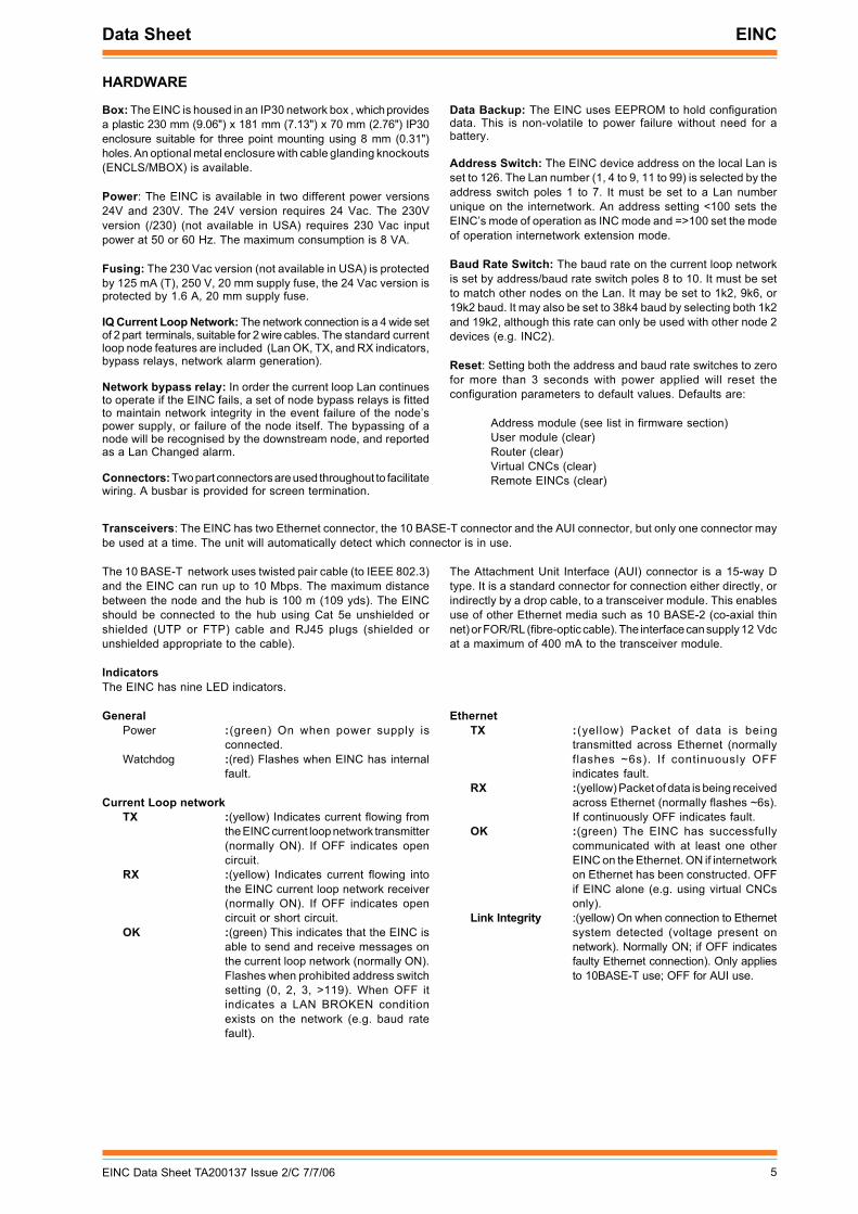
IndicatorsThe EINC has nine LED indicators.
GeneralPower :(green) On when power supply is
connected.Watchdog :(red) Flashes when EINC has internal
fault.
Current Loop networkTX :(yellow) Indicates current flowing from
the EINC current loop network transmitter(normally ON). If OFF indicates opencircuit.
RX :(yellow) Indicates current flowing intothe EINC current loop network receiver(normally ON). If OFF indicates opencircuit or short circuit.
OK :(green) This indicates that the EINC isable to send and receive messages onthe current loop network (normally ON).Flashes when prohibited address switchsetting (0, 2, 3, >119). When OFF itindicates a LAN BROKEN conditionexists on the network (e.g. baud ratefault).
EthernetTX :(yellow) Packet of data is being
transmitted across Ethernet (normallyflashes ~6s). If continuously OFFindicates fault.
RX :(yellow) Packet of data is being receivedacross Ethernet (normally flashes ~6s).If continuously OFF indicates fault.
OK :(green) The EINC has successfullycommunicated with at least one otherEINC on the Ethernet. ON if internetworkon Ethernet has been constructed. OFFif EINC alone (e.g. using virtual CNCsonly).
Link Integrity :(yellow) On when connection to Ethernetsystem detected (voltage present onnetwork). Normally ON; if OFF indicatesfaulty Ethernet connection). Only appliesto 10BASE-T use; OFF for AUI use.
6 EINC Data Sheet TA200137 Issue 2/C 7/7/06
EINC Data Sheet
FIRMWARE
The EINC’s firmware consists of a number of configuration modules (see table below) similar to the ones used in IQ controllers thatenable EINC’s operation to be specified. These modules need to be set up as required before the EINC will operate correctly.
The initial configuration is best done using IPTool over Ethernet. This allows the configuration of the IP address, subnet mask, UDPport, Lan and network address, default router, virtual CNCs, and the remote devices table. The configuration of other moduleparameters must be done using the EINC’s configuration mode which provides access to all of the EINC’s parameters. Configurationmode is a built-in feature enabling the modules to be setup using the network (including across the internetwork), using any IQ systemconfiguration utility.
When accessing the EINC with IPTool it can be identified from the list of devices by its MAC address. The EINC can be accessedin configuration mode using any IQ system configuration utility connected to the IQ network. This connection can be made usingEthernet, or the current loop. A local PC may be connected using the Ethernet either by using an adjacent hub, or by direct connectionusing a standard Ethernet cable in conjunction with a crossover adapter (XCITE/XA) and then by using one of the EINC’s virtual CNCs.Once the configuration utility has connected to the IQ network the EINC will be located from its local Lan at address 126 on Lan 0,and from the internetwork by device address 126 on its Lan number.
Configuration Mode
When an EINC is accessed in configuration mode the top-level configuration mode menu is as follows:
Connecting to OS 126 Lan 0EINCUser addRes rouTer virtualCncs remoteEincs uPdatelist=?
Note that if Ethernet is not connected, the following warning is given:
*** WARNING - NO ETHERNET SIGNAL DETECTED ***
The required options are selected by entering the relevant upper case letter and pressing ENTER. If a value has been changedX+ENTER will confirm it and return to the top menu, whereas Q+ENTER will quit and return with the value unchanged. Configurationmode may be protected by a password that will stop any changes being made until a valid password is entered.
Address Module
The address module stores the EINC’s addressing information. It has the following parameters:
Module Type Modue Identifier Number of Modules
Address R 1
Remote EINCs E 20
Router T 1
Updatelist P 1
User U 1
Virtual CNC C 4
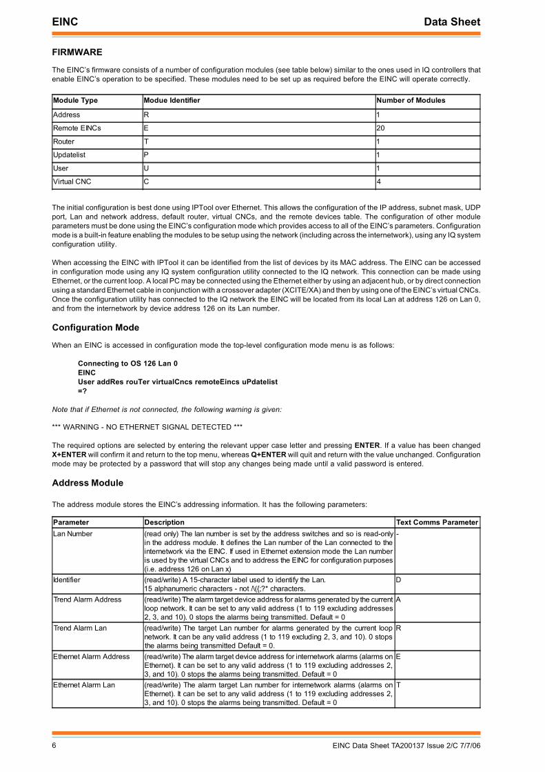
Parameter Description Text Comms ParameterLan Number (read only) The lan number is set by the address switches and so is read-only
in the address module. It defines the Lan number of the Lan connected to theinternetwork via the EINC. If used in Ethernet extension mode the Lan numberis used by the virtual CNCs and to address the EINC for configuration purposes(i.e. address 126 on Lan x)
-
Identifier (read/write) A 15-character label used to identify the Lan.15 alphanumeric characters - not /\({;?* characters.
D
Trend Alarm Address (read/write) The alarm target device address for alarms generated by the currentloop network. It can be set to any valid address (1 to 119 excluding addresses2, 3, and 10). 0 stops the alarms being transmitted. Default = 0
A
Trend Alarm Lan (read/write) The target Lan number for alarms generated by the current loopnetwork. It can be any valid address (1 to 119 excluding 2, 3, and 10). 0 stopsthe alarms being transmitted Default = 0.
R
Ethernet Alarm Address (read/write) The alarm target device address for internetwork alarms (alarms onEthernet). It can be set to any valid address (1 to 119 excluding addresses 2,3, and 10). 0 stops the alarms being transmitted. Default = 0
E
Ethernet Alarm Lan (read/write) The alarm target Lan number for internetwork alarms (alarms onEthernet). It can be set to any valid address (1 to 119 excluding addresses 2,3, and 10). 0 stops the alarms being transmitted. Default = 0
T
7EINC Data Sheet TA200137 Issue 2/C 7/7/06
Data Sheet EINC
Address Module (Continued)
Remote EINC Modules
The remote EINC modules store details of other devices that are to form part of the internetwork on Ethernet, allowing theinternetwork to be built across routers. They form the remote devices table; each module is one entry in the table. There are 20modules enabling up to 20 remote devices to be specified.
The remote devices table must contain the details of two devices on the internetwork from each other subnet and be set up in everydevice on the local subnet. The devices must be specified using their IP address and subnet mask and the devices should be thosewith the lowest IP address. For increased reliability, details of additional devices should also be set up.
Router Module
The router modules specifies the IP address of the router to which messages are sent if the destination address is not on the localsubnet. It should be set to the IP address of a router on the same subnet as the EINC. It must be specified if the EINC is to buildan internetwork across routers, or if one of the virtual CNCs is to be used by a PC connected to an Ethernet subnet the other sideof a router.
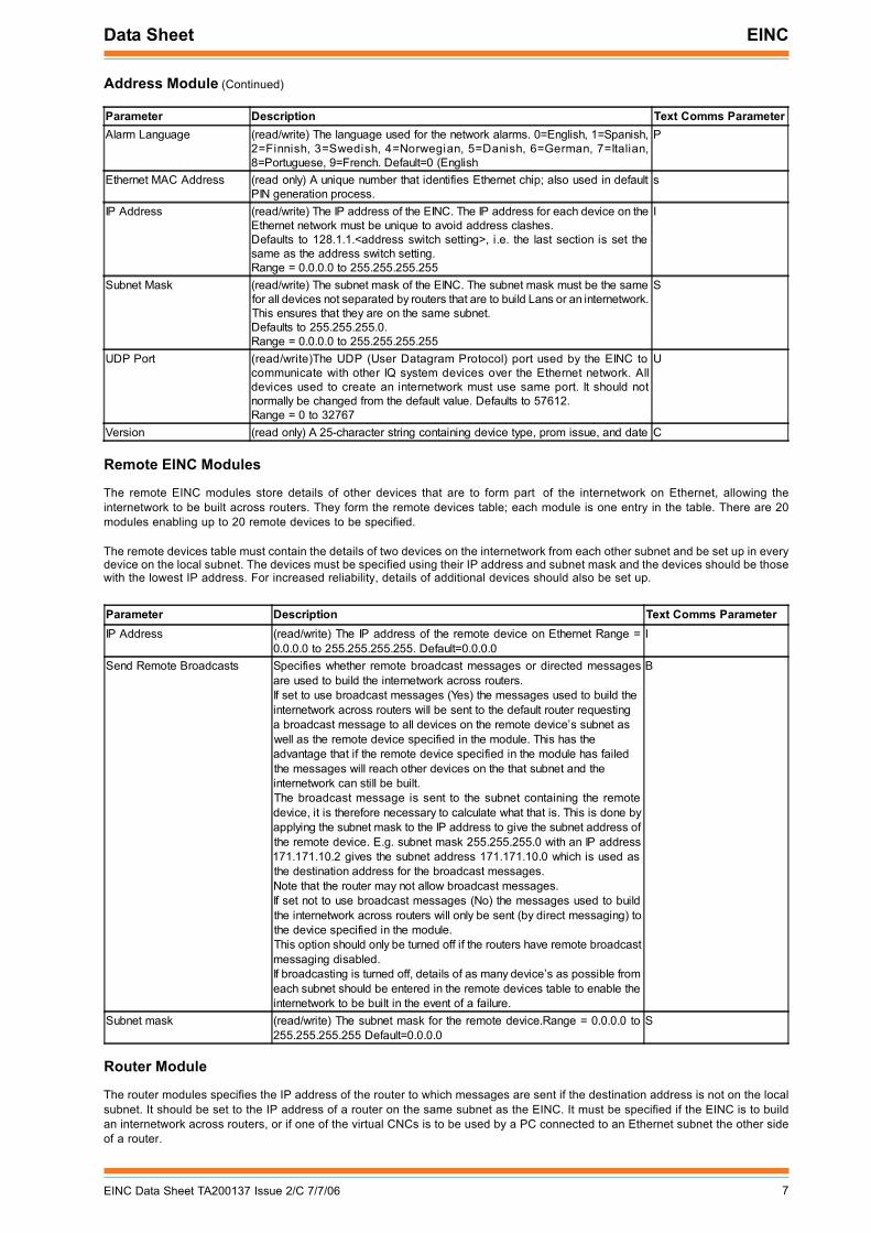
Parameter Description Text Comms ParameterAlarm Language (read/write) The language used for the network alarms. 0=English, 1=Spanish,
2=Finnish, 3=Swedish, 4=Norwegian, 5=Danish, 6=German, 7=Italian,8=Portuguese, 9=French. Default=0 (English
P
Ethernet MAC Address (read only) A unique number that identifies Ethernet chip; also used in defaultPIN generation process.
s
IP Address (read/write) The IP address of the EINC. The IP address for each device on theEthernet network must be unique to avoid address clashes.Defaults to 128.1.1.<address switch setting>, i.e. the last section is set thesame as the address switch setting.Range = 0.0.0.0 to 255.255.255.255
I
Subnet Mask (read/write) The subnet mask of the EINC. The subnet mask must be the samefor all devices not separated by routers that are to build Lans or an internetwork.This ensures that they are on the same subnet.Defaults to 255.255.255.0.Range = 0.0.0.0 to 255.255.255.255
S
UDP Port (read/write)The UDP (User Datagram Protocol) port used by the EINC tocommunicate with other IQ system devices over the Ethernet network. Alldevices used to create an internetwork must use same port. It should notnormally be changed from the default value. Defaults to 57612.Range = 0 to 32767
U
Version (read only) A 25-character string containing device type, prom issue, and date C
Parameter Description Text Comms ParameterIP Address (read/write) The IP address of the remote device on Ethernet Range =
0.0.0.0 to 255.255.255.255. Default=0.0.0.0I
Send Remote Broadcasts Specifies whether remote broadcast messages or directed messagesare used to build the internetwork across routers.If set to use broadcast messages (Yes) the messages used to build theinternetwork across routers will be sent to the default router requestinga broadcast message to all devices on the remote device’s subnet aswell as the remote device specified in the module. This has theadvantage that if the remote device specified in the module has failedthe messages will reach other devices on the that subnet and theinternetwork can still be built.The broadcast message is sent to the subnet containing the remotedevice, it is therefore necessary to calculate what that is. This is done byapplying the subnet mask to the IP address to give the subnet address ofthe remote device. E.g. subnet mask 255.255.255.0 with an IP address171.171.10.2 gives the subnet address 171.171.10.0 which is used asthe destination address for the broadcast messages.Note that the router may not allow broadcast messages.If set not to use broadcast messages (No) the messages used to buildthe internetwork across routers will only be sent (by direct messaging) tothe device specified in the module.This option should only be turned off if the routers have remote broadcastmessaging disabled.If broadcasting is turned off, details of as many device’s as possible fromeach subnet should be entered in the remote devices table to enable theinternetwork to be built in the event of a failure.
B
Subnet mask (read/write) The subnet mask for the remote device.Range = 0.0.0.0 to255.255.255.255 Default=0.0.0.0
S
8 EINC Data Sheet TA200137 Issue 2/C 7/7/06
EINC Data Sheet
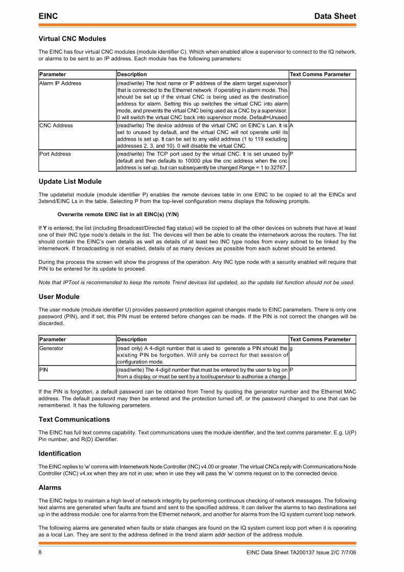
Virtual CNC Modules
The EINC has four virtual CNC modules (module identifier C). Which when enabled allow a supervisor to connect to the IQ network,or alarms to be sent to an IP address. Each module has the following parameters:
Parameter Description Text Comms ParameterGenerator (read only) A 4-digit number that is used to generate a PIN should the
existing PIN be forgotten. Will only be correct for that session ofconfiguration mode.
g
PIN (read/write) The 4-digit number that must be entered by the user to log onfrom a display, or must be sent by a tool/supervisor to authorise a change.
P
Parameter Description Text Comms ParameterAlarm IP Address (read/write) The host name or IP address of the alarm target supervisor
that is connected to the Ethernet network if operating in alarm mode. Thisshould be set up if the virtual CNC is being used as the destinationaddress for alarm. Setting this up switches the virtual CNC into alarmmode, and prevents the virtual CNC being used as a CNC by a supervisor.0 will switch the virtual CNC back into supervisor mode. Default=Unused
I
CNC Address (read/write) The device address of the virtual CNC on EINC’s Lan. It isset to unused by default, and the virtual CNC will not operate until itsaddress is set up. It can be set to any valid address (1 to 119 excludingaddresses 2, 3, and 10). 0 will disable the virtual CNC.
A
Port Address (read/write) The TCP port used by the virtual CNC. It is set unused bydefault and then defaults to 10000 plus the cnc address when the cncaddress is set up, but can subsequently be changed.Range = 1 to 32767.
P
Update List Module
The updatelist module (module identifier P) enables the remote devices table in one EINC to be copied to all the EINCs and3xtend/EINC Ls in the table. Selecting P from the top-level configuration menu displays the following prompts.
Overwrite remote EINC list in all EINC(s) (Y/N)
If Y is entered, the list (including Broadcast/Directed flag status) will be copied to all the other devices on subnets that have at leastone of their INC type node’s details in the list. The devices will then be able to create the internetwork across the routers. The listshould contain the EINC’s own details as well as details of at least two INC type nodes from every subnet to be linked by theinternetwork. If broadcasting is not enabled, details of as many devices as possible from each subnet should be entered.
During the process the screen will show the progress of the operation. Any INC type node with a security enabled will require thatPIN to be entered for its update to proceed.
Note that IPTool is recommended to keep the remote Trend devices list updated, so the update list function should not be used.
User Module
The user module (module identifier U) provides password protection against changes made to EINC parameters. There is only onepassword (PIN), and if set, this PIN must be entered before changes can be made. If the PIN is not correct the changes will bediscarded.
If the PIN is forgotten, a default password can be obtained from Trend by quoting the generator number and the Ethernet MACaddress. The default password may then be entered and the protection turned off, or the password changed to one that can beremembered. It has the following parameters.
Text Communications
The EINC has full text comms capability. Text communications uses the module identifier, and the text comms parameter. E.g. U(P)Pin number, and R(D) iDentifier.
Identification
The EINC replies to 'w' comms with Internetwork Node Controller (INC) v4.00 or greater. The virtual CNCs reply with Communications NodeController (CNC) v4.xx when they are not in use; when in use they will pass the 'w' comms request on to the connected device.
Alarms
The EINC helps to maintain a high level of network integrity by performing continuous checking of network messages. The followingtext alarms are generated when faults are found and sent to the specified address. It can deliver the alarms to two destinations setup in the address module: one for alarms from the Ethernet network, and another for alarms from the IQ system current loop network.
The following alarms are generated when faults or state changes are found on the IQ system current loop port when it is operatingas a local Lan. They are sent to the address defined in the trend alarm addr section of the address module.
9EINC Data Sheet TA200137 Issue 2/C 7/7/06
Data Sheet EINC
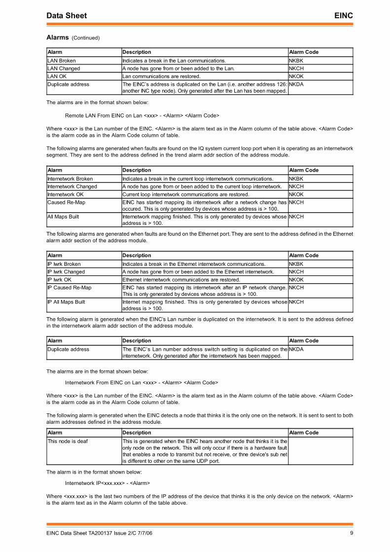
Alarms (Continued)
Alarm Description Alarm CodeLAN Broken Indicates a break in the Lan communications. NKBKLAN Changed A node has gone from or been added to the Lan. NKCHLAN OK Lan communications are restored. NKOKDuplicate address The EINC’s address is duplicated on the Lan (i.e. another address 126:
another INC type node). Only generated after the Lan has been mapped.NKDA
Alarm Description Alarm CodeInternetwork Broken Indicates a break in the current loop internetwork communications. NKBKInternetwork Changed A node has gone from or been added to the current loop internetwork. NKCHInternetwork OK Current loop internetwork communications are restored. NKOKCaused Re-Map EINC has started mapping its internetwork after a network change has
occured. This is only generated by devices whose address is > 100.NKCH
All Maps Built Internetwork mapping finished. This is only generated by devices whoseaddress is > 100.
NKCH
Alarm Description Alarm CodeIP Iwrk Broken Indicates a break in the Ethernet internetwork communications. NKBKIP Iwrk Changed A node has gone from or been added to the Ethernet internetwork. NKCHIP Iwrk OK Ethernet internetwork communications are restored. NKOKIP Caused Re-Map EINC has started mapping its internetwork after an IP network change.
This is only generated by devices whose address is > 100.NKCH
IP All Maps Built Internet mapping finished. This is only generated by devices whoseaddress is > 100.
NKCH
Alarm Description Alarm CodeDuplicate address The EINC’s Lan number address switch setting is duplicated on the
internetwork. Only generated after the internetwork has been mapped.NKDA
The alarms are in the format shown below:
Remote LAN From EINC on Lan <xxx> - <Alarm> <Alarm Code>
Where <xxx> is the Lan number of the EINC. <Alarm> is the alarm text as in the Alarm column of the table above. <Alarm Code>is the alarm code as in the Alarm Code column of table.
The following alarms are generated when faults are found on the IQ system current loop port when it is operating as an internetworksegment. They are sent to the address defined in the trend alarm addr section of the address module.
The following alarms are generated when faults are found on the Ethernet port. They are sent to the address defined in the Ethernetalarm addr section of the address module.
The following alarm is generated when the EINC’s Lan number is duplicated on the internetwork. It is sent to the address definedin the internetwork alarm addr section of the address module.
The alarms are in the format shown below:
Internetwork From EINC on Lan <xxx> - <Alarm> <Alarm Code>
Where <xxx> is the Lan number of the EINC. <Alarm> is the alarm text as in the Alarm column of the table above. <Alarm Code>is the alarm code as in the Alarm Code column of table.
The following alarm is generated when the EINC detects a node that thinks it is the only one on the network. It is sent to sent to bothalarm addresses defined in the address module.
Alarm Description Alarm CodeThis node is deaf This is generated when the EINC hears another node that thinks it is the
only node on the network. This will only occur if there is a hardware faultthat enables a node to transmit but not receive, or thne device's sub netis different to other on the same UDP port.
The alarm is in the format shown below:
Internetwork IP<xxx.xxx> - <Alarm>
Where <xxx.xxx> is the last two numbers of the IP address of the device that thinks it is the only device on the network. <Alarm>is the alarm text as in the Alarm column of the table above.
10 EINC Data Sheet TA200137 Issue 2/C 7/7/06
EINC Data Sheet
�
� � � � � � � � � � � � � � � �
�
� � � � � % $ "
�
�
�
�
�
�
�
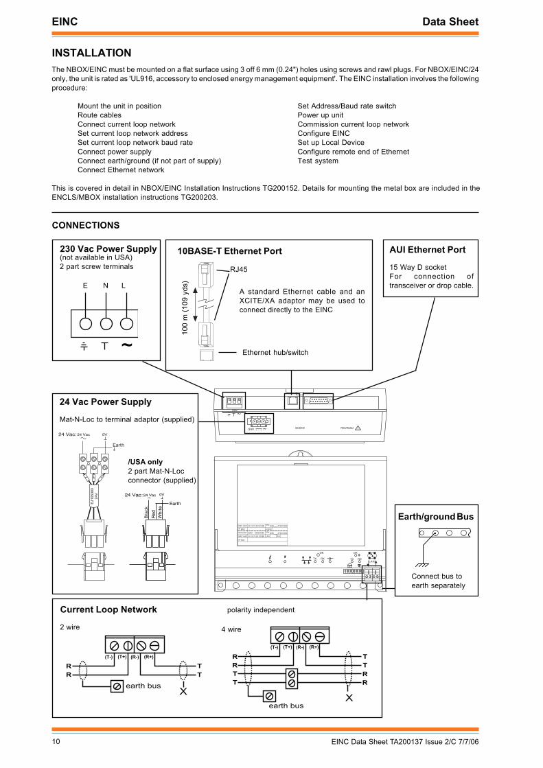
INSTALLATIONThe NBOX/EINC must be mounted on a flat surface using 3 off 6 mm (0.24") holes using screws and rawl plugs. For NBOX/EINC/24only, the unit is rated as 'UL916, accessory to enclosed energy management equipment'. The EINC installation involves the followingprocedure:
Mount the unit in positionRoute cablesConnect current loop networkSet current loop network addressSet current loop network baud rateConnect power supplyConnect earth/ground (if not part of supply)Connect Ethernet network
Set Address/Baud rate switchPower up unitCommission current loop networkConfigure EINCSet up Local DeviceConfigure remote end of EthernetTest system
This is covered in detail in NBOX/EINC Installation Instructions TG200152. Details for mounting the metal box are included in theENCLS/MBOX installation instructions TG200203.
230 Vac Power Supply(not available in USA)2 part screw terminals
E N L
Current Loop Network
2 wire 4 wire
AUI Ethernet Port
15 Way D socketFor connection oftransceiver or drop cable.
/USA only2 part Mat-N-Locconnector (supplied)
Earth/ground Bus
Connect bus toearth separately
polarity independent
CONNECTIONS
10BASE-T Ethernet Port
100
m (1
09 y
ds)
RJ45
Ethernet hub/switch
A standard Ethernet cable and anXCITE/XA adaptor may be used toconnect directly to the EINC
24 Vac Power Supply
Mat-N-Loc to terminal adaptor (supplied)
�
1 2 3 4 5 6 7 8 9 10
TX RX
OK
LAN
OK
TX RX
~230V
RDS/RS232 !MODEM
~
24V
� � �
� � � � � � � 00.10.70.00.UD.BB
� �
S/No:Q3B____X73010003
� � � � � � Location
� � � � � � � 00.10.70.00.UD.BB
S/No:Q3B____X73010003EINC -400007096
� � � � � �
� � � � � � �
EJ1
0538
324
V
24 Vac:24 Vac
Earth
0V
24 Vac:24 Vac
Earth
Bla
ck
Red
Wh
ite
0V~
��
� � � �
� � � � � % $ "
�
� � � � � � � � � � � �
� �
11EINC Data Sheet TA200137 Issue 2/C 7/7/06
Data Sheet EINC
COMPATIBILITY
Supervisors/Displays: 963 v2.1, 915MDS >v3, 916, IQViewUtility software: SET v6 (including IPTool software)Controllers: IQ3 controllers and IQ1, IQ2. Any IQ251 on the system must be firmware version 1.2 or later and an
IQ241 must be firmware version 1.2M or later.Ethernet Nodes: Compatible with NXIP and 3xtend/EINC L providing it is not used in an automatic IP addressing
environment. An ANC+, AND, or XN28 on the internetwork must be firmware version 2.5 or later andan MNC on the internetwork must be firmware version 2.54 or later (any TMN is OK). The 38k4 baudrate is only compatible with other node 2 devices (e.g. INC2).
Routers: EINC version 4.2 is required to build internetworks across routers.Automatic Addressing: Must not be used in an automatic IP addressing environment.
MAINTENANCEReplacement of the fuse is described in the NBOX/EINC Installation Instructions TG200152 sheet 3.
DISPOSALCONTROL OF SUBSTANCES HAZARDOUS TO HEALTH UKGOVERNMENT REGULATIONS 2002 (COSHH) ASSESSMENTFOR DISPOSAL OF NODE CONTROLLER. No parts affected.
RECYCLING. All plastic and metal parts are recyclable. The printed circuitboard may be sent to any PCB recovery contractor to recoversome of the components for any metals such as gold and silver.
ORDER CODENon USA Order Code USA Order CodeNBOX/EINC/230 not available in USA :EINC for 230 VAC supply in NBOX plastic enclosure, including busbar
and screws.NBOX/EINC/24 not available in USA :EINC for 24 Vac supply in NBOX plastic enclosure, including busbar
and screws.NBOX/EINC/USA/UL/24VAC 882000270 :EINC for 24 Vac supply in NBOX plastic enclosure, including busbar
and screws.Accessories
ENCLS/MBOX not available in USA :Metal box with hinged front panel for NBOX device including busbar,screws, and cable glanding knockouts.
CAT5 UTP LSZH 305M not available in USA :305 m of Cat 5e UTP (unshielded) cable for wiring Ethernet connections.CAT5 FTP LSZH 305M not available in USA :305 m of Cat 5e FTP (shielded) cable for wiring Ethernet connections.RJ45 PLUG UTP/10 882001120 :Pack of 10 unshielded RJ45 connectors for wiring Ethernet connections.RJ45 PLUG FTP/10 882001130 :Pack of 10 shielded RJ45 connectors for wiring Ethernet connections.XCITE/XA/5 882001100 :Pack of 5 Ethernet connector adapters for direct connection of PC
to EINC L using standard Ethernet cable.
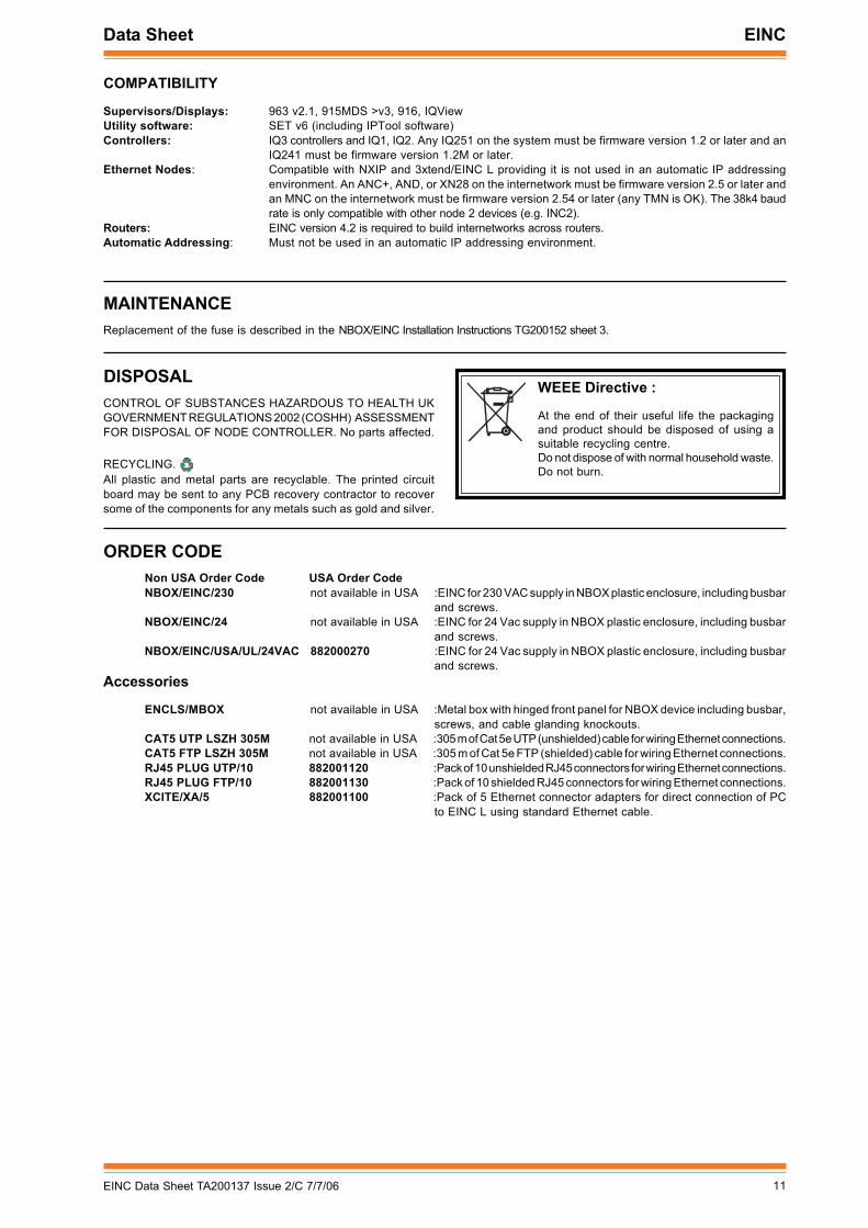
WEEE Directive :
At the end of their useful life the packagingand product should be disposed of using asuitable recycling centre.Do not dispose of with normal household waste.Do not burn.
EINC Data Sheet
12 EINC Data Sheet TA200137 Issue 2/C 7/7/06
Manufactured for and on behalf of the Environmental and Combustion Controls Division of Honeywell Technologies Sàrl, Ecublens, Route du Bois37,Switzerland by its Authorized Representative, Trend Control Systems Limited.
Trend Control Systems Limited reserves the right to revise this publication from time to time and make changes to the content hereofwithout obligation to notify any person of such revisions or changes.
Trend Control Systems LimitedP.O. Box 34, Horsham, West Sussex, RH12 2YF, UK. Tel:+44 (0)1403 211888 Fax:+44 (0)1403 241608 www.trend-controls.comTrend Control Systems USA6670 185th Avenue NE, Redmond, Washington 98052, USA. Tel: (425)869-8400, Fax: (425)869-8445 www.trend-controls.com
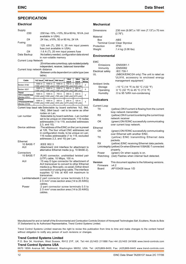
SPECIFICATIONElectrical
Supply/230 :230 Vac -15%, +10%, 50 or 60 Hz, 18 VA. (not
available in USA)./24 :24 Vac, ±10%, 50 or 60 Hz, 24 VA
Fusing/230 :125 mA (T), 250 V, 20 mm input powers
fuse.(not available in USA)./24 :1.6 A (T), 20 mm input powers fuse
Data Backup :No battery needed, configuration data storedin non-volatile memory
Current Loop Network:20 mA two wire current loop, opto-isolated polarityindependent, receiver, balanced transmitter
Current loop network distance:Between units dependent on cable type (seetable).
Mechanical
Dimensions :230 mm (9.06") x 181 mm (7.13") x 70 mm(2.76").
MaterialBox :ABSTerminal Cover:Clear Styrolux
Protection :IP30Weight :1.4 kg (3.08 lbs)
Environmental
EMCEmissions :EN50081-1Immunity :EN50082
Electrical safety :IEC 730-1UL :(NBOX/EINC/24 only) The unit is rated as
'UL916, accessory to enclosed energymanagement equipment.'
Ambient limitsStorage :-10 °C (14 °F) to 50 °C (122 °F)Operating :0 °C (32 °F) to 45 °C (113 °F)Humidity :0 to 95 %RH non-condensing
Indicators
Current LoopTX :(yellow) ON if current is flowing from the current
loop network transmitterRX :(yellow) ON if current is entering the current loop
network receiverOK :(green) ON if EINC successfully communicating
over current loop network.Ethernet
OK :(green) ON if EINC successfully communicatingover Ethernet with another EINC.
TX :(yellow) EINC transmitting Ethernet datapackets.
RX :(yellow) EINC receiving Ethernet data packets.Link integrity:(yellow) On when Ethernet 10 BASE-T connected
properly.Power :(green) On when supply is on.Watchdog :(red) Flashes when internal fault detected.
Version This document applies to the following versions.Firmware :v4.2Board :AP103428 issue 1/D
Current loop baud rate:Selectable by board switches 1k2, 9k6,19k2, 38k4 baud - set to be same as othernodes on Lan.
Lan number :Selectable by board switches - Lan numberset to be unique on internetwork; 116 nodesaddressable (1 to 119, excluded addresses2,3, and 10).
Device address :The address of the EINC on the Lan is presetat 126. The four virtual CNC addresses setin configuration mode, to be unique on Lan;116 nodes addressable (1 to 119, excludedaddresses 2,3, and 10) per Lan.
Ethernet10 BASE-T :IEEE 802.3AUI :Attachment Unit Interface for attachment to
alternative Ethernet media (e.g. 10 BASE-2).Connectors
10 BASE-T :RJ45 connector, unshielded twisted pair(UTP) cable, 10 Mbps, 100 m.
AUI :15 way D type connector for attachment ofAUI transceiver to convert to other Ethernetmedia (e.g. fibre optic, co-axial). Either directconnection or using drop cable. The interfacesupplies 12 Vdc at 400 mA maximum totransceiver.
Lan/internetwork:2 part connector screw terminals 0.5 to2.5 mm2 cross section area (14 to 20 AWG)cables.
Power :2 part connector screw terminals 0.5 to2.5 mm2 cross section area (14 to 20 AWG)cables.
Cable 1k2 baud 4k8 baud 9k6 baud19k2baud
38k4baud
No. ofWires
Belden 91821000 m
(1090 yds)1000 m
(1090 yds)1000 m
(1090 yds)700 m
(765 yds)500 m
(545 yds)2
Belden 92071000 m
(1090 yds)1000 m
(1090 yds)1000 m
(1090 yds)500 m
(545 yds)350 m
(380 yds)2
TrendTP/1/1/22/HF/500(Belden 8761)
1000 m(1090 yds)
1000 m(1090 yds)
700 m(765 yds)
350 m(380 yds)
250 m(270 yds)
2
TrendTP/2/2/22/HF/500(Belden 8723)
1000 m(1090 yds)
1000 m(1090 yds)
500 m(545 yds)
250 m(270 yds)
125 m(135 yds)
4