Embed Size (px)
Citation preview
87ENGINEERING GRAPHICS
All of you have seen a bicycle and most of you may know how to ride it. With the help of paddles
you may have driven it. It needs very little effort to run a bicycle. Do you know why a bicycle runs
so smoothly and easily? The reason is that friction is greatly reduced by using bearings in the
moving parts and you must have oiled/ greased these bearings from time to time.
In the industry also the bearings are used to help in smooth running of the shafts. As we all know
that the friction is a necessary evil. The friction generates heat and opposes the free movement
of the moving parts. We can not eliminate the friction together but we can reduce it to a large
extent by using some suitable lubricant.
The meaning of bearing as given in the Dictionary is a part of a machine which support another
part that turns round a wheel' or it can be defined as the support and guide for a rotating
,oscillating or sliding shaft, pivot or wheel' .
Bearings are used as a mechanical component to a certain part and this is done by utilizing the
small frictional force of the bearings, which makes them rotate easily, all the while with the force
and load acting against them.
There are two types of bearings according to the type of motion:
1. Plain bearings and 2. Anti-Friction bearings or Rolling Bearings
We will learn that plain bearings are such that they primarily support sliding, radial and
thrust loads and linear motions also.
1. Plain Journal Bearings: These support radial loads at right angles to the shaft axis.
2. Spherical Bearings: These are used where the loads are not aligned and are radial.
3. Thrust Bearings: These bearings support axial and radial loads.
4. Linear Bearings: These bearings only help in linear motion.
5. Pivot Bearings or Foot Step Bearings: These bearings are used where the thrust is only
axial.
CLASSIFICATION OF BEARINGS
Plain bearings may further be classified as:
CHAPTERCHAPTERCHAPTER 3BEARINGS
Downloaded from www.studiestoday.com
Downloaded from www.studiestoday.com
88 ENGINEERING GRAPHICS
ANTI-FRICTION OR ROLLER BEARINGS
These bearings can be:
1. Needle Bearings.
2. Ball Bearings and
3. Roller Bearings.
The bearings mentioned above can be rearranged according to the loading conditions as:
1. Journal Bearings: In this bearing the bearing pressure is perpendicular to the axis of the
shaft.
2. Thrust Bearing or Collar Bearing: In this bearing the pressure is parallel to the axis of the
shaft.
3. Pivot Bearing: In this bearing the bearing pressure is parallel to the axis of the shaft and
the end of the shaft, rests on the bearing surface.
4. Linear Bearings
5. Spherical Bearings.
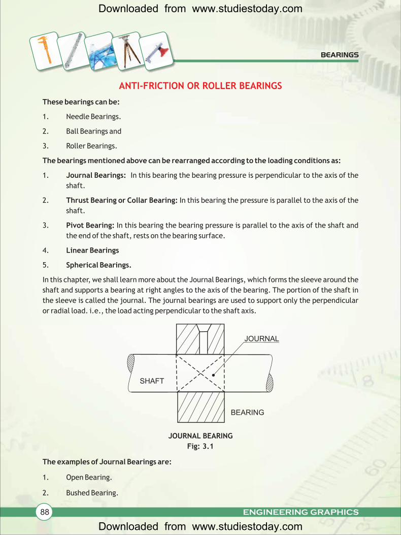
In this chapter, we shall learn more about the Journal Bearings, which forms the sleeve around the
shaft and supports a bearing at right angles to the axis of the bearing. The portion of the shaft in
the sleeve is called the journal. The journal bearings are used to support only the perpendicular
or radial load. i.e., the load acting perpendicular to the shaft axis.
JOURNAL BEARING
Fig: 3.1
The examples of Journal Bearings are:
1. Open Bearing.
2. Bushed Bearing.
BEARINGS
SHAFT
JOURNAL
BEARING
Downloaded from www.studiestoday.com
Downloaded from www.studiestoday.com
89ENGINEERING GRAPHICS
3. Plummer Block or Pedestal Bearing.
4. Pivot Bearing or Foot Step Bearing.
In our syllabus the Assembly and Dis-assembly of the following Bearings are prescribed, so let us
learn more about these in detail:
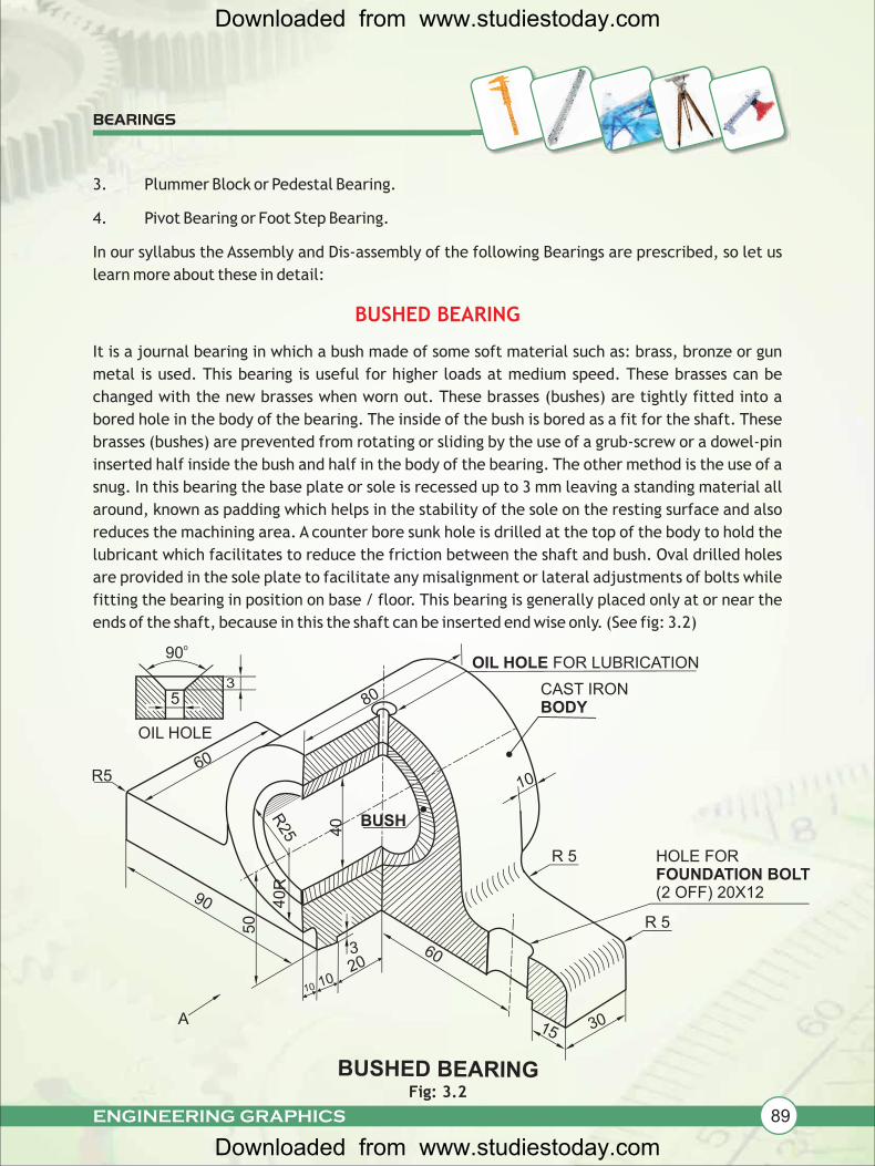
It is a journal bearing in which a bush made of some soft material such as: brass, bronze or gun
metal is used. This bearing is useful for higher loads at medium speed. These brasses can be
changed with the new brasses when worn out. These brasses (bushes) are tightly fitted into a
bored hole in the body of the bearing. The inside of the bush is bored as a fit for the shaft. These
brasses (bushes) are prevented from rotating or sliding by the use of a grub-screw or a dowel-pin
inserted half inside the bush and half in the body of the bearing. The other method is the use of a
snug. In this bearing the base plate or sole is recessed up to 3 mm leaving a standing material all
around, known as padding which helps in the stability of the sole on the resting surface and also
reduces the machining area. A counter bore sunk hole is drilled at the top of the body to hold the
lubricant which facilitates to reduce the friction between the shaft and bush. Oval drilled holes
are provided in the sole plate to facilitate any misalignment or lateral adjustments of bolts while
fitting the bearing in position on base / floor. This bearing is generally placed only at or near the
ends of the shaft, because in this the shaft can be inserted end wise only. (See fig: 3.2)
BUSHED BEARING
BEARINGS
Fig: 3.2
o90
53
OIL HOLE
90
50
1020
10
R560
80
OIL HOLE FOR LUBRICATION
CAST IRONBODY
10
R 5
HOLE FOR FOUNDATION BOLT (2 OFF) 20X12
R25 4
0 BUSH
40R
3 60
A
BUSHED BEARING
15 30
R 5
Downloaded from www.studiestoday.com
Downloaded from www.studiestoday.com
90 ENGINEERING GRAPHICS
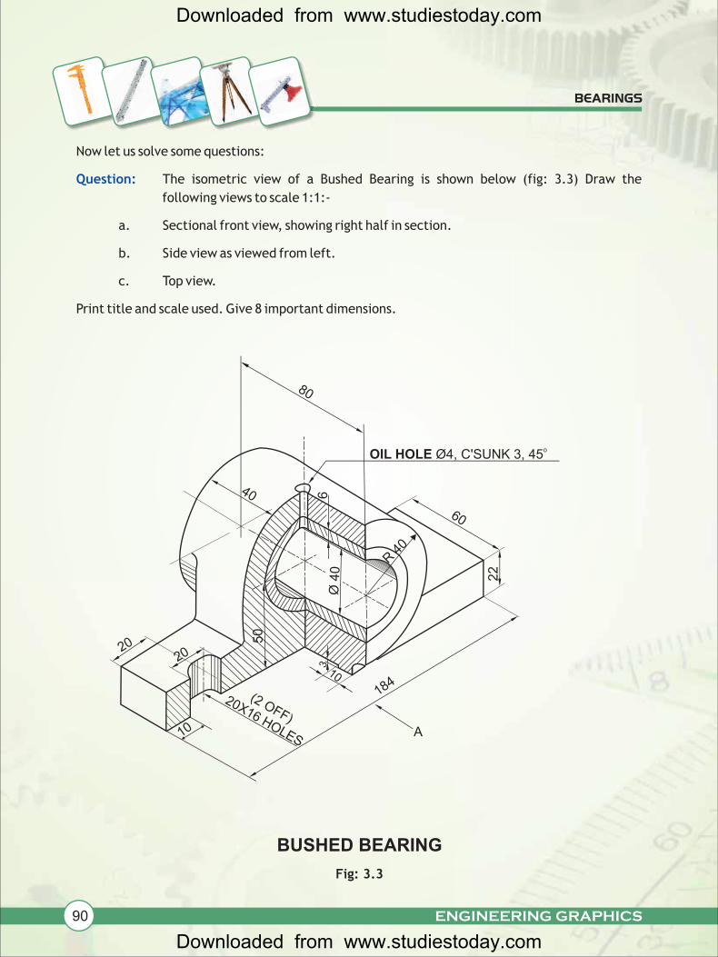
Now let us solve some questions:
The isometric view of a Bushed Bearing is shown below (fig: 3.3) Draw the
following views to scale 1:1:-
a. Sectional front view, showing right half in section.
b. Side view as viewed from left.
c. Top view.
Print title and scale used. Give 8 important dimensions.
Question:
BEARINGS
Fig: 3.3
40
Ø 4
06
R 4
0
50
2020
10
10
(2 OFF)
20X16 HOLES
BUSHED BEARING
80
60
22
184
A
oOIL HOLE Ø4, C'SUNK 3, 45
3
Downloaded from www.studiestoday.com
Downloaded from www.studiestoday.com
91ENGINEERING GRAPHICS
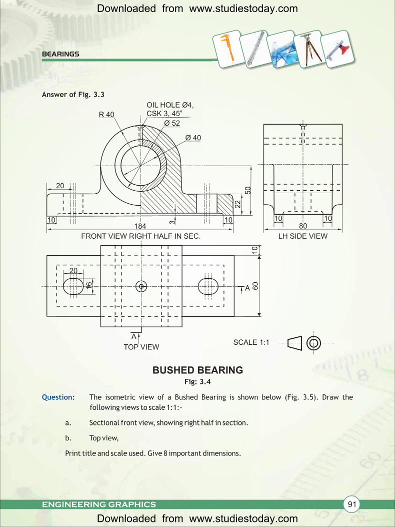
Question: The isometric view of a Bushed Bearing is shown below (Fig. 3.5). Draw the
following views to scale 1:1:-
a. Sectional front view, showing right half in section.
b. Top view,
Print title and scale used. Give 8 important dimensions.
BEARINGS
Fig: 3.4
10 1080
LH SIDE VIEW22
50
10
OIL HOLE Ø4, oCSK 3, 45
Ø 52
Ø 40
20
10184
3
R 40
FRONT VIEW RIGHT HALF IN SEC.
A
60
A
10
16
20
TOP VIEW
BUSHED BEARING
SCALE 1:1
Answer of Fig. 3.3
Downloaded from www.studiestoday.com
Downloaded from www.studiestoday.com
92 ENGINEERING GRAPHICS
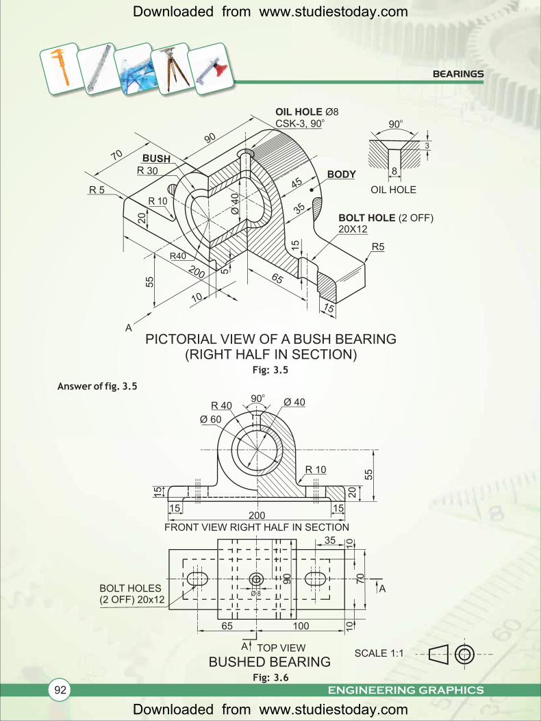
Fig: 3.5
Answer of fig. 3.5
BEARINGS
Fig: 3.6
200
55
20
90
OIL HOLE Ø8oCSK-3, 90
65
15
A
15
BOLT HOLE (2 OFF)20X12
70 BUSHR 30
45
35Ø 4
0
10
o90
8
OIL HOLE
R5
20
15
R 10
R 40o90
55
15200
15
Ø 60
Ø 40
TOP VIEW
100
06
Ø 8BOLT HOLES (2 OFF) 20x12
65
35
70
A
A
BUSHED BEARING
FRONT VIEW RIGHT HALF IN SECTION
R 5
10
10
BODY
PICTORIAL VIEW OF A BUSH BEARING (RIGHT HALF IN SECTION)
SCALE 1:1
R 10
R40
5
3
Downloaded from www.studiestoday.com
Downloaded from www.studiestoday.com
93ENGINEERING GRAPHICS
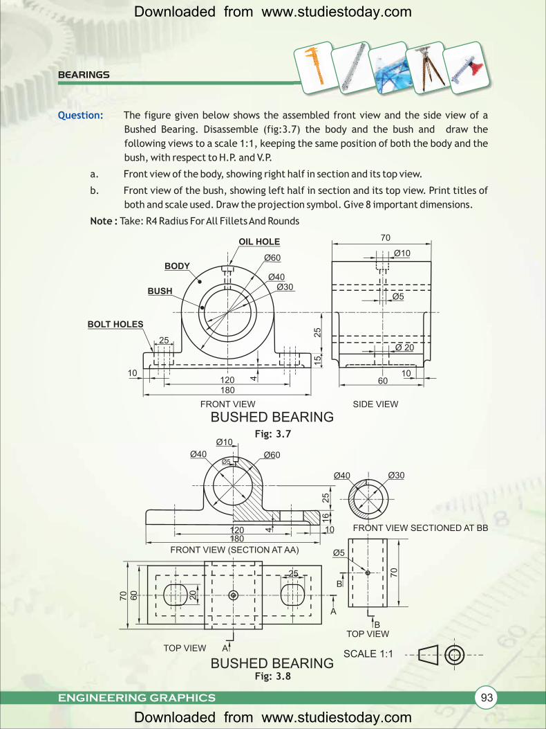
Question: The figure given below shows the assembled front view and the side view of a
Bushed Bearing. Disassemble (fig:3.7) the body and the bush and draw the
following views to a scale 1:1, keeping the same position of both the body and the
bush, with respect to H.P. and V.P.
a. Front view of the body, showing right half in section and its top view.
b. Front view of the bush, showing left half in section and its top view. Print titles of
both and scale used. Draw the projection symbol. Give 8 important dimensions.
Note : Take: R4 Radius For All Fillets And Rounds
Fig: 3.7
Fig: 3.8
BEARINGS
10
4120180
25
15
Ø40Ø30BUSH
BODYØ60
BUSHED BEARINGFRONT VIEW
Ø5
1060
SIDE VIEW
Ø 20
Ø10
70
25
Ø40
Ø10
Ø5Ø60
Ø40
25
Ø30
16
FRONT VIEW SECTIONED AT BB
Ø5
70
B
120180
4 10
FRONT VIEW (SECTION AT AA)
OIL HOLE
BOLT HOLES
SCALE 1:1
A
25
60
70 20
ATOP VIEW
BTOP VIEW
BUSHED BEARING
Downloaded from www.studiestoday.com
Downloaded from www.studiestoday.com
94 ENGINEERING GRAPHICS
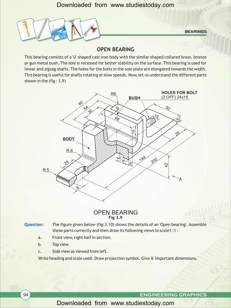
OPEN BEARING
This bearing consists of a 'U' shaped cast iron body with the similar shaped collared brass, bronze
or gun metal bush. The sole is recessed for better stability on the surface. This bearing is used for
linear and zigzag shafts. The holes for the bolts in the sole plate are elongated towards the width.
This bearing is useful for shafts rotating at slow speeds. Now, let us understand the different parts
shown in the (fig : 3.9)
Fig 3.9
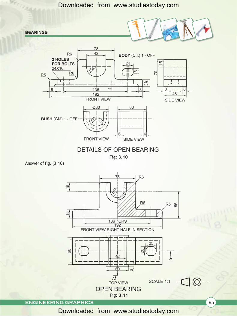
The figure given below (fig:3.10) shows the details of an 'Open bearing'. Assemble
these parts correctly and then draw its following views to scale1 :1 :
a. Front view, right half in section.
b. Top view.
c. Side view as viewed from left.
Write heading and scale used. Draw projection symbol. Give '6' important dimensions.
Question:
BEARINGS
OPEN BEARING
24
R 5
R 8
BODY
80
54
30
R6BUSH
HOLES FOR BOLT (2 OFF) 24x15
50
1568
15
6
6
2001444 8
42
28
15
A
8
9
Downloaded from www.studiestoday.com
Downloaded from www.studiestoday.com
95ENGINEERING GRAPHICS
Answer of fig. (3.10)
BEARINGS
Fig: 3.10
Fig: 3.11
7842
R21
24
16
R6
2 HOLES FOR BOLTS24X16
R6R5
FRONT VIEW SIDE VIEW
6
BUSH (GM) 1 - OFF
DETAILS OF OPEN BEARING
FRONT VIEW
Ø60 60
192136 4
15
70
15
8 8
SIDE VIEW
48
R15R21
BODY (C.I.) 1 - OFF
8
TOP VIEWA
6
42
20
60
25
A
60
FRONT VIEW RIGHT HALF IN SECTION
136192
CRS
15
15
78 R6
R6
R15
R5
OPEN BEARING
8
6
SCALE 1:1
55
Downloaded from www.studiestoday.com
Downloaded from www.studiestoday.com
96 ENGINEERING GRAPHICS
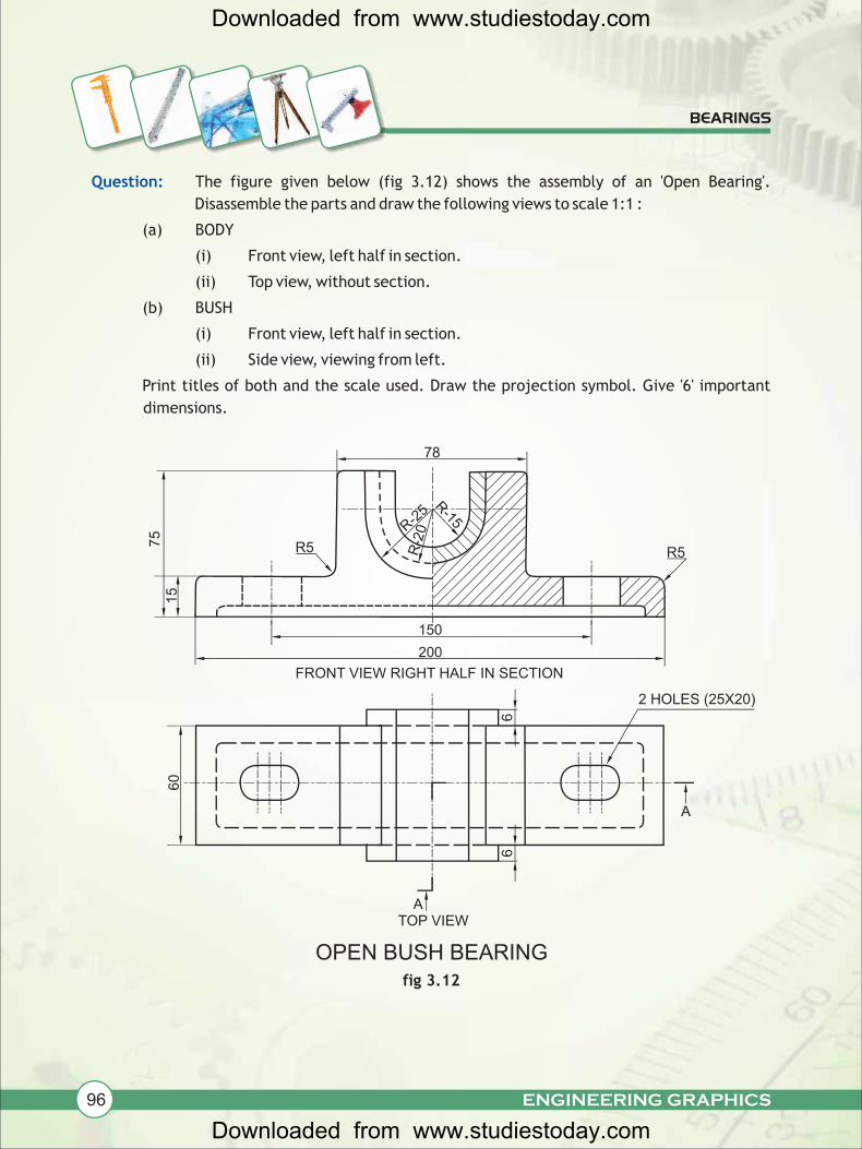
Question: The figure given below (fig 3.12) shows the assembly of an 'Open Bearing'.
Disassemble the parts and draw the following views to scale 1:1 :
(a) BODY
(i) Front view, left half in section.
(ii) Top view, without section.
(b) BUSH
(i) Front view, left half in section.
(ii) Side view, viewing from left.
Print titles of both and the scale used. Draw the projection symbol. Give '6' important
dimensions.
BEARINGS
fig 3.12
R-25
R-15
R5
150
78
200
75
15
FRONT VIEW RIGHT HALF IN SECTION
TOP VIEW
OPEN BUSH BEARING
6
60
R5
6
2 HOLES (25X20)
R-2
0
A
A
Downloaded from www.studiestoday.com
Downloaded from www.studiestoday.com
97ENGINEERING GRAPHICS
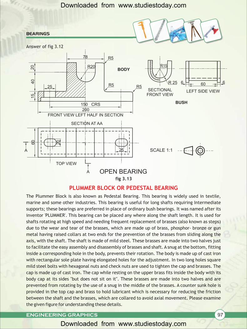
PLUMMER BLOCK OR PEDESTAL BEARING
The Plummer Block is also known as Pedestal Bearing. This bearing is widely used in textile,
marine and some other industries. This bearing is useful for long shafts requiring Intermediate
supports; these bearings are preferred in place of ordinary bush bearings. It was named after its
inventor 'PLUMMER'. This bearing can be placed any where along the shaft length. It is used for
shafts rotating at high speed and needing frequent replacement of brasses (also known as steps)
due to the wear and tear of the brasses, which are made up of brass, phosphor- bronze or gun
metal having raised collars at two ends for the prevention of the brasses from sliding along the
axis, with the shaft. The shaft is made of mild steel. These brasses are made into two halves just
to facilitate the easy assembly and disassembly of brasses and shaft. A snug at the bottom, fitting
inside a corresponding hole in the body, prevents their rotation. The body is made up of cast iron
with rectangular sole plate having elongated holes for the adjustment. In two long holes square
mild steel bolts with hexagonal nuts and check nuts are used to tighten the cap and brasses. The
cap is made up of cast iron. The cap while resting on the upper brass fits inside the body with its
body cap at its sides "but does not sit on it". These brasses are made into two halves and are
prevented from rotating by the use of a snug in the middle of the brasses. A counter sunk hole is
provided in the top cap and brass to hold lubricant which is necessary for reducing the friction
between the shaft and the brasses, which are collared to avoid axial movement. Please examine
the given figure for understanding these details.
BEARINGS
fig 3.13
LEFT SIDE VIEW
606 6R 25
SECTIONAL FRONT VIEW
BODY
R5
R5 R5
R20
78
20
40
15
25
150
200
CRS
FRONT VIEW LEFT HALF IN SECTION
SECTION AT AA
60
20
A
A
TOP VIEW
BUSH
OPEN BEARING
R15
SCALE 1:1
Answer of fig 3.12
25
Downloaded from www.studiestoday.com
Downloaded from www.studiestoday.com
98 ENGINEERING GRAPHICS
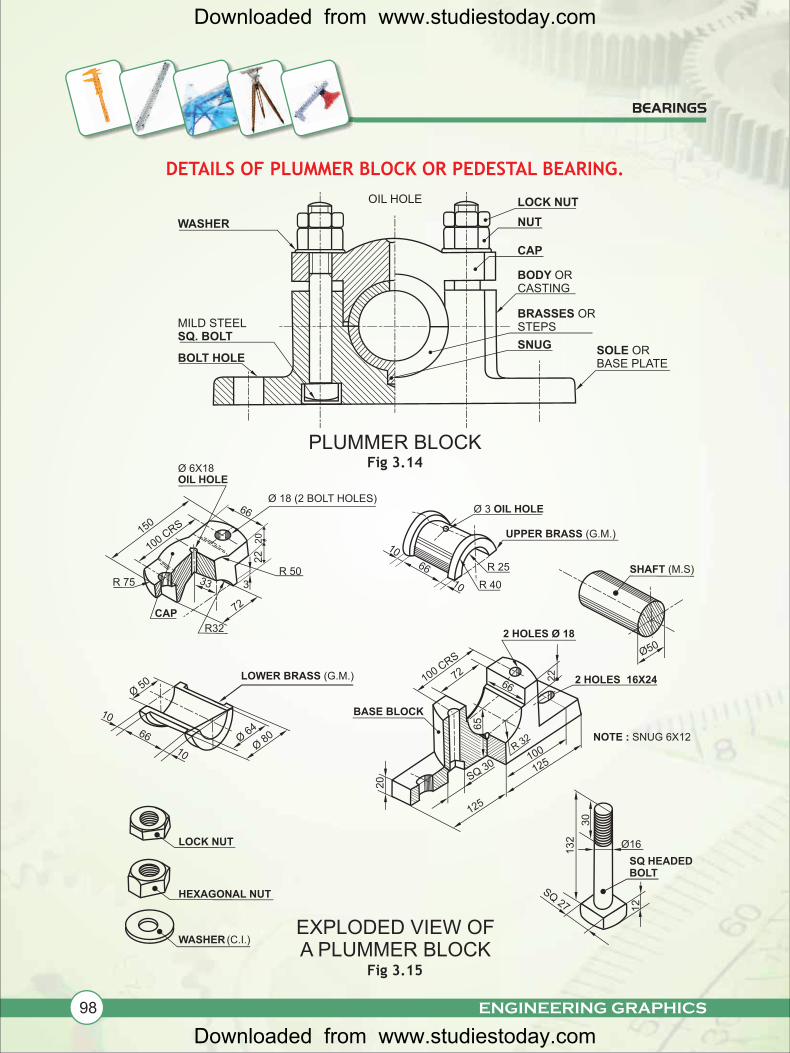
DETAILS OF PLUMMER BLOCK OR PEDESTAL BEARING.
Fig 3.14
Fig 3.15
BEARINGS
OIL HOLE LOCK NUT
NUT
CAP
BODY ORCASTING
BRASSES OR STEPS
SOLE OR BASE PLATE
PLUMMER BLOCK
WASHER
SNUG
MILD STEELSQ. BOLT
BOLT HOLE
SQ 27 12
SQ HEADED BOLT
R 40
Ø 3 OIL HOLE
UPPER BRASS (G.M.)
R 2566
10
10
LOCK NUT
HEXAGONAL NUT
WASHER (C.I.)
BASE BLOCK
Ø50
SHAFT (M.S)132 Ø16
LOWER BRASS (G.M.)
10
66
10
Ø 50
Ø 64
Ø 80
20
125
SQ 30
100 CRS
100R 32
125
22
65
6672
2 HOLES Ø 18
EXPLODED VIEW OF A PLUMMER BLOCK
R 75
R32
33
150
CAP
Ø 6X18OIL HOLE
100 CRS
66
20
22
3
72
R 50
Ø 18 (2 BOLT HOLES)
30
2 HOLES 16X24
NOTE : SNUG 6X12
Downloaded from www.studiestoday.com
Downloaded from www.studiestoday.com
99ENGINEERING GRAPHICS
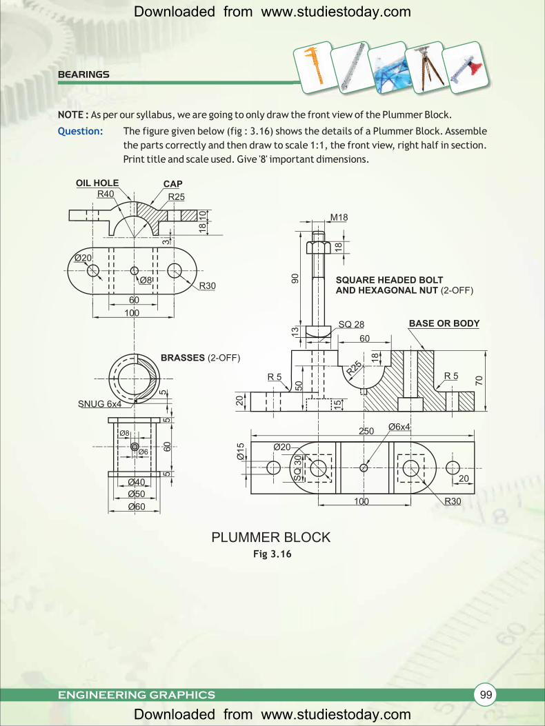
NOTE : As per our syllabus, we are going to only draw the front view of the Plummer Block.
The figure given below (fig : 3.16) shows the details of a Plummer Block. Assemble
the parts correctly and then draw to scale 1:1, the front view, right half in section.
Print title and scale used. Give '8' important dimensions.
Fig 3.16
Question:
BEARINGS
Ø20
Ø8
18
3
R2510
R40CAP
R30
60
100
Ø8
60
Ø6
Ø40
Ø50
Ø60
5
BRASSES (2-OFF)
PLUMMER BLOCK
M18
SQUARE HEADED BOLT AND HEXAGONAL NUT (2-OFF)
90
13
SQ 28
60
BASE OR BODY
R25
18
R 5
20
50
15
250
Ø15
SQ
30
Ø6x4
R30
20
100
Ø20
18
OIL HOLE
55
R 5
70
SNUG 6x4
Downloaded from www.studiestoday.com
Downloaded from www.studiestoday.com
100 ENGINEERING GRAPHICS
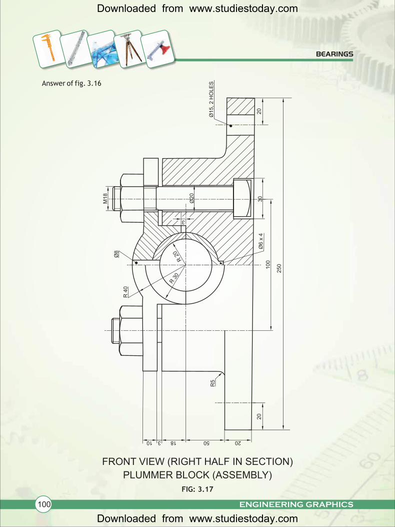
Answer of fig. 3.16
FRONT VIEW (RIGHT HALF IN SECTION)
PLUMMER BLOCK (ASSEMBLY)
FIG: 3.17
BEARINGS
R 3
0R
20
3
Ø20
R 4
0
Ø8
M18
Ø15, 2 H
OLE
S
20
20
100
250
Ø6 x
430
10 3 18 50 20
R5
Downloaded from www.studiestoday.com
Downloaded from www.studiestoday.com
101ENGINEERING GRAPHICS
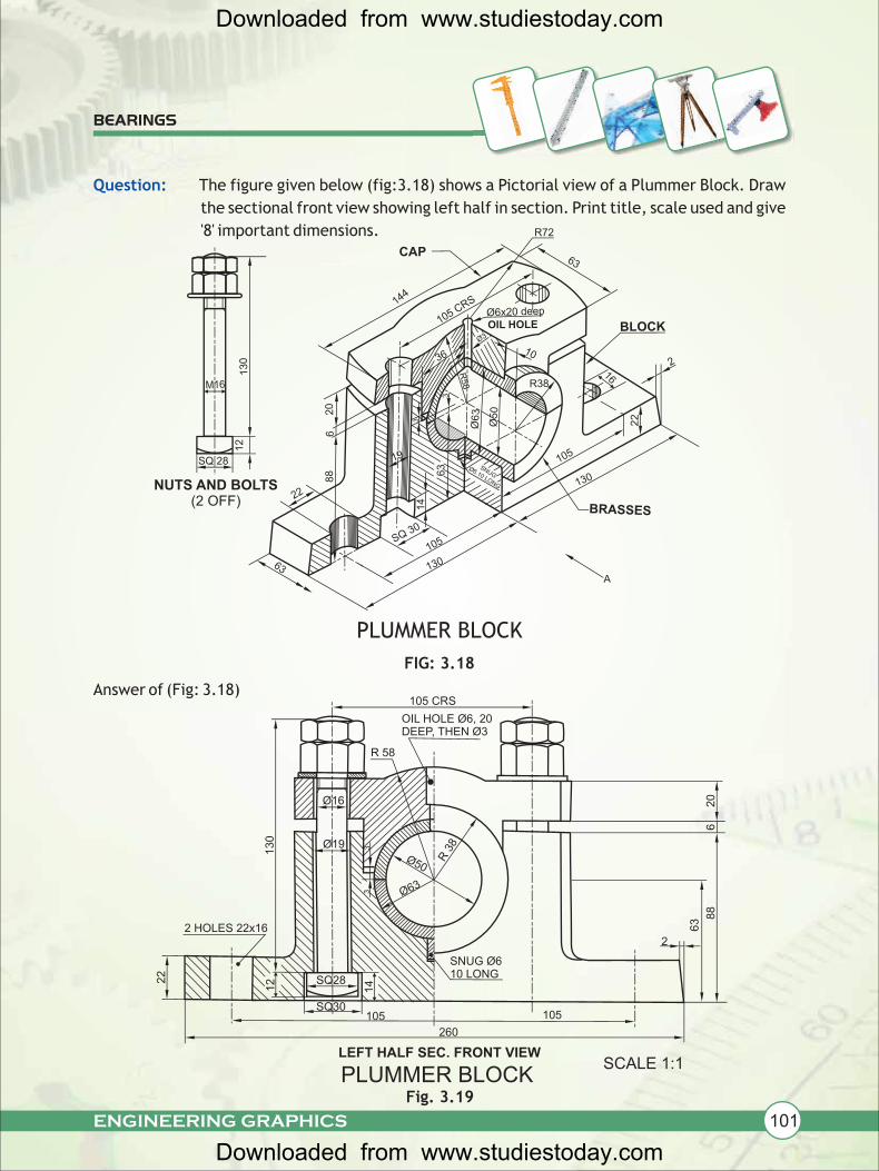
Question: The figure given below (fig:3.18) shows a Pictorial view of a Plummer Block. Draw
the sectional front view showing left half in section. Print title, scale used and give
'8' important dimensions.
PLUMMER BLOCK
FIG: 3.18
Answer of (Fig: 3.18)
BEARINGS
105 CRS
OIL HOLE Ø6, 20DEEP, THEN Ø3
R 58
20
68
8
63
2
Ø50
R 3
8
Ø63
Ø16
Ø19 33
13
0
2 HOLES 22x16
22
SQ28
12
SQ30105
14
105
260
SNUG Ø610 LONG
LEFT HALF SEC. FRONT VIEW
PLUMMER BLOCKFig. 3.19
144
CAP63
R72
105 CRS
Ø6x20 deep
OIL HOLE BLOCK
2
16
10
Ø3
Ø50
R58
3
19
63
14
105SQ 30
22
88
12
130
20
M16
SQ 28
NUTS AND BOLTS (2 OFF)
6
105
130
22
SNUGØ6.10 LONG
63
R38
BRASSES
A
Ø63
SCALE 1:1
36
130
3
Downloaded from www.studiestoday.com
Downloaded from www.studiestoday.com
102 ENGINEERING GRAPHICS
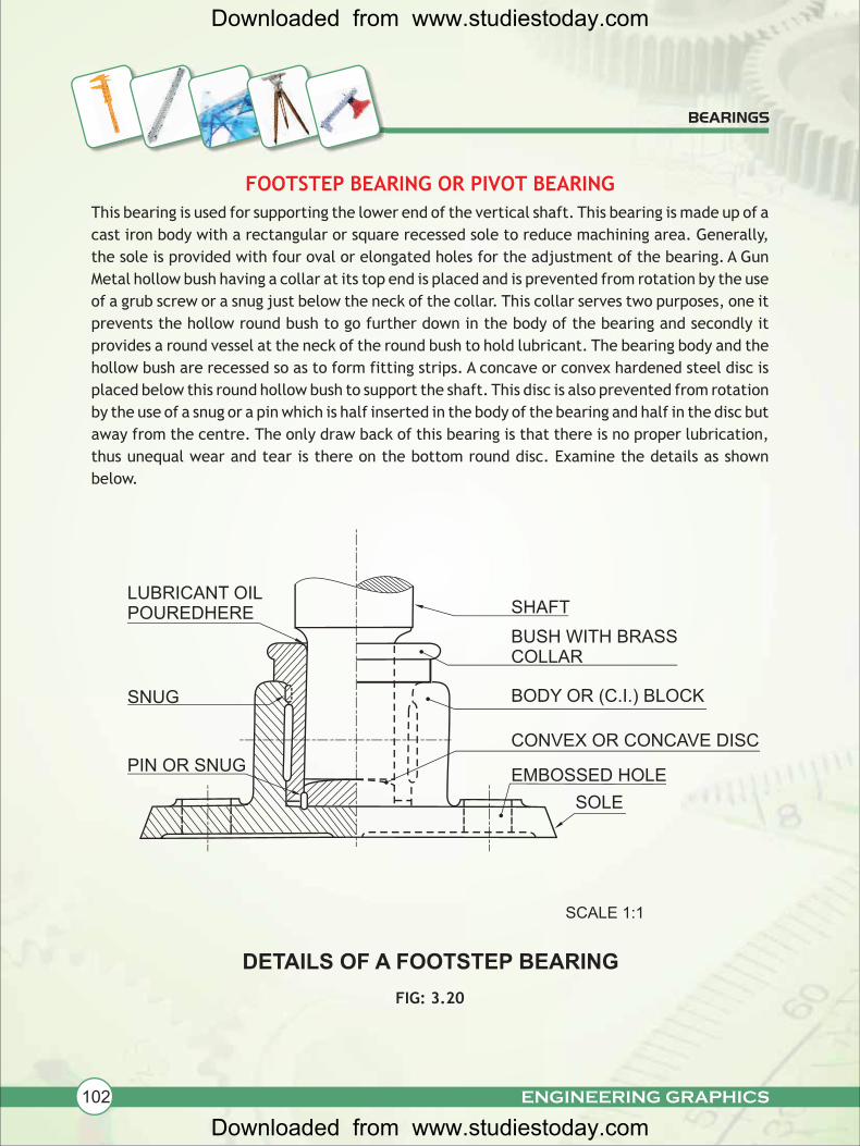
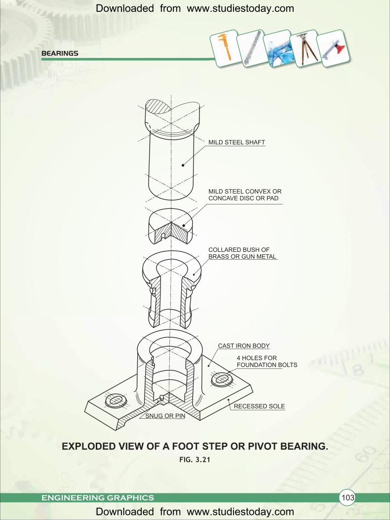
FOOTSTEP BEARING OR PIVOT BEARING
This bearing is used for supporting the lower end of the vertical shaft. This bearing is made up of a
cast iron body with a rectangular or square recessed sole to reduce machining area. Generally,
the sole is provided with four oval or elongated holes for the adjustment of the bearing. A Gun
Metal hollow bush having a collar at its top end is placed and is prevented from rotation by the use
of a grub screw or a snug just below the neck of the collar. This collar serves two purposes, one it
prevents the hollow round bush to go further down in the body of the bearing and secondly it
provides a round vessel at the neck of the round bush to hold lubricant. The bearing body and the
hollow bush are recessed so as to form fitting strips. A concave or convex hardened steel disc is
placed below this round hollow bush to support the shaft. This disc is also prevented from rotation
by the use of a snug or a pin which is half inserted in the body of the bearing and half in the disc but
away from the centre. The only draw back of this bearing is that there is no proper lubrication,
thus unequal wear and tear is there on the bottom round disc. Examine the details as shown
below.
FIG: 3.20
BEARINGS
LUBRICANT OIL POUREDHERE SHAFT
BUSH WITH BRASSCOLLAR
BODY OR (C.I.) BLOCK
CONVEX OR CONCAVE DISC
EMBOSSED HOLE
SOLE
SNUG
PIN OR SNUG
DETAILS OF A FOOTSTEP BEARING
SCALE 1:1
Downloaded from www.studiestoday.com
Downloaded from www.studiestoday.com
103ENGINEERING GRAPHICS
EXPLODED VIEW OF A FOOT STEP OR PIVOT BEARING.
FIG. 3.21
BEARINGS
COLLARED BUSH OF BRASS OR GUN METAL
CAST IRON BODY
4 HOLES FOR FOUNDATION BOLTS
RECESSED SOLE
SNUG OR PIN
MILD STEEL SHAFT
MILD STEEL CONVEX OR CONCAVE DISC OR PAD
Downloaded from www.studiestoday.com
Downloaded from www.studiestoday.com
104 ENGINEERING GRAPHICS
BEARINGS
20
Ø30
Ø94
14
Ø68
62
30
Ø15
Ø64 15
Ø5
7070
100 100
15
62
4
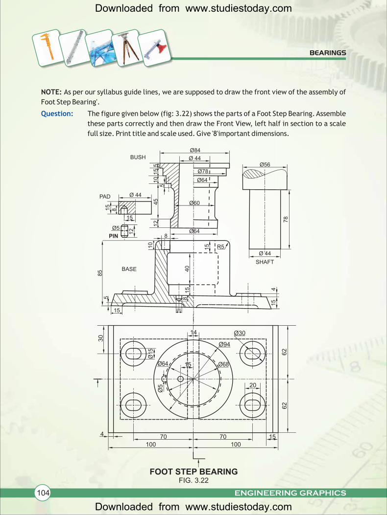
NOTE: As per our syllabus guide lines, we are supposed to draw the front view of the assembly of
Foot Step Bearing'.
The figure given below (fig: 3.22) shows the parts of a Foot Step Bearing. Assemble
these parts correctly and then draw the Front View, left half in section to a scale
full size. Print title and scale used. Give '8'important dimensions.
Question:5
15
FOOT STEP BEARING
Ø84
Ø 445 Ø56
BUSH1
0 1
5
Ø 44PAD
15
45
8
Ø5
15
12
5
Ø60
Ø64
Ø78
85 BASE 4
0
Ø5
15
1510
PIN
12
8Ø64
R5Ø 44
SHAFT
78
41
5
8
FIG. 3.22
Downloaded from www.studiestoday.com
Downloaded from www.studiestoday.com
105ENGINEERING GRAPHICS
BEARINGS
51
515
40
15
15
10
Ø44
15
70
20070
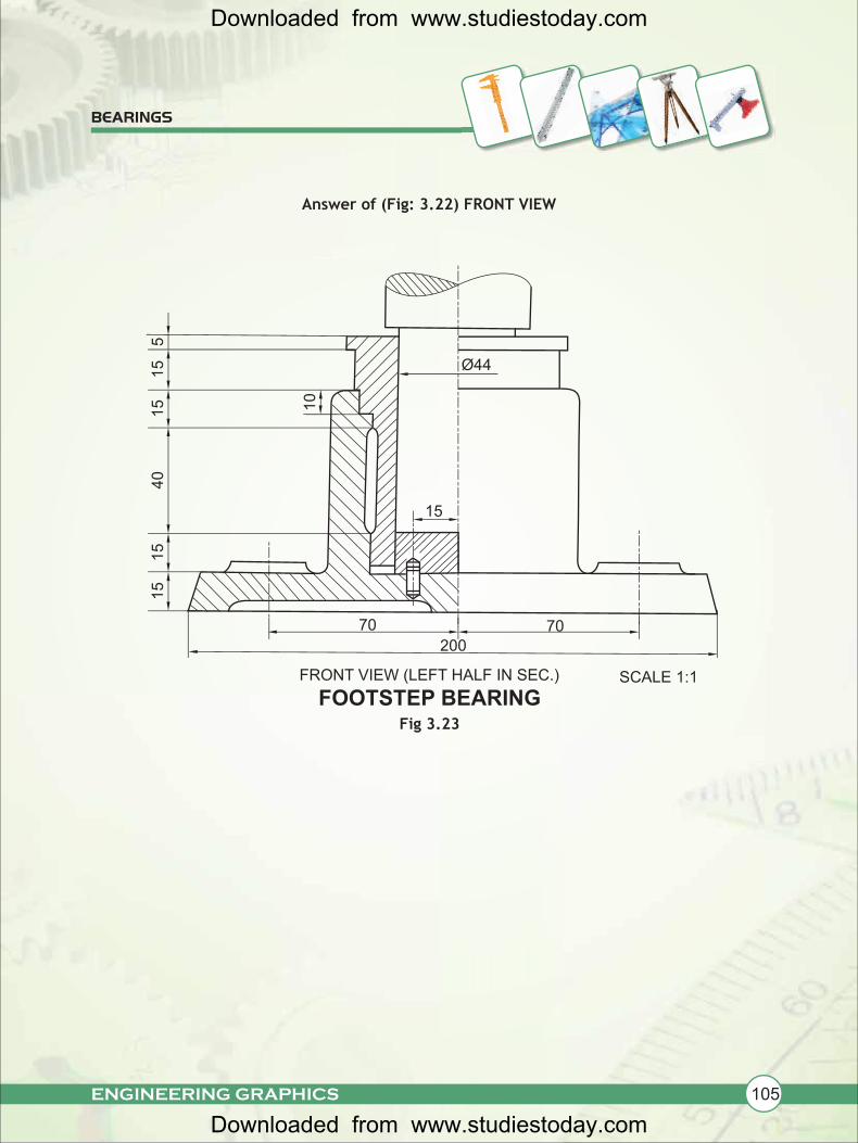
FRONT VIEW (LEFT HALF IN SEC.)
FOOTSTEP BEARING
Answer of (Fig: 3.22) FRONT VIEW
Fig 3.23
SCALE 1:1
Downloaded from www.studiestoday.com
Downloaded from www.studiestoday.com
106 ENGINEERING GRAPHICS
BEARINGS
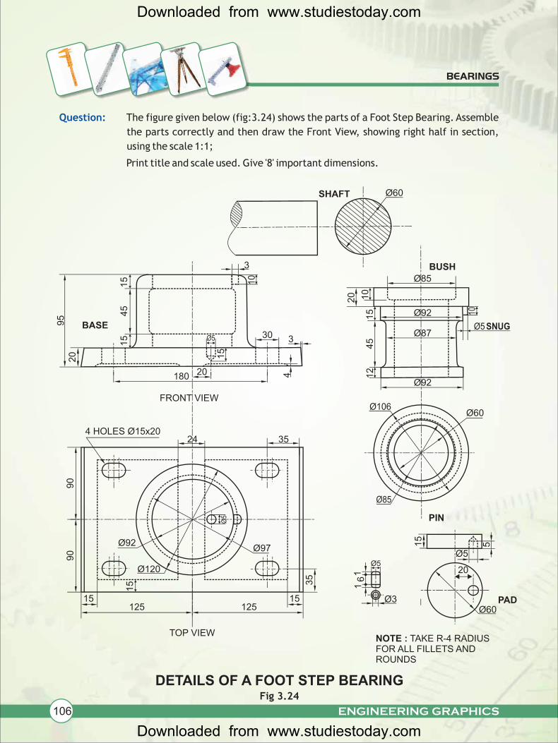
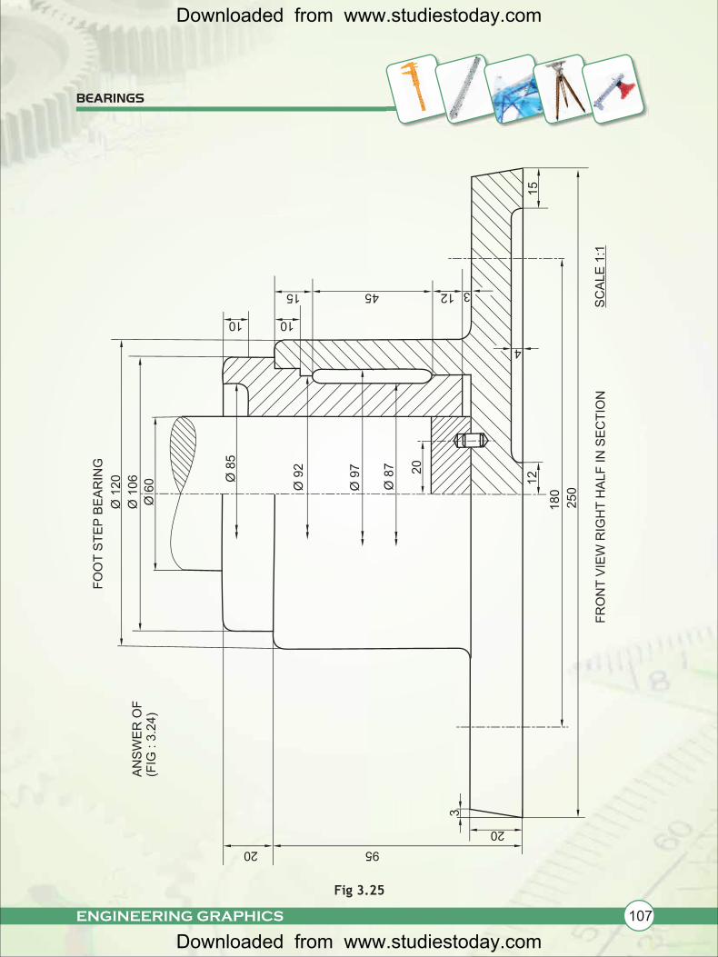
Question: The figure given below (fig:3.24) shows the parts of a Foot Step Bearing. Assemble
the parts correctly and then draw the Front View, showing right half in section,
using the scale 1:1;
Print title and scale used. Give '8' important dimensions.
DETAILS OF A FOOT STEP BEARING
Ø85BUSH
Ø92
10
20
15 10
Ø87SNUG
45
Ø60
Ø5
12
Ø92
Ø106Ø60
SHAFT
Ø60
15
5
Ø5
20Ø5
PADØ3
PIN
16
1
Ø85
35
12515
Ø97Ø92
35
Ø120
15
90
90
125
Ø5
NOTE : TAKE R-4 RADIUS FOR ALL FILLETS AND ROUNDS
24
20180
Ø5
20
15
15
4
30 3
95
BASE
45
15 10
3
Fig 3.24
TOP VIEW
FRONT VIEW
4 HOLES Ø15x20
15
Downloaded from www.studiestoday.com
Downloaded from www.studiestoday.com
107
BEARINGS
Fig 3.25
ENGINEERING GRAPHICS
Ø 8
5
Ø 9
2
Ø 9
7
Ø 8
7 20
12
180
250
4
312
15
45
10
15
Ø 1
20
Ø 1
06
Ø 6
0
FO
OT
ST
EP
BE
AR
ING
FR
ON
T V
IEW
RIG
HT
HA
LF
IN
SE
CT
ION
AN
SW
ER
OF
(F
IG : 3
.24)
SC
ALE
1:1
20
3
95
10
20
Downloaded from www.studiestoday.com
Downloaded from www.studiestoday.com


![Intial & Basic Configuration[1]](https://img.pdfslide.us/doc/110x75/55cf9c10550346d033a87095/intial-basic-configuration1.jpg)