Embed Size (px)
Citation preview

1
Installation and Parts Replacement Manual For
Dodge® TORQUE-ARM™ TXT Double Reduction
Taper Bushed and Straight BoreSpeed Reducers
TXT/HXT 1A TXT/HXT 2A TXT/HXT 3B TXT/HXT 4B
TXT/HXT 5C TXT/HXT 6A TXT/HXT 7A
TXT 8A TXT 9A TXT 10A
Includes Char-Lynn 6B Hydroil Reducers HXT 3B – 6B HXT 4B – 6B
HXT 5C – 6B HXT 6A – 6B
HXT 7A – 6B
WARNING: Because of the possible danger to person(s) or property from accidents which may result from the improper use of products, it is important that correct procedures be followed. Products must be used in accordance with the engineering information specified in the catalog. Proper installation, maintenance and operation procedures must be observed. The instructions in the instruction manuals must be followed. Inspections should be made as necessary to assure safe operation under prevailing conditions. Proper guards and other suitable safety devices or procedures, as may be desirable, or as may be specified in safety codes should be provided, and are neitherprovided by Rockwell Automation, nor are the responsibility of Rockwell Automation. This unit and its associated equipment must be installed, adjusted and maintained by qualified personnel who are familiar with the construction and operation of all equipment in the system and the potential hazards involved. When risks to persons or property may be involved, a holding device must be an integral part of the driven equipment beyond the speed reducer output shaft.
Rockwell Automation – Dodge/Reliance / P.O. Box 499 / 6040 Ponders Court / Greenville, SC 29602-0499 USA Tel: 864-297-4800 / Fax: 864-281-2433 / E-mail: [email protected]
© 2004 Rockwell Automation Dodge® and TORQUE-ARM™ are registered Trademarks of Rockwell Automation.
Printed in USA 09/04 499304
IM499304


2
CONTENTS
TORQUE-ARM REDUCER INSTALLATION………………..…... 3 TORQUE-ARM BUSHING INSTALLATION………...…………… 4 LUBRICATION………………………………………………………. 5 OIL VISCOSITY EQUIVALENCY CHART……………………….. 7 GUIDELINES FOR TORQUE-ARM REDUCER LONG-TERM STORAGE…………………………………………… 8 MOTOR MOUNTS………...………………………………………… 9 REPLACEMENT OF PARTS………………...…………………….. 10 REPLACEMENT PART AND KIT NUMBERS………...…………. 12 TXT1A & TXT2A REDUCER SECTION VIEW…………………… 14 TXT1A & TXT2A DETAILED PARTS LIST………………………. 15 TXT3B, TXT4B, & TXT5C REDUCER SECTION VIEW..………. 17 TXT3B, TXT4B & TXT5C DETAILED PARTS LIST…………….. 18 TXT6A thru TXT10A REDUCER SECTION VIEW……………… 21 TXT6A thru TXT10A DETAILED PARTS LIST………………….. 22 ACTUAL RATIOS……………………………………………………. 24

3
INSTALLATION 1. Use lifting bracket where applicable to lift reducer. 2. Determine the running positions of the reducer. (See Fig. 1) Note that the reducer is supplied with six plugs; four around the sides for horizontal installations and one on each face for vertical installations. These plugs must be arranged relative to the running positions as follows: Horizontal Installations - Install the magnetic drain plug in the hole closest to the bottom of the reducer. Install the filter/ventilation plug in topmost hole. Of the two remaining plugs on the sides of the reducer, the lowest plug is the minimum oil level plug. Vertical Installations - Install the filter/ventilation plug in the hole provided in the upper face of the reducer housing. If space is restricted on the upper face, install the vent in the highest hole on the side of the reducer per Figure 1 using the optional vertical vent kit. Install a plug in the hole in the bottom face of the reducer. Do not use this hole for the magnetic drain plug. Install the magnetic drain plug in the lowest hole on the sides of the reducer. Of the remaining holes on the sides of the reducer, use the plug in the upper housing half for the minimum oil level plug. Figure 1 – Mounting Positions
● Below 15 RPM output speed, oil level must be adjusted to reach the highest oil level plug. If reducer position is to vary from those shown in Figure 1, either more or less oil may be required. Consult Dodge. The running position of the reducer in a horizontal application is not limited to the four positions shown in Fig. 1. However, if running position is over 20° in position "B" & "D" or 5° in position "A" & "C", either way from sketches, the oil level plug cannot be used safely to check the oil level, unless during the checking, the torque arm is disconnected and the reducer is swung to within 20° for position "A" & "C" or 5° for position "B" & "D" of the positions shown in Fig. 1. Because of the many possible positions of the reducer, it may be necessary or desirable to make special adaptations using the lubrication filling holes furnished along with other standard pipe fittings, stand pipes and oil level gauges as required.
3. Mount reducer on driven shaft as follows: WARNING: To ensure that drive is not unexpectedly started, turn off and lock out or tag power source before proceeding. Remove all external loads from drive before removing or servicing drive or accessories. Failure to observe these precautions could result in bodily injury. For Taper Bushed Reducer: Mount the reducer on the driven shaft per instruction sheet No. 499629 packed with the tapered bushing kit. 4. Install sheave on input shaft as close to reducer as practical. (See Fig. 2) 5. If not using a Dodge Torque-Arm motor mount, install motor and V-belt drive so belt will approximately be at right angles to the centerline between driven and input shaft. (See Fig. 3) This will permit tightening the V-belt with the torque arm. 6. Install torque arm and adapter plates using the long reducer bolts. The adapter plates may be installed in any position around the input end of the reducer. 7. Install torque arm fulcrum on a flat and rigid support so that the torque arm will be approximately at right angles to the centerline through the driven shaft and the torque arm anchor screw. (See Fig. 4) Make sure that there is sufficient take-up in the turnbuckle for belt tension adjustment when using V-belt drive. CAUTION: Unit is shipped without oil. Add proper amount of recommended lubricant before operating. Failure to observe this precaution could result in damage to or destruction of the equipment 8. Fill gear reducer with the recommended volume of lubricant per table 2.
Figure 2 – Reducer and Sheave Installation
Figure 3 – Angle of V-Drive

4
Figure 4 – Angle of Torque-Arm TXT TAPERED BUSHING INSTALLATION WARNING: To ensure that drive is not unexpectedly started, turn off and lock out or tag power source before proceeding. Remove all external loads from drive before removing or servicing drive or accessories. Failure to observe these precautions could result in bodily injury. Taper Bore Bushings: 1. One bushing assembly is required to mount the reducer on the driven shaft. An assembly consists of two tapered bushings, bushing screws and washers, and necessary shaft keys or key. The driven shaft must extend through the full length of the reducer. The minimum shaft length, as measured from the end of the shaft to the outer edge of the bushing flange (see Figure 5), is given in Table 1. This dimension does not include dimension “A”. Dimension “A” should be added to the minimum shaft length to allow for the removal of the bushings at disassembly. 2. Place one bushing, flange end first, onto the driven shaft and position per dimension “A”, as shown in Table 1. This will allow the bolts to be threaded into the bushing and for future bushing and reducer removal. If the reducer must be positioned closer to the equipment than dimension “A”, place the screws, with washers installed, into the unthreaded holes of the bushing flange prior to placing the bushing on the shaft and position as required. 3. Insert the output key in the shaft and bushing. For easy of installation, rotate the driven shaft so that the shaft keyseat is at the top position. 4. Mount the reducer on the driven shaft and align the shaft key with the reducer hub keyway. Maintain the recommended minimum distance “A” from the shaft bearing. 5. Insert the screws, with washers installed, in the unthreaded holes in the bushing flange and align with the threaded holes in the bushing backup plate. If necessary, rotate the bushing backup plate to align with the bushing screws. Tighten the
screws lightly. If the reducer must be positioned closer than dimension “A”, place the screws with washers installed, in the unthreaded holes in the bushing before positioning reducer making sure to maintain at least 1/8” between the screw heads and the bearing. 6. Place the second tapered bushing in position on the shaft and align the bushing keyway with the shaft key. Align the unthreaded holes in the bushing with the threaded holes in the bushing backup plate. If necessary, rotate the bushing backup plate to align with the bushing holes. Insert bushing screws, with washers installed in the unthreaded holes in the bushing. Tighten screws lightly. 7. Alternately and evenly tighten the screws in the bushing nearest the equipment to the recommended torque given in Table 1. Repeat procedure on outer bushing. Figure 5 – Minimum Recommended Dimensions
AMINIMUM SHAFT LENGTH
Table 1 – Minimum Mounting Dimensions and Bolt Torques
Minimum Required Shaft Length Reducer Size Taper Bushing Straight Bushing
TXT1A 6-1/2 5-5/8 TXT2A 6-3/4 5-13/16 TXT3B 8-9/16 7-11/16 TXT4B 9-5/16 8-1/4 TXT5C 9-3/4 8-11/16 TXT6A 10-3/4 9-5/8 TXT7A 11-15/16 10-3/4 TXT8A 13-1/8 11-3/8 TXT9A 13-0 11-3/8
TXT10A 14-3/16 12-3/8
Bushing Screw Information and Minimum Clearance for Removal Reducer Size Fastener Size Torque in In.-Lbs. Dim. “A”
TXT1A 5/16-18 200 1-1/4 TXT2A 5/16-18 200 1-1/4 TXT3B 3/8-16 200 1-1/2 TXT4B 3/8-16 360 1-3/4 TXT5C 3/8-16 360 1-13/16 TXT6A 1/2-13 360 1-13/16 TXT7A 1/2-13 800 2-1/16 TXT8A 1/2-13 800 2-1/16 TXT9A 1/2-13 900 2-7/16 TXT10A 5/8-11 900 2-7/16

5
Straight Bore Bushings: 1. One bushing assembly is required to mount the reducer on the driven shaft. An assembly consists of one keyed straight bushing, one plain straight bushing, required set screws, and necessary shaft key or keys. The driven shaft must extent through the reducer to operate properly. The minimum shaft length, as measured from the end of the shaft to the outer edge of the retaining collar, is given in Table 1. 2. Install the plain bushing into the reducer output hub on the side toward the equipment or bearing. Remove two short set screws from the retaining collar and install two of the longer set screws supplied with the bushing kit. Line up the bushing holes with the set screws. Thread the set screws in until they locate into the bushing holes. Make sure the set screws are threaded in only enough to locate the bushing in the reducer hub and does not extend thru the bushing. 3. Install the keyed bushing into the opposite end of the reducer hub as the plain bushing. Remove one short set screw from the retaining collar and install the remaining set screw from the bushing kit into the collar. Line up the bushing hole with the set screw. Thread the set screw in until it locates into the bushing hole. Make sure the set screw is threaded in only enough to locate the bushing in the reducer hub and does not extend thru the bushing. 4. Mount the reducer on the driven shaft as close to the equipment or bearing as practical. 5. Line up the keyway in the bushing with the keyway in the driven shaft. Insert the key supplied with the bushing kit into the keyway. Gently tap the key into position until the key is flush with the edge of the reducer. Securely tighten all set screws. Standard Tapered Bushings Removal: 1. Remove bushing screws. 2. Place the screws in the threaded holes provided in the bushing flanges. Tighten the screws alternately and evenly until the bushings are free on the shaft. For ease of tightening screws make sure screw threads and threaded holes in the bushing flanges are clean. If the reducer was positioned closer than the recommended minimum distance “A” as shown in Table 1, loosen the inboard bushing screws until they are clear of the bushing flange by 1/8”. Locate two (2) wedges at 180 degrees between the bushing flange and the bushing backup plate. Drive the wedges alternately and evenly until the bushing is free on the shaft. 3. Remove the outside bushing, the reducer, key(s), and inboard bushing.
LUBRICATION IMPORTANT: Because Torque-Arm reducers are shipped without oil, it is extremely important to add the proper amount of lubricant prior to operating reducer. For most applications a high-grade petroleum-base rust and oxidation inhibited (R&O) gear oil is suitable. See Table 2 and Table 3 for proper oil volume and viscosity requirements. Under severe conditions EP oil can be used provided the reducer is not equipped with an internal backstop. Internal backstops are designed to rely on friction to operate correctly. EP lubricants contain friction modifiers that will alter backstop performance and therefore must not to be used on reducers equipped with internal backstops. Follow instructions on reducer warning tags. Lubrication is very important for satisfactory operation. The proper oil level must be maintained at all times. Frequent inspection, at least monthly, with the unit not running and allowing sufficient time for the oil to cool and the entrapped air to settle out of the oil should be made by removing the level plug and verifying the level is being maintained. If oil level is low, add the proper lubricant until the oil volume is increased to the correct level. After an initial operation of about two weeks, the oil should be changed. If desired, this oil may be filtered and reused. After the initial break in period, under average industrial operating conditions, the lubricant should be changed every 2500 hours of operation. At every oil change, drain reducer and flush with kerosene, clean magnetic drain plug and refill to proper level with new lubricant. Under extreme operating conditions, such as rapid rise and fall of temperature, dust, dirt, chemical particles, chemical fumes, or oil sump temperatures above 200°F, the oil should be changed every 1 to 3 months, depending on severity of conditions. CAUTION: Too much oil will cause overheating and too little will result in gear failure. Check oil level regularly. Failure to observe this precaution could result in equipment damage and/or bodily injury. Heating is a natural characteristic of enclosed gearing. A maximum gear case temperature approaching 200°F is not uncommon for some units operating in normal ambient temperatures of 80°F. When operating at the rated capacity with proper lubrication, no damage will result from this temperature. This maximum temperature was taken into consideration during the design of the reducer.

6
Table 2 – Oil Volumes
Approximate Volume of Oil to Fill Reducer to Oil Level Plug ■ ● ♦ Reducer † Position A † Position B † Position C † Position D † Position E † Position F
Size Ratio ▲Qt ♥L ▲Qt ♥L ▲Qt ♥L ▲Qt ♥L ▲Qt ♥L ▲Qt ♥L
TXT1A 9,15,25 1/2 1/2 1/2 1/2 5/8 5/8 3/4 3/4 1 1 1-1/4 1-1/8 TXT2A 9,15,25 7/8 7/8 1 1 5/8 5/8 1 1 1-5/8 1-1/2 1-3/4 1-5/8 TXT3B 9,15,25 1-1/2 1-3/8 1-1/2 1-3/8 3/4 3/4 2-1/4 2-1/8 2-5/8 2-1/2 3 2-7/8 TXT4B 9,15,25 1-7/8 1-3/4 2-1/4 2-1/8 1-1/4 1-1/8 1-3/4 1-5/8 3-3/8 3-1/8 4-1/4 4 TXT5C 9,15,25 3-1/4 3-1/8 4 3-3/4 3-1/4 3-1/8 4 3-3/4 7 6-5/8 8-5/8 8-1/8 TXT6A 9,15,25 4-1/4 4 5 4-3/4 4-1/4 4 5 4-3/4 8-5/8 8-1/8 9-1/8 8-5/8 TXT7A 9,15,25 6-1/2 6-1/8 8 7-1/2 7-1/4 6-7/8 9-1/4 8-3/4 15-3/8 14-1/2 16-3/8 15-1/2 TXT8A 15,25 8-1/2 8 11 10-3/8 10-1/2 9-7/8 8-1/2 8 19-1/8 18-1/8 19-1/8 18-1/8 TXT9A 15,26 13 12-1/4 13 12-1/4 12-1/2 11-7/8 14-1/4 13-1/2 25-3/8 24 25-3/8 24
TXT10A 15,24 23 21-3/4 14 13-1/4 15-3/4 14-7/8 18-3/4 17-3/4 41 38-3/4 41 38-3/4 ■ Oil quantity is approximate. Service with lubricant until oil runs out of oil level hole. † Refer to Figure 1 for mounting positions. ▲ US measure: 1 quart = 32 fluid ounces = .94646 liters. ♥ Conversion from quarts rounded values. ● Below 15 RPM output speed, oil level must be adjusted to reach the highest oil level plug. If reducer position is to vary from those shown in Figure 1, either more or less oil may be required. Consult Dodge. ♦ Consult Dodge for proper oil level for reducers equipped with backstops and which are mounted in either the C position or D position. Table 3 – Oil Recommendations
ISO Grades For Ambient Temperatures of 50˚F to 125˚F ■ Output RPM
Torque-Arm Reducer Size
TXT1A TXT2A TXT3B TXT4B TXT5C TXT6A TXT7A TXT8A TXT9A TXT10A 301 – 400 320 320 220 220 220 220 220 220 220 220 201 – 300 320 320 220 220 220 220 220 220 220 220 151 – 200 320 320 220 220 220 220 220 220 220 220 126 – 150 320 320 320 220 220 220 220 220 220 220 101 – 125 320 320 320 320 220 220 220 220 220 220 81 – 100 320 320 320 320 320 220 220 220 220 220 41 – 80 320 320 320 320 320 220 220 220 220 220 11 – 40 320 320 320 320 320 320 320 320 320 320 1 – 10 320 320 320 320 320 320 320 320 320 320
ISO Grades For Ambient Temperatures of 15˚F to 60˚F ■
Output RPM
Torque-Arm Reducer Size
TXT1A TXT2A TXT3B TXT4B TXT5C TXT6A TXT7A TXT8A TXT9A TXT10A 301 – 400 220 220 150 150 150 150 150 150 150 150 201 – 300 220 220 150 150 150 150 150 150 150 150 151 – 200 220 220 150 150 150 150 150 150 150 150 126 – 150 220 220 220 150 150 150 150 150 150 150 101 – 125 220 220 220 220 150 150 150 150 150 150 81 – 100 220 220 220 220 220 150 150 150 150 150 41 – 80 220 220 220 220 220 150 150 150 150 150 11 – 40 220 220 220 220 220 220 220 220 220 220 1 – 10 220 220 220 220 220 220 220 220 220 220
■ Notes: 1. Assumes auxiliary cooling where recommended in the catalog. 2. Pour point of lubricant selected should be at least 10°F lower than expected minimum ambient starting temperature. 3. Extreme pressure (EP) lubricants are not necessary for average operating conditions. TORQUE-ARM internal backstops are not suitable for use with EP lubricants. 4. Special lubricants may be required for food and drug industry applications where contact with the product being manufactured may occur. Consult a lubrication manufacturer’s representative for his recommendations. 5. For reducers operating in ambient temperatures between -22°F (-30°C) and 20°F (–6.6°C) use a synthetic hydrocarbon lubricant, 100 ISO grade or AGMA 3 grade (for example, Mobil SHC627). Above 125°F (51°C), consult DODGE Gear Application Engineering (864) 288-9050 for lubrication recommendation. 6. Mobil SHC630 Series oil is recommended for high ambient temperatures.

7
OIL VISCOSITY EQUIVALENCY CHART
2000
1000
800
600
500
400
300
200
100
80
60
5040
30
20
10
8
6
5
4
3
2
70
60
50
40
30
20
10
8
5
4
9
7
6
1500
1000
680
460
320
220
150
100
68
8A
8
7
6
5
4
3
2
85W
250
140
90
80W
46
32
22
15
10
7
5
175W
3
2
300
200
150
100
8070
60
50
40
35
32
400
500600
800
1000
1500
2000
3000
4000
50006000
800010,000
cSt/40°C 100°C
cSt/ ISOVG
AGMAGRADES
GRADESGEAR OILS
SUS/100°F
SUS/210°F
SAE
KINEMATICVISCOSITIES
SAYBOLTVISCOSITIES
200
300
100
90
80
70
60
55
50
45
40VISCOSITIES CAN BERELATED HORIZONTALLYONLY.VISCOSITIES BASED ON96 VI SINGLE GRADEOILS.ISO ARE SPECIFIED AT40°C.AGMA ARE SPECIFIED AT40°C.SAE 75W, 80W, AND 85WSPECIFIED AT LOWTEMPERATURE. EQUIVALENTVISCOSITIES FOR 100°FAND 200°F ARE SHOWN.SAE 90 TO 250 SPECIFIEDAT 100°C.

8
GUIDELINES FOR TXT REDUCER LONG-TERM STORAGE During periods of long storage, or when waiting for delivery or installation of other equipment, special care should be taken to protect a gear reducer to have it ready to be in the best condition when placed into service. By taking special precautions, problems such as seal leakage and reducer failure due to lack of lubrication, improper lubrication quantity, or contamination can be avoided. The following precautions will protect gear reducers during periods of extended storage: Preparation: 1. Drain oil from the unit. Add a vapor phase corrosion inhibiting oil (VCI-105 oil by Daubert Chemical Co.) in accordance with Table 4. 2. Seal the unit airtight. Replace the vent plug with a standard pipe plug and wire the vent to the unit. 3. Cover all unpainted exterior parts with a waxy rust preventative compound that will keep oxygen away from the bare metal. (Non-Rust X-110 by Daubert Chemical Co. or equivalent) 4. The instruction manuals and lubrication tags are paper and must be kept dry. Either remove these documents and store them inside, or cover the unit with a durable waterproof cover which can keep moisture away. 5. Protect reducer from dust, moisture, and other contaminants by storing the unit in a dry area. 6. In damp environments, the reducer should be packed inside a moisture-proof container or an envelope of polyethylene containing a desiccant material. If the reducer is to be stored outdoors, cover the entire exterior with a rust preventative. When placing the reducer into service: 1. Fill the unit to the proper oil level using a recommended lubricant. The VCI oil will not affect the new lubricant. 2. Clean the shaft extensions with petroleum solvents. 3. Assemble the vent plug into the proper hole. Follow the installation instructions provided in this manual.
Table 4 – Quantities of VCI #105 Oil
Reducer Size Quantity (Ounces / Milliliter) TXT1A 1 / 30 TXT2A 1 / 30 TXT3B 1 / 30 TXT4B 1 / 30 TXT5C 1 / 30 TXT6A 2 / 59 TXT7A 2 / 59 TXT8A 3 / 89 TXT9A 4 / 118
TXT10A 6 / 177 VCI #105 and #10 are interchangeable. VCI #105 is more readily available.

9
MOTOR MOUNTS Figure 6 – Motor Mount Components
Motor Mount Installation: The TA motor mount is designed to be installed on the output end of the reducer as shown in Figure 6. If bottom mounting is desired, use the optional TAB style. TA1M thru TA7M Motor Mount: Remove the required housing bolts on the output end of the reducer. Place the motor mount brackets in position and install the longer housing bolts supplied with the motor mount assembly. Do not fully tighten the housing bolts at this time. Install the bottom plate to the motor mount brackets and tighten with the hardware provided. Next, tighten the housing bolts to the torque values listed in Table 6. Install the four adjusting studs to the bottom plate using the jam nuts provided and securely tighten. These nuts will not require any further adjustment. Add one additional jam nut to each stud and thread approximately to the middle of the stud. Install the top motor plate on top of the jam nuts. Assemble the remaining jam nuts on studs to secure top motor plate. Do not fully tighten these nuts yet.
Mount motor, drive and driven sheaves, and v-belts. Note: Mount driven sheave as close to the reducer housing as practical. Adjust v-belts to the proper tension by adjusting the jam nuts and securely tighten. Check all bolts to insure that they are securely tightened. TA8 thru TA10 Motor Mount: Remove the required housing bolts on the output end of the reducer. Place the motor mount brackets in position and install the longer housing bolts supplied with the motor mount assembly. Do not fully tighten the housing bolts at this time. Install the four adjusting studs to the top plate as shown using the jam nuts provided and securely tighten. Add one additional jam nut to each stud and thread approximately to the middle of the stud. Install this assembly to the motor mount brackets and install the remaining jam nuts onto the studs to secure the top plate to the brackets. Tighten the housing bolts to the torque values listed in Table 6. Loosely install the front motor rail to the top plate. Measure the distance between the front and rear mounting holes on the motor and position the rear motor rail at this distance and loosely bolt to the top plate. Center the motor on the motor rails and securely bolt the motor to the motor rails. Install the motor sheave and reducer sheave on their shafts. Mount the reducer sheave as close to the housings as practical. Install the v-belts and adjust the motor rails to permit proper alignment of the v-belts to the sheaves. Securely tighten the motor rails to the mounting plate. Adjust the v-belts to the proper tension and securely tighten the adjusting nuts. Check all bolts to see that they are securely tightened. WARNING: To ensure that drive is not unexpectedly started, turn off and lock out or tag power source before proceeding. Remove all external loads from drive before removing or servicing drive or accessories. Failure to observe these precautions could result in bodily injury.

10
REPLACEMENT OF PARTS IMPORTANT: Using tools normally found in a maintenance department, a Dodge Torque-Arm speed reducer can be disassembled and reassembled by careful attention to the instructions following. Cleanliness is very important to prevent the introduction of dirt into the bearings and other parts of the reducer. A tank of clean solvent, an arbor press, and equipment for heating bearings and gears (for shrinking these parts on shafts) should be available. Our factory is prepared to repair reducers for customers who do not have proper facilities or who, for any reason, desire factory service. The oil seals are designed with a contact lip. Considerable care should be used during disassembly and reassembly to avoid damage to the surface on which the seals rub. The keyseat in the input shaft, as well as any sharp edges on the output hub should be covered with tape or paper before disassembly or reassembly. Also, be careful to remove any burrs or nicks on surfaces of the input shaft or output hub before disassembly or reassembly. Ordering Parts: When ordering parts for a Dodge Torque Arm reducer, specify reducer part number, part name, and quantity required. It is strongly recommended that, when a pinion or gear is replaced, the mating pinion or gear is replaced also. If the large gear on the output hub must be replaced, it is recommended that an output hub assembly consisting of a gear assembled on a hub be ordered to ensure undamaged surfaces on the output hub where the output seals rub. However, if it is desired to use the old output hub, press the gear and bearing off and examine the rubbing surface under the oil seal carefully for possible scratching or other damage resulting from the pressing operation. To prevent oil leakage at the shaft oil seals, the smooth surface of the output hub must not be damaged. If any parts must be pressed from a shaft or from the output hub, this should be done before ordering parts to make sure that none of the bearings or other parts are damaged in removal. Do not press against rollers or cage of any bearing. Because old shaft oil seals may be damaged in disassembly, it is advisable to order replacements for these parts. Removing Reducer from Shaft: WARNING: To ensure that drive is not unexpectedly started, turn off and lock out or tag power source before proceeding. Remove all external loads from drive before removing or servicing drive or accessories. Failure to observe these precautions could result in bodily injury.
Taper Bushed Reducer: 1. Disconnect and remove belt guard, v-drive, and motor mount as required. Disconnect torque arm rod from reducer adapter. 2. Remove bushing screws. 3. Place the screws in the threaded holes provided in the bushing flanges. Tighten the screws alternately and evenly until the bushings are free on the shaft. For ease of tightening screws, make sure screw threads and threaded holes in bushing flanges are clean. A tap can be used to clean out the threads. Use caution to use the proper size tap to prevent damage to the threads. 4. Remove the outside bushing, the reducer, and then the inboard bushing. Straight Bore Reducer: 1. Disconnect and remove belt guard, v-drive, and motor mount as required. Disconnect torque arm rod from reducer adapter. 2. Loosen and remove the set screws in both output hub collars. 3. Remove the collar from the output hub closest to the end of the shaft. This will expose three puller holes in the output hub to permit the use of a three prong puller. In removing the reducer from the shaft, use care not to damage the reducer output hub. Disassembly: 1. Drain all oil from the reducer. 2. Remove all locking collars, retaining rings, and bushing backup plated as required. Position the reducer on its side and remove all housing bolts. Using the three pry slots around the periphery of the flange, gently separate the housing halves and open evenly to prevent damage to the parts inside. Remove the two dowel pins. 3. Lift input shaft, all gear assemblies, and bearing assemblies from housing. 4. Remove seals from housing. 5. Remove bearings from shafts and hubs. Be careful not to scratch or damage any assembly or seal area during bearing removal. The hub assembly can be disassembled for gear replacement but if scratching or grooving occurs on the hub, seal leakage will occur and the hub will need to be replaced.

11
TXT Reassembly: 1. Output Hub Assembly: Heat gear to 325°F to 350°F to shrink onto hub. Heat bearings to 270°F to 290°F to shrink onto hub. Any damage to the hub surfaces where the oil seals rub will cause leakage, making it necessary to replace the hub. 2. Countershaft Assembly: Heat gear to 325°F to 350°F and bearings to 270°F to 290°F to shrink onto shaft. 3. Input Shaft Assembly: Heat bearings 270°F to 290°F to shrink onto shaft. Press bearings on shaft. 4. Drive the two dowel pins into place in the right-hand housing half (backstop side). 5. Place R.H. housing half on blocks to allow for protruding end of output hub. 6. Install all bearing cups on TXT3B thru TXT10A in right-hand housing half, making sure they are properly seated. TXT1A and TXT2A reducers use ball bearings on all shafts and do not incorporate bearing cups. 7. Mesh output hub gear and small countershaft gear together and set in place in housing. Set input shaft assembly in place in the housing. Make sure bearing rollers (cones) are properly seated in their cups. 8. Make sure both housing halves are clean. Apply a continuous 1/8” diameter bead of Dow Corning RTV732 sealant on the flange surface of the R.H. housing (make sure RTV is placed around all bolt holes). Set the left-hand housing half into position onto the dowel pins and gently tap with a soft hammer (rawhide, not lead hammer) until housing bolts can be used to draw housing halves together. Make sure reducer shafts do not bind while tightening housing bolts. Torque housing bolts per torque values listed in Table 6. 9. On TXT1A and TXT2A reducers, skip to step number 12. 10. Place the output bearing cup into the housing and tap into place. Install the output seal carrier and draw down with two bolts 180° apart to 50 inch pounds of torque. Loosen both bolts then retighten finger tight only. Measure the clearance between the housing and carrier flange at each bolt and average the two values. Add 0.010” to the average reading and make up shim pack. Install shim pack between the carrier flange and the reducer housing. Torque the bolts to the value shown in Table 6. Using a magnetic base and dial indicator, check the axial end play. Add or remove shims until the axial endplay reading of the output hub is per Table 5. 11. Repeat step 9 above for installing and adjusting the countershaft and input bearings. Adjust the axial endplay per Table 5.
12. Install input and output seals. Lightly coat the seal lips with Mobilith AW2 All-Purpose grease or equivalent. The possibility of damage and consequent oil leakage can be decreased by covering all sharp edges with tape prior to seal installation. Seals should be pressed or tapped with a soft hammer evenly into place in the reducer housing, applying pressure only on the outer edge of the seals. Extreme care should be used when installing seals to avoid damage due to contact with sharp edges on the input shaft or output hub. A slight oil leak at the seals may be evident during initial running, but should disappear unless seals have been damaged. 13. Install bushing backup plates and snap rings on Taper Bushed reducers or hub collars on straight bore reducers and install backstop cover. Make sure all bolts are tightened to the correct torque values listed in Table 6. Table 5 – Bearing Adjustment Tolerances
Bearing Endplay Values Reducer Size Input Countershaft Output TXT1A N/A N/A N/A TXT2A N/A N/A N/A TXT3B .002-.004 Loose .0005-.003 Loose .0005-.003 Loose TXT4B .002-.004 Loose .0005-.003 Loose .0005-.003 Loose TXT5C .002-.004 Loose .0005-.003 Loose .0005-.003 Loose TXT6A .002-.004 Loose .0005-.003 Loose .0005-.003 Loose TXT7A .002-.004 Loose .0005-.003 Loose .0005-.003 Loose TXT8A .002-.004 Loose .0005-.003 Loose .0005-.003 Loose TXT9A .002-.004 Loose .0005-.003 Loose .0005-.003 Loose TXT10A .002-.004 Loose .0005-.003 Loose .0005-.003 Loose
Table 6 – Recommended Bolt Torque Values
Recommended Torque Values (lbs.-ft.) Reducer
Size Housing
Bolts Output Seal
Carrier C/S Bearing
Cover Input Seal
Carrier TXT1A 30 - 27 N/A N/A N/A TXT2A 30 - 27 N/A N/A N/A TXT3B 50 - 45 17 – 15 17 – 15 17 – 15 TXT4B 50 - 45 30 – 27 30 – 27 30 – 27 TXT5C 75 - 68 30 - 27 30 - 27 30 - 27 TXT6A 75 - 68 30 - 27 30 - 27 30 - 27 TXT7A 150 - 135 50 - 45 50 - 45 50 - 45 TXT8A 150 - 135 30 – 27 30 – 27 30 – 27 TXT9A 150 - 135 30 – 27 30 – 27 30 – 27 TXT10A 150 - 135 30 - 27 30 - 27 30 - 27
Backstop Cover Bolt Recommended Torque Values
Reducer Size Fastener Size Torque in Ft.-Lbs. TXT1A 10 - 24 x 3/8 5 – 4 TXT2A 10 - 24 x 3/8 5– 4 TXT3B 10 - 24 x 3/8 5 – 4 TXT4B ¼ - 20 x ½ 8 – 7 TXT5C ¼ - 20 x ½ 8 – 7 TXT6A ¼ - 20 x ½ 8 – 7 TXT7A ¼ - 20 x ½ 8 – 7 TXT8A ¼ - 20 x ½ 8 – 7 TXT9A ¼ - 20 x ½ 8 – 7
TXT10A ¼ - 20 x ½ 8 – 7
12
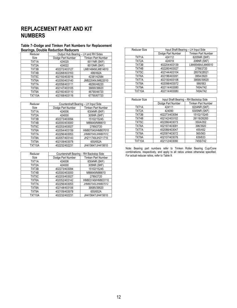
REPLACEMENT PART AND KIT NUMBERS Table 7–Dodge and Timken Part Numbers for Replacement Bearings, Double Reduction Reducers
Output Hub Bearing – LH and RH Sides Reducer Size Dodge Part Number Timken Part Number
TXT1A 424020 6011NR (SKF) TXT2A 424022 6013NR (SKF) TXT3B 402272/403127 LM814849/LM814810 TXT4B 402268/403163 498/492A TXT5C 402193/403016 42381/42584 TXT6A 402050/403140 JM822049/JM822010 TXT7A 402058/403111 48290/48220 TXT8A 402147/403105 36690/36620 TXT9A 402160/403110 46790/46720
TXT10A 402168/403116 67790/67720
Countershaft Bearing – LH Input Side Reducer Size Dodge Part Number Timken Part Number
TXT1A 424006 6304NR (SKF) TXT2A 424000 305NR (SKF) TXT3B 402273/403094 15102/15245 TXT4B 402000/403000 M86649/M86610 TXT5C 402203/403027 2789/2720 TXT6A 402054/403159 HM807040/HM807010 TXT7A 402256/403053 JHM807045/JHM807012 TXT8A 402057/403143 JH211749/JH211710 TXT9A 402109/403078 655/652A
TXT10A 402232/402231 JH415647/JH415610
Countershaft Bearing – RH Backstop Side Reducer Size Dodge Part Number Timken Part Number
TXT1A 424006 6304NR (SKF) TXT2A 424000 305NR (SKF) TXT3B 402273/403094 15102/15245 TXT4B 402000/403000 M86649/M86610 TXT5C 402203/403027 2789/2720 TXT6A 402052/403142 HM803149/HM803110 TXT7A 402256/403053 JHM807045/JHM807012 TXT8A 402148/403106 39585/39520 TXT9A 402109/403078 655/652A
TXT10A 402232/402231 JH415647/JH415610
Input Shaft Bearing – LH Input Side Reducer Size Dodge Part Number Timken Part Number
TXT1A 424112 6205NR (SKF) TXT2A 424019 206NR (SKF) TXT3B 402204/403139 LM48548A/LM48510 TXT4B 402280/403027 2788/2720 TXT5C 402144/403104 28579/28521 TXT6A 402196/403091 395A/3920 TXT7A 402150/403106 39590/39520 TXT8A 402098/403072 566/563 TXT9A 402114/403080 745A/742
TXT10A 402114/403080 745A/742
Input Shaft Bearing – RH Backstop Side Reducer Size Dodge Part Number Timken Part Number
TXT1A 424111 6204NR (SKF) TXT2A 424090 6305NR (SKF) TXT3B 402273/403094 15102/15245 TXT4B 402142/403102 26118/26283 TXT5C 402266/403073 350A/352 TXT6A 402197/403091 396/3920 TXT7A 402088/403047 455/452 TXT8A 402097/403072 565/563 TXT9A 402107/403076 639/633 TXT10A 402112/403080 745S/742
Note: Bearing part numbers refer to Timken Roller Bearing Cup/Cone combinations, respectively, and apply to all ratios unless otherwise specified. For actual reducer ratios, refer to Table 9.

13
Table 8 – Replacement Parts Kit Numbers
Output Hub Assembly Reducer Size Ratio Seal Kit Taper Hub Straight Hub Countershaft Assembly Bearing Kit(s)
9:1 392100 15:1 392090 TXT1A 25:1
392119 390878 390151 392091
389905 All
9:01 392101 15:1 392092 TXT2A 25:1
392120 392111 392110 392093
389906 All
9:1 389729 15:1 389700 TXT3B 25:1
389720 389703 389702 389701
389587 Input 389588 C/S
389589 Output 9:1 389730
15:1 389707 TXT4B 25:1
389721 389710 389709 389708
389590 Input 389591 C/S
389592 Output 9:1 389731
15:1 389714 TXT5C 25:1
389722 389717 389716 389715
389593 Input 389595 C/S
389596 Output 9:1 392140
15:1 391171 TXT6A 25:1
246340 390935 390988 391186
N/A
9:1 392141 15:1 391196 TXT7A 25:1
247345 390941 390990 391197
N/A
15:1 391184 TXT8A 25:1 248340 390944 390993 391185 N/A
15:1 390124 TXT9A 26:1 249340 390949 390159 390139 N/A
15:1 390983 TXT10A 24:1 272460 390954 390160 390998 N/A
Notes: Seal Kit consists of Input Seal, Output Seals, Backstop Cover Gasket and RTV Sealant. Output Hub Assembly consists of Output Hub, Output Gear and Gear Key. Countershaft Assembly consists of Countershaft Pinion, Countershaft Gear and Gear Key. Bearing Kit consists of LH and RH Output Bearing Cup/Cone, LH and RH Countershaft Bearing Cup/Cone (double reduction only) and LH and RH Input Bearing Cup/Cone.

14
Parts for TXT/HXT 1A & 2A Straight and Tapered Bushed Double Reduction Reducers

15
Parts for TXT/HXT 1A & 2A Straight and Tapered Bushed Double Reduction Reducers
Ref. Description Qty. TXT/HXT 1 TXT/HXT 2
12 Backstop Assembly 1 242101 252101 1 Housing-LH 1 241358 242353 2 Housing-RH 1 241359 242354 Housing-RH, Flange Mount Drilled 1 241387 242393
3 Housing-Hydroil LH 1 241064 242067 § RTV Sealant, Tube 1 465044 465044 § Air Vent 1 900287 900287 16 Housing Bolt † 411418 411418 18 Housing Bolt-Adapter 2 411420 411420 20 Lock-Washer ‡ 419011 419011 22 Hex Nut ‡ 407087 407087 § Dowel Pin 2 420145 420145 § Magnetic Oil Plug 1 430060 430060 25 Oil Plug 4 430031 430031 34 Backstop Shaft Cover 1 242221 243221 38 Backstop Cover Screw 4 415022 415022
Seal Kit ♦ 1 392119 392120
36 Backstop Cover Gasket ▲ 1 242220 243220 42 Input Oil Seal ▲ 1 241457 242211 78 Output Hub Oil Seal ▲ 2 241210 242210
40 Input Pinion
9:1 Ratio ♠ 1 241481 242481 15:1 Ratio ♠ 1 241302 242186 25:1 Ratio ♠ 1 241200 242187
130 Hydroil Input Pinion 15:1 Ratio ♠ 1 241455 242188 25:1 Ratio ♠ 1 241449 242189
41 Input Pinion Key 1 443008 443014 Bearing Replacement Kit ♦ 1 389905 389906
44 Input Pinion Bearing-LH, Input Side▲ 1 424112 424019 46 Input Pinion Bearing-RH, Backstop Side▲ 1 424111 424090 54 Countershaft Pinion Bearing ▲ 2 424006 424000 80 Output Hub Bearings ▲ 2 424020 424022
Countershaft Pinion Assembly ♦ 9:1 Ratio ♠ 1 392100 392101 15:1 Ratio ♠ 1 392090 392092 25:1 Ratio ♠ 1 392091 392093
48 Countershaft Pinion ▲ 1 241216 242185 50 First Reduction Gear ▲
9:1 Ratio ♠ 1 241482 242482 15:1 Ratio ♠ 1 241170 242008 25:1 Ratio ♠ 1 241171 242005
52 Countershaft to First Gear Key ▲ 1 241309 242218 Taper Bore Output Hub Assembly ♦ 1 390878 392111 Straight Bore Output Hub Assembly ♣ 1 390151 392110
60 Output Hub Straight Bore ■ 1 241208 242208 Taper Bore ▲ 1 241265 242134
62 Output Gear ▲■ 1 241007 242181 64 Output Gear Key ▲■ 1 241217 443399 59 Output Hub Snap Ring ▲ 2 421013 421017 61 Straight Bore Output Hub Key ■ 1 241296 242296
68 Straight Bore Output Hub Collar 2 241209 242209 70 Straight Bore Output Hub Collar Screw 4 400062 400094 72 Taper Bore Bushing Backup Plate 2 241266 242137 74 Bushing Backup Plate Retaining Ring 2 421111 421112
84 Taper Bore Bushing Assembly ♦
Bushing ▲ 1” Bore 1 241278 N/A 1-1/16” Bore 1 241280 N/A 1-1/8” Bore 1 241282 242146
16
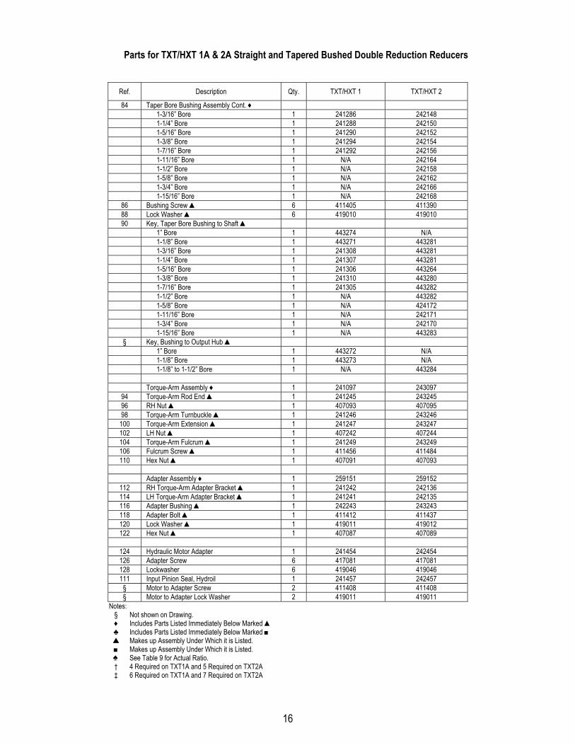
Parts for TXT/HXT 1A & 2A Straight and Tapered Bushed Double Reduction Reducers
Ref. Description Qty. TXT/HXT 1 TXT/HXT 2
84 Taper Bore Bushing Assembly Cont. ♦ 1-3/16” Bore 1 241286 242148 1-1/4” Bore 1 241288 242150 1-5/16” Bore 1 241290 242152 1-3/8” Bore 1 241294 242154 1-7/16” Bore 1 241292 242156 1-11/16” Bore 1 N/A 242164 1-1/2” Bore 1 N/A 242158 1-5/8” Bore 1 N/A 242162 1-3/4” Bore 1 N/A 242166 1-15/16” Bore 1 N/A 242168
86 Bushing Screw ▲ 6 411405 411390 88 Lock Washer ▲ 6 419010 419010 90 Key, Taper Bore Bushing to Shaft ▲
1” Bore 1 443274 N/A 1-1/8” Bore 1 443271 443281 1-3/16” Bore 1 241308 443281 1-1/4” Bore 1 241307 443281 1-5/16” Bore 1 241306 443264 1-3/8” Bore 1 241310 443280 1-7/16” Bore 1 241305 443282 1-1/2” Bore 1 N/A 443282 1-5/8” Bore 1 N/A 424172 1-11/16” Bore 1 N/A 242171 1-3/4” Bore 1 N/A 242170 1-15/16” Bore 1 N/A 443283 § Key, Bushing to Output Hub ▲ 1” Bore 1 443272 N/A 1-1/8” Bore 1 443273 N/A 1-1/8” to 1-1/2” Bore 1 N/A 443284 Torque-Arm Assembly ♦ 1 241097 243097
94 Torque-Arm Rod End ▲ 1 241245 243245 96 RH Nut ▲ 1 407093 407095 98 Torque-Arm Turnbuckle ▲ 1 241246 243246 100 Torque-Arm Extension ▲ 1 241247 243247 102 LH Nut ▲ 1 407242 407244 104 Torque-Arm Fulcrum ▲ 1 241249 243249 106 Fulcrum Screw ▲ 1 411456 411484 110 Hex Nut ▲ 1 407091 407093
Adapter Assembly ♦ 1 259151 259152
112 RH Torque-Arm Adapter Bracket ▲ 1 241242 242136 114 LH Torque-Arm Adapter Bracket ▲ 1 241241 242135 116 Adapter Bushing ▲ 1 242243 243243 118 Adapter Bolt ▲ 1 411412 411437 120 Lock Washer ▲ 1 419011 419012 122 Hex Nut ▲ 1 407087 407089
124 Hydraulic Motor Adapter 1 241454 242454 126 Adapter Screw 6 417081 417081 128 Lockwasher 6 419046 419046 111 Input Pinion Seal, Hydroil 1 241457 242457
§ Motor to Adapter Screw 2 411408 411408 § Motor to Adapter Lock Washer 2 419011 419011
Notes: § Not shown on Drawing. ♦ Includes Parts Listed Immediately Below Marked ▲ ♣ Includes Parts Listed Immediately Below Marked ■ ▲ Makes up Assembly Under Which it is Listed. ■ Makes up Assembly Under Which it is Listed. ♠ See Table 9 for Actual Ratio. † 4 Required on TXT1A and 5 Required on TXT2A ‡ 6 Required on TXT1A and 7 Required on TXT2A

17
Parts for TXT3B thru TXT5C Straight and Tapered Bushed Double Reduction Reducer

18
Parts for TXT3B thru TXT5C Straight and Tapered Bushed Double Reduction Reducer
Ref. Description Qty. TXT3B HXT3B
TXT4B HXT4B
TXT5C HXT5C
12 Backstop Assembly 1 243106 244106 245154 1 Housing-TXT and Hydroil LH 1 243228 244365 245369 2 Housing-RH 1 243229 244366 245370 Housing-RH, Flange Mount Drilled 1 243384 244387 245373 § RTV Sealant, Tube 1 465044 465044 465044 § Air Vent 1 900287 900287 904287 16 Housing Bolt 6 411440 411442 411464 18 Housing Bolt-Adapter 2 411442 411444 411466 20 Lock-Washer 8 419012 419012 419013 22 Hex Nut 8 407089 407089 407091 § Dowel Pin 2 420146 420146 420147 § Magnetic Oil Plug 1 430060 430060 430062 25 Oil Plug 4 430031 430031 430033 28 Input Shaft Seal Carrier 1 243543 244577 245597 30 Input Shaft Bearing Shim Pack ‡ 389704 389711 389732 32 Input Seal Carrier Screw † 411390 411407 411407 33 Lock Washer † 419010 419011 419011 34 Backstop Cover 1 243560 244493 245226 38 Backstop Cover Screw 4 416524 411035 411394 39 Backstop Cover Lock Washer 4 N/A N/A 419009
Seal Kit ♦ 1 389720 389721 389722
36 Backstop Cover Gasket ▲ 1 243561 244593 245220 42 Input Pinion Shaft Seal ▲ 1 243558 244524 355011 78 Output Hub Oil Seal ▲ 2 243578 244673 245545
40 Input Pinion
9:1 Ratio ♠ 1 243549 244579 245599 15:1 Ratio ♠ 1 243550 244580 245600 25:1 Ratio ♠ 1 243551 244581 245601
130 15:1 Ratio Hydroil Pinion ♠ 1 243553 244583 245603 25:1 Ratio Hydroil Pinion ♠ 1 243554 244584 245604 15:1 Ratio Hydroil 6-B Pinion ♠ 1 N/A 244586 N/A 25:1 Ratio Hydroil 6-B Pinion ♠ 1 243498 244587 245641
41 Input Pinion Shaft Key 1 443032 443082 443096 Input Bearing Kit ♦ 1 389587 389590 389594
44 Input Shaft Bearing Cone, Input Side ▲ 1 402204 402280 402144 45 Input Shaft Bearing Cup, Input Side ▲ 1 403139 403027 403104 46 Input Shaft Bearing Cone, Backstop Side ▲ 1 402273 402142 402266 47 Input Shaft Bearing Cup, Backstop Side ▲ 1 403094 403102 403073
Countershaft Pinion Assembly ♦ 9:1 Ratio ♠ 1 389729 389730 389731 15:1 Ratio ♠ 1 389700 389707 389714 25:1 Ratio ♠ 1 389701 389708 389715
48 Countershaft Pinion ▲ 1 243555 244590 245596 50 First Reduction Gear ▲
9:1 Ratio ♠ 1 243237 244482 245482 15:1 Ratio ♠ 1 243238 244214 245214 25:1 Ratio ♠ 1 243239 244212 245212
52 First Stage Gear Key ▲ 1 243215 244215 244215 Countershaft Bearing Kit ♦ 1 389588 389591 389595
54 Countershaft Bearing Cone, Input Side ▲ 1 402273 402000 402203 55 Countershaft Bearing Cup, Input Side ▲ 1 403094 403000 403027 56 Countershaft Bearing Cone, Backstop Side ▲ 1 402273 402000 402203 57 Countershaft Bearing Cup, Backstop Side ▲ 1 403094 403000 403027 58 Countershaft Bearing Cover, Input Side ▲ 1 243545 244578 245594 59 Countershaft Bearing Shim Pack ‡ 389705 389712 389718
Taper Bore Output Hub Assembly ♦ 1 389703 389710 389717 Straight Bore Output Hub Assembly ♣ 1 389702 389709 389716
60 Output Hub Straight Bore ■ 1 243557 244589 245591 Taper Bore ▲ 1 243556 244588 245590
62 Output Gear ▲■ 1 243570 244188 245186

19
Parts for TXT3B thru TXT5C Straight and Tapered Bushed Double Reduction Reducer
Ref. Description Qty. TXT3B HXT3B
TXT4B HXT4B
TXT5C HXT5C
64 Output Gear Key ▲■ 1 243216 354087 355064
68 Output Hub Collar, Straight Bore 2 243572 244658 245598 70 Output Hub Collar Screw 4 400098 400150 400154 72 Bushing Backup Plate, Taper Bore 2 243308 244099 245114 74 Bushing Backup Plate Retaining Ring 2 421109 421108 421107
76 Output Hub Seal Carrier, Input Side 1 243547 244591 245592
Output Hub Bearing Kit ♦ 1 389589 389592 389596
80 Output Hub Bearing, Cone ▲ 2 402272 402268 402193 81 Output Hub Bearing, Cup ▲ 2 403127 403163 403016 82 Output Hub Bearing Shim Kit ‡ 389706 389713 389719
84 Taper Bore Bushing Assembly ♦
Bushing ▲ 1-5/16” Bore 1 243282 N/A N/A 1-3/8” Bore 1 243284 N/A N/A 1-7/16” Bore 1 243260 244079 N/A 1-1/2” Bore 1 243262 244081 N/A 1-5/8” Bore 1 243264 244083 N/A 1-11/16” Bore 1 243268 244085 N/A 1-3/4” Bore 1 243266 244087 N/A 1-7/8” Bore 1 243270 244089 245084 1-15/16” Bore 1 243272 244093 245086 2” Bore 1 243274 244095 245088 2-1/8” Bore 1 N/A 244109 N/A 2-3/16” Bore 1 243276 244111 245090 2-1/4” Bore 1 N/A 244113 245092 2-7/16” Bore 1 N/A 244115 245094 2-1/2” Bore 1 N/A N/A 245099 2-11/16” Bore 1 N/A N/A 245110 2-15/16” Bore 1 N/A N/A 245112
86 Taper Bushing Screw ▲ 6 411407 411408 411435 88 Taper Bushing Lockwasher ▲ 6 419011 419011 419012
90 Key, Bushing to Shaft ▲
1-5/16” Bore 1 443264 N/A N/A 1-3/8” Bore 1 443264 N/A N/A 1-7/16” Bore 1 443265 443254 N/A 1-1/2” Bore 1 443265 443254 N/A 1-5/8” Bore 1 443265 443254 N/A 1-11/16” Bore 1 443266 443254 N/A 1-3/4” Bore 1 443266 443254 N/A 1-7/8” Bore 1 443267 443255 443251 1-15/16” Bore 1 443269 443255 443251 2” Bore 1 443268 443255 443251 2-1/8” Bore 1 N/A 443258 N/A 2-3/16” Bore 1 443270 443259 443251 2-1/4” Bore 1 N/A 443260 443251 2-7/16” Bore 1 N/A 443261 443243 2-1/2” Bore 1 N/A N/A 443244 2-11/16” Bore 1 N/A N/A 443245 2-15/16” Bore 1 N/A N/A 443250 § Key, Bushing to Output Hub ▲ 1-3/4” thru 1-15/16” Bore Bushing 1 443262 N/A N/A 1-7/16” thru 2-1/4” Bore Bushing 1 N/A N/A 443202 2-3/16” thru 2-15/16” Bore Bushing 1 N/A 443257 N/A Torque-Arm Rod Kit ♦ 1 243097 245097 245097
94 Torque-Arm Rod End ▲ 1 243245 245245 245245 96 RH Nut ▲ 1 407095 407097 407097 98 Torque-Arm Turnbuckle ▲ 1 243246 245246 245246 100 Torque-Arm Extension ▲ 1 243247 245247 245247 102 LH Nut ▲ 1 407244 407246 407246 104 Fulcrum ▲ 1 243249 246249 246249 106 Fulcrum Screw ▲ 1 411484 411484 411484 110 Hex Nut ▲ 1 407093 407093 407093

20
Parts for TXT3B thru TXT5C Straight and Tapered Bushed Double Reduction Reducer
Ref. Description Qty. TXT3B HXT3B
TXT4B HXT4B
TXT5C HXT5C
Adapter Assembly ♦ 1 259153 259154 259155 112 RH Adapter Plate ▲ 1 243242 244244 245242 114 LH Adapter Plate ▲ 1 243241 244243 245241 116 Adapter Bushing ▲ 1 243243 245243 245243 118 Adapter Bolt ▲ 1 411437 411460 411460 120 Lockwasher ▲ 1 419012 419013 419013 122 Hex Nut ▲ 1 407089 407091 407091 Hydroil Motor Adapter 124 15:1 Ratio Motor Adapter 1 243539 244572 245606
25:1 Ratio Motor Adapter 1 243541 244572 245607 Hydroil 6-B Motor Adapter, 15:1 and 25:1 Ratio 1 243467 244573 245643
126 Adapter Screw † 417081 417108 415023 128 Lockwasher † 419046 419047 419047
§ Motor to Adapter Screw § Motor to Adapter Lock Washer
Notes: § Not shown on drawing. ♦ Includes parts listed immediately below marked ▲ ♣ Includes parts listed immediately below marked ■ ▲ Makes up assembly under which it is listed. ■ Makes up assembly under which it is listed. ♠ See Table 9 for actual ratio. † 4 required on TXT3B and TXT4B, 5 required on TXT5C ‡ Two sets recommended.

21
Parts for TXT6A thru TXT10A Straight and Tapered Bushed Double Reduction Reducers

22
Parts for TXT6A thru TXT10A Straight and Tapered Bushed Double Reduction Reducers
Ref. Description Qty. TXT6A TXT7A TXT8A TXT9A TXT10A
12 Backstop Assembly 1 246092 247260 249260 249260 250260 1 Housing-TXT and Hydroil LH 1 246358 247358 248358 249358 250358 2 Housing-RH 1 246359 247359 248359 249359 250359 Housing-RH, Flange Mount Drilled 1
§ RTV Sealant, Tube 1 465044 465044 465044 465044 465044 § Air Vent 1 904287 904287 904287 904287 904287 16 Housing Bolt 411466 411498 411499 411500 411502 18 Housing Bolt-Adapter 2 411468 411499 411502 411502 411506 20 Lock-Washer 419013 419016 419016 419016 419016 22 Hex Nut 407091 407095 407095 407095 407095 § Dowel Pin 2 420147 420148 420148 420148 420148 25 Magnetic Oil Plug 1 430062 430064 430064 430064 430064 § Oil Plug 4 430033 430035 430035 430035 430035 28 Input Shaft Seal Carrier 1 246184 247320 258023 249211 249211 30 Input Shaft Bearing Shim Pack ‡ 391164 390420 390038 390168 390168 32 Carrier and Cover Screw ∆ 411408 411433 411408 411408 411408 33 Lock Washer ∆ 419011 419012 419011 419011 419011 34 Backstop Cover 1 246226 246226 248226 248226 248226 35 Backstop Retaining Ring † 421029 421029 421034 421034 421034 38 Backstop Cover Screw 6 411394 411394 411394 411394 411394 39 Backstop Cover Lock Washer 6 419009 419009 419009 419009 419009
Seal Kit ♦ 1 246340 247345 248340 249340 272460
36 Backstop Cover Gasket ▲ 1 246220 246220 248220 248220 248220 42 Input Pinion Shaft Seal ▲ 1 242210 242210 248211 248211 248211 78 Output Hub Oil Seal ▲ 2 246310 247310 258019 249210 250010
40 Input Pinion
9:1 Ratio ♠ 1 246481 247479 N/A N/A N/A 15:1 Ratio ♠ 1 246290 247370 248370 272074 250300 25:1 Ratio ♠ □ 1 246291 247371 248371 272106 250004
130 15:1 Ratio Hydroil Pinion ♠ 1 246230 247463 N/A N/A N/A 25:1 Ratio Hydroil Pinion ♠ 1 246286 247462 N/A N/A N/A 15:1 Ratio 6B Hydroil Pinion ♠ 1 N/A N/A N/A N/A N/A 25:1 Ratio 6B Hydroil Pinion ♠ 1 246521 247521 N/A N/A N/A
41 Input Pinion Shaft Key 1 443113 443127 443133 443123 443123 Input Bearings
44 Input Shaft Bearing Cone, Input Side 1 402196 402150 402098 402114 402114 45 Input Shaft Bearing Cup, Input Side 1 403091 403106 403072 403080 403080 46 Input Shaft Bearing Cone, Backstop Side 1 402197 402088 402097 402107 402112 47 Input Shaft Bearing Cup, Backstop Side 1 403091 403047 403072 403076 403080
Countershaft Pinion Assembly ♦ 9:1 Ratio ♠ 1 392140 392141 N/A N/A N/A 15:1 Ratio ♠ 1 391171 391196 391184 390124 390983 25:1 Ratio ♠ □ 1 391186 391197 391185 390139 390998
48 Countershaft Pinion ▲ 1 246294 247002 248002 249006 272249 50 First Reduction Gear ▲
9:1 Ratio ♠ 1 246482 247478 N/A N/A N/A 15:1 Ratio ♠ 1 246292 247008 248213 249008 250301 25:1 Ratio ♠ □ 1 246293 247005 248214 249005 250005
52 First Stage Gear Key ▲ 1 245218 247218 248218 248218 248218 Countershaft Bearings
54 Countershaft Bearing Cone, Input Side 1 402054 402256 402057 402109 402232 55 Countershaft Bearing Cup, Input Side 1 403159 403053 403143 403078 402231 56 Countershaft Bearing Cone, Backstop Side 1 402052 402256 402148 402109 402232 57 Countershaft Bearing Cup, Backstop Side 1 403142 403053 403106 403078 402231 58 Countershaft Bearing Cover, Input Side 1 246185 247194 248223 249225 272251 59 Countershaft Bearing Shim Pack ‡ 391165 390429 391182 390168 390575
Taper Bore Output Hub Assembly ♦ 1 390935 390941 390944 390949 390954 Straight Bore Output Hub Assembly ♣ 1 390988 390990 390993 390159 390160
60 Straight Bore Hub ■ 1 246338 247338 248332 250090 250008 Taper Bore Hub ▲ 1 246269 272137 272036 249140 272241
62 Output Gear ▲■ 1 246295 247215 248215 021764 250007 64 Output Gear Key ▲■ 2 245217 245217 248217 443413 250017

23
Parts for TXT6A thru TXT10A Straight and Tapered Bushed Double Reduction Reducers
Ref. Description Qty. TXT6A TXT7A TXT8A TXT9A TXT10A
68 Output Hub Collar, Straight Bore 2 246309 247309 248209 249209 250009 70 Output Hub Collar Screw 4 400154 400190 400190 400194 400194
72 Bushing Backup Plate, Taper Bore 2 246270 272138 272037 272082 272242 74 Output Hub Retaining Ring 2 421055 421099 421098 421097 421069 76 Output Hub Seal Carrier, Input Side 1 246187 247315 258021 249221 250011
Output Hub Bearing Kit 1
80 Output Hub Bearing, Cone 2 402050 402058 402147 402160 402168 81 Output Hub Bearing, Cup 2 403140 403111 403105 403110 403116 82 Output Hub Bearing Shim Kit ‡ 391187 390044 390048 390171 390172
84 Taper Bore Bushing Assembly ♦
Bushing ▲ 2-3/16” Bore 1 246261 N/A N/A N/A N/A 2-1/4” Bore 1 246262 N/A N/A N/A N/A 2-7/16” Bore 1 246263 272125 N/A N/A N/A 2-1/2” Bore 1 246264 N/A N/A N/A N/A 2-11/16” Bore 1 246265 272147 N/A N/A N/A 2-13/16” Bore 1 N/A 272130 N/A N/A N/A 2-7/8” Bore 1 246266 272131 N/A N/A N/A 2-15/16” Bore 1 246267 272132 272048 N/A N/A 3” Bore 1 246283 272133 N/A N/A N/A 3-3/16” Bore 1 N/A 272134 N/A N/A N/A 3-7/16” Bore 1 246268 272135 272032 272056 N/A 3-15/16” Bore 1 N/A 272136 272033 272077 272214 4-3/16” Bore 1 N/A N/A 272034 N/A N/A 4-7/16” Bore 1 N/A N/A 272035 272079 272238 4-15/16” Bore 1 N/A N/A N/A 272080 272239 5-7/16” Bore 1 N/A N/A N/A N/A 272240
86 Taper Bushing Screw ▲ 6 411435 411456 411457 411484 411484 88 Taper Bushing Lockwasher ▲ 6 419012 419013 419013 419014 419014
90 Key, Bushing to Shaft ▲
2-3/16” Bore 1 443211 N/A N/A N/A N/A 2-1/4” Bore 1 443211 N/A N/A N/A N/A 2-7/16” Bore 1 443214 443248 N/A N/A N/A 2-1/2” Bore 1 443214 N/A N/A N/A N/A 2-11/16” Bore 1 443238 443248 N/A N/A N/A 2-13/16” Bore 1 N/A 443199 N/A N/A N/A 2-7/8” Bore 1 443236 443199 N/A N/A N/A 2-15/16” Bore 1 443237 443199 443247 N/A N/A 3” Bore 1 443252 443216 N/A N/A N/A 3-3/16” Bore 1 N/A 443235 N/A N/A N/A 3-7/16” Bore 1 443213 443217 443171 443249 N/A 3-15/16” Bore 1 N/A 443218 443173 272119 443192 4-3/16” Bore 1 N/A N/A 443174 N/A N/A 4-7/16” Bore 1 N/A N/A 443196 272066 443193 4-15/16” Bore 1 N/A N/A N/A 443161 443194 5-7/16” Bore 1 N/A N/A N/A N/A 443195 1 § Key, Bushing to Output Hub ▲ 2-3/16” thru 2-1/2” Bore Bushing 1 443212 N/A N/A N/A N/A 2-7/16” thru 3” Bore Bushing 1 N/A 443198 N/A N/A N/A 2-3/16” thru 2-15/16” Bore Bushing 1 N/A N/A N/A N/A N/A 2-15/16” thru 3-7/16” Bore Bushing 1 N/A N/A 443162 N/A N/A 3-7/16” thru 4-3/16” Bore Bushing 1 N/A N/A N/A 443121 N/A 3-15/16” thru 4-7/16” Bore Bushing 1 N/A N/A N/A N/A 443191 Torque-Arm Rod Kit ♦ 1 246097 247098 390129 390129 390129
94 Torque-Arm Rod End ▲ 1 245245 247239 271050 271050 271050 96 RH Nut ▲ 1 407097 407099 407104 407104 407104 98 Torque-Arm Turnbuckle ▲ 1 245246 247246 271051 271051 271051 100 Torque-Arm Extension ▲ 1 245247 247240 271052 271052 271052 102 LH Nut ▲ 1 407246 407248 407250 407250 407250 104 Fulcrum ▲ 1 247248 247248 271054 271054 271054 106 Fulcrum Screw ▲ 1 411489 411489 411516 411516 411516 108 Lockwasher ▲ 419014 419014 419020 419020 419020 110 Hex Nut ▲ 1 407093 407093 407099 407099 407099

24
Parts for TXT6A thru TXT10A Straight and Tapered Bushed Double Reduction Reducers
Ref. Description Qty. TXT6A TXT7A TXT8A TXT9A TXT10A
Adapter Assembly ♦ 1 259156 259157 248110 249110 250110 112 RH Adapter Plate ▲ 1 246242 247242 272053 249241 250041 114 LH Adapter Plate ▲ 1 246241 247241 272053 249241 250041 116 Adapter Bushing ▲ 1 245243 247244 271046 271046 211046 118 Adapter Bolt ▲ 1 411460 411489 411510 411512 411512 120 Lockwasher ▲ 1 419013 419014 419020 419020 419020 122 Hex Nut ▲ 1 407091 407093 407099 407099 407099
124 Hydroil Motor Adapter 1 246465 247464 N/A N/A N/A
Hydroil 6B Motor Adapter 1 246522 247522 N/A N/A N/A 126 Hydroil Adapter Screw 6 417108 417141 N/A N/A N/A 128 Lockwasher 6 906406 907406 N/A N/A N/A
§ Motor to Adapter Screw § Motor to Adapter Lock Washer
Notes: § Not shown on drawing. ♦ Includes parts listed immediately below marked “▲”. ▲ Makes up assembly under which it is listed. ♣ Includes parts listed immediately below marked “■”. ■ Makes up assembly under which it is listed. ♠ See Table 9 for actual ratio. † Required only with optional backstop, 1 required on TXT6A and TXT7A, 2 required on TXT8A, TXT9A, & TXT10A. ‡ 2 sets recommended. ∆ 18 Required on TXT6A, 20 Required on TXT7A, and 24 Required on TXT8A, TXT9A, & TXT10A. □ Nominal Ratio on TXT6A, TXT7A, and TXT8A is 25:1, Nominal Ratio on TXT9A is 26:1, and Nominal Ratio on TXT10A is 24:1.
ACTUAL RATIOS Table 9 – Actual Ratios
Nominal Ratios Reducer Size 9:1 15:1 25:1*
TXT1A 9.44 15.35 25.64 TXT2A 9.25 14.10 23.46 TXT3B 8.91 14.88 24.71 TXT4B 9.67 15.13 24.38 TXT5C 8.95 15.40 25.56 TXT6A 9.20 15.33 25.13 TXT7A 9.61 15.23 24.59 TXT8A N/A 15.08 24.62 TXT9A N/A 15.12 25.66
TXT10A N/A 15.16 24.30 * TXT9A is 26:1 Nominal Ratio and TXT10A is 24:1 Nominal Ratio


![regular expressions · file-201[23]0101\.txt file-20120101.txt file-20130101.txt file-20110101.txt Character Sets](https://img.pdfslide.us/doc/110x75/5fd6b8f258e3c00b8d231dde/regular-file-201230101txt-file-20120101txt-file-20130101txt-file-20110101txt.jpg)