Embed Size (px)
Citation preview
Early Entrance Coproduction PlantPhase I - Quarterly Report No. 4
Reporting period: July 1, 2000 – September 30, 2000
Principal Contributors: John S. Abughazaleh (KBR)Mushtaq Ahmed (Praxair)Ashok Anand (GE)John H. Anderson (TESI)Charles Benham (Rentech)Fred D. Brent (Texaco)Thomas E. Chance (GE)William K. Davis (Texaco)Raymond F. Drnevich (Praxair)Larry Hall (KBR)Ming He (Texaco)Stephen A. Lang (KBR)Jimmy O. Ong (Texaco)Sarah J. Patel (Texaco)George Potoczniak (KBR)Adela G. Sanchez (Texaco)Charles H. Schrader (TESI)Lalit S. Shah (Texaco)Phil J. Shires (KBR)Rae Song (Texaco)
Date Issued: December 18, 2000 (Preliminary)February 15, 2001 (Final)
DOE Cooperative AgreementNo. DE-FC26-99FT40658
Texaco Energy Systems, Inc.1111 Bagby St.Houston, Tx. 77007

DOE – Early Entrance Coproduction Plant
Cooperative Agreement No. DE-FC26-99FT40658 2
Disclaimer:This report was prepared as an account of work sponsored by an agency of the UnitedStates Government. Neither the United States Government nor any agency thereof,nor any of their employees, makes any warranty, express or implied, or assumes anylegal liability or responsibility for the accuracy, completeness, or usefulness of anyinformation, apparatus, product, or process disclosed, or represents that its use wouldnot infringe privately owned rights. Reference herein to any specific commercialproduct, process, or service by trade name, trademark, manufacturer, or otherwisedoes not necessarily constitute or imply its endorsement, recommendation, orfavoring by the United States Government or any agency thereof. The views andopinions of authors expressed herein do not necessarily state or reflect those of theUnited States Government or any agency thereof.
DOE – Early Entrance Coproduction Plant
Cooperative Agreement No. DE-FC26-99FT40658 3
Abstract:The overall objective of this project is the three phase development of an EarlyEntrance Coproduction Plant (EECP) which produces at least one product from atleast two of the following three categories: (1) electric power (or heat), (2) fuels, and(3) chemicals. The objective is to have these products produced by technologiescapable of using synthesis gas derived from coal and/or other carbonaceousfeedstocks.
The objective of Phase I is to determine the feasibility and define the concept for theEECP located at a specific site and to develop a Research, Development, and TestingPlan (RD&T) for implementation in Phase II.
The objective of Phase II is to implement the RD&T as outlined in the Phase I RD&TPlan to enhance the development and commercial acceptance of coproductiontechnology that produces high-value products, particularly those that are critical toour domestic fuel and power requirements. The project will resolve criticalknowledge and technology gaps on the integration of gasification and downstreamprocessing to coproduce some combination of power, fuels, and chemicals from coaland/or other carbonaceous feedstocks.
The objective of Phase III is to develop an engineering design package and afinancing plan for an EECP located at a specific site.
The project’s intended result is to provide the necessary technical, economic, andenvironmental information that will be needed to move the EECP forward to detaileddesign, construction, and operation by industry.

DOE – Early Entrance Coproduction Plant
Cooperative Agreement No. DE-FC26-99FT40658 4
Table of Contents
I. List of Figures and Tables ........................................................................................ 5II. List of Acronyms ...................................................................................................... 6III. Executive Summary.................................................................................................. 7IV. Results, Discussion and Preliminary Conclusions.................................................... 8V. List of Major Activities for 3Q2000....................................................................... 18VI. List of Planned Activities for 4Q2000.................................................................... 19VII.Graphs:
A. Phase I, Planned Expenditures vs. Actual Expenditures .............................. 21B. Phase I, Planned DOE Expenditures vs. Actual DOE Expenditures............ 22C. Phase I, Planned vs. Actual Progress............................................................ 23
VIII. Schedule – MS Project schedule updated through September 30, 2000 ............... 25

DOE – Early Entrance Coproduction Plant
Cooperative Agreement No. DE-FC26-99FT40658 5
I. List of FiguresThe following figures were used in this report:
Figure 1 - Overall Block Flow Diagram for PAR Finished Wax case . . . . . . 17Graph – Phase I Total Expenditures vs. Plan . . . . . . . . . . . . . . . . . . . . . . . . 21Graph – Phase I Total DOE Expenditures vs. Plan . . . . . . . . . . . . . . . . . . . . 22Graph – Phase I Total Percent Complete . . . . . . . . . . . . . . . . . . . . . . . . . . . . 23
DOE – Early Entrance Coproduction Plant
Cooperative Agreement No. DE-FC26-99FT40658 6
II. List of AcronymsThe following acronyms were used in this report:
AGR....................................................................................................................Acid gas removalASU .................................................................................................................Air Separation UnitBACT..................................................................................... Best Available Control TechnologyBFW..................................................................................................................... Boiler feedwaterbpd .......................................................................................................................... barrels per dayCO2 ........................................................................................................................ Carbon dioxideDCU..............................................................................................................Delayed Coking UnitDOE ...................................................................................... United States Department of EnergyEECP....................................................................................... Early Entrance Coproduction PlantF-T ........................................................................................................................Fischer-TropschGE................................................................................................General Electric Power SystemsGT.................................................................................................................................Gas turbineH2S...................................................................................................................... Hydrogen sulfideH2SO4........................................................................................................................ Sulfuric AcidHCU................................................................................................................Hydrocracking UnitHP .............................................................................................................................High pressureHRSG.......................................................................................... Heat Recovery Steam GeneratorIP...................................................................................................................Intermediate pressureKBR .................................................................................................. Kellogg Brown & Root, Inc.LP.............................................................................................................................. Low pressureMDEA.........................................................................................................MethyldiethanolamineNOx....................................................................................................................... Nitrogen oxidesNPV ...................................................................................................................Net Present ValuePAR.....................................................................................Motiva’s Port Arthur, Texas RefineryPARFW..........................................................................Port Arthur Refinery Finished Wax CasePARHCU ..................................................................... Port Arthur Refinery Hydrocracking CaseRD&T ......................................................................................Research, Development & TestingSO2........................................................................................................................... Sulfur dioxideSRU...............................................................................................................Sulfur Recovery UnitST............................................................................................................................ Steam TurbineSTAG.......................................................................................................................Steam and gassTPD ..................................................................................................................Short tons per daySWS ................................................................................................................. Sour water stripperTECO..................................................................................................... Tampa Electric CompanyTGTU..........................................................................................................Tail Gas Treating UnitTSC............................................................................................................. Tampa Syncrude CaseTHCU ................................................................................................ Tampa Hydrocracking CaseWGS .......................................................................................................................Water gas shift
DOE – Early Entrance Coproduction Plant
Cooperative Agreement No. DE-FC26-99FT40658 7
III. Executive Summary
This is the fourth of five quarterly reports which summarize the progress of Phase I ofthe development of the Early Entrance Coproduction Plant (EECP) concept coveredby DOE Cooperative Agreement No. DE-FC26-99FT40658. The Phase I objective isto determine the feasibility and define the concept for the EECP located at a specificsite and to develop a Research, Development, and Testing (RD&T) Plan. Phase I isscheduled for completion by the end of the year 2000, except for activities resultingfrom DOE comments on Phase I reporting. Phase II is to conduct the research asoutlined in Phase I and is scheduled for two calendar years (2001 through 2002).Phase III is a one year effort scheduled for the calendar year 2003 and is to developan engineering design package and financing plan for the EECP. The overallproject’s intended result is to provide the necessary technical, economic, andenvironmental information needed by industry to move the EECP forward to detaileddesign, construction, and operation.
As reported in the previous quarterly report, the Port Arthur Refinery was selected asthe EECP host site and the Finished Wax case as the facility configuration. Duringthis reporting period, development of the basis of design and technical assessment ofsubsystems for this case progressed. Capital and operating cost estimating activitiesbegan as well as risk assessment of the facility’s integrated subsystems. Updating ofthe marketing, environmental, and economic assessments for the Port Arthur site alsobegan. Preparation of the Research, Development, and Testing Plan, which outlineswork to be conducted in Phase II, also began. In addition, preparation of the Phase IConcept Report started.
4Q2000 work will include completion of all conceptual process design, costestimates, risk assessment, and marketing, environmental, and economic assessments.The Research, Development, and Testing Plan, the Phase I Concept Report, and thePreliminary Project Financing Plan will be submitted to the DOE for comments.
DOE – Early Entrance Coproduction Plant
Cooperative Agreement No. DE-FC26-99FT40658 8
IV. Results, Discussion, and Preliminary Conclusions
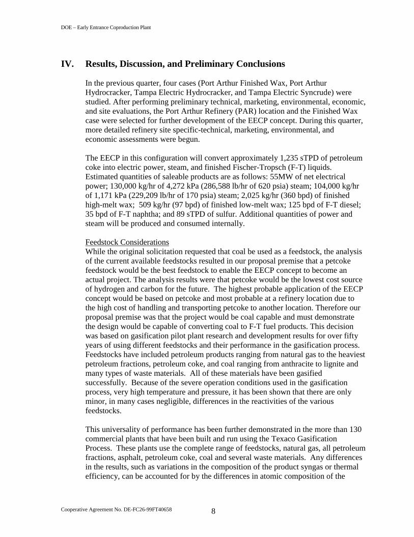
In the previous quarter, four cases (Port Arthur Finished Wax, Port ArthurHydrocracker, Tampa Electric Hydrocracker, and Tampa Electric Syncrude) werestudied. After performing preliminary technical, marketing, environmental, economic,and site evaluations, the Port Arthur Refinery (PAR) location and the Finished Waxcase were selected for further development of the EECP concept. During this quarter,more detailed refinery site specific-technical, marketing, environmental, andeconomic assessments were begun.
The EECP in this configuration will convert approximately 1,235 sTPD of petroleumcoke into electric power, steam, and finished Fischer-Tropsch (F-T) liquids.Estimated quantities of saleable products are as follows: 55MW of net electricalpower; 130,000 kg/hr of 4,272 kPa (286,588 lb/hr of 620 psia) steam; 104,000 kg/hrof 1,171 kPa (229,209 lb/hr of 170 psia) steam; 2,025 kg/hr (360 bpd) of finishedhigh-melt wax; 509 kg/hr (97 bpd) of finished low-melt wax; 125 bpd of F-T diesel;35 bpd of F-T naphtha; and 89 sTPD of sulfur. Additional quantities of power andsteam will be produced and consumed internally.
Feedstock ConsiderationsWhile the original solicitation requested that coal be used as a feedstock, the analysisof the current available feedstocks resulted in our proposal premise that a petcokefeedstock would be the best feedstock to enable the EECP concept to become anactual project. The analysis results were that petcoke would be the lowest cost sourceof hydrogen and carbon for the future. The highest probable application of the EECPconcept would be based on petcoke and most probable at a refinery location due tothe high cost of handling and transporting petcoke to another location. Therefore ourproposal premise was that the project would be coal capable and must demonstratethe design would be capable of converting coal to F-T fuel products. This decisionwas based on gasification pilot plant research and development results for over fiftyyears of using different feedstocks and their performance in the gasification process.Feedstocks have included petroleum products ranging from natural gas to the heaviestpetroleum fractions, petroleum coke, and coal ranging from anthracite to lignite andmany types of waste materials. All of these materials have been gasifiedsuccessfully. Because of the severe operation conditions used in the gasificationprocess, very high temperature and pressure, it has been shown that there are onlyminor, in many cases negligible, differences in the reactivities of the variousfeedstocks.
This universality of performance has been further demonstrated in the more than 130commercial plants that have been built and run using the Texaco GasificationProcess. These plants use the complete range of feedstocks, natural gas, all petroleumfractions, asphalt, petroleum coke, coal and several waste materials. Any differencesin the results, such as variations in the composition of the product syngas or thermalefficiency, can be accounted for by the differences in atomic composition of the

DOE – Early Entrance Coproduction Plant
Cooperative Agreement No. DE-FC26-99FT40658 9
feedstocks. Currently, new plants are designed based only on the chemicalcomposition of the feeds.
While this vast store of experience should demonstrate the validity of generalizinggasification performance across feedstocks, some interesting observations have beendeveloped in the cases of petroleum coke and coal. In many other process uses,where operating conditions are less severe, there are significant performancedifferences. In these cases, coal is generally more reactive than coke because of thedifferences in the molecular structures. Higher volatility of coal, due to the relativeease of its thermal cracking, is perhaps the most obvious difference and is the sourceof many of the process differences seen. These processes are generally reaction ratelimited at the lower temperatures and pressures used, and the volatiles generated inheating the coal react more rapidly than the solid portions of the material. But ingasification, reaction rates are extremely high, and primarily physical processes, heat,mass transfer and fluid mechanics determine the performance. When these processesare considered, coal and coke are quite similar and hence they perform the same inthe Texaco Gasification Process.
Description of the Proposed EECP FacilityPlease refer to Figure 1 (page 17) for a block flow diagram of the proposed facility.
Petroleum coke from the Port Arthur Refinery (PAR) Delayed Coking Unit (DCU) iscrushed, mixed with water, and pumped to the gasification section. This coke slurryis mixed with high-pressure oxygen from the Praxair air separation unit (ASU) and asmall quantity of high-pressure steam in a specially designed feed injector mountedon the gasifier. The resulting reactions take place very rapidly to produce synthesisgas, also known as syngas, that is composed primarily of hydrogen, carbon monoxide,water vapor, and carbon dioxide (CO2) with small amounts of hydrogen sulfide,methane, argon, nitrogen, and carbonyl sulfide. The raw syngas is scrubbed withwater to remove solids, cooled, then forwarded to the Acid Gas Removal Unit (AGR),where the stream is split. One portion of the stream is treated in the AGR to removeCO2 and H2S and then forwarded to the F-T synthesis unit. The other portion istreated in the AGR to remove the bulk of H2S with minimal CO2 removal and thenforwarded as fuel to the General Electric frame 6FA gas turbine. In the AGR solventregeneration step, nitrogen from the ASU is used as a stripping agent to release CO2.The resulting CO2 and nitrogen mixture is also sent to the gas turbine, which resultsin increased power production and reduced nitrogen oxides emissions. The bulk ofthe nitrogen is also sent to the gas turbine as a separate stream, where its mass flowalso helps increase power production and reduce nitrogen oxides emissions.
Overall, approximately 75% of the sweetened syngas is sent to the gas turbine as fuel.The remaining 25% is first passed through a zinc oxide bed arrangement to removethe remaining traces of sulfur and then forwarded to the F-T synthesis unit. In the F-Treactor, carbon monoxide and hydrogen react aided by an iron-based catalyst, to formmainly heavy straight-chain hydrocarbons. Since the reactions are highly exothermic,cooling coils are placed inside the reactor to remove the heat released by thereactions. Three hydrocarbon product streams; heavy F-T liquid, medium F-T liquid,and light F-T liquid are sent to the F-T product upgrading unit while F-T water, a

DOE – Early Entrance Coproduction Plant
Cooperative Agreement No. DE-FC26-99FT40658 10
reaction byproduct, is returned to the gasification unit and injected into the gasifier.The F-T tail gas and AGR offgas is sent to the gas turbine as fuel for additional powerproduction.
In the product upgrading section, the three F-T liquids are combined and processed asa single feed. The unit consists of a Bechtel Hy-Finishing™ reactor, productseparators, an atmospheric fractionator, naphtha stabilizer, a vacuum distillationtower, feed preheaters, hydrogen compression facilities, and product coolers. Thereaction is carried out at elevated pressure and temperature. A mixture of feedhydrocarbons and hydrogen-rich gas is fed to the top of the fixed bed reactor. In thepresence of a hydrotreating catalyst, hydrogen reacts slightly exothermally with thefeed to produce saturated hydrocarbons, water, and some hydrocracked light ends.The resulting four liquid product streams are naphtha, diesel, low melt wax, and highmelt wax. Each of these streams is sent to segregated product storage tanks. The waxtanks are insulated and equipped with steam coils to maintain the storage temperatureabove the wax melting point. All of the products leave the EECP facility via tanktruck. Transfer pumps and truck loading facilities are provided adjacent to the storagetanks.
The power block consists of a GE frame 6FA 60 hz heavy-duty gas turbine generatorand is integrated to a two-pressure level heat recovery steam generator and a non-condensing steam turbine generator. The system is designed to supply a portion of thecompressed air feed to the ASU, process steam to the refinery, and electrical powerfor export and use within the EECP facility. The gas turbine has a dual fuel supplysystem with natural gas as startup and backup fuel, and primary fuel as a mixture ofsyngas from the gasifier, off gas from the AGR unit, and tail gas from the F-Tsynthesis unit. Nitrogen gas for injection is supplied by the ASU for NOx abatement,power augmentation, and the fuel purge system. The combustion system design,including appropriate fuel nozzles, will require new design testing and validation. Theheat recovery steam generator is a two-pressure, non-reheat, natural circulation typewith horizontal gas flow and vertical fin tubes in all sections. It will be arranged witha high-pressure (HP) superheater, HP drum and evaporator, HP economizer,intermediate pressure (IP) superheater, IP drum and evaporator, and IP economizer.High pressure steam will be produced at 6,890 kPa (1,000 psia) and intermediatepressure steam at 1,275 kPa (185 psia).
The Praxair ASU is designed as a single train elevated pressure unit. Its primary dutyis to provide oxygen to the gasifier and Sulfur Recovery Unit (SRU), and all of theEECP’s requirements for nitrogen and instrument and compressed air. However, itcan also export surplus oxygen and nitrogen, when available, to PAR. As mentionedabove, ASU nitrogen product applications within EECP include its use as a strippingagent in the AGR, as a diluent in the gas turbine where its mass flow helps increasepower production and reduce nitrogen oxides emissions, and as an inert gas forpurging and inerting. The gas turbine, in return for diluent nitrogen suppliesapproximately 25% of the air feed to the ASU, which helps reduce the size of theASU’s compressor, hence oxygen supply cost.

DOE – Early Entrance Coproduction Plant
Cooperative Agreement No. DE-FC26-99FT40658 11
Acid gases from the AGR, as well as sour water stripper (SWS) offgas from thegasification unit, are first routed to knockout drums as they enter the Claus SRU.After entrained liquid is removed in these drums, the acid gas is preheated and fedalong with the SWS gas, oxygen, and air to a burner. H2S in the thermal reactor, aportion of which has been combusted to SO2, starts to recombine with the SO2 toform elemental sulfur. The reaction mixture then passes through a boiler to removeheat while generating steam. The sulfur-laden gas is sent to the first pass of theprimary sulfur condenser in which all sulfur is condensed. The gas is next preheatedbefore entering the first catalytic bed in which more H2S and SO2 are converted tosulfur. The sulfur is removed in the second pass of the primary sulfur condenser, andthe gas goes through a reheat, catalytic reaction, and condensing stage two moretimes before leaving the SRU as a tail gas. The molten sulfur from all fourcondensing stages is sent to the sulfur pit, from which product is transported offsiteby tank truck.
The tail gas from the SRU is preheated and reacted with hydrogen in a catalyticreactor to convert unreacted SO2 back to H2S. The reactor effluent is cooled whilegenerating steam before entering a quench tower for further cooling. A slip stream ofthe quench tower bottoms is filtered and sent along with the condensate from the SRUknockout drums to the SWS. H2S is removed from the quenched tail gas in anabsorber by lean methyldiethanolamine (MDEA) solvent from the AGR unit, and thetail gas from the absorber is thermally oxidized and vented to atmosphere. The richMDEA solvent returns to the AGR unit to be regenerated in the stripper.
The steam system of the EECP serves two main functions: (1) it serves as a mediumfor exporting a large amount of surplus heat from the EECP to PAR and (2) integratesthe heat balances between the individual process blocks within the EECP. The systemis designed to recover the maximum amount of heat from the EECP and to export it inthe form of 4,272kPa (620 psia) and 1,171 kPa (170 psia) superheated steam to therefinery. PAR will provide zeolite treated water which will be passed through amixed-bed polishing unit to remove final traces of contaminants and produce high-quality deaerator feed water. This water is first preheated by exchange with wasteheat streams available from the air separation unit and gasifier, then pumped to thedeaerator. Two low-pressure (LP) boiler feed water (BFW) pumps are used to deliverdeaerated water to the gasification section where low-grade heat is used to generate482 kPa (70 psia) saturated steam, which is used within the EECP facility. Otherportions of the low-pressure water are sent to the gasification unit and heat recoverysteam generator (HRSG) for production of 1,275 kPa (185 psia) saturated steam. Asignificant portion of this steam is consumed internally within the EECP facility,however approximately 103,997 kg/hr (229,209 lbs/hr) is superheated in the HRSGand exported to the refinery. The remaining portion of the low-pressure water ispassed through high-pressure boiler feedwater pumps and sent to the HRSG forproduction of 6,890 kPa (1,000 psia) saturated steam. A small portion of that steam isused in the gasifier and SRU, while the remainder is superheated in a HRSG coilbefore being let down to 4,272 kPa (620 psia) through a steam turbine. The steamturbine is used to drive a generator which recovers 2,827 kW (3,790 horsepower)from the letdown steam. Two intermediate-pressure (IP) BFW pumps are used to feeddeaerated water to both the 2,963 kPa (430 psia) and 4,272 kPa (620 psia) headers

DOE – Early Entrance Coproduction Plant
Cooperative Agreement No. DE-FC26-99FT40658 12
after heat exchange with a stream from the gasifier. A portion of the water also picksup heat from the F-T synthesis unit to produce 2,963 kPa (430 psia) saturated steamfor use within the EECP. The remainder is let down to the 1,275 kPa (185 psia)header. The remainder of the IP BFW is used to generate 4,272 kPa (620 psia)saturated steam which combines with the letdown from the steam turbine and isexported to PAR. Provisions are included for letting down steam from one header tothe next to facilitate control during start-ups or upset conditions.
A cooling water system is included in the EECP facility. The system consists of afreshwater cooling tower and basin. Motor driven cooling water pumps serve tocirculate cooling water between the cooling tower and various cooling waterexchangers within the EECP. A vendor maintained cooling water treatment unit isalso provided. Make-up water to the cooling tower is taken from PAR and coolingtower blowdown is sent to PAR for treatment.
A flare and associated piping and knockout drum are also provided to handle the fullflow of the gasifier in the event that a unit downstream of it should trip.
Firewater and service water systems are provided and connect to the much largerPAR facilities. Services such as sewer, potable water, and oily water systems are alsoconnected to the PAR facilities. In addition, costs for a control room, offices,laboratory, and maintenance shops have been included in the EECP capital costestimate.
The EECP is capable of operation without the F-T synthesis unit and F-T upgradingsection. In that case, all of the syngas will be used as fuel to the gas turbine. Thegasifier and ASU would then be operating at slightly reduced capacity, howeverpower and steam export to the refinery would be maintained.
Proposed EECP Facility Energy AuditAn overall energy assessment study was performed for the EECP facility. Pinchanalysis, a systematic approach based on thermodynamics, was used to determine theminimum energy requirements for the process subject to imposed constraints.Composite heating and cooling curves were developed and combined into acomposite curve by plotting the temperature with the enthalpy difference between thehot and cold composite curves. After the steam export was fixed, the opportunities forrecovering additional heat from the process were identified and the final heatexchange design was completed. The main objective of this study was to carry out anenergy audit of the process and identify opportunities to improve energy recovery ofthe proposed design. The analysis indicated the proposed process configurationexhibited a high degree of recoverable energy efficiency of about 92%. Thisefficiency value is considered high at this point in design. The detailed results of thestudy will be included in the Concept Report.
Proposed EECP Facility Thermal EfficiencyOn a gross heating value basis, the proposed EECP thermal efficiency has beenestimated at 66.5%. This calculation is based on processing 1,235 short tons per dayof petroleum coke to produce saleable products of: 55MW of net electrical power;
DOE – Early Entrance Coproduction Plant
Cooperative Agreement No. DE-FC26-99FT40658 13
130,000 kg/hr of 4,272 kPa (286,588 lb/hr of 620 psia) steam; 104,000 kg/hr of 1,171kPa (229,209 lb/hr of 170 psia) steam; 2,025 kg/hr (360 bpd) of finished high-meltwax; 509 kg/hr (97 bpd) of finished low-melt wax; 125 bpd of F-T diesel; 35 bpd ofF-T naphtha; and 89 short tons per day of sulfur.
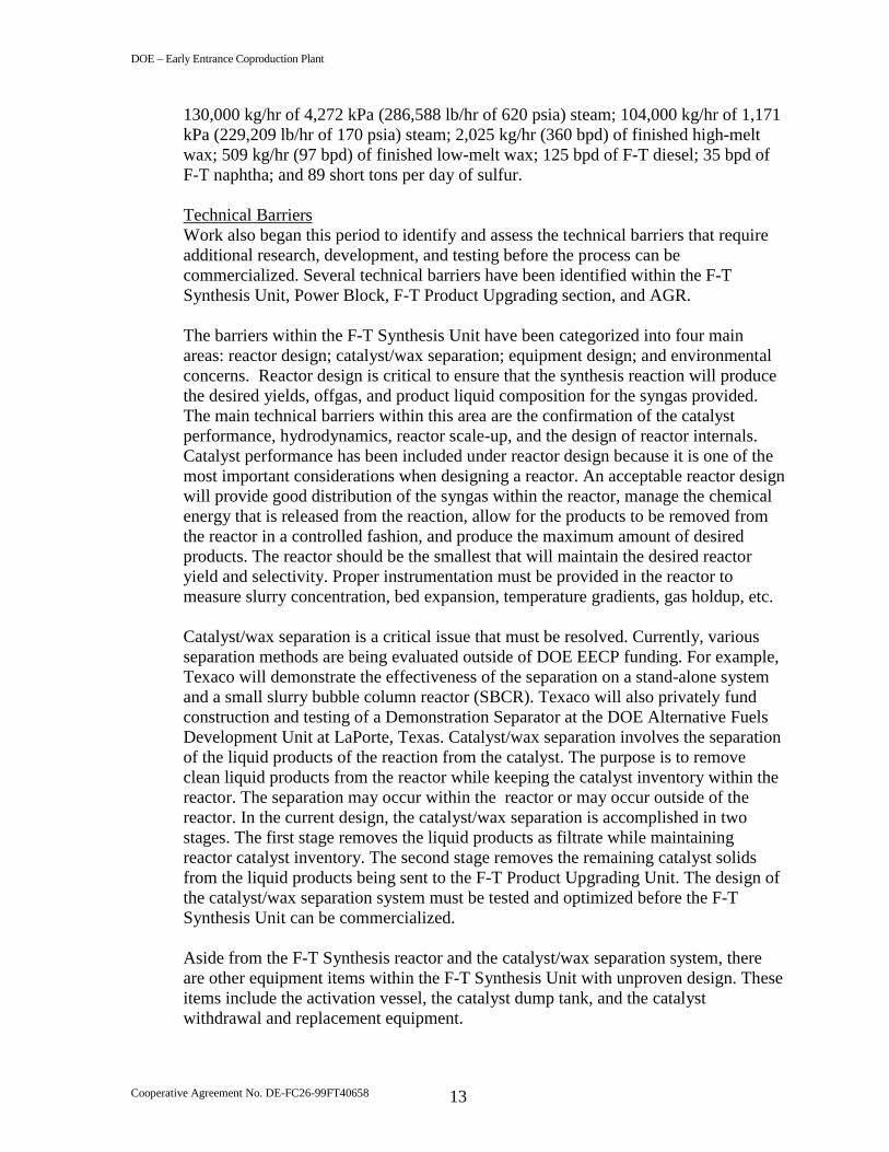
Technical BarriersWork also began this period to identify and assess the technical barriers that requireadditional research, development, and testing before the process can becommercialized. Several technical barriers have been identified within the F-TSynthesis Unit, Power Block, F-T Product Upgrading section, and AGR.
The barriers within the F-T Synthesis Unit have been categorized into four mainareas: reactor design; catalyst/wax separation; equipment design; and environmentalconcerns. Reactor design is critical to ensure that the synthesis reaction will producethe desired yields, offgas, and product liquid composition for the syngas provided.The main technical barriers within this area are the confirmation of the catalystperformance, hydrodynamics, reactor scale-up, and the design of reactor internals.Catalyst performance has been included under reactor design because it is one of themost important considerations when designing a reactor. An acceptable reactor designwill provide good distribution of the syngas within the reactor, manage the chemicalenergy that is released from the reaction, allow for the products to be removed fromthe reactor in a controlled fashion, and produce the maximum amount of desiredproducts. The reactor should be the smallest that will maintain the desired reactoryield and selectivity. Proper instrumentation must be provided in the reactor tomeasure slurry concentration, bed expansion, temperature gradients, gas holdup, etc.
Catalyst/wax separation is a critical issue that must be resolved. Currently, variousseparation methods are being evaluated outside of DOE EECP funding. For example,Texaco will demonstrate the effectiveness of the separation on a stand-alone systemand a small slurry bubble column reactor (SBCR). Texaco will also privately fundconstruction and testing of a Demonstration Separator at the DOE Alternative FuelsDevelopment Unit at LaPorte, Texas. Catalyst/wax separation involves the separationof the liquid products of the reaction from the catalyst. The purpose is to removeclean liquid products from the reactor while keeping the catalyst inventory within thereactor. The separation may occur within the reactor or may occur outside of thereactor. In the current design, the catalyst/wax separation is accomplished in twostages. The first stage removes the liquid products as filtrate while maintainingreactor catalyst inventory. The second stage removes the remaining catalyst solidsfrom the liquid products being sent to the F-T Product Upgrading Unit. The design ofthe catalyst/wax separation system must be tested and optimized before the F-TSynthesis Unit can be commercialized.
Aside from the F-T Synthesis reactor and the catalyst/wax separation system, thereare other equipment items within the F-T Synthesis Unit with unproven design. Theseitems include the activation vessel, the catalyst dump tank, and the catalystwithdrawal and replacement equipment.

DOE – Early Entrance Coproduction Plant
Cooperative Agreement No. DE-FC26-99FT40658 14
In addition to the equipment design issues, there are some process design andenvironmental issues that need resolution. These include the disposal of F-T synthesiscatalyst and the use of F-T water in the gasification section. Testing will be requiredto confirm that the assumed methods are technically feasible.
The GE multi-shaft combined cycle STAG (steam and gas) 106FA systemconfiguration designed for the EECP plant uses commercially available equipmentexcept for the gas turbine combustion system. The GE 6FA gas turbine has beensuccessfully tested for operation on syngas produced in Texaco gasifiers from avariety of feedstocks such as coal, coke, vacuum residue, etc. For the EECP proposed,part of the syngas from the Texaco gasification unit, after getting treated in the AGR,will be sent to the F-T Synthesis Unit for conversion into liquid products. The tail gasfrom the F-T Synthesis Unit consists of uncondensed reactor products along withunreacted F-T feed gas. The thermal energy content of the F-T tail gas is lower thanthe syngas. There is no operating experience with the burning of this tail gas in thecommercial combustion turbine. The percentage of F-T tail gas that can be burnedalong with the mixture of Texaco gasifier syngas and offgas from the AGR is notknown. Moreover, the gas turbine combustor required in this design will also have airextraction for the ASU and nitrogen injection near the reaction zone for NOx emissioncontrol. The gas turbine combustion system will need to be designed and testedbefore it can be offered for commercial operation.
With regard to technical barriers for F-T Product Upgrading, the Bechtel Wax Hy-Finishing™ technology has not yet been applied specifically to the hydrogenation ofF-T liquids, although the concept of processing feeds of this composition iscommercially proven. Summarily, the barriers to full confidence in the processtechnology to produce finished wax include: operating conditions of temperature,pressure, hydrogen to hydrocarbon ratio; deactivation rate of the process catalyst;separation of light hydrocarbon byproducts produced during the process; andseparation of the finished wax into narrow boiling and viscosity ranges withoutthermal degradation.
The primary technical risk with the AGR is the uncertainty of commercial trayefficiencies at medium pressure in stripping a rich amine with nitrogen at mediumpressures. Error in this regard has a potential double negative impact that could resultin less CO2 to the gas turbine and more CO2 to the SRU. Other potential risks includetrace or acidic contaminants in the syngas that may cause amine degradation and/orcorrosion problems and trace oxygen in the stripping nitrogen that may causeformation of heat stable salts and other degradation problems. These risks are judgedrelatively minimal since they could be addressed by design issues and/or availabletechnologies that would mitigate or eliminate them.
In Phase I, solutions have been assumed for all of the above technical barriers. DuringPhase II, research, development, and testing will be performed to confirm and todevelop solutions to the technical barriers that have been identified. Some of the workwill be done within the scope of Phase II of the EECP and some will be performedoutside the scope of the EECP.
DOE – Early Entrance Coproduction Plant
Cooperative Agreement No. DE-FC26-99FT40658 15
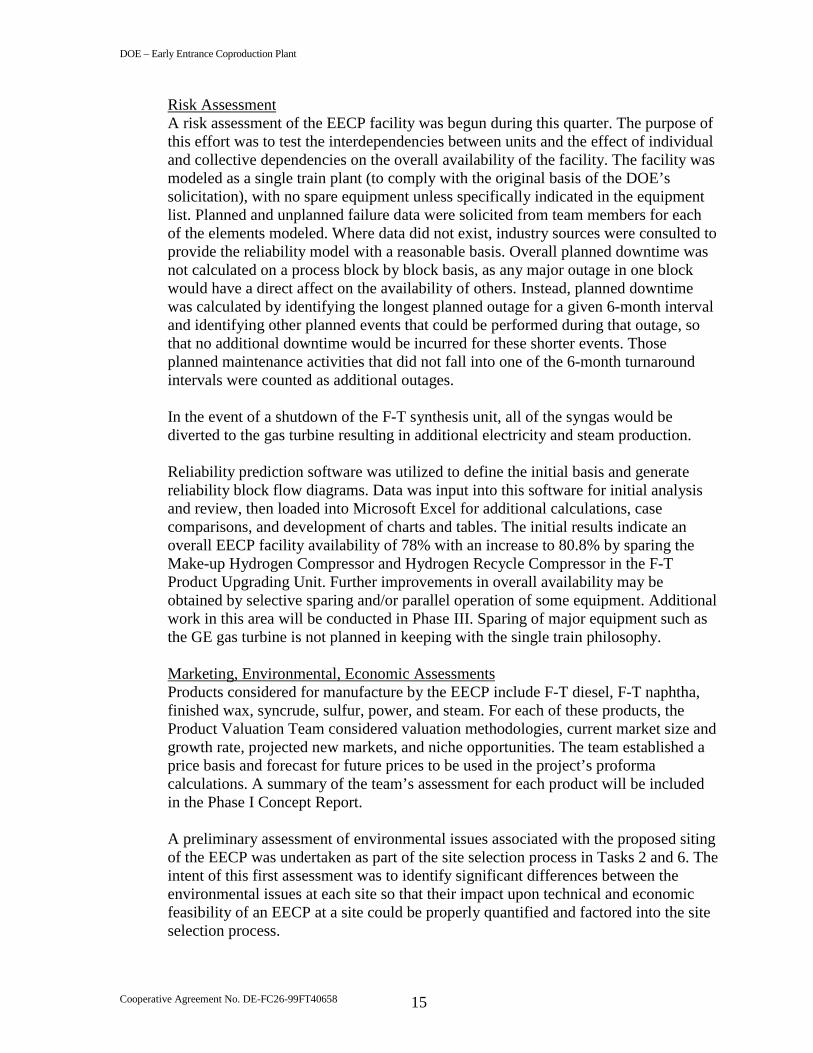
Risk AssessmentA risk assessment of the EECP facility was begun during this quarter. The purpose ofthis effort was to test the interdependencies between units and the effect of individualand collective dependencies on the overall availability of the facility. The facility wasmodeled as a single train plant (to comply with the original basis of the DOE’ssolicitation), with no spare equipment unless specifically indicated in the equipmentlist. Planned and unplanned failure data were solicited from team members for eachof the elements modeled. Where data did not exist, industry sources were consulted toprovide the reliability model with a reasonable basis. Overall planned downtime wasnot calculated on a process block by block basis, as any major outage in one blockwould have a direct affect on the availability of others. Instead, planned downtimewas calculated by identifying the longest planned outage for a given 6-month intervaland identifying other planned events that could be performed during that outage, sothat no additional downtime would be incurred for these shorter events. Thoseplanned maintenance activities that did not fall into one of the 6-month turnaroundintervals were counted as additional outages.
In the event of a shutdown of the F-T synthesis unit, all of the syngas would bediverted to the gas turbine resulting in additional electricity and steam production.
Reliability prediction software was utilized to define the initial basis and generatereliability block flow diagrams. Data was input into this software for initial analysisand review, then loaded into Microsoft Excel for additional calculations, casecomparisons, and development of charts and tables. The initial results indicate anoverall EECP facility availability of 78% with an increase to 80.8% by sparing theMake-up Hydrogen Compressor and Hydrogen Recycle Compressor in the F-TProduct Upgrading Unit. Further improvements in overall availability may beobtained by selective sparing and/or parallel operation of some equipment. Additionalwork in this area will be conducted in Phase III. Sparing of major equipment such asthe GE gas turbine is not planned in keeping with the single train philosophy.
Marketing, Environmental, Economic AssessmentsProducts considered for manufacture by the EECP include F-T diesel, F-T naphtha,finished wax, syncrude, sulfur, power, and steam. For each of these products, theProduct Valuation Team considered valuation methodologies, current market size andgrowth rate, projected new markets, and niche opportunities. The team established aprice basis and forecast for future prices to be used in the project’s proformacalculations. A summary of the team’s assessment for each product will be includedin the Phase I Concept Report.
A preliminary assessment of environmental issues associated with the proposed sitingof the EECP was undertaken as part of the site selection process in Tasks 2 and 6. Theintent of this first assessment was to identify significant differences between theenvironmental issues at each site so that their impact upon technical and economicfeasibility of an EECP at a site could be properly quantified and factored into the siteselection process.

DOE – Early Entrance Coproduction Plant
Cooperative Agreement No. DE-FC26-99FT40658 16
After selection of the Port Arthur Refinery site and more improvement of theintegration of the EECP with the host site, the environmental issues will bereassessed during the next quarter and will be reported under Task 7 of the ConceptReport. The work in this task consists of identifying the relevant environmentalrequirements that would be imposed on an EECP implementation at Port Arthur, andof quantifying the expected emissions from an EECP. Several opportunities forintegration of the environmental control technologies with the host site exist. Thisintegration will result in lower costs without compromising environmental concerns.The overall work accomplished in Task 7 will provide a strong basis for furtherenvironmental evaluations as part of Phase III of the project and will be documentedin the Concept Report.
The economics of the EECP will be evaluated at two points during Phase I: firstduring the site selection process (Tasks 2 and 6) and second after the facilityconfiguration and capital and operating costs estimates are completed for the PortArthur Refinery site. The cost estimates will be completed in the fourth quarter, 2000and then the economics determined by use of an in-house developed economic model.This model provides the ability to change various input parameters and note theiraffect on several financial return calculations. Details of the various runs, includingcapital and operating cost estimates, along with explanations of their basis, will beincluded in the Concept Report.

DOE – Early Entrance Coproduction Plant
Cooperative Agreement No. DE-FC26-99FT40658 17
Figure 1Overall Block Flow Diagram
H 2 O toG a sific a tio n~
H 2 O from F-TSy n the sis
Sy nga s fue l
20 00 -8 00 0G asifica tio n
90 00A cid G asR em ova l
10 00 0F -TSy n thes is
12 00 0G as T urb ine
15 00 0SR U /T G T U
11 00 0F -TP ro du ctU p grad e
FTT ail G asSy nthe sis
G as
C O 2 ,N 2
A c id G as
S y nga s F eed
O 2
12 75 k Pa(18 0 )p sia S te am
Pe tro leu mC ok e
Su lfur
F Tprod ucts(N ote 1)
N 2
Po w er(55 M W N e t)
10 00A S U
Pu rc hasedM ak e u pH y droge n
N GSta nd-byFu el 12 00 0
H ea t R ec /S te amG en era tion
47 72k P a(620 psia)S te am
N a phth a
D iesel
11 71 k Pa(170 psia) S te am
G reyW aterB low dow n
O 2O ff ga s
68 90k Pa(100 0psia) S team
4 2 77k Pa(620 psia) S te am
L M W ax
H M W ax(N ote 2)
M ak e-upW ater
~
H 2 Purge
Flu e g as
E xtrac tion A ir
N 2 E xpo rtO 2 E xpo rt
A ir
F in es to sla g
A ir
Kellogg Brown & Root, Inc.A Halliburton Company
Engineering services by HalliburtonTechnical Services, Inc.
T H I S D O C U M E N T C O N T A I N S I N F O R M AT I O N W H I C H I SPROPRIETARY TO KELLOGG BROWN & ROOT. THIS INFORMATIONIS TO BE HELD IN CONFIDENCE. NO DISCLOSURE, REPRODUCTIONOR OTHER USE OF THIS DOCUMENT IS TO BE MADE WITHOUT THEPRIOR WRITTEN CONSENT OF KELLOGG BROWN & ROOT.
APPROVED
CHECKEDDESIGNER
DRAWN JSA REV.DATE 10/10/00
DATEDATEDATE
DOE AWARD NUMBER: DE-FC-99FT40658
DOE EARLY ENTRANCE COPRODUCTION PLANT
OVERALL BLOCK FLOW DIAGRAM
0SUBTRACTOR PROJECT NO: 9202TASK NO: 4.1.2DRAWING NO: KBR-P-BFD-0001
PORT ARTHUR REFINERYNOTES:
1. Includes Light, Medium and Heavy FT Liquid product streams2. LM = Low Melt HM = High Melt

DOE – Early Entrance Coproduction Plant
Cooperative Agreement No. DE-FC26-99FT40658 18
V. List of Major Activities Accomplished in 3Q2000
The following list is provided as a quick reference for the work performed duringthis reporting period:
• Completed process basis of design for Port Arthur Refinery Finished Wax(PARFW) case
• Contracted with Bechtel for F-T Product Upgrading work• Completed technical assessment of subsystems• Continued preparation of subsystem design basis• Began risk assessment of subsystems• Began cost estimating activities for PARFW case• Began updating market, environmental, and economic assessments for
PARFW case• Began RD&T planning and preparation of the RD&T Report• Began preparation of the Phase I Concept Report• Issued 2Q2000 quarterly report for comments
DOE- Early Entrance Coproduction Plant
Cooperative Agreement No. DE-FC26-99FT40658 19
VI. List of Planned Activities for 4Q2000
The following list is provided as a quick reference for the work planned for theupcoming quarter:
• Complete all process design for PARFW case• Complete risk assessment of subsystems• Complete cost estimating activities for PARFW case• Complete marketing, environmental, and economic assessments for PARFW
case• Issue 2Q2000 Final Quarterly Report• Issue 3Q2000 Quarterly Report for comments• Complete and submit RD&T Plan to DOE for comments• Complete and submit Phase I Concept Report to DOE for comments• Complete and submit Preliminary Financing Plan to DOE for comments

DOE- Early Entrance Coproduction Plant
Cooperative Agreement No. DE-FC26-99FT40658 20
VII. Graphs
The following three graphs depict the financial status and progress of Phase Iactivities. The graphs are shown on the following three pages:
Planned vs. Actual Total Expenditures .............................................................. 21Planned vs. Actual DOE Expenditures .............................................................. 22Total Project Percent Complete.......................................................................... 23

DOE- Early Entrance Coproduction Plant
Cooperative Agreement No. DE-FC26-99FT40658 21
Early Entrance Coproduction PlantPhase I - Total Expenditures
0
500,000
1,000,000
1,500,000
2,000,000
2,500,000
3,000,000
Planned 0 262,896 859,687 1,701,482 2,173,750 2,802,782 2,808,813
Actual 0 105,434 384,911 752,706 1,287,786
3Q 99 4Q 99 1Q 00 2Q 00 3Q 00 4Q 00 1Q 01

DOE- Early Entrance Coproduction Plant
Cooperative Agreement No. DE-FC26-99FT40658 22
Early Entrance Coproduction PlantPhase I - DOE Expenditures
0
500,000
1,000,000
1,500,000
2,000,000
2,500,000
3,000,000
Dol
lars
Planned 0 210,316 687,750 1,361,185 1,739,000 2,242,225 2,247,050Actual 0 84,347 307,928 602,165 1,030,229
3Q 99 4Q 99 1Q 00 2Q 00 3Q 00 4Q 00 1Q 01

DOE- Early Entrance Coproduction Plant
Cooperative Agreement No. DE-FC26-99FT40658 23
Early Entrance Coproduction PlantPhase I - Total Percent Complete
0
20
40
60
80
100
Planned 0 10 30 66 92 99 100
Actual 0 8 24 40 81
Forecast 81 95 100
3Q 99 4Q 99 1Q 00 2Q 00 3Q 00 4Q 00 1Q 01

DOE- Early Entrance Coproduction Plant
Cooperative Agreement No. DE-FC26-99FT40658 24
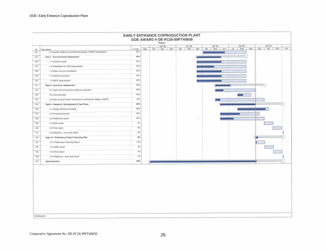
VIII. Schedule
The following two pages depict the updated Phase I project schedule and showpercent complete by task as of the end of 3Q2000. For a description of the workinvolved in each task, refer to the Cooperative Agreement. This schedule wasprepared using MS Project 98 software.

DOE- Early Entrance Coproduction Plant
Cooperative Agreement No. DE-FC26-99FT40658 25
DOE- Early Entrance Coproduction Plant
Cooperative Agreement No. DE-FC26-99FT40658 26