Embed Size (px)
Citation preview
Technical Data
E1 Plus Overload Relay SpecificationsBulletin Numbers 193, 592
Summary of Changes
This publication contains new and updated information as indicated in the following table.
Topic PageSummary of Changes 1Product Overview 2Features 3Catalog Number Explanation 5Product Selection 6Accessories 7Specifications 11Approximate Dimensions 16
Topic Pages
Corrected Cat. Nos. for 100-E-compatible 3-phase devices 6
E1 Plus Overload Relay Specifications
Product Overview
Standards Compliance and Certifications
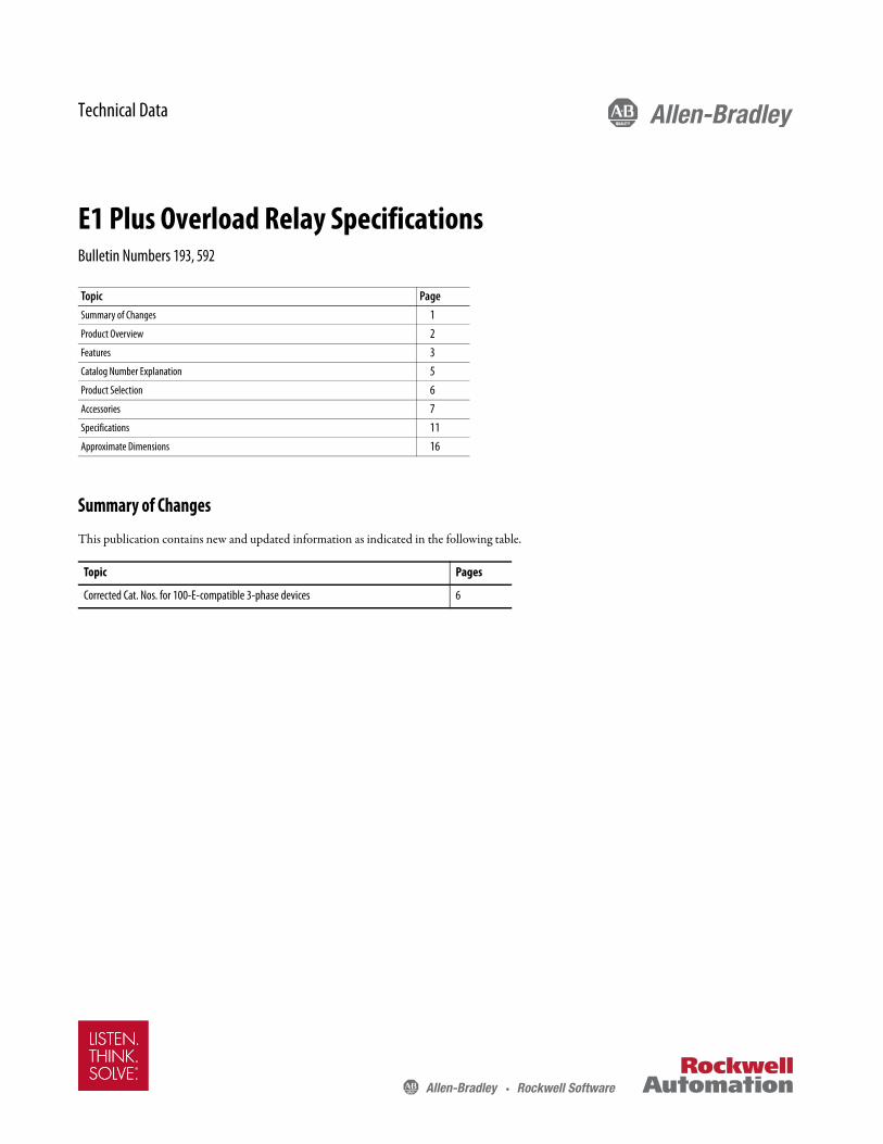
Bulletin 193-ED 193/592-EE
Type E1 Plus™ Electronic Overload Relay E1 Plus Electronic Overload Relay
Rated Current (Range) 0.1…45 A 0.1…800 A
NEMA Operating Voltage, Nominal — 600V
IEC Operating Voltage, Nominal 690V 690/1000V
Overload Type Electronic Overload Electronic Overload
Trip Class (Fixed) 10 —
Trip Class (Adjustable) — 10, 15, 20, 30
Ambient Temperature CompensatedReset Type Manual Only Automatic and Manual
Adjustment Range 5:1 5:1
Phase Loss 3 s 3 s
Ground (Earth) Fault — Optional
Overcurrent (Jam) Detection — Optional
Stall Detection — —
Underload Detection — —
Current Imbalance — —
PTC Thermistor Monitoring — Optional
Warning Settings — —
N.C. Trip ContactN.O. Alarm ContactNo. of Outputs — —
No. of Inputs — —
ODVA (DeviceNet) Conformance — Optional
Variable Frequency Drive (VFD) Compatible — —
Standards Compliance CertificationsEN 60947-4-1 c-UL-us Listed
EN 60947-5-1 CE Marked
CSA 22.2, No. 14 RCM
UL 508 C-Tick
2 Rockwell Automation Publication 193-TD011D-EN-P - April 2019
E1 Plus Overload Relay Specifications
Features
Accurate, Reliable Performance
Current measurement-based protection
While electromechanical overload relays pass motor current through heating elements to provide an indirect simulation of motor heating, the E1 Plus Overload Relay directly measures motor current. Current measurement-based overload protection more accurately models a motor’s thermal condition. Furthermore, ambient temperature does not impact the performance of current measurement-based designs over the specified temperature operating range.
Electronic design
Thermal modeling is performed electronically with precision solid-state components, where at the heart of the E1 Plus Overload Relay is an application-specific integrated circuit (ASIC). The ASIC continually processes motor current data to accurately maintain the time-current status of the motor thermal capacity utilization value.
Thermal memory
A thermal memory circuit allows the E1 Plus Overload Relay to model the heating and cooling effects of motor on and off periods. This achieves accurate protection for both hot and cold motors.
Enhanced phase loss protection
A separate phase loss detection circuit that is incorporated into the E1 Plus Overload Relay allows it to respond quickly to phase loss conditions; typical reaction time is 3 seconds.
Easy to Select and Apply
Straightforward installation
The self-powered design means that the E1 Plus Overload Relay installs in the same manner as traditional overload relays. Set up the device by dialing the setting potentiometer to the motor FLA rating. The low energy consumption of the electronic design minimizes temperature rise issues inside control cabinets.
Wide adjustment range
A wide 5:1 adjustment range requires half as many catalog numbers as the bimetallic alternative to cover the same current range. This helps to reduce inventory carrying costs and affords greater installation flexibility for dual-voltage machines. Evenly spaced setting tick marks enhance the ease of installation setup.
Rugged Construction
Over-molded power connections
The unique line-side over-molded power connections make for a sturdy two-component starter assembly that is unmatched in the industry. The pre-formed power connections allow easy starter assembly—every time.
Current transformers
The current transformers are secured separately in the overload housing to deliver the greatest degree of resistance to shock and vibration conditions. Varnished laminations deliver consistent performance and provide additional protection against corrosion.
Latching relay
The robust design of the bi-polar latching relay provides reliable trip and reset performance for the most demanding of applications. The self-enclosed relay offers additional environmental protection for use in industrial applications.
Application Flexibility
Isolated Contacts
The isolated contact configuration allows the N.C. and N.O. contacts to be applied in circuits operating at different voltage levels and without polarity restrictions. The B600 contact rating affords application in circuits that are rated to 600V.
DIP Switch settings
193-EE devices offer DIP Switch settings to select the trip class (10, 15, 20 or 30) and the reset mode (manual or automatic), making these devices versatile.
Pass-thru Option
The E1 Plus Pass-thru consumes 48% less panel space than a standard E1 Plus mounted in a panel mount adapter. The design provides an integrated DIN Rail mount and panel mounting holes and is intended for the following applications: DIN Rail and Panel Mount Applications, Bulletin 100-K mini contactor, external current transformers, and for use with non Allen-Bradley contactors. The E1 Plus Pass-thru Electronic Overload Relay provides the same expandable protection and communication capabilities as a standard E1 Plus, but does not require a separate panel mount adapter, which saves money and valuable panel space.
Rockwell Automation Publication 193-TD011D-EN-P - April 2019 3
E1 Plus Overload Relay Specifications
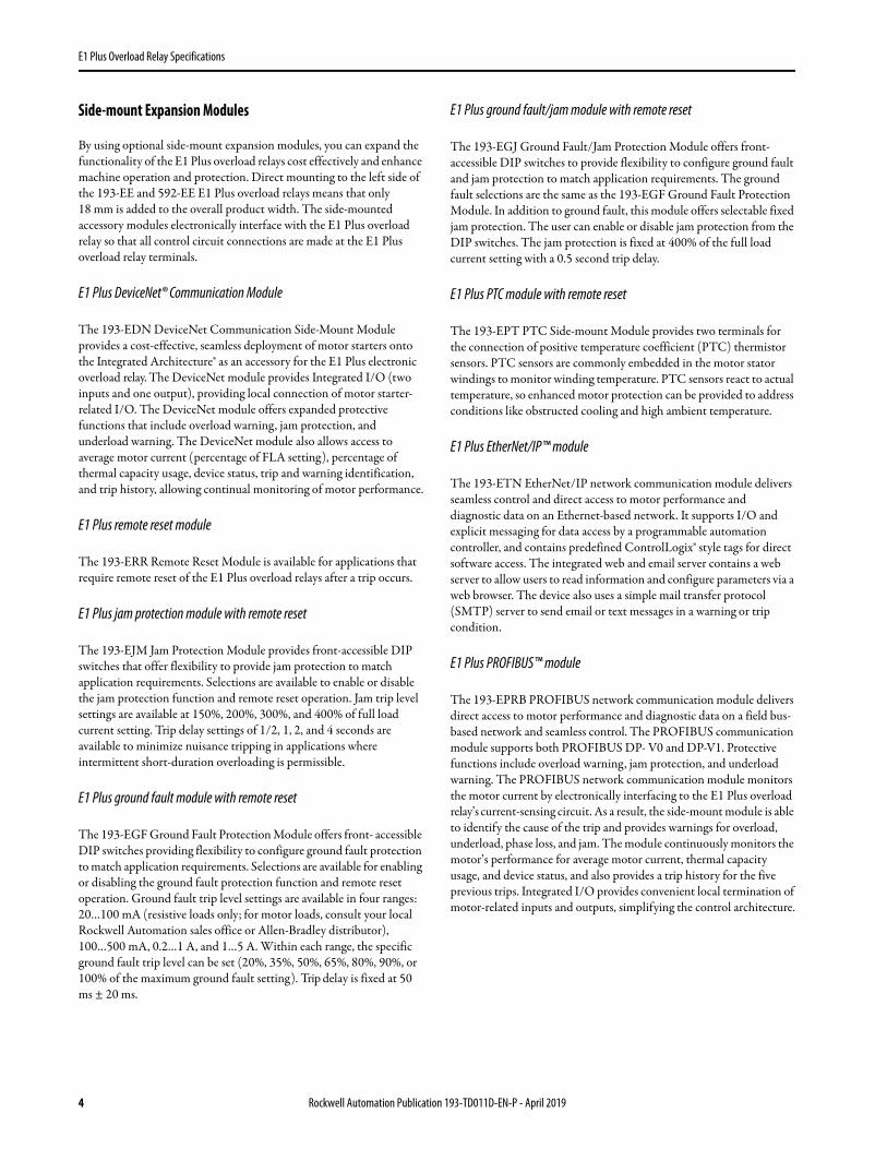
Side-mount Expansion Modules
By using optional side-mount expansion modules, you can expand the functionality of the E1 Plus overload relays cost effectively and enhance machine operation and protection. Direct mounting to the left side of the 193-EE and 592-EE E1 Plus overload relays means that only 18 mm is added to the overall product width. The side-mounted accessory modules electronically interface with the E1 Plus overload relay so that all control circuit connections are made at the E1 Plus overload relay terminals.
E1 Plus DeviceNet® Communication Module
The 193-EDN DeviceNet Communication Side-Mount Module provides a cost-effective, seamless deployment of motor starters onto the Integrated Architecture® as an accessory for the E1 Plus electronic overload relay. The DeviceNet module provides Integrated I/O (two inputs and one output), providing local connection of motor starter-related I/O. The DeviceNet module offers expanded protective functions that include overload warning, jam protection, and underload warning. The DeviceNet module also allows access to average motor current (percentage of FLA setting), percentage of thermal capacity usage, device status, trip and warning identification, and trip history, allowing continual monitoring of motor performance.
E1 Plus remote reset module
The 193-ERR Remote Reset Module is available for applications that require remote reset of the E1 Plus overload relays after a trip occurs.
E1 Plus jam protection module with remote reset
The 193-EJM Jam Protection Module provides front-accessible DIP switches that offer flexibility to provide jam protection to match application requirements. Selections are available to enable or disable the jam protection function and remote reset operation. Jam trip level settings are available at 150%, 200%, 300%, and 400% of full load current setting. Trip delay settings of 1/2, 1, 2, and 4 seconds are available to minimize nuisance tripping in applications where intermittent short-duration overloading is permissible.
E1 Plus ground fault module with remote reset
The 193-EGF Ground Fault Protection Module offers front- accessible DIP switches providing flexibility to configure ground fault protection to match application requirements. Selections are available for enabling or disabling the ground fault protection function and remote reset operation. Ground fault trip level settings are available in four ranges: 20…100 mA (resistive loads only; for motor loads, consult your local Rockwell Automation sales office or Allen-Bradley distributor), 100…500 mA, 0.2…1 A, and 1…5 A. Within each range, the specific ground fault trip level can be set (20%, 35%, 50%, 65%, 80%, 90%, or 100% of the maximum ground fault setting). Trip delay is fixed at 50 ms ± 20 ms.
E1 Plus ground fault/jam module with remote reset
The 193-EGJ Ground Fault/Jam Protection Module offers front- accessible DIP switches to provide flexibility to configure ground fault and jam protection to match application requirements. The ground fault selections are the same as the 193-EGF Ground Fault Protection Module. In addition to ground fault, this module offers selectable fixed jam protection. The user can enable or disable jam protection from the DIP switches. The jam protection is fixed at 400% of the full load current setting with a 0.5 second trip delay.
E1 Plus PTC module with remote reset
The 193-EPT PTC Side-mount Module provides two terminals for the connection of positive temperature coefficient (PTC) thermistor sensors. PTC sensors are commonly embedded in the motor stator windings to monitor winding temperature. PTC sensors react to actual temperature, so enhanced motor protection can be provided to address conditions like obstructed cooling and high ambient temperature.
E1 Plus EtherNet/IP™ module
The 193-ETN EtherNet/IP network communication module delivers seamless control and direct access to motor performance and diagnostic data on an Ethernet-based network. It supports I/O and explicit messaging for data access by a programmable automation controller, and contains predefined ControlLogix® style tags for direct software access. The integrated web and email server contains a web server to allow users to read information and configure parameters via a web browser. The device also uses a simple mail transfer protocol (SMTP) server to send email or text messages in a warning or trip condition.
E1 Plus PROFIBUS™ module
The 193-EPRB PROFIBUS network communication module delivers direct access to motor performance and diagnostic data on a field bus-based network and seamless control. The PROFIBUS communication module supports both PROFIBUS DP- V0 and DP-V1. Protective functions include overload warning, jam protection, and underload warning. The PROFIBUS network communication module monitors the motor current by electronically interfacing to the E1 Plus overload relay’s current-sensing circuit. As a result, the side-mount module is able to identify the cause of the trip and provides warnings for overload, underload, phase loss, and jam. The module continuously monitors the motor’s performance for average motor current, thermal capacity usage, and device status, and also provides a trip history for the five previous trips. Integrated I/O provides convenient local termination of motor-related inputs and outputs, simplifying the control architecture.
4 Rockwell Automation Publication 193-TD011D-EN-P - April 2019
E1 Plus Overload Relay Specifications
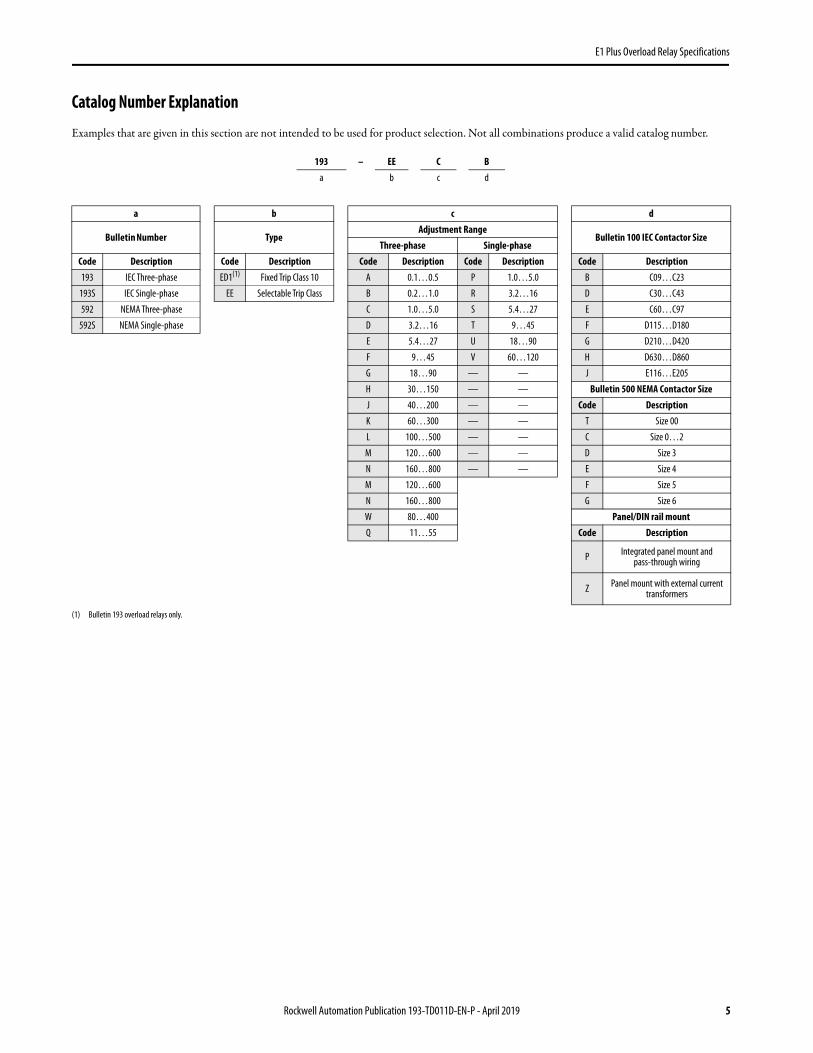
Catalog Number Explanation
Examples that are given in this section are not intended to be used for product selection. Not all combinations produce a valid catalog number.
193 – EE C Ba b c d
a b c d
Bulletin Number TypeAdjustment Range
Bulletin 100 IEC Contactor SizeThree-phase Single-phase
Code Description Code Description Code Description Code Description Code Description193 IEC Three-phase ED1(1)
(1) Bulletin 193 overload relays only.
Fixed Trip Class 10 A 0.1…0.5 P 1.0…5.0 B C09…C23
193S IEC Single-phase EE Selectable Trip Class B 0.2…1.0 R 3.2…16 D C30…C43
592 NEMA Three-phase C 1.0…5.0 S 5.4…27 E C60…C97
592S NEMA Single-phase D 3.2…16 T 9…45 F D115…D180
E 5.4…27 U 18…90 G D210…D420
F 9…45 V 60…120 H D630…D860
G 18…90 — — J E116…E205
H 30…150 — — Bulletin 500 NEMA Contactor SizeJ 40…200 — — Code DescriptionK 60…300 — — T Size 00
L 100…500 — — C Size 0…2
M 120…600 — — D Size 3
N 160…800 — — E Size 4
M 120…600 F Size 5
N 160…800 G Size 6
W 80…400 Panel/DIN rail mountQ 11…55 Code Description
P Integrated panel mount and pass-through wiring
Z Panel mount with external current transformers
Rockwell Automation Publication 193-TD011D-EN-P - April 2019 5
E1 Plus Overload Relay Specifications
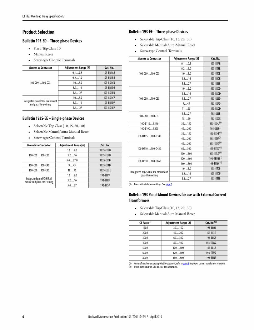
Product SelectionBulletin 193-ED – Three-phase Devices
• Fixed Trip Class 10• Manual Reset• Screw-type Control Terminals
Bulletin 193S-EE – Single-phase Devices• Selectable Trip Class (10, 15, 20, 30)• Selectable Manual/Auto-Manual Reset• Screw-type Control Terminals
Bulletin 193-EE – Three-phase Devices• Selectable Trip Class (10, 15, 20, 30)• Selectable Manual/Auto-Manual Reset• Screw-type Control Terminals
Bulletin 193 Panel Mount Devices for use with External Current Transformers
• Selectable Trip Class (10, 15, 20, 30)• Selectable Manual/Auto Manual Reset
Mounts to Contactor Adjustment Range [A] Cat. No.
100-C09…100-C23
0.1…0.5 193-ED1AB
0.2…1.0 193-ED1BB
1.0…5.0 193-ED1CB
3.2…16 193-ED1DB
5.4…27 193-ED1EB
Integrated panel/DIN Rail mount and pass-thru wiring
1.0…5.0 193-ED1CP
3.2…16 193-ED1DP
5.4…27 193-ED1EP
Mounts to Contactor Adjustment Range [A] Cat. No.
100-C09…100-C23
1.0…5.0 193S-EEPB
3.2…16 193S-EERB
5.4…27.0 193S-EESB
100-C30…100-C43 9…45 193S-EETD
100-C60…100-C85 18…90 193S-EEUE
Integrated panel/DIN Rail mount and pass-thru wiring
1.0…5.0 193-EEPP
3.2…16 193-EERP
5.4…27 193-EESP
Mounts to Contactor Adjustment Range [A] Cat. No.
100-C09…100-C23
0.1…0.5 193-EEAB
0.2…1.0 193-EEBB
1.0…5.0 193-EECB
3.2…16 193-EEDB
5.4…27 193-EEEB
100-C30…100-C55
1.0…5.0 193-EECD
3.2…16 193-EEDD
5.4…27 193-EEED
9…45 193-EEFD
11…55 193-EEQD
100-C60…100-C975.4…27 193-EEEE
18…90 193-EEGE
100-E116…E146 30…150 193-EEHJ(1)
(1) Does not include terminal lugs. See page 7.
100-E190…E205 40…200 193-EEJJ(1)
100-D115…100-D18030…150 193-EEHF(1)
40…200 193-EEJF(1)
100-D210…100-D420
40…200 193-EEJG(1)
60…300 193-EEKG(1)
100…500 193-EELG(1)
100-D630…100-D860120…600 193-EEMH(1)
160…800 193-EENH(1)
Integrated panel/DIN Rail mount and pass-thru wiring
1.0…5.0 193-EECP
3.2…16 193-EEDP
5.4…27 193-EEEP
CT Ratio(1)
(1) Current Transformers are supplied by customer, refer to page 8 for proper current transformer selection.
Adjustment Range [A] Cat. No.(2)
(2) Order panel adapter, Cat. No. 193-EPB separately.
150:5 30…150 193-EEHZ
200:5 40…200 193-EEJZ
300:5 60…300 193-EEKZ
400:5 80…400 193-EEWZ
500:5 100…500 193-EELZ
600:5 120…600 193-EEMZ
800:5 160…800 193-EENZ
6 Rockwell Automation Publication 193-TD011D-EN-P - April 2019
E1 Plus Overload Relay Specifications
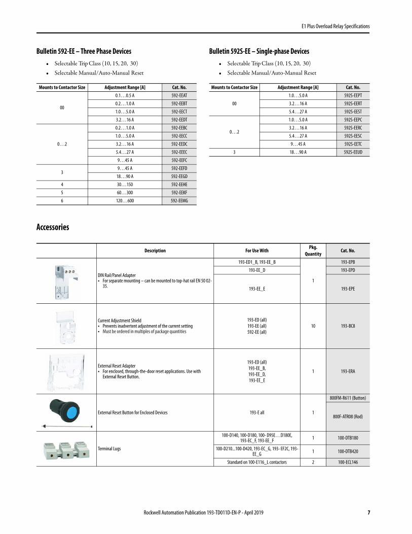
Bulletin 592-EE – Three Phase Devices• Selectable Trip Class (10, 15, 20, 30)• Selectable Manual/Auto-Manual Reset
Bulletin 592S-EE – Single-phase Devices• Selectable Trip Class (10, 15, 20, 30)• Selectable Manual/Auto-Manual Reset
Accessories
Mounts to Contactor Size Adjustment Range [A] Cat. No.
00
0.1…0.5 A 592-EEAT
0.2…1.0 A 592-EEBT
1.0…5.0 A 592-EECT
3.2…16 A 592-EEDT
0…2
0.2…1.0 A 592-EEBC
1.0…5.0 A 592-EECC
3.2…16 A 592-EEDC
5.4…27 A 592-EEEC
9…45 A 592-EEFC
39…45 A 592-EEFD
18…90 A 592-EEGD
4 30…150 592-EEHE
5 60…300 592-EEKF
6 120…600 592-EEMG
Mounts to Contactor Size Adjustment Range [A] Cat. No.
00
1.0…5.0 A 592S-EEPT
3.2…16 A 592S-EERT
5.4…27 A 592S-EEST
0…2
1.0…5.0 A 592S-EEPC
3.2…16 A 592S-EERC
5.4…27 A 592S-EESC
9…45 A 592S-EETC
3 18…90 A 592S-EEUD
Description For Use WithPkg.
QuantityCat. No.
DIN Rail/Panel Adapter• For separate mounting – can be mounted to top-hat rail EN 50 02-
35.
193-ED1_B, 193-EE_B
1
193-EPB
193-EE_D 193-EPD
193-EE_E 193-EPE
Current Adjustment Shield• Prevents inadvertent adjustment of the current setting• Must be ordered in multiples of package quantities
193-ED (all)193-EE (all)592-EE (all)
10 193-BC8
External Reset Adapter• For enclosed, through-the-door reset applications. Use with
External Reset Button.
193-ED (all)193-EE_B,193-EE_D,193-EE_E
1 193-ERA
External Reset Button for Enclosed Devices 193-E all 1
800FM-R611 (Button)
800F-ATR08 (Rod)
Terminal Lugs
100-D140, 100-D180, 100- D95E…D180E, 193-EC_F, 193-EE_F 1 100-DTB180
100-D210...100-D420, 193-EC_G, 193- EF2C, 193-EE_G 1 100-DTB420
Standard on 100-E116_L contactors 2 100-ECL146
Rockwell Automation Publication 193-TD011D-EN-P - April 2019 7
E1 Plus Overload Relay Specifications
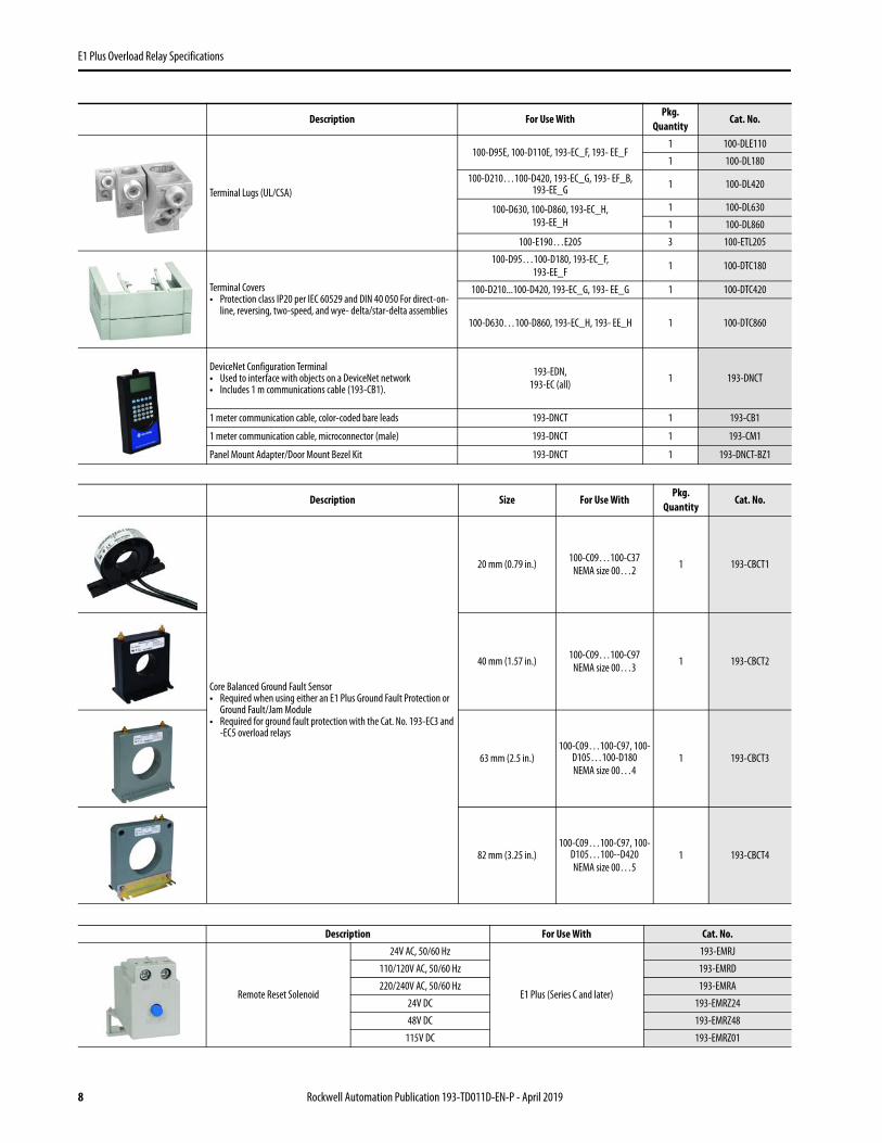
Terminal Lugs (UL/CSA)
100-D95E, 100-D110E, 193-EC_F, 193- EE_F1 100-DLE110
1 100-DL180
100-D210…100-D420, 193-EC_G, 193- EF_B, 193-EE_G 1 100-DL420
100-D630, 100-D860, 193-EC_H,193-EE_H
1 100-DL630
1 100-DL860
100-E190…E205 3 100-ETL205
Terminal Covers• Protection class IP20 per IEC 60529 and DIN 40 050 For direct-on-
line, reversing, two-speed, and wye- delta/star-delta assemblies
100-D95…100-D180, 193-EC_F,193-EE_F 1 100-DTC180
100-D210...100-D420, 193-EC_G, 193- EE_G 1 100-DTC420
100-D630…100-D860, 193-EC_H, 193- EE_H 1 100-DTC860
DeviceNet Configuration Terminal• Used to interface with objects on a DeviceNet network• Includes 1 m communications cable (193-CB1).
193-EDN,193-EC (all) 1 193-DNCT
1 meter communication cable, color-coded bare leads 193-DNCT 1 193-CB1
1 meter communication cable, microconnector (male) 193-DNCT 1 193-CM1
Panel Mount Adapter/Door Mount Bezel Kit 193-DNCT 1 193-DNCT-BZ1
Description Size For Use WithPkg.
QuantityCat. No.
Core Balanced Ground Fault Sensor• Required when using either an E1 Plus Ground Fault Protection or
Ground Fault/Jam Module• Required for ground fault protection with the Cat. No. 193-EC3 and
-EC5 overload relays
20 mm (0.79 in.) 100-C09…100-C37NEMA size 00…2 1 193-CBCT1
40 mm (1.57 in.) 100-C09…100-C97NEMA size 00…3 1 193-CBCT2
63 mm (2.5 in.)100-C09…100-C97, 100-
D105…100-D180NEMA size 00…4
1 193-CBCT3
82 mm (3.25 in.)100-C09…100-C97, 100-
D105…100--D420NEMA size 00…5
1 193-CBCT4
Description For Use With Cat. No.
Remote Reset Solenoid
24V AC, 50/60 Hz
E1 Plus (Series C and later)
193-EMRJ
110/120V AC, 50/60 Hz 193-EMRD
220/240V AC, 50/60 Hz 193-EMRA
24V DC 193-EMRZ24
48V DC 193-EMRZ48
115V DC 193-EMRZ01
Description For Use WithPkg.
QuantityCat. No.
8 Rockwell Automation Publication 193-TD011D-EN-P - April 2019
E1 Plus Overload Relay Specifications
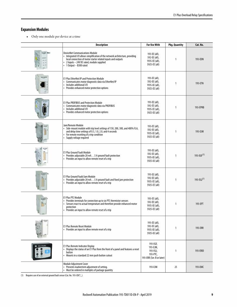
Expansion Modules• Only one module per device at a time
Description For Use With Pkg. Quantity Cat. No.
DeviceNet Communications Module• Integrated I/O allows simplification of the network architecture, providing
local connection of motor starter related inputs and outputs• 2 Inputs – 24V DC rated, module supplied• 1 Output – B300 rated
193-EE (all),592-EE (all),
193S-EE (all),592S-EE (all)
1 193-EDN
E1 Plus EtherNet/IP and Protection Module• Communicates motor diagnostic data via EtherNet/IP• Includes additional I/O• Provides enhanced motor protection options
193-EE (all),592-EE (all),
193S-EE (all),592S-EE (all)
1 193-ETN
E1 Plus PROFIBUS and Protection Module• Communicates motor diagnostic data via PROFIBUS• Includes additional I/O• Provides enhanced motor protection options
193-EE (all),592-EE (all),
193S-EE (all),592S-EE (all)
1 193-EPRB
Jam/Remote Module• Side-mount module with trip level settings of 150, 200, 300, and 400% FLA,
and delay time settings of 0.5, 1.0, 2.0, and 4 seconds• For remote resetting of a trip condition• Supply voltage required
193-EE (all),592-EE (all),
193S-EE (all),592S-EE (all)
1 193-EJM
E1 Plus Ground Fault Module• Provides adjustable 20 mA…5 A ground fault protection• Provides an input to allow remote reset of a trip
193-EE (all),592-EE (all),
193S-EE (all),592S-EE (all)
1 193-EGF(1)
(1) Requires use of an external ground fault sensor (Cat. No. 193-CBCT_).
E1 Plus Ground Fault/Jam Module• Provides adjustable 20 mA…5 A ground fault and fixed jam protection• Provides an input to allow remote reset of a trip
193-EE (all),592-EE (all),
193S-EE (all),592S-EE (all)
1 193-EGJ(1)
E1 Plus PTC Module• Provides terminals for connection up to six PTC thermistor sensors• Sensors react to actual temperature and therefore provide enhanced motor
protection• Provides an input to allow remote reset of a trip
193-EE (all),592-EE (all),
193S-EE (all),592S-EE (all)
1 193-EPT
E1 Plus Remote Reset Module• Provides an input to allow remote reset of a trip
193-EE (all),592-EE (all),
193S-EE (all),592S-EE (all)
1 193-ERR
E1 Plus Remote Indicator Display• Displays the status of an E1 Plus from the front of a panel and features a reset
button• Mounts in a standard 22 mm push button cutout
193-EGF,193-EJM,193-EGJ,193-PTC,
193-ERR (Ser. B or later)
1 193-ERID
Module Adjustment Cover • Prevents inadvertent adjustment of setting.• Must be ordered in multiples of package quantity
193-EJM 25 193-EMC
Rockwell Automation Publication 193-TD011D-EN-P - April 2019 9
E1 Plus Overload Relay Specifications
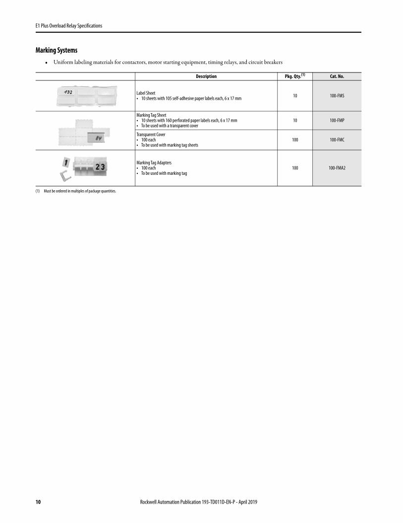
Marking Systems• Uniform labeling materials for contactors, motor starting equipment, timing relays, and circuit breakers
Description Pkg. Qty.(1)
(1) Must be ordered in multiples of package quantities.
Cat. No.
Label Sheet• 10 sheets with 105 self-adhesive paper labels each, 6 x 17 mm 10 100-FMS
Marking Tag Sheet• 10 sheets with 160 perforated paper labels each, 6 x 17 mm • To be used with a transparent cover
10 100-FMP
Transparent Cover• 100 each• To be used with marking tag sheets
100 100-FMC
Marking Tag Adapters• 100 each• To be used with marking tag
100 100-FMA2
10 Rockwell Automation Publication 193-TD011D-EN-P - April 2019
E1 Plus Overload Relay Specifications
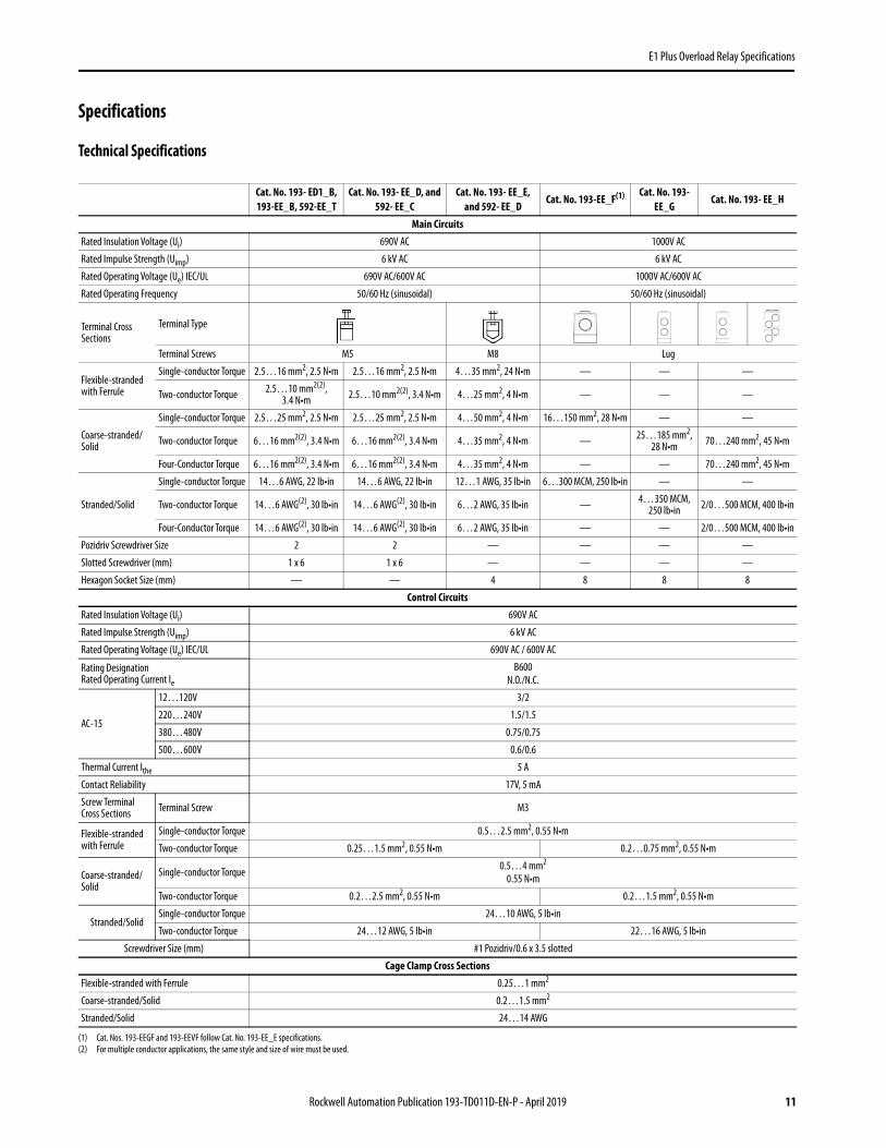
Specifications
Technical Specifications
Cat. No. 193- ED1_B, 193-EE_B, 592-EE_T
Cat. No. 193- EE_D, and 592- EE_C
Cat. No. 193- EE_E, and 592- EE_D
Cat. No. 193-EE_F(1)
(1) Cat. Nos. 193-EEGF and 193-EEVF follow Cat. No. 193-EE_E specifications.
Cat. No. 193-EE_G
Cat. No. 193- EE_H
Main CircuitsRated Insulation Voltage (Ui) 690V AC 1000V AC
Rated Impulse Strength (Uimp) 6 kV AC 6 kV AC
Rated Operating Voltage (Ue) IEC/UL 690V AC/600V AC 1000V AC/600V AC
Rated Operating Frequency 50/60 Hz (sinusoidal) 50/60 Hz (sinusoidal)
Terminal Cross Sections
Terminal Type
Terminal Screws M5 M8 Lug
Flexible-stranded with Ferrule
Single-conductor Torque 2.5…16 mm2, 2.5 N•m 2.5…16 mm2, 2.5 N•m 4…35 mm2, 24 N•m — — —
Two-conductor Torque 2.5…10 mm2(2), 3.4 N•m 2.5…10 mm2(2), 3.4 N•m 4…25 mm2, 4 N•m — — —
Coarse-stranded/Solid
Single-conductor Torque 2.5…25 mm2, 2.5 N•m 2.5…25 mm2, 2.5 N•m 4…50 mm2, 4 N•m 16…150 mm2, 28 N•m — —
Two-conductor Torque 6…16 mm2(2), 3.4 N•m
(2) For multiple conductor applications, the same style and size of wire must be used.
6…16 mm2(2), 3.4 N•m 4…35 mm2, 4 N•m — 25…185 mm2, 28 N•m 70…240 mm2, 45 N•m
Four-Conductor Torque 6…16 mm2(2), 3.4 N•m 6…16 mm2(2), 3.4 N•m 4…35 mm2, 4 N•m — — 70…240 mm2, 45 N•m
Stranded/Solid
Single-conductor Torque 14…6 AWG, 22 lb•in 14…6 AWG, 22 lb•in 12…1 AWG, 35 lb•in 6…300 MCM, 250 lb•in — —
Two-conductor Torque 14…6 AWG(2), 30 lb•in 14…6 AWG(2), 30 lb•in 6…2 AWG, 35 lb•in — 4…350 MCM, 250 lb•in 2/0…500 MCM, 400 lb•in
Four-Conductor Torque 14…6 AWG(2), 30 lb•in 14…6 AWG(2), 30 lb•in 6…2 AWG, 35 lb•in — — 2/0…500 MCM, 400 lb•in
Pozidriv Screwdriver Size 2 2 — — — —
Slotted Screwdriver (mm) 1 x 6 1 x 6 — — — —
Hexagon Socket Size (mm) — — 4 8 8 8
Control CircuitsRated Insulation Voltage (Ui) 690V AC
Rated Impulse Strength (Uimp) 6 kV AC
Rated Operating Voltage (Ue) IEC/UL 690V AC / 600V AC
Rating DesignationRated Operating Current Ie
B600N.O./N.C.
AC-15
12…120V 3/2
220…240V 1.5/1.5
380…480V 0.75/0.75
500…600V 0.6/0.6
Thermal Current Ithe 5 A
Contact Reliability 17V, 5 mA
Screw TerminalCross Sections Terminal Screw M3
Flexible-stranded with Ferrule
Single-conductor Torque 0.5…2.5 mm2, 0.55 N•m
Two-conductor Torque 0.25…1.5 mm2, 0.55 N•m 0.2…0.75 mm2, 0.55 N•m
Coarse-stranded/Solid
Single-conductor Torque 0.5…4 mm2
0.55 N•m
Two-conductor Torque 0.2…2.5 mm2, 0.55 N•m 0.2…1.5 mm2, 0.55 N•m
Stranded/SolidSingle-conductor Torque 24…10 AWG, 5 lb•in
Two-conductor Torque 24…12 AWG, 5 lb•in 22…16 AWG, 5 lb•in
Screwdriver Size (mm) #1 Pozidriv/0.6 x 3.5 slotted
Cage Clamp Cross SectionsFlexible-stranded with Ferrule 0.25…1 mm2
Coarse-stranded/Solid 0.2…1.5 mm2
Stranded/Solid 24…14 AWG
Rockwell Automation Publication 193-TD011D-EN-P - April 2019 11
E1 Plus Overload Relay Specifications
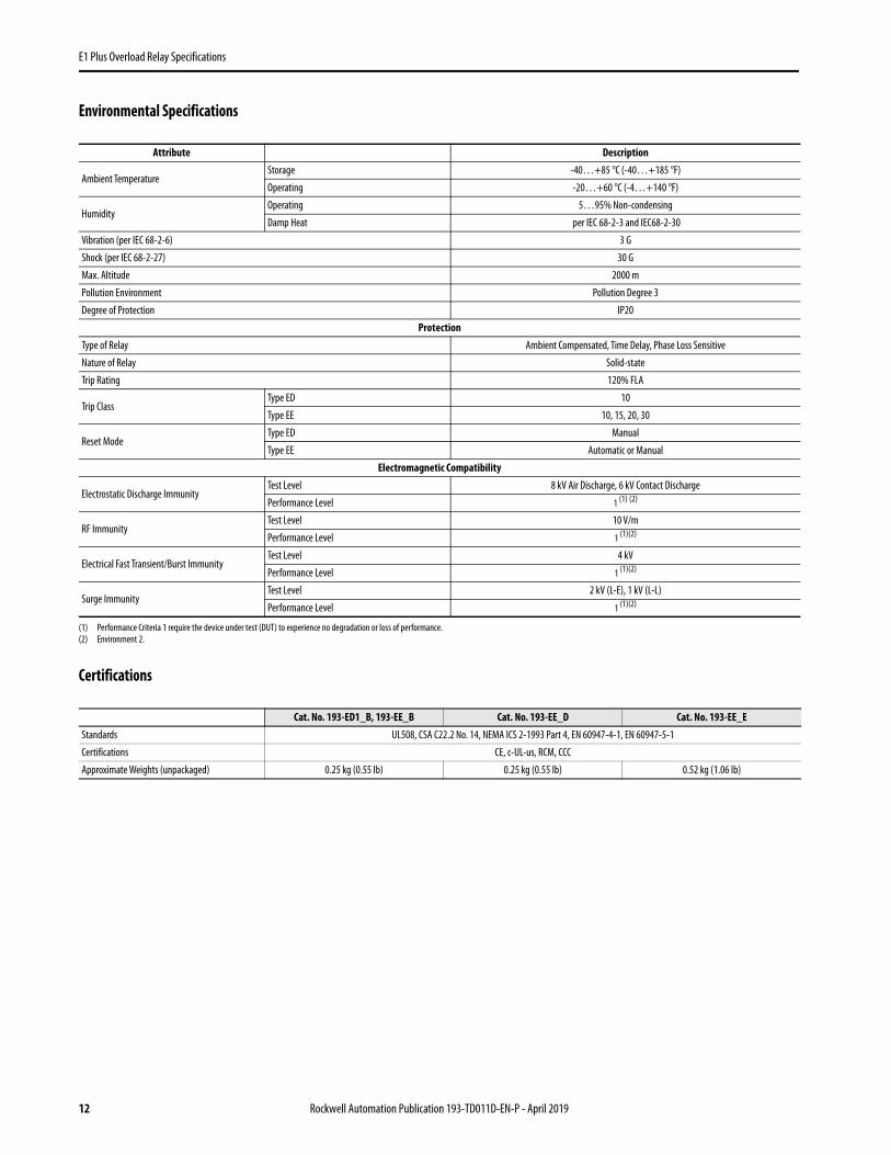
Environmental Specifications
Certifications
Attribute Description
Ambient TemperatureStorage -40…+85 °C (-40…+185 °F)
Operating -20…+60 °C (-4…+140 °F)
HumidityOperating 5…95% Non-condensing
Damp Heat per IEC 68-2-3 and IEC68-2-30
Vibration (per IEC 68-2-6) 3 G
Shock (per IEC 68-2-27) 30 G
Max. Altitude 2000 m
Pollution Environment Pollution Degree 3
Degree of Protection IP20
ProtectionType of Relay Ambient Compensated, Time Delay, Phase Loss Sensitive
Nature of Relay Solid-state
Trip Rating 120% FLA
Trip ClassType ED 10
Type EE 10, 15, 20, 30
Reset ModeType ED Manual
Type EE Automatic or Manual
Electromagnetic Compatibility
Electrostatic Discharge ImmunityTest Level 8 kV Air Discharge, 6 kV Contact Discharge
Performance Level 1 (1) (2)
(1) Performance Criteria 1 require the device under test (DUT) to experience no degradation or loss of performance.(2) Environment 2.
RF ImmunityTest Level 10 V/m
Performance Level 1 (1)(2)
Electrical Fast Transient/Burst ImmunityTest Level 4 kV
Performance Level 1 (1)(2)
Surge ImmunityTest Level 2 kV (L-E), 1 kV (L-L)
Performance Level 1 (1)(2)
Cat. No. 193-ED1_B, 193-EE_B Cat. No. 193-EE_D Cat. No. 193-EE_E
Standards UL508, CSA C22.2 No. 14, NEMA ICS 2-1993 Part 4, EN 60947-4-1, EN 60947-5-1
Certifications CE, c-UL-us, RCM, CCC
Approximate Weights (unpackaged) 0.25 kg (0.55 lb) 0.25 kg (0.55 lb) 0.52 kg (1.06 lb)
12 Rockwell Automation Publication 193-TD011D-EN-P - April 2019
E1 Plus Overload Relay Specifications
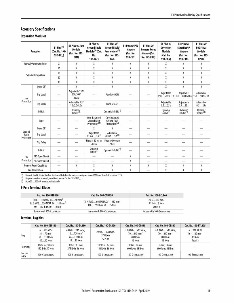
Accessory SpecificationsExpansion Modules
3-Pole Terminal Blocks
Terminal Lug Kits
FunctionE1 Plus(1)
(Cat. No. 193/592- EE_)
(1) Dynamic Inhibit: Protective function is enabled after the motor current goes above 150% and then falls to below 125%.
E1 Plus w/ Jam Module
(Cat. No. 193-EJM)
E1 Plus w/ Ground Fault
Module(2) (Cat. No.
193-EGF)
(2) Requires use of an external ground fault sensor, Cat. No. 193-CBCT_.
E1 Plus w/ Ground Fault/Jam Module(2) (Cat. No. 193-
EGJ)
E1 Plus w/ PTC Module(Cat. No.193-EPT)
E1 Plus w/ Remote Reset Module (Cat. No. 193-ERR)
E1 Plus w/ DeviceNet
Module(Cat. No.193-EDN)
E1 Plus w/ EtherNet/IP
Module (Cat. No.193-ETN)
E1 Plus w/ PROFIBUS
Module (Cat. No. 193-
EPRB)Manual/Automatic Reset X X X X X X X X X
Selectable Trip Class
10 X X X X X X X X
15 X X X X X X X X
20 X X X X X X X X
30 X X X X X X X X
Jam Protection
On or Off — X — X — — X X X
Trip Level —Adjustable 150/
200/300/400%
— Fixed @ 400% — — Adjustable 150…600% FLA
Adjustable 150…600% FLA
Adjustable 150…600% FLA
Trip Delay — Adjustable 0.5/1.0/2.0/4.0 s — Fixed @ 0.5 s — — Adjustable
0.5…25 sAdjustable 0.5…25 s
Adjustable 0.5…25 s
Inhibit — Dynamic Inhibit(1) — Dynamic Inhibit(1) — — Dynamic
Inhibit(1)Dynamic Inhibit(1)
Dynamic Inhibit(1)
Ground Fault
Protection
Type — —Core-balanced Ground Fault Protection(2)
Core-balanced Ground Fault Protection(2)
— — — — —
On or Off — — X X — — — — —
Trip Level — — Adjustable 20 mA…5 A(3)
(3) From 20…100 mA for resistive loads only.
Adjustable 20 mA…5 A(3) — — — — —
Trip Delay — — Fixed @ 50 ms ±20 ms
Fixed @ 50 ms ±20 ms — — — — —
Inhibit — — Dynamic Inhibit(1) Dynamic Inhibit(1) — — — — —
PTCProtection
PTC Open Circuit — — — — X — — — —
PTC Short Circuit — — — — X — — — —
Remote Reset Capability — X X X X X X X X
Fault Indication — — X X X — X X X
Cat. No. 100-DTB180 Cat. No. 100-DTB420 Cat. No. 100-ECL146(A) 6…1/0 AWG, 16…50 mm2
(B) 6 AWG…250 MCM, 16…120 mm2
90…110 lb•in, 10…12 N•m
(2) 4 AWG…600 MCM, 25…240 mm2
180…220 lb•in, 20…25 N•m
2 x 6…3/0 AWG71 lb•in., 8 N•m
Set of 2
for use with 100-C contactors for use with 100-C contactors for use with 100-E contactors
Cat. No. 100-DLE110 Cat. No. 100-DL180 Cat. No. 100-DL420 Cat. No. 100-DL630 Cat. No. 100-DL860 Cat. No. 100-ETL205
Lug
6…2/0 AWG16…70 mm2
90…110 lb•in10…12 N•m
6 AWG…250 MCM, 16…120 mm2
90…110 lb•in10…12 N•m
2 AWG…350MCM,375 lb•in42 N•m
2/0 AWG…500 MCM,70…240 mm2
400 lb•in45 N•m
2/0 AWG…500 MCM,70…240 mm2
400 lb•in45 N•m
6…300 MCM16…120 mm2
18 N•mSet of 3
Terminal 13/32 in., 10 mm 150 lb•in, 17 N•m
1/2 in., 13 mm 275 lb•in, 16 N•m
11/16 in., 17 mm 140 lb•in, 16 N•m
3/4 in., 19 mm 600 lb•in, 68 N•m
3/4 in., 19 mm 600 lb•in, 68 N•m —
For use with 100-C contactors 100-C contactors 100-C contactors 100-C contactors 100-C contactors 100-E contactors
Rockwell Automation Publication 193-TD011D-EN-P - April 2019 13
E1 Plus Overload Relay Specifications
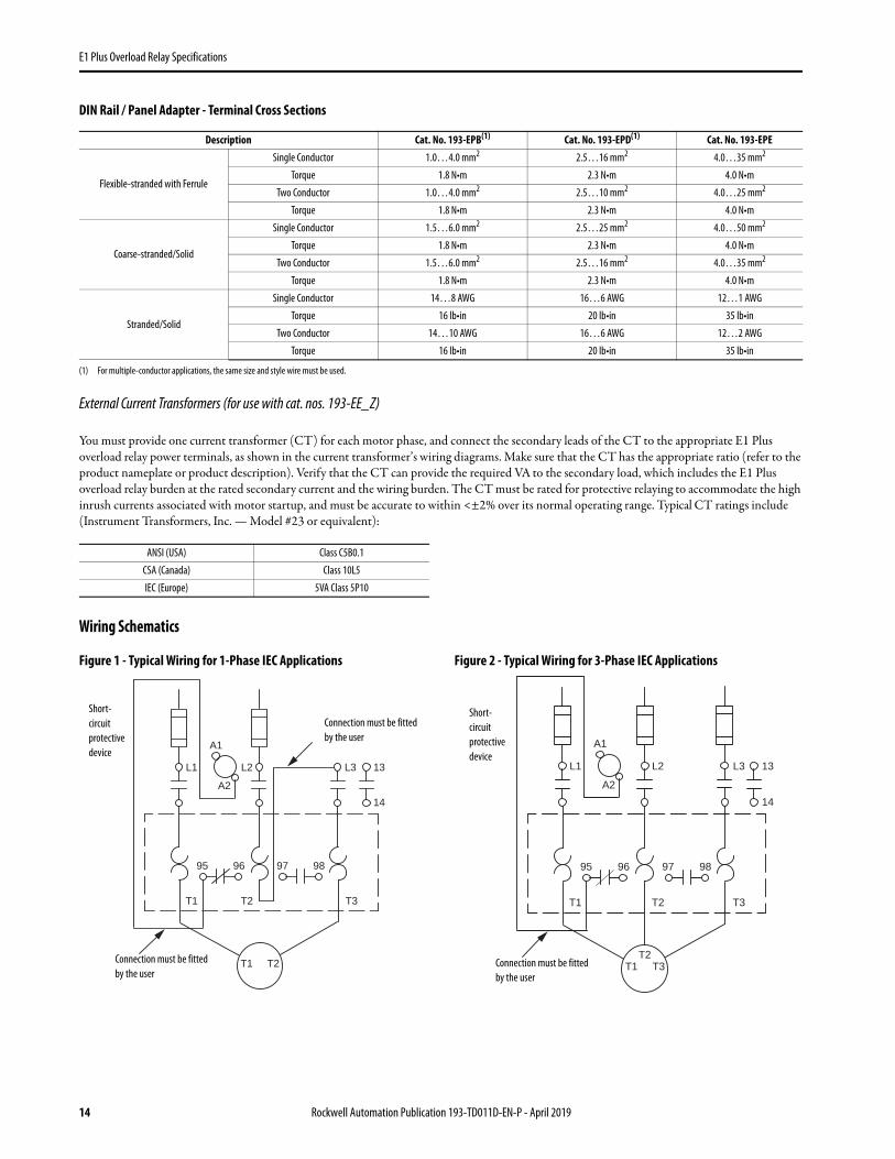
DIN Rail / Panel Adapter - Terminal Cross Sections
External Current Transformers (for use with cat. nos. 193-EE_Z)
You must provide one current transformer (CT) for each motor phase, and connect the secondary leads of the CT to the appropriate E1 Plus overload relay power terminals, as shown in the current transformer’s wiring diagrams. Make sure that the CT has the appropriate ratio (refer to the product nameplate or product description). Verify that the CT can provide the required VA to the secondary load, which includes the E1 Plus overload relay burden at the rated secondary current and the wiring burden. The CT must be rated for protective relaying to accommodate the high inrush currents associated with motor startup, and must be accurate to within <±2% over its normal operating range. Typical CT ratings include (Instrument Transformers, Inc. — Model #23 or equivalent):
Wiring Schematics
Figure 1 - Typical Wiring for 1-Phase IEC Applications Figure 2 - Typical Wiring for 3-Phase IEC Applications
Description Cat. No. 193-EPB(1) Cat. No. 193-EPD(1) Cat. No. 193-EPE
Flexible-stranded with Ferrule
Single Conductor 1.0…4.0 mm2 2.5…16 mm2 4.0…35 mm2
Torque 1.8 N•m 2.3 N•m 4.0 N•m
Two Conductor 1.0…4.0 mm2 2.5…10 mm2 4.0…25 mm2
Torque 1.8 N•m 2.3 N•m 4.0 N•m
Coarse-stranded/Solid
Single Conductor 1.5…6.0 mm2 2.5…25 mm2 4.0…50 mm2
Torque 1.8 N•m 2.3 N•m 4.0 N•m
Two Conductor 1.5…6.0 mm2 2.5…16 mm2 4.0…35 mm2
Torque 1.8 N•m 2.3 N•m 4.0 N•m
Stranded/Solid
Single Conductor 14…8 AWG 16…6 AWG 12…1 AWG
Torque 16 lb•in 20 lb•in 35 lb•in
Two Conductor 14…10 AWG 16…6 AWG 12…2 AWG
Torque 16 lb•in 20 lb•in 35 lb•in
(1) For multiple-conductor applications, the same size and style wire must be used.
ANSI (USA) Class C5B0.1
CSA (Canada) Class 10L5
IEC (Europe) 5VA Class 5P10
95
L2 L3 13L1
14
A1
A2
T2 T3T1
96 97 98
T1 T2
Short-circuit protective device
Connection must be fitted by the user
Connection must be fitted by the user
95
L2 L3 13L1
14
A1
A2
T2 T3T1
96 97 98
T1 T3T2
Short-circuit protective device
Connection must be fitted by the user
14 Rockwell Automation Publication 193-TD011D-EN-P - April 2019
E1 Plus Overload Relay Specifications
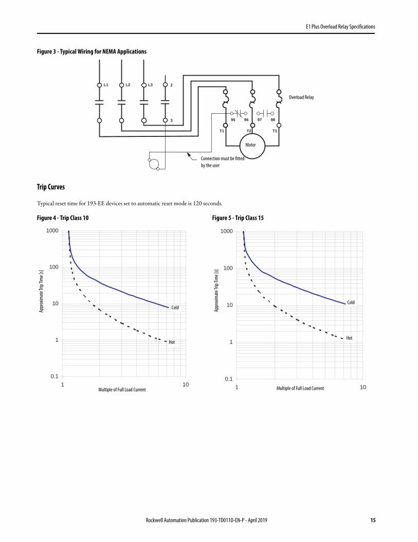
Figure 3 - Typical Wiring for NEMA Applications
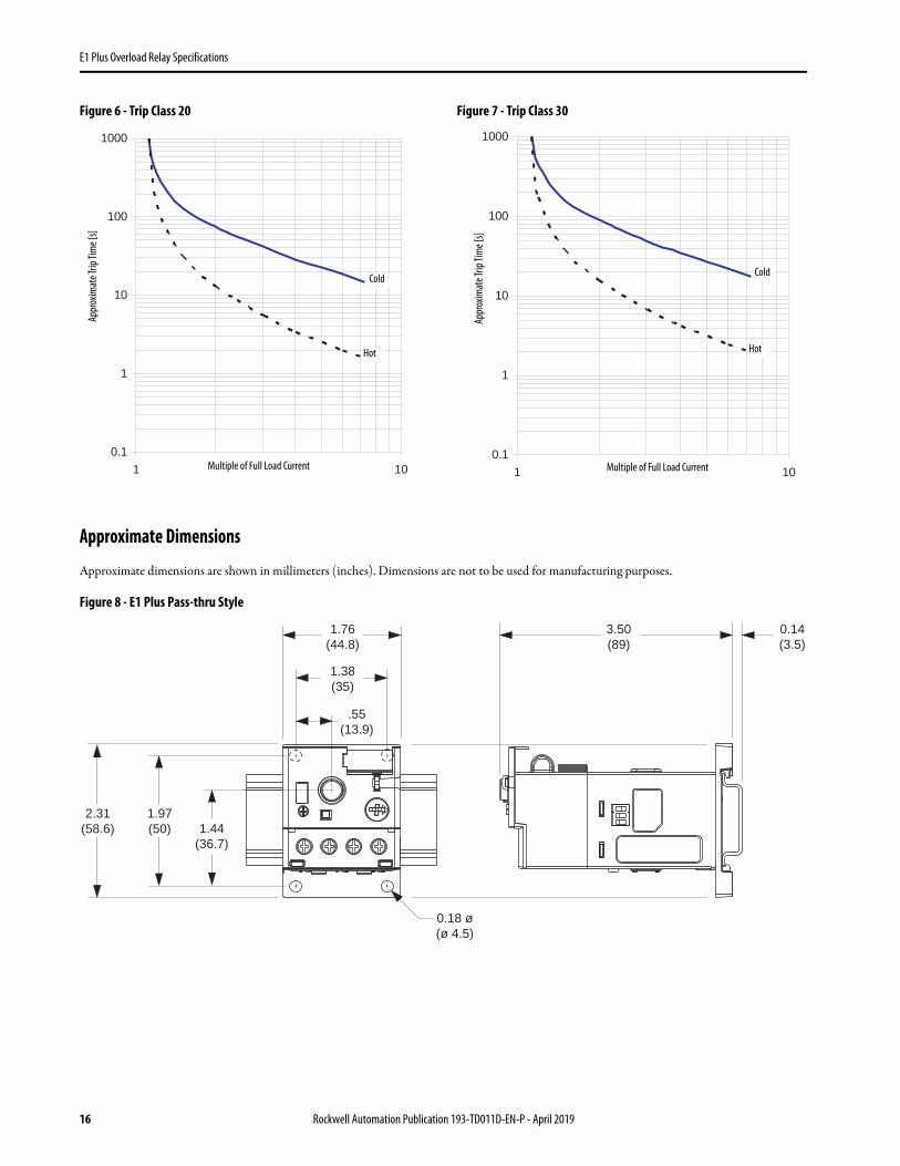
Trip Curves
Typical reset time for 193-EE devices set to automatic reset mode is 120 seconds.
Figure 4 - Trip Class 10 Figure 5 - Trip Class 15
L3L2L1
T3T2T1
3
2
9695 9897
Connection must be fitted by the user
Overload Relay
Motor
0.1
1
10
100
1000
1 10
Appr
oxim
ate T
rip Ti
me [
s]
Multiple of Full Load Current
Hot
Cold
0.1
1
10
100
1000
1 10
Appr
oxim
ate T
rip Ti
me [
s]
Multiple of Full Load Current
Hot
Cold
Rockwell Automation Publication 193-TD011D-EN-P - April 2019 15
E1 Plus Overload Relay Specifications
Figure 6 - Trip Class 20 Figure 7 - Trip Class 30
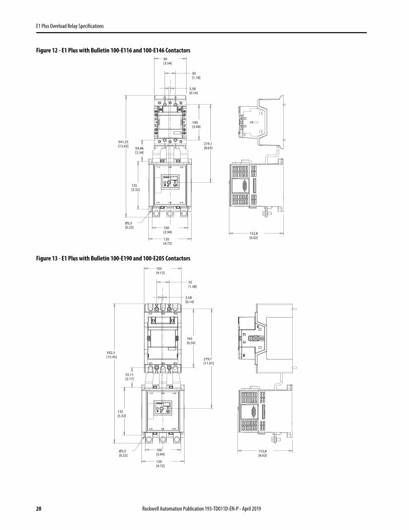
Approximate Dimensions
Approximate dimensions are shown in millimeters (inches). Dimensions are not to be used for manufacturing purposes.
Figure 8 - E1 Plus Pass-thru Style
0.1
1
10
100
1000
1 10
Appr
oxim
ate T
rip Ti
me [
s]
Multiple of Full Load Current
Hot
Cold
0.1
1
10
100
1000
1 10Ap
prox
imat
e Trip
Tim
e [s]
Multiple of Full Load Current
Hot
Cold
1.76(44.8)
1.38(35)
.55(13.9)
0.18 ø(ø 4.5)
0.14(3.5)
3.50(89)
2.31(58.6)
1.97(50) 1.44
(36.7)
16 Rockwell Automation Publication 193-TD011D-EN-P - April 2019
E1 Plus Overload Relay Specifications
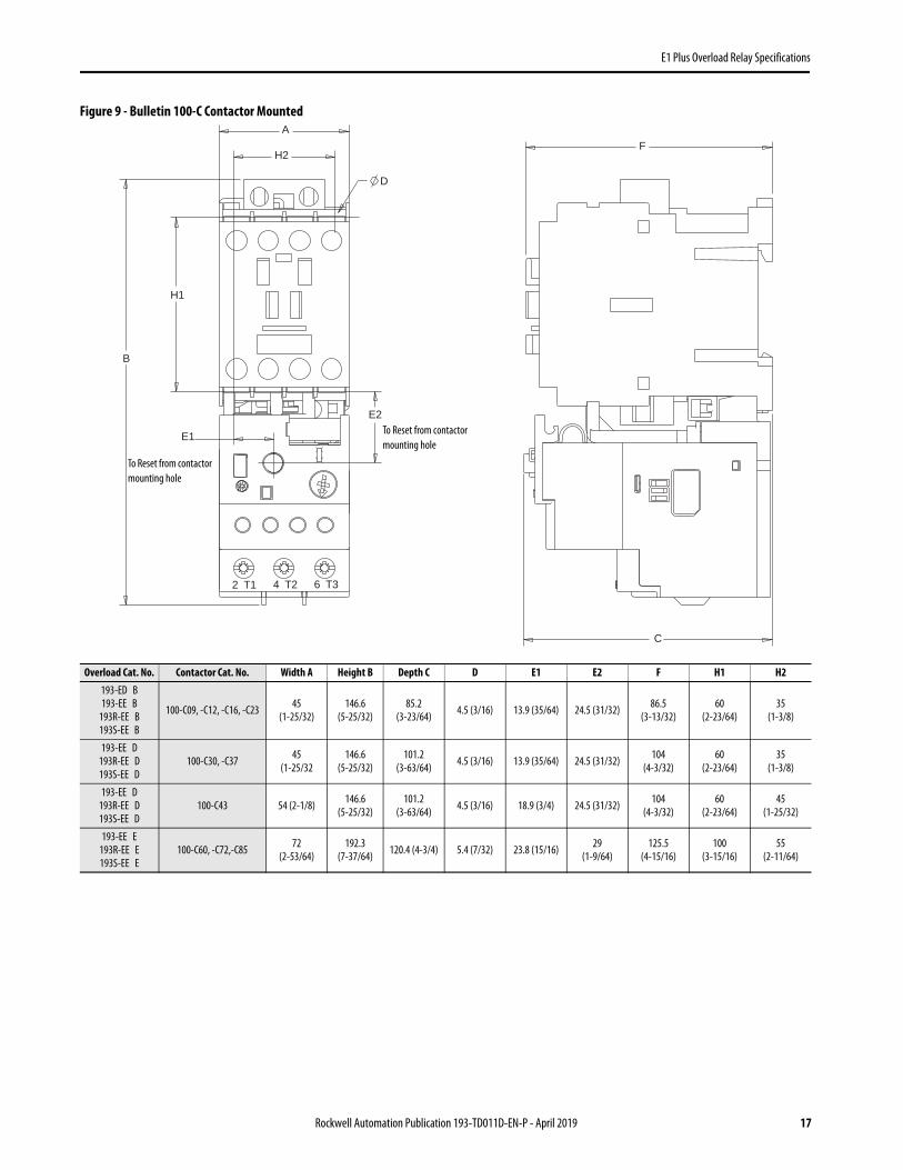
Figure 9 - Bulletin 100-C Contactor Mounted
Overload Cat. No. Contactor Cat. No. Width A Height B Depth C D E1 E2 F H1 H2193-ED B193-EE B
193R-EE B193S-EE B
100-C09, -C12, -C16, -C23 45(1-25/32)
146.6(5-25/32)
85.2 (3-23/64) 4.5 (3/16) 13.9 (35/64) 24.5 (31/32) 86.5
(3-13/32)60
(2-23/64)35
(1-3/8)
193-EE D193R-EE D193S-EE D
100-C30, -C37 45(1-25/32
146.6 (5-25/32)
101.2(3-63/64) 4.5 (3/16) 13.9 (35/64) 24.5 (31/32) 104
(4-3/32)60
(2-23/64)35
(1-3/8)
193-EE D193R-EE D193S-EE D
100-C43 54 (2-1/8) 146.6 (5-25/32)
101.2(3-63/64) 4.5 (3/16) 18.9 (3/4) 24.5 (31/32) 104
(4-3/32)60
(2-23/64)45
(1-25/32)
193-EE E193R-EE E193S-EE E
100-C60, -C72,-C85 72(2-53/64)
192.3(7-37/64) 120.4 (4-3/4) 5.4 (7/32) 23.8 (15/16) 29
(1-9/64)125.5
(4-15/16)100
(3-15/16)55
(2-11/64)
A
D
H2
E2
E1
H1
B
2 T1 4 T2 6 T3
F
C
To Reset from contactor mounting hole
To Reset from contactor mounting hole
Rockwell Automation Publication 193-TD011D-EN-P - April 2019 17
E1 Plus Overload Relay Specifications
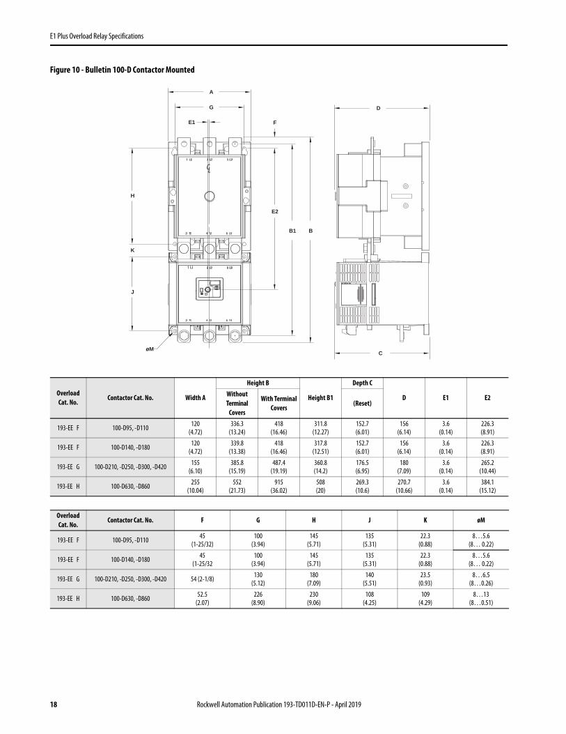
Figure 10 - Bulletin 100-D Contactor Mounted
Overload Cat. No.
Contactor Cat. No. Width A
Height B
Height B1
Depth C
D E1 E2Without Terminal
Covers
With Terminal Covers
(Reset)
193-EE F 100-D95, -D110 120(4.72)
336.3(13.24)
418(16.46)
311.8(12.27)
152.7(6.01)
156(6.14)
3.6(0.14)
226.3(8.91)
193-EE F 100-D140, -D180 120(4.72)
339.8(13.38)
418(16.46)
317.8(12.51)
152.7(6.01)
156(6.14)
3.6(0.14)
226.3(8.91)
193-EE G 100-D210, -D250, -D300, -D420 155(6.10)
385.8(15.19)
487.4(19.19)
360.8(14.2)
176.5(6.95)
180(7.09)
3.6(0.14)
265.2(10.44)
193-EE H 100-D630, -D860 255(10.04)
552(21.73)
915(36.02)
508(20)
269.3(10.6)
270.7(10.66)
3.6(0.14)
384.1(15.12)
Overload Cat. No.
Contactor Cat. No. F G H J K øM
193-EE F 100-D95, -D110 45(1-25/32)
100(3.94)
145(5.71)
135(5.31)
22.3(0.88)
8…5.6(8… 0.22)
193-EE F 100-D140, -D180 45(1-25/32
100(3.94)
145(5.71)
135(5.31)
22.3(0.88)
8…5.6(8… 0.22)
193-EE G 100-D210, -D250, -D300, -D420 54 (2-1/8) 130(5.12)
180(7.09)
140(5.51)
23.5(0.93)
8…6.5(8…0.26)
193-EE H 100-D630, -D860 52.5(2.07)
226(8.90)
230(9.06)
108(4.25)
109(4.29)
8…13(8…0.51)
BB1
F
G
E1
C
D
A
E2
J
K
øM
H
CL
18 Rockwell Automation Publication 193-TD011D-EN-P - April 2019
E1 Plus Overload Relay Specifications
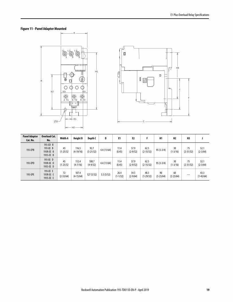
Figure 11 - Panel Adapter Mounted
Panel Adapter Cat. No.
Overload Cat. No.
Width A Height B Depth C D E1 E2 F H1 H2 H3 J
193-EPB
193-ED B193-EE B
193R-EE B193S-EE B
45(1-25/32
116.5 (4-19/16)
92.7 (3-21/32) 4.4 (11/64) 11.4
(0.45)57.9
(2-9/32)62.5
(2-15/32) 95 (3-3/4) 30(1-3/16)
75(2-31/32)
52.1 (2-3/64)
193-EPD193-EE D
193R-EE D193S-EE D
45(1-25/32
112.4 (4-7/16)
108.7 (4-9/32) 4.4 (11/64) 11.4
(0.45)57.9
(2-9/32)62.5
(2-15/32) 95 (3-3/4) 30(1-3/16)
75(2-31/32)
52.1 (2-3/64)
193-EPE193-EE E
193R-EE E193S-EE E
72(2-53/64)
107.4 (4-15/64) 127 (5/32) 5.5 (5/32) 26.4
(1-1/32)54.5
(2-9/64)48.3
(1-29/32)90
(3-23/64)60
(2-23/64) — 43.3 (1-45/64)
2 T1 4 T2 6 T3
H3
J
F
C
A
H1
E1D
H2
E2
B
L1
1 3 5
L 2 L3
Rockwell Automation Publication 193-TD011D-EN-P - April 2019 19
E1 Plus Overload Relay Specifications
Figure 12 - E1 Plus with Bulletin 100-E116 and 100-E146 Contactors
Figure 13 - E1 Plus with Bulletin 100-E190 and 100-E205 Contactors
30[1.18]
100[3.94]
135[5.32]
100[3.94]
90[3.54]
120[4.72]
341,23[13.43]
219,1[8.63]
3,58[0.14]
Ø5,5[0.22]
59,46[2.34]
152,8[6.02]
35[1.38]
165[6.50]
279,7[11.01]
3,58[0.14]
100[3.94]
135[5.32]
55,11[2.17]
120[4.72]
[0.22]
105[4.13]
392,3[15.45]
152,8[6.02]
Ø5,5
20 Rockwell Automation Publication 193-TD011D-EN-P - April 2019

E1 Plus Overload Relay Specifications
Additional ResourcesThese documents contain additional information concerning related products from Rockwell Automation.
You can view or download publications at http://www.rockwellautomation.com/global/literature-library/overview.page.
Resource Description
Industrial Automation Wiring and Grounding Guidelines, publication 1770-4.1 Provides general guidelines for installing a Rockwell Automation industrial system.
Product Certifications website, rok.auto/certifications. Provides declarations of conformity, certificates, and other certification details.
Rockwell Automation Publication 193-TD011D-EN-P - April 2019 21
Allen-Bradley, ControlLogix, E1 Plus, Integrated Architecture, LISTEN. THINK. SOLVE., Rockwell Automation, and Rockwell Software are trademarks of Rockwell Automation, Inc.DeviceNet and EtherNet/IP are trademarks of ODVA, Inc.Trademarks not belonging to Rockwell Automation are property of their respective companies.
Publication 193-TD011D-EN-P - April 2019
Rockwell Automation SupportUse the following resources to access support information.
Documentation FeedbackYour comments will help us serve your documentation needs better. If you have any suggestions on how to improve this document, complete the How Are We Doing? form at http://literature.rockwellautomation.com/idc/groups/literature/documents/du/ra-du002_-en-e.pdf.
Technical Support Center Knowledgebase Articles, How-to Videos, FAQs, Chat, User Forums, and Product Notification Updates. www.rockwellautomation.com/knowledgebase
Local Technical Support Phone Numbers Locate the phone number for your country. www.rockwellautomation.com/global/support/get-support-now.page
Direct Dial Codes Find the Direct Dial Code for your product. Use the code to route your call directly to a technical support engineer. www.rockwellautomation.com/global/support/direct-dial.page
Literature Library Installation Instructions, Manuals, Brochures, and Technical Data. www.rockwellautomation.com/literature
Product Compatibility and Download Center (PCDC)
Get help determining how products interact, check features and capabilities, and find associated firmware. www.rockwellautomation.com/global/support/pcdc.page
Rockwell Otomasyon Ticaret A.Ş., Kar Plaza İş Merkezi E Blok Kat:6 34752 İçerenköy, İstanbul, Tel: +90 (216) 5698400
Rockwell Automation maintains current product environmental information on its website at http://www.rockwellautomation.com/rockwellautomation/about-us/sustainability-ethics/product-environmental-compliance.page.
Supersedes Publication 193-TD011C-EN-P - May 2018 Copyright © 2019 Rockwell Automation, Inc. All rights reserved. Printed in the U.S.A.