Embed Size (px)
Citation preview
Technical Data
E1 Plus Overload Relay SpecificationsBulletin Number 193, 592
Additional Resources
These documents contain additional information concerning related products from Rockwell Automation.
You can view or download publications at http://www.rockwellautomation.com/literature/. To order paper copies of technical documentation, contact your local Allen-Bradley distributor or Rockwell Automation sales representative.
Topic Page
Product Overview 2
Standards Compliance and Certifications 2
Features 3
Catalog Number Explanation 4
General Specifications 5
Approximate Dimensions 10
Resource Description
Industrial Automation Wiring and Grounding Guidelines, publication 1770-4.1 Provides general guidelines for installing a Rockwell Automation industrial system.
Product Certifications website, http://www.ab.com Provides declarations of conformity, certificates, and other certification details.
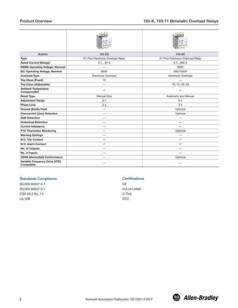
Product Overview 193-K, 193-T1 Bimetallic Overload Relays
Rockwell Automation Publication 193-TD011A-EN-P2
Bulletin 193-ED 193-EE
Type E1 Plus Electronic Overload Relay E1 Plus Electronic Overload Relay
Rated Current (Range) 0.1…45 A 0.1…800 A
NEMA Operating Voltage, Nominal — 600V
IEC Operating Voltage, Nominal 690V 690/1000V
Overload Type Electronic Overload Electronic Overload
Trip Class (Fixed) 10 —
Trip Class (Adjustable) — 10, 15, 20, 30
Ambient TemperatureCompensated � �
Reset Type Manual Only Automatic and Manual
Adjustment Range 5:1 5:1
Phase Loss 3 s 3 s
Ground (Earth) Fault — Optional
Overcurrent (Jam) Detection — Optional
Stall Detection — —
Underload Detection — —
Current Imbalance — —
PTC Thermistor Monitoring — Optional
Warning Settings — —
N.C. Trip Contact � �
N.O. Alarm Contact � �
No. of Outputs — —
No. of Inputs — —
ODVA (DeviceNet) Conformance — Optional
Variable Frequency Drive (VFD)Compatible — —
Standards Compliance
IEC/EN 60947-4-1
IEC/EN 60947-5-1
CSA 22.2 No. 14
UL 508
Certifications
CE
cULus Listed
C-Tick
CCC

E1 Plus Overload Relays Features
Accurate, Reliable PerformanceCurrent measurement-based protectionWhile electromechanical overload relays pass motor current throughheating elements to provide an indirect simulation of motor heating,the E1 Plus Overload Relay directly measures motor current. Currentmeasurement-based overload protection more accurately models amotor’s thermal condition. Furthermore, ambient temperature doesnot impact the performance of current measurement-based designsover the specified temperature operating range.
Electronic designThermal modeling is performed electronically with precision solid-state components, where at the heart of the E1 Plus Overload Relayis an application-specific integrated circuit (ASIC). The ASICcontinually processes motor current data to accurately maintain thetime-current status of the motor thermal capacity utilization value.
Thermal memoryA thermal memory circuit allows the E1 Plus Overload Relay tomodel the heating and cooling effects of motor on and off periods.This ensures accurate protection for both hot and cold motors.
Enhanced phase loss protectionA separate phase loss detection circuit incorporated into the E1Plus Overload Relay allows it to respond quickly to phase lossconditions; typical reaction time is 3 seconds.
Easy to Select and ApplyStraightforward installationThe self-powered design means that the E1 Plus Overload Relayinstalls in the same manner as traditional overload relays. Devicesetup is accomplished by simply dialing the setting potentiometer tothe motor FLA rating. The low energy consumption of the electronicdesign minimizes temperature rise issues inside control cabinets.
Wide adjustment rangeA wide 5:1 adjustment range results in the need for half as manycatalog numbers as the bimetallic alternative in order to cover thesame current range. This helps to reduce inventory carrying costsand affords greater installation flexibility for dual voltage machines.Evenly spaced setting tick marks enhance the ease of installationsetup.
Rugged ConstructionOver-molded power connectionsThe unique line-side over-molded power connections make for asturdy two-component starter assembly that is unmatched in theindustry. The pre-formed power connections allow easy starterassembly — every time.
Current transformersThe current transformers are secured separately in the overloadhousing to ensure the greatest degree of resistance to shock andvibration conditions. Varnished laminations ensure consistentperformance and provide additional protection against corrosion.
Latching relayThe robust design of the bi-polar latching relay provides reliable tripand reset performance for the most demanding of applications. Theself-enclosed relay offers additional environmental protection for usein industrial applications.
Application FlexibilityIsolated ContactsThe isolated contact configuration allows the N.C. and N.O.contacts to be applied in circuits operating at different voltage levelsand without polarity restrictions. The B600 contact rating affordsapplication in circuits rated to 600V.
DIP switch settingsBul. 193-EE devices offer DIP switch settings to select the trip class(10, 15, 20 or 30) and the reset mode (manual or automatic), makingthese devices extremely versatile.
Pass-Thru OptionThe E1 Plus Pass-Thru consumes 48% less panel space comparedto a standard E1 Plus mounted in a panel mount adapter. Thedesign provides an integrated DIN Rail mount and panel mountingholes and is intended for the following aplications: DIN Rail andPanel Mount Applications, Bulletin 100-K mini contactor, externalcurrent transformers, and for use with non Allen-Bradley Contactors.The E1 Plus Pass-Thru Electronic Overload Relay provides all of thesame expandable protection & communication capabilities as astandard E1 Plus, and eliminates the need for a separate panelmount adapter, which saves money and valuable panel space.
Side-Mount Expansion ModulesThrough the use of optional side-mount expansion modules,functionality of the E1 Plus overload relays can be cost effectivelyexpanded and machine operation and protection enhanced. Directmounting to the left side of the 193-EE and 592-EE E1 Plusoverload relays means that only 18 mm is added to the overallproduct width. The side-mounted accessory modules electronicallyinterface with the E1 Plus overload relay so that all control circuitconnections are made at the E1 Plus overload relay terminals.
E1 Plus DeviceNet™ Communication ModuleThe Bul. 193-EDN DeviceNet Communication Side-Mount Moduleprovides a cost-effective, seamless deployment of motor startersonto the Integrated Architecture™ as an accessory for the E1 Pluselectronic overload relay. The DeviceNet module providesIntegrated I/O (2 inputs and 1 output) providing local connection ofmotor starter-related I/O. The DeviceNet module offers expandedprotective functions including overload warning, jam protection, andunderload warning. The DeviceNet module also allows access toaverage motor current (percentage of FLA setting), percentage ofthermal capacity usage, device status, trip & warning identification,and trip history which allows continual monitoring of motorperformance.
E1 Plus Remote Reset ModuleThe Bul. 193-ERR Remote Reset Module is available forapplications that require remote reset of the E1 Plus overload relaysafter a trip occurs.
E1 Plus Jam Protection Module with Remote Reset
The Bul. 193-EJM Jam Protection Module provides front-accessibleDIP switches which offers flexibility to provide jam protection tomatch application requirements. Selections are available forenabling or disabling the jam protection function and remote resetoperation. Jam trip level settings are available at 150%, 200%,300%, and 400% of full load current setting. Trip delay settings of1/2, 1, 2, and 4 seconds are available to minimize nuisance trippingin applications where intermittent short-duration overloading ispermissible.
E1 Plus Ground Fault Module with Remote ResetThe Bul. 193-EGF Ground Fault Protection Module offers front-accessible DIP switches providing flexibility to configure groundfault protection to match application requirements. Selections areavailable for enabling or disabling the ground fault protectionfunction and remote reset operation. Ground fault trip level settingsare available in four ranges: 20…100 mA (resistive loads only, formotor loads consult your local Rockwell Automation sales office orAllen-Bradley distributor), 100…500 mA, 0.2…1 A, and 1…5 A.Within each range, the specific ground fault trip level can be set(20%, 35%, 50%, 65%, 80%, 90%, or 100% of the maximumground fault setting). Trip delay is fixed at 50 ms ± 20 ms.
Rockwell Automation Publication 193-TD011A-EN-P
Features/Cat. No. Explanation E1 Plus Overload Relays
E1 Plus Ground Fault/Jam Module with Remote ResetThe Bul. 193-EGJ Ground Fault/Jam Protection Module offers front-accessible DIP switches to provide flexibility to configure groundfault and jam protection to match application requirements. Theground fault selections are the same as the Bul. 193-EGF GroundFault Protection Module. In addition to ground fault, this moduleoffers selectable fixed jam protection. The user can enable ordisable jam protection from the DIP switches. The jam protection isfixed at 400% of the full load current setting with a 0.5 second tripdelay.
E1 Plus PTC Module with Remote ResetThe Bul. 193-EPT PTC Side-Mount Module provides two terminalsfor the connection of positive temperature coefficient (PTC)thermistor sensors. PTC sensors are commonly embedded in themotor stator windings to monitor winding temperature. PTCsensors react to actual temperature, so enhanced motor protectioncan be provided to address conditions like obstructed cooling andhigh ambient temperature.
E1 Plus EtherNet/IP ModuleThe Bul. 193-ETN EtherNet/IP network communication moduledelivers seamless control and direct access to motor performanceand diagnostic data on an Ethernet-based network. It supports I/Oand explicit messaging for data access by a programmableautomation controller, and contains predefined ControlLogix® styletags for direct software access. The integrated web and e-mailserver contains a web server to allow users to read information andconfigure parameters via a web browser. The device also uses asimple mail transfer protocol (SMTP) server to send e-mail or textmessages in the event of a warning or trip condition.
E1 Plus PROFIBUS ModuleThe Bul. 193-EPRB PROFIBUS network communication moduledelivers direct access to motor performance and diagnostic data ona field bus based network in addition to seamless control. ThePROFIBUS communication module supports both PROFIBUS DP-V0 and DP-V1. Protective functions include overload warning, jamprotection, and underload warning. The PROFIBUS networkcommunication module monitors the motor current by electronicallyinterfacing to the E1 Plus overload relay’s current-sensing circuit. Asa result, the side-mount module is able to identify the cause of thetrip and provides warnings for overload, underload, phase loss, andjam. The module continuously monitors the motor’s performance foraverage motor current, thermal capacity usage, and device status,and also provides a trip history for the five previous trips. IntegratedI/O provides convenient local termination of motor-related inputsand outputs, simplifying the control architecture.
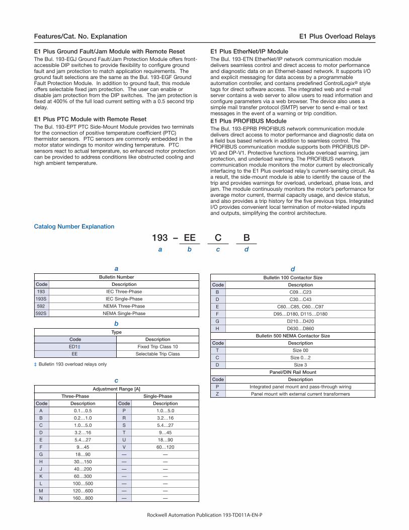
Catalog Number Explanation
193 – EE C Ba b c d
aBulletin Number
Code Description
193 IEC Three-Phase
193S IEC Single-Phase
592 NEMA Three-Phase
592S NEMA Single-Phase
bType
Code Description
ED1‡ Fixed Trip Class 10
EE Selectable Trip Class
‡ Bulletin 193 overload relays only
cAdjustment Range [A]
Three-Phase Single-Phase
Code Description Code Description
A 0.1…0.5 P 1.0…5.0
B 0.2…1.0 R 3.2…16
C 1.0…5.0 S 5.4…27
D 3.2…16 T 9…45
E 5.4…27 U 18…90
F 9…45 V 60…120
G 18…90 — —
H 30…150 — —
J 40…200 — —
K 60…300 — —
L 100…500 — —
M 120…600 — —
N 160…800 — —
dBulletin 100 Contactor Size
Code Description
B C09…C23
D C30…C43
E C60…C85, C60…C97
F D95…D180, D115…D180
G D210…D420
H D630…D860
Bulletin 500 NEMA Contactor Size
Code Description
T Size 00
C Size 0…2
D Size 3
Panel/DIN Rail Mount
Code Description
P Integrated panel mount and pass-through wiring
Z Panel mount with external current transformers
5Rockwell Automation Publication 193-TD011A-EN-P
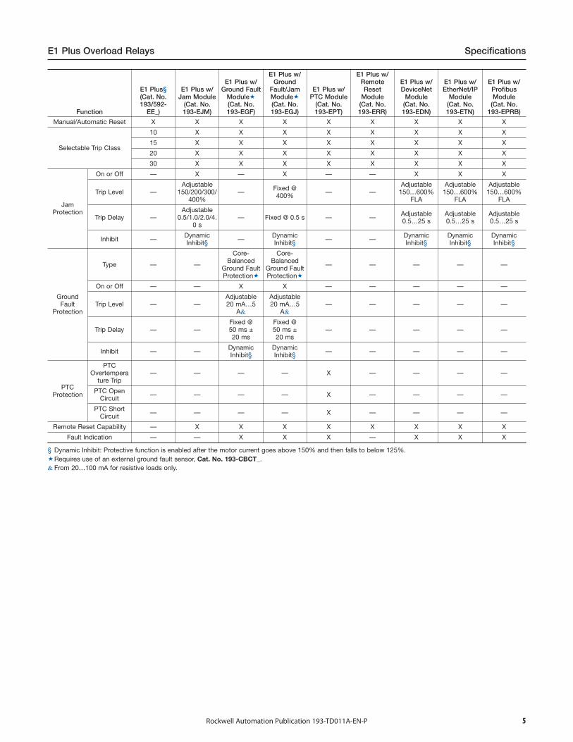
E1 Plus Overload Relays Specifications
Function
E1 Plus§(Cat. No.193/592-
EE_)
E1 Plus w/Jam Module
(Cat. No.193-EJM)
E1 Plus w/Ground Fault
Module�(Cat. No.193-EGF)
E1 Plus w/Ground
Fault/JamModule�(Cat. No.193-EGJ)
E1 Plus w/PTC Module
(Cat. No.193-EPT)
E1 Plus w/RemoteReset
Module(Cat. No.193-ERR)
E1 Plus w/DeviceNet
Module(Cat. No.193-EDN)
E1 Plus w/EtherNet/IP
Module(Cat. No.193-ETN)
E1 Plus w/ProfibusModule
(Cat. No.193-EPRB)
Manual/Automatic Reset X X X X X X X X X
Selectable Trip Class
10 X X X X X X X X
15 X X X X X X X X
20 X X X X X X X X
30 X X X X X X X X
JamProtection
On or Off — X — X — — X X X
Trip Level —Adjustable
150/200/300/400%
— Fixed @400% — —
Adjustable150…600%
FLA
Adjustable150…600%
FLA
Adjustable150…600%
FLA
Trip Delay —Adjustable
0.5/1.0/2.0/4.0 s
— Fixed @ 0.5 s — — Adjustable0.5…25 s
Adjustable0.5…25 s
Adjustable0.5…25 s
Inhibit — DynamicInhibit§ — Dynamic
Inhibit§ — — DynamicInhibit§
DynamicInhibit§
DynamicInhibit§
GroundFault
Protection
Type — —
Core-Balanced
Ground FaultProtection�
Core-Balanced
Ground FaultProtection�
— — — — —
On or Off — — X X — — — — —
Trip Level — —Adjustable20 mA…5
A&
Adjustable20 mA…5
A&— — — — —
Trip Delay — —Fixed @50 ms ±20 ms
Fixed @50 ms ±20 ms
— — — — —
Inhibit — — DynamicInhibit§
DynamicInhibit§ — — — — —
PTCProtection
PTCOvertempera
ture Trip— — — — X — — — —
PTC OpenCircuit — — — — X — — — —
PTC ShortCircuit — — — — X — — — —
Remote Reset Capability — X X X X X X X X
Fault Indication — — X X X — X X X
§ Dynamic Inhibit: Protective function is enabled after the motor current goes above 150% and then falls to below 125%.�Requires use of an external ground fault sensor, Cat. No. 193-CBCT_.& From 20…100 mA for resistive loads only.
6 Rockwell Automation Publication 193-TD011A-EN-P
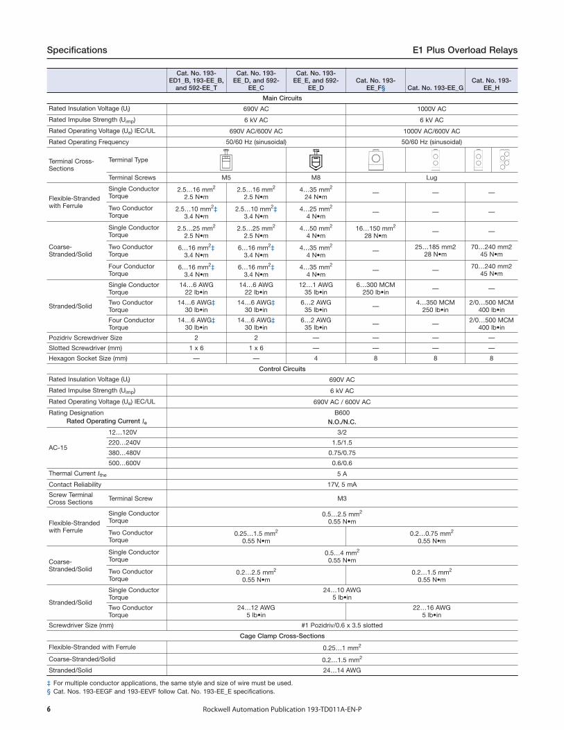
Specifications E1 Plus Overload Relays
Cat. No. 193-ED1_B, 193-EE_B,
and 592-EE_T
Cat. No. 193-EE_D, and 592-
EE_C
Cat. No. 193-EE_E, and 592-
EE_DCat. No. 193-
EE_F§ Cat. No. 193-EE_GCat. No. 193-
EE_H
Main Circuits
Rated Insulation Voltage (Ui) 690V AC 1000V AC
Rated Impulse Strength (Uimp) 6 kV AC 6 kV AC
Rated Operating Voltage (Ue) IEC/UL 690V AC/600V AC 1000V AC/600V AC
Rated Operating Frequency 50/60 Hz (sinusoidal) 50/60 Hz (sinusoidal)
Terminal Cross-Sections
Terminal Type
Terminal Screws M5 M8 Lug
Flexible-Strandedwith Ferrule
Single ConductorTorque
2.5…16 mm2
2.5 N•m2.5…16 mm2
2.5 N•m4…35 mm2
24 N•m— — —
Two ConductorTorque
2.5…10 mm2‡3.4 N•m
2.5…10 mm2‡3.4 N•m
4…25 mm2
4 N•m— — —
Coarse-Stranded/Solid
Single ConductorTorque
2.5…25 mm2
2.5 N•m2.5…25 mm2
2.5 N•m4…50 mm2
4 N•m16…150 mm2
28 N•m— —
Two ConductorTorque
6…16 mm2‡3.4 N•m
6…16 mm2‡3.4 N•m
4…35 mm2
4 N•m— 25…185 mm2
28 N•m70…240 mm2
45 N•m
Four ConductorTorque
6…16 mm2‡3.4 N•m
6…16 mm2‡3.4 N•m
4…35 mm2
4 N•m— — 70…240 mm2
45 N•m
Stranded/Solid
Single ConductorTorque
14…6 AWG22 lb•in
14…6 AWG22 lb•in
12…1 AWG35 lb•in
6…300 MCM250 lb•in — —
Two ConductorTorque
14…6 AWG‡30 lb•in
14…6 AWG‡30 lb•in
6…2 AWG35 lb•in — 4…350 MCM
250 lb•in2/0…500 MCM
400 lb•in
Four ConductorTorque
14…6 AWG‡30 lb•in
14…6 AWG‡30 lb•in
6…2 AWG35 lb•in — — 2/0…500 MCM
400 lb•in
Pozidriv Screwdriver Size 2 2 — — — —
Slotted Screwdriver (mm) 1 x 6 1 x 6 — — — —
Hexagon Socket Size (mm) — — 4 8 8 8
Control Circuits
Rated Insulation Voltage (Ui) 690V AC
Rated Impulse Strength (Uimp) 6 kV AC
Rated Operating Voltage (Ue) IEC/UL 690V AC / 600V AC
Rating Designation B600Rated Operating Current Ie N.O./N.C.
AC-15
12…120V 3/2
220…240V 1.5/1.5
380…480V 0.75/0.75
500…600V 0.6/0.6
Thermal Current Ithe 5 A
Contact Reliability 17V, 5 mA
Screw TerminalCross Sections Terminal Screw M3
Flexible-Strandedwith Ferrule
Single ConductorTorque
0.5…2.5 mm2
0.55 N•m
Two ConductorTorque
0.25…1.5 mm2
0.55 N•m0.2…0.75 mm2
0.55 N•m
Coarse-Stranded/Solid
Single Conductor Torque
0.5…4 mm2
0.55 N•m
Two ConductorTorque
0.2…2.5 mm2
0.55 N•m0.2…1.5 mm2
0.55 N•m
Stranded/Solid
Single ConductorTorque
24…10 AWG5 lb•in
Two ConductorTorque
24…12 AWG5 lb•in
22…16 AWG5 lb•in
Screwdriver Size (mm) #1 Pozidriv/0.6 x 3.5 slotted
Cage Clamp Cross-Sections
Flexible-Stranded with Ferrule 0.25…1 mm2
Coarse-Stranded/Solid 0.2…1.5 mm2
Stranded/Solid 24…14 AWG
‡ For multiple conductor applications, the same style and size of wire must be used.§ Cat. Nos. 193-EEGF and 193-EEVF follow Cat. No. 193-EE_E specifications.
7Rockwell Automation Publication 193-TD011A-EN-P
E1 Plus Overload Relays Specifications
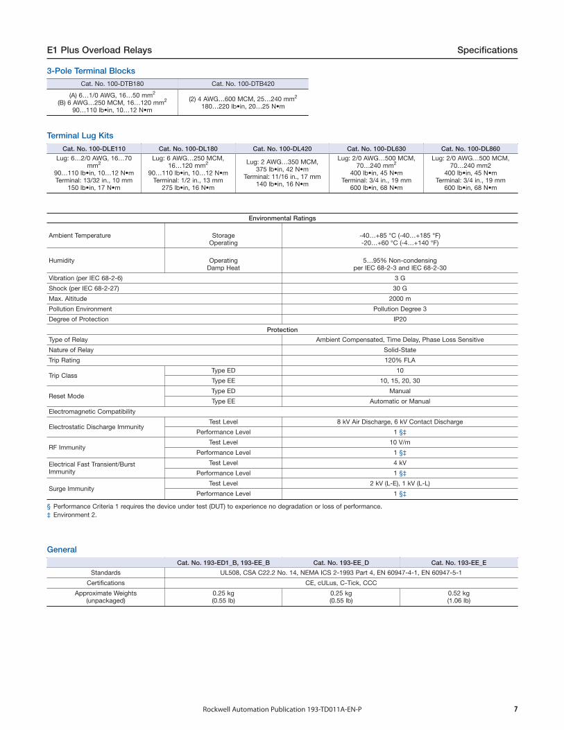
3-Pole Terminal Blocks
Terminal Lug Kits
General
Cat. No. 100-DTB180 Cat. No. 100-DTB420
(A) 6…1/0 AWG, 16…50 mm2
(B) 6 AWG…250 MCM, 16…120 mm2
90…110 lb•in, 10…12 N•m
(2) 4 AWG…600 MCM, 25…240 mm2
180…220 lb•in, 20…25 N•m
Cat. No. 100-DLE110 Cat. No. 100-DL180 Cat. No. 100-DL420 Cat. No. 100-DL630 Cat. No. 100-DL860Lug: 6…2/0 AWG, 16…70
mm2
90…110 lb•in, 10…12 N•mTerminal: 13/32 in., 10 mm
150 lb•in, 17 N•m
Lug: 6 AWG…250 MCM,16…120 mm2
90…110 lb•in, 10…12 N•mTerminal: 1/2 in., 13 mm
275 lb•in, 16 N•m
Lug: 2 AWG…350 MCM,375 lb•in, 42 N•m
Terminal: 11/16 in., 17 mm140 lb•in, 16 N•m
Lug: 2/0 AWG…500 MCM,70…240 mm2
400 lb•in, 45 N•mTerminal: 3/4 in., 19 mm
600 lb•in, 68 N•m
Lug: 2/0 AWG…500 MCM,70…240 mm2
400 lb•in, 45 N•mTerminal: 3/4 in., 19 mm
600 lb•in, 68 N•m
Environmental Ratings
Ambient Temperature StorageOperating
-40…+85 °C (-40…+185 °F)-20…+60 °C (-4…+140 °F)
Humidity OperatingDamp Heat
5…95% Non-condensingper IEC 68-2-3 and IEC 68-2-30
Vibration (per IEC 68-2-6) 3 G
Shock (per IEC 68-2-27) 30 G
Max. Altitude 2000 m
Pollution Environment Pollution Degree 3
Degree of Protection IP20
Protection
Type of Relay Ambient Compensated, Time Delay, Phase Loss Sensitive
Nature of Relay Solid-State
Trip Rating 120% FLA
Trip ClassType ED 10
Type EE 10, 15, 20, 30
Reset ModeType ED Manual
Type EE Automatic or Manual
Electromagnetic Compatibility
Electrostatic Discharge ImmunityTest Level 8 kV Air Discharge, 6 kV Contact Discharge
Performance Level 1 §‡
RF ImmunityTest Level 10 V/m
Performance Level 1 §‡
Electrical Fast Transient/BurstImmunity
Test Level 4 kV
Performance Level 1 §‡
Surge ImmunityTest Level 2 kV (L-E), 1 kV (L-L)
Performance Level 1 §‡
§ Performance Criteria 1 requires the device under test (DUT) to experience no degradation or loss of performance.‡ Environment 2.
Cat. No. 193-ED1_B, 193-EE_B Cat. No. 193-EE_D Cat. No. 193-EE_E
Standards UL508, CSA C22.2 No. 14, NEMA ICS 2-1993 Part 4, EN 60947-4-1, EN 60947-5-1
Certifications CE, cULus, C-Tick, CCC
Approximate Weights(unpackaged)
0.25 kg(0.55 lb)
0.25 kg(0.55 lb)
0.52 kg(1.06 lb)
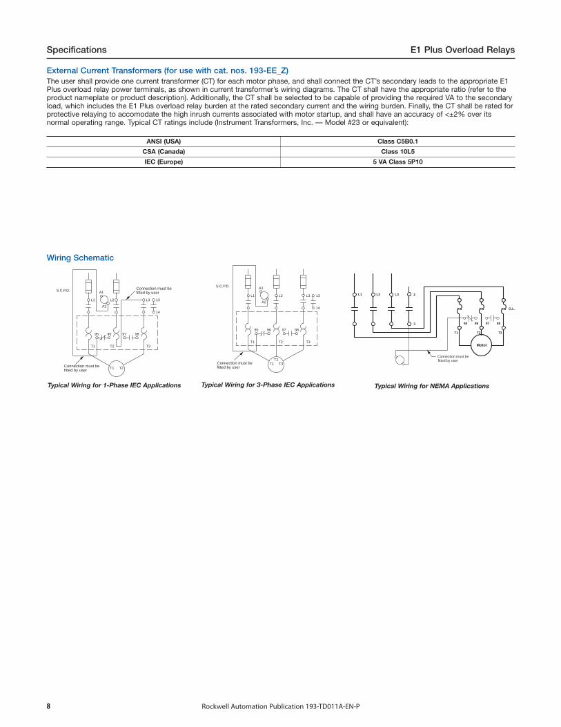
Wiring Schematic
ANSI (USA) Class C5B0.1
CSA (Canada) Class 10L5
IEC (Europe) 5 VA Class 5P10
95
L2 L3 13L1
14
A1
A2
T2 T3T1
96 97 98
T1 T2
S.C.P.D. Connection must befitted by user
Connection must befitted by user
Typical Wiring for 1-Phase IEC Applications
95
L2 L3 13L1
14
A1
A2
T2 T3T1
96 97 98
T1 T3T2
S.C.P.D.
Connection must befitted by user
Typical Wiring for 3-Phase IEC Applications
Connection must befitted by user
L3L2L1
T3T2T1
Motor
3
2
O.L.
9695 9897
Typical Wiring for NEMA Applications
Specifications E1 Plus Overload Relays
Rockwell Automation Publication 193-TD011A-EN-P8
External Current Transformers (for use with cat. nos. 193-EE_Z)The user shall provide one current transformer (CT) for each motor phase, and shall connect the CT’s secondary leads to the appropriate E1Plus overload relay power terminals, as shown in current transformer’s wiring diagrams. The CT shall have the appropriate ratio (refer to theproduct nameplate or product description). Additionally, the CT shall be selected to be capable of providing the required VA to the secondaryload, which includes the E1 Plus overload relay burden at the rated secondary current and the wiring burden. Finally, the CT shall be rated forprotective relaying to accomodate the high inrush currents associated with motor startup, and shall have an accuracy of <±2% over itsnormal operating range. Typical CT ratings include (Instrument Transformers, Inc. — Model #23 or equivalent):
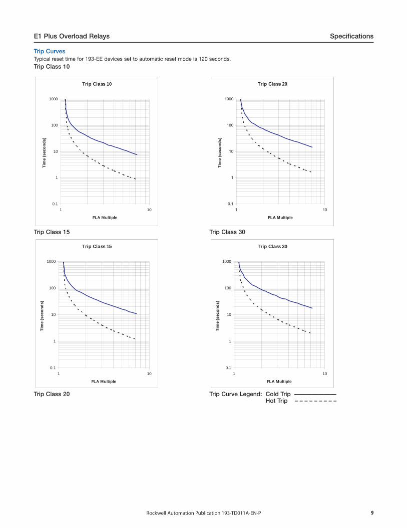
Trip Class 10
0.1
1
10
100
1000
1 10
FLA Multiple
Tim
e (
seco
nd
s)
Trip Class 15
Trip Class 15
0.1
1
10
100
1000
1 10
FLA Multiple
Tim
e (
seco
nd
s)
Trip Class 20
Trip Class 20
0.1
1
10
100
1000
1 10
FLA MultipleT
ime (
seco
nd
s)
Trip Class 30
Trip Class 30
0.1
1
10
100
1000
1 10
FLA Multiple
Tim
e (
seco
nd
s)
Trip Curve Legend: Cold Trip ———————Hot Trip – – – – – – – – –
Trip CurvesTypical reset time for 193-EE devices set to automatic reset mode is 120 seconds.
Trip Class 10
E1 Plus Overload Relays Specifications
Rockwell Automation Publication 193-TD011A-EN-P 9
10 Rockwell Automation Publication 193-TD011A-EN-P
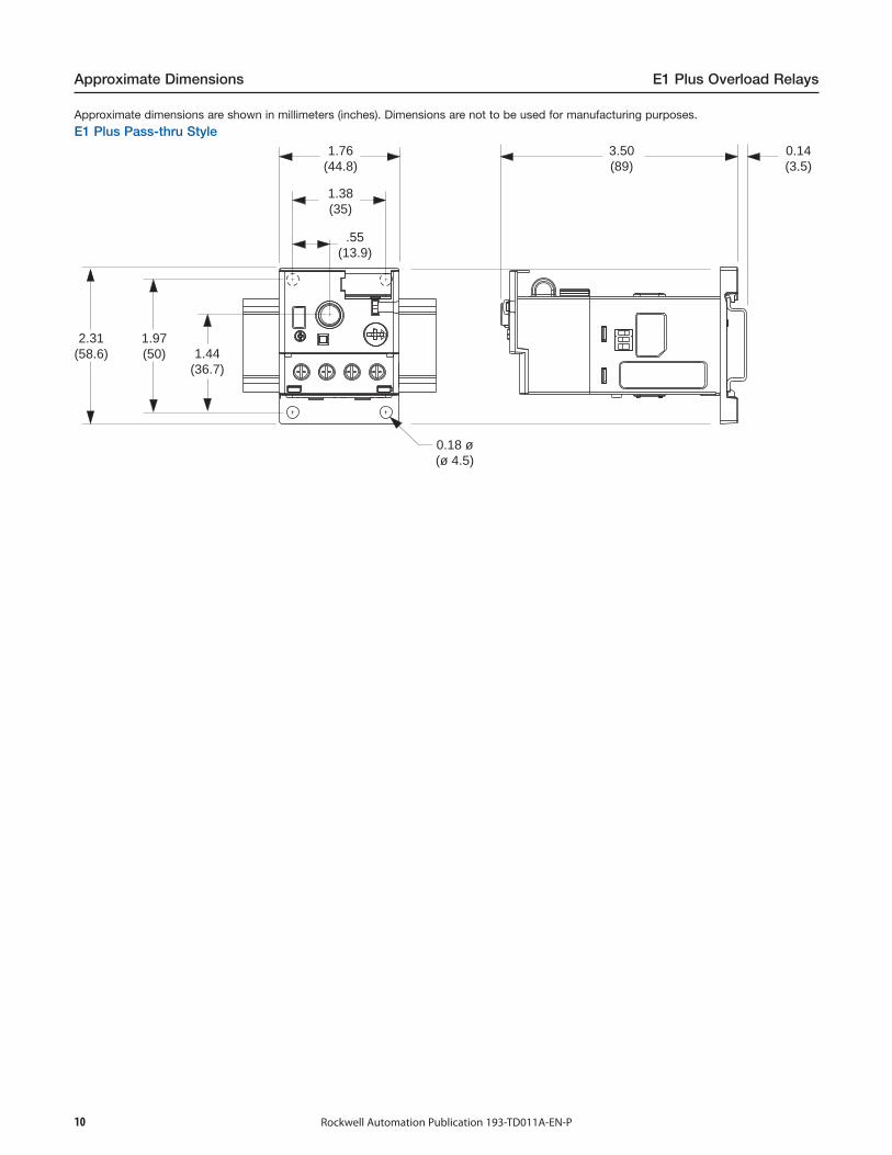
Approximate Dimensions E1 Plus Overload Relays
Approximate dimensions are shown in millimeters (inches). Dimensions are not to be used for manufacturing purposes.
E1 Plus Pass-thru Style1.76
(44.8)
1.38(35)
.55(13.9)
0.18 ø(ø 4.5)
0.14(3.5)
3.50(89)
2.31(58.6)
1.97(50) 1.44
(36.7)
11Rockwell Automation Publication 193-TD011A-EN-P
E1 Plus Overload Relays Approximate Dimensions
Approximate dimensions are shown in millimeters (inches). Dimensions are not to be used for manufacturing purposes.
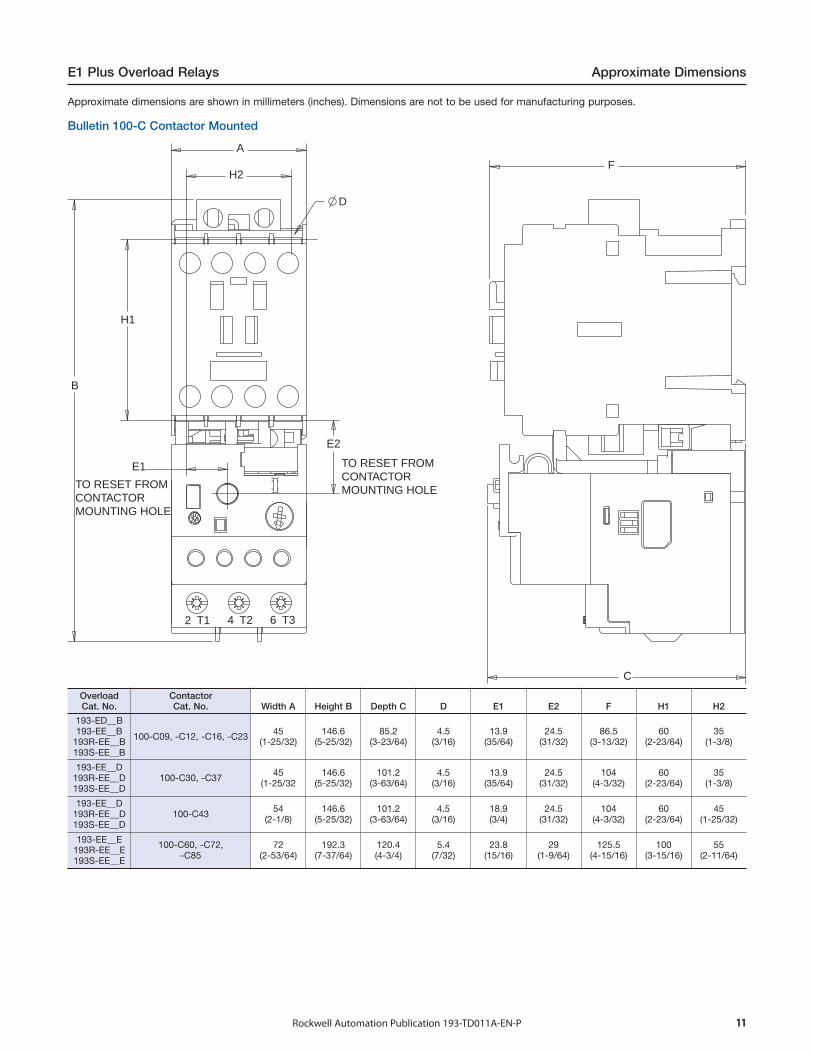
Bulletin 100-C Contactor Mounted
A
D
H2
E2
E1
H1
B
TO RESET FROM CONTACTOR MOUNTING HOLETO RESET FROM
CONTACTOR MOUNTING HOLE
2 T1 4 T2 6 T3
F
C
OverloadCat. No.
ContactorCat. No. Width A Height B Depth C D E1 E2 F H1 H2
193-ED__B193-EE__B
193R-EE__B193S-EE__B
100-C09, -C12, -C16, -C23 45(1-25/32)
146.6(5-25/32)
85.2(3-23/64)
4.5(3/16)
13.9(35/64)
24.5(31/32)
86.5(3-13/32)
60(2-23/64)
35(1-3/8)
193-EE__D193R-EE__D193S-EE__D
100-C30, -C37 45(1-25/32
146.6(5-25/32)
101.2(3-63/64)
4.5(3/16)
13.9(35/64)
24.5(31/32)
104(4-3/32)
60(2-23/64)
35(1-3/8)
193-EE__D193R-EE__D193S-EE__D
100-C43 54(2-1/8)
146.6(5-25/32)
101.2(3-63/64)
4.5(3/16)
18.9(3/4)
24.5(31/32)
104(4-3/32)
60(2-23/64)
45(1-25/32)
193-EE__E193R-EE__E193S-EE__E
100-C60, -C72,-C85
72(2-53/64)
192.3(7-37/64)
120.4(4-3/4)
5.4(7/32)
23.8(15/16)
29(1-9/64)
125.5(4-15/16)
100(3-15/16)
55(2-11/64)
12 Rockwell Automation Publication 193-TD011A-EN-P
Approximate Dimensions E1 Plus Overload Relays
BB1
F
G
E1
C
D
A
E2
J
K
øM
H
CL
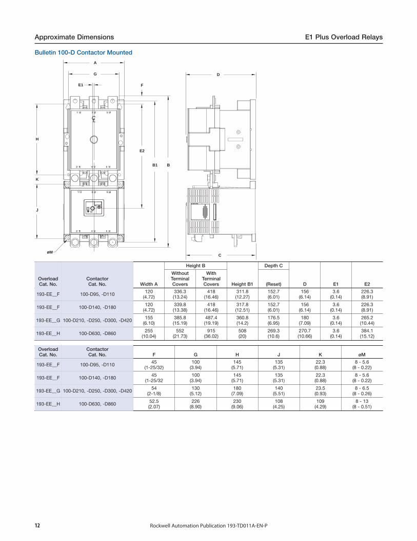
OverloadCat. No.
ContactorCat. No. Width A
Height B
Height B1
Depth C
D E1 E2
WithoutTerminalCovers
WithTerminalCovers (Reset)
193-EE__F 100-D95, -D110 120(4.72)
336.3(13.24)
418(16.46)
311.8(12.27)
152.7(6.01)
156(6.14)
3.6(0.14)
226.3(8.91)
193-EE__F 100-D140, -D180 120(4.72)
339.8(13.38)
418(16.46)
317.8(12.51)
152.7(6.01)
156(6.14)
3.6(0.14)
226.3(8.91)
193-EE__G 100-D210, -D250, -D300, -D420 155(6.10)
385.8(15.19)
487.4(19.19)
360.8(14.2)
176.5(6.95)
180(7.09)
3.6(0.14)
265.2(10.44)
193-EE__H 100-D630, -D860 255(10.04)
552(21.73)
915(36.02)
508(20)
269.3(10.6)
270.7(10.66)
3.6(0.14)
384.1(15.12)
OverloadCat. No.
ContactorCat. No. F G H J K øM
193-EE__F 100-D95, -D110 45(1-25/32)
100(3.94)
145(5.71)
135(5.31)
22.3(0.88)
8 - 5.6(8 - 0.22)
193-EE__F 100-D140, -D180 45(1-25/32
100(3.94)
145(5.71)
135(5.31)
22.3(0.88)
8 - 5.6(8 - 0.22)
193-EE__G 100-D210, -D250, -D300, -D420 54(2-1/8)
130(5.12)
180(7.09)
140(5.51)
23.5(0.93)
8 - 6.5(8 - 0.26)
193-EE__H 100-D630, -D860 52.5(2.07)
226(8.90)
230(9.06)
108(4.25)
109(4.29)
8 - 13(8 - 0.51)
Bulletin 100-D Contactor Mounted
13Rockwell Automation Publication 193-TD011A-EN-P
E1 Plus Overload Relays Approximate Dimensions
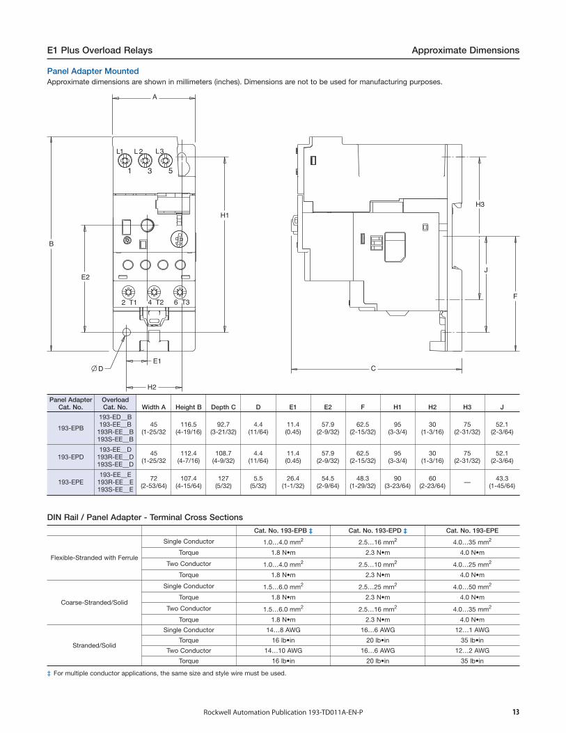
Panel Adapter MountedApproximate dimensions are shown in millimeters (inches). Dimensions are not to be used for manufacturing purposes.
Panel AdapterCat. No.
OverloadCat. No. Width A Height B Depth C D E1 E2 F H1 H2 H3 J
193-EPB
193-ED__B193-EE__B
193R-EE__B193S-EE__B
45(1-25/32
116.5(4-19/16)
92.7(3-21/32)
4.4(11/64)
11.4(0.45)
57.9(2-9/32)
62.5(2-15/32)
95(3-3/4)
30(1-3/16)
75(2-31/32)
52.1(2-3/64)
193-EPD193-EE__D
193R-EE__D193S-EE__D
45(1-25/32
112.4(4-7/16)
108.7(4-9/32)
4.4(11/64)
11.4(0.45)
57.9(2-9/32)
62.5(2-15/32)
95(3-3/4)
30(1-3/16)
75(2-31/32)
52.1(2-3/64)
193-EPE193-EE__E
193R-EE__E193S-EE__E
72(2-53/64)
107.4(4-15/64)
127(5/32)
5.5(5/32)
26.4(1-1/32)
54.5(2-9/64)
48.3(1-29/32)
90(3-23/64)
60(2-23/64) — 43.3
(1-45/64)
DIN Rail / Panel Adapter - Terminal Cross Sections
Cat. No. 193-EPB ‡ Cat. No. 193-EPD ‡ Cat. No. 193-EPE
Flexible-Stranded with Ferrule
Single Conductor 1.0…4.0 mm2 2.5…16 mm2 4.0…35 mm2
Torque 1.8 N•m 2.3 N•m 4.0 N•m
Two Conductor 1.0…4.0 mm2 2.5…10 mm2 4.0…25 mm2
Torque 1.8 N•m 2.3 N•m 4.0 N•m
Coarse-Stranded/Solid
Single Conductor 1.5…6.0 mm2 2.5…25 mm2 4.0…50 mm2
Torque 1.8 N•m 2.3 N•m 4.0 N•m
Two Conductor 1.5…6.0 mm2 2.5…16 mm2 4.0…35 mm2
Torque 1.8 N•m 2.3 N•m 4.0 N•m
Stranded/Solid
Single Conductor 14…8 AWG 16…6 AWG 12…1 AWG
Torque 16 lb•in 20 lb•in 35 lb•in
Two Conductor 14…10 AWG 16…6 AWG 12…2 AWG
Torque 16 lb•in 20 lb•in 35 lb•in
‡ For multiple conductor applications, the same size and style wire must be used.

Allen-Bradley, Rockwell Software, Rockwell Automation, and LISTEN. THINK. SOLVE are trademarks of Rockwell Automation, Inc.
Trademarks not belonging to Rockwell Automation are property of their respective companies.
Publication 193-TD011A-EN-P - August 2014 Copyright © 2014 Rockwell Automation, Inc. All rights reserved. Printed in the U.S.A.
Important User Information
Read this document and the documents listed in the additional resources section about installation, configuration, and operation of this equipment before you install, configure, operate, or maintain this product. Users are required to familiarize themselves with installation and wiring instructions in addition to requirements of all applicable codes, laws, and standards.
Activities including installation, adjustments, putting into service, use, assembly, disassembly, and maintenance are required to be carried out by suitably trained personnel in accordance with applicable code of practice.
If this equipment is used in a manner not specified by the manufacturer, the protection provided by the equipment may be impaired.
In no event will Rockwell Automation, Inc. be responsible or liable for indirect or consequential damages resulting from the use or application of this equipment.
The examples and diagrams in this manual are included solely for illustrative purposes. Because of the many variables and requirements associated with any particular installation, Rockwell Automation, Inc. cannot assume responsibility or liability for actual use based on the examples and diagrams.
No patent liability is assumed by Rockwell Automation, Inc. with respect to use of information, circuits, equipment, or software described in this manual.
Reproduction of the contents of this manual, in whole or in part, without written permission of Rockwell Automation, Inc., is prohibited.
Documentation Feedback
Your comments will help us serve your documentation needs better. If you have any suggestions on how to improve this document, complete this form, publication RA-DU002, available at http://www.rockwellautomation.com/literature/.
Rockwell Otomasyon Ticaret A.Ş., Kar Plaza İş Merkezi E Blok Kat:6 34752 İçerenköy, İstanbul, Tel: +90 (216) 5698400


![Bulletin 309 AC Starters - · PDF fileBulletin 309 AC Starters %XOOHWLQ ²1(0$$&6WDUWHUV 1(0$VL]HV « Cost saving design E1 Plus electronic overload relays Compact size Bulletin 309](https://img.pdfslide.us/doc/110x75/5ab1d35c7f8b9a1d168d19f6/bulletin-309-ac-starters-309-ac-starters-xoohwlq-106wduwhuv-10vlhv-cost.jpg)