Embed Size (px)
Citation preview
[PROJECT NUMBER] [PROJECT NAME] [DATE] [PROJECT LOCATION]
Electronic Overload Relay Rockwell Automation 193-SR002-EN-P 1
ROCKWELL AUTOMATION PROCUREMENT SPECIFICATION
PROCUREMENT SPECIFICATION
E1 Plus Electronic Overload Relay
NOTICE: The specification guidelines in this document are intended to aid in the specification of products. Specific installations have specific requirements, and Rockwell Automation does not recommend or intend any specific application based solely upon the guidelines provided here. Because of the variety of uses for this information, the user of, and those responsible for applying this information, are responsible for ensuring the acceptability of each application and appropriate use of the guidelines. In no event will Rockwell Automation be liable for misuse, misapplication or reliance on these guidelines in connection with any specific application. Rockwell Automation also disclaims indirect or consequential damages resulting from the use or application of this information. Note: To download or view a .doc file version of this procurement specification, please visit: www.rockwellautomation.com/industries/procurement-specifications
[PROJECT NUMBER] [PROJECT NAME] [DATE] [PROJECT LOCATION]
Rockwell Automation Electronic Overload Relay 2 193-SR002-EN-P
TABLE OF CONTENTS
PART 1 GENERAL ..................................................................................................................... 3
1.01 QUALIFICATIONS ....................................................................................................... 3 1.02 REFERENCES ............................................................................................................ 3 1.03 ENVIRONMENTAL REQUIREMENTS .......................................................................... 4 1.04 PRE-MANUFACTURE SUBMITTALS ........................................................................... 4 1.05 FINAL SUBMITTALS .................................................................................................... 4
PART 2 PRODUCTS .................................................................................................................. 5 2.01 RATINGS .................................................................................................................... 5 2.02 CONSTRUCTION ........................................................................................................ 6 2.03 OVERLOAD RELAY ..................................................................................................... 6 2.04 OPTIONAL PROTECTIVE, REMOTE RESET AND COMMUNICATION MODULES (LIMIT 1) ................................................................................................................................. 7 2.05 ACCESSORIES ......................................................................................................... 12
PART 3 EXECUTION ................................................................................................................ 13 3.01 DELIVERY, STORAGE, AND HANDLING ................................................................... 13 3.02 INSTALLATION ......................................................................................................... 13 3.03 SPARE MATERIALS .................................................................................................. 13 3.04 WARRANTY .............................................................................................................. 13
[PROJECT NUMBER] [PROJECT NAME] [DATE] [PROJECT LOCATION]
Electronic Overload Relay Rockwell Automation 193-SR002-EN-P 3
PART 1 GENERAL
1.01 QUALIFICATIONS
A. Manufacturer
1. The manufacturer shall have a minimum of 25 years of experience in the manufacture of electronic overload relays.
2. The approved manufacturers are:
a) Rockwell Automation Allen-Bradley b) Substitutions: None permitted
B. Support
1. The manufacturer shall maintain factory trained and authorized service facilities within 100 miles of the project and shall have a demonstrated record of service for at least the previous ten years.
2. Support personnel are to be direct employees of the manufacturer and be available 24 hours per day through a toll-free number.
3. The manufacturer shall provide all required start-up and training services. 4. The approved manufacturers are:
a) Rockwell Automation Customer Support & Maintenance b) Substitutions: None permitted
C. Certification
1. To ensure all quality and corrective action procedures are documented and implemented, all manufacturing locations shall be certified to the ISO-9001 Series of Quality Standards.
2. Third-party manufacturers and brand labeling shall not be allowed.
1.02 REFERENCES
A. The electronic overload relay shall be certified:
1. CE 2. cULus Listed 3. C-Tick 4. CCC
B. The following standards shall be met:
1. EN 60947-4-1 2. EN 60947-5-1 3. UL508 4. CSA C22.2 No. 14 (cUL) 5. NEMA ICS 2-1993 Part 4
C. Terminal markings shall comply with CENELEC and EN 50012.
[PROJECT NUMBER] [PROJECT NAME] [DATE] [PROJECT LOCATION]
Rockwell Automation Electronic Overload Relay 4 193-SR002-EN-P
1.03 ENVIRONMENTAL REQUIREMENTS
A. The supplier shall confirm specified service conditions during and after installation of products.
B. The supplier shall maintain the area free of dirt and dust during and after installation of products.
1.04 PRE-MANUFACTURE SUBMITTALS
A. Refer to Section _________ for submittal procedures. B. Product Data
1. Publications on electronic overload relay. 2. Data sheets on the expansion module and accessories, when applicable.
C. Specification Response
1. Detailed response to this specification showing where in the literature each requirement is satisfied.
2. Clearly identified clarifications and exceptions.
D. Installation Instructions
1. A copy of the manufacturer’s installation instructions, including receiving, handling and storage instructions.
E. Testing and Test Reports
1. Testing per manufacturer’s standard.
2. A copy of the test reports, if available, shall be provided as part of the final documentation.
1.05 FINAL SUBMITTALS
A. Refer to Section ________ for procedure on submittal of final documentation. B. Supplier Certification
1. The supplier shall provide certification that the electronic overload relay has been installed in accordance with the manufacturer’s instructions.
2. The supplier shall provide certification that the electronic overload relay settings have been properly adjusted.
C. Final Drawings
1. The manufacturer shall provide final drawings reflecting the “As-Shipped” state of the installed equipment.
2. Manufacturer drawings shall be provided in DWG format. 3. Manufacturer drawings do not need to be stamped if a drawing schedule is provided
that lists the drawing numbers, revision levels, and status of drawings (Preliminary, Approval, Final, etc.)
4. The supplier shall be responsible for making any changes to the “As-Shipped” drawings from the manufacturer to reflect any field modifications.
[PROJECT NUMBER] [PROJECT NAME] [DATE] [PROJECT LOCATION]
Electronic Overload Relay Rockwell Automation 193-SR002-EN-P 5
D. Maintenance Data
1. Electronic overload relay installation instructions and User Manual. 2. Field service report from start-up service.
3. Name and phone number for a local distributor for the spare parts.
PART 2 PRODUCTS
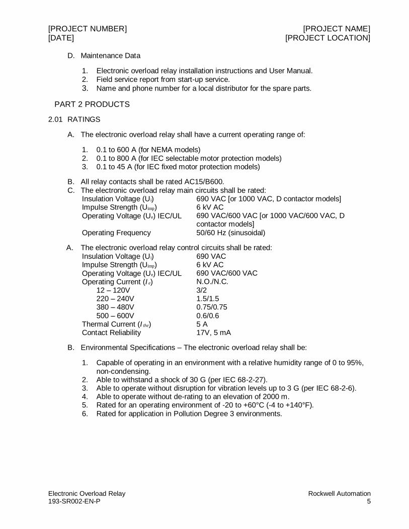
2.01 RATINGS
A. The electronic overload relay shall have a current operating range of:
1. 0.1 to 600 A (for NEMA models) 2. 0.1 to 800 A (for IEC selectable motor protection models) 3. 0.1 to 45 A (for IEC fixed motor protection models)
B. All relay contacts shall be rated AC15/B600. C. The electronic overload relay main circuits shall be rated:
Insulation Voltage (Ui) Impulse Strength (Uimp) Operating Voltage (Ue) IEC/UL Operating Frequency
690 VAC [or 1000 VAC, D contactor models] 6 kV AC 690 VAC/600 VAC [or 1000 VAC/600 VAC, D contactor models] 50/60 Hz (sinusoidal)
A. The electronic overload relay control circuits shall be rated: Insulation Voltage (Ui) Impulse Strength (Uimp) Operating Voltage (Ue) IEC/UL Operating Current (I e)
690 VAC 6 kV AC 690 VAC/600 VAC N.O./N.C.
12 – 120V 3/2 220 – 240V 1.5/1.5 380 – 480V 0.75/0.75 500 – 600V 0.6/0.6 Thermal Current (I the) 5 A Contact Reliability 17V, 5 mA
B. Environmental Specifications – The electronic overload relay shall be:
1. Capable of operating in an environment with a relative humidity range of 0 to 95%, non-condensing.
2. Able to withstand a shock of 30 G (per IEC 68-2-27). 3. Able to operate without disruption for vibration levels up to 3 G (per IEC 68-2-6). 4. Able to operate without de-rating to an elevation of 2000 m. 5. Rated for an operating environment of -20 to +60°C (-4 to +140°F). 6. Rated for application in Pollution Degree 3 environments.
[PROJECT NUMBER] [PROJECT NAME] [DATE] [PROJECT LOCATION]
Rockwell Automation Electronic Overload Relay 6 193-SR002-EN-P
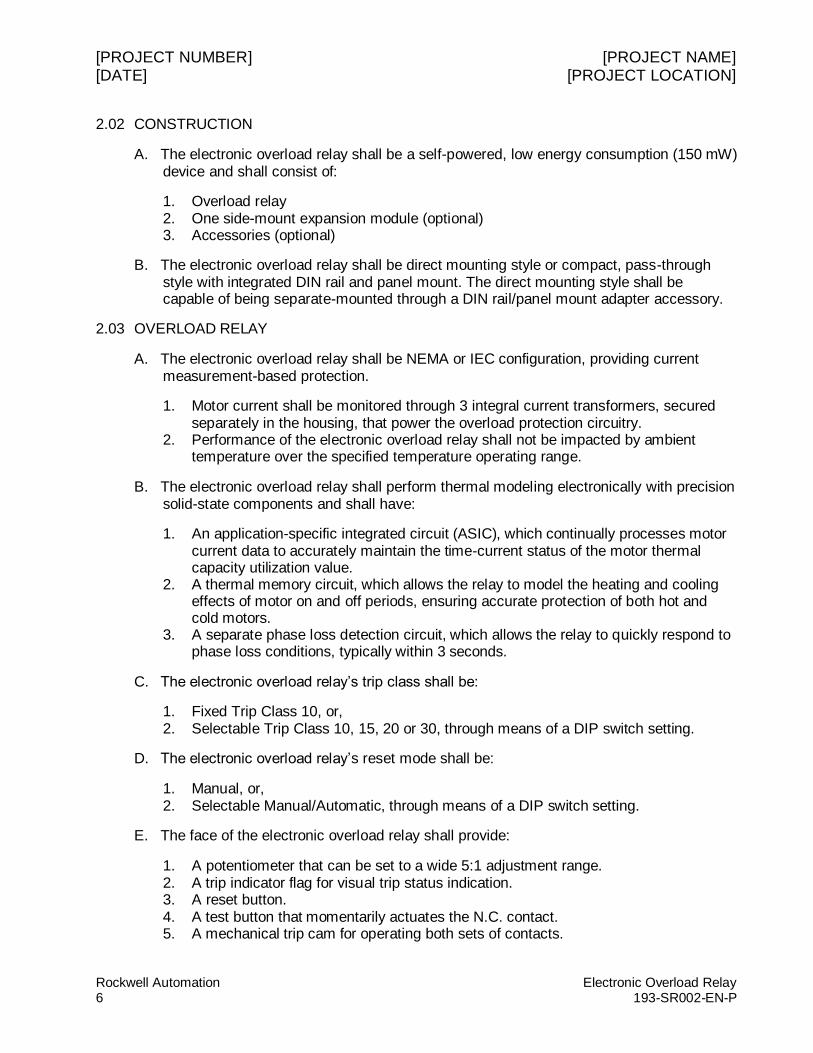
2.02 CONSTRUCTION
A. The electronic overload relay shall be a self-powered, low energy consumption (150 mW) device and shall consist of:
1. Overload relay 2. One side-mount expansion module (optional) 3. Accessories (optional)
B. The electronic overload relay shall be direct mounting style or compact, pass-through style with integrated DIN rail and panel mount. The direct mounting style shall be capable of being separate-mounted through a DIN rail/panel mount adapter accessory.
2.03 OVERLOAD RELAY
A. The electronic overload relay shall be NEMA or IEC configuration, providing current measurement-based protection.
1. Motor current shall be monitored through 3 integral current transformers, secured separately in the housing, that power the overload protection circuitry.
2. Performance of the electronic overload relay shall not be impacted by ambient temperature over the specified temperature operating range.
B. The electronic overload relay shall perform thermal modeling electronically with precision solid-state components and shall have:
1. An application-specific integrated circuit (ASIC), which continually processes motor current data to accurately maintain the time-current status of the motor thermal capacity utilization value.
2. A thermal memory circuit, which allows the relay to model the heating and cooling effects of motor on and off periods, ensuring accurate protection of both hot and cold motors.
3. A separate phase loss detection circuit, which allows the relay to quickly respond to phase loss conditions, typically within 3 seconds.
C. The electronic overload relay’s trip class shall be:
1. Fixed Trip Class 10, or, 2. Selectable Trip Class 10, 15, 20 or 30, through means of a DIP switch setting.
D. The electronic overload relay’s reset mode shall be:
1. Manual, or, 2. Selectable Manual/Automatic, through means of a DIP switch setting.
E. The face of the electronic overload relay shall provide:
1. A potentiometer that can be set to a wide 5:1 adjustment range. 2. A trip indicator flag for visual trip status indication. 3. A reset button. 4. A test button that momentarily actuates the N.C. contact. 5. A mechanical trip cam for operating both sets of contacts.
[PROJECT NUMBER] [PROJECT NAME] [DATE] [PROJECT LOCATION]
Electronic Overload Relay Rockwell Automation 193-SR002-EN-P 7
F. Electrical connections:
1. The electronic overload relay shall work with three-phase or single-phase applications.
2. The electronic overload relay shall be capable of direct connection and mounting to contactors in low voltage applications.
3. The electronic overload relay shall provide 1 N.O. and 1 N.C. isolated auxiliary contacts. The isolated configuration allows them to be applied in circuits operating at different voltage levels and without polarity restrictions.
4. The electronic overload relay shall have line-side over-molded connections. 5. Wiring terminals shall provide IP20 finger protection.
2.04 OPTIONAL PROTECTIVE, REMOTE RESET AND COMMUNICATION MODULES (LIMIT 1)
A. Remote Reset Module
1. Ratings: Insulation Voltage (Ui) Operating Voltage (Ue) Power at Ue
24 VAC 120 VAC 240 VAC Impulse Withstand Voltage
300V 24 to 240 VAC/VDC, 50/60 Hz 0.8 W 0.8 W 1.0 W 2.5 kV
2. The remote reset module shall provide remote reset of the electronic overload relay after a trip occurs.
a) Directly mounts to the left side of the electronic overload relay, adding only 18 mm to the overall width.
b) Electronically interfaces with the electronic overload relay so that all control circuit connections are made at the relay terminals.
B. Jam Protection Module with Remote Reset
1. Ratings: Insulation Voltage (Ui) Operating Voltage (Ue) Power at Ue
24 VAC 120 VAC 240 VAC Impulse Withstand Voltage
300V 24 to 240 VAC/VDC, 50/60 Hz 0.3 W 0.3 W 0.5 W 2.5 kV
2. The jam protection module with remote reset shall provide flexible jam protection.
a) Directly mounts to the left side of the electronic overload relay, adding only 18 mm to the overall width.
b) Electronically interfaces with the electronic overload relay so that all control circuit connections are made at the relay terminals.
3. The jam protection module with remote reset shall provide front-accessible DIP switches that offer jam protection settings to match application requirements.
[PROJECT NUMBER] [PROJECT NAME] [DATE] [PROJECT LOCATION]
Rockwell Automation Electronic Overload Relay 8 193-SR002-EN-P
a) Enabling/disabling of jam protection function and remote reset operation. b) Jam trip level settings at 150%, 200%, 300% and 400% of full load current
setting. c) Trip delay settings of 1/2, 1, 2 and 4 seconds to minimize nuisance tripping.
C. Ground Fault Protection Module with Remote Reset
1. Ratings: Insulation Voltage (Ui) Operating Voltage (Ue) Power at Ue
24 VAC 120 VAC 240 VAC Impulse Withstand Voltage
300V 24 to 240 VAC/VDC, 50/60 Hz 0.8 W 0.8 W 1.0 W 2.5 kV
2. The ground fault protection module with remote reset shall provide flexible ground fault protection.
a) Directly mounts to the left side of the electronic overload relay, adding only 18 mm to the overall width.
b) Electronically interfaces with the electronic overload relay so that all control circuit connections are made at the relay terminals.
3. The ground fault protection module with remote reset shall provide front-accessible DIP switches that offer ground fault protection settings to match application requirements.
a) Enabling/disabling of ground fault protection function and remote reset operation.
b) Ground fault trip level settings in 4 ranges: 20 to 100 mA (resistive loads); 100 to 500 mA; 0.2 to 1 A; 1 to 5 A. Within each range, specific percentages of maximum ground fault can be set.
c) Trip delay fixed at 50 ms ± 20 ms.
D. Ground Fault/Jam Protection Module with Remote Reset
1. Ratings: Insulation Voltage (Ui) Operating Voltage (Ue) Power at Ue
24 VAC 120 VAC 240 VAC Impulse Withstand Voltage
300V 24 to 240 VAC/VDC, 50/60 Hz 0.8 W 0.8 W 1.0 W 2.5 kV
2. The ground fault/jam protection module with remote reset shall provide flexible ground fault and jam protection.
a) Directly mounts to the left side of the electronic overload relay, adding only 18 mm to the overall width.
b) Electronically interfaces with the electronic overload relay so that all control circuit connections are made at the relay terminals.
[PROJECT NUMBER] [PROJECT NAME] [DATE] [PROJECT LOCATION]
Electronic Overload Relay Rockwell Automation 193-SR002-EN-P 9
3. The ground fault/jam protection module with remote reset shall provide front-accessible DIP switches that offer ground fault and jam protection settings to match application requirements.
a) Enabling/disabling of ground fault protection and jam protection functions and remote reset operation.
b) Ground fault trip level settings in 4 ranges: 20 to 100 mA (resistive loads); 100 to 500 mA; 0.2 to 1 A; 1 to 5 A. Within each range, specific percentages of maximum ground fault can be set.
c) Ground fault trip delay fixed at 50 ms ± 20 ms. d) Jam protection fixed at 400% of full load current setting with a 0.5 second trip
delay.
E. PTC Module with Remote Reset
1. Ratings: Insulation Voltage (Ui) Operating Voltage (Ue) Power at Ue
24 VAC 120 VAC 240 VAC Impulse Withstand Voltage
300V 24 to 240 VAC/VDC, 50/60 Hz 0.8 W 0.8 W 1.0 W 2.5 kV
2. The PTC module with remote reset shall provide enhanced motor protection based on actual temperature.
a) Directly mounts to the left side of the electronic overload relay, adding only 18 mm to the overall width.
b) Electronically interfaces with the electronic overload relay so that all control circuit connections are made at the relay terminals.
3. The PTC module with remote reset shall provide 2 terminals for the connection of positive temperature coefficient (PTC) thermistor sensors.
a) PTC sensors shall be able to directly monitor the temperature of motor stator windings.
b) Conditions such as obstructed cooling and high ambient temperature shall be addressed.
F. EtherNet/IP and Protection Module
1. Power Supply Ratings Supply Voltage (Us) 24 VDC Operating Range (Ue) 20.4 to 26.4V Supply Current (I e) 0.11 A Max Surge @ Power-Up 2.5 A Max Power Consumption 2.7 W
2. Output Relay Ratings: Thermal Current (I the) 5 A Insulation Voltage (Ui) 300 VAC
[PROJECT NUMBER] [PROJECT NAME] [DATE] [PROJECT LOCATION]
Rockwell Automation Electronic Overload Relay 10 193-SR002-EN-P
Operating Voltage (Ue) Operating Current (I e) 120 VAC 240V 110 VDC 220 VDC
Minimum Operating Current Designation/Utiliz. Category
240 VAC 3 A 1.5 A 0.25 A 0.1 A 10 mA at 5 VDC B300/AC15
3. The EtherNet/IP and protection module shall provide seamless control and direct access to motor performance and diagnostic data on an Ethernet-based network.
a) Directly mounts to the left side of the electronic overload relay, adding only 22 mm to the overall width.
b) Electronically interfaces with the electronic overload relay so that all control circuit connections are made at the relay terminals.
4. The EtherNet/IP and protection module shall enhance communication.
a) Supports I/O and explicit messaging for data access by a PAC and contains compatible tags for direct software access.
b) Has integrated web and email server so information can be read and parameters can be configured via a web browser.
c) Uses a simple mail transfer protocol (SMTP) to send email or text messages in the event of a warning or trip condition.
5. The EtherNet/IP and protection module shall include integrated I/O: 2 inputs, 1 output.
6. The EtherNet/IP and protection module shall provide operational and diagnostic data:
a) Average motor current b) Percentage of thermal capacity usage c) Device status d) Trip and warning identification e) Trip history (5 previous trips)
7. The EtherNet/IP and protection module shall expand protective functions:
a) Overload warning b) Jam protection c) Underload warning
G. PROFIBUS and Protection Module
1. Power Supply Ratings Supply Voltage (Us) 24 VDC Operating Range (Ue) 20.4 to 26.4V Supply Current (I e) 0.11 A Max Surge @ Power-Up 2.5 A Max Power Consumption 2.7 W
[PROJECT NUMBER] [PROJECT NAME] [DATE] [PROJECT LOCATION]
Electronic Overload Relay Rockwell Automation 193-SR002-EN-P 11
2. Output Relay Ratings: Thermal Current (I the) 5 A Insulation Voltage (Ui) Operating Voltage (Ue) Operating Current (I e) 120 VAC 240V 110 VDC 220 VDC
Minimum Operating Current Designation/Utiliz. Category
300 VAC 240 VAC 3 A 1.5 A 0.25 A 0.1 A 10 mA at 5 VDC B300/AC15
3. The PROFIBUS and protection module shall provide seamless control and direct access to motor performance and diagnostic data on a field bus-based network.
a) Directly mounts to the left side of the electronic overload relay, adding only 22 mm to the overall width.
b) Electronically interfaces with the electronic overload relay so that all control circuit connections are made at the relay terminals.
4. The PROFIBUS and protection module shall support both PROFIBUS DP-V0 and DP-V1.
5. The PROFIBUS and protection module shall include integrated I/O: 2 inputs, 1 output.
6. The PROFIBUS and protection module shall provide operational and diagnostic data:
a) Average motor current b) Percentage of thermal capacity usage c) Device status d) Trip and warning identification e) Trip history (5 previous trips)
7. The PROFIBUS and protection module shall expand protective functions:
a) Overload warning b) Jam protection c) Underload warning
H. DeviceNet and Protection Module
1. Ratings: Insulation Voltage (Ui) Terminals 13 & 14 Terminals 1, 2, 3 DeviceNet Terminals Operating Voltage (Ue) Terminals 13 & 14 Terminals 1, 2, 3 DeviceNet Terminals Power at Ue
24 VDC
300 VAC 30 VDC 30 VDC 250 VAC 24 VDC 24 VDC 2.0 W
[PROJECT NUMBER] [PROJECT NAME] [DATE] [PROJECT LOCATION]
Rockwell Automation Electronic Overload Relay 12 193-SR002-EN-P
Impulse Withstand Voltage Designation
2.5 kV B300
2. The DeviceNet and protection module shall provide seamless deployment of motor
starters onto the Integrated Architecture.
a) Directly mounts to the left side of the electronic overload relay, adding only 18 mm to the overall width.
b) Electronically interfaces with the electronic overload relay so that all control circuit connections are made at the relay terminals.
3. The DeviceNet and protection module shall enhance communication.
a) ODVA tested b) Unconnected Message Manager (UCMM) support c) Get/set single attribute explicit messaging d) Autobaud network rate detection
4. The DeviceNet and protection module shall include integrated I/O: 2 inputs, 1 output.
5. The DeviceNet and protection module shall provide operational and diagnostic data:
a) Average motor current b) Percentage of thermal capacity usage c) Device status d) Trip and warning identification e) Trip history (5 previous trips)
6. The DeviceNet and protection module shall expand protective functions:
a) Overload warning b) Jam protection c) Underload warning
I. Remote Indication Display
1. Ratings: Insulation Voltage (Ui) Operating Voltage (Ue) Degree of Protection
300V 24 VDC IP 65/66 (Type 4/4X/12/13)
2. The remote indication display shall display the status of the electronic overload relay from the front of a panel.
a) Features status indicators and a reset button. b) Mounts in a standard 22 mm push button cutout.
2.05 ACCESSORIES
A. A DIN rail/panel adapter shall be available from the manufacturer for separate mounting of direct mounting style models.
B. A current adjustment shield shall be available from the manufacturer to provide protection from inadvertent adjustment of the FLA setting.
[PROJECT NUMBER] [PROJECT NAME] [DATE] [PROJECT LOCATION]
Electronic Overload Relay Rockwell Automation 193-SR002-EN-P 13
C. External reset buttons and adapters shall be available from the manufacturer for enclosed applications.
D. A core balanced ground fault sensor shall be available from the manufacturer for use with the ground fault modules.
PART 3 EXECUTION
3.01 DELIVERY, STORAGE, AND HANDLING
A. The supplier shall coordinate the shipping of equipment. B. The supplier shall store the equipment in a clean and dry space. C. The supplier shall protect the units from dirt, water, construction debris and traffic.
3.02 INSTALLATION
A. The supplier shall verify all electronic overload relay settings have been properly adjusted prior to energizing.
B. The supplier shall ensure accessibility to diagnostic lights, communication ports and optional modules. These components shall be free from obstruction at all times.
3.03 SPARE MATERIALS
A. Provide one (1) spare overload relay of each size utilized, including options.
3.04 WARRANTY
A. The manufacturer shall provide their standard parts warranty for eighteen (18) months from the date of shipment or twelve (12) months from the date of being energized, whichever occurs first.
B. The manufacturer shall confirm this warranty as part of the submittal.
END OF SECTION
Rockwell Automation, Rockwell Software, Allen-Bradley, are trademarks of Rockwell Automation, Inc.
Trademarks not belonging to Rockwell Automation are property of their respective companies.