Embed Size (px)
Citation preview
Durham Research Online
Deposited in DRO:
21 August 2009
Version of attached �le:
Published Version
Peer-review status of attached �le:
Peer-reviewed
Citation for published item:
Jones, G. R. and Lee, D. and Holliman, N. S. and Ezra, D. (2001) 'Controlling perceived depth in stereoscopicimages.', in Stereoscopic displays and applications VIII. Bellingham, WA: SPIE, pp. 42-53. Proceedings ofSPIE. (4297).
Further information on publisher's website:
https://doi.org/10.1117/12.430855
Publisher's copyright statement:
G. R. Jones, D. Lee, N. S. Holliman, D. Ezra, �'Controlling perceived depth in stereoscopic images�, Proceedings ofSPIE : Stereoscopic displays and applications XII : 2001, A. J. Woods, Mark T. Bolas, J. O. Merritt, Stephen A.Benton, Editors, 4297, 42-53, (2001). Copyright 2001 Society of Photo-Optical Instrumentation Engineers. One print orelectronic copy may be made for personal use only. Systematic reproduction and distribution, duplication of anymaterial in this paper for a fee or for commercial purposes, or modi�cation of the content of the paper are prohibited.
Additional information:
Use policy
The full-text may be used and/or reproduced, and given to third parties in any format or medium, without prior permission or charge, forpersonal research or study, educational, or not-for-pro�t purposes provided that:
• a full bibliographic reference is made to the original source
• a link is made to the metadata record in DRO
• the full-text is not changed in any way
The full-text must not be sold in any format or medium without the formal permission of the copyright holders.
Please consult the full DRO policy for further details.
Durham University Library, Stockton Road, Durham DH1 3LY, United KingdomTel : +44 (0)191 334 3042 | Fax : +44 (0)191 334 2971
http://dro.dur.ac.uk
Controlling Perceived Depth in Stereoscopic Images
Graham Jones, Delman Lee, Nicolas Holliman*, David Ezra,
Sharp Laboratories of Europe Ltd., Edmund Halley Road,Oxford Science Park, Oxford, OX4 4GB, UK
*Presently at Codemasters, Warwickshire, UK.
ABSTRACT
Stereoscopic images are hard to get right, and comfortable images are often only produced after repeated trial and error. Themain difficulty is controlling the stereoscopic camera parameters so that the viewer does not experience eye strain or doubleimages from excessive perceived depth. Additionally, for head tracked displays, the perceived objects can distort as the viewermoves to look around the displayed scene. We describe a novel method for calculating stereoscopic camera parameters withthe following contributions:
(1) Provides the user intuitive controls related to easily measured physical values. (2) For head tracked displays; necessarilyensures that there is no depth distortion as the viewer moves. (3) Clearly separates the image capture camera/scene space fromthe image viewing viewer/display space. (4) Provides a transformation between these two spaces allowing precise control ofthe mapping of scene depth to perceived display depth.
The new method is implemented as an API extension for use with OpenGL, a plug-in for 3D Studio Max and a controlsystem for a stereoscopic digital camera. The result is stereoscopic images generated correctly at the first attempt, with preciselycontrolled perceived depth. A new analysis of the distortions introduced by different camera parameters was undertaken.
Keywords: Graphics Systems, Human Factors, Rendering, Virtual Reality, stereoscopic, 3D display
1. INTRODUCTION
Stereoscopic displays in a variety of designs are becoming common. LCD shutter glasses are popular for CRT displays1–3,as are polarizing glasses for projection displays and new technologies including auto-stereoscopic (no glasses) flat panel LCDdisplays4–9. Several of these systems are also capable of user head tracking to enable wide viewing freedom and update of thestereoscopic image to simulate look-around.
The benefits that stereoscopic displays can provide are widely understood3,10–12 and include: depth perception relativeto the display surface; spatial localization, allowing concentration on different depth planes; perception of structure in visu-ally complex scenes; improved perception of surface curvature; improved motion judgement; improved perception of surfacematerial type. These benefits give stereoscopic displays improved representation capabilities that allow the user a better under-standing or appreciation of the visual information presented13–15.
Stereoscopic display systems need to maintain high image quality if they are to provide a convincing and comfortableviewing experience in widespread use. In part the solution is to build a high quality display which has good inherent 2D imagequality (bright, high resolution, full color, moving images) and has very low crosstalk between the the two viewing channels toreduce ghosting14. In addition, the image generation process must be carefully controlled so that the stereoscopic image datapresented on the display does not contain misalignments or unnecessary distortions.
The key variable that must be determined for any stereoscopic image creation is the camera separation, as this directlyaffects the amount of depth a viewer perceives in the final image. A number of approaches have been tried, including exactmodeling of the user’s eye separation. However, depending on the scene content, this may capture very large or small imagedisparities (the difference between corresponding scene points in the left and right image, which the brain interprets as depth)that can produce too much or too little perceived depth on the target display. Using exact eye spacing is only reasonable for theorthoscopic case, where the object size and depth matches the target display size and comfortable depth range. In practice thisis rarely the case and the camera separation is often determined by trial and error, which is tedious and can easily result in animage suited only to the creator’s binocular vision.
Correspondence: E-mail: [email protected]; WWW: http://www.sle.sharp.co.uk/3D
Condition: Textured box (look down)
2
8
3
8
7
1
5
6
4
3
1
2
4
5
7
6
-2 -1.5 -1 -0.5 0 0.5 1
sub
ject
Distance in virtual space (m)
in
out
in -1.237 -0.527 -0.14 -0.523 -19.5 -10.42 -8.24 -0.996
out 0.207 0.313 0.143 0.193 0.257 0.317 0.53 0.453
1 2 3 4 5 6 7 8
tending towards infinity
Distance (m)
towards observerscreen plane
subject
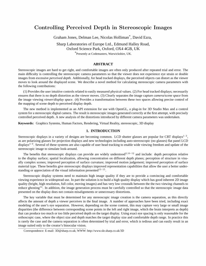
Figure 1. Results of the human factors study of subjects lookingat a simple scene, viewing distance 700mm from a 13.8” display.The range of depths tolerated before loss of stereo fusion can bequite large.
Condition: Mallet Box (look down)
1
2
3
4
7
8
1
2
3
4
5
7
8
5
66
-2 -1.5 -1 -0.5 0 0.5 1
Su
bje
ct
Distance in virtual space (m)
in
out
in -0.15 -0.099 -0.069 -0.097 -0.18 -0.926 -0.117 -0.062
out 0.112 0.19 0.113 0.11 0.106 0.103 0.093 0.117
1 2 3 4 5 6 7 8
Distance (m)
subject
Figure 2. Results of the human factors study of subjects lookingat a Mallet unit. The depths tolerated before stereo fusion is lostare much smaller than before.
1.1. Human factors analysis of stereoscopic displays
The issue of viewer comfort for stereoscopic displays is studied in detail in relatively few human factors publications16–19.However, a similar conclusion is drawn by all the studies: the amount of disparity in stereoscopic images should be limitedto be within a defined comfortable range. The main reason given for this is that the human visual system normally operatessuch that the convergence of the eyes and the accommodation (focus) are linked. For all stereoscopic displays this relationshipis thought to be stressed by requiring the viewer’s eyes to converge perceived depth a long way off the display plane but stillbeing required to focus on the display plane. Limiting disparity ensures that the viewer’s perceived depth is controlled and theconvergence/accommodation link is not stressed.
The suggested limits on the amount of disparity in a stereoscopic image14,19, in the region of 24min arc, do not allow a largeamount of depth to be reproduced. For typical desktop displays with a viewing distance in the region of 700mm this puts thecomfortable perceived depth range as little as 50mm in front and 60mm behind the display surface. One immediate implicationis that most objects and scenes will have depth compression when they are shown on a stereoscopic display.
Recently some human factors research was carried out using a 13.8” LCD autostereoscopic display from Sharp Laboratoriesof Europe20. The fusional thresholds of several subjects were measured, both into and out of the screen, for different types ofstimuli and different task requirements. (Viewing distance for all tests was 700mm).
The results showed several points of interest:
• When the subject is free to alter the depth in a simple scene at will, the limit behind the display at which fusion was lostcould be up to 20m, and was typically greater than 2m. The depth limit in front of the display was generally between300mm and 500mm with the maximum reported being 540mm.
• With the same simple scene, but when the subject had to look away from the display before carrying out the next step indepth the limits were much closer. Some of the subjects could still achieve distances greater than 2m behind the display,but several found the limit between 500mm and 1m. The limits to the front were between 200mm to 400mm with onesubject still able to reach 520mm (See figure 1).
• When the subjects were looking at a much more sensitive test, a modified Mallet unit, and free to move it to the limits,the maximum depth behind the screen was between 80mm and 150mm. The range in front of the screen was typicallybetween 100mm and 300mm, with one subject reaching 500mm.
• When the subject has to look away from Mallet unit all but one reached a maximum depth between 60mm and 150mmbehind the display and 110mm in front of the display (See figure 2).
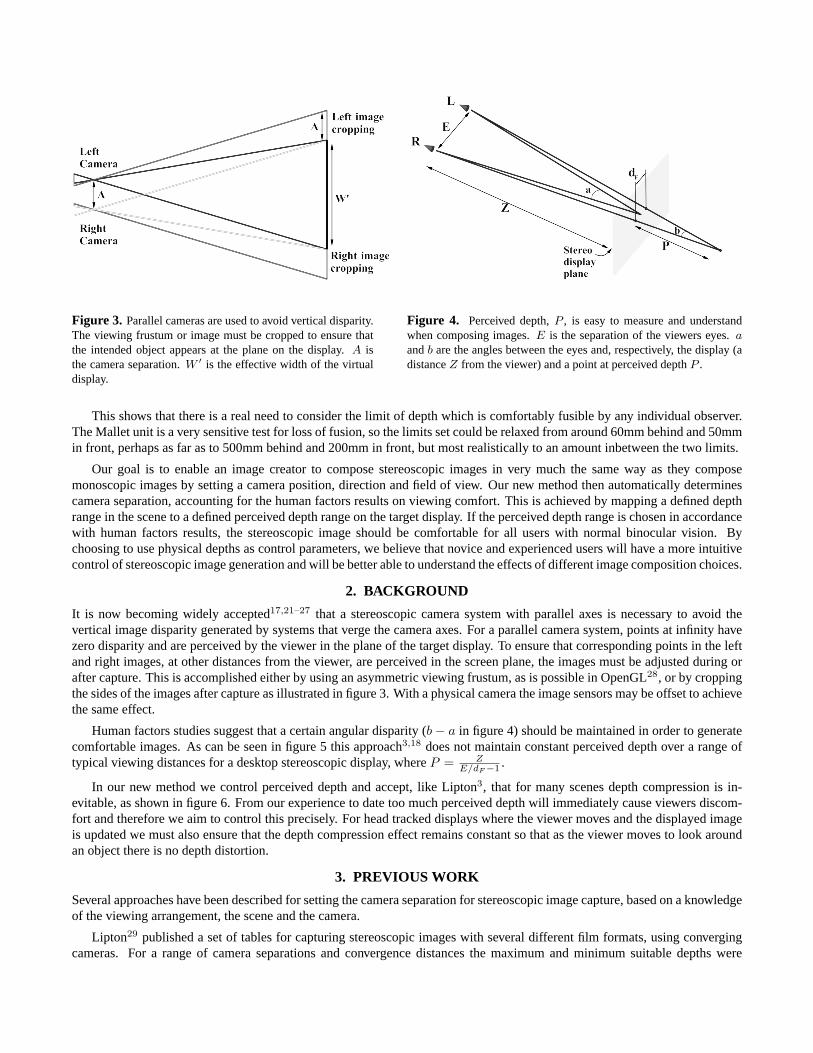
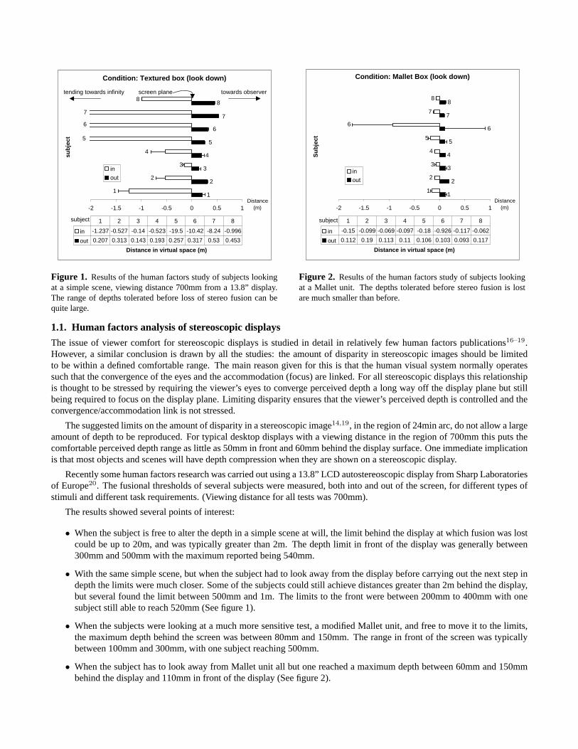
Figure 3. Parallel cameras are used to avoid vertical disparity.The viewing frustum or image must be cropped to ensure thatthe intended object appears at the plane on the display. A isthe camera separation. W ′ is the effective width of the virtualdisplay.
Figure 4. Perceived depth, P , is easy to measure and understandwhen composing images. E is the separation of the viewers eyes. aand b are the angles between the eyes and, respectively, the display (adistance Z from the viewer) and a point at perceived depth P .
This shows that there is a real need to consider the limit of depth which is comfortably fusible by any individual observer.The Mallet unit is a very sensitive test for loss of fusion, so the limits set could be relaxed from around 60mm behind and 50mmin front, perhaps as far as to 500mm behind and 200mm in front, but most realistically to an amount inbetween the two limits.
Our goal is to enable an image creator to compose stereoscopic images in very much the same way as they composemonoscopic images by setting a camera position, direction and field of view. Our new method then automatically determinescamera separation, accounting for the human factors results on viewing comfort. This is achieved by mapping a defined depthrange in the scene to a defined perceived depth range on the target display. If the perceived depth range is chosen in accordancewith human factors results, the stereoscopic image should be comfortable for all users with normal binocular vision. Bychoosing to use physical depths as control parameters, we believe that novice and experienced users will have a more intuitivecontrol of stereoscopic image generation and will be better able to understand the effects of different image composition choices.
2. BACKGROUND
It is now becoming widely accepted17,21–27 that a stereoscopic camera system with parallel axes is necessary to avoid thevertical image disparity generated by systems that verge the camera axes. For a parallel camera system, points at infinity havezero disparity and are perceived by the viewer in the plane of the target display. To ensure that corresponding points in the leftand right images, at other distances from the viewer, are perceived in the screen plane, the images must be adjusted during orafter capture. This is accomplished either by using an asymmetric viewing frustum, as is possible in OpenGL28, or by croppingthe sides of the images after capture as illustrated in figure 3. With a physical camera the image sensors may be offset to achievethe same effect.
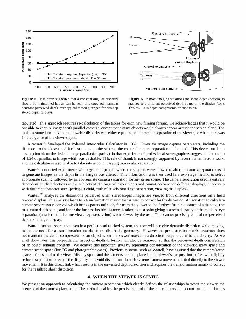
Human factors studies suggest that a certain angular disparity (b − a in figure 4) should be maintained in order to generatecomfortable images. As can be seen in figure 5 this approach3,18 does not maintain constant perceived depth over a range oftypical viewing distances for a desktop stereoscopic display, where P = Z
E/dF −1 .
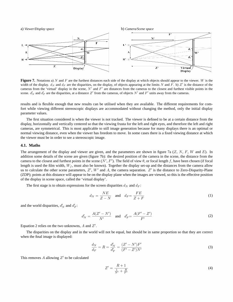
In our new method we control perceived depth and accept, like Lipton3, that for many scenes depth compression is in-evitable, as shown in figure 6. From our experience to date too much perceived depth will immediately cause viewers discom-fort and therefore we aim to control this precisely. For head tracked displays where the viewer moves and the displayed imageis updated we must also ensure that the depth compression effect remains constant so that as the viewer moves to look aroundan object there is no depth distortion.
3. PREVIOUS WORK
Several approaches have been described for setting the camera separation for stereoscopic image capture, based on a knowledgeof the viewing arrangement, the scene and the camera.
Lipton29 published a set of tables for capturing stereoscopic images with several different film formats, using convergingcameras. For a range of camera separations and convergence distances the maximum and minimum suitable depths were
0
20
40
60
80
100
120
140
160
500 550 600 650 700 750 800 850 900Z, viewing distance (mm)
P, p
erce
ived
dep
th (
mm
)
Constant angular disparity, (b-a) = 35’Constant perceived depth, P = 60mm
Figure 5. It is often suggested that a constant angular disparityshould be maintained but as can be seen this does not maintainconstant perceived depth over typical viewing ranges for desktopstereoscopic displays.
Figure 6. In most imaging situations the scene depth (bottom) ismapped to a different perceived depth range on the display (top).This results in depth compression or expansion.
tabulated. This approach requires re-calculation of the tables for each new filming format. He acknowledges that it would bepossible to capture images with parallel cameras, except that distant objects would always appear around the screen plane. Thetables assumed the maximum allowable disparity was either equal to the interocular separation of the viewer, or when there was1◦ divergence of the viewers eyes.
Kitrosser24 developed the Polaroid Interocular Calculator in 1952. Given the image capture parameters, including thedistances to the closest and furthest points on the subject, the required camera separation is obtained. This device made anassumption about the desired image parallax(disparity), in that experience of professional stereographers suggested that a ratioof 1:24 of parallax to image width was desirable. This rule of thumb is not strongly supported by recent human factors work,and the calculator is also unable to take into account varying interocular separation.
Ware30 conducted experiments with a group of people, where the subjects were allowed to alter the camera separation usedto generate images as the depth in the images was altered. This information was then used in a two stage method to selectappropriate scaling followed by an appropriate camera separation for any given scene. The camera separation used is entirelydependent on the selections of the subjects of the original experiments and cannot account for different displays, or viewerswith different characteristics (perhaps a child, with relatively small eye separation, viewing the display).
Wartell27 analyses the distortions perceived when stereoscopic images are viewed from different directions on a headtracked display. This analysis leads to a transformation matrix that is used to correct for the distortion. An equation to calculatecamera separation is derived which brings points infinitely far from the viewer to the furthest fusible distance of a display. Themaximum depth plane, and hence the furthest fusible distance, is taken to be a point giving a screen disparity of the modeled eyeseparation (smaller than the true viewer eye separation) when viewed by the user. This cannot precisely control the perceiveddepth on a target display.
Wartell further asserts that even in a perfect head tracked system, the user will perceive dynamic distortion while moving,hence the need for a transformation matrix to pre-distort the geometry. However the pre-distortion matrix presented doesnot maintain the depth compression of an object when the viewer moves in a direction perpendicular to the display. As weshall show later, this perpendicular aspect of depth distortion can also be removed, so that the perceived depth compressionof an object remains constant. We achieve this important goal by separating consideration of the viewer/display space andcamera/scene space (for CG and photographic cases). Previous systems, such as Wartell, have assumed that the camera/scenespace is first scaled to the viewer/display space and the cameras are then placed at the viewer’s eye positions, often with slightlyreduced separation to reduce the disparity and avoid discomfort. In such systems camera movement is tied directly to the viewermovement. It is this direct link which results in the unwanted depth distortion and requires the transformation matrix to correctfor the resulting shear distortion.
4. WHEN THE VIEWER IS STATIC
We present an approach to calculating the camera separation which clearly defines the relationships between the viewer, thescene, and the camera placement. The method enables the precise control of these parameters to account for human factors
a) Viewer/Display space b) Camera/Scene space
Figure 7. Notations a) N and F are the furthest distances each side of the display at which objects should appear to the viewer. W is thewidth of the display. dN and dF are the disparities, on the display, of objects appearing at the limits N and F . b) Z′ is the distance of thecameras from the ‘virtual’ display in the scene, N ′ and F ′ are distances from the cameras to the closest and furthest visible points in thescene. d′
N and d′F are the disparities, at a distance Z′ from the cameras, of objects N ′ and F ′ units away from the cameras.
results and is flexible enough that new results can be utilised when they are available. The different requirements for com-fort while viewing different stereoscopic displays are accommodated without changing the method, only the initial displayparameter values.
The first situation considered is when the viewer is not tracked. The viewer is defined to be at a certain distance from thedisplay, horizontally and vertically centered so that the viewing frusta for the left and right eyes, and therefore the left and rightcameras, are symmetrical. This is most applicable to still image generation because for many displays there is an optimal ornormal viewing distance, even when the viewer has freedom to move. In some cases there is a fixed viewing distance at whichthe viewer must be in order to see a stereoscopic image.
4.1. Maths
The arrangement of the display and viewer are given, and the parameters are shown in figure 7a (Z, N , F , W and E). Inaddition some details of the scene are given (figure 7b): the desired position of the camera in the scene, the distance from thecamera to the closest and furthest points in the scene (N ′, F ′). The field of view θ, or focal length f , have been chosen (if focallength is used the film width, Wf , must also be known). Together the display set-up and the distances from the camera allowus to calculate the other scene parameters, Z ′, W ′ and A, the camera separation. Z ′ is the distance to Zero-Disparity-Plane(ZDP); points at this distance will appear to be on the display plane when the images are viewed, so this is the effective positionof the display in scene space, called the ‘virtual display’.
The first stage is to obtain expressions for the screen disparities dN and dF :
dN =NE
Z − Nand dF =
FE
Z + F(1)
and the world disparities, d′N and d′F :
d′N =A(Z ′ − N ′)
N ′ and d′F =A(F ′ − Z ′)
F ′ (2)
Equation 2 relies on the two unknowns, A and Z ′.
The disparities on the display and in the world will not be equal, but should be in same proportion so that they are correctwhen the final image is displayed:
dN
dF= R =
d′Nd′F
=(Z ′ − N ′)F ′
(F ′ − Z ′)N ′ (3)
This removes A allowing Z ′ to be calculated
Z ′ =R + 11
N ′ + RF ′
(4)
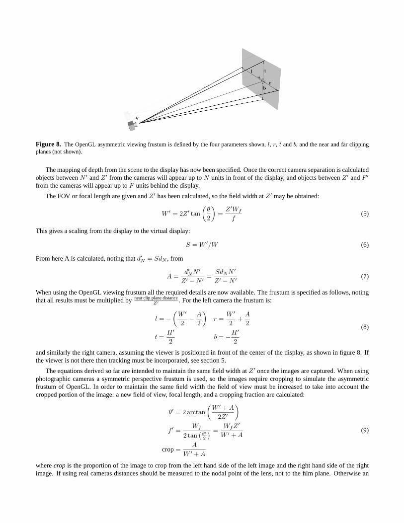
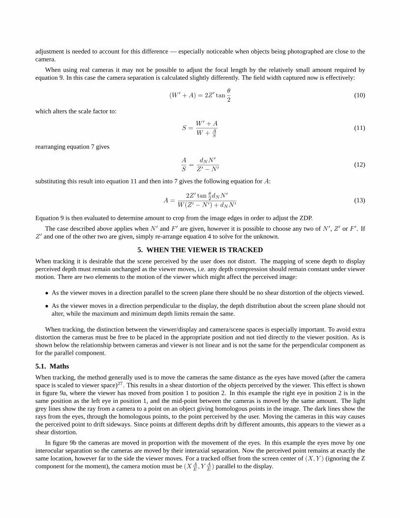
Figure 8. The OpenGL asymmetric viewing frustum is defined by the four parameters shown, l, r, t and b, and the near and far clippingplanes (not shown).
The mapping of depth from the scene to the display has now been specified. Once the correct camera separation is calculatedobjects between N ′ and Z ′ from the cameras will appear up to N units in front of the display, and objects between Z ′ and F ′
from the cameras will appear up to F units behind the display.
The FOV or focal length are given and Z ′ has been calculated, so the field width at Z ′ may be obtained:
W ′ = 2Z ′ tan(
θ
2
)=
Z ′Wf
f(5)
This gives a scaling from the display to the virtual display:
S = W ′/W (6)
From here A is calculated, noting that d′N = SdN , from
A =d′NN ′
Z ′ − N ′ =SdNN ′
Z ′ − N ′ (7)
When using the OpenGL viewing frustum all the required details are now available. The frustum is specified as follows, notingthat all results must be multiplied by near clip plane distance
Z′ . For the left camera the frustum is:
l = −(
W ′
2− A
2
)r =
W ′
2+
A
2
t =H ′
2b = −H ′
2
(8)
and similarly the right camera, assuming the viewer is positioned in front of the center of the display, as shown in figure 8. Ifthe viewer is not there then tracking must be incorporated, see section 5.
The equations derived so far are intended to maintain the same field width at Z ′ once the images are captured. When usingphotographic cameras a symmetric perspective frustum is used, so the images require cropping to simulate the asymmetricfrustum of OpenGL. In order to maintain the same field width the field of view must be increased to take into account thecropped portion of the image: a new field of view, focal length, and a cropping fraction are calculated:
θ′ = 2 arctan(
W ′ + A
2Z ′
)
f ′ =Wf
2 tan(
θ′2
) =WfZ ′
W ′ + A
crop =A
W ′ + A
(9)
where crop is the proportion of the image to crop from the left hand side of the left image and the right hand side of the rightimage. If using real cameras distances should be measured to the nodal point of the lens, not to the film plane. Otherwise an
adjustment is needed to account for this difference — especially noticeable when objects being photographed are close to thecamera.
When using real cameras it may not be possible to adjust the focal length by the relatively small amount required byequation 9. In this case the camera separation is calculated slightly differently. The field width captured now is effectively:
(W ′ + A) = 2Z ′ tanθ
2(10)
which alters the scale factor to:
S =W ′ + A
W + AS
(11)
rearranging equation 7 gives
A
S=
dNN ′
Z ′ − N ′ (12)
substituting this result into equation 11 and then into 7 gives the following equation for A:
A =2Z ′ tan θ
2dNN ′
W (Z ′ − N ′) + dNN ′ (13)
Equation 9 is then evaluated to determine amount to crop from the image edges in order to adjust the ZDP.
The case described above applies when N ′ and F ′ are given, however it is possible to choose any two of N ′, Z ′ or F ′. IfZ ′ and one of the other two are given, simply re-arrange equation 4 to solve for the unknown.
5. WHEN THE VIEWER IS TRACKED
When tracking it is desirable that the scene perceived by the user does not distort. The mapping of scene depth to displayperceived depth must remain unchanged as the viewer moves, i.e. any depth compression should remain constant under viewermotion. There are two elements to the motion of the viewer which might affect the perceived image:
• As the viewer moves in a direction parallel to the screen plane there should be no shear distortion of the objects viewed.
• As the viewer moves in a direction perpendicular to the display, the depth distribution about the screen plane should notalter, while the maximum and minimum depth limits remain the same.
When tracking, the distinction between the viewer/display and camera/scene spaces is especially important. To avoid extradistortion the cameras must be free to be placed in the appropriate position and not tied directly to the viewer position. As isshown below the relationship between cameras and viewer is not linear and is not the same for the perpendicular component asfor the parallel component.
5.1. Maths
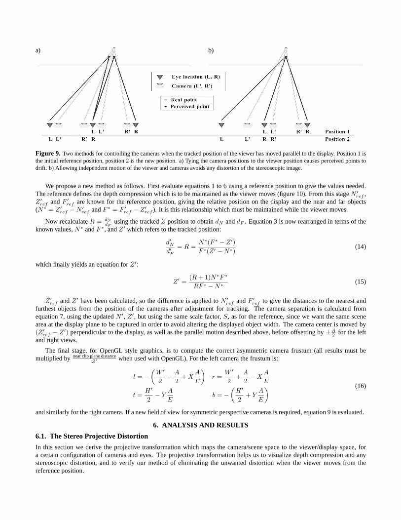
When tracking, the method generally used is to move the cameras the same distance as the eyes have moved (after the cameraspace is scaled to viewer space)27. This results in a shear distortion of the objects perceived by the viewer. This effect is shownin figure 9a, where the viewer has moved from position 1 to position 2. In this example the right eye in position 2 is in thesame position as the left eye in position 1, and the mid-point between the cameras is moved by the same amount. The lightgrey lines show the ray from a camera to a point on an object giving homologous points in the image. The dark lines show therays from the eyes, through the homologous points, to the point perceived by the user. Moving the cameras in this way causesthe perceived point to drift sideways. Since points at different depths drift by different amounts, this appears to the viewer as ashear distortion.
In figure 9b the cameras are moved in proportion with the movement of the eyes. In this example the eyes move by oneinterocular separation so the cameras are moved by their interaxial separation. Now the perceived point remains at exactly thesame location, however far to the side the viewer moves. For a tracked offset from the screen center of (X, Y ) (ignoring the Zcomponent for the moment), the camera motion must be (X A
E , Y AE ) parallel to the display.
a) b)
Figure 9. Two methods for controlling the cameras when the tracked position of the viewer has moved parallel to the display. Position 1 isthe initial reference position, position 2 is the new position. a) Tying the camera positions to the viewer position causes perceived points todrift. b) Allowing independent motion of the viewer and cameras avoids any distortion of the stereoscopic image.
We propose a new method as follows. First evaluate equations 1 to 6 using a reference position to give the values needed.The reference defines the depth compression which is to be maintained as the viewer moves (figure 10). From this stage N ′
ref ,Z ′
ref and F ′ref are known for the reference position, giving the relative position on the display and the near and far objects
(N∗ = Z ′ref − N ′
ref and F ∗ = F ′ref − Z ′
ref ). It is this relationship which must be maintained while the viewer moves.
Now recalculate R = dN
dFusing the tracked Z position to obtain dN and dF . Equation 3 is now rearranged in terms of the
known values, N∗ and F ∗, and Z ′ which refers to the tracked position:
d′Nd′F
= R =N∗(F ∗ − Z ′)F ∗(Z ′ − N∗)
(14)
which finally yields an equation for Z ′:
Z ′ =(R + 1)N∗F ∗
RF ∗ − N∗ (15)
Z ′ref and Z ′ have been calculated, so the difference is applied to N ′
ref and F ′ref to give the distances to the nearest and
furthest objects from the position of the cameras after adjustment for tracking. The camera separation is calculated fromequation 7, using the updated N ′, Z ′, but using the same scale factor, S, as for the reference, since we want the same scenearea at the display plane to be captured in order to avoid altering the displayed object width. The camera center is moved by(Z ′
ref − Z ′) perpendicular to the display, as well as the parallel motion described above, before offsetting by ±A2 for the left
and right views.
The final stage, for OpenGL style graphics, is to compute the correct asymmetric camera frustum (all results must bemultiplied by near clip plane distance
Z′ when used with OpenGL). For the left camera the frustum is:
l = −(
W ′
2− A
2+ X
A
E
)r =
W ′
2+
A
2− X
A
E
t =H ′
2− Y
A
Eb = −
(H ′
2+ Y
A
E
) (16)
and similarly for the right camera. If a new field of view for symmetric perspective cameras is required, equation 9 is evaluated.
6. ANALYSIS AND RESULTS
6.1. The Stereo Projective Distortion
In this section we derive the projective transformation which maps the camera/scene space to the viewer/display space, fora certain configuration of cameras and eyes. The projective transformation helps us to visualize depth compression and anystereoscopic distortion, and to verify our method of eliminating the unwanted distortion when the viewer moves from thereference position.
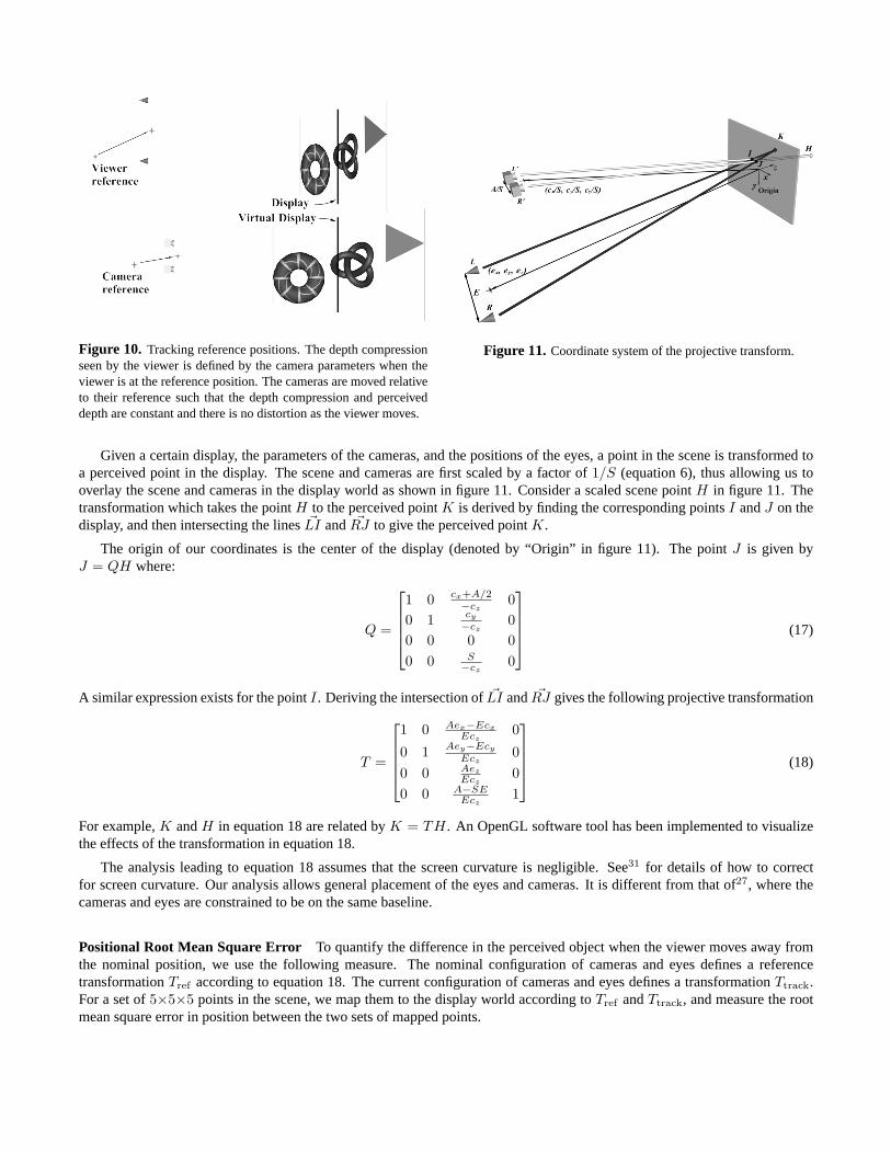
Figure 10. Tracking reference positions. The depth compressionseen by the viewer is defined by the camera parameters when theviewer is at the reference position. The cameras are moved relativeto their reference such that the depth compression and perceiveddepth are constant and there is no distortion as the viewer moves.
Figure 11. Coordinate system of the projective transform.
Given a certain display, the parameters of the cameras, and the positions of the eyes, a point in the scene is transformed toa perceived point in the display. The scene and cameras are first scaled by a factor of 1/S (equation 6), thus allowing us tooverlay the scene and cameras in the display world as shown in figure 11. Consider a scaled scene point H in figure 11. Thetransformation which takes the point H to the perceived point K is derived by finding the corresponding points I and J on thedisplay, and then intersecting the lines �LI and �RJ to give the perceived point K.
The origin of our coordinates is the center of the display (denoted by “Origin” in figure 11). The point J is given byJ = QH where:
Q =
1 0 cx+A/2−cz
00 1 cy
−cz0
0 0 0 00 0 S
−cz0
(17)
A similar expression exists for the point I . Deriving the intersection of �LI and �RJ gives the following projective transformation
T =
1 0 Aex−Ecx
Ecz0
0 1 Aey−Ecy
Ecz0
0 0 Aez
Ecz0
0 0 A−SEEcz
1
(18)
For example, K and H in equation 18 are related by K = TH . An OpenGL software tool has been implemented to visualizethe effects of the transformation in equation 18.
The analysis leading to equation 18 assumes that the screen curvature is negligible. See31 for details of how to correctfor screen curvature. Our analysis allows general placement of the eyes and cameras. It is different from that of27, where thecameras and eyes are constrained to be on the same baseline.
Positional Root Mean Square Error To quantify the difference in the perceived object when the viewer moves away fromthe nominal position, we use the following measure. The nominal configuration of cameras and eyes defines a referencetransformation Tref according to equation 18. The current configuration of cameras and eyes defines a transformation Ttrack.For a set of 5×5×5 points in the scene, we map them to the display world according to Tref and Ttrack, and measure the rootmean square error in position between the two sets of mapped points.
6.2. Results
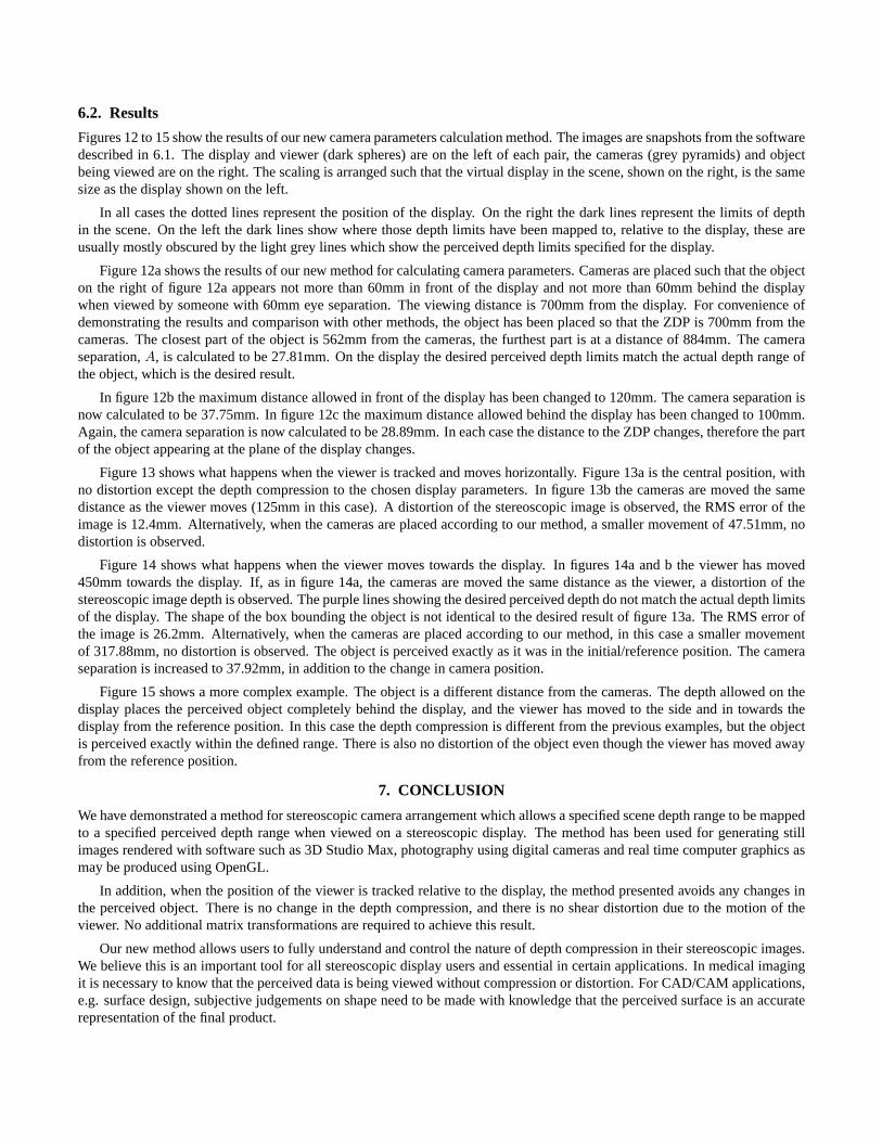
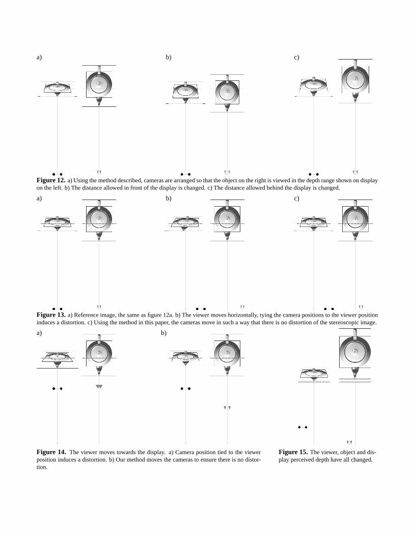
Figures 12 to 15 show the results of our new camera parameters calculation method. The images are snapshots from the softwaredescribed in 6.1. The display and viewer (dark spheres) are on the left of each pair, the cameras (grey pyramids) and objectbeing viewed are on the right. The scaling is arranged such that the virtual display in the scene, shown on the right, is the samesize as the display shown on the left.
In all cases the dotted lines represent the position of the display. On the right the dark lines represent the limits of depthin the scene. On the left the dark lines show where those depth limits have been mapped to, relative to the display, these areusually mostly obscured by the light grey lines which show the perceived depth limits specified for the display.
Figure 12a shows the results of our new method for calculating camera parameters. Cameras are placed such that the objecton the right of figure 12a appears not more than 60mm in front of the display and not more than 60mm behind the displaywhen viewed by someone with 60mm eye separation. The viewing distance is 700mm from the display. For convenience ofdemonstrating the results and comparison with other methods, the object has been placed so that the ZDP is 700mm from thecameras. The closest part of the object is 562mm from the cameras, the furthest part is at a distance of 884mm. The cameraseparation, A, is calculated to be 27.81mm. On the display the desired perceived depth limits match the actual depth range ofthe object, which is the desired result.
In figure 12b the maximum distance allowed in front of the display has been changed to 120mm. The camera separation isnow calculated to be 37.75mm. In figure 12c the maximum distance allowed behind the display has been changed to 100mm.Again, the camera separation is now calculated to be 28.89mm. In each case the distance to the ZDP changes, therefore the partof the object appearing at the plane of the display changes.
Figure 13 shows what happens when the viewer is tracked and moves horizontally. Figure 13a is the central position, withno distortion except the depth compression to the chosen display parameters. In figure 13b the cameras are moved the samedistance as the viewer moves (125mm in this case). A distortion of the stereoscopic image is observed, the RMS error of theimage is 12.4mm. Alternatively, when the cameras are placed according to our method, a smaller movement of 47.51mm, nodistortion is observed.
Figure 14 shows what happens when the viewer moves towards the display. In figures 14a and b the viewer has moved450mm towards the display. If, as in figure 14a, the cameras are moved the same distance as the viewer, a distortion of thestereoscopic image depth is observed. The purple lines showing the desired perceived depth do not match the actual depth limitsof the display. The shape of the box bounding the object is not identical to the desired result of figure 13a. The RMS error ofthe image is 26.2mm. Alternatively, when the cameras are placed according to our method, in this case a smaller movementof 317.88mm, no distortion is observed. The object is perceived exactly as it was in the initial/reference position. The cameraseparation is increased to 37.92mm, in addition to the change in camera position.
Figure 15 shows a more complex example. The object is a different distance from the cameras. The depth allowed on thedisplay places the perceived object completely behind the display, and the viewer has moved to the side and in towards thedisplay from the reference position. In this case the depth compression is different from the previous examples, but the objectis perceived exactly within the defined range. There is also no distortion of the object even though the viewer has moved awayfrom the reference position.
7. CONCLUSION
We have demonstrated a method for stereoscopic camera arrangement which allows a specified scene depth range to be mappedto a specified perceived depth range when viewed on a stereoscopic display. The method has been used for generating stillimages rendered with software such as 3D Studio Max, photography using digital cameras and real time computer graphics asmay be produced using OpenGL.
In addition, when the position of the viewer is tracked relative to the display, the method presented avoids any changes inthe perceived object. There is no change in the depth compression, and there is no shear distortion due to the motion of theviewer. No additional matrix transformations are required to achieve this result.
Our new method allows users to fully understand and control the nature of depth compression in their stereoscopic images.We believe this is an important tool for all stereoscopic display users and essential in certain applications. In medical imagingit is necessary to know that the perceived data is being viewed without compression or distortion. For CAD/CAM applications,e.g. surface design, subjective judgements on shape need to be made with knowledge that the perceived surface is an accuraterepresentation of the final product.
8. FUTUREWe believe that future work in this area is important in order to enable more widespread use of stereoscopic displays. Inparticular further human factors work on understanding and defining comfortable perceived depth ranges is required.
There are several implications of this work, including the need to capture images for a specific display configuration. Forstill images this implies a need to adjust the camera separation after capture depending on the display characteristics. Thiswill require high fidelity image based rendering to generate the images as seen from the correct camera positions. This is anexcellent challenge for future work in image based rendering, particularly as binocular vision can easily identify errors in depthinterpolation.
ACKNOWLEDGMENTSThe authors gratefully acknowledge their colleagues at Sharp Labs of Europe for many discussions concerning this work,and supporting the display hardware; John Wann and Anna Plooy at the Action Research Laboratory, in the Department ofPsychology at Reading University and finally we thank Sharp Corporate R&D Group for their continuing support of our work.
REFERENCES1. ELSA AG, 3D Revelator, Quick Start Guide, Aachen, Germany, 1999.2. M. Agrawala, A. C. Beers, B. Frohlich, P. Hanrahan, I. McDowall, and M. Bolas, “The Two-User Responsive Workbench:: Support for
Collaboration Through Independent Views of a Shared Space,” in Computer Graphics Proceedings, Annual Conference Series, 1997(ACM SIGGRAPH 97 Proceedings), pp. 327 – 332, 1997.
3. L. Lipton, Stereographics, Developers Handbook, Stereographics Corporation, 1997.4. J. Eichenlaub, “A Lightweight, Compact 2D/3D Autostereoscopic LCD Backlight for Games, Monitor and Notebook Applications,” in
Proceedings of the SPIE, vol. 3295, pp. 180 – 185, Jan. 1998.5. H. Morishima, H. Nose, N. Taniguchi, K. Inogucchi, and S. Matsumura, “Rear Cross Lenticular 3D Display Without Eyeglasses,” in
Proceedings of the SPIE, vol. 3295, pp. 193 – 222, Jan. 1998.6. Sanyo, SANYO Announces Development of Non-glasses 15-inch XGA 3D Display, Sanyo Electric Corporation Limited,
http://www.sanyo.com/koho/hypertext4-eng/9707news-e/07243dd.htm, 1997.7. A. Schwerdtner and H. Heidrich, “Dresden 3D display (D4D),” in Proceedings of the SPIE, vol. 3295, pp. 203 – 210, Jan. 1998.8. D. Trayner and E. Orr, “Autostereoscopic Display using Holographic Optical Elements,” in Proceedings of the SPIE, vol. 2653, pp. 65
– 74, Jan. 1996.9. G. J. Woodgate, D. Ezra, J. Harrold, N. S. Holliman, G. R. Jones, and R. R. Moseley, “Autostereoscopic 3D Display Systems with
Observer Tracking,” Signal Processing: Image Communication 14, pp. 131 – 145, 1998.10. D. B. Diner and D. H. Fender, eds., Human engineering in stereoscopic viewing devices, Plenum Press, ISBN 0-306-44667-7, 1993.11. I. P. Howard and B. J. Rogers, Binocular Vision and Stereopsis, Oxford University Press, ISBN 0-19-508476-4, 1995.12. D. McAllister, ed., Stereo computer graphics and other true 3D technologies, Princeton University Press, ISBN 0-691-08741-5, 1993.13. T. Mitsuhashi, “Subjective Image Position in Stereoscopic TV Systems - Considerations on Comfortable Stereoscopic Images,” in
Proceedings of the SPIE, vol. 2179, pp. 259 – 266, Mar. 1994.14. R. Sand and A. Chiari, eds., Stereoscopic Television: Standards, Technology and Signal Processing, European Commission, Directorate
General XIII-B, Brussels, 1998.15. C. Ware and G. Franck, “Evaluating Stereo and Motion Cues for Visualizing Information Nets in Three Dimensions,” tech. rep., Uni-
versity of New Brunswick, Technical Document #TR94-082, 1994.16. N. Hiruma and T. Fukuda, “Accomodation Response to Binocular Stereoscopic TV Images and their Viewing Conditions,” SMPTE
Journal , pp. 1137 – 1144, Dec. 1993.17. A. Woods, T. Docherty, and R. Koch, “Image Distortions in Stereoscopic Video Systems,” in Proceedings of the SPIE, vol. 1915, pp. 36
– 48, 1993.18. M. Wopking, “Viewing Comfort with Stereoscopic Pictures: An Experimental Study on the Subjective Effects of Disparity Magnitude
and Depth of Focus,” Journal of the SID 3(3), pp. 101 – 103, 1995.19. Y.-Y. Yeh and L. D. Silverstien, “Limits of Fusion and Depth Judgement in Stereoscopic Color Displays,” Human Factors 32(1), pp. 45
– 60, 1990.20. Action Research Laboratory, Sharp 3D Screen, Evaluation Report: Stages 1-3, Private communication to Sharp Labs., 2000.21. J. Baker, “Generating Images for a Time-Multiplexed, Stereoscopic Computer Graphics System,” in True 3D Imaging Techniques and
Display Technologies, Proc. SPIE, vol. 761, pp. 44–52, 1987.22. V. Grinberg, G. Podnar, and M. Seigel, “Geometry of Binocular Imaging,” in Proceedings of the SPIE, vol. 2177, pp. 56 – 65, Feb.
1994.23. L. F. Hodges and E. T. Davis, “Geometric Considerations for Stereoscopic Virtual Environments,” Presence 2, pp. 34 – 43, Winter 1993.24. S. Kitrosser, “Photography in the Service of Stereoscopy,” Journal of Imaging Science and Technology 42, pp. 295 – 300, July/August
1998.25. W. Robinett and R. Holloway, “The Visual Display Transformation for Virtual Reality,” Presence 4, pp. 1 – 23, Winter 1995.26. D. A. Southard, “Viewing Model for Virtual Environment Displays,” Journal of Electronic Imaging 4, pp. 413 – 420, Oct. 1995.27. Z. Wartell, L. F. Hodges, and W. Ribarsky, “Balancing Fusion, Image Depth and Distortion in Stereoscopic Head-Tracked Displays,” in
Computer Graphics Proceedings, Annual Conference Series, 1999 (ACM SIGGRAPH 99 Proceedings), pp. 351 – 358, 1999.28. R. Akka, “Converting Existing Applications to Support High Quality Stereoscopy,” in Proceedings of the SPIE, vol. 3639, pp. 290 –
299, Jan. 1999.29. L. Lipton, Foundations of the Stereoscopic Cinema: A Study in Depth, Van Nostrand Reinhold Company, 1982.30. C. Ware, C. Gobrecht, and M. Paton, “Algorithm for Dynamic Disparity Adjustment,” in Proceedings of the SPIE – The International
Society for Optical Engineering, Stereoscopic Displays and Virtual Reality Systems II, vol. 2409, pp. 150 – 156, Feb. 1995.31. M. Deering, “High Resolution Virtual Reality,” in Computer Graphics Proceedings, Annual Conference Series, 1992 (ACM SIGGRAPH
92 Proceedings), vol. 26, pp. 195 – 201, 1992.
a) b) c)
Figure 12. a) Using the method described, cameras are arranged so that the object on the right is viewed in the depth range shown on displayon the left. b) The distance allowed in front of the display is changed. c) The distance allowed behind the display is changed.
a) b) c)
Figure 13. a) Reference image, the same as figure 12a. b) The viewer moves horizontally, tying the camera positions to the viewer positioninduces a distortion. c) Using the method in this paper, the cameras move in such a way that there is no distortion of the stereoscopic image.
a) b)
Figure 14. The viewer moves towards the display. a) Camera position tied to the viewerposition induces a distortion. b) Our method moves the cameras to ensure there is no distor-tion.
Figure 15. The viewer, object and dis-play perceived depth have all changed.