Embed Size (px)
Citation preview

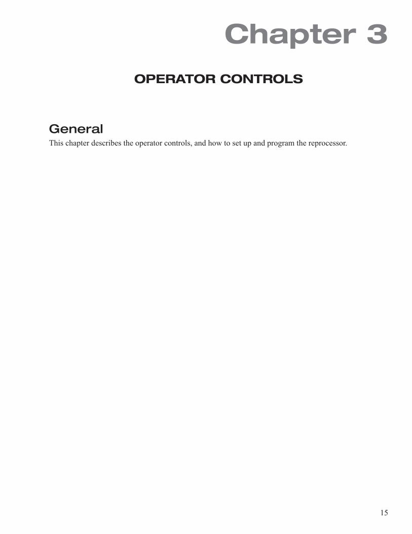
1
Service Manual
DSD-201Endoscope Reprocessing System
2
MEDIVATORS® and ACTRIL® are registered trademarks of Medivators Inc. PENTAX® is a registered trademark of Hoya Corporation. OLYMPUS® is a registered trademark of Olympus Corporation. FUJIFILMTM is a trademark of Fujifilm Corporation.
MM03-0047 REV H
© 2015 Medivators Inc.
All Rights Reserved.
All rights reserved. This publication is protected by copyright. Copying, disclosure to others, or the use of this publication is prohibited without the express written consent of Medivators Inc.
MEDIVATORS reserves the right to make changes in the specifications shown herein without notice or obligation. Contact your MEDIVATORS representative or MEDIVATORS customer service for more information
3
TABLE OF CONTENTS
CHAPTER 1 - INTRODUCTIONUsing This Manual ........................................................................................................................................................ 5Safety .......................................................................................................................................................................... 6
Intended Use ........................................................................................................................................................ 6Operator Safety ..................................................................................................................................................... 6
Guidelines .................................................................................................................................................................... 7Installation And Maintenance ................................................................................................................................ 7Water Quality ........................................................................................................................................................ 7Detergent Solution ................................................................................................................................................ 8Disinfectant Solution ............................................................................................................................................. 8Monitoring Disinfectant Potency ............................................................................................................................ 8Endoscope Precleaning And Testing ...................................................................................................................... 9
Cleaning And Disinfection ............................................................................................................................................. 9 Professional Guidelines ............................................................................................................................................. 10
CHAPTER 2 - INSTALLATION General ...................................................................................................................................................................... 11System Supply .......................................................................................................................................................... 12
Water Supply ..................................................................................................................................................... 12Electrical Supply ................................................................................................................................................ 12Air Supply .......................................................................................................................................................... 12System Drain ..................................................................................................................................................... 13Installation Verification ....................................................................................................................................... 13
CHAPTER 3 - OPERATION CONTROLS General ...................................................................................................................................................................... 15Control Panel ............................................................................................................................................................. 16LED Indicators ........................................................................................................................................................... 17LCD Screen ............................................................................................................................................................... 18Numeric Keypad ........................................................................................................................................................ 19Function Keys ............................................................................................................................................................ 20Setting Up The Reprocessor ....................................................................................................................................... 22
Load Disinfectant From Basin ............................................................................................................................. 22Load Disinfectant With Internal Pump ................................................................................................................. 24Automatic Disinfectant Dump ............................................................................................................................. 25Dump Disinfectant With Internal Pump ................................................................................................................ 27Set The Date ...................................................................................................................................................... 29Set The Time ...................................................................................................................................................... 31Display Software Version .................................................................................................................................... 33Water Line Sanitize ............................................................................................................................................. 34Display Log ........................................................................................................................................................ 36Clear Log ............................................................................................................................................................ 37Clear Disinfectant Cycle Count ............................................................................................................................ 38
Programming The Reprocessor .................................................................................................................................. 39Input Program .................................................................................................................................................... 39Disinfectant Warning Inhibit ................................................................................................................................ 45Display Temperatures ......................................................................................................................................... 46Set Heater-on Time ............................................................................................................................................ 47Set Heater-off Time ............................................................................................................................................ 48Display Disinfectant Cycle Count ........................................................................................................................ 49Display Time Remaining ..................................................................................................................................... 50
4
Display State Time ............................................................................................................................................. 51Print Entire Log .................................................................................................................................................. 52Print Last Run ..................................................................................................................................................... 53Set Automatic Printing Enable ............................................................................................................................. 54Set Delayed Start Date/time ............................................................................................................................... 55Set Delayed Start Enable .................................................................................................................................... 57Enter Diagnostics ............................................................................................................................................... 58
CHAPTER 4 - DIAGNOSTICS MENU Introduction ............................................................................................................................................................... 59Diagnostics Functions ................................................................................................................................................ 60
CHAPTER 5 - OPERATIONSIntroduction ............................................................................................................................................................... 97Cycle Operation ......................................................................................................................................................... 98Pre-start Inspection ................................................................................................................................................ 101Startup .................................................................................................................................................................... 102Checking the Potency Level .................................................................................................................................... 103Overriding the Disinfectant Warning ......................................................................................................................... 104Disinfecting Endoscopes ......................................................................................................................................... 105Leak Test (Optional) ................................................................................................................................................. 106Running the Disinfection Process ............................................................................................................................ 107Completing the Disinfection Process ....................................................................................................................... 108Process Interruption ................................................................................................................................................ 109System Interruption ................................................................................................................................................. 109Operation Initiated Interruption ................................................................................................................................ 109Shutdown ............................................................................................................................................................... 110
CHAPTER 6 - MAINTENANCE AND TROUBLESHOOTING General .................................................................................................................................................................... 111Troubleshooting Guide ............................................................................................................................................. 142Error Messages ........................................................................................................................................................ 144
APPENDIX Error Messages ........................................................................................................................................................ 148Diagnostic Message ................................................................................................................................................. 150Log Messages .......................................................................................................................................................... 152Glossary Of Terms .................................................................................................................................................... 153Disinfection Cycle Chart ........................................................................................................................................... 154Custom Program Reference Chart ............................................................................................................................ 157Setups ..................................................................................................................................................................... 162Specifications ......................................................................................................................................................... 163 Product Warranty ...................................................................................................................................................... 164
5
INTRODUCTION
Using this ManualThis manual describes the MEDIVATORS® DSD-201 endoscope reprocessor. It also describes the features of the reprocessor, how to setup and operate the reprocessor, and maintenance and troubleshooting procedures to keep the reprocessor in good operating order.Throughout the manual are notes, service notes, cautions, and warnings. These provide additional important information. An example of each is illustrated below.
Note: A note refers to relevant information not covered in the main body of the text.
Service: A service note refers to operations or repairs only a trained service technician may perform.
Caution! A caution describes actions and conditions that may cause damage to or destruction of the equipment.
Warning! A warning describes actions and conditions that may cause severe personal injury or death to the operator or patient.
Chapter 1
6
SafetyThis section outlines general safety guidelines for proper operation and service of the reprocessor. Failure to follow these guidelines may result in severe injury or death to the patient and/or operator. Read and understand all operating and service procedures before attempting to operate the reprocessor.
Intended Use
The DSD-201 Endoscope Reprocessor is intended to be used to wash, high-level disinfect and rinse endoscopes and related accessories between uses. It is intended to be used with a legally marketed high-level disinfectant solution. It can also be used to leak test endoscopes if equipped with the leak test capability.Only properly trained individuals may operate or service the reprocessor. Never use the reprocessor for any purpose other than the manufacturer’s specific intended purpose.
Operator Safety
Avoid biological contamination and chemical burns–always wear appropriate personal protective equipment when handling endoscopes or disinfectant solutions. Never open the reprocessor lid or remove the floating basin lid during operation.For disinfectant handling guidelines, refer to the American National Standard recommended practice titled “Safe Use and Handling of Glutaraldehyde-based Products in Health Care Facilities” (AAMI/FDS ST58, 1996-03-26). The document is available from the Association for the Advancement of Medical Instrumentation.

7
GuidelinesGuidelines are established to ensure patient safety, operator safety, and to maintain reliable reprocessor operation.
Installation and Maintenance
Proper maintenance will ensure effective disinfection and prolong the life of the reprocessor. • The reprocessor must be protectively grounded. • The system default is factory-set for a 20 minute disinfectant immersion period. This period may be
changed in the custom program setting. Verify the program is appropriate for the disinfectant used. • All pressure regulators are factory-preset. Do not adjust the settings. Contact your Technical Support
representative for assistance. • Do not allow the sanitizing solution to contact metal components. • Do not use alcohol or alcohol-based products to clean the reprocessor cabinet as this may cause crazing.• The hook-ups are not autoclavable and must be reprocessed by low temperature disinfection only. • Replacement parts must be ordered from the manufacturer to maintain the warranty.
Water QualityPotable water is the minimum standard. Incoming water must be pre-filtered to minimum of 0.45-microns. • The high performance 0.2-micron water filter included with the reprocessor is a sterilizing grade
bioretentive filter. The filter removes all microorganisms and particles greater than 0.2-microns.• The routine maintenance schedule recommends replacing the 0.2-micron water filter every 6 months
or sooner, depending on the pre-filtration system and the quality of the incoming water.• Incoming water supply (upstream of the external pre-filtration system) should be shut-off at the end
of every work day.
8
Detergent Solution
If the user decides to inorporate a pre-wash in the reprocessing cycle MEDIVATORS recommends the use of a detergent solution that has bacteriostatic properties to inhibit bacterial growth in the detergent reservoir and detergent line. The detergent should be low foaming and free-rinsing neutral in pH recirculation.
Caution! Never use household detergent in the reprocessor.
Disinfectant Solution
Select a low-foaming, high level disinfectant specifically manufactured for high-level medical instrument disinfection. The product must be capable of destroying M. tuberculosis. Consult the product label for appropriate contact time and temperature when programming the disinfection cycle.
Monitoring Disinfectant Potency
High Level Disinfectant (HLD) testing must be performed before each reprocessing cycle. The minimum required concentration (MRC) testing of the high level disinfectant (HLD), ensures the HLD is at an effective level of potency, so that it can be used to disinfect an endoscope or medical device. Testing the potency prior to starting a reprocessing cycle, confirms the disinfectant’s MRC potency, and that it can be used to achieve high level disinfection of an endoscope or medical device.Use only the disinfectant manufacturer’s recommended test strips to test the potency of the HLD. If the high level disinfectant is below the minimum required concentration, then discard the used disinfectant and replace it with new disinfectant, prior to initiating a reprocessing cycle. Refer to the test strip manufacturer’s instructions, for further details and step-by-step use instructions.
9
Endoscope Precleaning and Testing
All endoscopes must be precleaned prior to disinfection. Follow the endoscope manufacturer instructions and established professional guidelines to properly preclean the endoscope.• Endoscopes with elevator wire channels require additional manual cleaning and
disinfection steps. • Leak test endoscopes prior to disinfection procedures.
Cleaning and Disinfection
Always follow established professional guidelines while cleaning and disinfecting endoscopes.
10
Professional GuidelinesThe following organizations have published recommended guidelines.
Society of Gastroenterology Nurses & Associates 401 North Michigan Ave. Chicago, IL 60611-4267 Tel: (800) 245-7462 Fax: (312) 321-5194 http://www.sgna.org/
Association for Professionals in Infection Control & Epidemiology, INC. 1275 K Street, NW, Suite 1000 Washington, DC 20005-4006 Tel: (202) 789-1890 Fax: (202) 789-1899 http://www. [email protected]
American Society for Gastrointestinal Endoscopy 13 Elm Street P.O. Box 1565 Manchester, MA 09144-1314 Tel: (978) 526-8330 Fax: (978) 526-4018 http://www.asge.org/
American Society for Testing & Materials 100 Bar Harbor Drive West Conshohocken, PA 19428-2959 Tel: (610) 832-9585 Fax: (610) 832-9555 http://www.astm.org/
Association of Operating Room Nurses 2170 So. Parker Rd., Suite 300 Denver, CO 80231-5711 Tel: (303) 755-6304 Fax: (303) 750-3462 http://www.aorn.org/
Canadian Society of Gastroenterology Nurses & Associates P.O. Box 366 36 Adelaide Street East Toronto, Ontario M5C 2J5 http://www.webray.com/csgna
British Society of Gastroenterology 3 St. Andrews Place Regents Park, London NW1 4LB 01144-171-387-3534 [email protected].
11
Chapter 2INSTALLATION
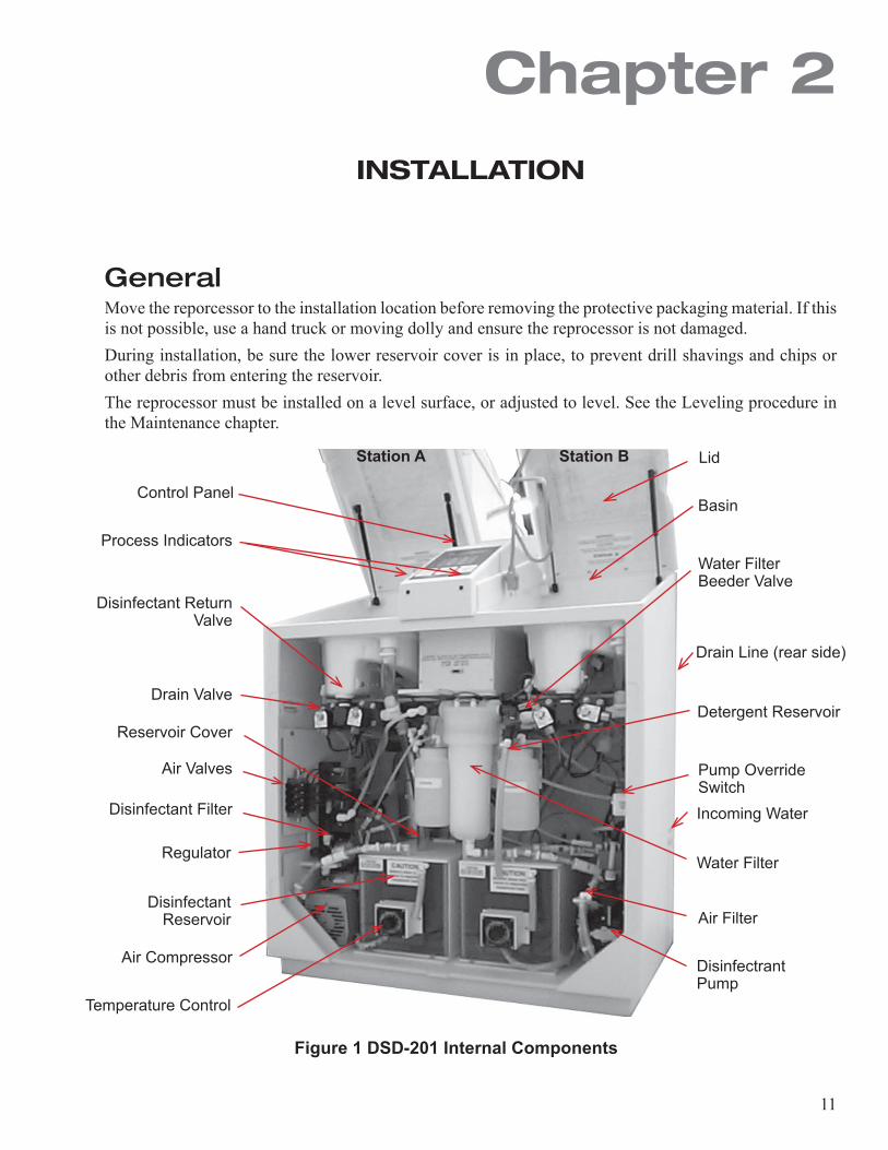
GeneralMove the reporcessor to the installation location before removing the protective packaging material. If this is not possible, use a hand truck or moving dolly and ensure the reprocessor is not damaged.During installation, be sure the lower reservoir cover is in place, to prevent drill shavings and chips or other debris from entering the reservoir.The reprocessor must be installed on a level surface, or adjusted to level. See the Leveling procedure in the Maintenance chapter.
Figure 1 DSD-201 Internal Components
Control Panel
Drain Valve
Disinfectant Return Valve
Process Indicators
Station BStation A
Air Valves
Reservoir Cover
Disinfectant Filter
Temperature Control
Disinfectant Reservoir
Regulator
Air Compressor
Lid
Water Filter Beeder Valve
Basin
Detergent Reservoir
Drain Line (rear side)
Pump Override Switch
Disinfectrant Pump
Water Filter
Incoming Water
Air Filter
12
System Supply
Water SupplyFor optimum cycle performance, the water supplied to the reprocessor must provide a flow rate of 3.2 gal/min (12 liters/min), at 35-40 psi (2.4-2.75 bar). The incoming water line must be a minimum 1/2-inch (13 mm). Use a cold water supply with a maximum temperature of 110° F (43° C).
1. Install an incoming water shut-off valve before the pre-filter system.2. Install the incoming water prefilter, supplied with the reprocessor.
• Mount the incoming water filter on the wall where it can be periodically checked for particle saturation.
Note: The filter is provided with the outlet on the right side. If the filter installation requires the outlet to be on the left side, remove the filtration brackets and reinstall on the opposite side, then loosen and rotate the gauges 180°.
3. Install the supplied water regulator between the pre-filter and the reprocessor water connection.• Incoming water pressure to the regulator must be less than 100 psi (6.8 bar).• Set the outgoing water pressure between 35-40 psi (2.4-2.75 bar).
Electrical SupplyDomestic reprocessors are supplied with a hospital grade, grounding plug that can be connected to any standard 110-130VAC outlet. International reprocessors are supplied with a standard ground- ing European plug that connects to 220-240VAC outlets.We recommend surge protectors be used for protection against power spikes and surges. The reprocessor must be plugged into or connected to a fused branched circuit.
Caution! The reprocessor does not have an on/off switch. Be sure the reprocessor is positioned so that the power cord or main circuit breaker is accessible at all times.
Warning! The reprocessor must be protectively grounded.
Air SupplyCompressed air is required (30 - 60 psi/2.1 - 4.1 bar). If you did not purchase the air compressor option with the reprocessor, be sure to make the compressed air connection to the labeled fitting on the side of the cabinet.
Warning! This air must be supplied from an oil free air source.
13
System DrainThe drain tube provided with the reprocessor consists of 36 inches of 1-inch diameter clear tub- ing. The drain tube must have 3 inches of drop (7.5 cm) or greater over the 36-inch length. Con- sult your maintenance department for multiple reprocessor installation.
Caution! The reprocessor drain relies on gravity flow. There must be no low spots in the drain line. Fluid trapped in the drain line will interfere with free drainage and reprocessor function.
Installation VerificationTo be sure that the system is ready to operate, perform a trial run with water as outlined below. Use scope hook-up to simulate an endoscope.
Caution! Operating the 120VAC reprocessor without a hook-up fitting might blow the 8-amp slow blow fuse. Operating the 230VAC reprocessor without a hook-up fitting might blow the 4-amp slow blow fuse.
1. Load the lower reservoir with water. Use the procedure described in the Operator Con- trols Chapter for loading disinfectant.
2. Fill the alcohol and detergent reservoirs, then prime the tubing.• Enter the Custom Programs menu.• Set the alcohol and detergent inject time to 15 seconds.
3. Close the lid, then press the START button.4. Check the flow through the tubing during the disinfect, air, and rinse cycles.5. Check the water regulator in the incoming water line.
• Pressure must be 35 - 40 psi (2.4 – 2.75 bar).6. Verify the cycle completes with no errors.7. Verify there are no leaks in the reprocessor.8. Press DISINFECT DUMP and START on the control panel to run a dump cycle. Refer to the “Disinfection
Dump” procedure in the Operation Chapter of this manual9. After the disinfectant dump cycle is complete, program the disinfectant soak, etc., times as needed.10. Load fresh disinfectant and begin to operate the reprocessor.
Service: If the reprocessor cannot be verified, contact MEDIVATORS Technical Support at: 1-800-444-4729 or 1-763-553-3300.

14
15
Chapter 3OPERATOR CONTROLS
GeneralThis chapter describes the operator controls, and how to set up and program the reprocessor.
16
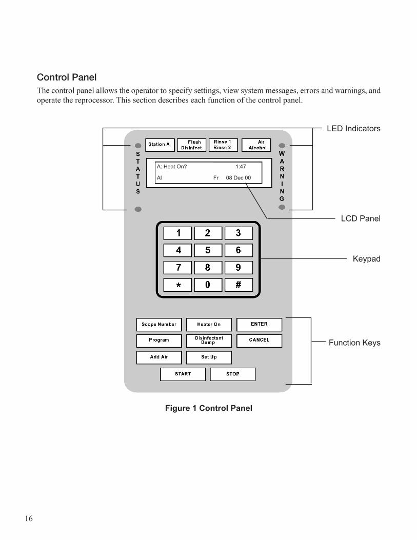
Control PanelThe control panel allows the operator to specify settings, view system messages, errors and warnings, and operate the reprocessor. This section describes each function of the control panel.
LED Indicators
LCD Panel
Keypad
Function Keys
Figure 1 Control Panel
A: Heat On? 1:47
Al Fr 08 Dec 00
17
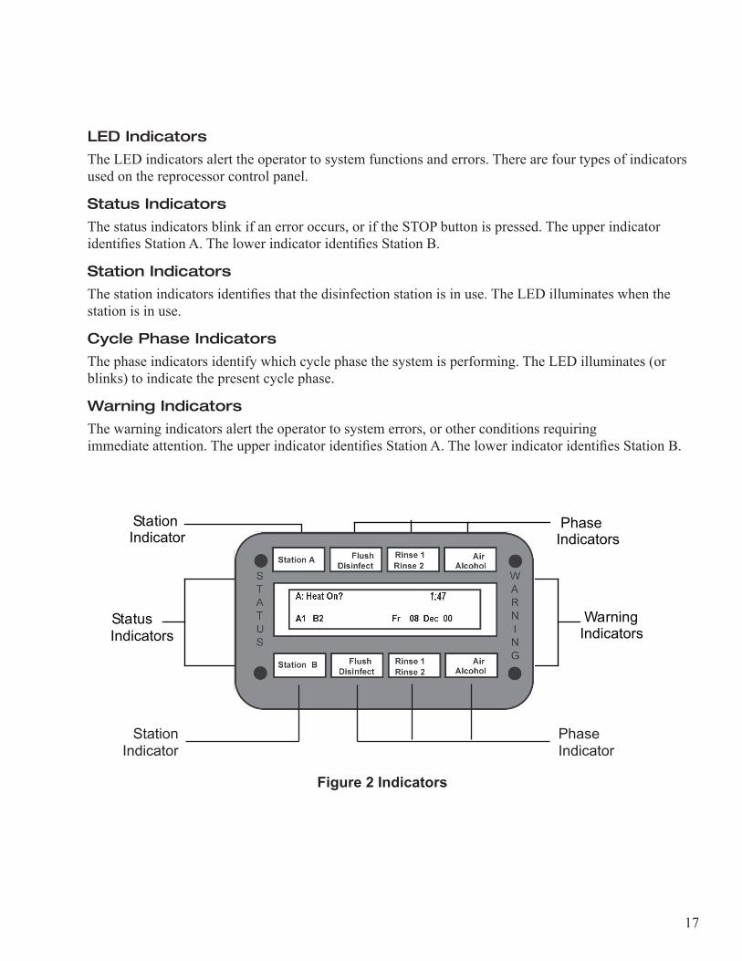
LED Indicators
The LED indicators alert the operator to system functions and errors. There are four types of indicators used on the reprocessor control panel.
Status Indicators
The status indicators blink if an error occurs, or if the STOP button is pressed. The upper indicator identifies Station A. The lower indicator identifies Station B.
Station Indicators
The station indicators identifies that the disinfection station is in use. The LED illuminates when the station is in use.
Cycle Phase Indicators
The phase indicators identify which cycle phase the system is performing. The LED illuminates (or blinks) to indicate the present cycle phase.
Warning Indicators
The warning indicators alert the operator to system errors, or other conditions requiring immediate attention. The upper indicator identifies Station A. The lower indicator identifies Station B.
Figure 2 Indicators
Warning Indicators
StatusIndicators
StationIndicator
PhaseIndicators
Station A
Flush
Disinfect
Rinse 2
Rinse 1
Alcohol
Air
A: Heat On? 1:47
A1 Fr 08 Dec 00
WARN I N G
STATUS
Station Indicator
Phase Indicator
18
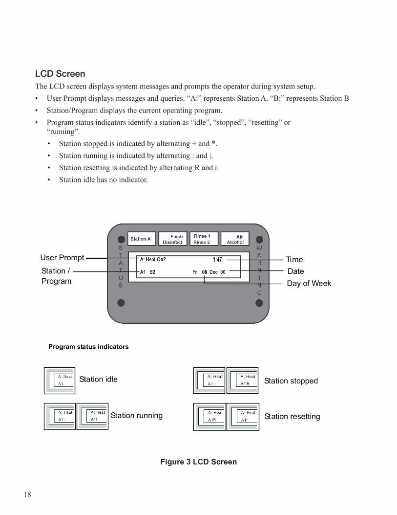
LCD ScreenThe LCD screen displays system messages and prompts the operator during system setup. • User Prompt displays messages and queries. “A:” represents Station A. “B:” represents Station B• Station/Program displays the current operating program.• Program status indicators identify a station as “idle”, “stopped”, “resetting” or
“running”.• Station stopped is indicated by alternating + and *.• Station running is indicated by alternating : and |.• Station resetting is indicated by alternating R and r.• Station idle has no indicator.
Station A
Flush
Disinfect
Rinse 2
Rinse 1
Alcohol
Air
A: Heat On? 1:47
A1 Fr 08 Dec 00TimeDate Day of Week
Station /Program
User Prompt
Station idle
Station running
Program status indicators
Station resetting
Station stopped
R r
*
|
Figure 3 LCD Screen
19
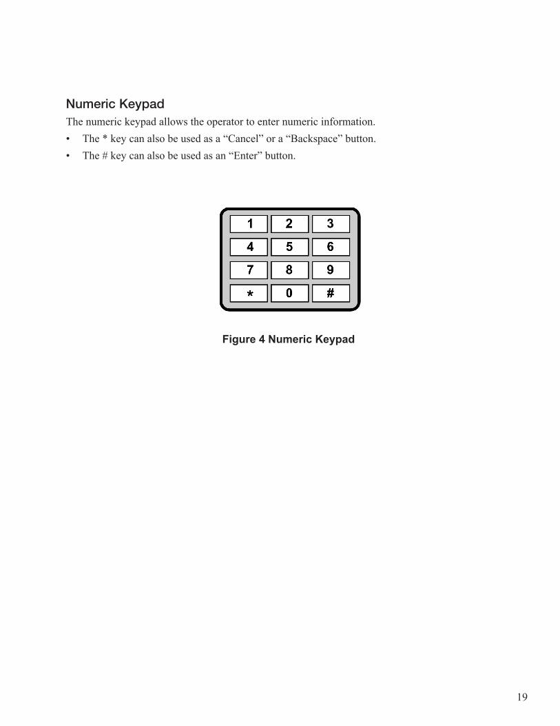
Numeric KeypadThe numeric keypad allows the operator to enter numeric information. • The * key can also be used as a “Cancel” or a “Backspace” button. • The # key can also be used as an “Enter” button.
1 2 3
4 5 6
7 8 9
*0 #
Figure 4 Numeric Keypad

20
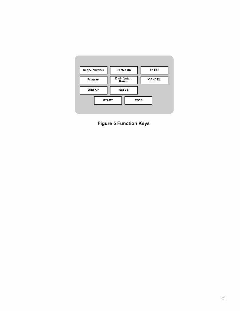
Function KeysThe function keys control the operation of the reprocessor.• ID Data
Press this button to enter the endoscope identification or serial number, operator ID number, patient ID number, and physician ID number into the log. Each ID entry can contain up to ten digits. This function is only active when the station is idle.
• Program Press this button to select a disinfection program. Enter the program number on the keypad. This function is only active when the station is idle.
• Add Air When the station is idle press this button, then the START button to air purge the scope. Otherwise, this function will append an add air cycle to the end of the currently running cycle. Pressing the button again will remove the add air cycle.
• Heater On Press this button to toggle the reservoir heater on or off. The LED illuminates when the heater is ON.
• Disinfect Dump Press this button, then the START button to dump the disinfectant. This function is only active when the station is idle.
• Set Up Press this button to access system functions.
• Enter Press this button to accept settings, or to start some system functions.
• Cancel Press this button to reject settings, reset an alarm, or abort a disinfection cycle. • Reject an incorrect user entry by pressing the CANCEL button. The previous value is restored,
or the previous screen is displayed.• Abort the currently running cycle by pressing the CANCEL button, then the ENTER button.• Reset an alarm by pressing the CANCEL button, then the ENTER button.
• Station Select Press this button to select Station A or Station B.
• Start Press this button to start a disinfection cycle or resume an interrupted cycle, or to start some system functions.
• Stop Press this button to pause a disinfection cycle, acknowledge a warning message, or stop a system function.
21
Figure 5 Function Keys
22
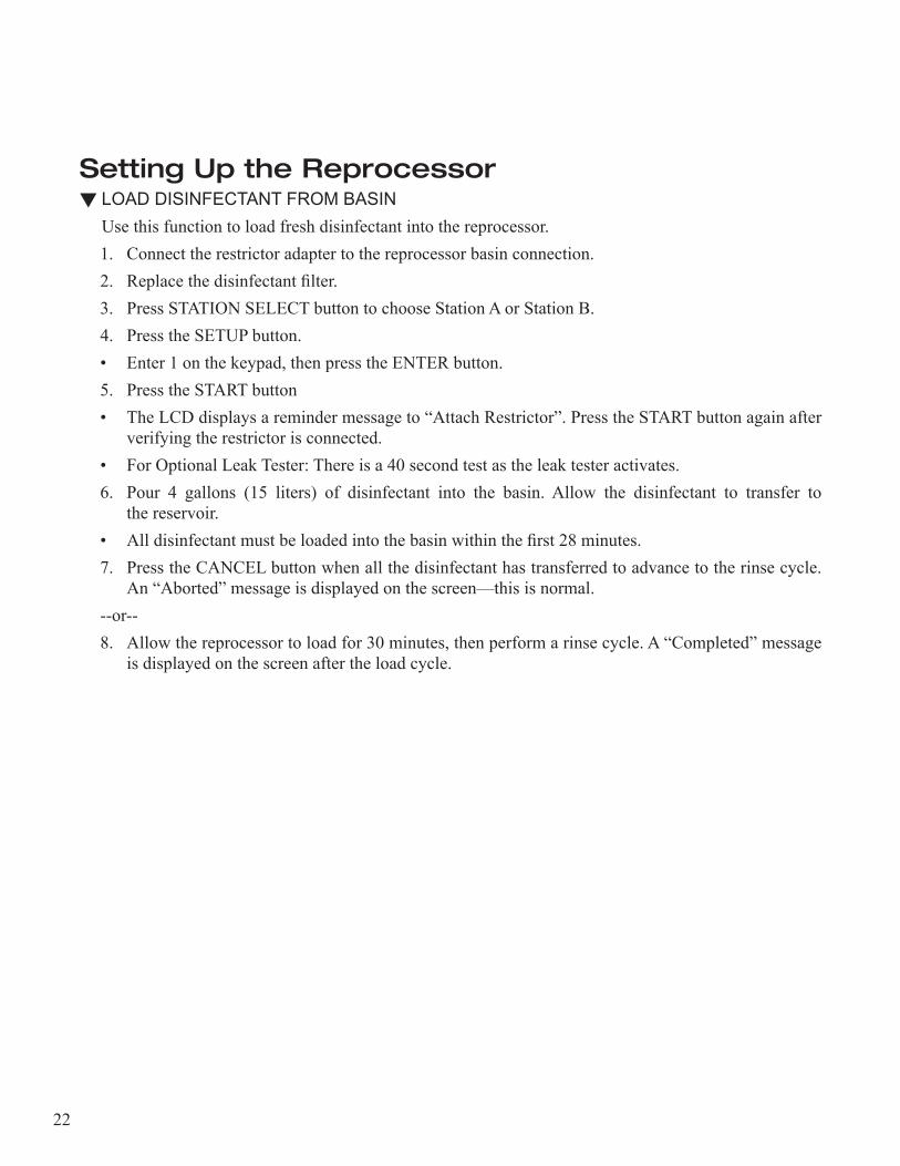
Setting Up the Reprocessor LOAD DISINFECTANT FROM BASIN
Use this function to load fresh disinfectant into the reprocessor.1. Connect the restrictor adapter to the reprocessor basin connection.2. Replace the disinfectant filter.3. Press STATION SELECT button to choose Station A or Station B.4. Press the SETUP button.• Enter 1 on the keypad, then press the ENTER button. 5. Press the START button• The LCD displays a reminder message to “Attach Restrictor”. Press the START button again after
verifying the restrictor is connected.• For Optional Leak Tester: There is a 40 second test as the leak tester activates.6. Pour 4 gallons (15 liters) of disinfectant into the basin. Allow the disinfectant to transfer to
the reservoir. • All disinfectant must be loaded into the basin within the first 28 minutes.7. Press the CANCEL button when all the disinfectant has transferred to advance to the rinse cycle.
An “Aborted” message is displayed on the screen—this is normal.--or--8. Allow the reprocessor to load for 30 minutes, then perform a rinse cycle. A “Completed” message
is displayed on the screen after the load cycle.
23
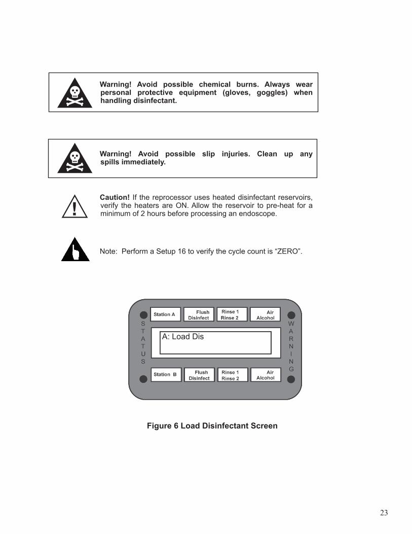
Warning! Avoid possible chemical burns. Always wear personal protective equipment (gloves, goggles) when handling disinfectant.
Warning! Avoid possible slip injuries. Clean up any spills immediately.
Caution! If the reprocessor uses heated disinfectant reservoirs, verify the heaters are ON. Allow the reservoir to pre-heat for a minimum of 2 hours before processing an endoscope.
Note: Perform a Setup 16 to verify the cycle count is “ZERO”.
Figure 6 Load Disinfectant Screen
A: Load Dis
24
LOAD DISINFECTANT WITH INTERNAL PUMP
1. Disconnect the disinfectant filter tube from the top of the reservoir.2. Replace the disinfectant filter.3. Connect the filter tube to the rigid adapter tube.4. Place the rigid end of the adapter into the disinfectant container.5. Connect the flexible adapter tube between the 3-way valve tube and the top of the reservoir
to be filled.6. Rotate the 3-way valve until it points out from the cabinet wall.7. Locate the chemical loading switch on the upper right side of the cabinet wall. Press and hold the
switch until 4 gallons (15 liters) of disinfectant is pumped into the reservoir.8. Rotate the 3-way valve back to the original position.9. Reconnect the disinfectant filler tube.
Warning! Avoid possible chemical burns. Always wear personal protective equipment (gloves, goggles) when handling disinfectant.
Warning! Avoid possible slip injuries. Clean up any spills immediately.
Note: Perform a Setup 16 to verify the cycle count is “zero”.
25
AUTOMATIC DISINFECTANT DUMP
Caution! Internal pump disinfectant dump must be used where local regulations prohibit dumping into the sanitary sewer.
1. Connect the restrictor adapter to the reprocessor basin connection.2. Press the STATION SELECT button to choose station A or staton B.3. Press the DISINFECTANT DUMP button on the control panel. The screen displays: Dump Dis4. Press the START button.
• The LCD displays a reminder message to “Attach Restrictor”. Press the START button again after verifying the restrictor is connected.
• Optional Leak Tester: There is a 40 second test as the leak tester activates. • The disinfectant is pumped into the basin and out of the drain.
5. The reprocessor performs a rinse cycle to clean the basin.6. The process indicator illuminates when the cycle is complete and the cycle counter resets to zero.
Note: The cycle count will not reset to zero if the dump procedure is canceled, or if the internal pump is used. Perform a Setup 16 to verify the cycle count has reset to zero. Perform a Setup 11 to clear the cycle count if it did not reset.
26
7. Remove the 1-inch diameter basin return tube from the lower reservoir.8. Slide the reservoir forward and wipe out with a damp lint-free cloth. Do not use paper towels.
Warnings! Avoid possible chemical burns. Always wear personal protective equipment (gloves, goggles) when handling disinfectant.
Warnings! Avoid possible burns. The disinfectant heater may be hot.
Station A
Flush
Disinfect
Rinse 2
Rinse 1
Alcohol
Air
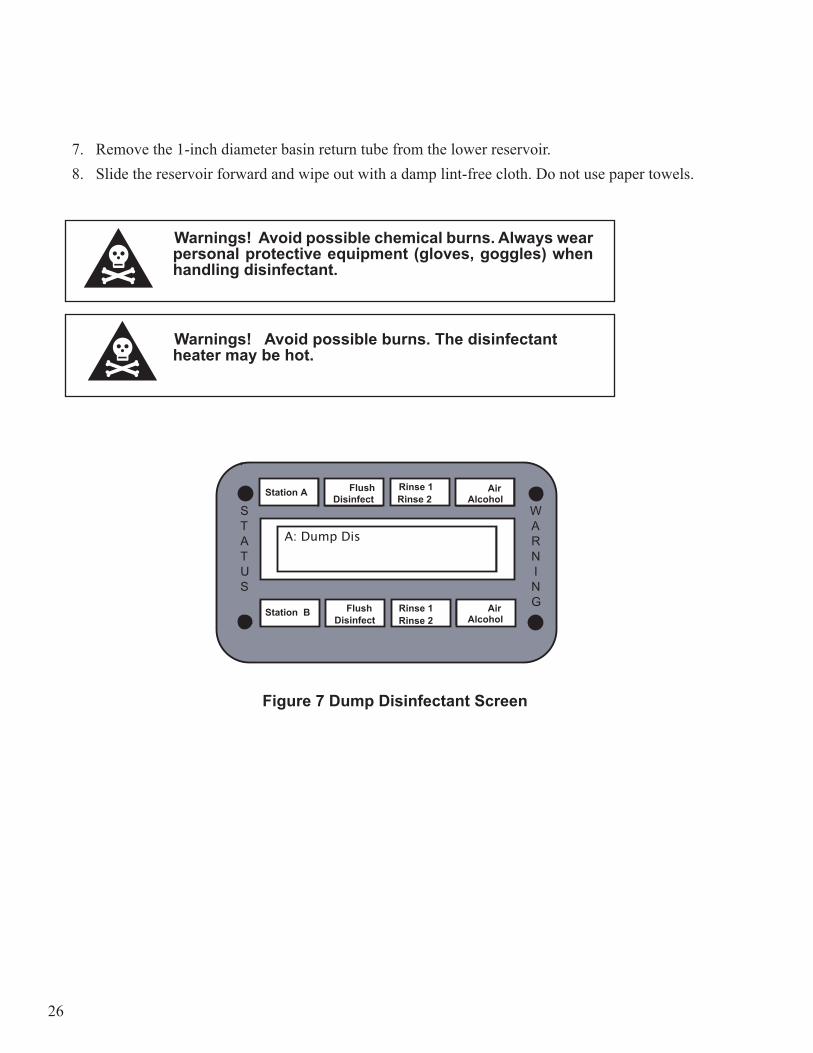
A: Dump Dis
WARN I N G
STATUS
Figure 7 Dump Disinfectant Screen
Disinfect
Station A Flush Disinfect Rinse 2
Rinse 1 Alcohol Air
A: Dump Dis
WARN I N G
STATUS
Station B Rinse 1 Alcohol Air
Rinse 2 Flush
27
DUMP DISINFECTANT WITH INTERNAL PUMP
Caution! The internal disinfectant pump must be used manually where local regulations prohibit dumping into the sanitary sewer.
1. Connect the rigid adapter hose to the 3-way disinfectant valve.2. Rotate the valve handle until it points out from the wall of the cabinet.3. Place the free end of the adapter hose into an appropriate container.4. Connect the pump inlet to the reservoir (use the flex adapter, if necessary).5. Locate the chemical loading switch on the upper right side of the cabinet wall. Press and hold the
switch until all the disinfectant is pumped from the reservoir. 6. Disconnect the rigid adapter hose and rotate the 3-way valve back to the original position.7. Remove the 1-inch diameter basin return tube from the lower reservoir. Slide the reservoir forward and
wipe out with a damp lint-free cloth. Do not use paper towels.8. Reconnect the pump inlet hose to the reservoir. Perform a Setup 11 to clear the cycle count. Perform a
Setup 16 to verify that the cycle count resets to zero.
28
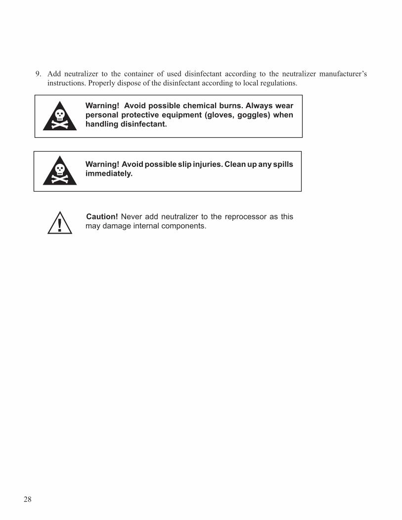
9. Add neutralizer to the container of used disinfectant according to the neutralizer manufacturer’s instructions. Properly dispose of the disinfectant according to local regulations.
Warning! Avoid possible chemical burns. Always wear personal protective equipment (gloves, goggles) when handling disinfectant.
Warning! Avoid possible slip injuries. Clean up any spills immediately.
Caution! Never add neutralizer to the reprocessor as this may damage internal components.
29
SET THE DATE
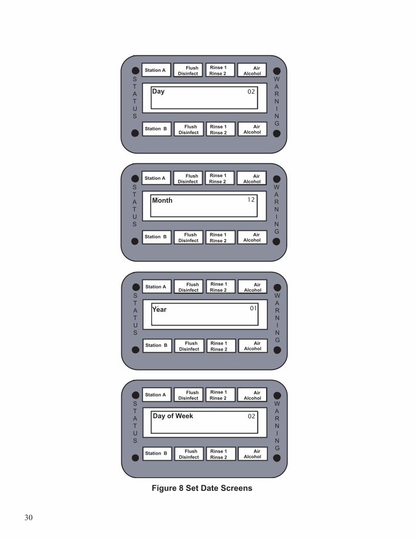
Use this function to set the system date. This setting changes both the control panel display and the internal system clock.1. Press the SETUP button. 2. Enter 2 on the keypad, then press the ENTER button.3. Change the day setting.
• Enter the correct two-digit day (01-31).• Press the ENTER button.
4. Change the month setting.• Enter the correct two-digit month (01-12).• Press the ENTER button.• The month is displayed as three alpha characters (Jan, Feb, etc.) in Run mode.
5. Change the year setting.• Enter the correct two-digit year (00-99).• Press the ENTER button.
6. Change the day of the week setting.• Enter the correct day (1-7, Sunday is 1).• Press the ENTER button.• The day of the week is displayed as two alpha characters (Su, Mo, etc.) in Run mode.
Note: Press the SETUP button at any time to exit the function.
30
Station A
Flush
Disinfect
Rinse 2
Rinse 1
Alcohol
Air
Day 02
WARN I N G
STATUS
Station A
Flush
Disinfect
Rinse 2
Rinse 1
Alcohol
Air
Month 12
WARN I N G
STATUS
Station A
Flush
Disinfect
Rinse 2
Rinse 1
Alcohol
Air
Year 01
WARN I N G
STATUS
Station A
Flush
Disinfect
Rinse 2
Rinse 1
Alcohol
Air
Day of Week 02
WARN I N G
STATUS
Figure 8 Set Date Screens
Disinfect
Station A Flush Disinfect Rinse 2
Rinse 1 Alcohol Air
Day�� 02
WARN I N G
STATUS
Station B Rinse 1 Alcohol Air
Rinse 2 Flush
Disinfect
Station A Flush Disinfect Rinse 2
Rinse 1 Alcohol Air
Month�� 12
WARN I N G
STATUS
Station B Rinse 1 Alcohol Air
Rinse 2 Flush
Disinfect
Station A Flush Disinfect Rinse 2
Rinse 1 Alcohol Air
Year �� 01
WARN I N G
STATUS
Station B Rinse 1 Alcohol Air
Rinse 2 Flush
Disinfect
Station A Flush Disinfect Rinse 2
Rinse 1 Alcohol Air
Day of Week� 02
WARN I N G
STATUS
Station B Rinse 1 Alcohol Air
Rinse 2 Flush
Day
Month
Year
Day of Week

31
SET THE TIME
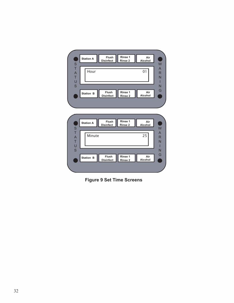
Use this function to set the system time. This setting changes the display and the internal system clock. Verify the clock setting daily to ensure accuracy.1. Press the SETUP button. 2. Enter 3 on the keypad, then press the ENTER button.3. Change the hour setting.
• Enter the correct two-digit hour (00-23, midnight is 00).• Press the ENTER button.
4. Change the minute setting.• Enter the correct two-digit minute (00-59).• Press the ENTER button.
Note: Press the SETUP button at any time to exit the function.
32
Station A
Flush
Disinfect
Rinse 2
Rinse 1
Alcohol
Air
Hour 01
WARN I N G
STATUS
Station A
Flush
Disinfect
Rinse 2
Rinse 1
Alcohol
Air
Minute 25
WARN I N G
STATUS
Figure 9 Set Time Screens
Disinfect
Station A Flush Disinfect Rinse 2
Rinse 1 Alcohol Air
Hour�� 01
WARN I N G
STATUS
Station B Rinse 1 Alcohol Air
Rinse 2 Flush
Disinfect
Station A Flush Disinfect Rinse 2
Rinse 1 Alcohol Air
Minute�� 25
WARN I N G
STATUS
Station B Rinse 1 Alcohol Air
Rinse 2 Flush
33
Disinfect
Station A Flush Disinfect Rinse 2
Rinse 1 Alcohol Air
Software Version
X3.0�� V3.0
WARN I N G
STATUS
Station B Rinse 1 Alcohol Air
Rinse 2 Flush
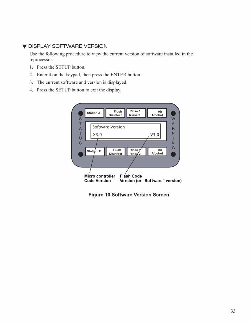
DISPLAY SOFTWARE VERSION
Use the following procedure to view the current version of software installed in the reprocessor.1. Press the SETUP button. 2. Enter 4 on the keypad, then press the ENTER button.3. The current software and version is displayed.4. Press the SETUP button to exit the display.
Station A
Flush
Disinfect
Rinse 2
Rinse 1
Alcohol
Air
Software Version
V3.0 V3.0
WARN I N G
STATUS
Micro controller Flash CodeCode Version Version (or “Software” version)
Figure 10 Software Version Screen
34
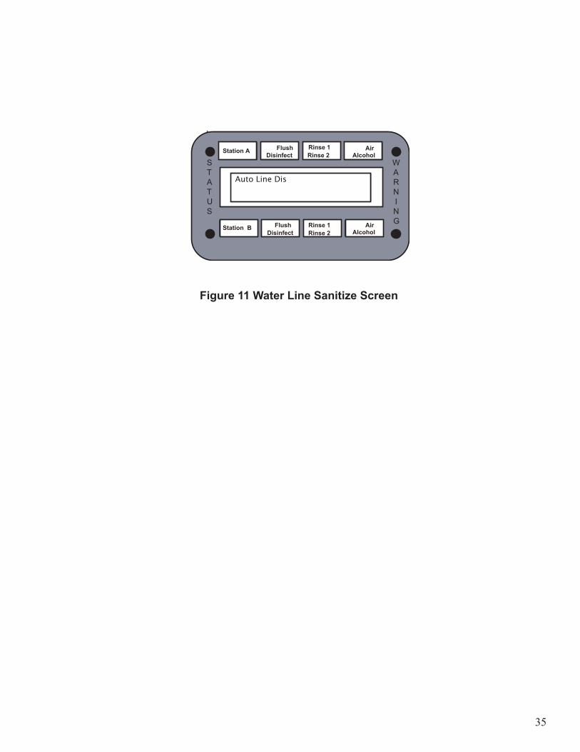
WATER LINE SANITIZEThis function sanitizes the water lines in the reprocessor. This procedure must be performed after each water filter change and after any service is performed on the water supply system.
Caution! Ensure the restrictor adapter provided with the installation kit is connected in the basin before performing this procedure.
1. Verify station is idle before performing this procedure. The default sanitization time is one (1) hour.
Caution! High level disinfectants and sterilants with high level disinfectant contact times exceeding 3 hours or sterilant claims exceeding 10 hours must not be used for water line and filter high level disinfection or sterilization
2. Press the SETUP button.• Enter 6 on the keypad, then press the ENTER button.
3. Press the START button. • The LCD displays a reminder message to “Attach Restrictor”. Press the START button again after
verifying the restrictor is connected.• The disinfectant will remain in the lines for the pre-programmed water line sanitization time.
Note: Use Diagnostics 69 to change the amount of time the disinfectant remains in the water lines.
4. After the sanitizing procedure is complete, add approximately 1 gallon (4 liters) of fresh disinfectant to fill the reservoir to the proper level.
35
Station A
Flush
Disinfect
Rinse 2
Rinse 1
Alcohol
Air
Auto Line Dis
WARN I N G
STATUS
Figure 11 Water Line Sanitize Screen
Disinfect
Station A Flush Disinfect Rinse 2
Rinse 1 Alcohol Air
Auto Line Dis
WARN I N G
STATUS
Station B Rinse 1 Alcohol Air
Rinse 2 Flush
36
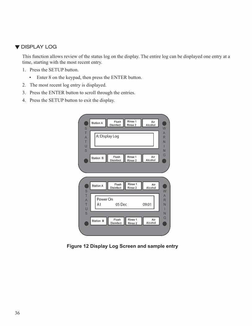
DISPLAY LOG
This function allows review of the status log on the display. The entire log can be displayed one entry at a time, starting with the most recent entry.1. Press the SETUP button.
• Enter 8 on the keypad, then press the ENTER button.2. The most recent log entry is displayed. 3. Press the ENTER button to scroll through the entries.4. Press the SETUP button to exit the display.
Station A
Flush
Disinfect
Rinse 2
Rinse 1
Alcohol
Air
Power On
A1 05 Dec 09:01
WARN I N G
STATUS
Station A
Flush
Disinfect
Rinse 2
Rinse 1
Alcohol
Air
A: Display Log
WARN I N G
STATUS
Figure 12 Display Log Screen and sample entry
37
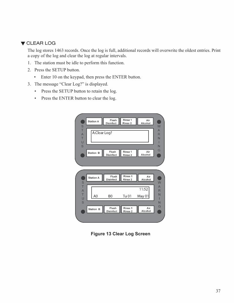
CLEAR LOG
The log stores 1463 records. Once the log is full, additional records will overwrite the oldest entries. Print a copy of the log and clear the log at regular intervals.1. The station must be idle to perform this function.2. Press the SETUP button.
• Enter 10 on the keypad, then press the ENTER button.3. The message “Clear Log?” is displayed.
• Press the SETUP button to retain the log.• Press the ENTER button to clear the log.
Station A
Flush
Disinfect
Rinse 2
Rinse 1
Alcohol
Air
A:Clear Log?
WARN I N G
STATUS
Figure 13 Clear Log Screen
38
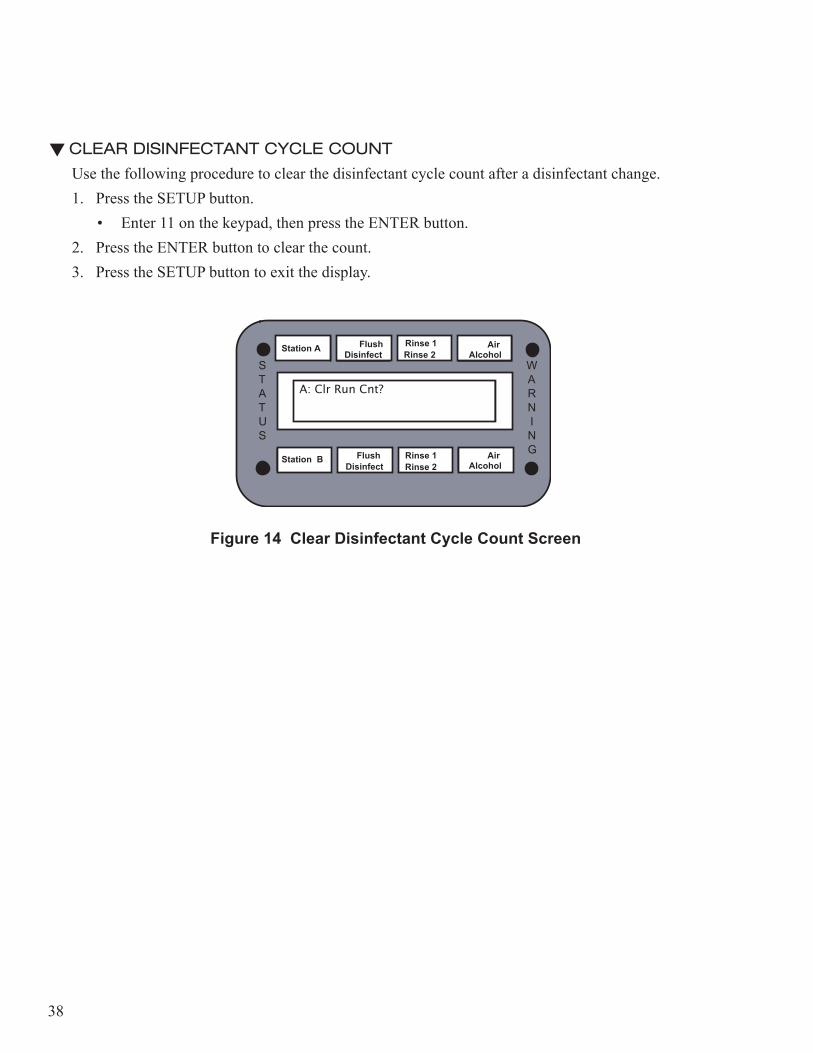
CLEAR DISINFECTANT CYCLE COUNT
Use the following procedure to clear the disinfectant cycle count after a disinfectant change.1. Press the SETUP button.
• Enter 11 on the keypad, then press the ENTER button.2. Press the ENTER button to clear the count.3. Press the SETUP button to exit the display.
Station A
Flush
Disinfect
Rinse 2
Rinse 1
Alcohol
Air
A: Clr Run Cnt?
WARN I N G
STATUS
Figure 14 Clear Disinfectant Cycle Count Screen
Disinfect
Station A Flush Disinfect Rinse 2
Rinse 1 Alcohol Air
A: Clr Run Cnt?
WARN I N G
STATUS
Station B Rinse 1 Alcohol Air
Rinse 2 Flush
39
Programming the Reprocessor
INPUT PROGRAM
Custom programs allow the operator to change the cycle parameter settings to accommodate various disinfectant solutions, or to setup custom reprocessing protocols. A maximum of nine custom programs can be pre-set. Refer to the disinfection cycle chart in the appendix for range settings.
Depending on selections, some of the following screens will not be displayed.
To deactivate a phase, enter “0” for the time setting, then press the ENTER button.
1. Press the SETUP button.• Enter 5 on the keypad, then press the ENTER button.
2. The “Program 1” screen is displayed. Enter the program digit (1-9) on the numeric keypad, then press the ENTER button.
3. The “Soak” screen is displayed. Enter the desired soak time.• Enter two digits for the minutes, then press ENTER.• Enter two digits for the seconds, then press ENTER.
4. The “Soak Rinse” screen is displayed. Enter the desired soak rinse time. • Enter two digits for the minutes, then press ENTER.• Enter two digits for the seconds, then press ENTER.
5. The “Flush” screen is displayed. Enter the desired detergent flush time.• Enter two digits for the minutes, then press ENTER.• Enter two digits for the seconds, then press ENTER.

40
Station A
Flush
Disinfect
Rinse 2
Rinse 1
Alcohol
Air
P1 Soak
Set Minutes 00:00
WARN I N G
STATUS
Station A
Flush
Disinfect
Rinse 2
Rinse 1
Alcohol
Air
P1 Soak Rinse
Set Minutes 00:00
WARN I N G
STATUS
Station A
Flush
Disinfect
Rinse 2
Rinse 1
Alcohol
Air
P1Flush
Set Minutes 00:00
WARN I N G
STATUS
Figure 15 Custom Program Setup Screens
Disinfect
Station A Flush Disinfect Rinse 2
Rinse 1 Alcohol Air
P1 SoakSet Minutes� 00:00
WARN I N G
STATUS
Station B Rinse 1 Alcohol Air
Rinse 2 Flush
Disinfect
Station A Flush Disinfect Rinse 2
Rinse 1 Alcohol Air
P1 Soak RinseSet Minutes� 00:00
WARN I N G
STATUS
Station B Rinse 1 Alcohol Air
Rinse 2 Flush
Disinfect
Station A Flush Disinfect Rinse 2
Rinse 1 Alcohol Air
P1 FlushSet Minutes� 00:00
WARN I N G
STATUS
Station B Rinse 1 Alcohol Air
Rinse 2 Flush

41
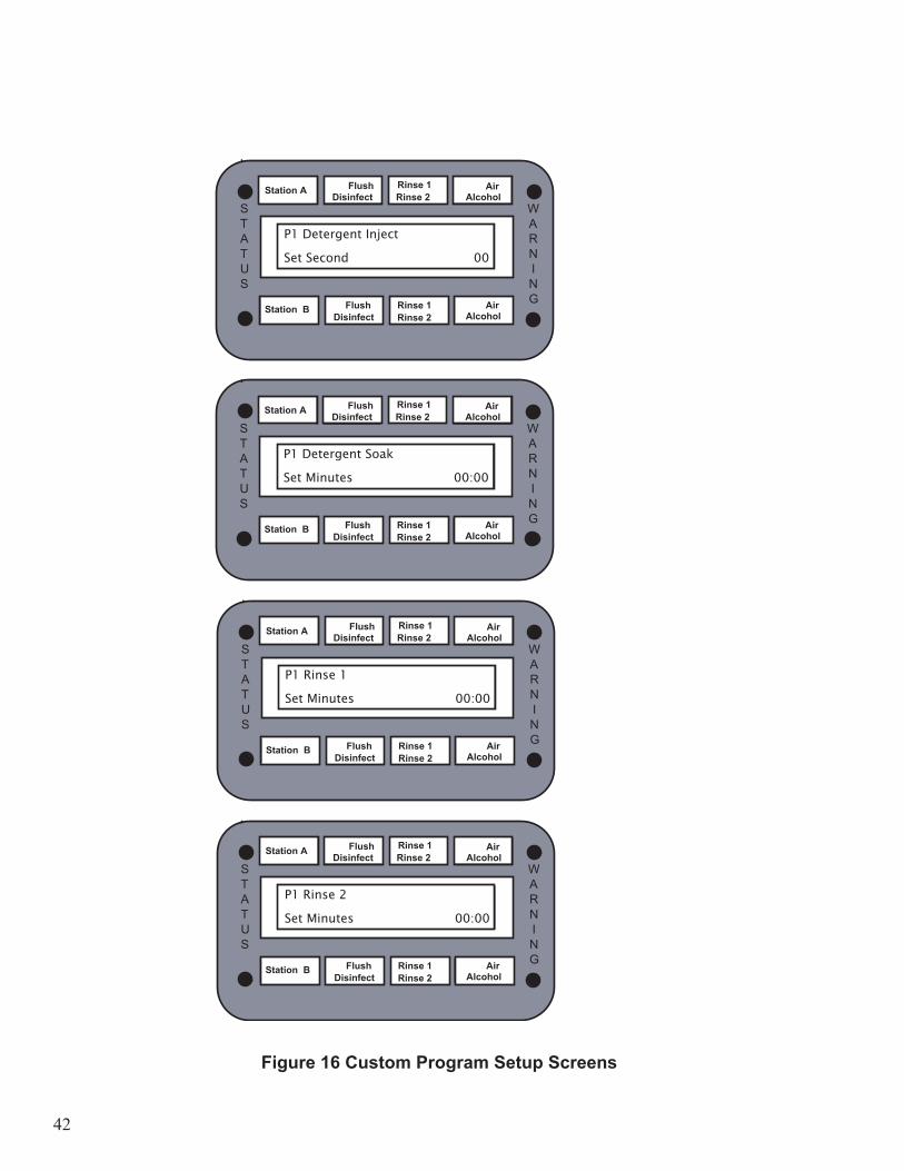
6. The “Detergent Inject” screen is displayed. Enter the desired detergent inject time. The volume of detergent is controlled by the number of seconds entered on the screen, up to a maximum of 59 seconds.
Inject Time Volume to Inject Soak Dilution Rate (not correct for flush)
1 second = 3mL detergent solution
= 0.033 oz/gal. = 0.26 mL/litre
• Enter two digits for the seconds, then press ENTER.7. The “Dis Soak” screen is displayed. Enter the desired disinfectant soak time.
• Enter two digits for the minutes, then press ENTER.• Enter two digits for the seconds, then press ENTER.
8. The “Rinse 1” screen is displayed. Enter the desired primary rinse time. • Enter two digits for the minutes, then press ENTER.• Enter two digits for the seconds, then press ENTER.
9. The “Rinse 2” screen is displayed. Enter the desired secondary rinse time. • Enter two digits for the minutes, then press ENTER.• Enter two digits for the seconds, then press ENTER.
10. The “Rinse 3” screen is displayed. Enter the desired rinse time. • Enter two digits for the minutes, then press ENTER.• Enter two digits for the seconds, then press ENTER.
42
Station A
Flush
Disinfect
Rinse 2
Rinse 1
Alcohol
Air
P1Rinse 1
Set Minutes 00:00
WARN I N G
STATUS
Station A
Flush
Disinfect
Rinse 2
Rinse 1
Alcohol
Air
P1Rinse 2Set Minutes 00:00
WARN I N G
STATUS
Station A
Flush
Disinfect
Rinse 2
Rinse 1
Alcohol
Air
P1Disinfectant Soak
Set Minutes 00:00
WARN I N G
STATUS
Station A
Flush
Disinfect
Rinse 2
Rinse 1
Alcohol
Air
P1Detergent Inject
Set Seconds 00
WARN I N G
STATUS
Figure 16 Custom Program Setup Screens
Disinfect
Station A Flush Disinfect Rinse 2
Rinse 1 Alcohol Air
P1 Detergent Inject
Set Second�� 00
WARN I N G
STATUS
Station B Rinse 1 Alcohol Air
Rinse 2 Flush
Disinfect
Station A Flush Disinfect Rinse 2
Rinse 1 Alcohol Air
P1 Detergent Soak
Set Minutes� 00:00
WARN I N G
STATUS
Station B Rinse 1 Alcohol Air
Rinse 2 Flush
Disinfect
Station A Flush Disinfect Rinse 2
Rinse 1 Alcohol Air
P1 Rinse 1
Set Minutes� 00:00
WARN I N G
STATUS
Station B Rinse 1 Alcohol Air
Rinse 2 Flush
Disinfect
Station A Flush Disinfect Rinse 2
Rinse 1 Alcohol Air
P1 Rinse 2
Set Minutes� 00:00
WARN I N G
STATUS
Station B Rinse 1 Alcohol Air
Rinse 2 Flush

43
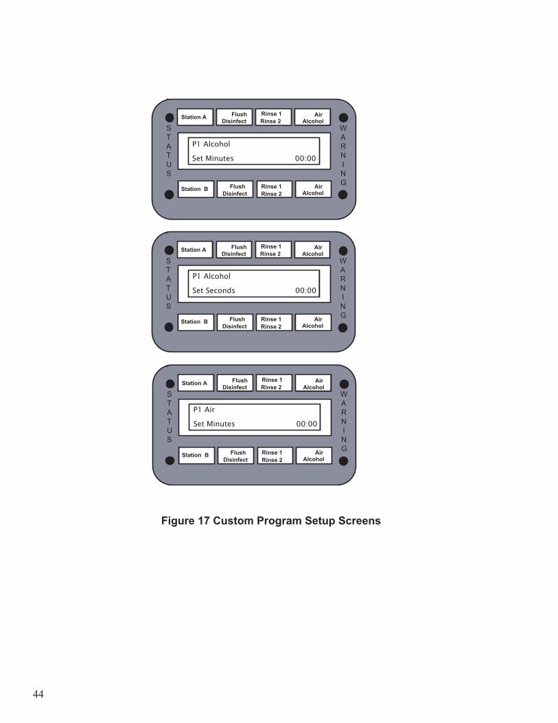
11. The “Alcohol” screen is displayed. Enter the alcohol purge time.• Enter two digits for the minutes, then press ENTER.• Enter two digits for the seconds, then press ENTER.12. The “Alcohol Inject” screen is displayed. Enter the alcohol inject time. The volume of alcohol is
controlled by the number of seconds entered on the screen, up to a maximum of 59 seconds.
Inject Time Volume to Inject1 second injection = 3cc alcohol
13. The “Air” screen is displayed. Enter the desired air cycle time.• Enter two digits for the minutes, then press ENTER.• Enter two digits for the seconds, then press ENTER.14. The custom program setting is complete. Record the settings in the appendix for future reference (see
the Custom Program Reference Chart).
Note: Press the STOP button at any time to exit the Custom Disinfection Program setup function.
44
Station A
Flush
Disinfect
Rinse 2
Rinse 1
Alcohol
Air
P1Alcohol
Set Minutes 00:00
WARN I N G
STATUS
Station A
Flush
Disinfect
Rinse 2
Rinse 1
Alcohol
Air
P1Alcohol Inject
Set Seconds 00
WARN I N G
STATUS
Station A
Flush
Disinfect
Rinse 2
Rinse 1
Alcohol
Air
P1Air
Set Minutes 00:00
WARN I N G
STATUS
Figure 17 Custom Program Setup Screens
Disinfect
Station A Flush Disinfect Rinse 2
Rinse 1 Alcohol Air
WARN I N G
STATUS
Station B Rinse 1 Alcohol Air
Rinse 2 Flush
Disinfect
Station A Flush Disinfect Rinse 2
Rinse 1 Alcohol Air
P1 Alcohol
Set Seconds� 00:00
WARN I N G
STATUS
Station B Rinse 1 Alcohol Air
Rinse 2 Flush
Disinfect
Station A Flush Disinfect Rinse 2
Rinse 1 Alcohol Air
P1 Air
Set Minutes� 00:00
WARN I N G
STATUS
Station B Rinse 1 Alcohol Air
Rinse 2 Flush
P1 Alcohol
Set Minutes� 00:00
45
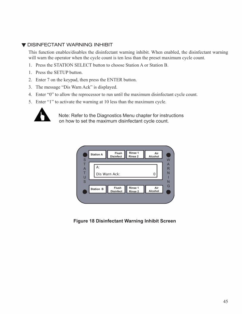
DISINFECTANT WARNING INHIBIT
This function enables/disables the disinfectant warning inhibit. When enabled, the disinfectant warning will warn the operator when the cycle count is ten less than the preset maximum cycle count.1. Press the STATION SELECT button to choose Station A or Station B.1. Press the SETUP button.2. Enter 7 on the keypad, then press the ENTER button.3. The message “Dis Warn Ack” is displayed. 4. Enter “0” to allow the reprocessor to run until the maximum disinfectant cycle count.5. Enter “1” to activate the warning at 10 less than the maximum cycle.
Note: Refer to the Diagnostics Menu chapter for instructions on how to set the maximum disinfectant cycle count.
Station A
Flush
Disinfect
Rinse 2
Rinse 1
Alcohol
Air
A:Dis Warn Ack: 0
WARN I N G
STATUS
Figure 18 Disinfectant Warning Inhibit Screen
Disinfect
Station A Flush Disinfect Rinse 2
Rinse 1 Alcohol Air
A:
Dis Warn Ack:�� 0
WARN I N G
STATUS
Station B Rinse 1 Alcohol Air
Rinse 2 Flush

46
DISPLAY TEMPERATURES
Use the following procedure to view the temperatures.1. Press the SETUP button.
• Enter 13 on the keypad, then press the ENTER button.2. The temperatures are displayed in Celsius.3. Press the SETUP button to exit the display.
Station A
Flush
Disinfect
Rinse 2
Rinse 1
Alcohol
Air
A: 35.2 38.1
WARN I N G
STATUS
Basin Reservoir
Figure 19 Display Temperatures Screen
Disinfect
Station A Flush Disinfect Rinse 2
Rinse 1 Alcohol Air
A: 35.2� 38.1
B: 35.2� 38.1
WARN I N G
STATUS
Station B Rinse 1 Alcohol Air
Rinse 2 Flush
47
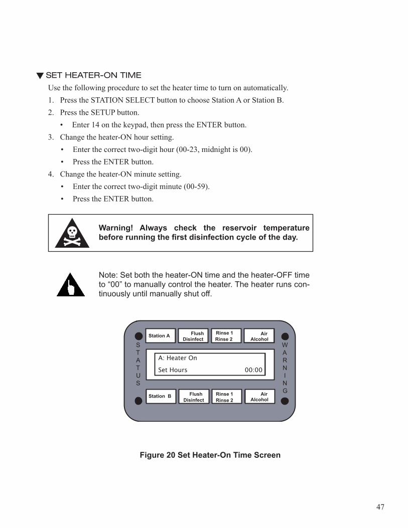
SET HEATER-ON TIME
Use the following procedure to set the heater time to turn on automatically. 1. Press the STATION SELECT button to choose Station A or Station B.2. Press the SETUP button.
• Enter 14 on the keypad, then press the ENTER button.3. Change the heater-ON hour setting.
• Enter the correct two-digit hour (00-23, midnight is 00).• Press the ENTER button.
4. Change the heater-ON minute setting.• Enter the correct two-digit minute (00-59).• Press the ENTER button.
Warning! Always check the reservoir temperature before running the first disinfection cycle of the day.
Note: Set both the heater-ON time and the heater-OFF time to “00” to manually control the heater. The heater runs con-tinuously until manually shut off.
Station A
Flush
Disinfect
Rinse 2
Rinse 1
Alcohol
Air
A: Heater On
Set Hours 00:00
WARN I N G
STATUS
Figure 20 Set Heater-On Time Screen
Disinfect
Station A Flush Disinfect Rinse 2
Rinse 1 Alcohol Air
A: Heater On
Set Hours�� 00:00
WARN I N G
STATUS
Station B Rinse 1 Alcohol Air
Rinse 2 Flush
48
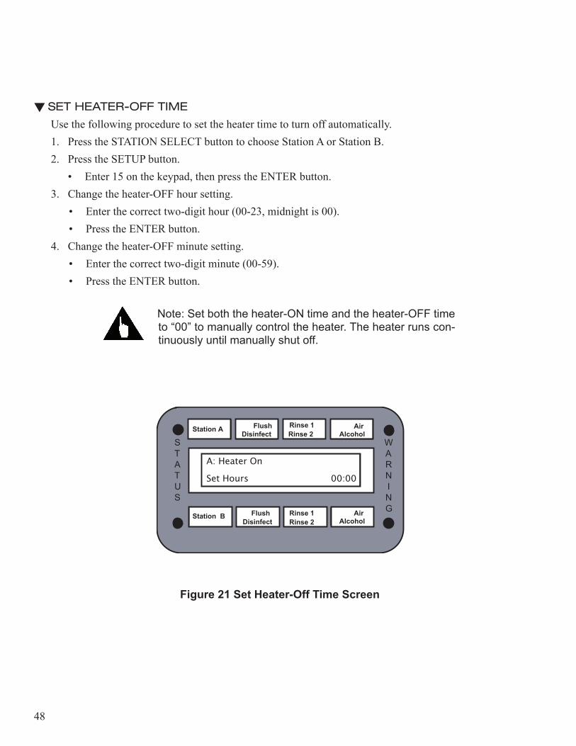
SET HEATER-OFF TIME
Use the following procedure to set the heater time to turn off automatically.1. Press the STATION SELECT button to choose Station A or Station B.2. Press the SETUP button.
• Enter 15 on the keypad, then press the ENTER button.3. Change the heater-OFF hour setting.
• Enter the correct two-digit hour (00-23, midnight is 00).• Press the ENTER button.
4. Change the heater-OFF minute setting.• Enter the correct two-digit minute (00-59).• Press the ENTER button.
Note: Set both the heater-ON time and the heater-OFF time to “00” to manually control the heater. The heater runs con-tinuously until manually shut off.
Station A
Flush
Disinfect
Rinse 2
Rinse 1
Alcohol
Air
A: Heater Off
Set Hours 00:00
WARN I N G
STATUS
Figure 21 Set Heater-Off Time Screen
Disinfect
Station A Flush Disinfect Rinse 2
Rinse 1 Alcohol Air
A: Heater On
Set Hours�� 00:00
WARN I N G
STATUS
Station B Rinse 1 Alcohol Air
Rinse 2 Flush

49
DISPLAY DISINFECTANT CYCLE COUNT
Use the following procedure to view the disinfectant cycle count.1. Press the SETUP button.
• Enter 16 on the keypad, then press the ENTER button.2. The disinfectant cycle count is displayed3. Press the SETUP button to exit the display.
Station A
Flush
Disinfect
Rinse 2
Rinse 1
Alcohol
Air
Dis Cycle Count
A: 000
WARN I N G
STATUS
Figure 22 Disinfectant Cycle Count Screen
Disinfect
Station A Flush Disinfect Rinse 2
Rinse 1 Alcohol Air
Dis Cycle Count
A: 000� B: 000
WARN I N G
STATUS
Station B Rinse 1 Alcohol Air
Rinse 2 Flush
50
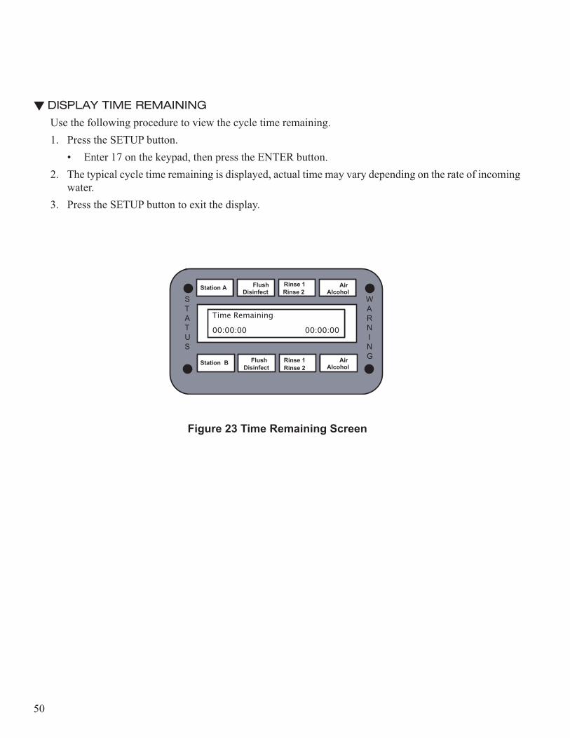
DISPLAY TIME REMAINING
Use the following procedure to view the cycle time remaining.1. Press the SETUP button.
• Enter 17 on the keypad, then press the ENTER button.2. The typical cycle time remaining is displayed, actual time may vary depending on the rate of incoming
water.3. Press the SETUP button to exit the display.
Station A
Flush
Disinfect
Rinse 2
Rinse 1
Alcohol
Air
Time Remaining
00:00:00
WARN I N G
STATUS
Figure 23 Time Remaining Screen
Disinfect
Station A Flush Disinfect Rinse 2
Rinse 1 Alcohol Air
Time Remaining
00:00:00�� 00:00:00
WARN I N G
STATUS
Station B Rinse 1 Alcohol Air
Rinse 2 Flush

51
DISPLAY STATE TIME
A cycle is comprised of a number of states. Use the following procedure to view the state time.1. Press the SETUP button.
• Enter 18 on the keypad, then press the ENTER button.2. The current state number and time remaining is displayed3. Press the SETUP button to exit the display.
Note: Refer to the Disinfection Cycle Chart in the Appendix for state times.
Station A
Flush
Disinfect
Rinse 2
Rinse 1
Alcohol
Air
State Time Display
000/00:00
WARN I N G
STATUS
Figure 24 State Time Screen
Disinfect
Station A Flush Disinfect Rinse 2
Rinse 1 Alcohol Air
State Time Display
000/00:00�� 000/00:00
WARN I N G
STATUS
Station B Rinse 1 Alcohol Air
Rinse 2 Flush
52
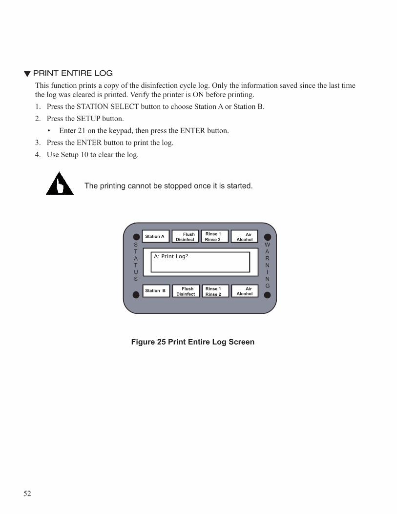
PRINT ENTIRE LOG
This function prints a copy of the disinfection cycle log. Only the information saved since the last time the log was cleared is printed. Verify the printer is ON before printing.1. Press the STATION SELECT button to choose Station A or Station B.2. Press the SETUP button.
• Enter 21 on the keypad, then press the ENTER button.3. Press the ENTER button to print the log.4. Use Setup 10 to clear the log.
The printing cannot be stopped once it is started.
Station A
Flush
Disinfect
Rinse 2
Rinse 1
Alcohol
Air
A: Print Log?
WARN I N G
STATUS
Figure 25 Print Entire Log Screen
Disinfect
Station A Flush Disinfect Rinse 2
Rinse 1 Alcohol Air
A: Print Log?
WARN I N G
STATUS
Station B Rinse 1 Alcohol Air
Rinse 2 Flush
53
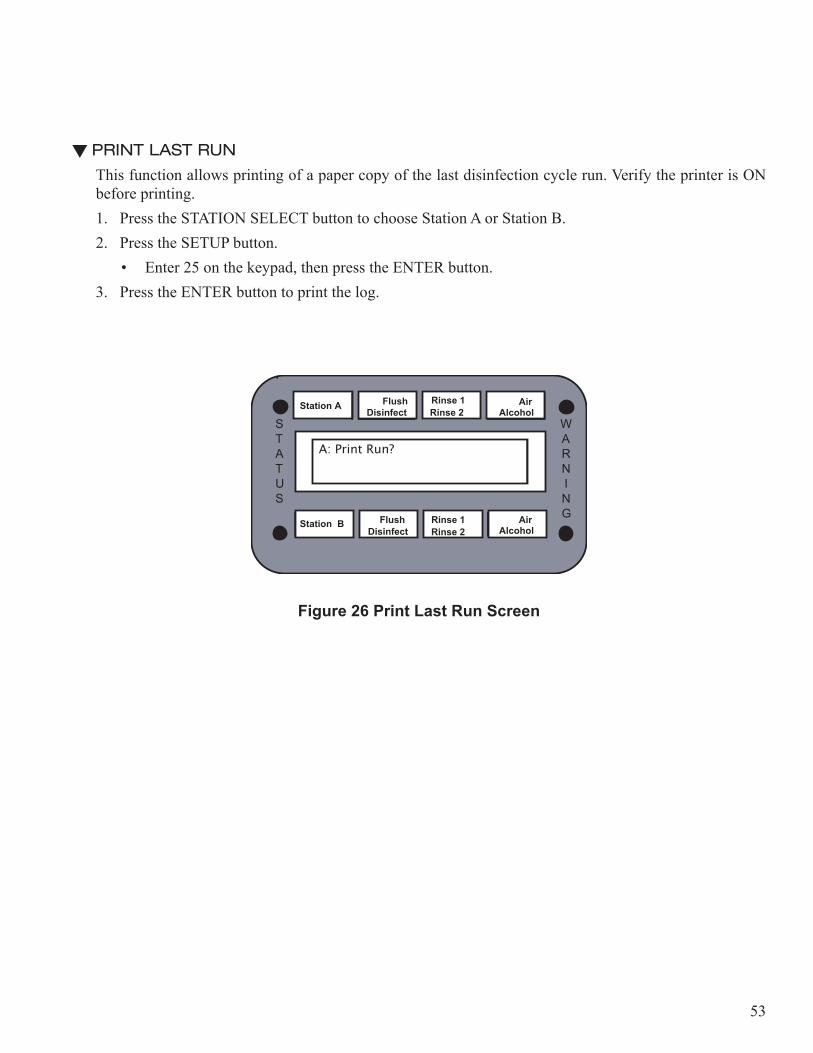
PRINT LAST RUN
This function allows printing of a paper copy of the last disinfection cycle run. Verify the printer is ON before printing.1. Press the STATION SELECT button to choose Station A or Station B.2. Press the SETUP button.
• Enter 25 on the keypad, then press the ENTER button.3. Press the ENTER button to print the log.
Station A
Flush
Disinfect
Rinse 2
Rinse 1
Alcohol
Air
A: Print Run?
WARN I N G
STATUS
Figure 26 Print Last Run Screen
Disinfect
Station A Flush Disinfect Rinse 2
Rinse 1 Alcohol Air
A: Print Run?
WARN I N G
STATUS
Station B Rinse 1 Alcohol Air
Rinse 2 Flush
54
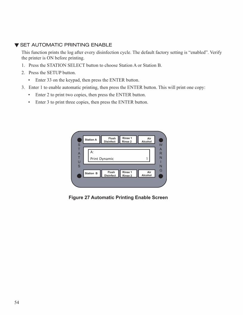
SET AUTOMATIC PRINTING ENABLE
This function prints the log after every disinfection cycle. The default factory setting is “enabled”. Verify the printer is ON before printing.1. Press the STATION SELECT button to choose Station A or Station B.2. Press the SETUP button.
• Enter 33 on the keypad, then press the ENTER button.3. Enter 1 to enable automatic printing, then press the ENTER button. This will print one copy:
• Enter 2 to print two copies, then press the ENTER button.• Enter 3 to print three copies, then press the ENTER button.
Station A
Flush
Disinfect
Rinse 2
Rinse 1
Alcohol
Air
A:
Print Dynamic 1
WARN I N G
STATUS
Figure 27 Automatic Printing Enable Screen
Disinfect
Station A Flush Disinfect Rinse 2
Rinse 1 Alcohol Air
A:
Print Dynamic�� 1
WARN I N G
STATUS
Station B Rinse 1 Alcohol Air
Rinse 2 Flush
55
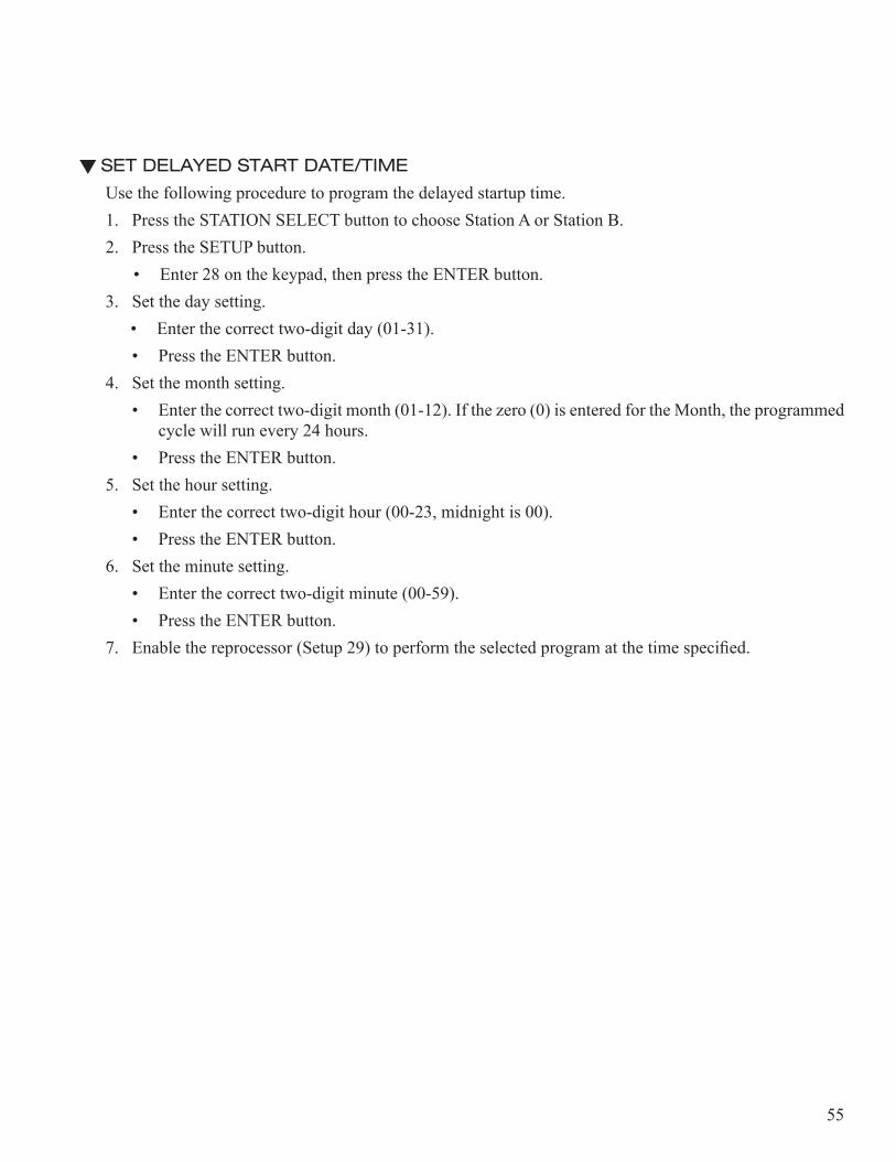
SET DELAYED START DATE/TIME
Use the following procedure to program the delayed startup time. 1. Press the STATION SELECT button to choose Station A or Station B.2. Press the SETUP button.
• Enter 28 on the keypad, then press the ENTER button.3. Set the day setting.
• Enter the correct two-digit day (01-31).• Press the ENTER button.
4. Set the month setting.• Enter the correct two-digit month (01-12). If the zero (0) is entered for the Month, the programmed
cycle will run every 24 hours.• Press the ENTER button.
5. Set the hour setting.• Enter the correct two-digit hour (00-23, midnight is 00).• Press the ENTER button.
6. Set the minute setting.• Enter the correct two-digit minute (00-59).• Press the ENTER button.
7. Enable the reprocessor (Setup 29) to perform the selected program at the time specified.
56
Station A
Flush
Disinfect
Rinse 2
Rinse 1
Alcohol
Air
A: Delayed Start
Day 01
WARN I N G
STATUS
Station A
Flush
Disinfect
Rinse 2
Rinse 1
Alcohol
Air
A: Delayed Start
Month 01
WARN I N G
STATUS
Station A
Flush
Disinfect
Rinse 2
Rinse 1
Alcohol
Air
A: Delayed Start
Set Hours 00:00
WARN I N G
STATUS
Station A
Flush
Disinfect
Rinse 2
Rinse 1
Alcohol
Air
A: Delayed Start
Set Minutes 00:00
WARN I N G
STATUS
Figure 28 Set Delayed Startup Screens
Disinfect
Station A Flush Disinfect Rinse 2
Rinse 1 Alcohol Air
A: Delayed Start
Day�� 01
WARN I N G
STATUS
Station B Rinse 1 Alcohol Air
Rinse 2 Flush
Disinfect
Station A Flush Disinfect Rinse 2
Rinse 1 Alcohol Air
A: Delayed Start
Month �� 01
WARN I N G
STATUS
Station B Rinse 1 Alcohol Air
Rinse 2 Flush
Disinfect
Station A Flush Disinfect Rinse 2
Rinse 1 Alcohol Air
A: Delayed Start
Set Hours�� 00:00
WARN I N G
STATUS
Station B Rinse 1 Alcohol Air
Rinse 2 Flush
Disinfect
Station A Flush Disinfect Rinse 2
Rinse 1 Alcohol Air
A: Delayed Start
Set Minutes� 00:00
WARN I N G
STATUS
Station B Rinse 1 Alcohol Air
Rinse 2 Flush
57
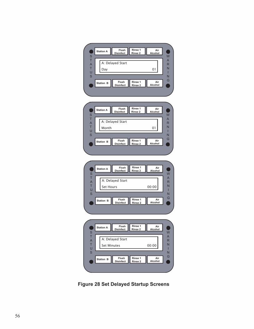
SET DELAYED START ENABLE
Use the following procedure to enable the delayed startup option.1. Press the STATION SELECT button to choose Station A or Station B.2. Press the SETUP button.
• Enter 29 on the keypad, then press the ENTER button. 3. Select the startup option.
• Press 1 on the keypad, then press the ENTER button to enable the delayed startup. • Press 0 on the keypad, then press the ENTER button to disable the delayed startup.
Station A
Flush
Disinfect
Rinse 2
Rinse 1
Alcohol
Air
A:
Start Enable 1
WARN I N G
STATUS
Figure 29 Enable Delayed Startup Screen
Disinfect
Station A Flush Disinfect Rinse 2
Rinse 1 Alcohol Air
A:
Start Enable�� 1
WARN I N G
STATUS
Station B Rinse 1 Alcohol Air
Rinse 2 Flush
58
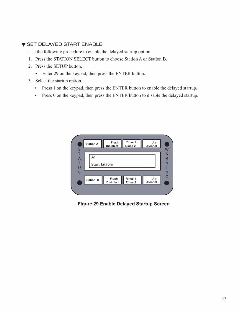
ENTER DIAGNOSTICS
Use the following procedure to enable the delayed startup option.1. Press the STATION SELECT button to choose Station A or Station B.2. Press the SETUP button.
Caution! Refer to the Service Manual for more informatio. Only properly trained personnel should attempt to perform the functions in the Diagnostics Menu.
Figure 30 Enter Diangostics Screen
59
CHAPTER 4
DIAGNOSTICS MENU
IntroductionUse the diagnostics functions to verify proper component operation when troubleshooting the reprocessor, to reset the reprocessor to default settings, to enable or disable sensors, to upgrade software, and to set up the reprocessor options.
PrecautionsAlways refer to the Safety section in the Introduction chapter before attempting to service the reprocessor. Verify a scope hook-up is connected in the basin and the floating lid in place before operating the reprocessor. Always activate Function 0 before exiting the Diagnostics Functions menu.
Note: Refer to the flow diagram for proper component identification when using the diagnostics functions for troubleshooting.
Note: Use the STATION SELECT button to select stations while in the Diagnostics Menu.
Warning! Endoscope reprocessing may be compromised while preforming Diagnostics functions during a disinfectant cycle.

60
Diagnostics FunctionsTo enter diagnostics functions:1. Press the SETUP button.2. Enter 88 on the keypad, then press the ENTER button.3. Enter the code: 135, then press the ENTER button.4. Press the STATION SELECT button to choose station A or station B5. Enter the function number on the keypad, then press the ENTER button.
Note: Before exiting the Diagnostics Menu, always choose Function 0 to deactivate all devices, then choose Function 14 on Station B to open the water valve.
Caution! Verify all sensors are enabled before exiting the Diagnostics Menu.
Station A Flush Disinfect Rinse 2
Rinse 1 Alcohol Air
Diagnositcs
WARN I N G
STATUS
61
FUNCTION 0–CLOSE ALL VALVES AND TURN ALL PUMPS OFFThis function closes all valves and turns all pumps OFF. This function also cancels Function 18. Always use Function 0 before exiting the Diagnostics Function menu.
Note: To select multiple components, activate Function 18, then choose the components.
Note: Before exiting the Diagnostics Menu, always choose Function 0 to deactivate all devices, then choose Function 14 on Station B to open the water valve.
FUNCTION 1–ACTIVATE DETERGENT VALVEThis function activates the detergent valve for the selected station.
FUNCTION 2– ACTIVATE WATER VALVEThis function activates the water valve on the main manifold for the selected station.
FUNCTION 3–ACTIVATE ALCOHOL PUMPThis function activates the alcohol pump for the selected station.
Caution! Do not activate the alcohol pump unless the alcohol valve is open. Perform Functions 18, 12, 3 to activate.
FUNCTION 4–ACTIVATE AIR SYSTEMThis function activates the air system (compressor and air valve) for the selected station.
Caution! Ensure the scope hook-up is connected in the basin before performing this procedure.
FUNCTION 5–ACTIVATE AIR VALVEThis function activates the air valve for the selected station.
FUNCTION 6–ACTIVATE CHAMBER VALVEThis function activates the chamber valve for the selected station.

62
FUNCTION 7–ACTIVATE DISINFECTANT PUMP
This function activates the disinfectant pump for the selected station.
Caution! Ensure the scope hook-up is connected in the basin before performing this procedure.
FUNCTION 8–ACTIVATE DISINFECTANT SUPPLY VALVEThis function activates the disinfectant supply valve for the selected station.
FUNCTION 9–ACTIVATE DISINFECTANT OVERFLOW VALVEThis function activates the disinfectant overflow valve for the selected station.
Note: To transfer fluid from the basin to the reservoir, activate Functions 1, 8, 9, 10.
FUNCTION 10–ACTIVATE DISINFECTANT RETURN VALVEThis function activates the disinfectant return valve for the selected station.
FUNCTION 11–ACTIVATE DRAIN VALVEThis function activates the drain valve for the selected station.
Note: To transfer fluid from the basin to the waste drain, activate Functions 18, 10, 11.
FUNCTION 12–ACTIVATE ALCOHOL VALVEThis function activates the alcohol valve for the selected station.
FUNCTION 13–ACTIVATE RECIRCULATION PUMPThis function activates the recirculation pump for the selected station (only on reprocessors with recirculation option).
FUNCTION 14–ACTIVATE WATER INLET VALVEThis function activates the water inlet valve for the entire reprocessor. This function is activated from station B diagnostics only.
Note: Before exiting the Diagnostics Menu, always choose Function 0 to deactivate all devices, then choose Function 14 on Station B to open the water valve.
63
FUNCTION 15–ACTIVATE DISINFECTANT INLET VALVEThis function activates the disinfectant inlet valve. The disinfectant inlet valve is used to supply the 0.2 micron filter during automatic water line disinfection procedures.
FUNCTION 16–ACTIVATE RECIRCULATION INLET VALVEThis function activates the recirculation inlet valve for the selected station. This function is only on reprocessors with a recirculation option.
FUNCTION 17–ACTIVATE RECIRCULATION CHAMBER VALVEThis function activates the recirculation chamber valve for the selected station. This function is only on reprocessors with a recirculation option.
FUNCTION 18–ACTIVATE VALVES INCREMENTALLYThis function allows multiple components to be activated at the same time. Function 0 cancels this function.
FUNCTION 19–ACTIVATE DETERGENT PUMPThis function activates the detergent pump for the selected station.
Caution! Do not activate the detergent pump unless the detergent valve is open. Perform Functions 18, 1, 19 to activate.
64
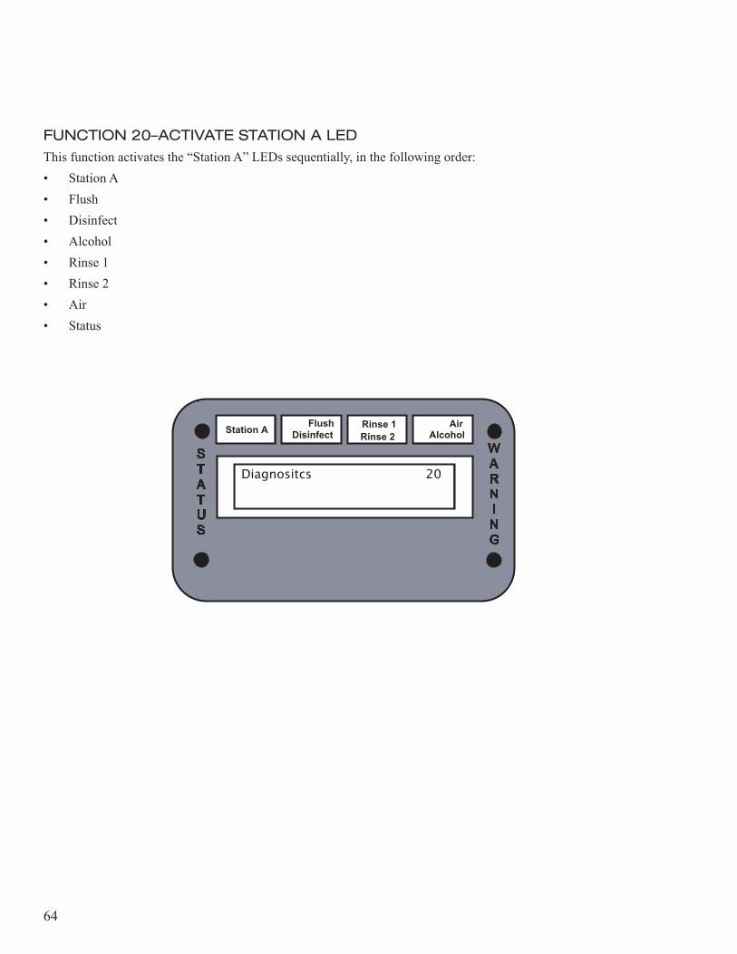
FUNCTION 20–ACTIVATE STATION A LEDThis function activates the “Station A” LEDs sequentially, in the following order:• Station A• Flush• Disinfect• Alcohol• Rinse 1• Rinse 2• Air• Status
Station A Flush Disinfect Rinse 2
Rinse 1 Alcohol Air
Diagnositcs� 20
WARN I N G
STATUS
65
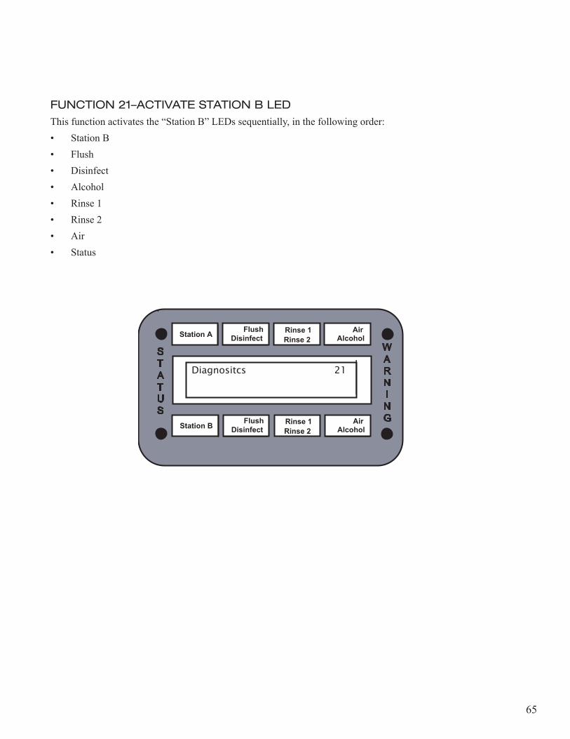
FUNCTION 21–ACTIVATE STATION B LEDThis function activates the “Station B” LEDs sequentially, in the following order:• Station B• Flush• Disinfect• Alcohol• Rinse 1• Rinse 2• Air• Status
Station A Flush Disinfect Rinse 2
Rinse 1 Alcohol Air
Diagnositcs� 21
WARN I N G
STATUS
Station B Flush Disinfect Rinse 2
Rinse 1 Alcohol Air
66
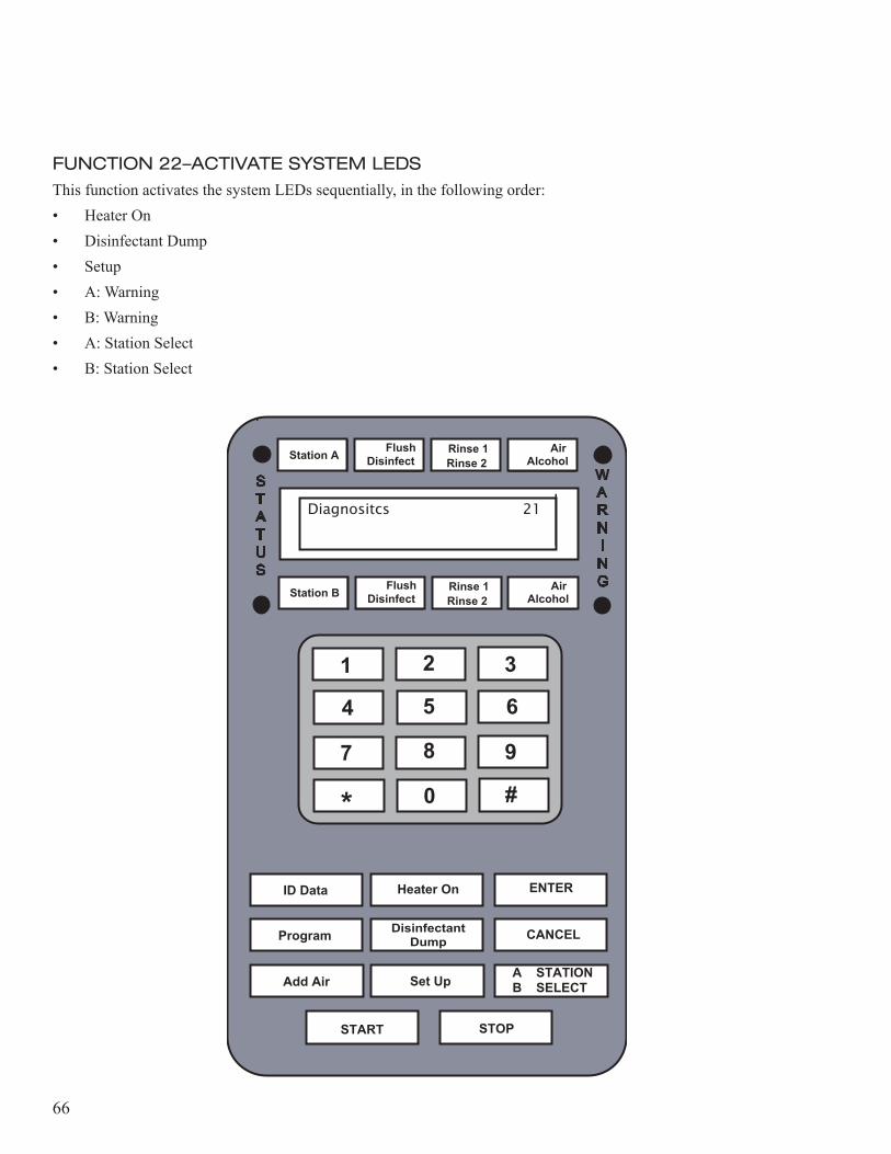
FUNCTION 22–ACTIVATE SYSTEM LEDSThis function activates the system LEDs sequentially, in the following order:• Heater On• Disinfectant Dump• Setup• A: Warning• B: Warning• A: Station Select• B: Station Select
Station A Flush Disinfect Rinse 2
Rinse 1 Alcohol Air
Diagnositcs� 21
WARN I N G
STATUS
Station B Flush Disinfect Rinse 2
Rinse 1 Alcohol Air
1 2
5
3
7 8 9
4 6
* 0 #
START
ID Data
Program
Heater On ENTER
Add Air Set Up A STATIONB SELECT
DisinfectantDump CANCEL
STOP
67
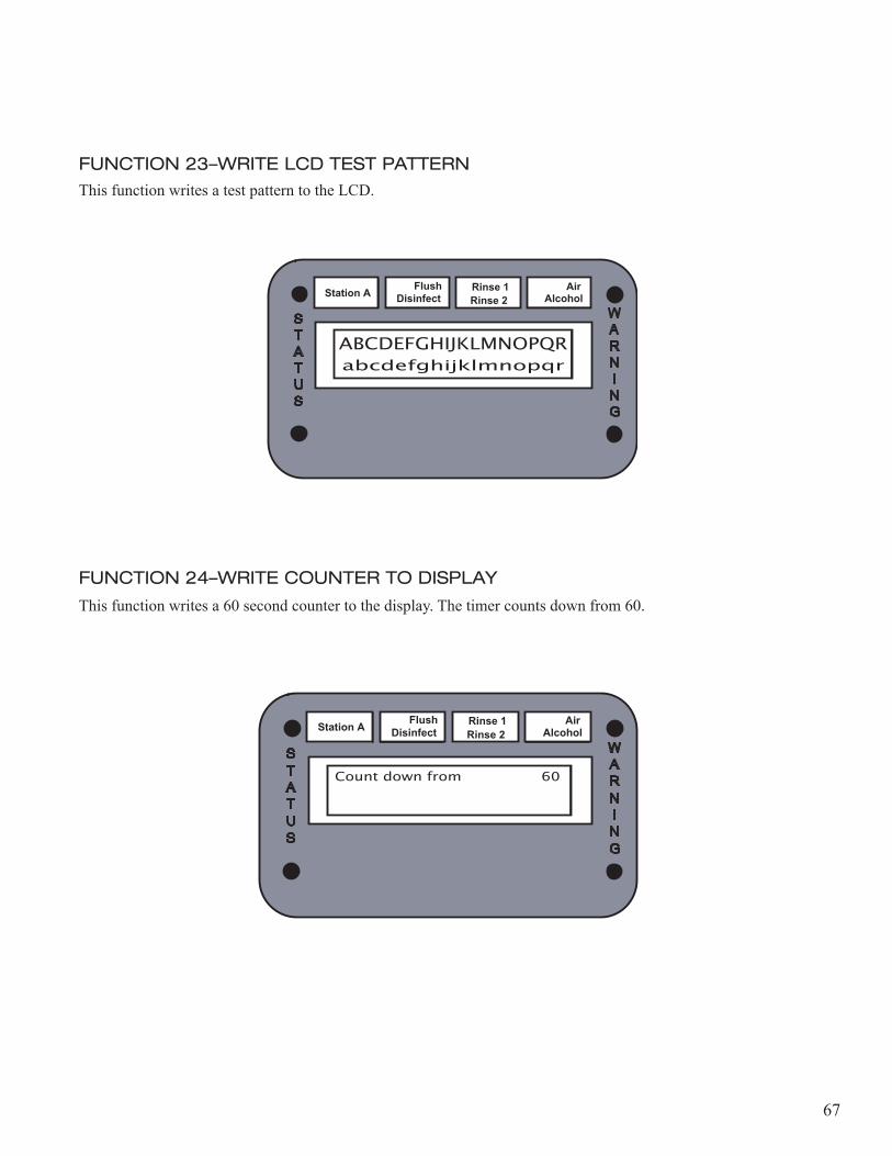
FUNCTION 23–WRITE LCD TEST PATTERNThis function writes a test pattern to the LCD.
FUNCTION 24–WRITE COUNTER TO DISPLAY
This function writes a 60 second counter to the display. The timer counts down from 60.
Station A Flush Disinfect Rinse 2
Rinse 1 Alcohol Air
ABCDEFGHIJKLMNOPQR
WARN I N G
STATUS
abcdefghijklmnopqr
Station A Flush Disinfect Rinse 2
Rinse 1 Alcohol Air
Count down from 60 WARN I N G
STATUS
68
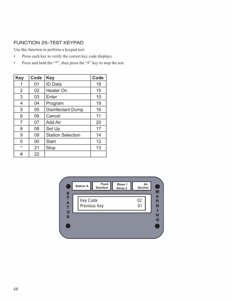
FUNCTION 25–TEST KEYPADUse this function to perform a keypad test.• Press each key to verify the correct key code displays.• Press and hold the “*”, then press the “#” key to stop the test
Key Code Key Code1 01 ID Data 182 02 Heater On 153 03 Enter 104 04 Program 195 05 Disinfectant Dump 166 06 Cancel 117 07 Add Air 208 08 Set Up 179 09 Station Selection 140 00 Start 12* 21 Stop 13# 22
Station A Flush Disinfect Rinse 2
Rinse 1 Alcohol Air
Key Code 02Previous Key� 01
WARN I N G
STATUS
69
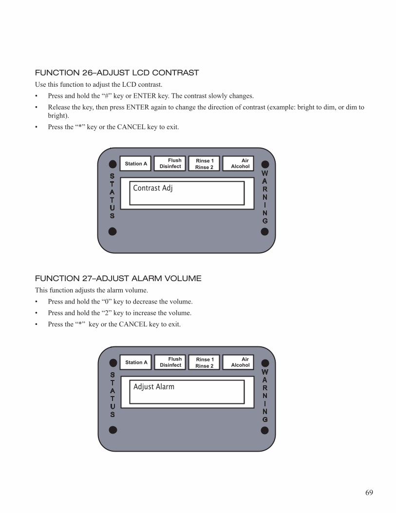
FUNCTION 26–ADJUST LCD CONTRASTUse this function to adjust the LCD contrast.• Press and hold the “#” key or ENTER key. The contrast slowly changes.• Release the key, then press ENTER again to change the direction of contrast (example: bright to dim, or dim to
bright).• Press the “*” key or the CANCEL key to exit.
FUNCTION 27–ADJUST ALARM VOLUMEThis function adjusts the alarm volume.• Press and hold the “0” key to decrease the volume.• Press and hold the “2” key to increase the volume.• Press the “*” key or the CANCEL key to exit.
Station A Flush Disinfect Rinse 2
Rinse 1 Alcohol Air
Contrast Adj
WARN I N G
STATUS
Station A Flush Disinfect Rinse 2
Rinse 1 Alcohol Air
Adjust Alarm
WARN I N G
STATUS
70
FUNCTION 28–LOCK COVER (OPTIONAL)
This function activates the lidlock for the selected station.
FUNCTION 29–UNLOCK COVER (OPTIONAL)This function deactivates the lidlock for the selected station.
Station A Flush Disinfect Rinse 2
Rinse 1 Alcohol Air
Diagnositcs
WARN I N G
STATUS
Station A Flush Disinfect Rinse 2
Rinse 1 Alcohol Air
Diagnositcs
WARN I N G
STATUS
71
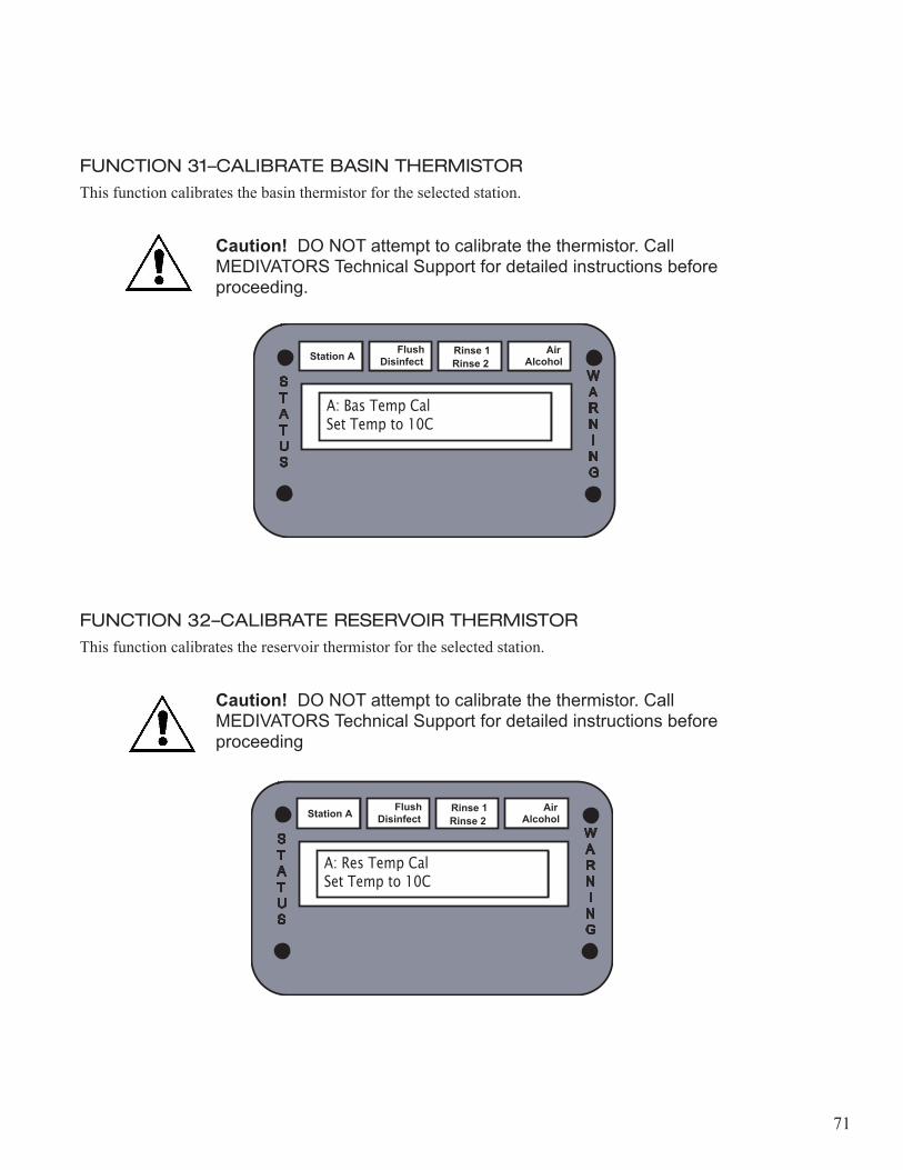
FUNCTION 31–CALIBRATE BASIN THERMISTORThis function calibrates the basin thermistor for the selected station.
Caution! DO NOT attempt to calibrate the thermistor. Call MEDIVATORS Technical Support for detailed instructions before proceeding.
FUNCTION 32–CALIBRATE RESERVOIR THERMISTORThis function calibrates the reservoir thermistor for the selected station.
Caution! DO NOT attempt to calibrate the thermistor. Call MEDIVATORS Technical Support for detailed instructions before proceeding
Station A Flush Disinfect Rinse 2
Rinse 1 Alcohol Air
A: Bas Temp CalSet Temp to 10C
WARN I N G
STATUS
Station A Flush Disinfect Rinse 2
Rinse 1 Alcohol Air
A: Res Temp CalSet Temp to 10C
WARN I N G
STATUS
72
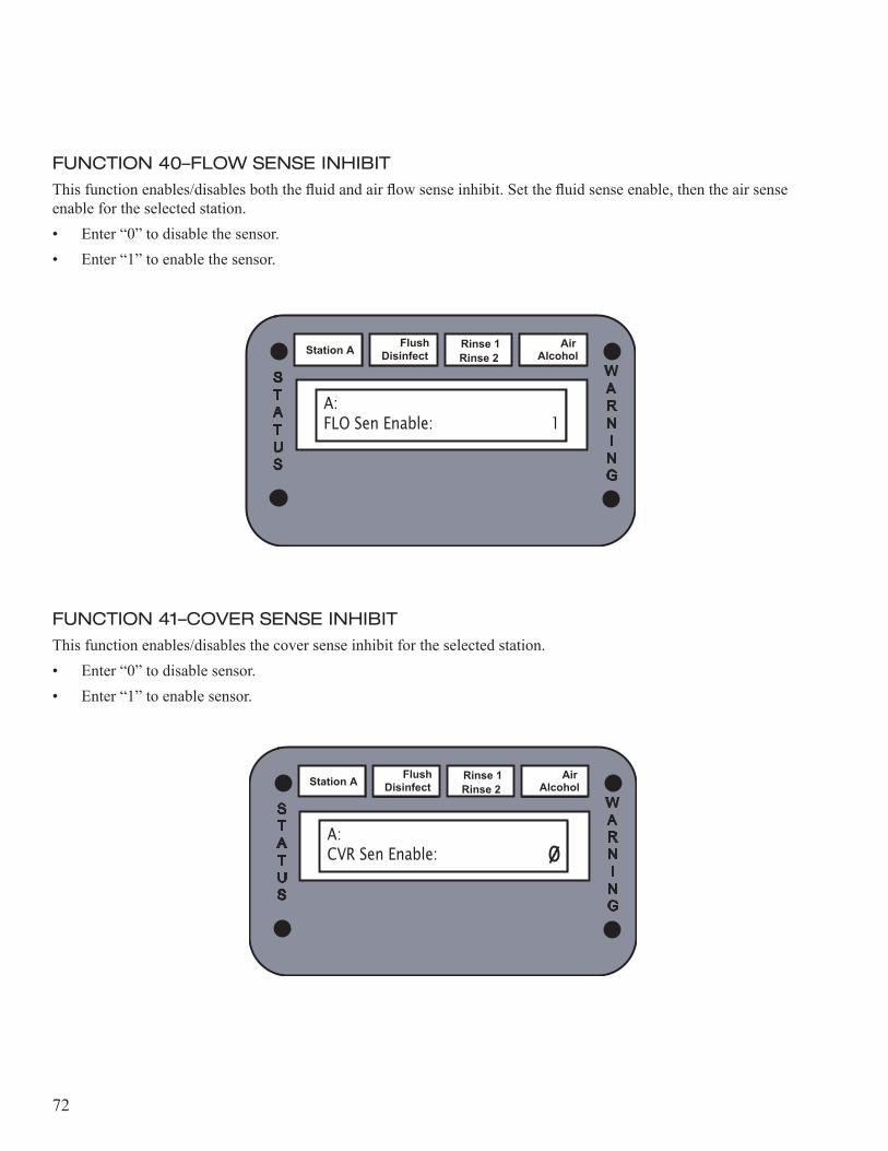
FUNCTION 40–FLOW SENSE INHIBITThis function enables/disables both the fluid and air flow sense inhibit. Set the fluid sense enable, then the air sense enable for the selected station.• Enter “0” to disable the sensor.• Enter “1” to enable the sensor.
FUNCTION 41–COVER SENSE INHIBITThis function enables/disables the cover sense inhibit for the selected station.• Enter “0” to disable sensor.• Enter “1” to enable sensor.
Station A Flush Disinfect Rinse 2
Rinse 1 Alcohol Air
A: FLO Sen Enable:�� 1
WARN I N G
STATUS
Station A Flush Disinfect Rinse 2
Rinse 1 Alcohol Air
A: CVR Sen Enable:��
WARN I N G
STATUS
73
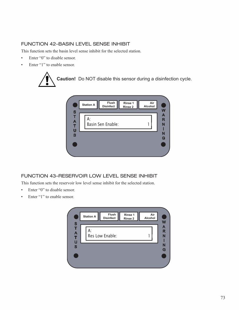
FUNCTION 42–BASIN LEVEL SENSE INHIBITThis function sets the basin level sense inhibit for the selected station.• Enter “0” to disable sensor.• Enter “1” to enable sensor.
Caution! Do NOT disable this sensor during a disinfection cycle.
FUNCTION 43–RESERVOIR LOW LEVEL SENSE INHIBITThis function sets the reservoir low level sense inhibit for the selected station.• Enter “0” to disable sensor.• Enter “1” to enable sensor.
Station A Flush Disinfect Rinse 2
Rinse 1 Alcohol Air
A: Basin Sen Enable:�� 1��
WARN I N G
STATUS
Station A Flush Disinfect Rinse 2
Rinse 1 Alcohol Air
A: Res Low Enable:�� 1��
WARN I N G
STATUS
74
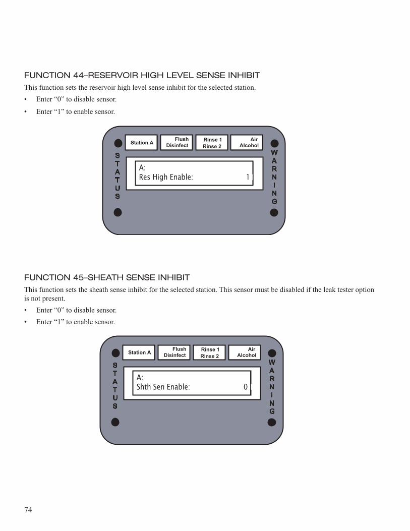
FUNCTION 44–RESERVOIR HIGH LEVEL SENSE INHIBITThis function sets the reservoir high level sense inhibit for the selected station.• Enter “0” to disable sensor.
• Enter “1” to enable sensor.
FUNCTION 45–SHEATH SENSE INHIBITThis function sets the sheath sense inhibit for the selected station. This sensor must be disabled if the leak tester option is not present.• Enter “0” to disable sensor.• Enter “1” to enable sensor.
Station A Flush Disinfect Rinse 2
Rinse 1 Alcohol Air
A: Res High Enable:�� 1��
WARN I N G
STATUS
Station A Flush Disinfect Rinse 2
Rinse 1 Alcohol Air
A: Shth Sen Enable:�� 0��
WARN I N G
STATUS
75
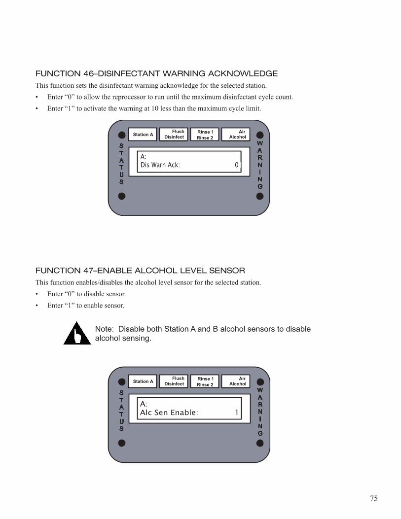
FUNCTION 46–DISINFECTANT WARNING ACKNOWLEDGEThis function sets the disinfectant warning acknowledge for the selected station.• Enter “0” to allow the reprocessor to run until the maximum disinfectant cycle count.• Enter “1” to activate the warning at 10 less than the maximum cycle limit.
FUNCTION 47–ENABLE ALCOHOL LEVEL SENSORThis function enables/disables the alcohol level sensor for the selected station.• Enter “0” to disable sensor.• Enter “1” to enable sensor.
Note: Disable both Station A and B alcohol sensors to disable alcohol sensing.
Station A Flush Disinfect Rinse 2
Rinse 1 Alcohol Air
A: Dis Warn Ack:�� 0��
WARN I N G
STATUS
Station A Flush Disinfect Rinse 2
Rinse 1 Alcohol Air
A:Alc Sen Enable:�� 1
WARN I N G
STATUS
76
FUNCTION 48–ENABLE DETERGENT SENSORThis function enables/disables the detergent sensor for the selected station.• Enter “0” to disable sensor.• Enter “1” to enable sensor.
Note: Disable both Station A and B detergent sensors to disable detergent sensing.
Station A Flush Disinfect Rinse 2
Rinse 1 Alcohol Air
A:Det Sen Enable:�� 1
WARN I N G
STATUS
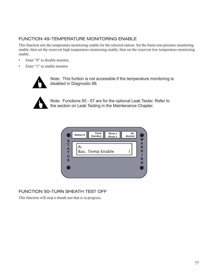
77
FUNCTION 49–TEMPERATURE MONITORING ENABLEThis function sets the temperature monitoring enable for the selected station. Set the basin tem-perature monitoring enable, then set the reservoir high temperature monitoring enable, then set the reservoir low temperature monitoring enable.• Enter “0” to disable monitor.• Enter “1” to enable monitor.
Note: This funtion is not accessible if the temperature monitoring is disabled in Diagnostic 88.
Note: Functions 50 - 57 are for the optional Leak Tester. Refer to the section on Leak Testing in the Maintenance Chapter.
FUNCTION 50–TURN SHEATH TEST OFFThis function will stop a sheath test that is in progress.
Station A Flush Disinfect Rinse 2
Rinse 1 Alcohol Air
A:Bas. Temp Enable � 1
WARN I N G
STATUS
78
FUNCTION 51–ACTIVATE SHEATH VALVEThis function activates the sheath valve.
FUNCTION 52–ACTIVATE SHEATH TEST COMPRESSOR VALVE
This function activates the sheath test compressor valve.
Station A Flush Disinfect Rinse 2
Rinse 1 Alcohol Air
Diagnositcs
WARN I N G
STATUS
Station A Flush Disinfect Rinse 2
Rinse 1 Alcohol Air
Diagnositcs
WARN I N G
STATUS
79
FUNCTION 53–ACTIVATE SHEATH TEST COMPRESSOR
This functions activates the sheath test compressor.
FUNCTION 54–TURN OFF ALL VALVES AND RESET LATCHESThis function turns off all valves, turns off the compressor, and resets the latches for the sheath tester.
Station A Flush Disinfect Rinse 2
Rinse 1 Alcohol Air
Diagnositcs
WARN I N G
STATUS
Station A Flush Disinfect Rinse 2
Rinse 1 Alcohol Air
Diagnositcs
WARN I N G
STATUS
80
FUNCTION 55–TURN OFF SHEATH TEST COMPRESSORThis function turns off the sheath test compressor.
FUNCTION 56–ACTIVATE SHEATH TEST
This function activates the sheath test.
Station A Flush Disinfect Rinse 2
Rinse 1 Alcohol Air
Diagnositcs
WARN I N G
STATUS
Station A Flush Disinfect Rinse 2
Rinse 1 Alcohol Air
Diagnositcs
WARN I N G
STATUS
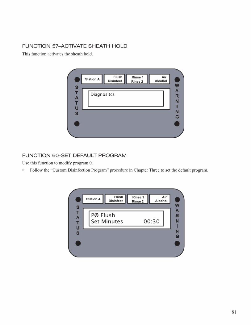
81
FUNCTION 57–ACTIVATE SHEATH HOLD
This function activates the sheath hold.
FUNCTION 60–SET DEFAULT PROGRAMUse this function to modify program 0.• Follow the “Custom Disinfection Program” procedure in Chapter Three to set the default program.
Station A Flush Disinfect Rinse 2
Rinse 1 Alcohol Air
Diagnositcs
WARN I N G
STATUS
Station A Flush Disinfect Rinse 2
Rinse 1 Alcohol Air
PO FlushSet Minutes� 00:30
WARN I N G
STATUS
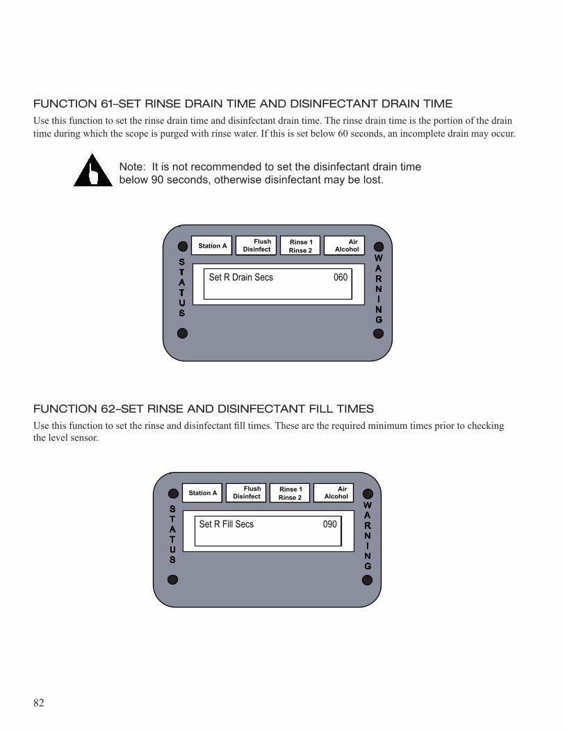
82
FUNCTION 61–SET RINSE DRAIN TIME AND DISINFECTANT DRAIN TIMEUse this function to set the rinse drain time and disinfectant drain time. The rinse drain time is the portion of the drain time during which the scope is purged with rinse water. If this is set below 60 seconds, an incomplete drain may occur.
Note: It is not recommended to set the disinfectant drain time below 90 seconds, otherwise disinfectant may be lost.
FUNCTION 62–SET RINSE AND DISINFECTANT FILL TIMESUse this function to set the rinse and disinfectant fill times. These are the required minimum times prior to checking the level sensor.
Station A Flush Disinfect Rinse 2
Rinse 1 Alcohol Air
Set R Drain Secs 060
WARN I N G
STATUS
Station A Flush Disinfect Rinse 2
Rinse 1 Alcohol Air
Set R Fill Secs 090
WARN I N G
STATUS
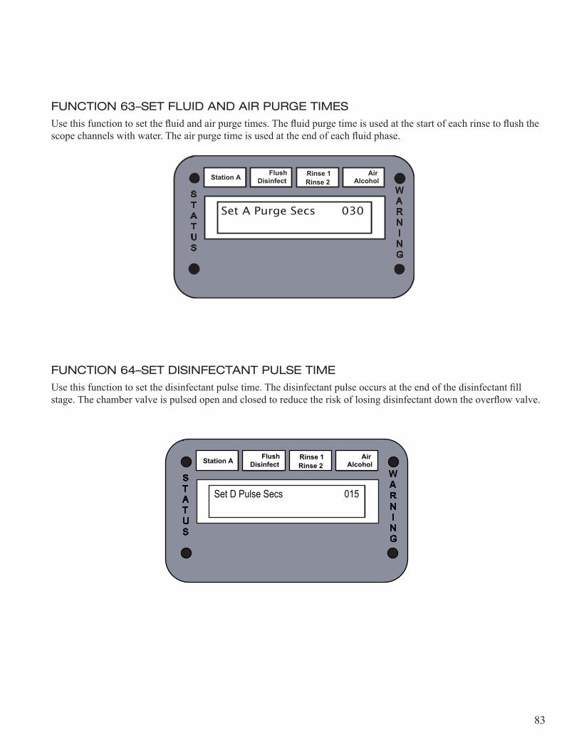
83
FUNCTION 63–SET FLUID AND AIR PURGE TIMESUse this function to set the fluid and air purge times. The fluid purge time is used at the start of each rinse to flush the scope channels with water. The air purge time is used at the end of each fluid phase.
FUNCTION 64–SET DISINFECTANT PULSE TIMEUse this function to set the disinfectant pulse time. The disinfectant pulse occurs at the end of the disinfectant fill stage. The chamber valve is pulsed open and closed to reduce the risk of losing disinfectant down the overflow valve.
Station A Flush Disinfect Rinse 2
Rinse 1 Alcohol Air
Set A Purge Secs 030
WARN I N G
STATUS
Station A Flush Disinfect Rinse 2
Rinse 1 Alcohol Air
Set D Pulse Secs 015
WARN I N G
STATUS
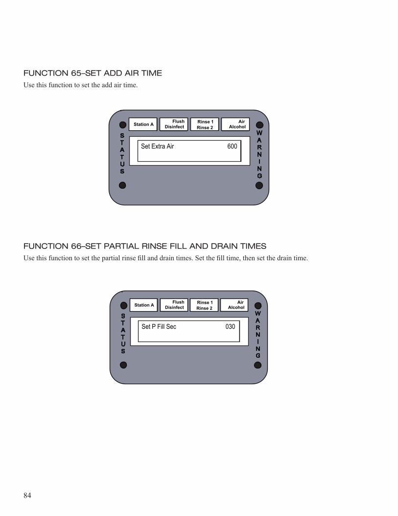
84
FUNCTION 65–SET ADD AIR TIMEUse this function to set the add air time.
FUNCTION 66–SET PARTIAL RINSE FILL AND DRAIN TIMESUse this function to set the partial rinse fill and drain times. Set the fill time, then set the drain time.
Station A Flush Disinfect Rinse 2
Rinse 1 Alcohol Air
Set Extra Air 600
WARN I N G
STATUS
Station A Flush Disinfect Rinse 2
Rinse 1 Alcohol Air
Set P Fill Sec 030
WARN I N G
STATUS
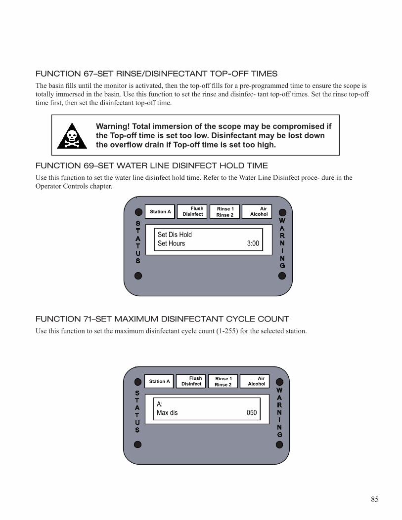
85
FUNCTION 67–SET RINSE/DISINFECTANT TOP-OFF TIMESThe basin fills until the monitor is activated, then the top-off fills for a pre-programmed time to ensure the scope is totally immersed in the basin. Use this function to set the rinse and disinfec- tant top-off times. Set the rinse top-off time first, then set the disinfectant top-off time.
Warning! Total immersion of the scope may be compromised if the Top-off time is set too low. Disinfectant may be lost down the overflow drain if Top-off time is set too high.
FUNCTION 69–SET WATER LINE DISINFECT HOLD TIMEUse this function to set the water line disinfect hold time. Refer to the Water Line Disinfect proce- dure in the Operator Controls chapter.
FUNCTION 71–SET MAXIMUM DISINFECTANT CYCLE COUNTUse this function to set the maximum disinfectant cycle count (1-255) for the selected station.
Station A Flush Disinfect Rinse 2
Rinse 1 Alcohol Air
Set Dis HoldSet Hours 3:00
WARN I N G
STATUS
Station A Flush Disinfect Rinse 2
Rinse 1 Alcohol Air
A:Max dis 050
WARN I N G
STATUS
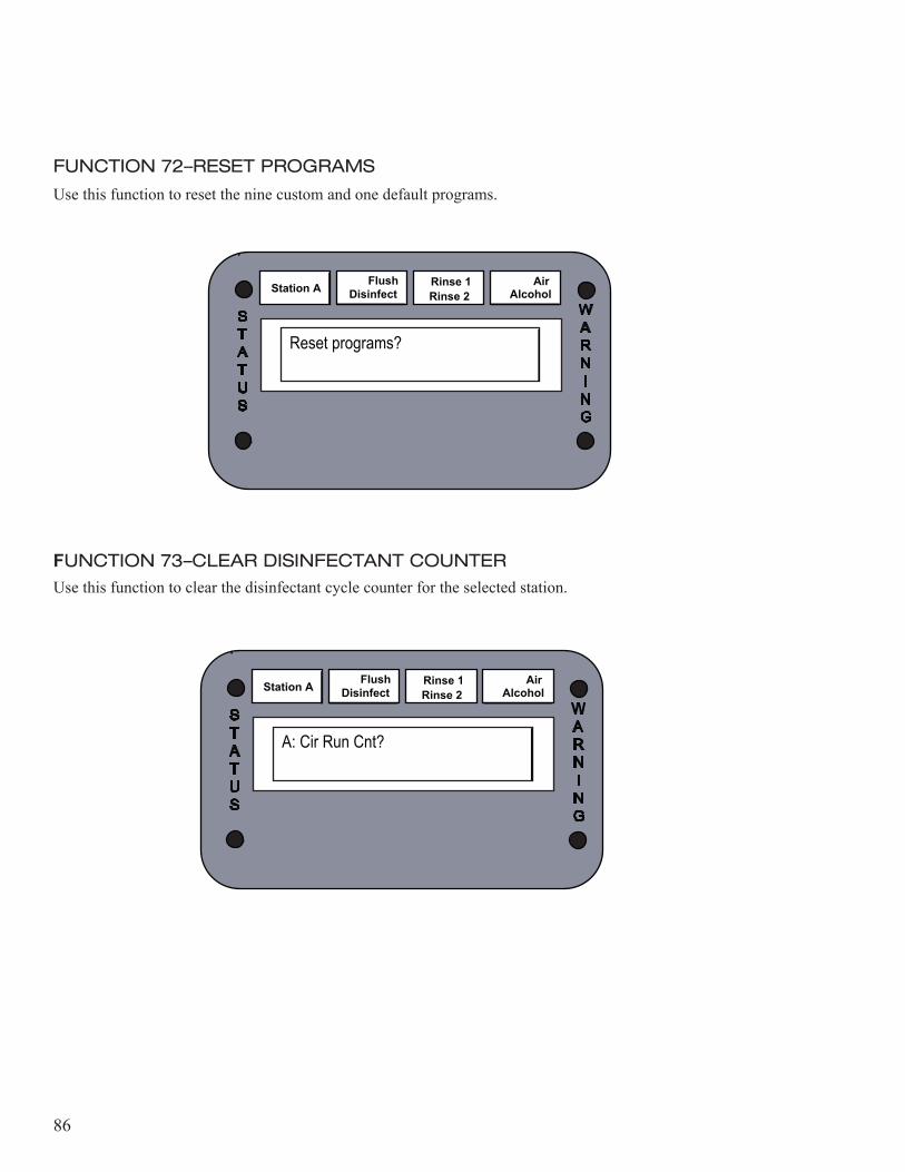
86
FUNCTION 72–RESET PROGRAMS
Use this function to reset the nine custom and one default programs.
FUNCTION 73–CLEAR DISINFECTANT COUNTERUse this function to clear the disinfectant cycle counter for the selected station.
Station A Flush Disinfect Rinse 2
Rinse 1 Alcohol Air
Reset programs?
WARN I N G
STATUS
Station A Flush Disinfect Rinse 2
Rinse 1 Alcohol Air
A: Cir Run Cnt?
WARN I N G
STATUS

87
FUNCTION 74–SET MAXIMUM RESERVOIR TEMPERATUREUse this function to set the maximum reservoir temperature for the selected station. The tempera- tures are displayed in Celsius.
FUNCTION 75–SET MINIMUM BASIN TEMPERATUREUse this function to set the minimum basin temperature for the selected station. The temperatures are displayed in Celsius.
Station A Flush Disinfect Rinse 2
Rinse 1 Alcohol Air
A: Max Res Temp 45
WARN I N G
STATUS
Station A Flush Disinfect Rinse 2
Rinse 1 Alcohol Air
A: Min Bas Temp 10
WARN I N G
STATUS
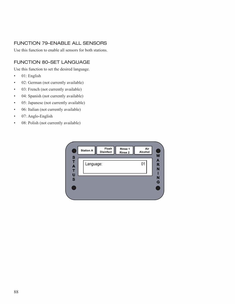
88
FUNCTION 79–ENABLE ALL SENSORSUse this function to enable all sensors for both stations.
FUNCTION 80–SET LANGUAGEUse this function to set the desired language.• 01: English• 02: German (not currently available)• 03: French (not currently available)• 04: Spanish (not currently available)• 05: Japanese (not currently available)• 06: Italian (not currently available)• 07: Anglo-English• 08: Polish (not currently available)
Station A Flush Disinfect Rinse 2
Rinse 1 Alcohol Air
Language: 01
WARN I N G
STATUS
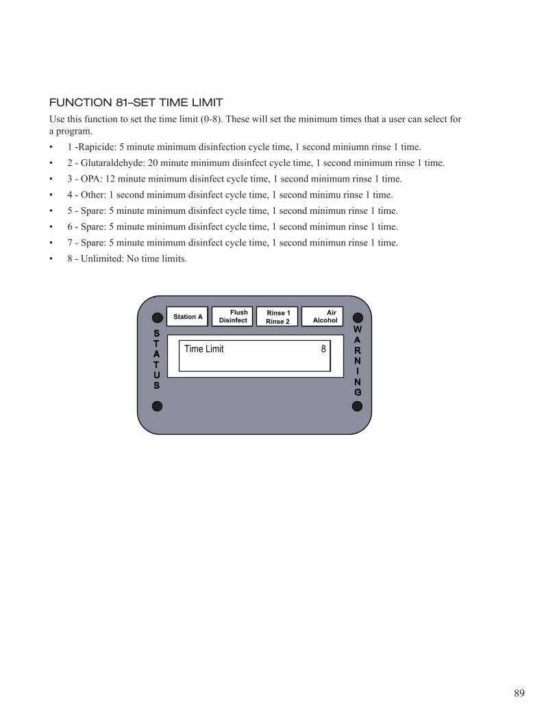
89
FUNCTION 81–SET TIME LIMITUse this function to set the time limit (0-8). These will set the minimum times that a user can select for a program.• 1 -Rapicide: 5 minute minimum disinfection cycle time, 1 second miniumn rinse 1 time.• 2 - Glutaraldehyde: 20 minute minimum disinfect cycle time, 1 second minimum rinse 1 time.• 3 - OPA: 12 minute minimum disinfect cycle time, 1 second minimum rinse 1 time.• 4 - Other: 1 second minimum disinfect cycle time, 1 second minimu rinse 1 time.• 5 - Spare: 5 minute minimum disinfect cycle time, 1 second minimun rinse 1 time.• 6 - Spare: 5 minute minimum disinfect cycle time, 1 second minimun rinse 1 time.• 7 - Spare: 5 minute minimum disinfect cycle time, 1 second minimun rinse 1 time.• 8 - Unlimited: No time limits.
Station A Flush Disinfect Rinse 2
Rinse 1 Alcohol Air
Time Limit 8
WARN I N G
STATUS
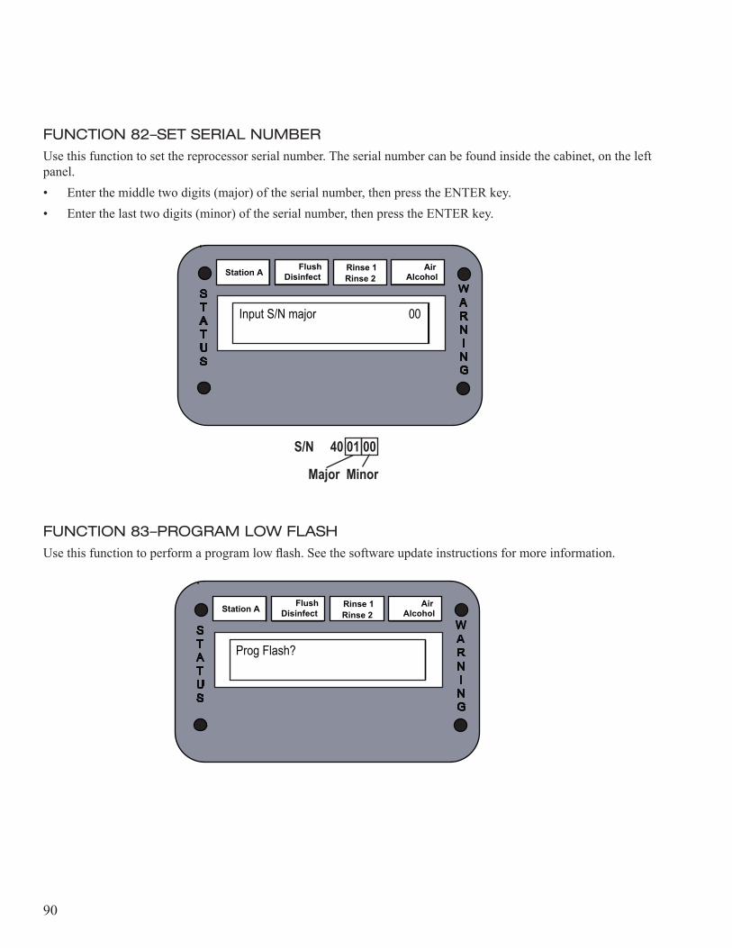
90
FUNCTION 82–SET SERIAL NUMBERUse this function to set the reprocessor serial number. The serial number can be found inside the cabinet, on the left panel.• Enter the middle two digits (major) of the serial number, then press the ENTER key.• Enter the last two digits (minor) of the serial number, then press the ENTER key.
FUNCTION 83–PROGRAM LOW FLASHUse this function to perform a program low flash. See the software update instructions for more information.
Station A Flush Disinfect Rinse 2
Rinse 1 Alcohol Air
Input S/N major 00
WARN I N G
STATUS
Station A Flush Disinfect Rinse 2
Rinse 1 Alcohol Air
Prog Flash?
WARN I N G
STATUS
S/N 40 01 00
Major Minor
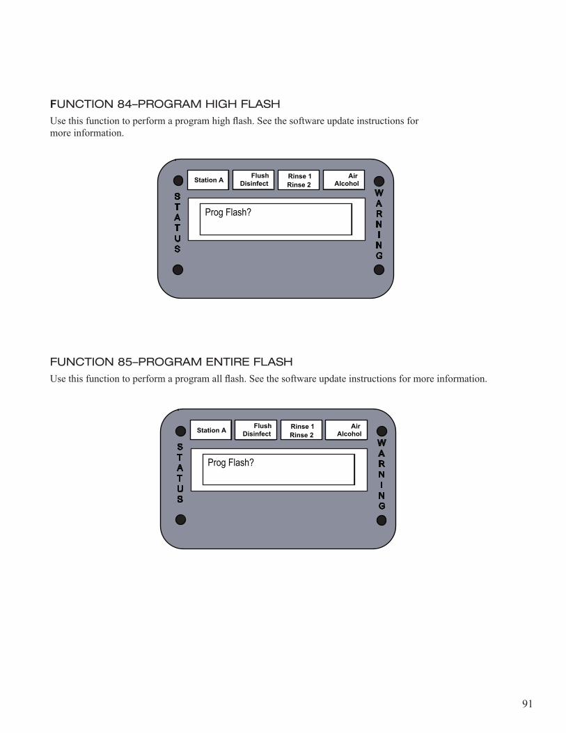
91
FUNCTION 84–PROGRAM HIGH FLASHUse this function to perform a program high flash. See the software update instructions for more information.
FUNCTION 85–PROGRAM ENTIRE FLASHUse this function to perform a program all flash. See the software update instructions for more information.
Station A Flush Disinfect Rinse 2
Rinse 1 Alcohol Air
Prog Flash?
WARN I N G
STATUS
Station A Flush Disinfect Rinse 2
Rinse 1 Alcohol Air
Prog Flash?
WARN I N G
STATUS

92
FUNCTION 86–INITIALIZE NVRAMUse this function to initialize the NVRAM
Caution! Initializing the NVRAM will set all sensors and programs to default. Be sure to record all custom settings and programs before performing this function.
FUNCTION 87–DISABLE ALL SENSORSUse this function to disable all sensors.
FUNCTION 88–SET OPTIONSUse this function to set the options. Options include recirculation, water line disinfect, heated reservoirs, and temperature sensing for the selected station.• Enter “0” if the reprocessor does not have this option.• Enter “1” if the reprocessor has this option.
Station A Flush Disinfect Rinse 2
Rinse 1 Alcohol Air
A: Recirc optionO
WARN I N G
STATUS
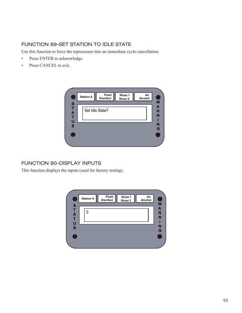
93
FUNCTION 89-SET STATION TO IDLE STATEUse this function to force the reprocessor into an immediate cycle cancellation.• Press ENTER to acknowledge.• Press CANCEL to exit.
FUNCTION 90–DISPLAY INPUTSThis function displays the inputs (used for factory testing).
Station A Flush Disinfect Rinse 2
Rinse 1 Alcohol Air
Set Idle State?
WARN I N G
STATUS
Station A Flush Disinfect Rinse 2
Rinse 1 Alcohol Air
0
WARN I N G
STATUS
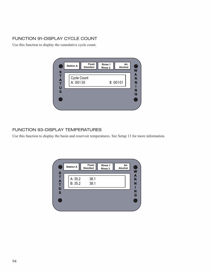
94
FUNCTION 91-DISPLAY CYCLE COUNTUse this function to display the cumulative cycle count.
FUNCTION 93–DISPLAY TEMPERATURESUse this function to display the basin and reservoir temperatures. See Setup 13 for more information.
Station A Flush Disinfect Rinse 2
Rinse 1 Alcohol Air
Cycle CountA: 00130 B: 00101
WARN I N G
STATUS
Station A Flush Disinfect Rinse 2
Rinse 1 Alcohol Air
A: 35.2 38.1B: 35.2 38.1
WARN I N G
STATUS
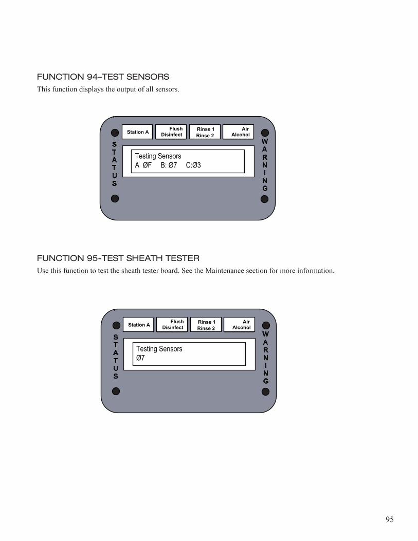
95
FUNCTION 94–TEST SENSORSThis function displays the output of all sensors.
FUNCTION 95-TEST SHEATH TESTERUse this function to test the sheath tester board. See the Maintenance section for more information.
Station A Flush Disinfect Rinse 2
Rinse 1 Alcohol Air
Testing SensorsA ØF B: Ø7 C:Ø3
WARN I N G
STATUS
Station A Flush Disinfect Rinse 2
Rinse 1 Alcohol Air
Testing SensorsØ7
WARN I N G
STATUS

96
97
Chapter 5
OPERATION
IntroductionThis chapter explains how to startup and shut down the reprocessor, how to program the reprocessor for a delayed start sequence, how to leak test endoscopes and how to prepare and disinfect an endoscope.
98
Cycle OperationStartup PhaseDuring start-up phase, the software monitors certain sensors. If any of the monitored sensors are not satisfied during start-up, an error message is displayed and the process is halted. To cancel the start-up phase, press the STOP key. To resume, resolve the error according to the error message displayed, press the STOP key, and then press the Start key. Please refer to the maintenance and troubleshooting section for appropriate instructions to resolve error messages. If the leak tester option is installed and enabled, a 40 second sheath test is activated during the start-up phase. During that test the scope is pressurized to 160mmhg for 20 seconds then the pressure is monitored for the remaining 20 seconds. If the pressure drops below 50mmhg, a “Sheath Fail” error message is displayed and the process is halted. To cancel the start-up phase, press the STOP key. To resume, resolve the issue according to the error message displayed, press the STOP key, and then press the Start key.
Wash PhaseThe wash phase consists of either a Soak segment or a Flush segment. The operator has the choice to run either one of the segments or neither, but never both during the same cycle program. Setting the Soak time above zero using Setup 5, disables the second segment. To run the Flush segment during a programmed cycle the operator must set the Soak time to zero and the Flush to the desired time. During Soak, the detergent is injected into the basin according to the programmed detergent injection time. The default detergent injection time is 3 seconds (~9ml). Please refer to the table in the Programming the Reprocessor section for the appropriate dilution and timing settings. After injection, water fills the basin. If the re-circulation option is included and enabled, the basin fluid is then flushed through the scope channels. Otherwise the scope is soaked in the basin for the programmed soak time. The basin is then drained while the scope channels are flushed with fresh water. A Rinse Soak period then follows which is identical to the soak period. However, no detergent is injected during this time.During flush, the scope channels are injected with detergent for the programmed injection time and then flushed with water for the desired flush time. During this segment all of the fluid exiting the scope is flushed down the drain.

99
Disinfectant PhaseDuring the disinfectant phase, scope channels are purged with disinfectant. Subsequently, the basin is filled with disinfectant through the chamber valve. Once the basin is filled and the temperature is stabilized inside the basin, the scope is soaked for the desired disinfectant soak time. During the soak period, if the re-circulation option is included and enabled, the scope channels are purged via the re-circ pump. Otherwise the disinfectant is pumped through the channels and returned to the reservoir through the overflow valve. After soak, the disinfectant is returned to the reservoir by gravity. The temperature stabilization process only applies for reprocessors with an installed and enabled heat option.
Rinse 1 PhaseDuring Rinse 1, the basin is partially filled with water and then drained to eliminate the foam residue from inside the scope and from the basin. Then, the basin is filled with fresh water while the scope channels are flushed. Once the basin fills up, fluid is purged through the scope channels if the re-circulation option is included. Otherwise the scope channels are flushed with fresh water. The basin is then drained while the channels are purged with fresh water.
Rinse 2 PhaseRinse 2 phase is identical to rinse 1 phase excluding the partial rinse period.
Rinse 3 PhaseRinse 3 phase is identical to rinse 2 phase.
Alcohol PhaseDuring the alcohol phase, alcohol is injected through scope channels then followed by an air purge for the Alcohol time programmed in Setup 5. The alcohol injection time is also programmed using Setup 5.
100
Air PhaseThe air phase is simply a programmed time during which air is purged through the scope channels.
Note: Please refer to the Disinfection Cycle Chart for user programmable time settings, default state times, and time limitations.
Note: Every drain transaction is followed by an air purge where air is flushed through the scope channels and internal fluid lines. The Air LED on the control panel blinks during air purge.
Note: During each phase of the cycle, an LED illuminates to indicate the present phase. The Flush LED indicates that one of the wash phase segments is running.
101
Pre-start InspectionUse the following procedure to inspect the reprocessor before startup.1. Check the external pre-filters on the incoming water supply. Replace any filters if the pressure drop
across any filter is greater than 10 psi. Inspect the pressure gauges for pressure reading when water is flowing through the filters.
2. Check the disinfectant filter record. Replace the filter at every disinfectant change, or more often during high usage.
3. Check the detergent reservoir (if utilized) for proper detergent level. Add detergent, if necessary.4. Check the alcohol reservoir (if utilized) for proper alcohol level. Add alcohol, if necessary.
Note: Allow 1 inch of space at the top of the detergent and alcohol reservoir to accommodate the reservoir sensors.
5. Check the disinfectant reuse life expiration date for the reservoir. Replace expired disinfectant.6. Test the disinfectant in the reservoir for potency. Replace any disinfectant that has less than acceptable
potency levels.
Warning! Never use disinfectant beyond the manufacturer’s recommended reuse life, even if the potency levels are acceptable.
Warning! Never use disinfectant with unacceptable potency levels, even if the reuse date is unexpired.
7. Check the time on the reprocessor display screen for accuracy. Reset the time, if necessary.
102
StartupUse the following procedure to start the reprocessor.1. Verify that the reprocessor main power source is ON.2. Open the shutoff valve to the incoming water line. Verify the static water pressure is between 35-40psi
(2.4-2.75 bar).3. Turn the external air source to ON (if applicable).4. For Heated reservoir: allow 2 hours for the reservoir to reach proper operating temperature.
• Check the disinfectant temperature before running the first disinfection cycle. Reservoir operating temperature must be at least 3° C higher than the disinfectant manufacturer’s recommendations.
Caution! When using heated disinfectants, the reservoir heater must remain ON at all times.
103
Checking the Potency LevelDisinfectant potency must be monitored in accordance with the disinfectant manufacturer’s instructions. Disinfectant that is below the minimum recommended concentration (MRC), or disinfectant with an expired reuse life date must be replaced. 1. Follow the test strip manufacturer’s instructions to check disinfectant potency level.2. Repeat the potency test for each reservoir.
Warning! Never use disinfectant beyond the manufacturer’s recommended reuse life, even if the MRC levels acceptable.
Warning! Never use disinfectant that is below accept-able MRC level, even if the reuse date is unexpired.
104
Overriding the Disinfectant WarningThe Maximum Disinfectant Cycle Count is preset in the Diagnostics menu. After the disinfectant reaches 10 cycles before the maximum number of cycles, the warning indicator illuminates and the “Dis Warning” message displays on the LCD screen. The warning indicator remains illuminated until either the disinfectant is changed or the disinfectant warning override (Setup 7) is initiated.Use the procedure below to override the Disinfectant Warning. 1. Press the STATION SELECT button to choose Station A or Station B.2. Press the SETUP button on the reprocessor control panel.3. Enter 7 on the keypad, then press the ENTER button.4. The message “Dis Warn Ack” is displayed on the screen.5. Set the “Dis Warn Ack” to zero.
• This overrides the disinfectant warning for another 10 cycles.• The “Dis Expired” message is displayed when the maximum cycle count is reached.
.Warning! Never use disinfectant beyond the manufacturer’s recommended reuse life, even if the MRC level is acceptable.
Warning! Never use disinfectant that is below acceptable MRC level, even if the reuse date is unexpired.
105
Disinfecting EndoscopesUse the following procedure to prepare an endoscope for disinfecting, to run the disinfection process, and to complete the disinfection process.Preparing the Endoscope1. Preclean the endoscope to remove any organic debris. Follow the manufacturer’s instructions for
precleaning, or refer to established professional guidelines. See “Endoscope Precleaning and Testing” in this chapter.
2. Remove all channel valves from the endoscope and connect the ports with appropriate hook-up. Refer to the appropriate MEDIVATORS Hook-up Guide for specific scope installation.
3. Position the endoscope in the reprocessor basin. • Position the control section of the endoscope in the right rear of the basin. • Position the light guide in the left front of the basin.
4. The distal end must not point upwards toward the floating lid.• The endoscope must be completely submerged when the basin is filled.• The endoscope must not contact the basin lid.
5. Attach the endoscope hook-up connection to the basin connection. Verify there are no kinks in the hook-up.
Warning! Periodically test the hook-ups to ensure there are no blockages and that the connections are secure.
Caution! Use only MEDIVATORS supplied hook-ups with the DSD-201 reprocessor.
Caution! The hook-ups are not autoclavable and must be reprocessed by low temperature disinfection only.
106
Leak Testing (Optional)Use the following procedure to leak test an endoscope. Leak test adaptors are available for PENTAX®, OLYMPUS®, and FUJIFILMTM endoscopes.
Note: This automated test is not a substitute for the endoscope manufacturer’s manual leak test. Follow the manufacturer’s instructions when performing a manual test.
1. Install the waterproof caps and leak tester adaptors on the endoscope following the endoscope manufacturer’s instructions.
2. Load the endoscope into the reprocessor.• Connect the leak tester hook-up between the endoscope and the basin outlet.
3. Select the desired disinfection cycle. Press the START button on the reprocessor control panel.4. The endoscope inflates for 20 seconds to 160mmHg (3psi). Endoscope pressure is monitored for
another 20 seconds.• If the pressure decreases below the 50mmHg (1psi) reading within this period, the warning LED
on the reprocessor control panel blinks, the system activates an alarm and the message “Sheath Fail” is displayed. Press the STOP button to end the cycle. The cycle is aborted.
• If no leak is detected, the disinfection cycle starts as normal. No indication is shown.5. Pressure is maintained during the disinfection cycle to detect small leaks and prevent fluid ingression.
If a small leak is detected, the reprocessor will continue the cycle then alert the operator of any detected leaks at the end of the cycle. • Press the STOP button to acknowledge the warning.
6. The endoscope automatically deflates at the end of the cycle.7. The log printout indicates if the leak tester option is disabled, or indicates any leak test failure.
Caution! The leak test adaptor must be disconnected and removed from the basin when not in use to avoid potential fluid ingression.
107
Running the Disinfection Process1. Place the floating lid on the basin. Verify the endoscope or hook-up does not protrude from the basin
or contact the floating basin lid.2. Close the reprocessor lid.3. Press the STATION SELECT button to choose Statio A or Station B.4. Press the ID DATA button, then enter the ID Data (if required for printed log).
• Enter up to ten digits for the endoscope serial number, then press the ENTER button.• Enter up to ten digits for the operator ID number, then press the ENTER button.• Enter up to ten digits for the patient ID number, then press the ENTER button.• Enter up to ten digits for the physician ID number, then press the ENTER button.
5. Select the desired disinfection program on the reprocessor control panel.• Select 0 for the default program.• Select 1-9 for a custom program.
6. Press the START button.• The lid lock engages (optional) and the disinfection program starts.• If the leak tester option is enabled, there is a 40 second test at the beginning of the cycle.
7. During the detergent flush cycle, verify the endoscope connections and plugs are properly connected.• Verify fluid flows through the channels.• Verify fluid flows from the distal end of the endoscope.• Verify there are no leaks at the channel fittings and adaptors.
8. Indicators on the control panel display status information while the reprocessor processes the endoscope.
Note: To interrupt the process at any time, or to clear errors, refer to the Process Interruption procedure of this manual.
108
Completing the Disinfection Process1. When the disinfection process is complete, the process indicator light illuminates and the message
“Completed” displays on the LCD screen.• If automatic log printing is enabled, the log is printed.
2. For optional lid lock: press the STOP button to unlatch the lid.3. Open the reprocessor lid. 4. Remove the basin floating lid.5. Verify the hook-ups are securely connected to the scope.
• If the connections are loose, reconnect the hook-ups and repeat the cycle to ensure the scope is properly disinfected and rinsed.
6. Disconnect the hook-up connectors from the endoscope. 7. Remove the endoscope from the basin.
109
Process InterruptionA process interruption may occur due to a system interruption, or initiated by the operator.
System InterruptionA system interruption may be caused by loss of water or air, loss of power, or loss of disinfectant.
Note: During an operating cycle, reprocessors with optional lid locks cannot be opened except by means of a service code.
1. Correct the error, then press the START button. • The reprocessor continues the cycle from the point of interruption.• If the interruption is caused by a power outage, the reprocessor automatically restarts the cycle
when power is restored. A “Power On” message will be indicated in the log.
Operator Initiated Interruption1. Press the STATION SELECT button to choose Station A or Station B.2. Terminate Cycle: Press the CANCEL button, then the ENTER button. The present cycle is aborted.
The reprocessor fails to a safe mode and the scope must be reprocessed. • If the cycle is terminated, an “Aborted” message will be displayed. The endoscope should not be
used unless a “Cycle Completed” message is displayed.
Service: If the error recurs, or cannot be corrected, refer to the Troubleshooting chapter.
3. Interrupt Cycle: Press the STOP button. • To resume the cycle press the START button. The cycle proceeds as normal.
110
ShutdownUse the following process to shutdown the reprocessor at the end of the day.1. Turn the external air source to OFF (if applicable).2. Close the incoming water line shutoff valve.3. Sanitize the reprocessor upper basin and basin lid with an EPA-registered sanitizer, such as properly
diluted ACTRIL® Cold Sterilant. Follow the sanitizer manufacturer’s recommendations for proper use.
Warning! Avoid possible chemical burns. Always wear personal protective equipment (gloves, goggles) when handling sanitizer.
Caution! Avoid damage to the reprocessor. Do not allow sanitizer to contact any metal components.
4. Check the detergent reservoir and alcohol reservoir for proper level. 5. Refill the alcohol reservoir, if necessary.6. Clean and refill the detergent reservoir, if necessary.
• Clean the reservoir cap, bracket and detergent reservoir.• Flush the reservoir thoroughly with hot water.• Refill the reservoir with detergent.
111
Chapter 6
MAINTENANCE AND TROUBLESHOOTING
GeneralThis chapter contains basic maintenance procedures. Always refer to the Safety section in the Introduction chapter before attempting to service the reprocessor.
112
LEVELING
The reprocessor must be installed on a level surface or be adjusted to level. Adjust the lev- eling pads after unpacking the reprocessor.
1. Loosen the disinfectant reservoirs.• On older models, remove the 2 bolts securing the reservoir.• On newer models, remove the 2 pins securing the reservoir.
2. Slide the reservoirs forward far enough to access the rear leveling pads (bolts).
3. Place a bubble level on the basin surface in position “A”.
4. Adjust the rear leveling pads until the bubble is centered in the level glass.
5. Move the bubble level to position “B”.
6. Adjust the front leveling pads (flathead screws) until the bubble is centered in the level glass.
7. Verify the reprocessor is level.
8. Slide the reservoirs back to the original position and secure.
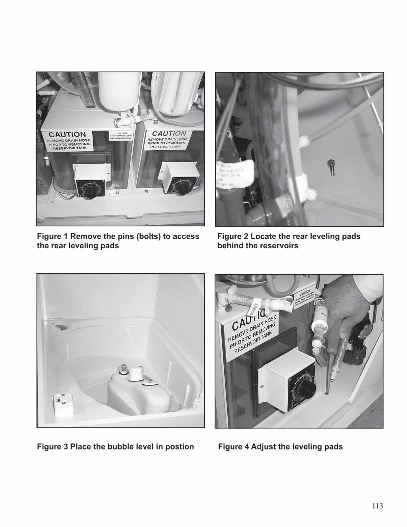
113
Figure 1 Remove the pins (bolts) to access Figure 2 Locate the rear leveling pads the rear leveling pads behind the reservoirs
Figure 3 Place the bubble level in postion Figure 4 Adjust the leveling pads
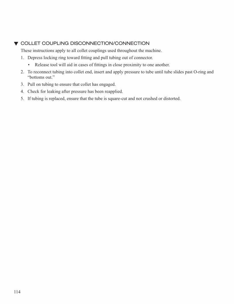
114
COLLET COUPLING DISCONNECTION/CONNECTION
These instructions apply to all collet couplings used throughout the machine.1. Depress locking ring toward fitting and pull tubing out of connector.
• Release tool will aid in cases of fittings in close proximity to one another.2. To reconnect tubing into collet end, insert and apply pressure to tube until tube slides past O-ring and
“bottoms out.”3. Pull on tubing to ensure that collet has engaged.4. Check for leaking after pressure has been reapplied.5. If tubing is replaced, ensure that the tube is square-cut and not crushed or distorted.
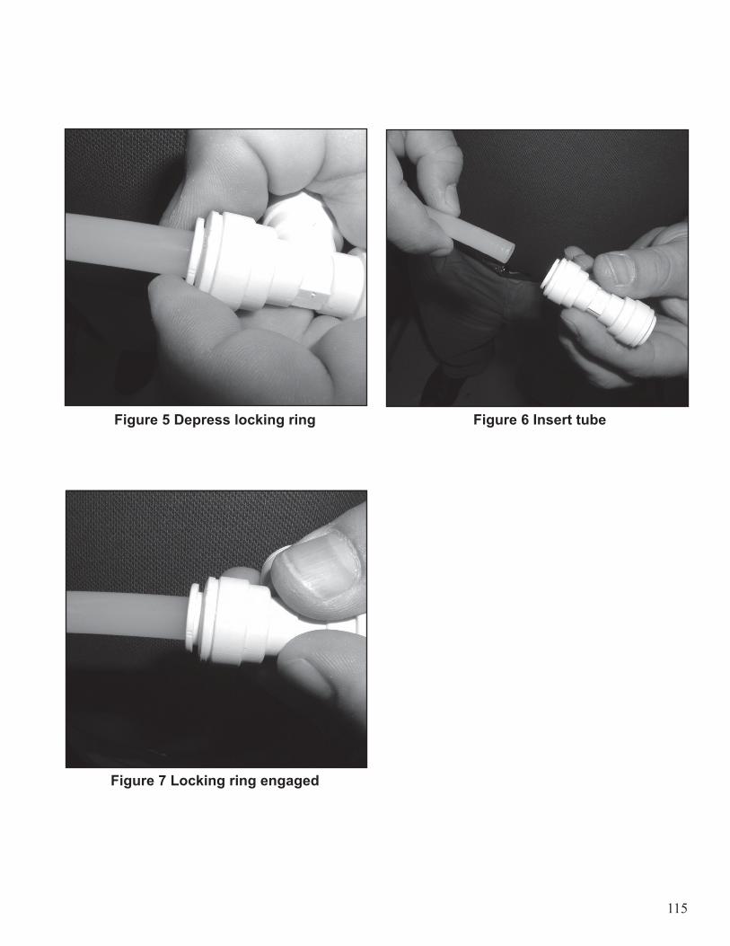
115
Figure 5 Depress locking ring Figure 6 Insert tube
Figure 7 Locking ring engaged
116
DISINFECTANT FILTER CARTRIDGE–REPLACE
The disinfectant filter must be changed at every disinfectant dump/load procedure.1. Place a container under the filter to catch any excess liquid.2. Disconnect the quick-connect fitting from the reservoir side of the filter.
Note: Check for lint/debris build up at the filter connections. Clean the filter connections before installing new filter.
3. Disconnect the quick-connect fitting from the pump side of the filter.4. Remove the filter cartridge and replace with a new MEDIVATORS cartridge.
• Position the filter with the arrows in the direction of flow, away from the reservoir.5. Re-connect the quick-connect fitting to the pump side of the filter. 6. Re-connect the quick-connect fitting to the reservoir side of the filter.7. Record the date of the filter change in the log book.
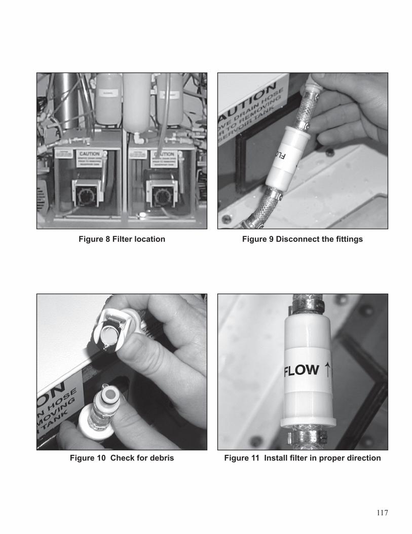
117
Figure 8 Filter location Figure 9 Disconnect the fittings
Figure 10 Check for debris Figure 11 Install filter in proper direction
118
INTERNAL 0.2 MICRON WATER FILTER–REMOVAL
The disinfector must be in idle state to perform this procedure. 1. Close the incoming water supply valve to the disinfector.2. Drain excess water from the filter housing.
• Place a container under the water filter inlet tube. • Disconnect the water filter inlet quick-connect from incoming water supply line.• Connect the accessory hose to the water filter inlet tube.• Open the filter bleeder valve and drain the water from the filter canister.
3. Remove the water filter cartridge.
Warning! Always wear gloves when handling the filter cartridge.
• Loosen the internal filter and remove the water filter housing.• Rotate the filter counterclockwise to unlock the filter cartridge.• Remove the filter and discard in accordance with institution guidelines.
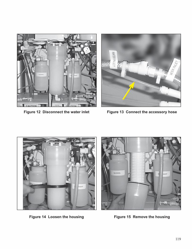
119
Figure 12 Disconnect the water inlet Figure 13 Connect the accessory hose
Figure 14 Loosen the housing Figure 15 Remove the housing
120
INTERNAL 2.0 MICRON WATER FILTER–REPLACE
1. Install the new water filter cartridge.
Warning! Always wear gloves when handling the filter cartridge.
• Insert the filter cartridge into the housing cap. • Turn the filter cartridge clockwise until the tabs locks into the cap.
2. Wipe the filter housing clean with a lint-free cloth.3. Install the filter housing onto the housing cap.
• Apply an NSF-approved silicone lubricant to the housing o-ring to aid assembly and sealing.• Tighten the housing into the cap by hand. Do not overtighten.
4. Reconnect the water inlet line.5. Close the bleeder valve on the filter housing.6. Turn on the water supply and check for leaks.7. Bleed any air from the housing using the bleeder valve.8. Perform the Water Line Disinfect procedure as described in the Operator Controls chapter.
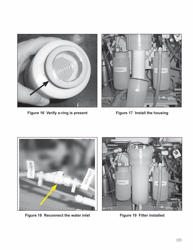
121
Figure 16 Verify o-ring is present Figure 17 Install the housing
Figure 18 Reconnect the water inlet Figure 19 Filter installed
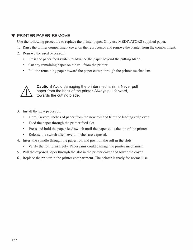
122
PRINTER PAPER–REMOVE
Use the following procedure to replace the printer paper. Only use MEDIVATORS supplied paper.1. Raise the printer compartment cover on the reprocessor and remove the printer from the compartment.2. Remove the used paper roll.
• Press the paper feed switch to advance the paper beyond the cutting blade.• Cut any remaining paper on the roll from the printer.• Pull the remaining paper toward the paper cutter, through the printer mechanism.
Caution! Avoid damaging the printer mechanism. Never pull paper from the back of the printer. Always pull forward, towards the cutting blade.
3. Install the new paper roll.• Unroll several inches of paper from the new roll and trim the leading edge even.• Feed the paper through the printer feed slot.• Press and hold the paper feed switch until the paper exits the top of the printer.• Release the switch after several inches are exposed.
4. Insert the spindle through the paper roll and position the roll in the slots. • Verify the roll turns freely. Paper jams could damage the printer mechanism.
5. Pull the exposed paper through the slot in the printer cover and lower the cover. 6. Replace the printer in the printer compartment. The printer is ready for normal use.
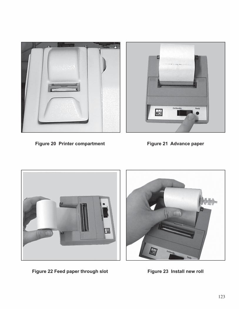
123
Figure 20 Printer compartment Figure 21 Advance paper
Figure 22 Feed paper through slot Figure 23 Install new roll
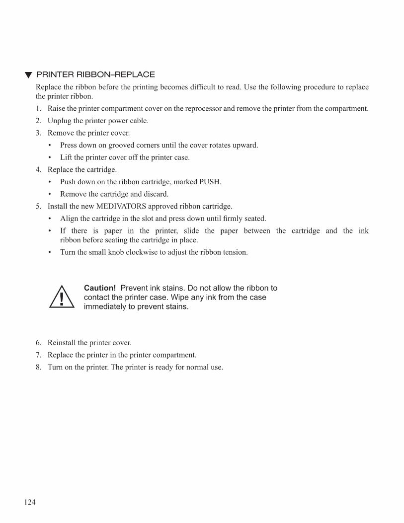
124
PRINTER RIBBON–REPLACE
Replace the ribbon before the printing becomes difficult to read. Use the following procedure to replace the printer ribbon.1. Raise the printer compartment cover on the reprocessor and remove the printer from the compartment.2. Unplug the printer power cable.3. Remove the printer cover.
• Press down on grooved corners until the cover rotates upward.• Lift the printer cover off the printer case.
4. Replace the cartridge.• Push down on the ribbon cartridge, marked PUSH.• Remove the cartridge and discard.
5. Install the new MEDIVATORS approved ribbon cartridge. • Align the cartridge in the slot and press down until firmly seated. • If there is paper in the printer, slide the paper between the cartridge and the ink
ribbon before seating the cartridge in place.• Turn the small knob clockwise to adjust the ribbon tension.
Caution! Prevent ink stains. Do not allow the ribbon to contact the printer case. Wipe any ink from the case immediately to prevent stains.
6. Reinstall the printer cover. 7. Replace the printer in the printer compartment. 8. Turn on the printer. The printer is ready for normal use.
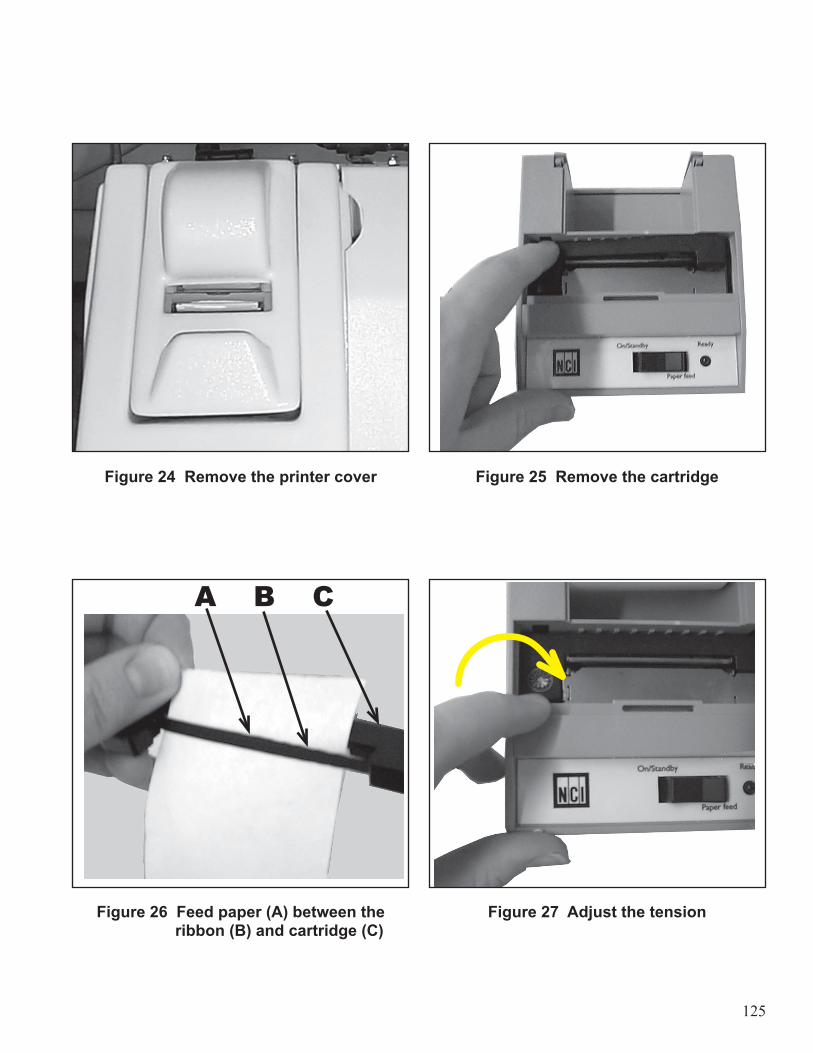
125
Figure 24 Remove the printer cover Figure 25 Remove the cartridge
Figure 26 Feed paper (A) between the Figure 27 Adjust the tension ribbon (B) and cartridge (C)
A B C
126
AIR FILTER–REPLACE
1. Locate the air filter.2. Disconnect the quick-connect fittings.3. Replace the old filter with a new filter.
• Verify that the inlet of the filter faces the compressor.4. Discard the old filter.5. Record the date of change in the log.
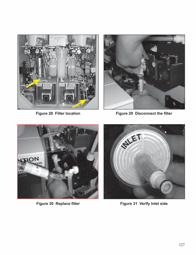
127
Figure 28 Filter location Figure 29 Disconnect the filter
Figure 30 Replace filter Figure 31 Verify Inlet side

128
3/4-INCH SOLENOID VALVE–CLEAN/SEAL REPLACEMENT
Solenoid valves should only need to be cleaned when they are not functioning properly. If cleaning fails to correct the valve problem, replace the entire valve assembly.1. Locate the solenoid valve.2. Remove the clip and solenoid coil to access the four bolts securing the assembly.3. Remove the four bolts from the valve assembly.4. Remove the internal components.
• Remove the plunger, seal, and spring.• Note the orientation of the spring as you remove it.
5. Clean or replace the plunger and the seal.6. Reinstall the plunger, seal, and spring.7. Reassemble the valve housing in reverse order.8. Install valve housing.
• Hand tighten all bolts, then tighten alternating corner bolts to 38 in/lbs.9. Install the solenoid coil and replace clip.• Ensure that the anti-chatter spring is in place.
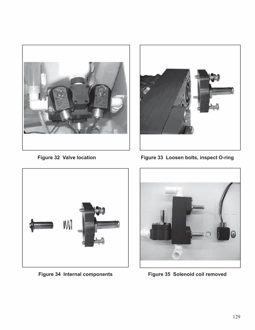
129
Figure 32 Valve location Figure 33 Loosen bolts, inspect O-ring
Figure 34 Internal components Figure 35 Solenoid coil removed
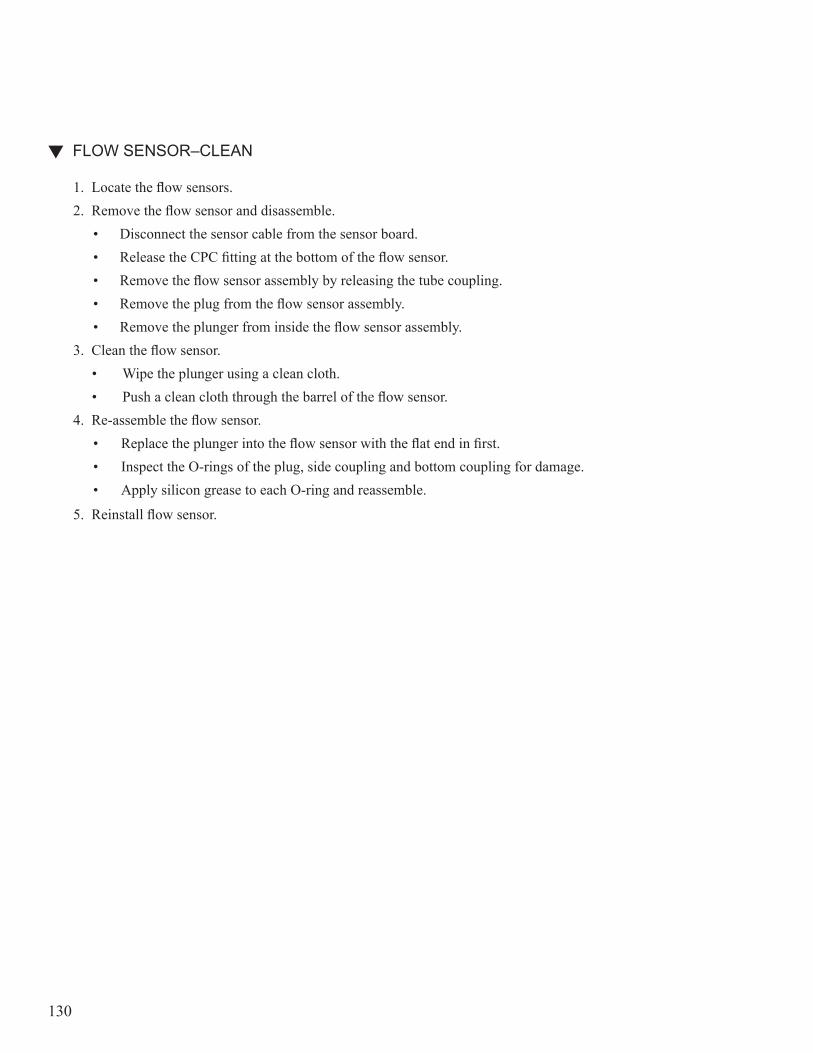
130
FLOW SENSOR–CLEAN
1. Locate the flow sensors.2. Remove the flow sensor and disassemble.
• Disconnect the sensor cable from the sensor board.• Release the CPC fitting at the bottom of the flow sensor.• Remove the flow sensor assembly by releasing the tube coupling.• Remove the plug from the flow sensor assembly.• Remove the plunger from inside the flow sensor assembly.
3. Clean the flow sensor.• Wipe the plunger using a clean cloth.• Push a clean cloth through the barrel of the flow sensor.
4. Re-assemble the flow sensor.• Replace the plunger into the flow sensor with the flat end in first.• Inspect the O-rings of the plug, side coupling and bottom coupling for damage.• Apply silicon grease to each O-ring and reassemble.
5. Reinstall flow sensor.
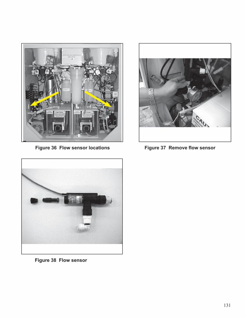
131
Figure 36 Flow sensor locations Figure 37 Remove flow sensor
Figure 38 Flow sensor
132
REMOVING THE DISINFECTANT RESERVOIR
The following procedure must be performed when both stations are idle.1. Remove the pins securing the reservoir.2. Disconnect the float sensor harness.3. Disconnect the red and white heater assembly wires (Feature Option).4. Disconnect the thermistor harness (Feature Option).5. Disconnect the disinfectant filter adaptor.6. Pull the disinfectant return hose out of the reservoir
7. Carefully slide the reservoir out.
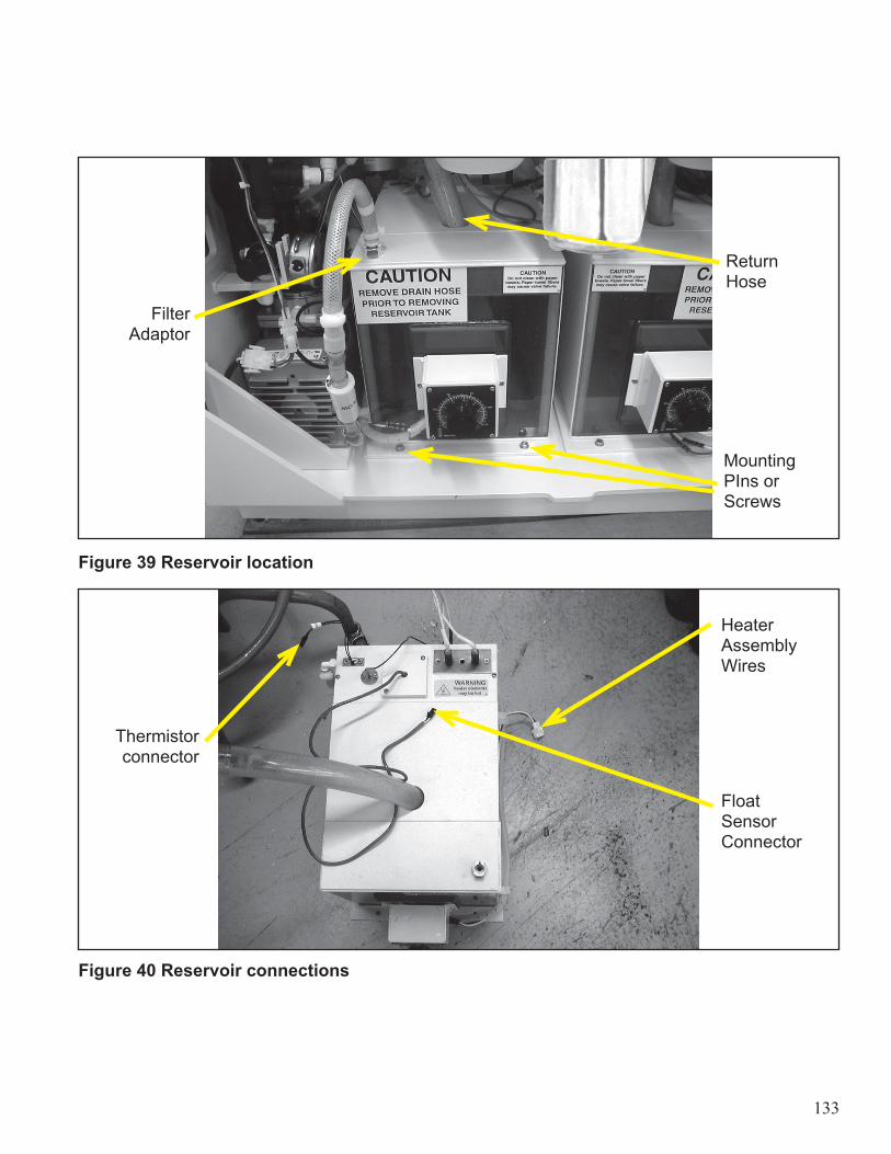
133
Figure 39 Reservoir location
Figure 40 Reservoir connections
FilterAdaptor
Thermistorconnector
ReturnHose
Mounting PIns or Screws
HeaterAssemblyWires
FloatSensorConnector

134
REPLACING THE FUSES
1. Unplug the reprocessor from the AC power receptacle.2. Remove the access screw from the front underside of the control panel console.3. Open control panel cover to access the electronics.4. Inspect visually or electrically to determine if fuse is damaged.5. Replace defective or blown fuses.6. Close control panel cover.7. Replace the access screw.8. Plug the power cord into the power receptacle.
Note: All fuses are slow blow. Do not use any other type.
Key 120V 240V SizeF1 3.15 A 3.15 A 5 x 20 mmF2 8.0 A 4.0 A 5 x 20 mmF3 3.15 A 2.0 A 5 x 20 mmPower Supply 1.5 A 1.5 A 3AG
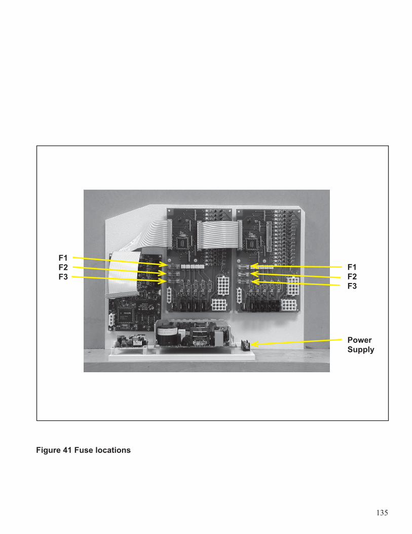
135
Figure 41 Fuse locations
F1F2 F3
F1F2F3
PowerSupply
136
LEAK TESTER OPTION–CHECK
1. Connect pressure gauge to leak test outlet in “A” upper chamber.2. Test the Leak Test Board.
• Select side “A”, SETUP 88,code 135• 51 ENTER, 54 ENTER to setup test• 95 ENTER. Display will show number 3C.• Gradually increase the pressure using the inflator. As the pressure increases, the display will read:
- 34 if pressure is greater than 1 psi- 31 if pressure is greater than 3 psi
• Gradually decrease the pressure using the toggle on the back of the inflator. As the pressure decreases, the display will read:- 35 if pressure is less than 3 psi- 3F if pressure is less than 1 psi
• Press CANCEL.3. Test Leak Tester system.
• Press 56 ENTER to verify 3 psi control pressure.• Press 57 ENTER to verify 1 psi hold pressure.• Bleed some air out of the system using the toggle and ensure that the tester main- tains 1 psi.• Press 50 ENTER to vent the system.
4. Internal Leak Test.• Press 56 ENTER.• Allow the pressure to stabilize.• Press 57 ENTER.• Monitor pressure for a minimum of 5 minutes. The pressure must not increase or decrease more than 4
mmHg.• Record the pressure and time on the test report.• Press 50 ENTER to vent the system
5. Repeat for Station “B”.• During the test of the Leak Test Board for Station “B”, the display will show the following readings:
- As the pressure increases, the display will read:1C if pressure is greater than 1 psi,8C if pressure is greater than 3 psi.
- As the pressure decreases, the display will read:9C if pressure is less than 3 psi, FC if pressure is less than 1 psi.
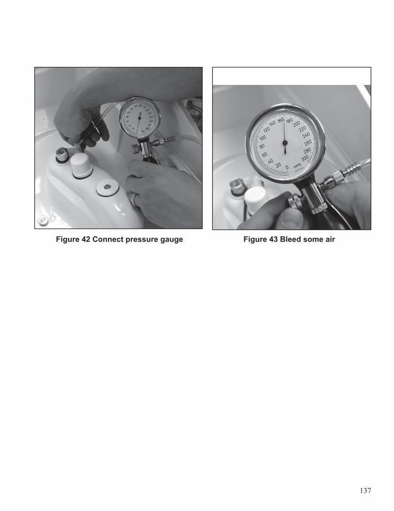
137
Figure 42 Connect pressure gauge Figure 43 Bleed some air

138
DRAINING CONDENSATION FROM AIR CHAMBER
Condensation will accumulate inside the air chamber. It is recommended that the air chamber be drained periodically. Perform the following procedure when the station is idle.1. Locate the air chamber on the back panel inside the cabinet.2. Pull the ring attached to the relief valve located at the bottom of the air chamber.3. Ensure that the purged air is free of condensation.4. Release the ring.
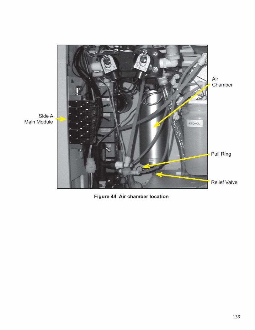
139
Side A Main Module
Air Chamber
Pull Ring
Relief Valve
Figure 44 Air chamber location
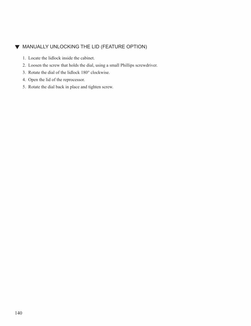
140
MANUALLY UNLOCKING THE LID (FEATURE OPTION)
1. Locate the lidlock inside the cabinet.2. Loosen the screw that holds the dial, using a small Phillips screwdriver.3. Rotate the dial of the lidlock 180° clockwise.4. Open the lid of the reprocessor.5. Rotate the dial back in place and tighten screw.
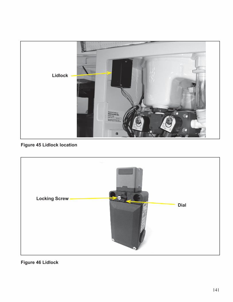
141
Figure 45 Lidlock location
Figure 46 Lidlock
Locking ScrewDial
Lidlock
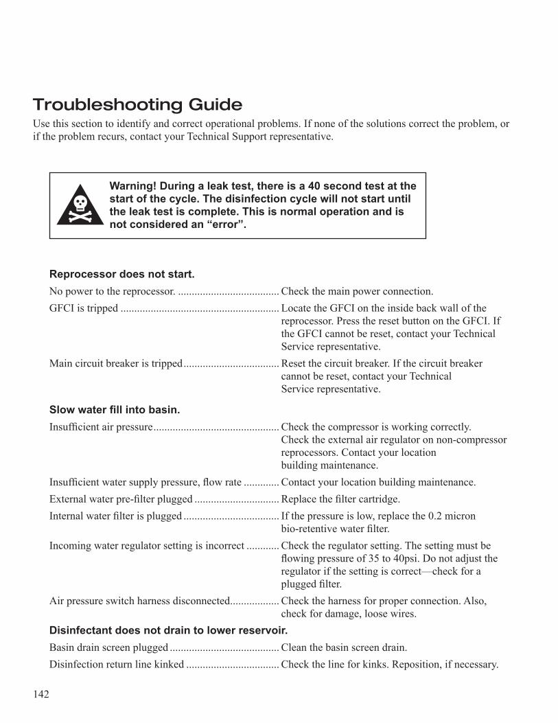
142
Troubleshooting GuideUse this section to identify and correct operational problems. If none of the solutions correct the problem, or if the problem recurs, contact your Technical Support representative.
Warning! During a leak test, there is a 40 second test at the start of the cycle. The disinfection cycle will not start until the leak test is complete. This is normal operation and is not considered an “error”.
Reprocessor does not start.No power to the reprocessor. ..................................... Check the main power connection.GFCI is tripped .......................................................... Locate the GFCI on the inside back wall of the .................................................................................... reprocessor. Press the reset button on the GFCI. If .................................................................................... the GFCI cannot be reset, contact your Technical .................................................................................... Service representative.Main circuit breaker is tripped ................................... Reset the circuit breaker. If the circuit breaker .................................................................................... cannot be reset, contact your Technical .................................................................................... Service representative.
Slow water fill into basin.Insufficient air pressure .............................................. Check the compressor is working correctly. .................................................................................... Check the external air regulator on non-compressor .................................................................................... reprocessors. Contact your location .................................................................................... building maintenance.Insufficient water supply pressure, flow rate ............. Contact your location building maintenance.External water pre-filter plugged ............................... Replace the filter cartridge.Internal water filter is plugged ................................... If the pressure is low, replace the 0.2 micron .................................................................................... bio-retentive water filter.Incoming water regulator setting is incorrect ............ Check the regulator setting. The setting must be .................................................................................... flowing pressure of 35 to 40psi. Do not adjust the .................................................................................... regulator if the setting is correct—check for a .................................................................................... plugged filter.Air pressure switch harness disconnected .................. Check the harness for proper connection. Also, .................................................................................... check for damage, loose wires.Disinfectant does not drain to lower reservoir.Basin drain screen plugged ........................................ Clean the basin screen drain.Disinfection return line kinked .................................. Check the line for kinks. Reposition, if necessary.

143
Water flows constantly from hook-ups.Water valve not sealing correctly ............................... Shut off the water supply and contact .................................................................................... customer support.
Water does not drain from basin during flush or rinse.Drain too high ........................................................... Drain must be below the reprocessor outlet for .................................................................................... proper flow.External drain line kinked .......................................... Repair the drain line.Drain line plugged ...................................................... Clean the drain line or replace the line, if necessary.Basin drain screen plugged ........................................ Clean the basin screen drain.
No air after cycle.Incorrect air program setting ...................................... Check the air setting in the Setup menu (Setup 5).
LCD screen unreadable.Contrast out of adjustment, screen failed ................... Contact your customer support.
Printing unreadable.Printer ribbon is infrequently used ............................. Press the paper feed switch to advance the printer ribbon to a new section.Printer ribbon worn .................................................... Replace the printer ribbon.
Printer does not operate.No power to machine ................................................. Check the main power connection. Check the .................................................................................... GFCI. Reset if tripped. Check the main circuit .................................................................................... breaker. Reset if tripped.Printer switch turned “OFF” ...................................... Turn the printer switch to the “ON” position.Power supply unplugged ............................................ Check the power supply connection is plugged into .................................................................................... the outlet in the reprocessor.Printer ribbon is jammed ............................................ Check the printer ribbon. Open the printer and re- .................................................................................... align the jammed ribbon. Rotate the knob to adjust .................................................................................... the ribbon tension.Printer paper is jammed ............................................. Check the printer paper. Open the printer and .................................................................................... remove the paper jam. Press the paper feed switch .................................................................................... to feed paper through the printer cover.Printer connection is disconnected ............................. Check the printer cable connection. Verify the .................................................................................... connector is plugged in and seated tightly.Printer damaged or defective ..................................... Contact your customer support.
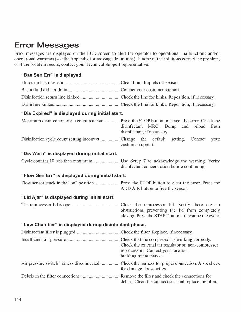
144
Error MessagesError messages are displayed on the LCD screen to alert the operator to operational malfunctions and/or operational warnings (see the Appendix for message definitions). If none of the solutions correct the problem, or if the problem recurs, contact your Technical Support representative.
“Bas Sen Err” is displayed.Fluids on basin sensor ................................................Clean fluid droplets off sensor.Basin fluid did not drain .............................................Contact your customer support.Disinfection return line kinked ..................................Check the line for kinks. Reposition, if necessary.Drain line kinked ........................................................Check the line for kinks. Reposition, if necessary.
“Dis Expired” is displayed during initial start.Maximum disinfection cycle count reached ..............Press the STOP button to cancel the error. Check the ....................................................................................disinfectant MRC. Dump and reload fresh ....................................................................................disinfectant, if necessary.Disinfection cycle count setting incorrect ..................Change the default setting. Contact your ....................................................................................customer support.
“Dis Warn” is displayed during initial start.Cycle count is 10 less than maximum ........................Use Setup 7 to acknowledge the warning. Verify ....................................................................................disinfectant concentration before continuing.
“Flow Sen Err” is displayed during initial start.Flow sensor stuck in the “on” position ......................Press the STOP button to clear the error. Press the ....................................................................................ADD AIR button to free the sensor.
“Lid Ajar” is displayed during initial start.The reprocessor lid is open ........................................Close the reprocessor lid. Verify there are no ....................................................................................obstructions preventing the lid from completely ....................................................................................closing. Press the START button to resume the cycle.
“Low Chamber” is displayed during disinfectant phase.Disinfectant filter is plugged ......................................Check the filter. Replace, if necessary.Insufficient air pressure ..............................................Check that the compressor is working correctly. ....................................................................................Check the external air regulator on non-compressor ....................................................................................reprocessors. Contact your location ....................................................................................building maintenance.Air pressure switch harness disconnected ..................Check the harness for proper connection. Also, check ....................................................................................for damage, loose wires.Debris in the filter connections ..................................Remove the filter and check the connections for ....................................................................................debris. Clean the connections and replace the filter.
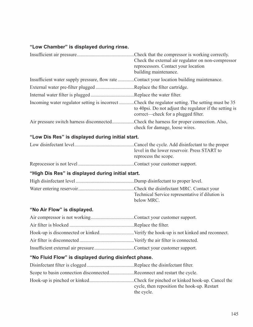
145
“Low Chamber” is displayed during rinse.Insufficient air pressure ..............................................Check that the compressor is working correctly. ....................................................................................Check the external air regulator on non-compressor ....................................................................................reprocessors. Contact your location ....................................................................................building maintenance.Insufficient water supply pressure, flow rate .............Contact your location building maintenance.External water pre-filter plugged ...............................Replace the filter cartridge.Internal water filter is plugged ...................................Replace the water filter.Incoming water regulator setting is incorrect ............Check the regulator setting. The setting must be 35 ....................................................................................to 40psi. Do not adjust the regulator if the setting is ....................................................................................correct—check for a plugged filter.Air pressure switch harness disconnected ..................Check the harness for proper connection. Also, ....................................................................................check for damage, loose wires.
“Low Dis Res” is displayed during initial start.Low disinfectant level ................................................Cancel the cycle. Add disinfectant to the proper ....................................................................................level in the lower reservoir. Press START to ....................................................................................reprocess the scope.Reprocessor is not level .............................................Contact your customer support.
“High Dis Res” is displayed during initial start.High disinfectant level ...............................................Dump disinfectant to proper level. Water entering reservoir .............................................Check the disinfectant MRC. Contact your ....................................................................................Technical Service representative if dilution is ....................................................................................below MRC.
“No Air Flow” is displayed.Air compressor is not working ...................................Contact your customer support.Air filter is blocked ....................................................Replace the filter.Hook-up is disconnected or kinked ............................Verify the hook-up is not kinked and reconnect.Air filter is disconnected ............................................Verify the air filter is connected.Insufficient external air pressure ................................Contact your customer support.
“No Fluid Flow” is displayed during disinfect phase.Disinfectant filter is clogged ......................................Replace the disinfectant filter.Scope to basin connection disconnected ....................Reconnect and restart the cycle.Hook-up is pinched or kinked ....................................Check for pinched or kinked hook-up. Cancel the ....................................................................................cycle, then reposition the hook-up. Restart ....................................................................................the cycle.
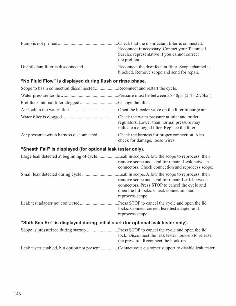
146
Pump is not primed ....................................................Check that the disinfectant filter is connected. ....................................................................................Reconnect if necessary. Contact your Technical ....................................................................................Service representative if you cannot correct ....................................................................................the problem.Disinfectant filter is disconnected ..............................Reconnect the disinfectant filter. Scope channel is ....................................................................................blocked. Remove scope and send for repair.
“No Fluid Flow” is displayed during flush or rinse phase.Scope to basin connection disconnected ....................Reconnect and restart the cycle.Water pressure too low ...............................................Pressure must be between 35-40psi (2.4 - 2.75bar).Prefilter / internal filter clogged .................................Change the filter.Air lock in the water filter ..........................................Open the bleeder valve on the filter to purge air.Water filter is clogged ................................................Check the water pressure at inlet and outlet ....................................................................................regulators. Lower than normal pressure may ....................................................................................indicate a clogged filter. Replace the filter.Air pressure switch harness disconnected ..................Check the harness for proper connection. Also, ....................................................................................check for damage, loose wires.
“Sheath Fail” is displayed (for optional leak tester only).Large leak detected at beginning of cycle ..................Leak in scope. Allow the scope to reprocess, then ....................................................................................remove scope and send for repair. Leak between ....................................................................................connectors. Check connection and reprocess scope.Small leak detected during cycle ...............................Leak in scope. Allow the scope to reprocess, then ....................................................................................remove scope and send for repair. Leak between ....................................................................................connectors. Press STOP to cancel the cycle and ....................................................................................open the lid locks. Check connection and ....................................................................................reprocess scope.Leak test adapter not connected .................................Press STOP to cancel the cycle and open the lid ....................................................................................locks. Connect correct leak test adapter and ....................................................................................reprocess scope.
“Shth Sen Err” is displayed during initial start (for optional leak tester only).Scope is pressurized during startup ............................Press STOP to cancel the cycle and open the lid ....................................................................................lock. Disconnect the leak tester hook-up to release ....................................................................................the pressure. Reconnect the hook-up.Leak tester enabled, but option not present ...............Contact your customer support to disable leak tester.

147
APPENDIX
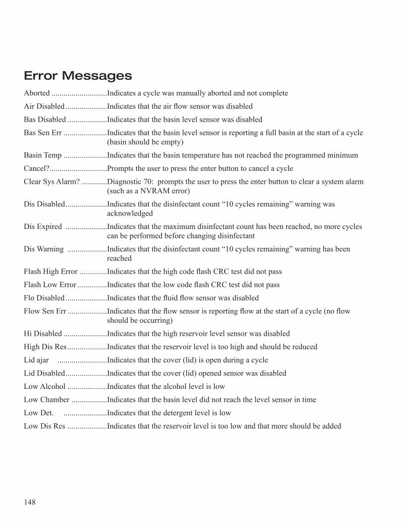
148
Error MessagesAborted ............................Indicates a cycle was manually aborted and not complete
Air Disabled .....................Indicates that the air flow sensor was disabled
Bas Disabled ....................Indicates that the basin level sensor was disabled
Bas Sen Err ......................Indicates that the basin level sensor is reporting a full basin at the start of a cycle (basin should be empty)
Basin Temp ......................Indicates that the basin temperature has not reached the programmed minimum
Cancel? .............................Prompts the user to press the enter button to cancel a cycle
Clear Sys Alarm? .............Diagnostic 70: prompts the user to press the enter button to clear a sys tem alarm (such as a NVRAM error)
Dis Disabled .....................Indicates that the disinfectant count “10 cycles remaining” warning was acknowledged
Dis Expired .....................Indicates that the maximum disinfectant count has been reached, no more cycles can be performed before changing disinfectant
Dis Warning ....................Indicates that the disinfectant count “10 cycles remaining” warning has been reached
Flash High Error ..............Indicates that the high code flash CRC test did not pass
Flash Low Error ...............Indicates that the low code flash CRC test did not pass
Flo Disabled .....................Indicates that the fluid flow sensor was disabled
Flow Sen Err ....................Indicates that the flow sensor is reporting flow at the start of a cycle (no flow should be occurring)
Hi Disabled ......................Indicates that the high reservoir level sensor was disabled
High Dis Res ....................Indicates that the reservoir level is too high and should be reduced
Lid ajar .........................Indicates that the cover (lid) is open during a cycle
Lid Disabled .....................Indicates that the cover (lid) opened sensor was disabled
Low Alcohol ....................Indicates that the alcohol level is low
Low Chamber ..................Indicates that the basin level did not reach the level sensor in time
Low Det. ......................Indicates that the detergent level is low
Low Dis Res ....................Indicates that the reservoir level is too low and that more should be added
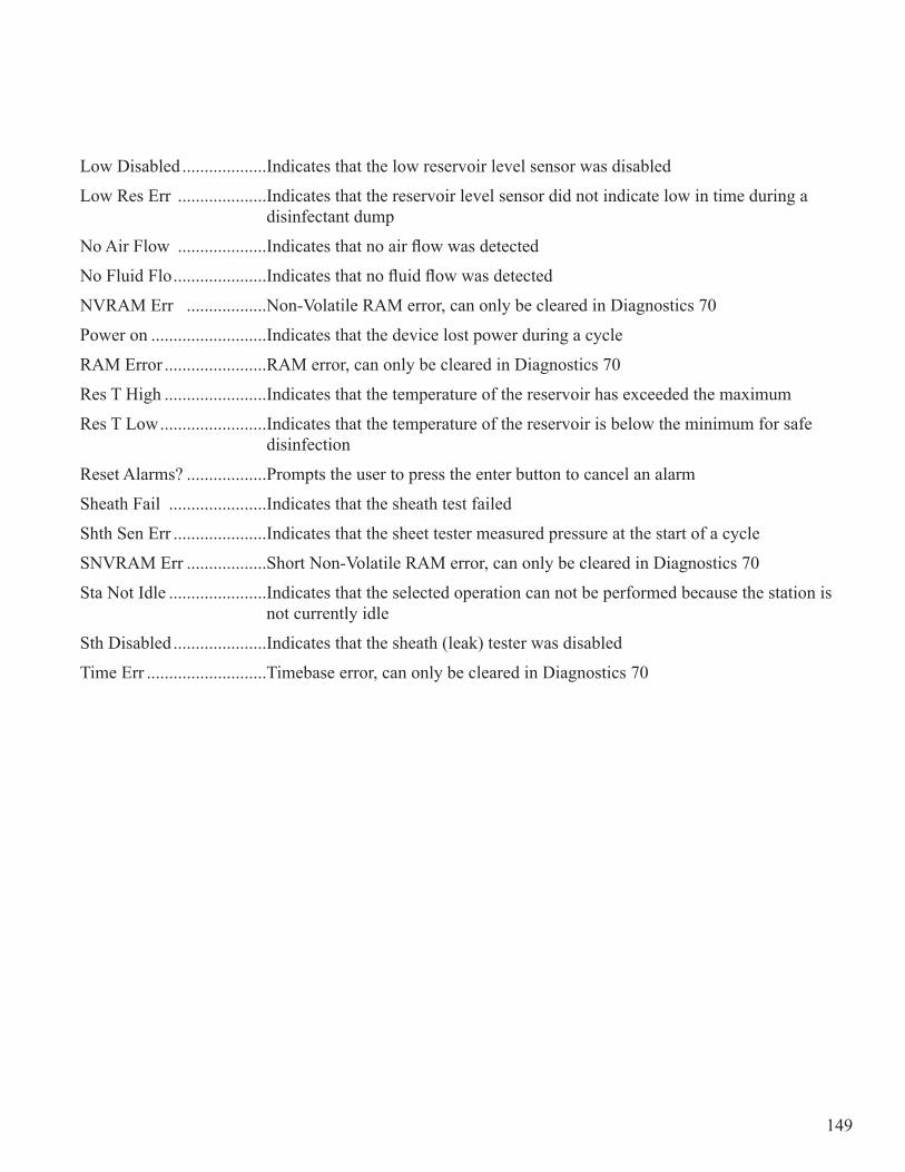
149
Low Disabled ...................Indicates that the low reservoir level sensor was disabled
Low Res Err ....................Indicates that the reservoir level sensor did not indicate low in time during a disinfectant dump
No Air Flow ....................Indicates that no air flow was detected
No Fluid Flo .....................Indicates that no fluid flow was detected
NVRAM Err ..................Non-Volatile RAM error, can only be cleared in Diagnostics 70
Power on ..........................Indicates that the device lost power during a cycle
RAM Error .......................RAM error, can only be cleared in Diagnostics 70
Res T High .......................Indicates that the temperature of the reservoir has exceeded the maxi mum
Res T Low ........................Indicates that the temperature of the reservoir is below the minimum for safe disinfection
Reset Alarms? ..................Prompts the user to press the enter button to cancel an alarm
Sheath Fail ......................Indicates that the sheath test failed
Shth Sen Err .....................Indicates that the sheet tester measured pressure at the start of a cycle
SNVRAM Err ..................Short Non-Volatile RAM error, can only be cleared in Diagnostics 70
Sta Not Idle ......................Indicates that the selected operation can not be performed because the station is not currently idle
Sth Disabled .....................Indicates that the sheath (leak) tester was disabled
Time Err ...........................Timebase error, can only be cleared in Diagnostics 70
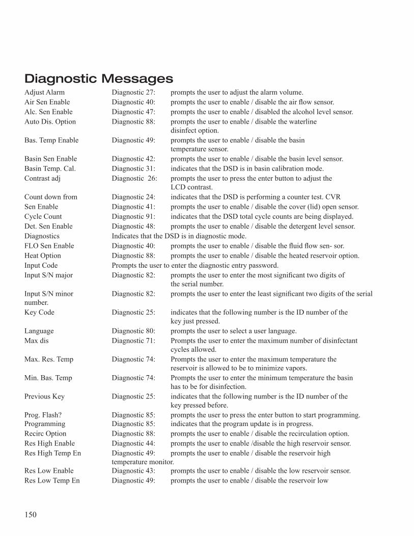
150
Diagnostic MessagesAdjust Alarm Diagnostic 27: prompts the user to adjust the alarm volume.Air Sen Enable Diagnostic 40: prompts the user to enable / disable the air flow sensor. Alc. Sen Enable Diagnostic 47: prompts the user to enable / disabled the alcohol level sensor.Auto Dis. Option Diagnostic 88: prompts the user to enable / disable the waterline disinfect option.Bas. Temp Enable Diagnostic 49: prompts the user to enable / disable the basin temperature sensor.Basin Sen Enable Diagnostic 42: prompts the user to enable / disable the basin level sensor.Basin Temp. Cal. Diagnostic 31: indicates that the DSD is in basin calibration mode. Contrast adj Diagnostic 26: prompts the user to press the enter button to adjust the LCD contrast.Count down from Diagnostic 24: indicates that the DSD is performing a counter test. CVR Sen Enable Diagnostic 41: prompts the user to enable / disable the cover (lid) open sensor.Cycle Count Diagnostic 91: indicates that the DSD total cycle counts are being displayed.Det. Sen Enable Diagnostic 48: prompts the user to enable / disable the detergent level sensor.Diagnostics Indicates that the DSD is in diagnostic mode.FLO Sen Enable Diagnostic 40: prompts the user to enable / disable the fluid flow sen- sor.Heat Option Diagnostic 88: prompts the user to enable / disable the heated reservoir option.Input Code Prompts the user to enter the diagnostic entry password.Input S/N major Diagnostic 82: prompts the user to enter the most significant two digits of the serial number.Input S/N minor Diagnostic 82: prompts the user to enter the least significant two digits of the serial number.Key Code Diagnostic 25: indicates that the following number is the ID number of the key just pressed.Language Diagnostic 80: prompts the user to select a user language.Max dis Diagnostic 71: Prompts the user to enter the maximum number of disinfectant cycles allowed.Max. Res. Temp Diagnostic 74: Prompts the user to enter the maximum temperature the reservoir is allowed to be to minimize vapors.Min. Bas. Temp Diagnostic 74: Prompts the user to enter the minimum temperature the basin has to be for disinfection.Previous Key Diagnostic 25: indicates that the following number is the ID number of the key pressed before.Prog. Flash? Diagnostic 85: prompts the user to press the enter button to start programming. Programming Diagnostic 85: indicates that the program update is in progress. Recirc Option Diagnostic 88: prompts the user to enable / disable the recirculation option.Res High Enable Diagnostic 44: prompts the user to enable /disable the high reservoir sensor.Res High Temp En Diagnostic 49: prompts the user to enable / disable the reservoir high temperature monitor.Res Low Enable Diagnostic 43: prompts the user to enable / disable the low reservoir sensor.Res Low Temp En Diagnostic 49: prompts the user to enable / disable the reservoir low

151
temperature monitor.Res. Temp. Cal. Diagnostic 32: indicates that the DSD is in reservoir calibration mode.Reset programs? Diagnostic 72: prompts the user to press the enter button to clear all user programs.Set A purge Secs Diagnostic 63: prompts the user to enter the air purge time in sec- onds.Set D Drain Secs Diagnostic 61: prompts the user to enter the disinfectant drain time in seconds.Set D Fill Secs Diagnostic 62: prompts the user to enter the disinfectant fill time in seconds.Set D Pulse Secs Diagnostic 64: prompts the user to enter the disinfectant pulse time in seconds.Set D Top Secs Diagnostic 67: prompts the user to enter the disinfectant top-off time in seconds.Set Dis. Hold Diagnostic 69: prompts the user to enter the water line disinfectant hold time in hours and minutes.Set Extra Air Diagnostic 65: prompts the user to enter the add extra air time in seconds.Set F purge Secs Diagnostic 63: prompts the user to enter the fluid purge time in seconds.Set Idle State? Diagnostic 89: prompts the user to press the enter button to jump to the idle state.Set P Drain Secs Diagnostic 66: prompts the user to enter the short rinse partial drain time in seconds.Set P Fill Secs Diagnostic 66: prompts the user to enter the short rinse partial fill time in seconds.Set R Drain Secs Diagnostic 61: prompts the user to enter the rinse drain time in seconds.Set R Fill Secs Diagnostic 62: prompts the user to enter the rinse fill time in seconds. Set R Rinse Secs Diagnostic 68: prompts the user to enter the short rinse recirc time in seconds.Set R Top Secs Diagnostic 67: prompts the user to enter the rinse top-off time in seconds.Set Temp. to 10C Diagnostic 31 and 32: prompts the user to set the thermistor to 10C. Set Temp. to 30C Diagnostic 31: prompts the user to set the thermistor to 30C.Shth Sen Enable Diagnostic 45: prompts the user to enable / disable the sheath (leak) tester optionTemp Option Diagnostic 88: prompts the user to enable/disable the temperature monitoring option.Testing Sensors ................Diagnostic 94: indicates that the current sensor values are being dis- played.Time Limit: ......................Diagnostic 81: prompts the user to enter the programmable time limits.
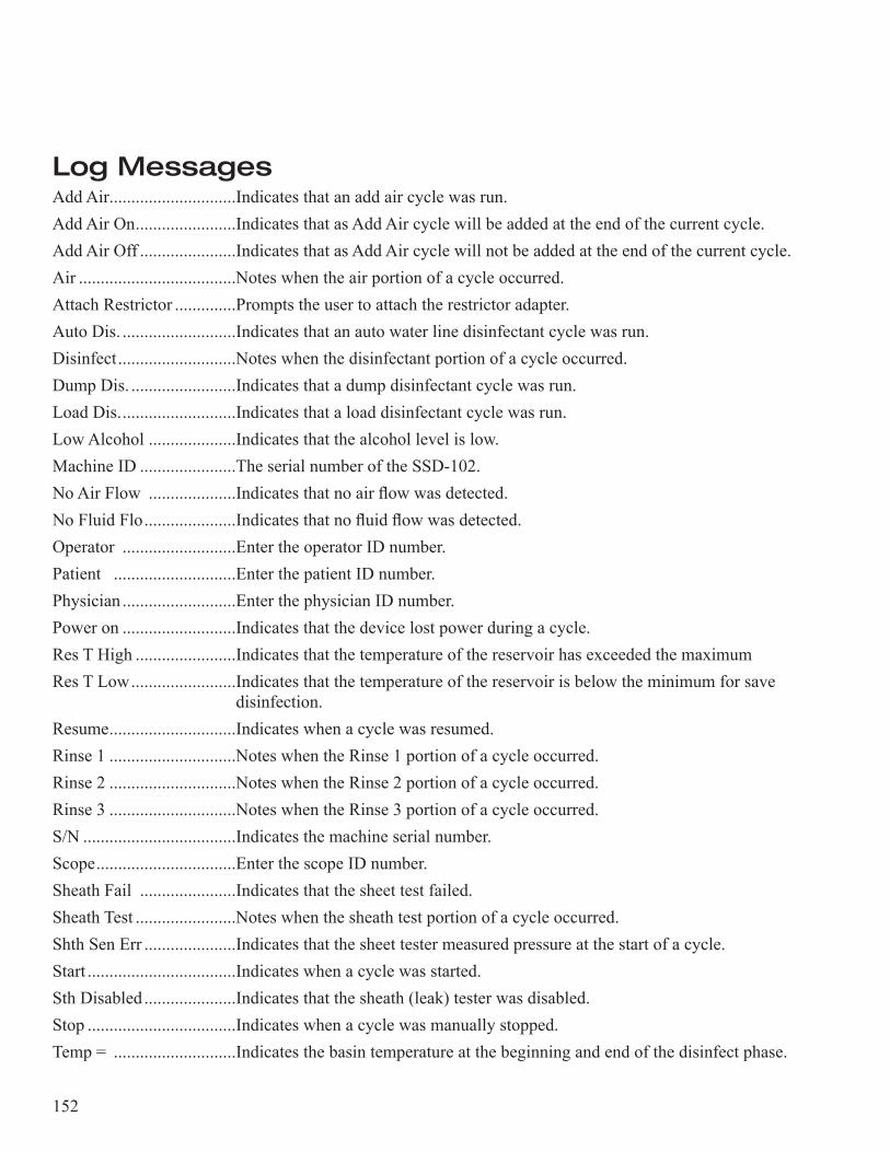
152
Log MessagesAdd Air.............................Indicates that an add air cycle was run.Add Air On .......................Indicates that as Add Air cycle will be added at the end of the current cycle.Add Air Off ......................Indicates that as Add Air cycle will not be added at the end of the cur rent cycle.Air ....................................Notes when the air portion of a cycle occurred.Attach Restrictor ..............Prompts the user to attach the restrictor adapter.Auto Dis. ..........................Indicates that an auto water line disinfectant cycle was run.Disinfect ...........................Notes when the disinfectant portion of a cycle occurred.Dump Dis. ........................Indicates that a dump disinfectant cycle was run.Load Dis. ..........................Indicates that a load disinfectant cycle was run.Low Alcohol ....................Indicates that the alcohol level is low.Machine ID ......................The serial number of the SSD-102.No Air Flow ....................Indicates that no air flow was detected.No Fluid Flo .....................Indicates that no fluid flow was detected.Operator ..........................Enter the operator ID number.Patient ............................Enter the patient ID number.Physician ..........................Enter the physician ID number.Power on ..........................Indicates that the device lost power during a cycle.Res T High .......................Indicates that the temperature of the reservoir has exceeded the maxi mumRes T Low ........................Indicates that the temperature of the reservoir is below the minimum for save
disinfection.Resume .............................Indicates when a cycle was resumed.Rinse 1 .............................Notes when the Rinse 1 portion of a cycle occurred.Rinse 2 .............................Notes when the Rinse 2 portion of a cycle occurred.Rinse 3 .............................Notes when the Rinse 3 portion of a cycle occurred.S/N ...................................Indicates the machine serial number.Scope ................................Enter the scope ID number.Sheath Fail ......................Indicates that the sheet test failed.Sheath Test .......................Notes when the sheath test portion of a cycle occurred.Shth Sen Err .....................Indicates that the sheet tester measured pressure at the start of a cycle.Start ..................................Indicates when a cycle was started.Sth Disabled .....................Indicates that the sheath (leak) tester was disabled.Stop ..................................Indicates when a cycle was manually stopped.Temp = ............................Indicates the basin temperature at the beginning and end of the disin fect phase.
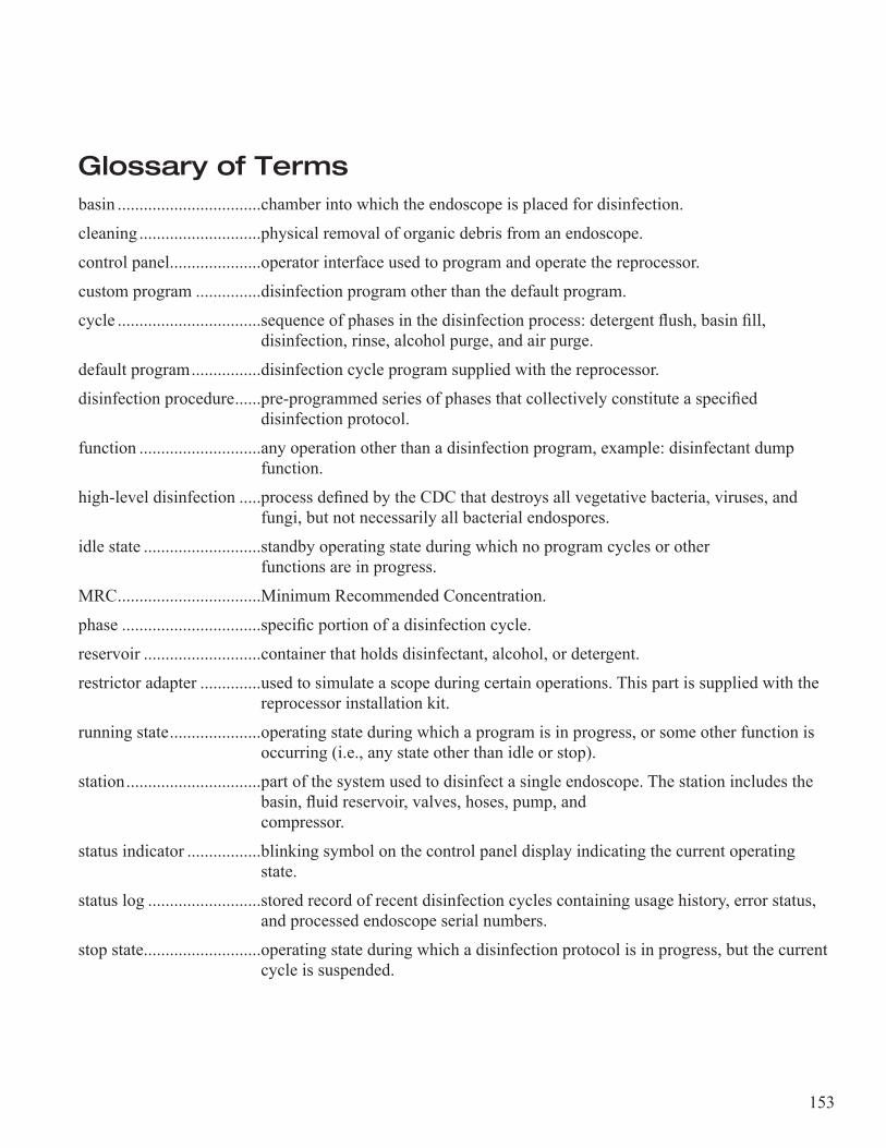
153
Glossary of Termsbasin .................................chamber into which the endoscope is placed for disinfection.
cleaning ............................physical removal of organic debris from an endoscope.
control panel .....................operator interface used to program and operate the reprocessor.
custom program ...............disinfection program other than the default program.
cycle .................................sequence of phases in the disinfection process: detergent flush, basin fill, disinfection, rinse, alcohol purge, and air purge.
default program ................disinfection cycle program supplied with the reprocessor.
disinfection procedure ......pre-programmed series of phases that collectively constitute a specified disinfection protocol.
function ............................any operation other than a disinfection program, example: disinfectant dump function.
high-level disinfection .....process defined by the CDC that destroys all vegetative bacteria, viruses, and fungi, but not necessarily all bacterial endospores.
idle state ...........................standby operating state during which no program cycles or other functions are in progress.
MRC .................................Minimum Recommended Concentration.
phase ................................specific portion of a disinfection cycle.
reservoir ...........................container that holds disinfectant, alcohol, or detergent.
restrictor adapter ..............used to simulate a scope during certain operations. This part is supplied with the reprocessor installation kit.
running state .....................operating state during which a program is in progress, or some other function is occurring (i.e., any state other than idle or stop).
station ...............................part of the system used to disinfect a single endoscope. The station includes the basin, fluid reservoir, valves, hoses, pump, and compressor.
status indicator .................blinking symbol on the control panel display indicating the current operating state.
status log ..........................stored record of recent disinfection cycles containing usage history, error status, and processed endoscope serial numbers.
stop state ...........................operating state during which a disinfection protocol is in progress, but the current cycle is suspended.
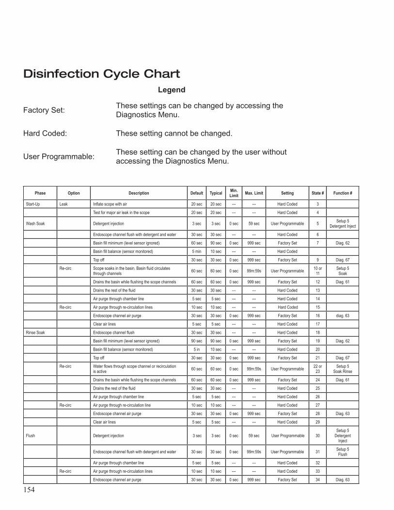
154
Disinfection Cycle ChartLegend
Factory Set: These settings can be changed by accessing the Diagnostics Menu.
Hard Coded: These setting cannot be changed.
User Programmable: These setting can be changed by the user without accessing the Diagnostics Menu.
Phase Option Description Default Typical Min. Limit Max. Limit Setting State # Function #
Start-Up Leak Inflate scope with air 20 sec 20 sec --- --- Hard Coded 3
Test for major air leak in the scope 20 sec 20 sec --- --- Hard Coded 4
Wash Soak Detergent injection 3 sec 3 sec 0 sec 59 sec User Programmable 5 Setup 5 Detergent Inject
Endoscope channel flush with detergent and water 30 sec 30 sec --- --- Hard Coded 6
Basin fill minimum (level sensor ignored) 60 sec 90 sec 0 sec 999 sec Factory Set 7 Diag. 62
Basin fill balance (sensor monitored) 5 min 10 sec --- --- Hard Coded
Top off 30 sec 30 sec 0 sec 999 sec Factory Set 9 Diag. 67
Re-circ Scope soaks in the basin. Basin fluid circulates through channels 60 sec 60 sec 0 sec 99m:59s User Programmable 10 or
11Setup 5
Soak
Drains the basin while flushing the scope channels 60 sec 60 sec 0 sec 999 sec Factory Set 12 Diag. 61
Drains the rest of the fluid 30 sec 30 sec --- --- Hard Coded 13
Air purge through chamber line 5 sec 5 sec --- --- Hard Coded 14
Re-circ Air purge through re-circulation lines 10 sec 10 sec --- --- Hard Coded 15
Endoscope channel air purge 30 sec 30 sec 0 sec 999 sec Factory Set 16 diag. 63
Clear air lines 5 sec 5 sec --- --- Hard Coded 17
Rinse Soak Endoscope channel flush 30 sec 30 sec --- --- Hard Coded 18
Basin fill minimum (level sensor ignored) 90 sec 90 sec 0 sec 999 sec Factory Set 19 Diag. 62
Basin fill balance (sensor monitored) 5 in 10 sec --- --- Hard Coded 20
Top off 30 sec 30 sec 0 sec 999 sec Factory Set 21 Diag. 67
Re-circ Water flows through scope channel or recirculation is active 60 sec 60 sec 0 sec 99m:59s User Programmable 22 or
23Setup 5
Soak Rinse
Drains the basin while flushing the scope channels 60 sec 60 sec 0 sec 999 sec Factory Set 24 Diag. 61
Drains the rest of the fluid 30 sec 30 sec --- --- Hard Coded 25
Air purge through chamber line 5 sec 5 sec --- --- Hard Coded 26
Re-circ Air purge through re-circulation line 10 sec 10 sec --- --- Hard Coded 27
Endoscope channel air purge 30 sec 30 sec 0 sec 999 sec Factory Set 28 Diag. 63
Clear air lines 5 sec 5 sec --- --- Hard Coded 29
Flush Detergent injection 3 sec 3 sec 0 sec 59 sec User Programmable 30Setup 5
Detergent Inject
Endoscope channel flush with detergent and water 30 sec 30 sec 0 sec 99m:59s User Programmable 31 Setup 5 Flush
Air purge through chamber line 5 sec 5 sec --- --- Hard Coded 32
Re-circ Air purge through re-circulation lines 10 sec 10 sec --- --- Hard Coded 33
Endoscope channel air purge 30 sec 30 sec 0 sec 999 sec Factory Set 34 Diag. 63
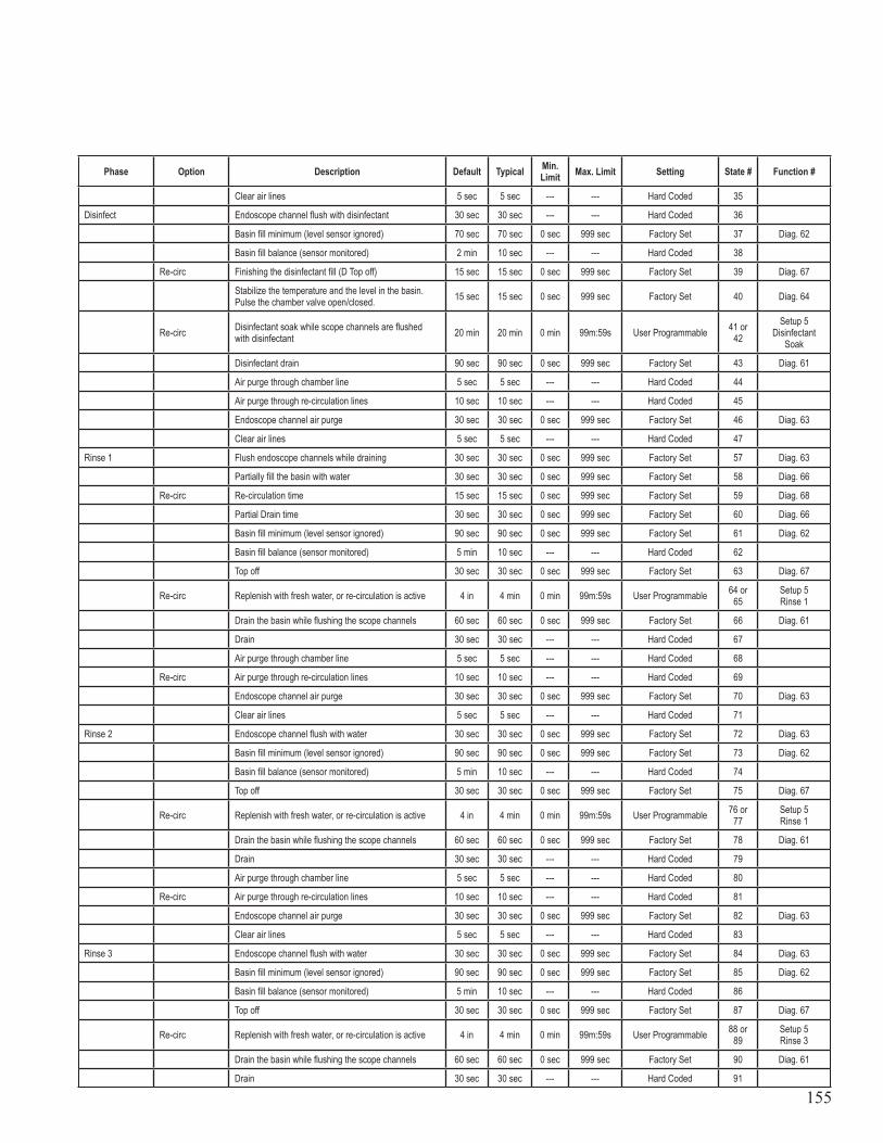
155
Phase Option Description Default Typical Min. Limit Max. Limit Setting State # Function #
Clear air lines 5 sec 5 sec --- --- Hard Coded 35
Disinfect Endoscope channel flush with disinfectant 30 sec 30 sec --- --- Hard Coded 36
Basin fill minimum (level sensor ignored) 70 sec 70 sec 0 sec 999 sec Factory Set 37 Diag. 62
Basin fill balance (sensor monitored) 2 min 10 sec --- --- Hard Coded 38
Re-circ Finishing the disinfectant fill (D Top off) 15 sec 15 sec 0 sec 999 sec Factory Set 39 Diag. 67
Stabilize the temperature and the level in the basin. Pulse the chamber valve open/closed. 15 sec 15 sec 0 sec 999 sec Factory Set 40 Diag. 64
Re-circ Disinfectant soak while scope channels are flushed with disinfectant 20 min 20 min 0 min 99m:59s User Programmable 41 or
42Setup 5
Disinfectant Soak
Disinfectant drain 90 sec 90 sec 0 sec 999 sec Factory Set 43 Diag. 61
Air purge through chamber line 5 sec 5 sec --- --- Hard Coded 44
Air purge through re-circulation lines 10 sec 10 sec --- --- Hard Coded 45
Endoscope channel air purge 30 sec 30 sec 0 sec 999 sec Factory Set 46 Diag. 63
Clear air lines 5 sec 5 sec --- --- Hard Coded 47
Rinse 1 Flush endoscope channels while draining 30 sec 30 sec 0 sec 999 sec Factory Set 57 Diag. 63
Partially fill the basin with water 30 sec 30 sec 0 sec 999 sec Factory Set 58 Diag. 66
Re-circ Re-circulation time 15 sec 15 sec 0 sec 999 sec Factory Set 59 Diag. 68
Partial Drain time 30 sec 30 sec 0 sec 999 sec Factory Set 60 Diag. 66
Basin fill minimum (level sensor ignored) 90 sec 90 sec 0 sec 999 sec Factory Set 61 Diag. 62
Basin fill balance (sensor monitored) 5 min 10 sec --- --- Hard Coded 62
Top off 30 sec 30 sec 0 sec 999 sec Factory Set 63 Diag. 67
Re-circ Replenish with fresh water, or re-circulation is active 4 in 4 min 0 min 99m:59s User Programmable 64 or 65
Setup 5 Rinse 1
Drain the basin while flushing the scope channels 60 sec 60 sec 0 sec 999 sec Factory Set 66 Diag. 61
Drain 30 sec 30 sec --- --- Hard Coded 67
Air purge through chamber line 5 sec 5 sec --- --- Hard Coded 68
Re-circ Air purge through re-circulation lines 10 sec 10 sec --- --- Hard Coded 69
Endoscope channel air purge 30 sec 30 sec 0 sec 999 sec Factory Set 70 Diag. 63
Clear air lines 5 sec 5 sec --- --- Hard Coded 71
Rinse 2 Endoscope channel flush with water 30 sec 30 sec 0 sec 999 sec Factory Set 72 Diag. 63
Basin fill minimum (level sensor ignored) 90 sec 90 sec 0 sec 999 sec Factory Set 73 Diag. 62
Basin fill balance (sensor monitored) 5 min 10 sec --- --- Hard Coded 74
Top off 30 sec 30 sec 0 sec 999 sec Factory Set 75 Diag. 67
Re-circ Replenish with fresh water, or re-circulation is active 4 in 4 min 0 min 99m:59s User Programmable 76 or 77
Setup 5 Rinse 1
Drain the basin while flushing the scope channels 60 sec 60 sec 0 sec 999 sec Factory Set 78 Diag. 61
Drain 30 sec 30 sec --- --- Hard Coded 79
Air purge through chamber line 5 sec 5 sec --- --- Hard Coded 80
Re-circ Air purge through re-circulation lines 10 sec 10 sec --- --- Hard Coded 81
Endoscope channel air purge 30 sec 30 sec 0 sec 999 sec Factory Set 82 Diag. 63
Clear air lines 5 sec 5 sec --- --- Hard Coded 83
Rinse 3 Endoscope channel flush with water 30 sec 30 sec 0 sec 999 sec Factory Set 84 Diag. 63
Basin fill minimum (level sensor ignored) 90 sec 90 sec 0 sec 999 sec Factory Set 85 Diag. 62
Basin fill balance (sensor monitored) 5 min 10 sec --- --- Hard Coded 86
Top off 30 sec 30 sec 0 sec 999 sec Factory Set 87 Diag. 67
Re-circ Replenish with fresh water, or re-circulation is active 4 in 4 min 0 min 99m:59s User Programmable 88 or 89
Setup 5 Rinse 3
Drain the basin while flushing the scope channels 60 sec 60 sec 0 sec 999 sec Factory Set 90 Diag. 61
Drain 30 sec 30 sec --- --- Hard Coded 91
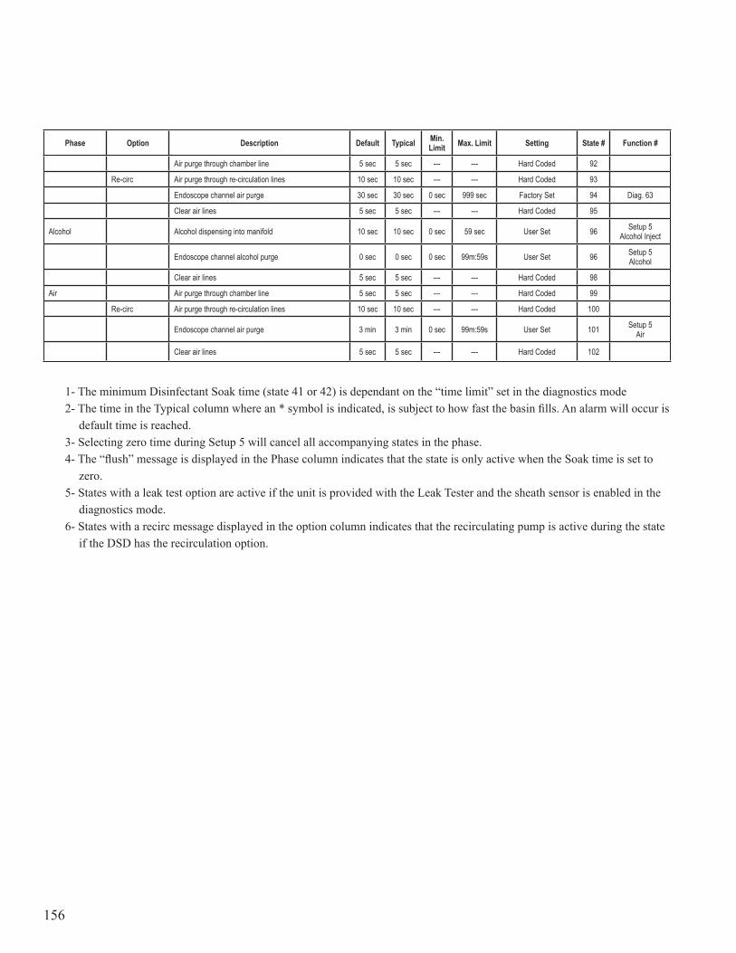
156
Phase Option Description Default Typical Min. Limit Max. Limit Setting State # Function #
Air purge through chamber line 5 sec 5 sec --- --- Hard Coded 92
Re-circ Air purge through re-circulation lines 10 sec 10 sec --- --- Hard Coded 93
Endoscope channel air purge 30 sec 30 sec 0 sec 999 sec Factory Set 94 Diag. 63
Clear air lines 5 sec 5 sec --- --- Hard Coded 95
Alcohol Alcohol dispensing into manifold 10 sec 10 sec 0 sec 59 sec User Set 96 Setup 5 Alcohol Inject
Endoscope channel alcohol purge 0 sec 0 sec 0 sec 99m:59s User Set 96 Setup 5 Alcohol
Clear air lines 5 sec 5 sec --- --- Hard Coded 98
Air Air purge through chamber line 5 sec 5 sec --- --- Hard Coded 99
Re-circ Air purge through re-circulation lines 10 sec 10 sec --- --- Hard Coded 100
Endoscope channel air purge 3 min 3 min 0 sec 99m:59s User Set 101 Setup 5 Air
Clear air lines 5 sec 5 sec --- --- Hard Coded 102
1- The minimum Disinfectant Soak time (state 41 or 42) is dependant on the “time limit” set in the diagnos tics mode2- The time in the Typical column where an * symbol is indicated, is subject to how fast the basin fills. An alarm will occur is
default time is reached.3- Selecting zero time during Setup 5 will cancel all accompanying states in the phase.4- The “flush” message is displayed in the Phase column indicates that the state is only active when the Soak time is set to
zero.5- States with a leak test option are active if the unit is provided with the Leak Tester and the sheath sensor is enabled in the
diagnostics mode.6- States with a recirc message displayed in the option column indicates that the recirculating pump is active during the state
if the DSD has the recirculation option.
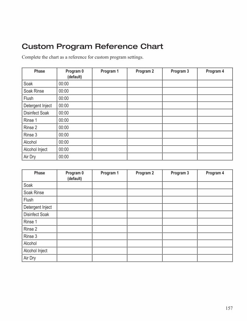
157
Custom Program Reference ChartComplete the chart as a reference for custom program settings.
Phase Program 0 (default)
Program 1 Program 2 Program 3 Program 4
Soak 00:00Soak Rinse 00:00Flush 00:00Detergent Inject 00:00Disinfect Soak 00:00Rinse 1 00:00Rinse 2 00:00Rinse 3 00:00Alcohol 00:00Alcohol Inject 00:00Air Dry 00:00
Phase Program 0 (default)
Program 1 Program 2 Program 3 Program 4
SoakSoak RinseFlushDetergent InjectDisinfect SoakRinse 1Rinse 2Rinse 3AlcoholAlcohol InjectAir Dry
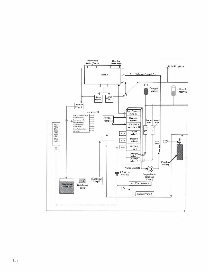
158

159

160
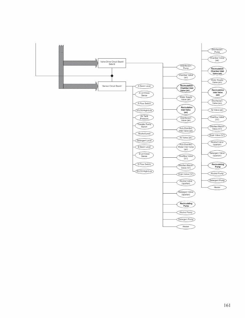
161
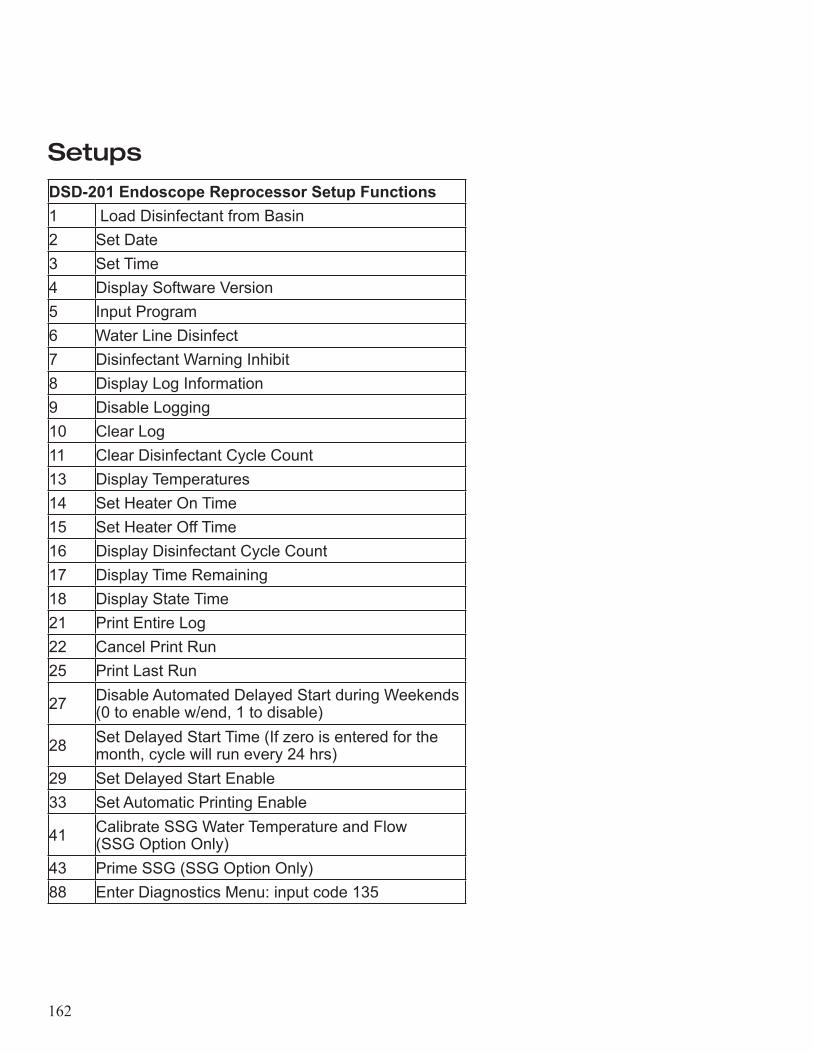
162
Setups
DSD-201 Endoscope Reprocessor Setup Functions 1 Load Disinfectant from Basin 2 Set Date3 Set Time4 Display Software Version5 Input Program 6 Water Line Disinfect7 Disinfectant Warning Inhibit8 Display Log Information9 Disable Logging10 Clear Log11 Clear Disinfectant Cycle Count13 Display Temperatures14 Set Heater On Time15 Set Heater Off Time16 Display Disinfectant Cycle Count17 Display Time Remaining18 Display State Time21 Print Entire Log22 Cancel Print Run25 Print Last Run
27 Disable Automated Delayed Start during Weekends (0 to enable w/end, 1 to disable)
28 Set Delayed Start Time (If zero is entered for the month, cycle will run every 24 hrs)
29 Set Delayed Start Enable33 Set Automatic Printing Enable
41 Calibrate SSG Water Temperature and Flow (SSG Option Only)
43 Prime SSG (SSG Option Only)88 Enter Diagnostics Menu: input code 135

163
Specifications
Chassis Dimensions (height x width x depth)
Height with lid open
46”x36”x21” (117x91x53cm)
64 inches (162.5 cm)
Weight (approx.) 400lbs (181kg)
Power Cord Hospital grade 8 feet (2.4m)
Altitude <15,000 feet (4,572m)
Humidity 20% to 80%, non-condensing
Temperature 80°F ± 20° (27°C ± 10°)
Mains Supply Voltage Fluctuations Not to exceed ±10% of the nominal voltage
Installation Over Voltage Category II
Classification I, Ordinary Protection
Electrical Requirements 230 VAC 50/60 Hz, 6A 1f120 VAC 60 Hz, 12A 1f
Water Requirements Potable water from building (cold water supply). 35-40psi (2.4 - 2.75bar) at regulator. Water temperature maximum: 110°F (43°C)
Rinse Water Consumption Approx. 10 gallons (39 liters) per cycle
Designed for Use Indoor
Environmental Rating Standard
Pollution Degree 2
Mode of Operation Continuous
Degree of Mobility Stationary
Waste Drain
The reprocessors drain is 25 inches (60cm) above the floor. Because the reprocessor uses a gravity system there must be at least a 3 inch (25mm) drop from the reprocessor over 36 inches (30cm) for proper draining.
CapacitiesDisinfectant reservoir: 15 liters Basin: 11 liters Alcohol and detergent reservoir: 800ml each
Disinfectant Compatibilities Contact your local distributor for compatible reprocessing chemicals.
Internal Heater Ambient temperature to 125°F (52°C)
164
Product WarrantyLimited WarrantySubject to the terms below, Medivators Inc. (the “Company”) warrants that its products (the “Products”) will conform to the Company’s written specifications (where applicable) and will be free from defects in material and workmanship under normal use and service for the following periods (the “Warranty Period”):Endoscope reprocessors and associated equipment, and Irrigation Pumps: fifteen (15) months from date of shipment from the Company or one (1) year from the date of installation, whichever occurs first.Consumables, accessories, and Product service parts, including, but not limited to, endoscope hook-ups, filters, printers, printer supplies, test strips, accessory bags, and service parts for products: ninety (90) days from the date of installation or one hundred and twenty (120) days from the date of shipment, whichever occurs first.Disposable Products: warranted for single use. The Warranty Period will not in any case exceed the expiration date on the Product label.The warranty does not cover, and the Company will have no warranty obligation whatsoever with respect to, any damage to a Product caused by or associated with: (i) external causes, including without limitation, accident, vandalism, acts-of-God, power failure or electric power surges, (ii) abuse, misuse or neglect of the Product by the customer or use of unauthorized third party filters or other consumables and accessories, (iii) usage not in accordance with product instructions, (iv) the customer’s failure to perform required preventive maintenance, or (v) servicing or repair not authorized by the Company.Limitation of RemedyThe warranty obligation of the Company hereunder is limited to (at its option) (i) the repair or replacement of the defective Products or any parts it deems defective, or (ii) a refund of the purchase price. This will be customer’s exclusive remedy for a covered defect.In order to recover under the warranty, the customer must notify the Company in the state (if in the U.S.A.) or the country of installation, of the defect (describing the problem in reasonable detail) prior to the expiration of the Warranty Period and within thirty (30) days of discovery of the defect. Upon receiving the Company’s official “Returned Material Authorization” (RMA), the customer must promptly return the defective part or Product to the Company (or the service center indicated on the RMA), freight and insurance prepaid. The Company will not be responsible for any damage during shipment. Warranty DisclaimerTHE WARRANTY ABOVE IS THE COMPANY’S ENTIRE WARRANTY OBLIGATION TO THE PURCHASER OF PRODUCTS. IT IS IN LIEU OF ALL OTHER WARRANTIES OF THE COMPANY, EXPRESS OR IMPLIED, INCLUDING, WITHOUT LIMITATION, WARRANTY OF MERCHANTABILITY OR FITNESS FOR A PARTICULAR PURPOSE, AND THE COMPANY DOES NOT REPRESENT OR WARRANT THAT ANY PRODUCT WILL MEET CUSTOMER’S REQUIREMENTS. THE COMPANY’S RESPONSIBILITY FOR DEFECTS IN A PRODUCT IS LIMITED SOLELY TO REPAIR, REPLACEMENT OR REFUND OF THE PURCHASE PRICE AS SET FORTH IN THIS WARRANTY STATEMENT.
165
TO THE EXTENT PERMITTED BY LAW, THE COMPANY SHALL NOT, UNDER ANY CIRCUMSTANCES, BE LIABLE TO CUSTOMER FOR CONSEQUENTIAL, INCIDENTAL, INDIRECT, PUNITIVE OR SPECIAL DAMAGES OR LOSSES, INCLUDING WITHOUT LIMITATION, DAMAGES ARISING OUT OF OR IN CONNECTION WITH ANY MALFUNCTIONS, DELAYS, LOSS OF PROFIT, INTERRUPTION OF SERVICE, OR LOSS OF BUSINESS OR ANTICIPATORY PROFITS, EVEN IF THE COMPANY HAS BEEN APPRISED OF THE LIKELIHOOD OF SUCH DAMAGES OCCURRING.This Warranty gives the customer of Products specific legal rights, and customers may also have other rights which vary from jurisdiction to jurisdiction.In no event shall the Company’s liability exceed the original purchase price of the covered Product.No representative or agent of the Company has any authority to bind the Company to any other representation or warranty with respect to the Products, and the customer accepts the Products subject to all of the terms above.

166

167

168www.medivators.com
Manufactured in the USA by:
Medivators Inc. 14605 28th Avenue NorthMinneapolis, MN 55447 USAToll Free: +1.800.444.4729
Medivators BVSourethweg 116422PC HeerlenThe NetherlandsTel: +31.45.5.471.471
Cantel Medical Asia/Paci�c Pte. Ltd.1A International Business Park#05-01 Singapore 609933Tel: +65.6227.9698
Cantel Medical Devices (China) Co. Ltd.Unit 804-805, Innov Tower Block A,Hongmei Road, Xuhui 200233 ShanghaiTel: +86 21 60161380Fax: +86 21 61210913