Embed Size (px)
Citation preview
1CER OPTIMA Service Manual
CER OPTIMAEndoscope Reprocessing System
ServiceManual

2 CER OPTIMA Service Manual
50098-027 Rev B 1.20.2014
© 2014 MEDIVATORS Inc.
All rights reserved. This publication is protected by copyright. Copying, disclosure to others, or the use of this publication is prohibited without the express written consent of MEDIVATORS.
MEDIVATORS reserves the right to make changes in the specifications shown herein without notice or obligation. Contact your MEDIVATORS representative or MEDIVATORS customer service for more information.
3CER OPTIMA Service Manual
Table of Contents
Chapter 1 - INTRODUCTIONUsing this Manual .......................................................................................................5
Indications for Use ........................................................................................................... 5Safety ........................................................................................................................6
Intended Use .................................................................................................................... 6 Operator Safety ................................................................................................................ 6Moving the CER OPTIMA.................................................................................................. 6Installation and Maintenance ............................................................................................7Water Quality and Filtration ...............................................................................................8Chemicals ......................................................................................................................... 8Detergent Solution ............................................................................................................8Disinfectant Solution ........................................................................................................ 9
Monitoring Disinfectant Potency ...............................................................................9Endoscope Precleaning and Testing ..........................................................................9Electromagnetic Compatibility .................................................................................10Endoscope Hookups .............................................................................................. 10Cleaning and Disinfection .......................................................................................12Specifications ........................................................................................................ 16
Chapter 2 - PLUMBING AND ELECTRICAL SPECIFICATIONSWater Supply ............................................................................................................17Drain .........................................................................................................................18Electrical Requirements .......................................................................................... 18
Chapter 3 General Machine Layout ........................................................................................ 19
Chapter 4 - SERVICEPower Entry Module ............................................................................................... 23Channel Pump Fuses ............................................................................................. 25
Printer Replacement ......................................................................................... 2724VDC Power Supply Replacement ................................................................. 29Power Supply Replacement Procedure ............................................................ 29Barcode Scanner Replacement ........................................................................ 30CPU Replacement ............................................................................................ 31
Removal Procedure ................................................................................... 32Installation Procedure ................................................................................ 32CPU Jumper Location ............................................................................... 32
Channel Pump .................................................................................................. 34Channel Pump Replacement ..................................................................... 34
Transfer Pump ................................................................................................... 36Transfer Pump Replacement ...................................................................... 36
CER OPTIMA® Alcohol System ......................................................................... 38Perastaltic Pump ........................................................................................ 38
To Access the Pump ......................................................................................... 38Perastaltic Pump Head Housing Replacement ............................................... 39
4 CER OPTIMA Service Manual
Replacing the Alcohol Sensor ........................................................................... 40Changing Disinfectant Type .............................................................................. 41
Disinfectant Options .................................................................................... 41Change the Disinfectant Type ..................................................................... 41
Setting Date & Time .......................................................................................... 42Error & Warning Messages ............................................................................... 44OPTIMA Diagnostics ......................................................................................... 60
Introduction ................................................................................................. 60To Access Diagnostics ................................................................................. 61
Warranty ............................................................................................................ 71
5CER OPTIMA Service Manual
Introduction
Using this ManualThis manual is for the MEDIVATORS CER OPTIMA® automatic endoscope reprocessor which is available in the following models:
• CER-1 OPTIMA, Single endoscope reprocessing capability
• CER-2 OPTIMA, Single or dual endoscope reprocessing capability
This manual covers maintenance and troubleshooting procedures to keep the reprocessor in good operating order.
Throughout the manual are notes, service notes, cautions, and warnings which provide additional important information. An example of each is illustrated below.
Indications for Use
MEDIVATORS CER OPTIMA Endoscope Reprocessing System, washes, disinfects and rinses flexible endoscopes, including fiberoptic, ultra-sound and video endoscopes between patient uses. The CER OPTIMA System is indicated to provide high level disinfection, using RAPICIDE® High-Level Disinfectant, Glutaraldehyde disinfectant or Ortho-phthaladehyde (also known as OPA) disinfectant, for heat sensitive semi-critical endoscopes. Manual cleaning of endoscopes is required prior to placement in the CER OPTIMA system.
Note: A note refers to relevant information not covered in the main body of the text.
Service: A service note refers to operations or repairs only a trained service technician may perform.
Caution! A caution describes actions and conditions that may cause damage to or destruction of the equipment.
Warning! A warning describes actions and conditions that may cause severe personal injury or death to the operator or patient.
!
CHAPTER 1
6 CER OPTIMA Service Manual
Safety
This section outlines general safety guidelines for proper operation and service of the reprocessor. Failure to follow these guidelines may result in severe injury or death to the patient and/or operator. Read and understand all operating and service procedures before attempting to operate the reprocessor. If the equipment is not used as specified, the ability of the equipment to high level disinfect an endoscope may be at risk. Contact your MEDIVATORS representative if you have any questions regarding the safe and correct way to operate and service this equipment.
Intended Use Only properly trained individuals may operate or service the reprocessor. Never use the reprocessor for any purpose other than the manufacturer’s specific indications for use. It is the responsibility of the facility to maintain and ensure that adequate training is provided to operators. It is recommended that the facility conduct regular training of all personnel concerned with the operation and maintenance of this equipment, including emergency procedures for safe handling of an accidental chemical spill. Attendance records of the training should be maintained and evidence of understanding demonstrated.
Operator Safety Avoid biological contamination and chemical burns–always wear appropriate personal protective equipment when handling endoscopes or disinfectant solutions. Never open the reprocessor lid during operation.
Moving the CER OPTIMABefore moving the CER OPTIMA®, ensure the electrical cord, disinfectant tubing, drain line and water supply line are either disconnected or are appropriate lengths to accommodate the relocation of the machine. Failure to do so may result in damage to the machine. While moving the CER OPTIMA, ensure the machine remains in an upright position. Moving or resting the machine in any orientation other than an upright position may result in damage to the machine. Take precautions to ensure the machine does not tip over which could result in damage to the machine or personal injury. The machine may be placed upon a mobile cart or dolly. When loading or unloading the machine onto or off of a cart or dolly, utilize appropriate lifting equipment or manpower to avoid damage to the machine or personal injury.
Note: To avoid injury or death from an electrical insulation breakdown within the unit, the GFI (ground fault interrupter) circuit breaker should be checked for proper operation on an annual basis.
Note: If during the use of this equipment you see or smell smoke, immediately disconnect the unit from the power supply, discontinue use and call MEDIVATORS Technical Support at 1-800-444-4729.
7CER OPTIMA Service Manual
Note: Prior to undertaking any service or maintenance operation, or when resetting the GFI ensure that the CER OPTIMA® is disconnected from the main power supply. If service or maintenance operations are to be conducted on the water system, ensure that the CER OPTIMA is isolated from the main water supply.
Warning! The reprocessor must be protectively grounded.
Installation and Maintenance For complete system installation instructions and details, refer to the:
• CER OPTIMA Pre-site Installation Instructions• CER OPTIMA Water Filtration Installation Instructions• CER OPTIMA Installation Instructions
Upon installation, position the equipment so the power on/off switch is readily accessible by the operator. Ensure compliance with the installation documents before operating the system.
• The reprocessor must be properly grounded. • The disinfectant immersion period (contact time) is fixed in the CER OPTIMA’s software,
specific to the high level disinfectant that is displayed on the screen at the start of the cycle. • All pressure regulators are factory-preset. Do not adjust the settings. Contact MEDIVATORS
Technical Support for assistance. • Do not use alcohol or alcohol-based products to clean the reprocessor cabinet. • The hook-ups are not autoclavable and must be reprocessed by low temperature disinfection only. • Replacement parts must be ordered from the manufacturer to maintain the warranty. • Regularly inspect reprocessor for basin damage, pipe and tubing damage, which may result in
leaks.• Ensure CER OPTIMA unit is level prior to operation. Place a bubble level on the front and side
edges of the basin. Level the unit using the four (4) adjustable feet on the bottom of the reprocessor. To adjust the level of the reprocessor, rotate the foot clockwise to raise up, or counterclockwise to lower the corner. When the basin is full of liquid, the level of the liquid should be even around the top of the basin.
Proper maintenance will ensure effective disinfection and prolong the life of the reprocessor.
8 CER OPTIMA Service Manual
Water Quality and Filtration Potable water is the minimum standard. Incoming water must be pre-filtered to a minimum of 1 micron. Use a cold water line with a pressure of 40 to 60 PSI that will supply a flow rate of 2.5 to 3 GPM (9.4 LPM to 11.4 LPM) to the water filtration system. The cold water supply should not exceed 104°F (40°C).
• The high performance 0.2-micron absolute water filter included with the reprocessor is a bacterial-retentive filter. This filter removes all microorganisms and particles greater than 0.2-micron.
• The routine maintenance schedule recommends replacing the 0.2-micron water filter every 6 months or sooner, depending on the pre-filtration system and the quality of the incoming water. Never use a nominal 0.2 micron water filter.
• Incoming water supplied (upstream of the external pre-filtration system) should be shut-off at the end of every work day. Ensure this water supply is turned on prior to operating the reprocessor.
• The pre-filtration system should be monitored for excessive pressure drop indicating blocked filter membranes. If this occurs replace the water filter.
Chemicals The CER OPTIMA® is designed for use with RAPICIDE® High-Level Disinfectant, Glutaraldehyde disinfectant, or Ortho-phthaladehyde (also known as OPA) disinfectant. Refer to the American National Standard recommended practice titled, Chemical Sterilants and High Level Disinfectants: A guide to Selection and Use (AAMI TIR7:1999) and/or Safe Handling and Biological Decontamination of Reusable Medical Devices in Health Care Facilities and in Nonclinical Settings (AAMI/ANSI ST35:2003). These documents are available from the Association for the Advancement of Medical Instrumentation.The CER OPTIMA also allows the use of detergents for endoscope washing, or 70% Ethyl Alcohol and Isopropyl Alcohol for end-of-cycle endoscope drying.For all chemicals used within the CER OPTIMA, refer to the respective chemical labeling, directions-for-use (DFU) and/or material safety data sheet (MSDS) for chemistry constituents, as well as for safety and handling guidelines. These documents should be displayed and stored near the CER OPTIMA for easy access in the event of a chemical spill or emergency resulting in contact with any chemical that is considered hazardous.In case of an emergency in which eye or skin contact, or inhalation occurs, such as release of toxic or pathogenic material, or leakage from a disinfectant container, or detergent (alkaline, acidic, non-enymatic or enzymatic) container, always refer to the manufacturer’s labeling, directions for use and/or Materials Safety Data Sheet (MSDS), for first aid measures, accidental release measures and exposure controls/personal protection. Call the emergency telephone number located on the MSDS if additional manufacturer’s information is needed.
Detergent Solution If the user decides to incorporate a pre-wash in the reprocessing cycle, MEDIVATORS recommends the use of a medical-grade detergent solution which is bacteriostatic, low foaming, free-rinsing and having a neutral pH.
9CER OPTIMA Service Manual
Caution! Never use household detergent in the reprocessor.
Disinfectant Solution The CER OPTIMA® is designed for use with RAPICIDE® High-Level Disinfectant (HLD), Glutaraldehyde HLD, or Ortho-phthaladehyde (also known as OPA) HLD.MEDIVATORS only recommends the use of the HLD that is legally marketed and FDA cleared as a high-level disinfectant/sterilant for use on flexible endoscopes and medical devices/instruments. Refer to the FDA website to confirm the HLD is cleared for use.It is the user’s responsibility to ensure the HLD is used per the disinfectant manufacturer’s instructions, including the proper contact time, use temperature, and post rinses. Refer to the high level disinfectant manufacturer’s directions for use for further instructions. Monitoring Disinfectant Potency High Level Disinfectant (HLD) testing must be performed before each reprocessing cycle. The minimum required concentration (MRC) testing of the high level disinfectant (HLD), ensures the HLD is at an effective level of potency, so that it can be used to disinfect an endoscope or medical device. Testing the potency prior to starting a reprocessing cycle, confirms the disinfectant’s MRC potency, and that it can be used to achieve high level disinfection of an endoscope or medical device.
Use only the disinfectant manufacturer’s recommended test strips to test the potency of the HLD. If the high level disinfectant is below the minimum required concentration, then discard the used disinfectant and replace it with new disinfectant, prior to initiating a reprocessing cycle. Refer to the test strip manufacturer’s instructions, for further details and step-by-step use instructions.
Endoscope Precleaning and Testing All endoscopes must be manually precleaned prior to disinfection. Follow the endoscope manufacturer’s instructions and established professional guidelines to properly preclean the endoscope.
• Endoscopes with elevator wire channels require additional manual cleaning and disinfection steps.
• Leak test endoscopes prior to disinfection procedures.
!
10 CER OPTIMA Service Manual
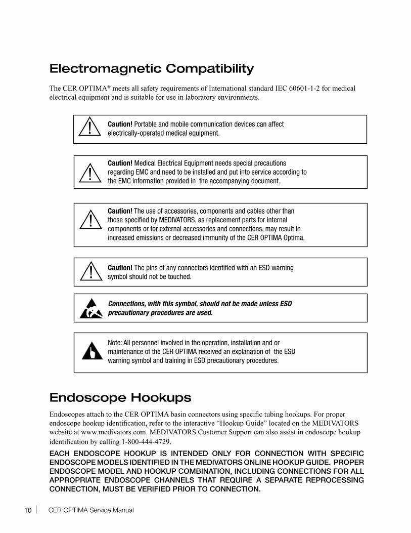
Electromagnetic Compatibility The CER OPTIMA® meets all safety requirements of International standard IEC 60601-1-2 for medical electrical equipment and is suitable for use in laboratory environments.
Caution! Portable and mobile communication devices can affect electrically-operated medical equipment.
Caution! Medical Electrical Equipment needs special precautions regarding EMC and need to be installed and put into service according to the EMC information provided in the accompanying document.
Caution! The use of accessories, components and cables other than those specified by MEDIVATORS, as replacement parts for internal components or for external accessories and connections, may result in increased emissions or decreased immunity of the CER OPTIMA Optima.
Caution! The pins of any connectors identified with an ESD warning symbol should not be touched.
Connections, with this symbol, should not be made unless ESD precautionary procedures are used.
Note: All personnel involved in the operation, installation and or maintenance of the CER OPTIMA received an explanation of the ESD warning symbol and training in ESD precautionary procedures.
Endoscope Hookups
Endoscopes attach to the CER OPTIMA basin connectors using specific tubing hookups. For proper endoscope hookup identification, refer to the interactive “Hookup Guide” located on the MEDIVATORS website at www.medivators.com. MEDIVATORS Customer Support can also assist in endoscope hookup identification by calling 1-800-444-4729.EACH ENDOSCOPE HOOKUP IS INTENDED ONLY FOR CONNECTION WITH SPECIFIC ENDOSCOPE MODELS IDENTIFIED IN THE MEDIVATORS ONLINE HOOKUP GUIDE. PROPER ENDOSCOPE MODEL AND HOOKUP COMBINATION, INCLUDING CONNECTIONS FOR ALL APPROPRIATE ENDOSCOPE CHANNELS THAT REQUIRE A SEPARATE REPROCESSING CONNECTION, MUST BE VERIFIED PRIOR TO CONNECTION.
!
!
!
!
11CER OPTIMA Service Manual
The online hookup guide is available at: http://www.medivators.com/HookupLookup.Refer to the online hookup guide for additional notes and considerations specific to individual endoscope models.
• Endoscopes must be thoroughly cleaned according to the manufacturer’s instructions and established professional society guidelines prior to hookup connection. Failure to properly clean and prepare endoscopes may result in inadequate high level disinfection and/or damage to the endoscope.
• Endoscopes must be inspected for damage and verified to be in proper working order prior to hookup connection. If cleaning or leak testing identifies endoscope damage or channels that may be restricted or obstructed, the endoscope should be repaired before further reprocessing. Connection of hookups to damaged endoscopes, or endoscopes with restricted or obstructed channels may result in inadequate high level disinfection.
• Users operating MEDIVATORS AERs and hookups must be trained and competent in the understanding of endoscope channel systems. Prior to hookup connection, users must verify that the hookup used contains connections for all appropriate endoscope channels that require a separate reprocessing connection.
• Ensure proper alignment of all connectors with the endoscope mating parts prior to attachment. Misalignment may cause damage to hookup components and/or mating parts.
• All connectors and adapters must remain firmly attached and unrestricted for the entire disinfection cycle to ensure adequate high level disinfection. Users must inspect the endoscope and hookup combination to verify proper connection and flow.
• Remove connectors from mating parts by gripping the connector directly and detaching from the endoscope. Do not remove connectors by pulling on tubing.
• Hookups must be periodically checked to ensure their functionality is not impaired. Hookups should be inspected for damaged or worn connectors, missing components, kinked/blocked tubing or other signs of deterioration. If signs of damage or deterioration are found, the hookup should be replaced.
• Modifications or repairs to hookups which do not correspond to the manufacturer’s specifications may result in inadequate high level disinfection and/or damage to endoscopes.
• Leak testing should be carried out in accordance with endoscope manufacturer’s recommendations prior to hookup connection.
• Install all necessary waterproof caps, plugs and cleaning adapters prior to immersion.• Do NOT autoclave MEDIVATORS hookups.• Avoid biological contamination. Always wear personal protective equipment when handling
endoscopes. MEDIVATORS makes no claim of high-level disinfection efficacy when these instructions are not followed, or when this hookup is used with endoscopes other than those specified in the online hookup guide.
12 CER OPTIMA Service Manual
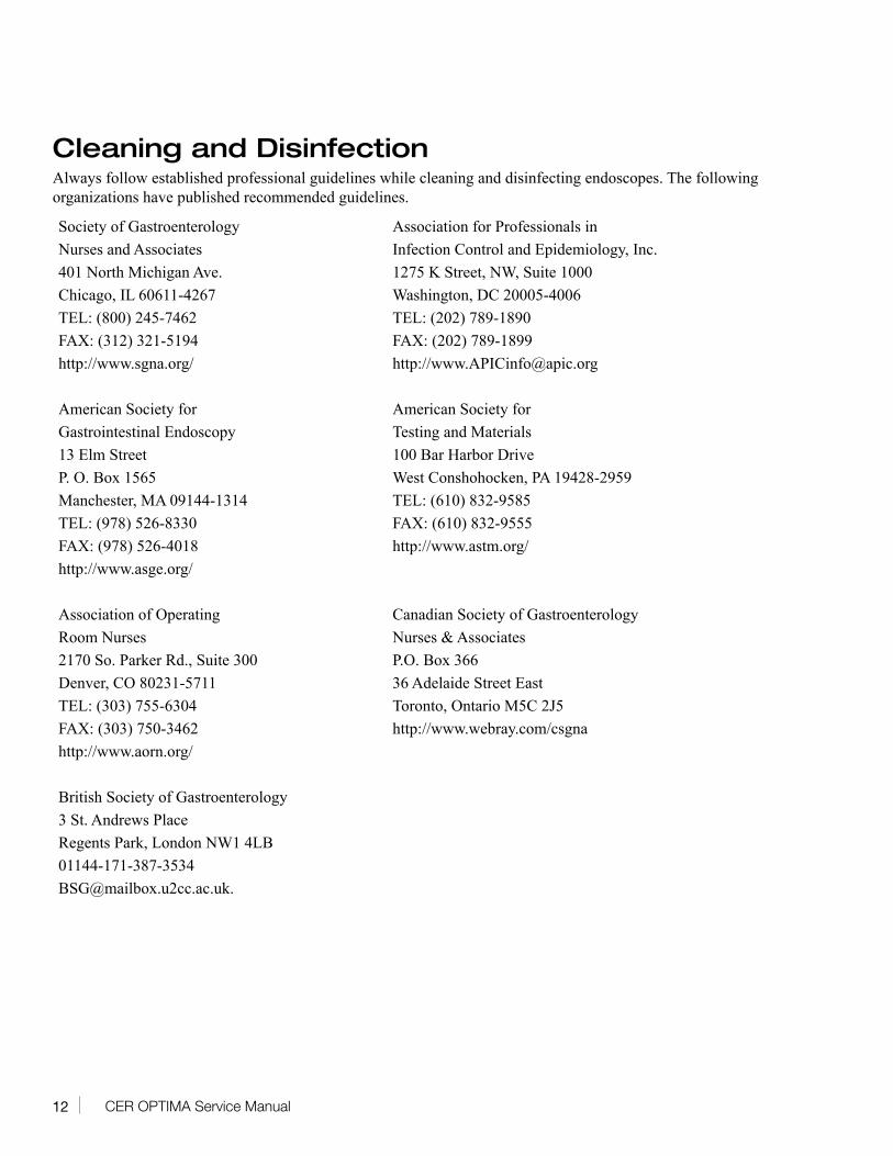
Cleaning and Disinfection Always follow established professional guidelines while cleaning and disinfecting endoscopes. The following organizations have published recommended guidelines.
Society of Gastroenterology Association for Professionals in Nurses and Associates Infection Control and Epidemiology, Inc. 401 North Michigan Ave. 1275 K Street, NW, Suite 1000 Chicago, IL 60611-4267 Washington, DC 20005-4006 TEL: (800) 245-7462 TEL: (202) 789-1890 FAX: (312) 321-5194 FAX: (202) 789-1899 http://www.sgna.org/ http://[email protected]
American Society for American Society for Gastrointestinal Endoscopy Testing and Materials 13 Elm Street 100 Bar Harbor Drive P. O. Box 1565 West Conshohocken, PA 19428-2959 Manchester, MA 09144-1314 TEL: (610) 832-9585 TEL: (978) 526-8330 FAX: (610) 832-9555 FAX: (978) 526-4018 http://www.astm.org/ http://www.asge.org/
Association of Operating Canadian Society of Gastroenterology Room Nurses Nurses & Associates 2170 So. Parker Rd., Suite 300 P.O. Box 366 Denver, CO 80231-5711 36 Adelaide Street East TEL: (303) 755-6304 Toronto, Ontario M5C 2J5 FAX: (303) 750-3462 http://www.webray.com/csgna http://www.aorn.org/
British Society of Gastroenterology 3 St. Andrews Place Regents Park, London NW1 4LB 01144-171-387-3534 [email protected].
13CER OPTIMA Service Manual
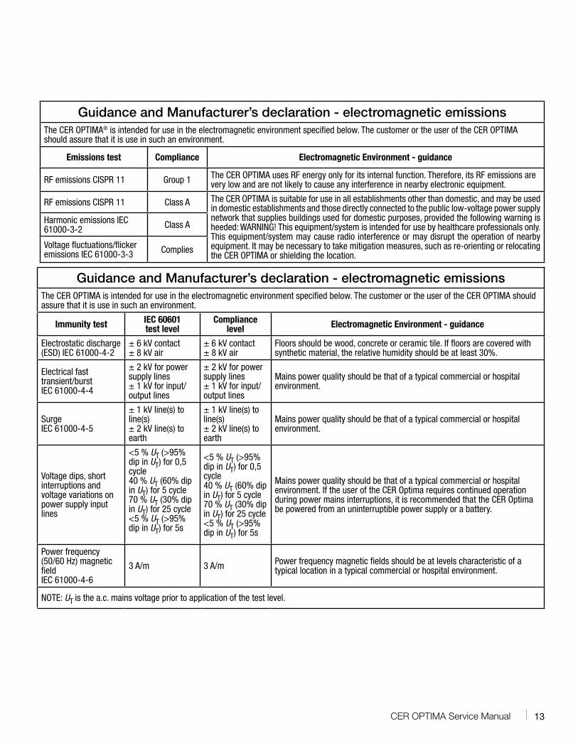
Guidance and Manufacturer’s declaration - electromagnetic emissionsThe CER OPTIMA® is intended for use in the electromagnetic environment specified below. The customer or the user of the CER OPTIMA should assure that it is use in such an environment.
Emissions test Compliance Electromagnetic Environment - guidance
RF emissions CISPR 11 Group 1 The CER OPTIMA uses RF energy only for its internal function. Therefore, its RF emissions are very low and are not likely to cause any interference in nearby electronic equipment.
RF emissions CISPR 11 Class A The CER OPTIMA is suitable for use in all establishments other than domestic, and may be used in domestic establishments and those directly connected to the public low-voltage power supply network that supplies buildings used for domestic purposes, provided the following warning is heeded: WARNING! This equipment/system is intended for use by healthcare professionals only. This equipment/system may cause radio interference or may disrupt the operation of nearby equipment. It may be necessary to take mitigation measures, such as re-orienting or relocating the CER OPTIMA or shielding the location.
Harmonic emissions IEC 61000-3-2 Class A
Voltage fluctuations/flicker emissions IEC 61000-3-3 Complies
Guidance and Manufacturer’s declaration - electromagnetic emissionsThe CER OPTIMA is intended for use in the electromagnetic environment specified below. The customer or the user of the CER OPTIMA should assure that it is use in such an environment.
Immunity test IEC 60601 test level
Compliance level Electromagnetic Environment - guidance
Electrostatic discharge (ESD) IEC 61000-4-2
± 6 kV contact ± 8 kV air
± 6 kV contact ± 8 kV air
Floors should be wood, concrete or ceramic tile. If floors are covered with synthetic material, the relative humidity should be at least 30%.
Electrical fast transient/burstIEC 61000-4-4
± 2 kV for power supply lines ± 1 kV for input/output lines
± 2 kV for power supply lines ± 1 kV for input/output lines
Mains power quality should be that of a typical commercial or hospital environment.
Surge IEC 61000-4-5
± 1 kV line(s) to line(s) ± 2 kV line(s) to earth
± 1 kV line(s) to line(s) ± 2 kV line(s) to earth
Mains power quality should be that of a typical commercial or hospital environment.
Voltage dips, short interruptions and voltage variations on power supply input lines
<5 % UT (>95% dip in UT) for 0,5 cycle40 % UT (60% dip in UT) for 5 cycle70 % UT (30% dip in UT) for 25 cycle<5 % UT (>95% dip in UT) for 5s
<5 % UT (>95% dip in UT) for 0,5 cycle40 % UT (60% dip in UT) for 5 cycle70 % UT (30% dip in UT) for 25 cycle<5 % UT (>95% dip in UT) for 5s
Mains power quality should be that of a typical commercial or hospital environment. If the user of the CER Optima requires continued operation during power mains interruptions, it is recommended that the CER Optima be powered from an uninterruptible power supply or a battery.
Power frequency (50/60 Hz) magnetic field IEC 61000-4-6
3 A/m 3 A/m Power frequency magnetic fields should be at levels characteristic of a typical location in a typical commercial or hospital environment.
NOTE: UT is the a.c. mains voltage prior to application of the test level.
14 CER OPTIMA Service Manual
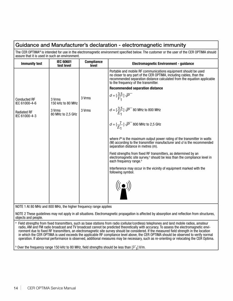
Guidance and Manufacturer’s declaration - electromagnetic immunityThe CER OPTIMA® is intended for use in the electromagnetic environment specified below. The customer or the user of the CER OPTIMA should assure that it is used in such an environment.
Immunity test IEC 60601 test level
Compliance level Electromagnetic Environment - guidance
Conducted RFIEC 61000-4-6
Radiated RFIEC 61000-4-3
3 Vrms150 kHz to 80 MHz
3 Vrms80 MHz to 2,5 GHz
3 Vrms
3 Vrms
Portable and mobile RF communications equipment should be used no closer to any part of the CER OPTIMA, including cables, than the recommended separation distance calculated from the equation applicable to the frequency of the transmitter.
Recommended separation distance
d = [ 3,5 ] √P
d = [ 3,5 ] √P 80 MHz to 800 MHz
d = [ 7 ] √P 800 MHz to 2,5 GHz
where P is the maximum output power rating of the transmitter in watts (W) according to the transmitter manufacturer and d is the recommended separation distance in metres (m).
Field strengths from fixed RF transmitters, as determined by an electromagnetic site survey,a should be less than the compliance level in each frequency range.b
Interference may occur in the vicinity of equipment marked with the following symbol.
NOTE 1 At 80 MHz and 800 MHz, the higher frequency range applies
NOTE 2 These guidelines may not apply in all situations. Electromagnetic propagation is affected by absorption and reflection from structures, objects and people.a Field strengths from fixed transmitters, such as base stations from radio (cellular/cordless) telephones and land mobile radios, amateur
radio, AM and FM radio broadcast and TV broadcast cannot be predicted theoretically with accuracy. To assess the electromagnetic envi-ronment due to fixed RF transmitters, an electromagnetic site survey should be considered. If the measured field strength in the location in which the CER OPTIMA is used exceeds the applicable RF compliance level above, the CER OPTIMA should be observed to verify normal operation. If abnormal performance is observed, additional measures may be necessary, such as re-orienting or relocating the CER Optima.
b Over the frequency range 150 kHz to 80 MHz, field strengths should be less than [V1] V/m.
V1
E1
E1
15CER OPTIMA Service Manual
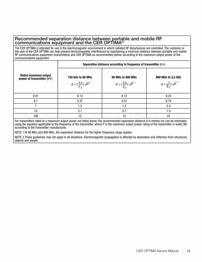
Recommended separation distance between portable and mobile RF communications equipment and the CER OPTIMA®
The CER OPTIMA is intended for use in the electromagnetic environment in which radiated RF disturbances are controlled. The customer or the user of the CER OPTIMA can help prevent electromagnetic interference by maintaining a minimum distance between portable and mobile RF communications equipment (transmitters) and CER OPTIMA as recommended below, according to the maximum output power of the communications equipment.
Rated maximum output power of transmitter (W)
Separation distance according to frequency of transmitter (m)
150 kHz to 80 MHz
d = [ 3,5 ] √P
80 MHz to 800 MHz
d = [ 3,5 ] √P
800 MHz to 2,5 GHz
d = [ 7 ] √P
0,01 0.12 0.12 0.23
0,1 0.37 0.37 0.74
1 1.2 1.2 2.3
10 3.7 3.7 7.4
100 12 12 23
For transmitters rated at a maximum output power not listed above, the recommended separation distance d in metres (m) can be estimated using the equation applicable to the frequency of the transmitter, where P is the maximum output power rating of the transmitter in watts (W) according to the transmitter manufacturer.
NOTE 1 At 80 MHz and 800 MHz, the separation distance for the higher frequency range applies.
NOTE 2 These guidelines may not apply in all situations. Electromagnetic propagation is affected by absorption and reflection from structures, objects and people.
V1 E1 E1
16 CER OPTIMA Service Manual
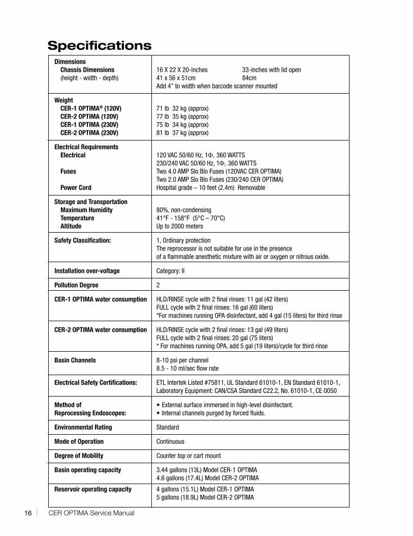
SpecificationsDimensions
Chassis Dimensions 16 X 22 X 20-inches 33-inches with lid open(height - width - depth) 41 x 56 x 51cm 84cm Add 4” to width when barcode scanner mounted
WeightCER-1 OPTIMA® (120V) 71 lb 32 kg (approx)CER-2 OPTIMA (120V) 77 lb 35 kg (approx) CER-1 OPTIMA (230V) 75 lb 34 kg (approx) CER-2 OPTIMA (230V) 81 lb 37 kg (approx)
Electrical RequirementsElectrical 120 VAC 50/60 Hz, 1Φ, 360 WATTS 230/240 VAC 50/60 Hz, 1Φ, 360 WATTSFuses Two 4.0 AMP Slo Blo Fuses (120VAC CER OPTIMA) Two 2.0 AMP Slo Blo Fuses (230/240 CER OPTIMA)Power Cord Hospital grade – 10 feet (2.4m) Removable
Storage and TransportationMaximum Humidity 80%, non-condensingTemperature 41°F - 158°F (5°C – 70°C)Altitude Up to 2000 meters
Safety Classification: 1, Ordinary protection The reprocessor is not suitable for use in the presence of a flammable anesthetic mixture with air or oxygen or nitrous oxide.
Installation over-voltage Category: II
Pollution Degree 2
CER-1 OPTIMA water consumption HLD/RINSE cycle with 2 final rinses: 11 gal (42 liters) FULL cycle with 2 final rinses: 16 gal (60 liters) *For machines running OPA disinfectant, add 4 gal (15 liters) for third rinse
CER-2 OPTIMA water consumption HLD/RINSE cycle with 2 final rinses: 13 gal (49 liters) FULL cycle with 2 final rinses: 20 gal (75 liters) * For machines running OPA, add 5 gal (19 liters)/cycle for third rinse
Basin Channels 8-10 psi per channel 8.5 - 10 ml/sec flow rate
Electrical Safety Certifications: ETL Intertek Listed #75811, UL Standard 61010-1, EN Standard 61010-1, Laboratory Equipment: CAN/CSA Standard C22.2, No. 61010-1, CE 0050
Method of • External surface immersed in high-level disinfectant.Reprocessing Endoscopes: • Internal channels purged by forced fluids.
Environmental Rating Standard
Mode of Operation Continuous
Degree of Mobility Counter top or cart mount
Basin operating capacity 3.44 gallons (13L) Model CER-1 OPTIMA 4.6 gallons (17.4L) Model CER-2 OPTIMA
Reservoir operating capacity 4 gallons (15.1L) Model CER-1 OPTIMA 5 gallons (18.9L) Model CER-2 OPTIMA
17CER OPTIMA Service Manual
Plumbing & Electrical Specifications
Reference the “CER OPTIMA® Pre-site Installation Instructions” the “CER OPTIMA Installation Instructions” and the “CER OPTIMA Water Filtration Installation Instructions” for further CER OPTIMA Installation details.
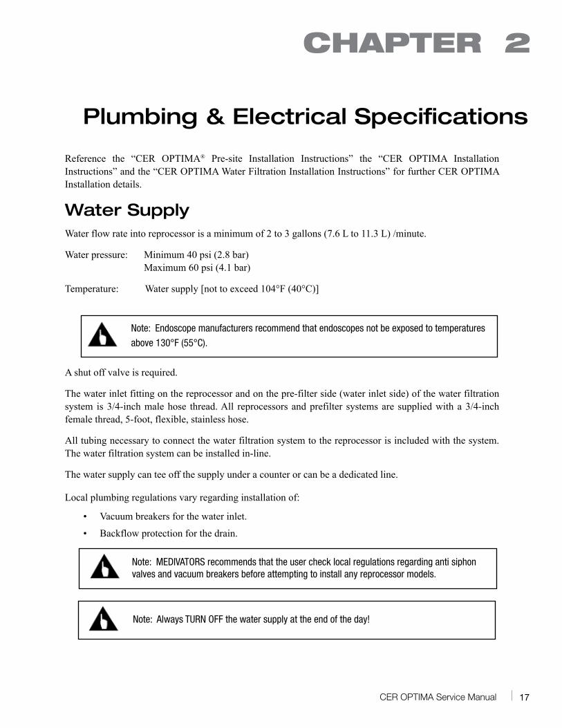
Water SupplyWater flow rate into reprocessor is a minimum of 2 to 3 gallons (7.6 L to 11.3 L) /minute.
Water pressure: Minimum 40 psi (2.8 bar) Maximum 60 psi (4.1 bar)
Temperature: Water supply [not to exceed 104°F (40°C)]
Note: Endoscope manufacturers recommend that endoscopes not be exposed to temperatures
above 130°F (55°C).
A shut off valve is required.
The water inlet fitting on the reprocessor and on the pre-filter side (water inlet side) of the water filtration system is 3/4-inch male hose thread. All reprocessors and prefilter systems are supplied with a 3/4-inch female thread, 5-foot, flexible, stainless hose.
All tubing necessary to connect the water filtration system to the reprocessor is included with the system. The water filtration system can be installed in-line.
The water supply can tee off the supply under a counter or can be a dedicated line.
Local plumbing regulations vary regarding installation of:
• Vacuum breakers for the water inlet.
• Backflow protection for the drain.
Note: MEDIVATORS recommends that the user check local regulations regarding anti siphon valves and vacuum breakers before attempting to install any reprocessor models.
Note: Always TURN OFF the water supply at the end of the day!
CHAPTER 2
18 CER OPTIMA Service Manual
DrainA facility drain pipe having a minimum 1-1/2 inch diameter must be placed at least 1 foot below the CER OPTIMA® drain fitting to ensure complete draining of fluids from the system.
The drain fitting on the reprocessor is 1 1/4-inch OD with ¾-inch ID pipe thread. It is recommended that the reprocessor be installed with the 4-foot flexible drain hose supplied with each reprocessor. The drain pipe must contain an air gap at the point where the CER drain tubing enters it.
The facility drain must be capable of handling a discharge rate of 5 gallons per minute (19L per minute). A facility drain having a dishwasher type drain Y is not an acceptable drain method and cannot be used. The drain Y does not provide adequate drain flow rates and must not be used.
Consult with local plumbing regulations for information regarding backflow protection for drain.
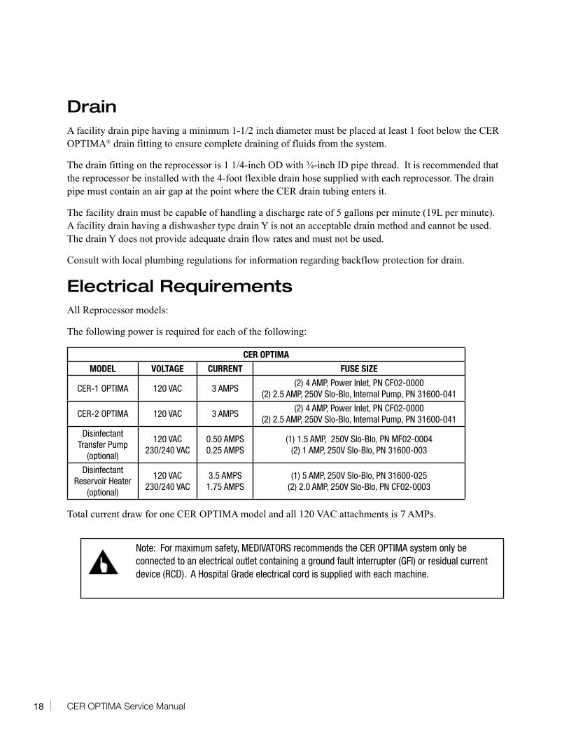
Electrical RequirementsAll Reprocessor models:
The following power is required for each of the following:
CER OPTIMA
MODEL VOLTAGE CURRENT FUSE SIZE
CER-1 OPTIMA 120 VAC 3 AMPS(2) 4 AMP, Power Inlet, PN CF02-0000
(2) 2.5 AMP, 250V Slo-Blo, Internal Pump, PN 31600-041
CER-2 OPTIMA 120 VAC 3 AMPS(2) 4 AMP, Power Inlet, PN CF02-0000
(2) 2.5 AMP, 250V Slo-Blo, Internal Pump, PN 31600-041
Disinfectant Transfer Pump
(optional)
120 VAC 230/240 VAC
0.50 AMPS 0.25 AMPS
(1) 1.5 AMP, 250V Slo-Blo, PN MF02-0004 (2) 1 AMP, 250V Slo-Blo, PN 31600-003
Disinfectant Reservoir Heater
(optional)
120 VAC 230/240 VAC
3.5 AMPS 1.75 AMPS
(1) 5 AMP, 250V Slo-Blo, PN 31600-025 (2) 2.0 AMP, 250V Slo-Blo, PN CF02-0003
Total current draw for one CER OPTIMA model and all 120 VAC attachments is 7 AMPs.
Note: For maximum safety, MEDIVATORS recommends the CER OPTIMA system only be connected to an electrical outlet containing a ground fault interrupter (GFI) or residual current device (RCD). A Hospital Grade electrical cord is supplied with each machine.
19CER OPTIMA Service Manual
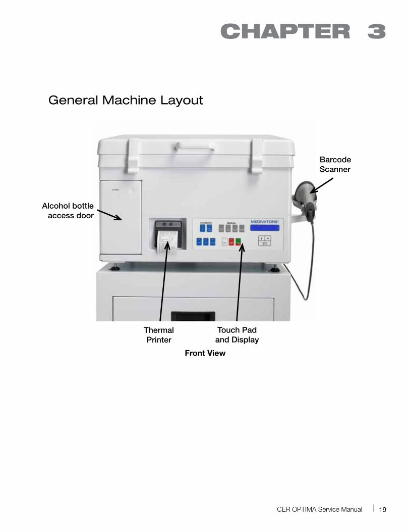
General Machine Layout
Front View
CHAPTER 3
Alcohol bottle access door
ThermalPrinter
Touch Pad and Display
BarcodeScanner
20 CER OPTIMA Service Manual
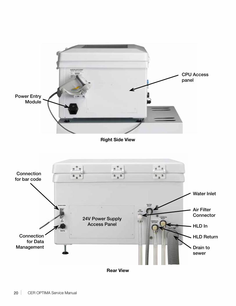
Right Side View
Rear View
Power Entry Module
CPU Access panel
Connection for bar code
Connection for Data
Management
Water Inlet
Air Filter Connector
HLD In
HLD Return
Drain to sewer
24V Power Supply Access Panel
21CER OPTIMA Service Manual
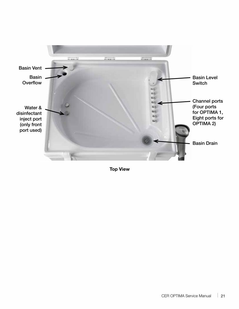
Top View
Basin Vent
Basin Overflow
Water & disinfectant
inject port (only front port used)
Basin Level Switch
Channel ports (Four ports for OPTIMA 1, Eight ports for OPTIMA 2)
Basin Drain

22 CER OPTIMA Service Manual
23CER OPTIMA Service Manual
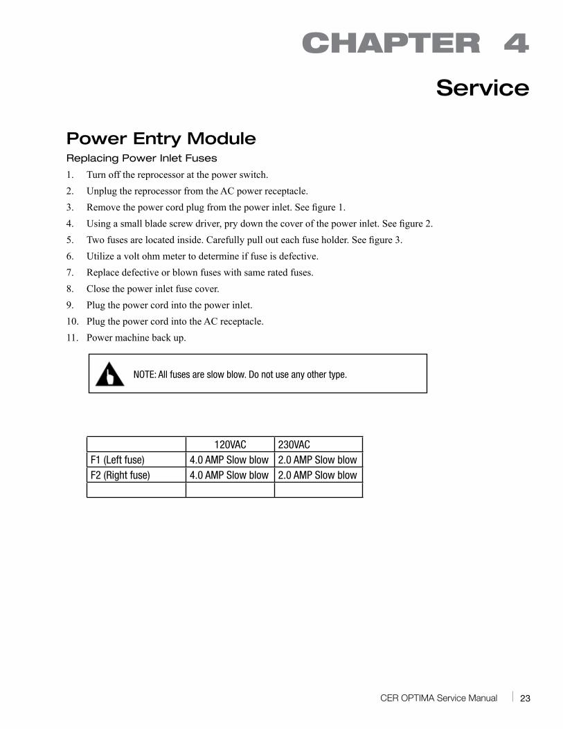
Power Entry ModuleReplacing Power Inlet Fuses
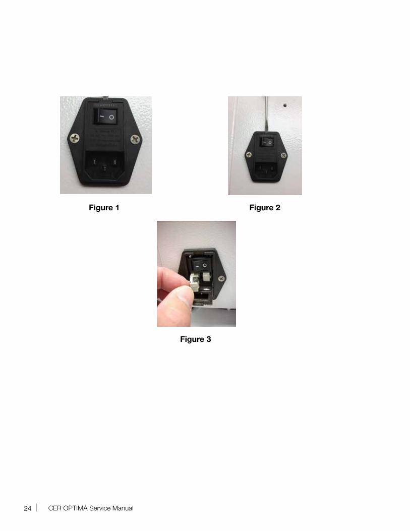
1. Turn off the reprocessor at the power switch.2. Unplug the reprocessor from the AC power receptacle.3. Remove the power cord plug from the power inlet. See figure 1.4. Using a small blade screw driver, pry down the cover of the power inlet. See figure 2.5. Two fuses are located inside. Carefully pull out each fuse holder. See figure 3.6. Utilize a volt ohm meter to determine if fuse is defective.7. Replace defective or blown fuses with same rated fuses.8. Close the power inlet fuse cover.9. Plug the power cord into the power inlet.10. Plug the power cord into the AC receptacle.11. Power machine back up.
NOTE: All fuses are slow blow. Do not use any other type.
120VAC 230VAC
F1 (Left fuse) 4.0 AMP Slow blow 2.0 AMP Slow blowF2 (Right fuse) 4.0 AMP Slow blow 2.0 AMP Slow blow
CHAPTER 4
Service
24 CER OPTIMA Service Manual
Figure 1 Figure 2
Figure 3
25CER OPTIMA Service Manual
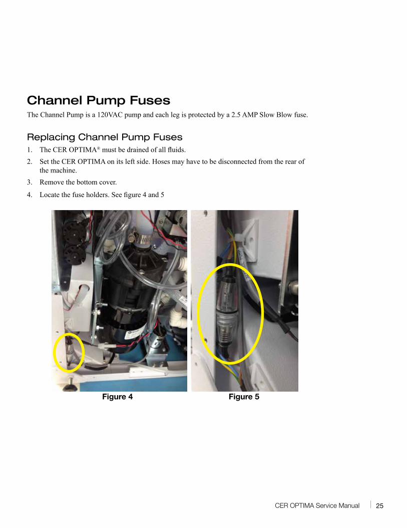
Channel Pump FusesThe Channel Pump is a 120VAC pump and each leg is protected by a 2.5 AMP Slow Blow fuse.
Replacing Channel Pump Fuses1. The CER OPTIMA® must be drained of all fluids.2. Set the CER OPTIMA on its left side. Hoses may have to be disconnected from the rear of
the machine.3. Remove the bottom cover.
4. Locate the fuse holders. See figure 4 and 5
Figure 4 Figure 5
26 CER OPTIMA Service Manual
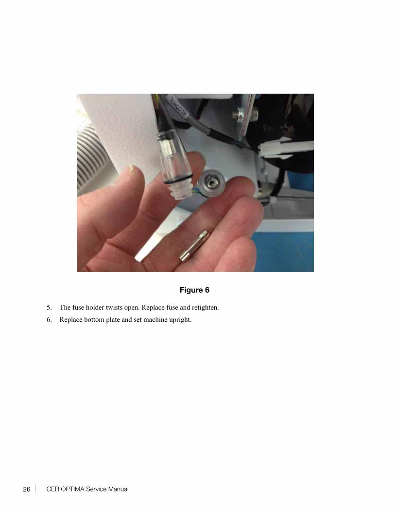
Figure 6
5. The fuse holder twists open. Replace fuse and retighten.
6. Replace bottom plate and set machine upright.
27CER OPTIMA Service Manual
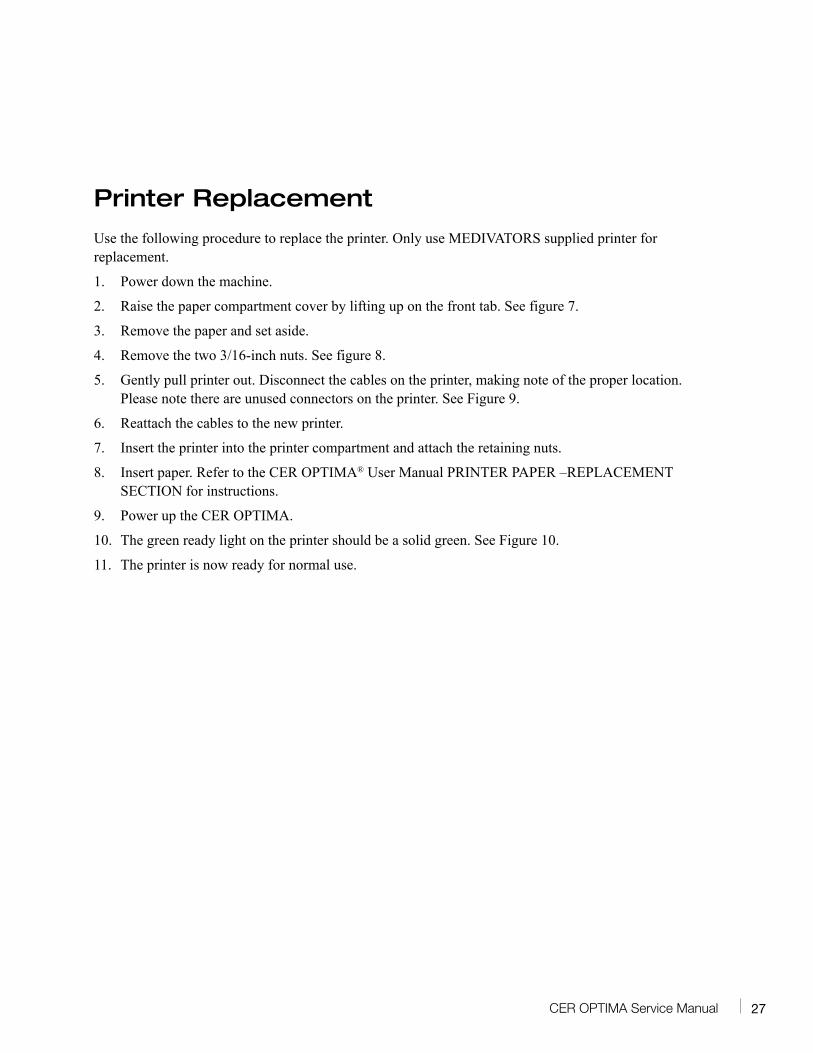
Printer Replacement
Use the following procedure to replace the printer. Only use MEDIVATORS supplied printer for replacement.
1. Power down the machine.
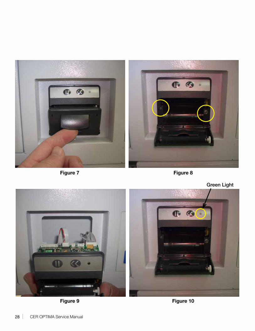
2. Raise the paper compartment cover by lifting up on the front tab. See figure 7.
3. Remove the paper and set aside.
4. Remove the two 3/16-inch nuts. See figure 8.
5. Gently pull printer out. Disconnect the cables on the printer, making note of the proper location. Please note there are unused connectors on the printer. See Figure 9.
6. Reattach the cables to the new printer.
7. Insert the printer into the printer compartment and attach the retaining nuts.
8. Insert paper. Refer to the CER OPTIMA® User Manual PRINTER PAPER –REPLACEMENT SECTION for instructions.
9. Power up the CER OPTIMA.
10. The green ready light on the printer should be a solid green. See Figure 10.
11. The printer is now ready for normal use.
28 CER OPTIMA Service Manual
Figure 7 Figure 8
Figure 9 Figure 10
Green Light
29CER OPTIMA Service Manual
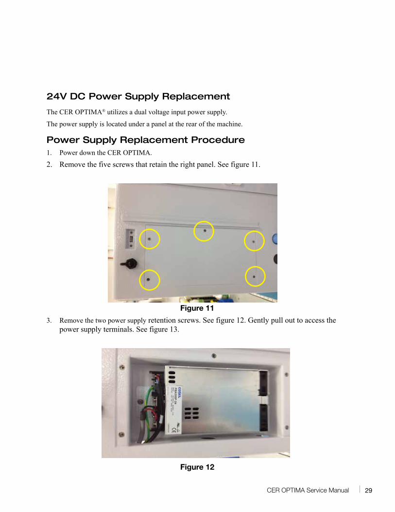
24V DC Power Supply Replacement
The CER OPTIMA® utilizes a dual voltage input power supply.
The power supply is located under a panel at the rear of the machine.
Power Supply Replacement Procedure1. Power down the CER OPTIMA.
2. Remove the five screws that retain the right panel. See figure 11.
Figure 11
3. Remove the two power supply retention screws. See figure 12. Gently pull out to access the power supply terminals. See figure 13.
Figure 12
30 CER OPTIMA Service Manual
Figure 13
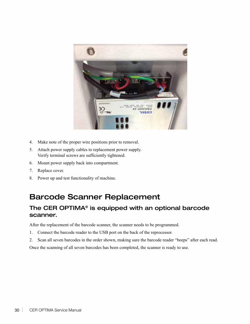
4. Make note of the proper wire positions prior to removal.
5. Attach power supply cables to replacement power supply. Verify terminal screws are sufficiently tightened.
6. Mount power supply back into compartment.
7. Replace cover.
8. Power up and test functionality of machine.
Barcode Scanner ReplacementThe CER OPTIMA® is equipped with an optional barcode scanner.
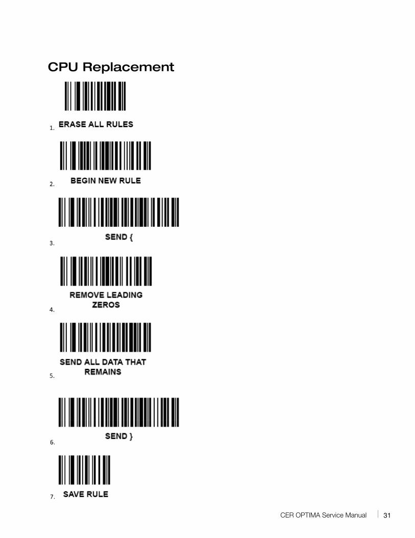
After the replacement of the barcode scanner, the scanner needs to be programmed.
1. Connect the barcode reader to the USB port on the back of the reprocessor.
2. Scan all seven barcodes in the order shown, making sure the barcode reader “beeps” after each read.
Once the scanning of all seven barcodes has been completed, the scanner is ready to use.
31CER OPTIMA Service Manual
CPU Replacement
32 CER OPTIMA Service Manual
Removal Procedure• Remove power to the machine.
• Remove the five screws retaining the cover plate.
• Disconnect all cable harnesses. To gain better access to the ribbon cables, it may be necessary to set the machine on its side and remove the lower panel for better access.
• Remove the six board retaining screws
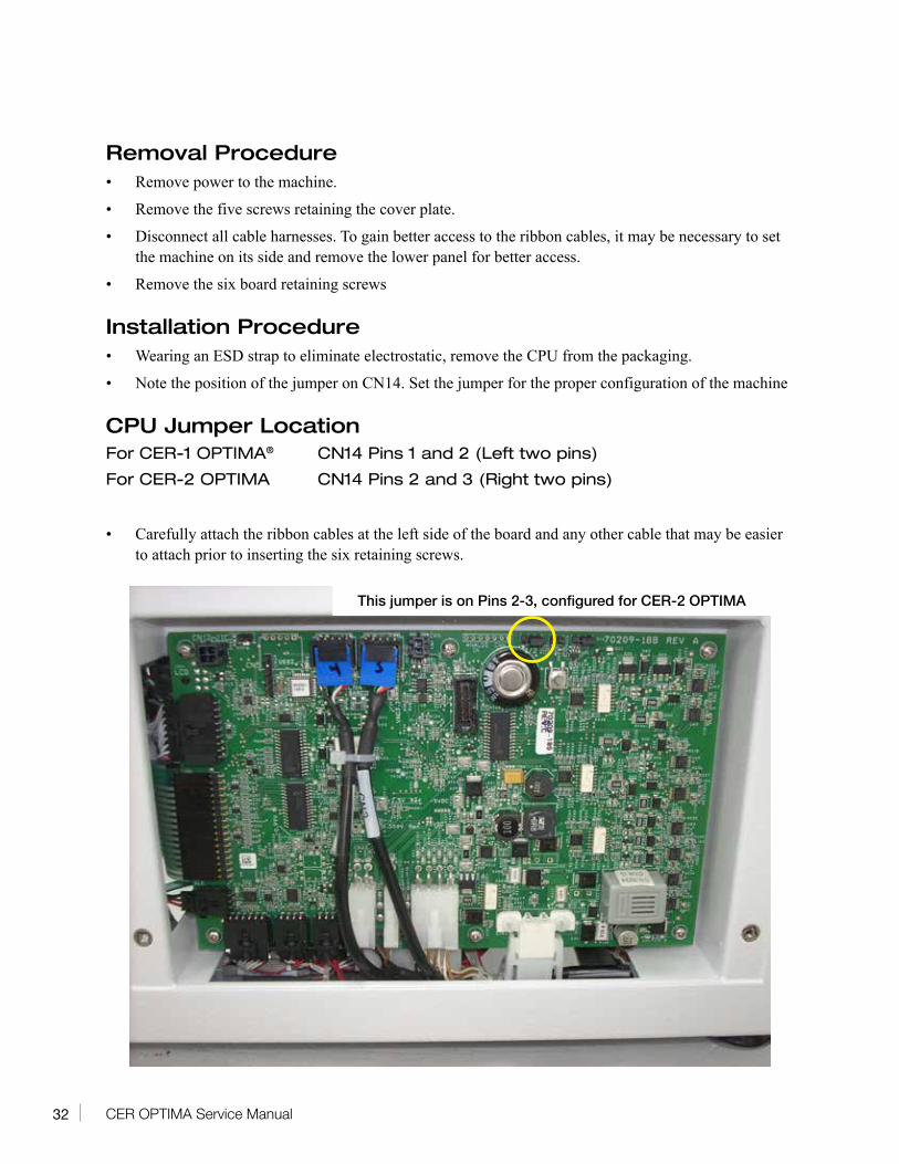
Installation Procedure• Wearing an ESD strap to eliminate electrostatic, remove the CPU from the packaging.
• Note the position of the jumper on CN14. Set the jumper for the proper configuration of the machine
CPU Jumper LocationFor CER-1 OPTIMA® CN14 Pins 1 and 2 (Left two pins)
For CER-2 OPTIMA CN14 Pins 2 and 3 (Right two pins)
• Carefully attach the ribbon cables at the left side of the board and any other cable that may be easier
to attach prior to inserting the six retaining screws.
This jumper is on Pins 2-3, configured for CER-2 OPTIMA
33CER OPTIMA Service Manual
• Insert and tighten the six retaining screws.
• Connect any other cables that have not yet been reattached.
• Replace all covers.
• Power up the machine and test.
• Set the time and date. Refer to user functions in the CER OPTIMA® operation manual.
34 CER OPTIMA Service Manual
Channel Pump
The CER OPTIMA® internal channel pump performs various duties in the cycle of the reprocessor. The pump pushes fluid through the endoscope connectors during various phases of the cycle and also assists the disinfectant back to the reservoir and rinse water to the drain. Please note, the pump only assists and draining is dependent on gravity. The pump is not designed to pump fluid higher than the bottom of the reprocessor. This is the reason that the reservoir return hoses and drain lines must go down from the back of the machine, and never loop above the drain fittings.
The Channel pump is a 120VAC pump that has two line fuses in the chassis. Refer to the section on fuse replacement for further details
Channel Pump Replacement1. Verify all fluid has been drained from the basin.
2. Remove the power to the machine.
3. Set the CER OPTIMA on its left side. Depending on the plumbing situation, hoses may need to be disconnected to allow for this to occur.
4. Remove the bottom cover from the reprocessor.
5. Locate the Channel pump. See figure 14.
35CER OPTIMA Service Manual
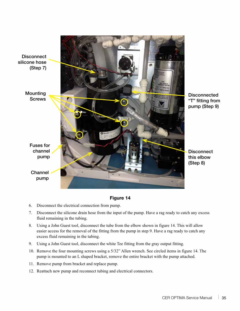
Figure 14
6. Disconnect the electrical connection from pump.
7. Disconnect the silicone drain hose from the input of the pump. Have a rag ready to catch any excess fluid remaining in the tubing.
8. Using a John Guest tool, disconnect the tube from the elbow shown in figure 14. This will allow easier access for the removal of the fitting from the pump in step 9. Have a rag ready to catch any excess fluid remaining in the tubing.
9. Using a John Guest tool, disconnect the white Tee fitting from the gray output fitting.
10. Remove the four mounting screws using a 5/32” Allen wrench. See circled items in figure 14. The pump is mounted to an L shaped bracket, remove the entire bracket with the pump attached.
11. Remove pump from bracket and replace pump.
12. Reattach new pump and reconnect tubing and electrical connectors.
Disconnect silicone hose
(Step 7)
Disconnected “T” fitting from pump (Step 9)
Mounting Screws
Channel pump
Fuses for channel
pumpDisconnect this elbow (Step 8)
36 CER OPTIMA Service Manual
Transfer Pump
The purpose of the transfer pump is to move the disinfectant from the reservoir to the reprocessor basin. The pump is 24 VDC.
Transfer Pump Replacement1. Verify all fluid has been drained from the basin.
2. Remove the power to the machine.
3. Set the CER OPTIMA® on its left side. Depending on the plumbing situation, hoses may need to be disconnected to allow for this to occur.
4. Remove the bottom cover from the reprocessor.
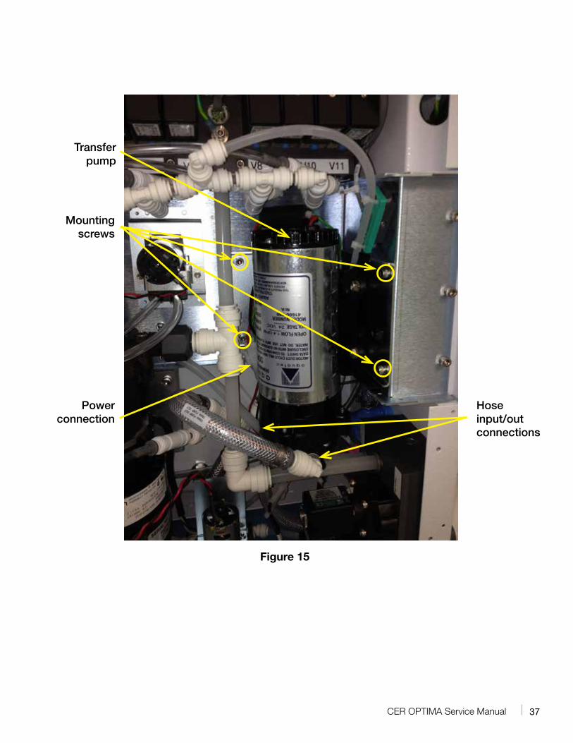
5. Locate the Transfer pump. See figure 15.
6. Disconnect the power connection
7. Using a John Guest tool, disconnect the outside hose connection. Once the pump mounting screws, the inside hose will be accessible.
8. The pump is mounted to an L shape mounting bracket. This bracket with the pump mounted to it, will be removed in this process. Remove the four 5/16” Allen head mounting screws as shown, carefully pull out, then disconnect the backside hose connection.
9. Remove old pump from bracket and attach the new pump to the bracket.
10. While remounting the new pump, attach the rear hose to the pump head before inserting the mounting screws.
11. Attach all screw and tighten.
12. Attach hose and power connection.
13. Attach bottom cover and test.
37CER OPTIMA Service Manual
Mounting screws
Transfer pump
Power connection
Hose input/out connections
Figure 15
38 CER OPTIMA Service Manual
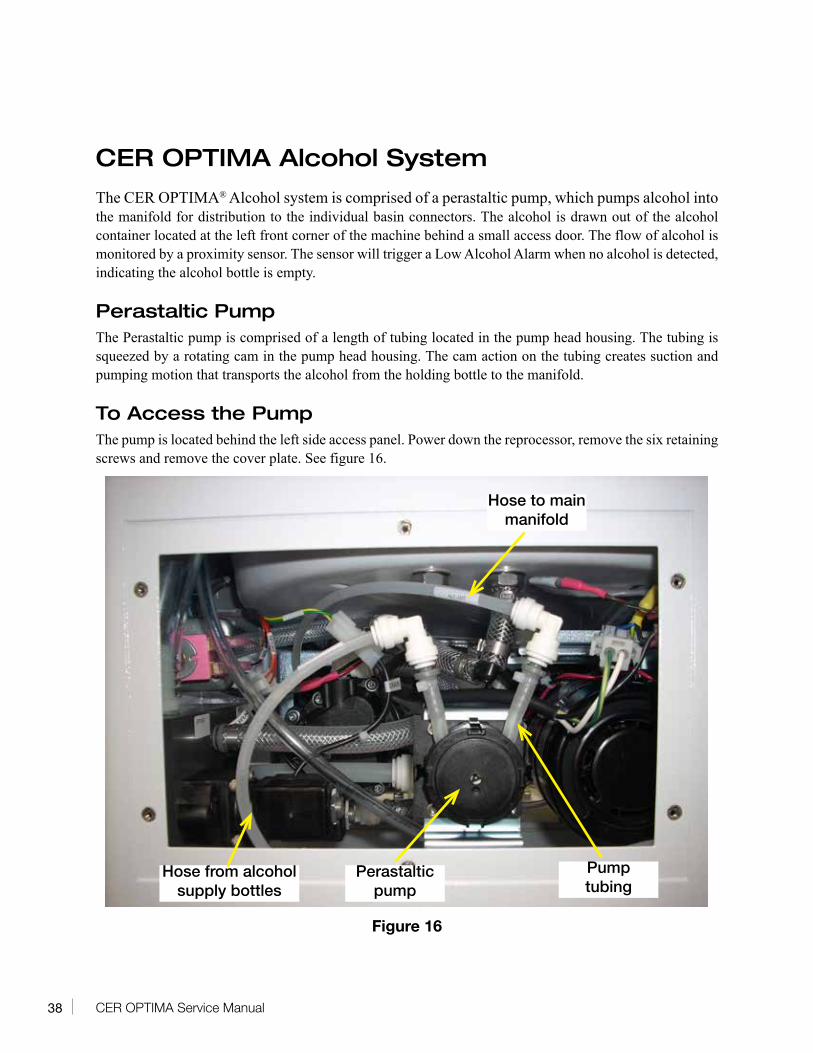
CER OPTIMA Alcohol System
The CER OPTIMA® Alcohol system is comprised of a perastaltic pump, which pumps alcohol into the manifold for distribution to the individual basin connectors. The alcohol is drawn out of the alcohol container located at the left front corner of the machine behind a small access door. The flow of alcohol is monitored by a proximity sensor. The sensor will trigger a Low Alcohol Alarm when no alcohol is detected, indicating the alcohol bottle is empty.
Perastaltic PumpThe Perastaltic pump is comprised of a length of tubing located in the pump head housing. The tubing is squeezed by a rotating cam in the pump head housing. The cam action on the tubing creates suction and pumping motion that transports the alcohol from the holding bottle to the manifold.
To Access the PumpThe pump is located behind the left side access panel. Power down the reprocessor, remove the six retaining screws and remove the cover plate. See figure 16.
Figure 16
Hose to main manifold
Hose from alcohol supply bottles
Perastaltic pump
Pump tubing
39CER OPTIMA Service Manual
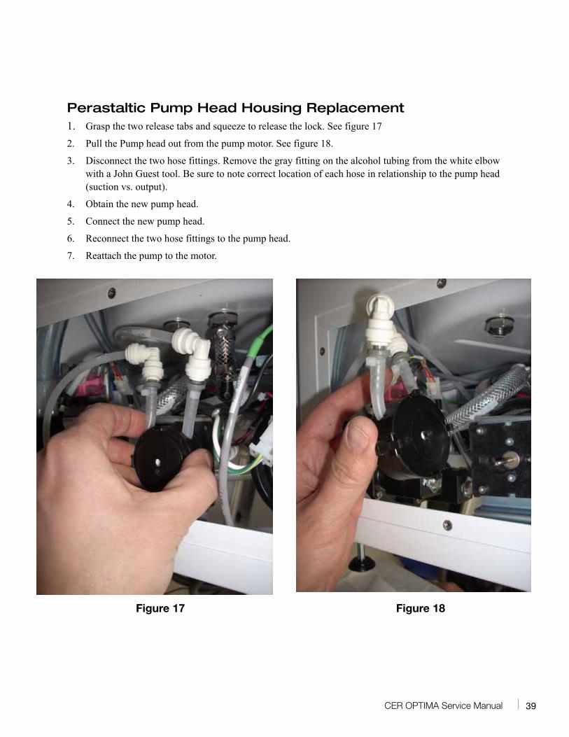
Perastaltic Pump Head Housing Replacement1. Grasp the two release tabs and squeeze to release the lock. See figure 17
2. Pull the Pump head out from the pump motor. See figure 18.
3. Disconnect the two hose fittings. Remove the gray fitting on the alcohol tubing from the white elbow with a John Guest tool. Be sure to note correct location of each hose in relationship to the pump head (suction vs. output).
4. Obtain the new pump head.
5. Connect the new pump head.
6. Reconnect the two hose fittings to the pump head.
7. Reattach the pump to the motor.
Figure 17 Figure 18
40 CER OPTIMA Service Manual
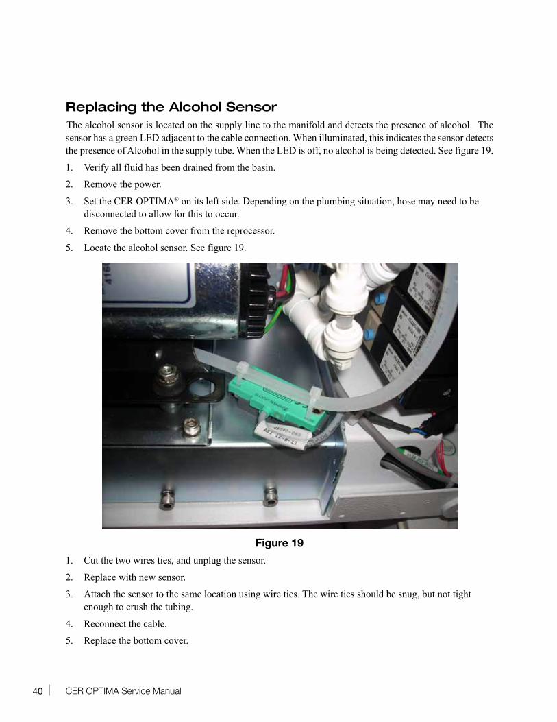
Replacing the Alcohol SensorThe alcohol sensor is located on the supply line to the manifold and detects the presence of alcohol. The sensor has a green LED adjacent to the cable connection. When illuminated, this indicates the sensor detects the presence of Alcohol in the supply tube. When the LED is off, no alcohol is being detected. See figure 19.
1. Verify all fluid has been drained from the basin.
2. Remove the power.
3. Set the CER OPTIMA® on its left side. Depending on the plumbing situation, hose may need to be disconnected to allow for this to occur.
4. Remove the bottom cover from the reprocessor.
5. Locate the alcohol sensor. See figure 19.
Figure 19
1. Cut the two wires ties, and unplug the sensor.
2. Replace with new sensor.
3. Attach the sensor to the same location using wire ties. The wire ties should be snug, but not tight enough to crush the tubing.
4. Reconnect the cable.
5. Replace the bottom cover.
41CER OPTIMA Service Manual
Changing the Disinfectant Type
The CER OPTIMA® ships from the factory programmed for RAPICIDE® High-Level Disinfectant. If the CER OPTIMA is to be used with a different disinfectant type (such as OPA or Glutaraldehyde), follow the instructions below to reprogram the machine.
Changing the type of high-level disinfectant used by the CER OPTIMA can be performed anytime the machine is in an idle state. The Quality Assurance test does not need to be performed prior to making this change.
Each program is fixed. Disinfectant contact time, number of rinses and temperature alarms cannot be modified. User selectable options (Incremental Air, Alcohol inject and washes prior to disinfection) are adjustable. Refer to operations manual for further details on these functions.
Disinfectant optionsNorth American Options International Options
DISINFECTANT TYPE SPECIFICATIONS DISINFECTANT TYPE SPECIFICATIONS
RAPICIDE 5 min, 35ºC 2 rinses RAP OPA INT 5 min, 20ºC 2 rinses
RAP OPA/28 5 min, 25ºC 2 rinses ADASPOR RTU 5 min, 20ºC 1 rinses
RAP OPA/28 10 min, 20ºC 2 rinses ADASPOR RTU 10 min, 20ºC 1 rinses
OPA 12 min, 20ºC 3 rinses ADASPOR RTU 10 min, 20ºC 2 rinses
GLUT 20 min, 20ºC 2 rinses PERASCOPE 10 min, 20ºC 2 rinses
GLUT 20 min, 25ºC 2 rinses ANIOXIDE 10 min, 20ºC 2 rinses
GLUT 45 min, 20ºC 2 rinses STERANIOS 10 min, 20ºC 2 rinses
To Change the Disinfectant Type:
1. To place the CER OPTIMA into an idle state, deselect/shut off the AUTOMATIC FULL and HLD/RINSE touch pads, and also the four MANUAL touch pads, so their respective green lights are OFF.
2. Press the ↓ arrow until SERVICE MENU is displayed.
3. To access the SERVICE MENU, press and hold the → arrow and then press the ↓ arrow.
4. The current programmed disinfectant type will now appear on the screen.
Note: The factory default is set for RAPICIDE High-Level Disinfectant.
For North America: Proceed to line 5.
For International: Press the ↓arrow key one time and INT’L DISINFECTANT should be displayed. Press the → arrow until the desired disinfectant type is displayed. Proceed to step 6.
5. Press the → arrow until the desired disinfectant type is displayed.
42 CER OPTIMA Service Manual
6. Press ENTER to select the disinfectant: the CER OPTIMA is now programmed to this disinfectant.
7. Use the ↓ arrow to scroll through the remaining user-selectable menu screens.
8. EXTENDED RINSES: If extended rinse times are required, press → to select YES and press ENTER to change. Press ↓ to move to next function.
9. CONTINUOUS RUN: This funtion should always set to NO.
10. SPECIAL TESTING: This function should always be set to OFF.
11. MACHINE CYCLE RESET: This value displayed is the overall machine cycle count. This value should never be reset. Press ↓ to move to the next function.
12. SCAN SERIAL NUMBER: The machine serial number will be displayed. Consult MEDIVATORS Technical Support before attempting to change this value.
13. Press ↓ will exit the SERVICE MENU and return to the CER OPTIMA’s idle state.
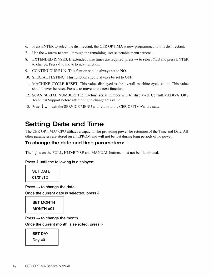
Setting Date and TimeThe CER OPTIMA® CPU utilizes a capacitor for providing power for retention of the Time and Date. All other parameters are stored on an EPROM and will not be lost during long periods of no power.
To change the date and time parameters:
The lights on the FULL, HLD/RINSE and MANUAL buttons must not be illuminated.
Press ↓ until the following is displayed:
SET DATE
01/01/12
Press → to change the date
Once the current date is selected, press ↓
SET MONTH
MONTH =01
Press → to change the month.
Once the current month is selected, press ↓
SET DAY
Day =01
43CER OPTIMA Service Manual
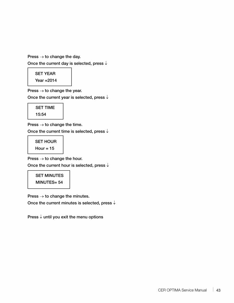
Press → to change the day.
Once the current day is selected, press ↓
SET YEAR
Year =2014
Press → to change the year.
Once the current year is selected, press ↓
SET TIME
15:54
Press → to change the time.
Once the current time is selected, press ↓
SET HOUR
Hour = 15
Press → to change the hour.
Once the current hour is selected, press ↓
SET MINUTES
MINUTES= 54
Press → to change the minutes.
Once the current minutes is selected, press ↓
Press ↓ until you exit the menu options
44 CER OPTIMA Service Manual
Error and Warning Messages
Error messages are displayed on the LCD screen to alert the operator of operational malfunctions and/or operational warnings (see the Appendix for message definitions). If the suggested solutions do not correct the problem or if the problem reoccurs contact customer support.
LOW WATER LEVEL - If the basin is NOT full of water at the time of the alarm
Problem Solution
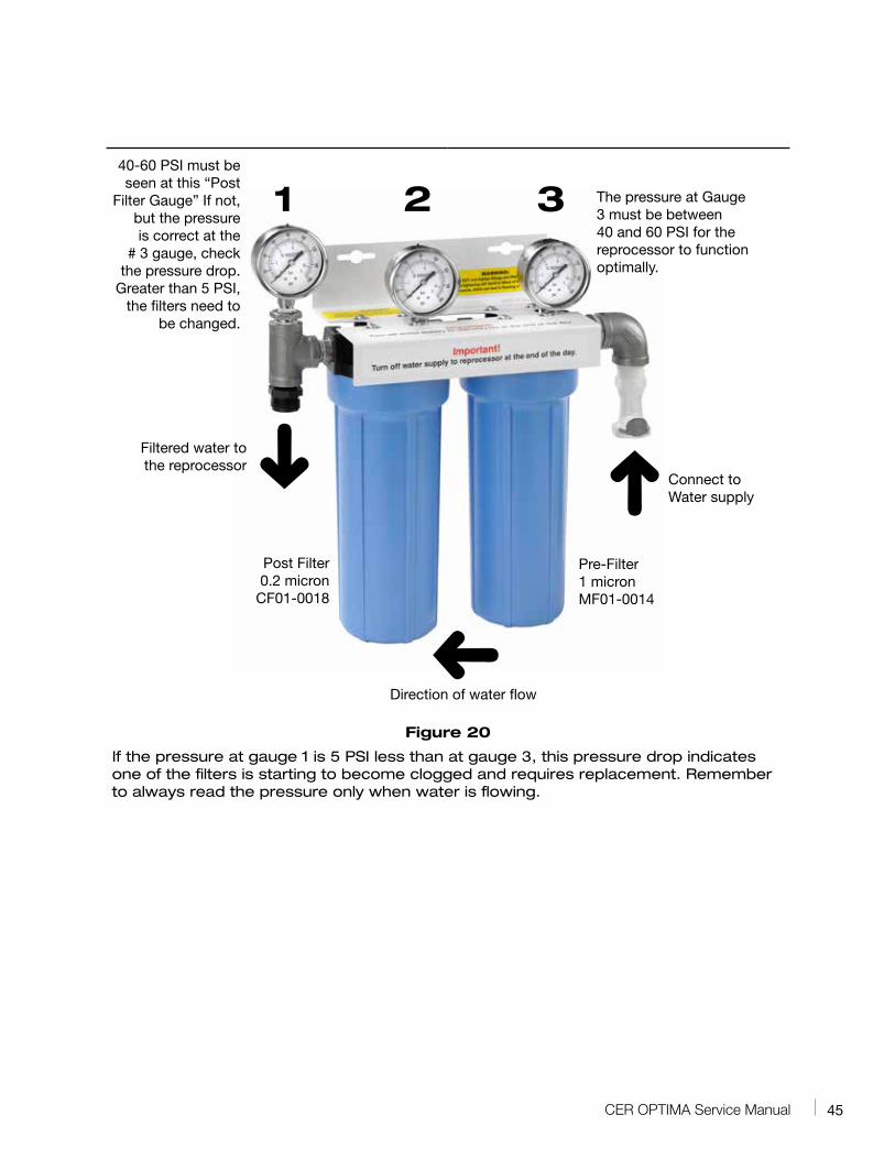
Incoming water pressure is too low Verify water pressure is between 40 and 60 PSI: This pressure must be present at the post (0.2µ) filter of the filter unit, see figure 20. The CER OPTIMA is designed to operate within this pressure range. Water pressure outside of this range can cause operational errors. If pressure is outside this range, contact a qualified plumber to obtain water pressure within this range.
If using pressure regulators or booster pumps, these devices require periodic (typically yearly) maintenance to continue to operate at optimum specifications.
Water Filters clogged Replace water filters: To verify if the filters are clogged, a simple check of the pressure differential is made. The pressure differential must be checked when water is flowing (Dynamic pressure). Even with clogged filters, if pressure is checked when no water is flowing (Static pressure), the water pressure can appear to be correct, but is not. To check the pressure, simply start a cycle and observe the three pressure gauges during the initial fills. If the pressure differential from the first to the last gauge is greater than 5 PSI, the filters should be changed.
IMPORTANT, the incoming pressure cannot be lower than 40 PSI into the filter unit.
The 0.2 micron filter (CF01-0018) must be changed at least once every six (6) months and the 1 micron filter (MF01-0014) at least once every three (3) months.
45CER OPTIMA Service Manual
Figure 20
If the pressure at gauge 1 is 5 PSI less than at gauge 3, this pressure drop indicates one of the filters is starting to become clogged and requires replacement. Remember to always read the pressure only when water is flowing.
40-60 PSI must be seen at this “Post
Filter Gauge” If not, but the pressure is correct at the
# 3 gauge, check the pressure drop.
Greater than 5 PSI, the filters need to
be changed.
Post Filter0.2 micron
CF01-0018
Pre-Filter1 micronMF01-0014
1 2 3 The pressure at Gauge 3 must be between 40 and 60 PSI for the reprocessor to function optimally.
Filtered water to the reprocessor
Connect to Water supply
Direction of water flow
46 CER OPTIMA Service Manual
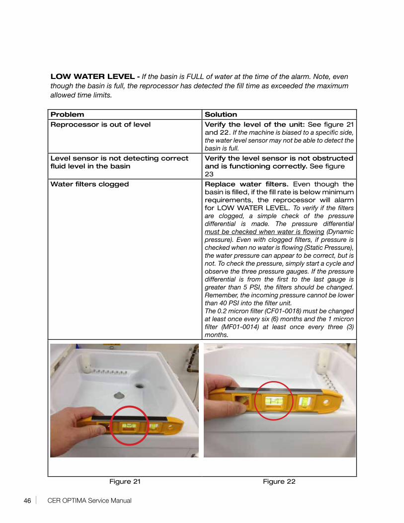
LOW WATER LEVEL - If the basin is FULL of water at the time of the alarm. Note, even though the basin is full, the reprocessor has detected the fill time as exceeded the maximum allowed time limits.
Problem Solution
Reprocessor is out of level Verify the level of the unit: See figure 21 and 22. If the machine is biased to a specific side, the water level sensor may not be able to detect the basin is full.
Level sensor is not detecting correct fluid level in the basin
Verify the level sensor is not obstructed and is functioning correctly. See figure 23
Water filters clogged Replace water filters. Even though the basin is filled, if the fill rate is below minimum requirements, the reprocessor will alarm for LOW WATER LEVEL. To verify if the filters are clogged, a simple check of the pressure differential is made. The pressure differential must be checked when water is flowing (Dynamic pressure). Even with clogged filters, if pressure is checked when no water is flowing (Static Pressure), the water pressure can appear to be correct, but is not. To check the pressure, simply start a cycle and observe the three pressure gauges. If the pressure differential is from the first to the last gauge is greater than 5 PSI, the filters should be changed. Remember, the incoming pressure cannot be lower than 40 PSI into the filter unit.The 0.2 micron filter (CF01-0018) must be changed at least once every six (6) months and the 1 micron filter (MF01-0014) at least once every three (3) months.
Figure 21 Figure 22
47CER OPTIMA Service Manual
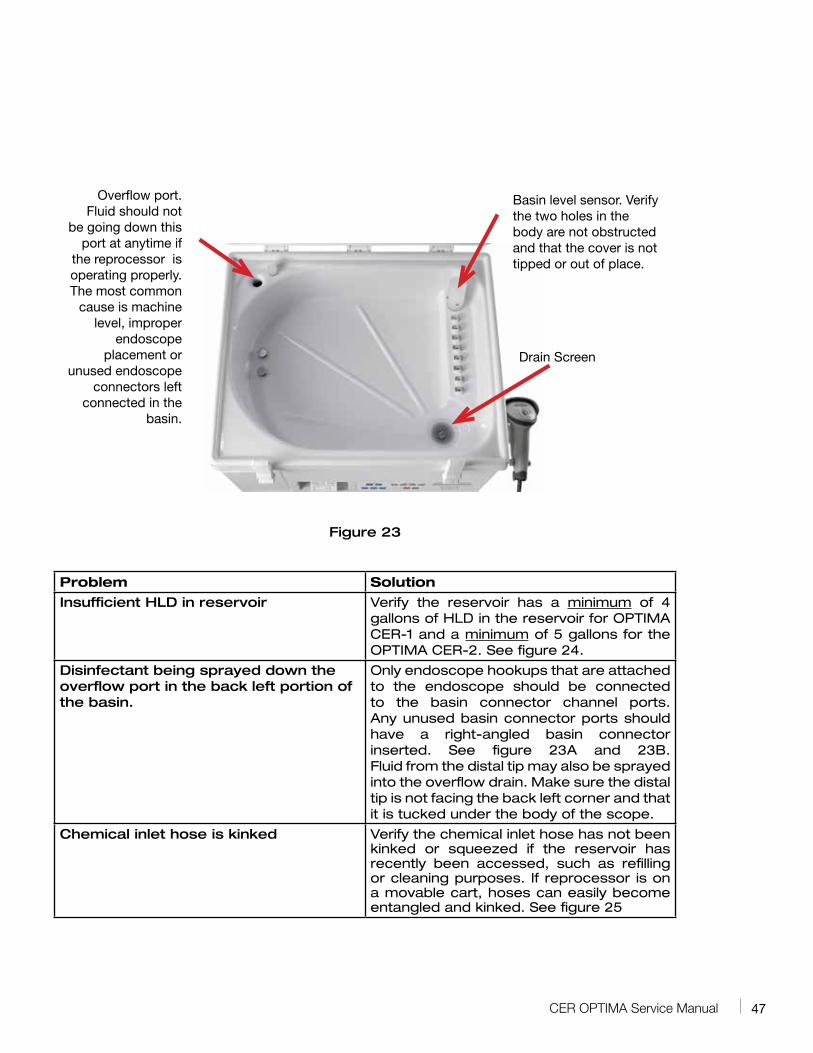
Figure 23
Problem Solution
Insufficient HLD in reservoir Verify the reservoir has a minimum of 4 gallons of HLD in the reservoir for OPTIMA CER-1 and a minimum of 5 gallons for the OPTIMA CER-2. See figure 24.
Disinfectant being sprayed down the overflow port in the back left portion of the basin.
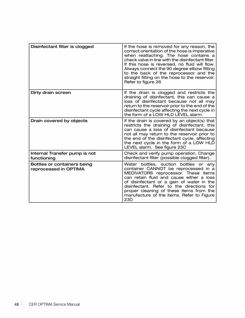
Only endoscope hookups that are attached to the endoscope should be connected to the basin connector channel ports. Any unused basin connector ports should have a right-angled basin connector inserted. See figure 23A and 23B. Fluid from the distal tip may also be sprayed into the overflow drain. Make sure the distal tip is not facing the back left corner and that it is tucked under the body of the scope.
Chemical inlet hose is kinked Verify the chemical inlet hose has not been kinked or squeezed if the reservoir has recently been accessed, such as refilling or cleaning purposes. If reprocessor is on a movable cart, hoses can easily become entangled and kinked. See figure 25
Overflow port. Fluid should not
be going down this port at anytime if
the reprocessor is operating properly. The most common
cause is machine level, improper
endoscope placement or
unused endoscope connectors left
connected in the basin.
Basin level sensor. Verify the two holes in the body are not obstructed and that the cover is not tipped or out of place.
Drain Screen
48 CER OPTIMA Service Manual
Disinfectant filter is clogged If the hose is removed for any reason, the correct orientation of the hose is imperative when reattaching. The hose contains a check valve in line with the disinfectant filter. If this hose is reversed, no fluid will flow. Always connect the 90 degree elbow fitting to the back of the reprocessor and the straight fitting on the hose to the reservoir. Refer to figure 26
Dirty drain screen If the drain is clogged and restricts the draining of disinfectant, this can cause a loss of disinfectant because not all may return to the reservoir prior to the end of the disinfectant cycle affecting the next cycle in the form of a LOW HLD LEVEL alarm.
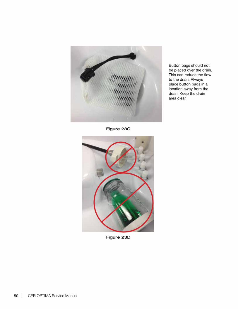
Drain covered by objects If the drain is covered by an object(s) that restricts the draining of disinfectant, this can cause a loss of disinfectant because not all may return to the reservoir prior to the end of the disinfectant cycle, affecting the next cycle in the form of a LOW HLD LEVEL alarm. See figure 23C
Internal Transfer pump is not functioning
Check and verify pump operation. Change disinfectant filter (possible clogged filter).
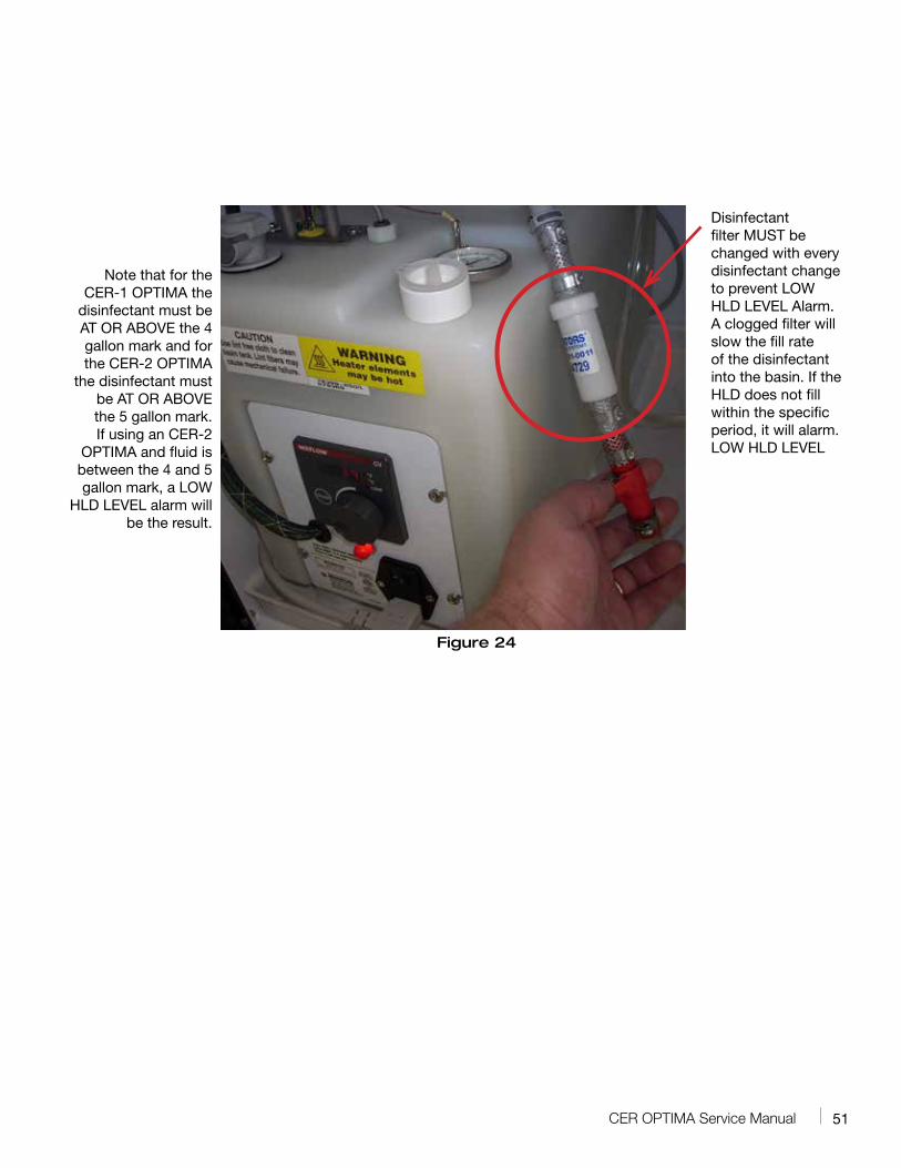
Bottles or containers being reprocessed in OPTIMA
Water bottles, suction bottles or any container CANNOT be reprocessed in a MEDIVATORS reprocessor. These items can retain fluid and cause either a loss of disinfectant or a gain of water in the disinfectant. Refer to the directions for proper cleaning of these items from the manufacture of the items. Refer to Figure 23D
49CER OPTIMA Service Manual
Figure 23A
Figure 23B
Right-angled basin connectors (shown in this
figure) should be inserted in any basin channel port that are not being used. NEVER
leave unused endoscope hookups in the basin that
are not connected to an endoscope. This practice
can lead to disinfectant being sprayed down the overflow
drain.
Do not leave endoscope hook ups in the basin that are not attached to an endoscope.
The spray or turbulence caused by this loose hook up
can cause HLD loss.
50 CER OPTIMA Service Manual
Figure 23C
Figure 23D
Button bags should not be placed over the drain. This can reduce the flow to the drain. Always place button bags in a location away from the drain. Keep the drain area clear.
51CER OPTIMA Service Manual
Figure 24
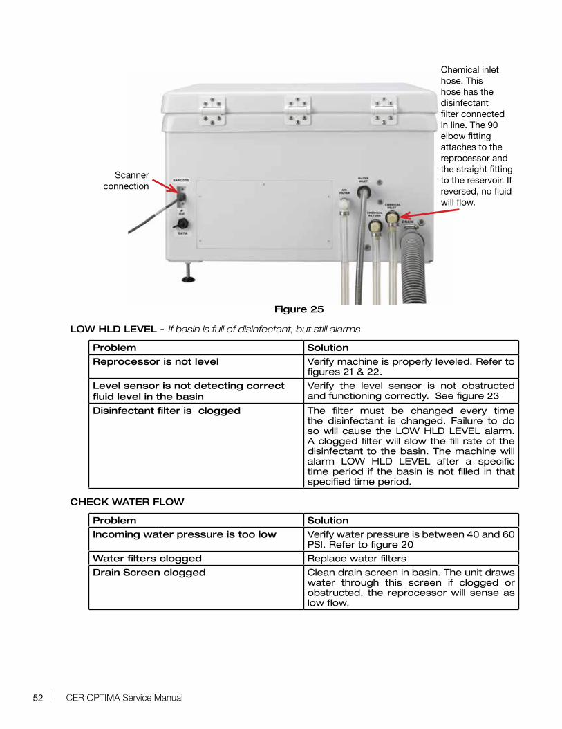
Disinfectant filter MUST be changed with every disinfectant change to prevent LOW HLD LEVEL Alarm. A clogged filter will slow the fill rate of the disinfectant into the basin. If the HLD does not fill within the specific period, it will alarm. LOW HLD LEVEL
Note that for the CER-1 OPTIMA the
disinfectant must be AT OR ABOVE the 4 gallon mark and for the CER-2 OPTIMA
the disinfectant must be AT OR ABOVE the 5 gallon mark. If using an CER-2
OPTIMA and fluid is between the 4 and 5 gallon mark, a LOW
HLD LEVEL alarm will be the result.
52 CER OPTIMA Service Manual
Figure 25
LOW HLD LEVEL - If basin is full of disinfectant, but still alarms
Problem Solution
Reprocessor is not level Verify machine is properly leveled. Refer to figures 21 & 22.
Level sensor is not detecting correct fluid level in the basin
Verify the level sensor is not obstructed and functioning correctly. See figure 23
Disinfectant filter is clogged The filter must be changed every time the disinfectant is changed. Failure to do so will cause the LOW HLD LEVEL alarm. A clogged filter will slow the fill rate of the disinfectant to the basin. The machine will alarm LOW HLD LEVEL after a specific time period if the basin is not filled in that specified time period.
CHECK WATER FLOW
Problem Solution
Incoming water pressure is too low Verify water pressure is between 40 and 60 PSI. Refer to figure 20
Water filters clogged Replace water filters
Drain Screen clogged Clean drain screen in basin. The unit draws water through this screen if clogged or obstructed, the reprocessor will sense as low flow.
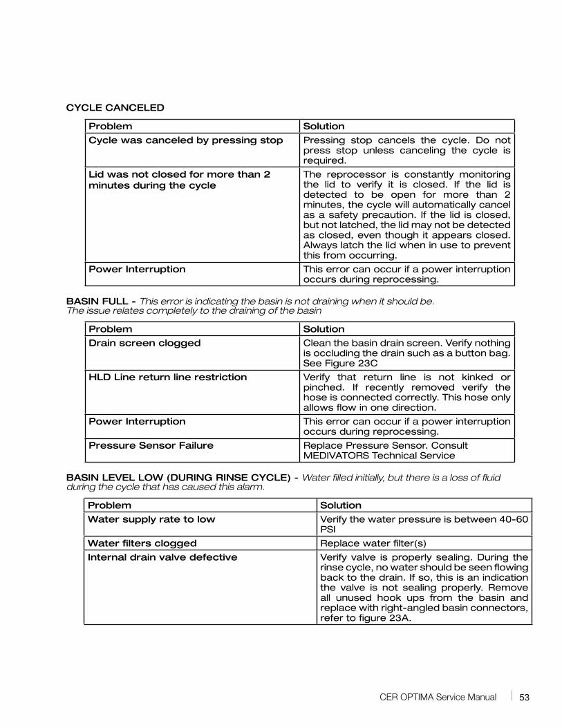
Chemical inlet hose. This hose has the disinfectant filter connected in line. The 90 elbow fitting attaches to the reprocessor and the straight fitting to the reservoir. If reversed, no fluid will flow.
Scanner connection
53CER OPTIMA Service Manual
CYCLE CANCELED
Problem Solution
Cycle was canceled by pressing stop Pressing stop cancels the cycle. Do not press stop unless canceling the cycle is required.
Lid was not closed for more than 2 minutes during the cycle
The reprocessor is constantly monitoring the lid to verify it is closed. If the lid is detected to be open for more than 2 minutes, the cycle will automatically cancel as a safety precaution. If the lid is closed, but not latched, the lid may not be detected as closed, even though it appears closed. Always latch the lid when in use to prevent this from occurring.
Power Interruption This error can occur if a power interruption occurs during reprocessing.
BASIN FULL - This error is indicating the basin is not draining when it should be. The issue relates completely to the draining of the basin
Problem Solution
Drain screen clogged Clean the basin drain screen. Verify nothing is occluding the drain such as a button bag. See Figure 23C
HLD Line return line restriction Verify that return line is not kinked or pinched. If recently removed verify the hose is connected correctly. This hose only allows flow in one direction.
Power Interruption This error can occur if a power interruption occurs during reprocessing.
Pressure Sensor Failure Replace Pressure Sensor. Consult MEDIVATORS Technical Service
BASIN LEVEL LOW (DURING RINSE CYCLE) - Water filled initially, but there is a loss of fluid during the cycle that has caused this alarm.
Problem Solution
Water supply rate to low Verify the water pressure is between 40-60 PSI
Water filters clogged Replace water filter(s)
Internal drain valve defective Verify valve is properly sealing. During the rinse cycle, no water should be seen flowing back to the drain. If so, this is an indication the valve is not sealing properly. Remove all unused hook ups from the basin and replace with right-angled basin connectors, refer to figure 23A.
54 CER OPTIMA Service Manual
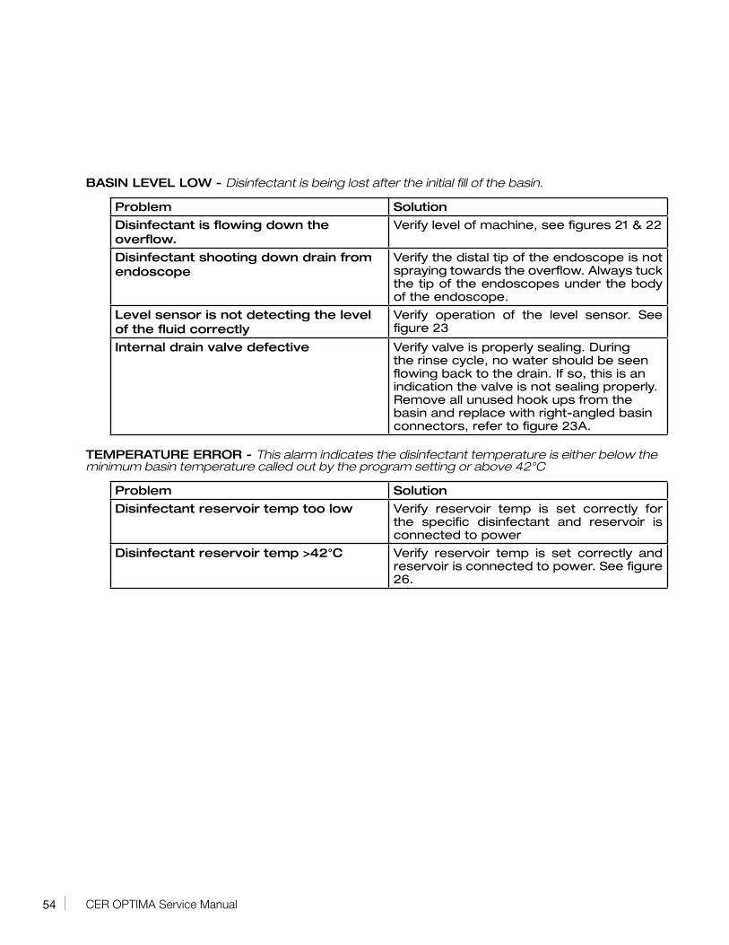
BASIN LEVEL LOW - Disinfectant is being lost after the initial fill of the basin.
Problem Solution
Disinfectant is flowing down the overflow.
Verify level of machine, see figures 21 & 22
Disinfectant shooting down drain from endoscope
Verify the distal tip of the endoscope is not spraying towards the overflow. Always tuck the tip of the endoscopes under the body of the endoscope.
Level sensor is not detecting the level of the fluid correctly
Verify operation of the level sensor. See figure 23
Internal drain valve defective Verify valve is properly sealing. During the rinse cycle, no water should be seen flowing back to the drain. If so, this is an indication the valve is not sealing properly. Remove all unused hook ups from the basin and replace with right-angled basin connectors, refer to figure 23A.
TEMPERATURE ERROR - This alarm indicates the disinfectant temperature is either below the minimum basin temperature called out by the program setting or above 42°C
Problem Solution
Disinfectant reservoir temp too low Verify reservoir temp is set correctly for the specific disinfectant and reservoir is connected to power
Disinfectant reservoir temp >42°C Verify reservoir temp is set correctly and reservoir is connected to power. See figure 26.
55CER OPTIMA Service Manual
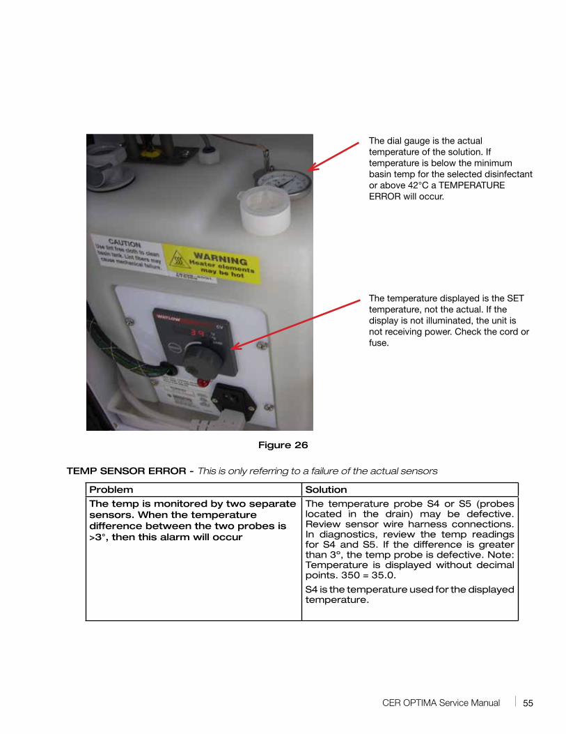
Figure 26
TEMP SENSOR ERROR - This is only referring to a failure of the actual sensors
Problem Solution
The temp is monitored by two separate sensors. When the temperature difference between the two probes is >3°, then this alarm will occur
The temperature probe S4 or S5 (probes located in the drain) may be defective. Review sensor wire harness connections. In diagnostics, review the temp readings for S4 and S5. If the difference is greater than 3º, the temp probe is defective. Note: Temperature is displayed without decimal points. 350 = 35.0.
S4 is the temperature used for the displayed temperature.
The dial gauge is the actual temperature of the solution. If temperature is below the minimum basin temp for the selected disinfectant or above 42°C a TEMPERATURE ERROR will occur.
The temperature displayed is the SET temperature, not the actual. If the display is not illuminated, the unit is not receiving power. Check the cord or fuse.
56 CER OPTIMA Service Manual
BASIN DRAIN TIMEOUT - Only occurs when BASIN TO DRAIN button is pressed
Problem Solution
Drain screen clogged Clean drain screen or remove any object that maybe covering the drain screen.
HLD line restriction Verify there are no kinks in HLD hose
Pressure sensor is defective Possible defective pressure sensor
Channel Pump is defective Verify pump operation. Repair/Replace if necessary
LOW CHAN PRESSURE - During the rinse cycle
Problem Solution
Drain screen clogged Clean drain screen. Prevent endoscopes or other objects from covering the drain.
Water supply is turned off Turn on water supply
Pressure sensor defective Possible defective pressure sensor
Channel pump is not pumping Inspect Channel Pump. Verify the Chemical inlet hose is not kinked or disconnected.
LOW CHAN PRESSURE - During HLD portion of cycle
Problem Solution
Drain screen clogged Clean drain screen. Prevent endoscopes or other objects from covering the drain.
Disinfectant reservoir empty Fill reservoir
Disinfectant supply line restriction Remove restriction from line; verify the supply line is connected and that the disinfectant filter is properly connected.
Disinfectant filter clogged Replace disinfectant filter. Change after every disinfectant change.
Channel pump not pumping Inspect channel pump
Pressure sensor defective Possible defective pressure sensor
NVRAM - This error can occur at any point in the cycle
Problem Solution
Internal Communication fault. May occur during a power fluctuation
• If either the FULL or HLD RINSE button is illuminated, press it to turn it off.
• Press the down arrow until you see HLD CYCLE CNT RESET.
• Press the arrow. Then press ENTER to accept the change.
• Reselect the FULL or HLD RINSE cycle and run a test cycle. The customer may need to power the unit up and down.
57CER OPTIMA Service Manual
Error ConditionsNot tied to a specific error
AFTER THE COMPLETION OF ONE CYCLE, ANOTHER CYCLE IMMEDITALY STARTS
Problem Solution
The CONTIUNOUS RUN function has been activated
In the SERVICE MENU this option should be set to NO. If not changed from YES to NO. Refer to the OPTIMA USER manual for details
SCANNER DOES NOT READ BAR CODES
Problem Solution
Scanner not activated Verify in the sub menu that the scanner is activated. Refer to the OPTIMA USER manual for details
Scanner not plugged in Verify the scanner is plugged in to the back of the reprocessor. Refer to figure 25.
Scanner requires reprogramming Refer to the BARCODE SCANNER REPLACEMENT section of the repair manual.
RESERVOIR GAINING VOLUME
Problem Solution
Water in basin at the end of the initial rinse cycle.
If using HLD Rinse and water pressure is too great. If pressure is too high, water can be carried over from the initial rinse into the disinfectant.
Fluid remaining in basin at end of cycle Check machine level. If out of level, fluid cannot completely return to the drain.
Obstruction in basin Clean the drain screen
Bottles or containers being reprocessed in OPTIMA
Water bottles, suction bottles or any container CANNOT be reprocessed in a MEDIVATORS reprocessor. These items can retain fluid and cause either a loss of disinfectant or a gain of water in the disinfectant. Refer the directions for proper cleaning of these items from the manufacture of the items. Refer to figure 23B
Unauthorized items in basin and items covering the drain
Only endoscopes and their related accessories (buttons and caps) are to be reprocessed at the same time. The reprocessing of inappropriate items with endoscopes can, depending on the circumstance cause either gain or loss. There are a certain number of soak only devices that can be reprocessed, but must be reprocessed independently of endoscopes and adhering to the guidelines outlined in the document SOAK ONLY DEVICES MAY BE REPROCESSED IN MEDIVATORS AER’S. Bulletin number 50097-478 found at www.medivators.com.
58 CER OPTIMA Service Manual
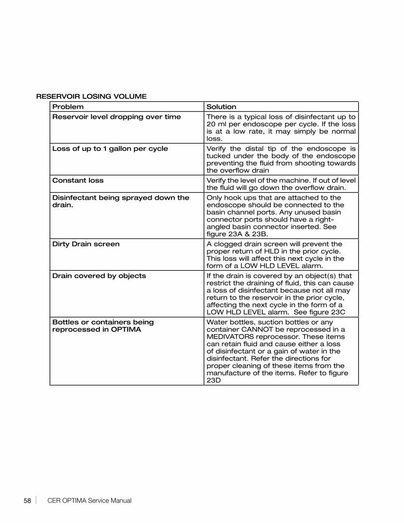
RESERVOIR LOSING VOLUME
Problem Solution
Reservoir level dropping over time There is a typical loss of disinfectant up to 20 ml per endoscope per cycle. If the loss is at a low rate, it may simply be normal loss.
Loss of up to 1 gallon per cycle Verify the distal tip of the endoscope is tucked under the body of the endoscope preventing the fluid from shooting towards the overflow drain
Constant loss Verify the level of the machine. If out of level the fluid will go down the overflow drain.
Disinfectant being sprayed down the drain.
Only hook ups that are attached to the endoscope should be connected to the basin channel ports. Any unused basin connector ports should have a right-angled basin connector inserted. See figure 23A & 23B.
Dirty Drain screen A clogged drain screen will prevent the proper return of HLD in the prior cycle. This loss will affect this next cycle in the form of a LOW HLD LEVEL alarm.
Drain covered by objects If the drain is covered by an object(s) that restrict the draining of fluid, this can cause a loss of disinfectant because not all may return to the reservoir in the prior cycle, affecting the next cycle in the form of a LOW HLD LEVEL alarm. See figure 23C
Bottles or containers being reprocessed in OPTIMA
Water bottles, suction bottles or any container CANNOT be reprocessed in a MEDIVATORS reprocessor. These items can retain fluid and cause either a loss of disinfectant or a gain of water in the disinfectant. Refer the directions for proper cleaning of these items from the manufacture of the items. Refer to figure 23D
59CER OPTIMA Service Manual
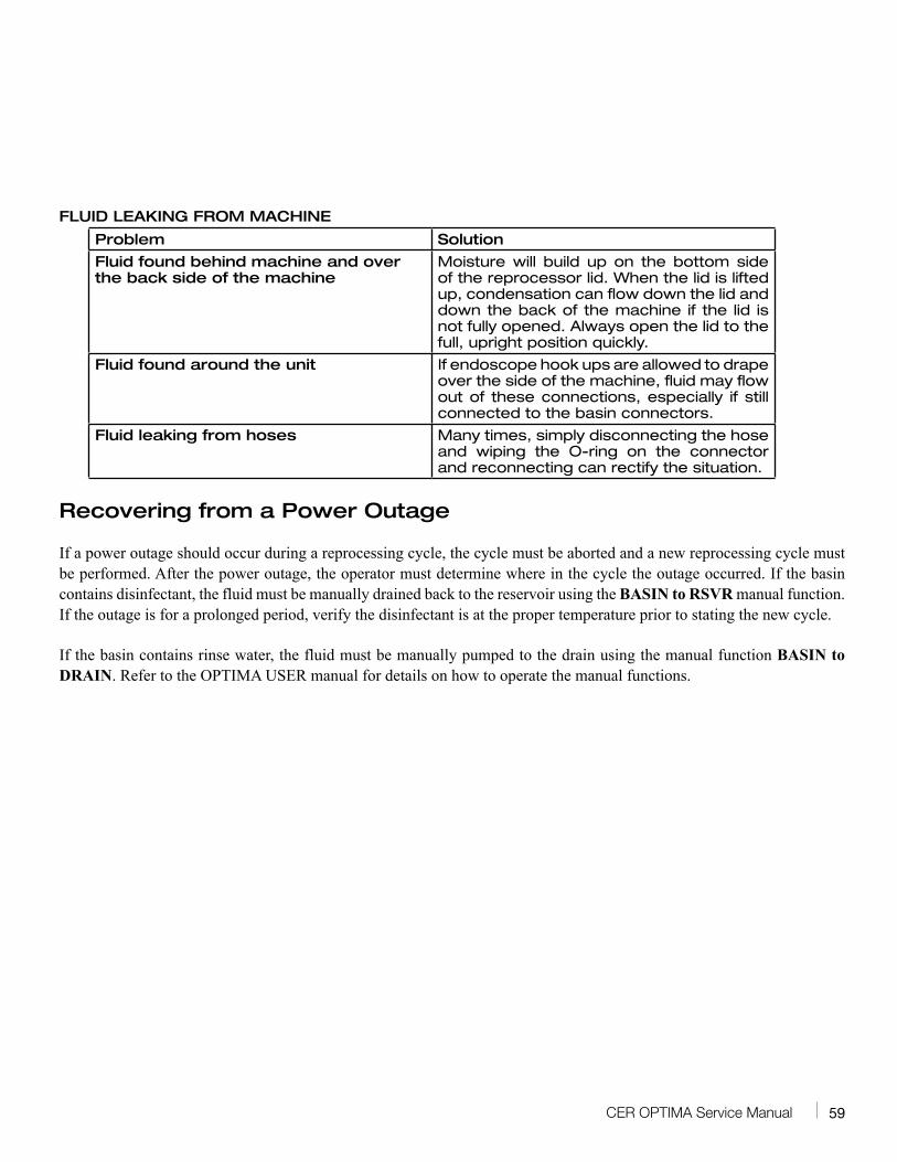
FLUID LEAKING FROM MACHINE
Problem Solution
Fluid found behind machine and over the back side of the machine
Moisture will build up on the bottom side of the reprocessor lid. When the lid is lifted up, condensation can flow down the lid and down the back of the machine if the lid is not fully opened. Always open the lid to the full, upright position quickly.
Fluid found around the unit If endoscope hook ups are allowed to drape over the side of the machine, fluid may flow out of these connections, especially if still connected to the basin connectors.
Fluid leaking from hoses Many times, simply disconnecting the hose and wiping the O-ring on the connector and reconnecting can rectify the situation.
Recovering from a Power Outage
If a power outage should occur during a reprocessing cycle, the cycle must be aborted and a new reprocessing cycle must be performed. After the power outage, the operator must determine where in the cycle the outage occurred. If the basin contains disinfectant, the fluid must be manually drained back to the reservoir using the BASIN to RSVR manual function. If the outage is for a prolonged period, verify the disinfectant is at the proper temperature prior to stating the new cycle.
If the basin contains rinse water, the fluid must be manually pumped to the drain using the manual function BASIN to DRAIN. Refer to the OPTIMA USER manual for details on how to operate the manual functions.
60 CER OPTIMA Service Manual
CER OPTIMA® Diagnostics
IntroductionThe diagnostic functions can be utilized to verify proper component operation when troubleshooting a reprocessor issue.
PrecautionsAlways refer to the Safety section in the Introduction chapter before attempting to service the reprocessor.
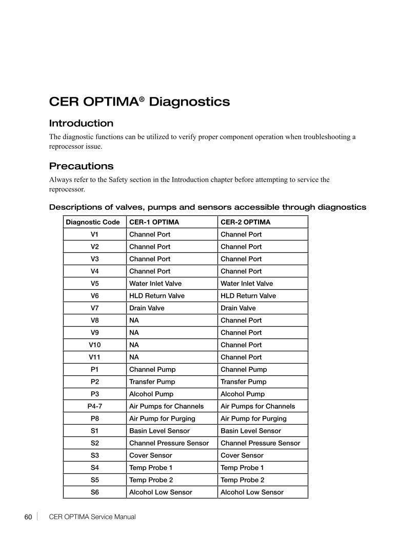
Descriptions of valves, pumps and sensors accessible through diagnostics
Diagnostic Code CER-1 OPTIMA CER-2 OPTIMA
V1 Channel Port Channel Port
V2 Channel Port Channel Port
V3 Channel Port Channel Port
V4 Channel Port Channel Port
V5 Water Inlet Valve Water Inlet Valve
V6 HLD Return Valve HLD Return Valve
V7 Drain Valve Drain Valve
V8 NA Channel Port
V9 NA Channel Port
V10 NA Channel Port
V11 NA Channel Port
P1 Channel Pump Channel Pump
P2 Transfer Pump Transfer Pump
P3 Alcohol Pump Alcohol Pump
P4-7 Air Pumps for Channels Air Pumps for Channels
P8 Air Pump for Purging Air Pump for Purging
S1 Basin Level Sensor Basin Level Sensor
S2 Channel Pressure Sensor Channel Pressure Sensor
S3 Cover Sensor Cover Sensor
S4 Temp Probe 1 Temp Probe 1
S5 Temp Probe 2 Temp Probe 2
S6 Alcohol Low Sensor Alcohol Low Sensor
61CER OPTIMA Service Manual
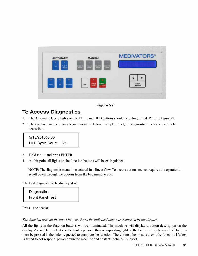
Figure 27
To Access Diagnostics1. The Automatic Cycle lights on the FULL and HLD buttons should be extinguished. Refer to figure 27.
2. The display must be in an idle state as in the below example, if not, the diagnostic functions may not be accessible
5/13/2013 08:30
HLD Cycle Count 25
3. Hold the → and press ENTER
4. At this point all lights on the function buttons will be extinguished
NOTE: The diagnostic menu is structured in a linear flow. To access various menus requires the operator to scroll down through the options from the beginning to end.
The first diagnostic to be displayed is:
Diagnostics
Front Panel Test
Press → to access
This function tests all the panel buttons. Press the indicated button as requested by the display.
All the lights in the function buttons will be illuminated. The machine will display a button description on the display. As each button that is called out is pressed, the corresponding light on the button will extinguish. All buttons must be pressed in the order requested to complete the function. There is no other means to exit the function. If a key is found to not respond, power down the machine and contact Technical Support.
62 CER OPTIMA Service Manual
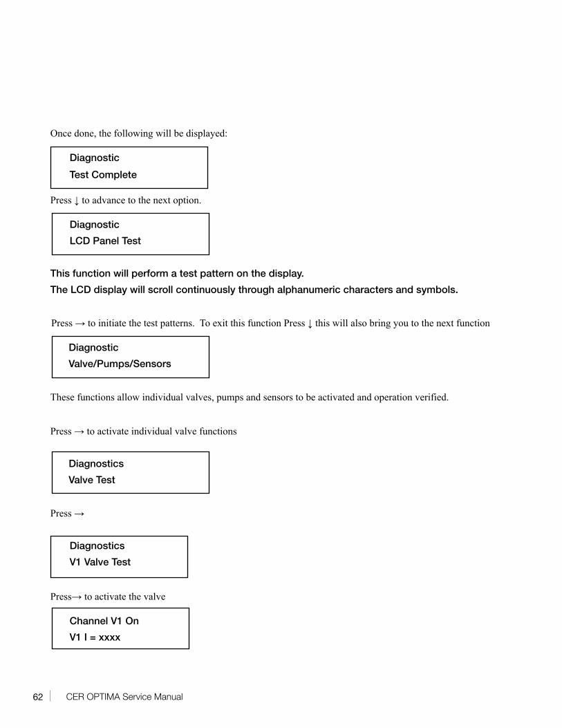
Once done, the following will be displayed:
Diagnostic
Test Complete
Press ↓ to advance to the next option.
Diagnostic
LCD Panel Test
This function will perform a test pattern on the display.
The LCD display will scroll continuously through alphanumeric characters and symbols.
Press → to initiate the test patterns. To exit this function Press ↓ this will also bring you to the next function
Diagnostic
Valve/Pumps/Sensors
These functions allow individual valves, pumps and sensors to be activated and operation verified.
Press → to activate individual valve functions
Diagnostics
Valve Test
Press →
Diagnostics
V1 Valve Test
Press→ to activate the valve
Channel V1 On
V1 I = xxxx
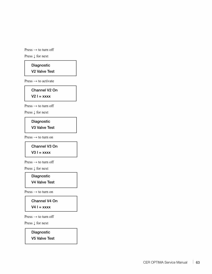
63CER OPTIMA Service Manual
Press → to turn off
Press ↓ for next
Diagnostic
V2 Valve Test
Press → to activate
Channel V2 On
V2 I = xxxx
Press → to turn off
Press ↓ for next
Diagnostic
V3 Valve Test
Press → to turn on
Channel V3 On
V3 I = xxxx
Press → to turn off
Press ↓ for next
Diagnostic
V4 Valve Test
Press → to turn on
Channel V4 On
V4 I = xxxx
Press → to turn off
Press ↓ for next
Diagnostic
V5 Valve Test
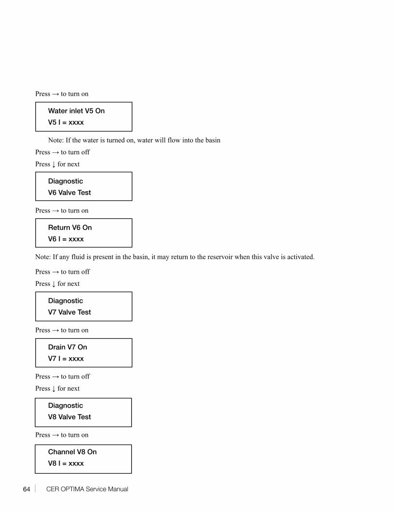
64 CER OPTIMA Service Manual
Press → to turn on
Water inlet V5 On
V5 I = xxxx
Note: If the water is turned on, water will flow into the basin
Press → to turn off
Press ↓ for next
Diagnostic
V6 Valve Test
Press → to turn on
Return V6 On
V6 I = xxxx
Note: If any fluid is present in the basin, it may return to the reservoir when this valve is activated.
Press → to turn off
Press ↓ for next
Diagnostic
V7 Valve Test
Press → to turn on
Drain V7 On
V7 I = xxxx
Press → to turn off
Press ↓ for next
Diagnostic
V8 Valve Test
Press → to turn on
Channel V8 On
V8 I = xxxx
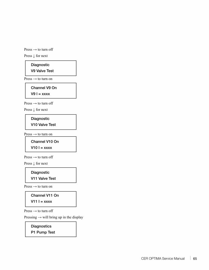
65CER OPTIMA Service Manual
Press → to turn off
Press ↓ for next
Diagnostic
V9 Valve Test
Press → to turn on
Channel V9 On
V9 I = xxxx
Press → to turn off
Press ↓ for next
Diagnostic
V10 Valve Test
Press → to turn on
Channel V10 On
V10 I = xxxx
Press → to turn off
Press ↓ for next
Diagnostic
V11 Valve Test
Press → to turn on
Channel V11 On
V11 I = xxxx
Press → to turn off
Pressing → will bring up in the display
Diagnostics
P1 Pump Test
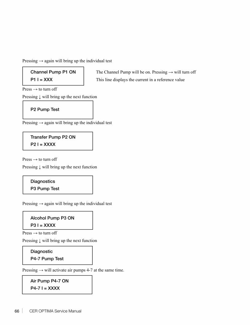
66 CER OPTIMA Service Manual
Pressing → again will bring up the individual test
Channel Pump P1 ON The Channel Pump will be on. Pressing → will turn off
P1 I = XXX This line displays the current in a reference value
Press → to turn off
Pressing ↓ will bring up the next function
P2 Pump Test
Pressing → again will bring up the individual test
Transfer Pump P2 ON
P2 I = XXXX
Press → to turn off
Pressing ↓ will bring up the next function
Diagnostics
P3 Pump Test
Pressing → again will bring up the individual test
Alcohol Pump P3 ON
P3 I = XXXX
Press → to turn off
Pressing ↓ will bring up the next function
Diagnostic
P4-7 Pump Test
Pressing → will activate air pumps 4-7 at the same time.
Air Pump P4-7 ON
P4-7 I = XXXX
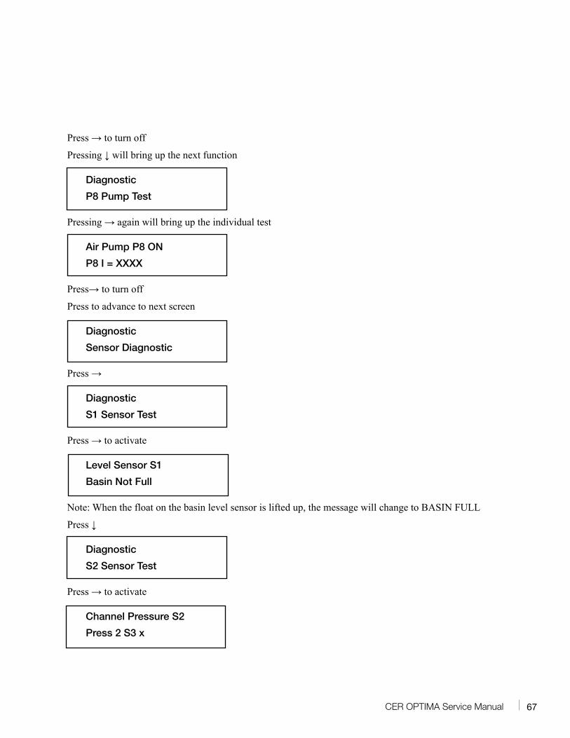
67CER OPTIMA Service Manual
Press → to turn off
Pressing ↓ will bring up the next function
Diagnostic
P8 Pump Test
Pressing → again will bring up the individual test
Air Pump P8 ON
P8 I = XXXX
Press→ to turn off
Press to advance to next screen
Diagnostic
Sensor Diagnostic
Press →
Diagnostic
S1 Sensor Test
Press → to activate
Level Sensor S1
Basin Not Full
Note: When the float on the basin level sensor is lifted up, the message will change to BASIN FULL
Press ↓
Diagnostic
S2 Sensor Test
Press → to activate
Channel Pressure S2
Press 2 S3 x
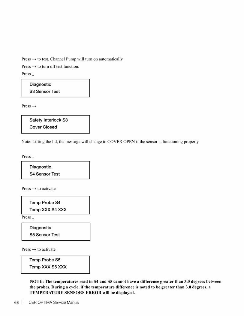
68 CER OPTIMA Service Manual
Press → to test. Channel Pump will turn on automatically.
Press → to turn off test function.
Press ↓
Diagnostic
S3 Sensor Test
Press →
Safety Interlock S3
Cover Closed
Note: Lifting the lid, the message will change to COVER OPEN if the sensor is functioning properly.
Press ↓
Diagnostic
S4 Sensor Test
Press → to activate
Temp Probe S4
Temp XXX S4 XXX
Press ↓
Diagnostic
S5 Sensor Test
Press → to activate
Temp Probe S5
Temp XXX S5 XXX
NOTE: The temperatures read in S4 and S5 cannot have a difference greater than 3.0 degrees between the probes. During a cycle, if the temperature difference is noted to be greater than 3.0 degrees, a TEMPERATURE SENSORS ERROR will be displayed.
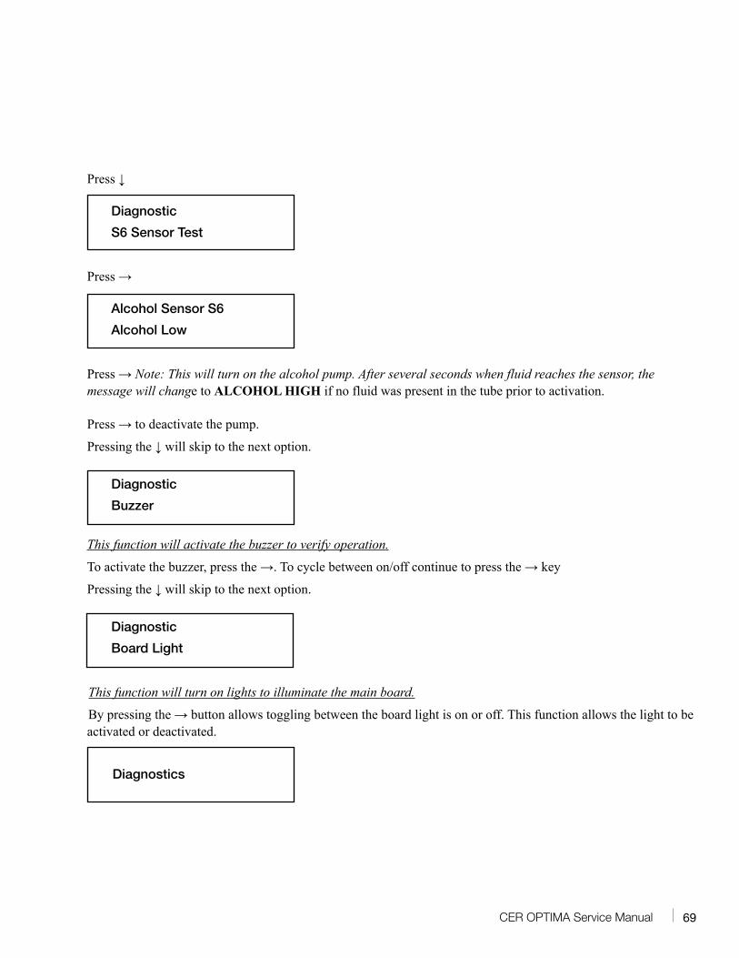
69CER OPTIMA Service Manual
Press ↓
Diagnostic
S6 Sensor Test
Press →
Alcohol Sensor S6
Alcohol Low
Press → Note: This will turn on the alcohol pump. After several seconds when fluid reaches the sensor, the message will change to ALCOHOL HIGH if no fluid was present in the tube prior to activation.
Press → to deactivate the pump.
Pressing the ↓ will skip to the next option.
Diagnostic
Buzzer
This function will activate the buzzer to verify operation.
To activate the buzzer, press the →. To cycle between on/off continue to press the → key
Pressing the ↓ will skip to the next option.
Diagnostic
Board Light
This function will turn on lights to illuminate the main board.
By pressing the → button allows toggling between the board light is on or off. This function allows the light to be activated or deactivated.
Diagnostics
70 CER OPTIMA Service Manual
By pressing Enter, the lights will remain illuminated until turned off in Diagnostics.
Pressing ↓ to skip to the next option.
Diagnostic
Show Version
The function will display the current firmware and software version.
Pressing → to display the software version.
Pressing the ↓ will skip to the next option.
Diagnostic
Calibration
This function is used to calibrate the channel pressure sensor. Proper test equipment is required to access this function.
Press and hold the → and then press ↓ to access the test procedure. Please consult technical service before accessing this function.
71CER OPTIMA Service Manual
Subject to the terms below, MEDIVATORS Inc. (the “Company”) warrants that its products (the “Products”) will conform to the Company’s written specifications (where applicable) and will be free from defects in material and workmanship under normal use and service for the following periods (the “Warranty Period”):
Endoscope reprocessors and associated equipment, and Irrigation Pumps: fifteen (15) months from date of shipment from the Company or one (1) year from the date of installation, whichever occurs first.
Consumables, accessories, and Product service parts, including, but not limited to, endoscope hook-ups, filters, printers, printer supplies, test strips, accessory bags, and service parts for products: ninety (90) days from the date of installation or one hundred and twenty (120) days from the date of shipment, whichever occurs first.
Disposable Products: warranted for single use. The Warranty Period will not in any case exceed the expiration date on the Product label.
The warranty does not cover, and the Company will have no warranty obligation whatsoever with respect to, any damage to a Product caused by or associated with: (i) external causes, including without limitation, accident, vandalism, acts-of-God, power failure or electric power surges, (ii) abuse, misuse or neglect of the Product by the customer or use of unauthorized third party filters or other consumables and accessories, (iii) usage not in accordance with product instructions, (iv) the customer’s failure to perform required preventive maintenance, or (v) servicing or repair not authorized by the Company.
Limitation of Remedy
The warranty obligation of the Company hereunder is limited to (at its option) (i) the repair or replacement of the defective Products or any parts it deems defective, or (ii) a refund of the purchase price. This will be customer’s exclusive remedy for a covered defect.
In order to recover under the warranty, the customer must notify the Company in the state (if in the U.S.A.) or the country of installation, of the defect (describing the problem in reasonable detail) prior to the expiration of the Warranty Period and within thirty (30) days of discovery of the defect. Upon receiving the Company’s official “Returned Material Authorization” (RMA), the customer must promptly return the defective part or Product to the Company (or the service center indicated on the RMA), freight and insurance prepaid. The Company will not be responsible for any damage during shipment.
Warranty Disclaimer
THE WARRANTY ABOVE IS THE COMPANY’S ENTIRE WARRANTY OBLIGATION TO THE PURCHASER OF PRODUCTS. IT IS IN LIEU OF ALL OTHER WARRANTIES OF THE COMPANY, EXPRESS OR IMPLIED, INCLUDING, WITHOUT LIMITATION, WARRANTY OF MERCHANTABILITY OR FITNESS FOR A PARTICULAR PURPOSE, AND THE COMPANY DOES NOT REPRESENT OR WARRANT THAT ANY PRODUCT WILL MEET CUSTOMER’S REQUIREMENTS. THE COMPANY’S RESPONSIBILITY FOR DEFECTS IN A PRODUCT IS LIMITED SOLELY TO REPAIR, REPLACEMENT OR REFUND OF THE PURCHASE PRICE AS SET FORTH IN THIS WARRANTY STATEMENT.
TO THE EXTENT PERMITTED BY LAW, THE COMPANY SHALL NOT, UNDER ANY CIRCUMSTANCES, BE LIABLE TO CUSTOMER FOR CONSEQUENTIAL, INCIDENTAL, INDIRECT, PUNITIVE OR SPECIAL DAMAGES OR LOSSES, INCLUDING WITHOUT LIMITATION, DAMAGES ARISING OUT OF OR IN CONNECTION WITH ANY MALFUNCTIONS, DELAYS, LOSS OF PROFIT, INTERRUPTION OF SERVICE, OR LOSS OF BUSINESS OR ANTICIPATORY PROFITS, EVEN IF THE COMPANY HAS BEEN APPRISED OF THE LIKELIHOOD OF SUCH DAMAGES OCCURRING.
This Warranty gives the customer of Products specific legal rights, and customers may also have other rights which vary from jurisdiction to jurisdiction.
In no event shall the Company’s liability exceed the original purchase price of the covered Product.
No representative or agent of the Company has any authority to bind the Company to any other representation or warranty with respect to the Products, and the customer accepts the Products subject to all of the terms above.

72 CER OPTIMA Service Manualwww.medivators.com
Manufactured in the USA by:
MEDIVATORS Inc. Headquarters14605 28th Avenue NorthMinneapolis, MN 55447 USAToll Free: +1.800.444.4729
MEDIVATORS BVSourethweg 116422PC HeerlenThe NetherlandsTel: +31.45.5.471.471
MEDIVATORS Asia/Paci�c Pte Ltd1A International Business Park#05-01 Singapore 609933Tel: +65.6227.9698
MEDIVATORS Beijing Representative Of�ceRoom 708, 7th Floor Kaiheng Center, Block BNo. 2 Chaoyangmennei StreetDongcheng District, Beijing China 100010Tel: +8610.6567.8446