Embed Size (px)
Citation preview
Equipment Issue B030-101522 Rev. C, September 2005
Section 311-610-20B
0509IBRC
Page 1 of 26Copyright 2005 Westell, Inc. All rights reserved. Printed in the United States of America. *CLEI is a trademark of Telcordia Technologies. 200 MECHANICS in a registered trademark of Westell, Inc.
DS1 Network Interface Unit with Performance MonitoringModel 3116-10 Issue BPart of the Westell PROACT Family
CLEI* Code: T1L8AC0AAA
CONTENTS PAGE #
1. GENERAL 1. . . . . . . . . . . . . . . . . . . . . . . . . . . . . . . . . . . .
2. APPLICATIONS 2. . . . . . . . . . . . . . . . . . . . . . . . . . . . . . .
3. TRANSMISSION FEATURES AND OPTIONS 3. . . . .
4. LOOPBACK FEATURES AND OPTIONS 5. . . . . . . . .
5. SECTIONALIZATION ALARM FEATURES 7. . . . . . .
6. PERFORMANCE MONITORING & REPORTING 8.
7. HARDWARE OPTIONS & FEATURES 9. . . . . . . . . . .
8. INSTALLATION 11. . . . . . . . . . . . . . . . . . . . . . . . . . . . . .
9. SET-UP AND OPERATION 13. . . . . . . . . . . . . . . . . . . .
10. TESTING & TROUBLESHOOTING 21. . . . . . . . . . . . .
11. CUSTOMER & TECHNICAL SERVICES 21. . . . . . . .
12. WARRANTY & REPAIRS 21. . . . . . . . . . . . . . . . . . . . . .
13. SPECIFICATIONS 22. . . . . . . . . . . . . . . . . . . . . . . . . . . .
1. GENERAL
1.1 Document Purpose
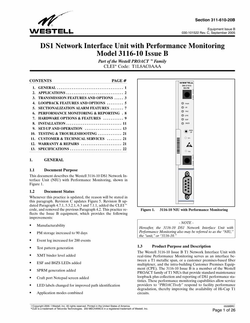
This document describes the Westell 3116-10 DS1 Network In-terface Unit (NIU) with Performance Monitoring, shown inFigure 1.
1.2 Document Status
Whenever this practice is updated, the reason will be stated inthis paragraph. Revision C updates Figure 5. Revision B up-dated Paragraph 4.7.1, 5.3.2.1, 6.3 and 7.1.1, added the CLEIcode, and removed the previous Paragraph 4.2. This practice re-flects the Issue B equipment, which provides the followingimprovements:
Manufacturability
PM storage increased to 90 days
Event log increased for 200 events
Test pattern generation
XMT binder level added
ESF and B8ZS LEDs added
SPRM generation added
Craft port Notepad screen added
LED labels changed for improved path identification
Application modes combined
Figure 1. 3116-10 NIU with Performance Monitoring
B90-311610
125641
NIU-PM
PWR
ESF
FAC
CPE
LB
CPE BRG
TP1
TP2
MANLB
B8ZS
FAC BRG
- NOTE -
Hereafter, the 3116-10 DS1 Network Interface Unit withPerformance Monitoring also may be referred to as the NIU,"the unit," or 3116-10."
1.3 Product Purpose and Description
The Westell 3116-10 Issue B T1 Network Interface Unit withreal-time Performance Monitoring serves as an interface be-tween a T1 metallic span, or a customer premises-based fibermultiplexer, and the intra-building Customer Premises Equip-ment (CPE). The 3116-10 Issue B is a member of the WestellPROACT family of T1 NIUs that provide standard maintenanceloopback plus collection and reporting of DS1 performance sta-tistics. These performance monitoring capabilities allow serviceproviders to PROACTively" respond to facility performancedegradation, thereby improving the availability of Hi-Cap T1circuits.
Section 311-610-20B 030-101522 Rev. C
2 0509IBRC
1.4 Product Mounting
The 3116-10 is a 200 MECHANICS NIU and makes electricalconnections to the Facility and CPE sides of the circuit througha 56-pin card-edge connector of a 200- or 400-mechanics typemounting, using industry-standard pin assignments. The mount-ing assembly is usually mounted on an equipment backboard atthe customer location, after the building entrance terminal andprimary protection. Westell offers a wide range of single andmultiple slot mountings available in both backboard (wall) andrack mount versions for NIUs. In some applications it may be de-sirable to situate the NIU in outside plant cabinets or enclosures.The NIU is fully qualified for operating over the temperaturerange of -40 to +65°C (temperature hardened).
1.5 Product Features
The 3116-10 offers the following features.
Full-featured T1 NIU loopback device plus detailed T1 per-formance monitoring and reporting at the customer facilityinterface
Loopback activation and deactivation using inband (un-framed or SF/ESF framed) or ESF Data Link codes
Addressed loopback control with 16-bit pattern for TER(T1 Extension Repeater) applications
CPE-to-Facility LBO provisionable from 0 to 22.5dB in 7.5dB increments
Alternate self-aligning CPE-to-Facility LBO that automati-cally protects the network from a mis-optioned customerLBO
Enhanced sectionalization capabilities via AIS-CI andRAI-CI alarm signals as defined by T1.403-1998
Derives and maintains DS1 performance statistics inde-pendently for each direction of transmission
Supports both 90-day stored as well as real-time perfor-mance reporting modes
Flexible DS1 performance reporting options:
Local, non-intrusive access to PM parameters via afront-panel local craft interface port
Remote, intrusive access during loopback to PM pa-rameters via TL1 commands and responses in the ESFData Link
Remote, non-intrusive access to PM parameters viaTL1 commands and responses in the Data Link, by useof a Test Head, without affecting customer payload
Remote, non-intrusive real-time reporting of PM pa-rameters via 1-second NPRM or SPRM reports in theData Link per ANSI T1.403-1998
On board test pattern generator
Notepad craft screen for documenting information aboutthe circuit
User-configurable alarm threshold craft screen
Integral real-time clock provides time stamping of all per-formance information
Selectable powering option (via jumper option) for span orlocal power
Front-panel test points for measuring span current
Bridge-type bantam jacks on FAC IN and FAC OUT portsfor transmission path monitoring
Front-panel craft interface port (serial RS-232, VT-100) forlocal, non-intrusive PM extraction, unit set up, test codegeneration and circuit maintenance
Remote provisioning and query of options (TL1 non-intru-sive or 16-bit intrusive)
Front-panel LEDs indicate status of:
PWR (Power)
LB (Loopback)
FAC (Facility Signal Status)
CPE (CPE Signal Status)
ESF (ESF Framing detected from the facility)
B8ZS (B8ZS detected from the facility)
Internal per-circuit local power fusing
Certified to UL standard 60950
Recognized to CAN/CSA-C22.2 No. 60950-00
NEBS compliant
Operates over the -40 to +65C temperature range allow-ing deployment in outside plant (OSP) enclosures andcabinets; Temperature Hardened
2. APPLICATIONS
The NIU can be used to terminate a T1 metallic span facility oras an adjunct to a lightwave multiplexer when DS1 circuits areextended to a customer location on fiber facilities. The CPE con-nections are intra-building.
The unit is situated at the customer’s premises and functions asa maintenance interface between the T1 metallic span or fibermultiplexer facility and the CPE. In addition to conventionalNIU functions such as loopback, the NIU collects performancedata for both directions of the facility, stores the information andreports it to the remote test center either on demand via TL1commands or on a real-time basis via NPRMs or SPRMs. Thisperformance information can also be locally accessed via thefront-panel RS-232 craft interface port.
- NOTE -
Real-time Performance Monitoring retrieval will initially requirethat the test head be updated to monitor the Facility Data Linknon-intrusively for performance information.
2.1 Transmission Design
2.1.1 T1 Span - Copper Applications
2.1.1.1 Normal T1 span design allows from 0 to 15dB of lossfrom the last repeater in the span to the customer interface and

Section 311-610-20B
030-101522 Rev. C
30509IBRC
a maximum loss of 7.5dB for inside wiring to the CPE (seeFigure 2). This represents a total loss of 22.5dB. This mode pro-vides a receive transmission path that can be configured to passthe signal from the span to the CPE with either no net regenera-tion or with the optional regenerator to 0dB DSX. The optionalregenerator in this path can be used in applications where themaximum loss of 22.5dB to the CPE cannot be achieved other-wise, or in special situations where the customer requires a 0dBDSX handoff.
2.1.1.2 The unit’s transmit path from the CPE to the Networkprovides a selectable 0 to 22.5 dB LBO as well as an automatic,self-aligning LBO (Line Build Out) circuit to meet route junc-tion and end section design requirements in T1 spanapplications.
2.1.2 T1 Fiber Applications
When T1 service to a customer is provided via fiber, the unit canbe configured to serve as a maintenance interface between thefiber mux and the CPE. The unit can be located up to 220 feetfrom the mux. See Figure 3. In this mode, the unit can be provi-sioned for CPE-to-FAC regeneration which will regenerateCPE input levels that have been attenuated from 0 to 30dB to anormal 0dB DSX. This is useful due to the fact that the DS1 low-speed tributary ports of most multiplexers are designed toaccommodate input levels that have been attenuated no morethan 3dB from 0dB DSX. This feature allows for greater sectionlosses to be accommodated. The CPE-to-FAC regeneration fea-ture allows the unit to be used in applications that previouslyrequired a T1 Extension Repeater.
2.2 Power
2.2.1 Local Power
The NIU can be powered either from the T1 span or from a localexternal supply. When locally powered, the supply should be 22
to 56Vdc and can be either a positive or negative ground refer-ence. This allows the NIU to operate from +24Vdc supplies atcertain wireless and PCS (Personal Communication Service)sites. In the local power mode, the NIU completes the T1 spansimplex power loop and drops negligible span voltage.
2.2.2 Span Power
When optioned for Span Power, the unit is powered remotelyfrom the last serving office via the transmission simplex leads.The unit will operate with a simplex current ranging from 57 to63 mA and will drop 24 Volts nominal at 60mA. In addition, inthe Span Power, the unit will serve as a termination device forspan power by looping the simplex current back on the FACOUT simplex lead.
3. TRANSMISSION FEATURES & OPTIONS
The NIU can be configured to operate in multiple applications.The specific transmission provisioning is dependent on the ap-plication. To facilitate this discussion, refer to Figure 4 for asimplified diagram of the NIU transmission path during normaloperation.
3.1 RCV Path: Facility to CPE (A to Z Direction)
3.1.1 The incoming DS1 bit stream from the facility entersthe NIU on the FAC IN port and is transformer coupled into thereceive path circuitry. To facilitate circuit testing, a front-panelbantam jack (FAC BRG) provides bridge access to the receivepath.
3.1.2 The FAC-to-CPE path is continuously monitored forloss of signal, control codes and performance statistics by vari-ous detectors that operate over an input signal range of 0 to-30dB DSX, and are unaffected by cable length or terminationson any port or signal state of the CPE. If the FAC IN signal con-tains more than 128 consecutive zeros, a FAC-to-CPE pathLoss-Of-Signal condition is declared, the front-panel FAC LEDlights solid red and an Alarm Indication Signal (AIS) is sent tothe CPE.
Figure 2. Metallic T1 Span Applications
CPE
15dB 7.5dB
22.5dB
NetworkInterface
NIULINERPTR
Figure 3. Lightwave/Mux Fiber Applications
CPE
15dB 7.5dB
22.5dB
NetworkInterface
MUX
NIU
LBO
220 feet

Section 311-610-20B 030-101522 Rev. C
4 0509IBRC
5
15
CT1
CR1
7
13
41
47
55
49
CT
CR
FACIN
FACOUT
CPEIN
CPEOUT
T
R
T1
R1
Figure 4. 3116-10 Block Diagram Overview
FACBRG
TO/FROMTELCO
FACILITY
DIS
CPEBRG
FAC
PERFORMANCEMONITOR & LOS
DETECTOR(CPE-to-FAC PATH - Z-A)
PERFORMANCEMONITOR & LOS
DETECTOR(FAC-to-CPE PATH - A-Z)
PERFORMANCEREGISTERS
Note: Switches shown are for illustrative purposesonly - options are provisioned electronically
CONTROL CODEDETECTORS
FAC-to-CPEREGEN
TO/FROMCUSTOMERINTERFACE
(CPE)
CPE
CPE-to-FACREGEN
EN
DIS
EN
Provisionable/Self-Aligning
LBO
22.5 dB
15 dB
0 dB7.5 dB
AB15 dBAB22.5 dB
Figure 5. 3116-10 Detailed Block Diagram
FAC-to-CPERegen
DIS
EN
17
5
15
55
49
CT1
CR1
CPE Out
CT
CR
CPE In
7
13
T
R
TP1
TP2
GND
P201 SPAN
LOCAL SPAN
P201
LOCAL
T1
R1
41
47
PWR
LB
FAC Out
FACBRG
SystemController AndPM Registers
Provisionable/Self-Aligning
LBO
LBRelay
10 Ω
LB
LB
CPEBRG
PowerConverter
LOCAL SPAN
P201
TO CPE
FROM CPE
TOFACILITY
FROMFACILITY
FAC In
35
MANLB
LB1
LB1
LB1Relay
NetworkLoopback
CPELoopback
ESF B8ZS
CPE-to-FACRegen
22.5 dB
15 dB
27FRM GND
-V
OV
ER
CU
RR
EN
TP
RO
TE
CT
ION
Control CodeDetector
PerformanceMonitor &
LOS Detector
FACAIS to CPEGenerator
LB
CPE LOS(LB/AIS/Idle/RAI-CI)
Generator
0 dB7.5 dB
AB15 dBAB22.5 dB
OV
ER
CU
RR
EN
TP
RO
TE
CT
ION DIS
ENPerformance
Monitor &LOS Detector
CPE
DB-9Craft Port
Section 311-610-20B
030-101522 Rev. C
50509IBRC
3.1.3 FAC-to-CPE Regen
With FAC-to-CPE Regen enabled, the NIU will regenerate in-put levels that have been attenuated from 0 to 30dB to a nominal0dB DSX to the customer interface. The FAC-to-CPE Regen isa selectable option that can be set remotely via TL1 or 16-bitcommands or locally via the craft terminal interface port. Withthe FAC-to-CPE Regen disabled, the receive transmission pathprovides no net regeneration from input to output. In this case,the NIU has a nominal insertion loss of 1.5dB.
3.2 XMT Path: CPE-to-FAC (Z to A Direction)
The DS1 signal from the CPE enters the NIU via the CPE INport and is transformer coupled into the transmit path circuitry.The transmit path is continuously monitored for loss of signaland DS1 performance from the customer. If the CPE IN signalcontains more than 128 consecutive zeros, a CPE-to-FAC pathLoss-Of-Signal condition is declared and the front-panel CPELED lights solid red.
3.2.1 CPE-to-FAC Regen
When placed behind a multiplexer (i.e., fiber applications), theunit functions as a T1 Extension Repeater and requires the CPE-to-FAC Regen to be enabled. With FAC Regen enabled, theNIU will regenerate input levels that have been attenuated from0 to 30dB to a nominal 0dB DSX to the facility interface. TheCPE-to-FAC Regen is a selectable option that can be set re-motely via TL1 or 16-bit commands or locally via the craftterminal interface port. With the CPE-to-FAC Regen disabled,the receive transmission path provides no net regeneration frominput to output. In this case, the signal is connected directly tothe CPE-to-FAC LBO circuit.
3.2.2 CPE-to-FAC LBO
3.2.2.1 LBO (Line Build Out) is an artificial line used to meetT1 span and end-section design requirements. The 3116-10 pro-vides a fixed LBO circuit as well as a self aligning LBO circuit.
3.2.2.2 The fixed LBO circuit provides from 0 to 22.5dB of sig-nal attenuation in 7.5dB increments. The CPE-to-FAC LBO isa selectable option that can be set remotely via TL1 or 16-bitcommands or locally via the craft terminal interface port.
3.2.2.3 As an alternative to the fixed LBO settings, the "Auto-Binder" feature can be selected (AB15 and AB22.5). Theauto-binder option only introduces loss when necessary, auto-matically protecting the network from mis-optioned customerequipment - specifically, mis-optioned customer LBO settings.
3.2.2.4 At installation, the NIU/PM will have it’s "Auto-Bind-er Level" circuitry optioned to match the circuit’s binder levelrequirement .... e.g. -22.5 dB (AB22.5). The "Auto-binder Lev-el" circuitry measures the signal level arriving from the facilityas well as the signal level arriving from the customer. Based onthese levels, the NIU/PM’s "Auto-Binder Level" circuitry willautomatically insert the appropriate amount of additional lossrequired to ensure the customer’s signal arrives at the bindergroup’s common termination point at the correct level. For a set-ting of "AB22.5", a level of -22.5 dB is maintained. The"Auto-binder Level" circuitry constantly monitors the input lev-els from the network and customer and adjusts how muchadditional LBO is required to keep the binder level at the neces-sary level.
- NOTE -
The Auto-Binder Level" circuitry only introduces additionalloss when the customer fails" to meet the signal level require-ments set forth by the RBOC. The additional loss is only insertedwhen the customer’s signal threatens to interfere with other, adja-cent T1 service by introducing crosstalk problems. Additionally,sufficient hysteresis is provided to prevent the Auto-Binder" cir-cuitry from oscillating in and out.
Examples:
If FAC IN level is 0dB and CPE IN level is 22.5dB, andBinder Level selection is set for 22.5dB, the LBO circuitwould adjust itself to 0dB.
If FAC IN level is 0dB and CPE IN level is 15dB, and theBinder Level selection is set for 22.5dB, the LBO circuitwould adjust itself to 7.5dB.
3.2.2.5 The resulting signal is then output over the FAC OUTport toward the Telco Facility. To facilitate circuit testing, afront-panel bantam jack (CPE BRG) provides bridging access tothe path.
3.3 Monitored Line Coding - AMI/B8ZS
The Monitored Line Code option determines if B8ZS octets and8 consecutive 0’s are reflected in the Line Errored Seconds andB8ZS Errored Second performance parameters. This optiondoes not effect the unit’s transmission path. When the Moni-tored Line Coding is set for AMI, occurrences of 16 consecutive0’s will be disregarded and occurrences of B8ZS octets will be re-flected in the B8ZS Errored Count. When the Monitored LineCoding is set for B8ZS, occurrences of B8ZS octets will be disre-garded and occurrences of 8 consecutive 0’s will be reflected inthe Line Errored Seconds.
3.4 Monitored Framing - ESF/SF
The Monitored Framing option determines the framing refer-ence that the performance monitoring (PM) section of the NIUwill use in it’s PM calculations. If the option is set for "ESF", val-id ESF-framing bits and CRC-bits are expected. Note, thesetting of this option does not affect the unit’s ability to pass sig-nal. That is, if this option is set to "SF", the NIU shall still havethe ability to pass ESF framed signals AND inject NPRM’s intothe ESF data-link - despite the fact that the PM section will bereporting Severe Errored Frame events due to the framing mis-match (i.e. Monitored Framing = SF, Actual FACILITYFraming = ESF). This option can be set remotely via TL1 or16-bit commands or locally via the craft interface.
4. LOOPBACK FEATURES AND OPTIONS
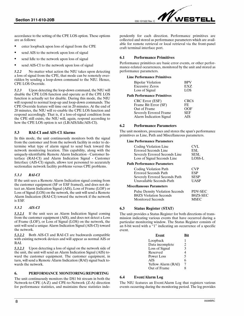
Loopback can be used during maintenance and circuit trouble-shooting to verify the integrity of the Telco DS1 facility up to, andincluding, the NIU. Loopback, when activated, loops the entireDS1 payload from the receive facility back towards the transmitfacility. Also, when the unit is in loopback the front-panel Loop-back LED (LB) will be on, and a loopback timeout circuit, ifenabled, is activated. Figure 6 shows a simplified view of the cir-cuit during loopback .
4.1 Facility Loopback
During Facility Loopback, the LB LED is solid yellow and thereceive T1 bit stream from the facility enters the NIU on theFAC IN port. The signal is then routed through the loopback

Section 311-610-20B 030-101522 Rev. C
6 0509IBRC
path to the opposite path and is passed back to the network viathe FAC OUT port. During Network-side Loopback, AIS is senttoward the CPE.
4.2 Dual Loopback
Dual Loopback is available to simultaneously loop back signalsto the facility and back to the CPE. Dual Loopback can be acti-vated via inband codes, via the MLB front panel switch, and viathe NIU craft port STATUS menu. When Dual Loopback is acti-vated, the LB LED is blinking yellow.
4.3 Loopback Activation/Deactivation
Loopback can be activated/deactivated by one of four ways:
1. Remotely, on-demand, via control codes (inband or ESFData Link) in the DS1 signal from a network test location,
2. Locally, on demand, via the front-panel MAN LB push but-ton switch,
3. Locally, on demand, via the front-panel RS-232 craft termi-nal interface port, or
4. Automatically, when the NIU detects a loss of signal fromthe CPE and CPE LOS response is optioned for LB (seePart 5).
4.4 Remote Loopback Activation/Deactivation
Loopback activation/deactivation is done from a remote testcenter, such as a Hi-Cap Center or Central Office, by sending in-band or ESF Data Link loopback control codes toward the NIUfor the proper duration. These control code sequences are listedin Table 1.
4.4.1 Inband Codes
Inband codes are repetitive patterns at the 1.544Mb rate andmay be unframed, SF framed or ESF framed. The Inband codepattern must be sent for a minimum of five seconds. The unit willreject the pattern if it is less than five seconds in duration or ifthe error rate is greater than 10-3.
4.4.2 ESF Codes
ESF codes are bit-oriented messages sent in the ESF Data Linkand must be sent for a minimum of four consecutive repetitions(approximately 16ms). The unit will reject the pattern if it is lessthan four consecutive repetitions in duration or if the error rateis greater than 10-3.
Function Code Type
DS1/T1 Activate 11000 Unframed, SF or ESF
(Loop Up) 0001 0010 1111 1111 ESF DATA LINK1
DS1/T1
D i
11100 Unframed, SF or ESF
Deactivate
(Loop Down)0010 0100 1111 1111
or 0011 1000 1111 1111
ESF DATA LINK1
Addressed LB
Activate
1101 0011 1101 0011(D3D3)
SF or ESF
Note 1: Right-most bit sent first.
Table 1. Loopback Control Codes
4.5 Addressed Loopback Mode
4.5.1 When installed in SONET/Mux applications, the NIUcan be configured for addressed loopbacks. This allows the craftto test locations at the service interface (SI) then subsequentlyloop the NIU adjacent to the SONET or Mux Interface. The ad-dressed loopback mode is an option that can be set remotely viaTL1 or 16-bit commands or locally via the craft interface port.
4.5.2 To loop back the unit when it is configured for ad-dressed loopback operation, the test person first sends theinband or ESF Data Link Loop-Up command (see Table 1) forthe proper duration. This will serve as an arming code for the3116-10. When the unit is armed, the LB LED will flash yellowat approximately 10 times per second.
4.5.3 The test person then sends the 16-bit repeating pattern1101 0011 1101 0011 for five seconds minimum. Upon receivingthe code, the unit enters loopback and 15 seconds later returnsan acknowledgement of 232 bit errors indicating the NIU islooped.
5
15
CT1
CR1
7
13
41
47
55
49
CT
CR
FACIN
FACOUT
CPEIN
CPEOUT
T
R
T1
R1
Figure 6. Transmission Path During Loopback Operation
FACBRG
TO/FROMTELCO
FACILITY
CPEBRG
FAC
LOS DETECTOR(CPE-to-FAC PATH - Z-A)
LOS DETECTOR(FAC-to-CPE PATH - A-Z)
AISGENERATOR
Note: Switches shown are for illustrative purposesonly - options are provisioned electronically
DIS
EN
FAC-to-CPEREGEN
TO/FROMCUSTOMERINTERFACE
(CPE)
CPE
CONTROL CODE
DETECTORS
X CPELoopback
CPE-to-FACREGEN
DIS
EN
Provisionable/Self-Aligning
LBO
22.5 dB
15 dB
0 dB7.5 dB
AB15 dBAB22.5 dB

Section 311-610-20B
030-101522 Rev. C
70509IBRC
4.6 Manual Loopback
The NIU loopback state can be controlled by pressing the front-panel MAN LB push button. Depression of the MAN LB pushbutton will cycle through the loopback states.
If depressed for 3 to 5 seconds, the LB LED will be on solid(yellow). If released in this interval, the Network Loopbackwill be activated.
If depressed for greater than 5 seconds, the LB LED will be-gin blinking (yellow) at approximately 1 time per second. Ifreleased after 5 seconds, the Dual Loopback will be acti-vated.
When first depressed, the LB LED will go off and remainoff during the first 3 seconds that the MAN LB is depressed.If released during this 3 second period, all existing loopbackconditions will be deactivated.
4.7 Loopback Time-out
4.7.1 The 3116-10 provides a selectable loopback time-outfeature that can be configured to release a code-activated loop-back condition either 20, 60, or 120 minutes or 24 hours afterinitial activation.
4.7.2 The loopback condition can be released before thetimeout expiration period by: 1) sending loop-down code to theNIU from the network test location, 2) through the craft inter-face port, or 3) by pressing the front-panel MAN LB switch forless than 3 seconds. Loopback timeout can be permanently dis-abled via an option provisioned locally from the craft interfaceport or remotely from the network test location.
4.8 CPE (Dual) Loopback Activation
4.8.1 To activate CPE loopback, the unit must first be in net-work-side loopback from the remote test location. At this point,re-application of loop-up code will operate CPE loopback allow-ing the customer or craft personnel to evaluate the integrity ofthe circuitry on the CPE-side of the demarcation point. The unitcan be placed in CPE loopback via the front-panel MAN LBpush button (see Paragraph 4.6). CPE Loopback can also be ac-tivated and deactivated from the Circuit Status Menu via thecraft interface port.
4.8.2 When CPE loopback is activated, it will remain acti-vated until:
1. the NIU detects a loop-down command from the Network-side,
2. when the timeout release feature expires,
3. when released via the craft interface port, or
4. when the MAN LB switch is pressed.
5. SECTIONALIZATION ALARM FEATURES
The NIU is equipped with features that allow a network moni-toring location to differentiate between fault conditions that arebeyond the NIU (i.e., CPE or inside wiring) and those that arelegitimate network problems.
5.1 CPE LOS Modes
5.1.1 LB Upon CPE LOS
In this mode, the unit continuously monitors the DS1 signalfrom the CPE for customer loss of signal, and upon detecting aloss will change the CPE LED to red and cause the unit to enterLoopback toward the network. When the signal from the CPEis restored the unit will return to normal operation. LB uponCPE LOS is an option that can be set remotely via TL1 or 16-bitcommands or locally via the craft interface port. When set to en-ter loopback upon detecting a loss of signal from the CPE, theNIU will assume the transmission path as shown in Figure 6.
5.1.2 AIS Upon CPE LOS
In this mode, the unit continuously monitors the DS1 signalfrom the CPE for customer loss of signal, and upon detecting aloss will change the CPE LED to red and send an unframed, all-ones Alarm Indication Signal (AIS) to the network. When thesignal from the CPE is restored the unit will return to normal op-eration. The AIS upon CPE LOS mode is an option that can beset remotely via TL1 or 16-bit commands or locally via the craftinterface port.
5.1.3 Idle Code Upon CPE LOS
In this mode, the unit continuously monitors the DS1 signalfrom the CPE for customer loss of signal and upon detecting aloss will change the CPE LED to red and send an Idle code to-ward the network. When signal from the customer is restored,the NIU returns to normal operation. The specific format inwhich the Idle signal is sent toward the network facility is depen-dent on the format of the DS1 signal received from the networkfacility:
1. If the received signal is SF, the Idle signal will be SF and willprovide a 0001 0111 repeating pattern in each of the 24 DS0time slots,
2. If the received signal is ESF, the Idle signal will be ESF andprovide a 0001 0111 repeating pattern in each of the 24 DS0time slots. In addition, the ESF Data Link will contain theESF yellow alarm signal 1111 1111 0000 0000, interruptedeach second with a 100ms burst of LAPD idle code 01111110,
3. If no signal is received from the network or if the DS1 signalis unframed, the NIU will default to the SF Idle mode.
The Idle Code upon CPE LOS mode is an option that can be setremotely or locally via TL1 or 16-bit commands or via the craftinterface port.
5.1.4 AIS-CI Upon CPE LOS
In this mode, the unit continuously monitors the DS1 signalfrom the CPE for customer loss of signal, and upon detecting aloss will change the CPE LED to red and send an AIS-CI patterntoward the network. When signal from the customer is restored,the unit returns to normal operation. The AIS-CI upon CPELOS mode is an option that can be set remotely via TL1 16-bitcommands or locally via the craft interface port.
5.2 CPE LOS Override
5.2.1 When the NIU detects a loss of signal from the CPEand if the CPE LOS option is enabled, the NIU will respond in
Section 311-610-20B 030-101522 Rev. C
8 0509IBRC
accordance to the setting of the CPE LOS option. These optionsare as follows:
enter loopback upon loss of signal from the CPE
send AIS to the network upon loss of signal
send Idle to the network upon loss of signal
send AIS-CI to the network upon loss of signal
5.2.2 No matter what action the NIU takes upon detectinga loss of signal from the CPE, that mode can be remotely over-ridden by sending a loop-down command to the NIU. Hence,CPE LOS Override.
5.2.3 Upon detecting the loop-down command, the NIU willdisable the CPE LOS function and operate as if the CPE LOSfunction is actually set for disable. During this mode, the NIUwill respond to normal loop-up and loop-down commands. TheCPE Override feature will time out in 20 minutes. At the end of20 minutes, the NIU will re-enable the CPE LOS function andrespond accordingly. That is, if a loss-of-signal condition fromthe CPE still exists, the NIU will, again, respond according tohow the CPE LOS option is set (LB/AIS/Idle/AIS-CI).
5.3 RAI-CI and AIS-CI Alarms
In this mode, the unit continuously monitors both the signalfrom the customer and from the network facility in order to de-termine what type of alarm signal to send back toward thenetwork monitoring location. This capability, along with theuniquely-identifiable Remote Alarm Indication - Customer In-terface (RAI-CI) and Alarm Indication Signal - CustomerInterface (AIS-CI) signals, allows test personnel to accuratelysectionalize network facility problems versus CPE problems.
5.3.1 RAI-CI
If the unit sees a Remote Alarm Indication signal coming fromthe customer equipment (SF or ESF framed), and does not de-tect an Alarm Indication Signal (AIS), Loss of Frame (LOF) orLoss of Signal (LOS) on the network, the unit will send a RemoteAlarm Indication (RAI-CI) toward the network if the networkis ESF.
5.3.2 AIS-CI
5.3.2.1 If the unit sees an Alarm Indication Signal comingfrom the customer equipment (AIS), and does not detect a Lossof Frame (LOF), or Loss of Signal (LOS) on the network, theunit will send a unique Alarm Indication Signal (AIS-CI) towardthe network.
5.3.2.2 Both AIS-CI and RAI-CI are backwards compatiblewith existing network devices and will appear as normal AIS orRAI.
5.3.2.3 Upon detecting a loss of signal on the network side ofthe unit, the unit will send an Alarm Indication Signal (AIS) to-ward the customer equipment. The customer equipment, inturn, will send a Remote AIarm Indication (RAI) signal back to-wards the network.
6. PERFORMANCE MONITORING/REPORTING
The unit continuously monitors the DS1 bit stream in both theNetwork-to-CPE (A-Z) and CPE-to-Network (Z-A) directionfor performance statistics, and maintains these statistics inde-
pendently for each direction. Performance primitives arecollected and stored as performance parameters which are avail-able for remote retrieval or local retrieval via the front-panelcraft terminal interface port.
6.1 Performance Primitives
Performance primitives are basic error events, or other perfor-mance-related occurrences, monitored by the unit and stored asperformance parameters.
Line Performance Primitives
Bipolar Violation BPVExcessive Zeros EXZLoss of Signal LOS
Path Performance Primitives
CRC Error (ESF) CRC6Frame Bit Error (SF) FEOut of Frame OOFSeverely Errored Frame SEFAlarm Indication Signal AIS
6.2 Performance Parameters
The unit monitors, processes and stores the span’s performanceprimitives as Line, Path and Miscellaneous parameters.
Line Performance Parameters
Coding Violation Line CVLErrored Seconds Line ESLSeverely Errored Seconds Line SESLLoss of Signal Seconds Line LOSS-L
Path Performance Parameters
Coding Violation Path CVPErrored Seconds Path ESPSeverely Errored Seconds Path SESPUnavailable Seconds-Path UASP
Miscellaneous Parameters
Pulse Density Violation Seconds PDV-SECB8ZS Violation Seconds B8ZS-SECMonitored Seconds MSEC
6.3 Status Register (STAT)
The unit provides a Status Register for both directions of trans-mission indicating various events that have occurred during aparticular monitoring window. The Status Register consists ofan 8-bit word with a 1" indicating an occurrence of a specificevent.
Event Bit
Loopback 1Data incomplete 2Loss of Signal 3Reserved 4Power Loss 5AIS 6Yellow Alarm (RAI) 7Out of Frame 8
6.4 Event/Alarm Log
The NIU features an Event/Alarm Log that registers variousevents occurring during the monitoring period. The log provides

Section 311-610-20B
030-101522 Rev. C
90509IBRC
time-stamped entries for the most important types of eventssuch as loss of signal, power outages, PM registers cleared, alarmdetection, and more. Several different types of events are pos-sible in the log as listed in the examples of Table 2. TheEvent/Alarm Log will retain the 200 most recent events in non-volatile memory. The Event/Alarm Log can be viewed locally viathe craft port or can be retrieved remotely via TL1 commands.
Message Type Event/Alarm Log Message
SIGNAL STATE LOS FROM CPE
LOS FROM CPE CLEARED
LOS FROM FAC
LOS FROM FAC CLEARED
AIS FROM FAC
AIS FROM FAC CLEARED
AIS FROM CPE
AIS FROM CPE CLEARED
RAI FROM CPE
RAI FROM CPE CLEARED
LOOPBACK REMOTE LOOP UP
ACTIVITIES MANUAL LOOP UP
REMOTE LOOP DOWN
MANUAL LOOP DOWN
TIMEOUT LOOP DOWN
ANY LOOP UP
ANY LOOP DOWN
NIU POWER LOSS OF POWER
STATUS POWER UP
MAINT. RESET RESET PM REGISTERS
ACTIVITIES RESET EVENT/ALARM LOG
CHANGE CIRCUIT ID
PROVISIONING OPTION CHANGE
PROVISIONING SF FRAMING SET
ANOMALIES ESF FRAMING SET
FRAMING LOSS
Table 2. Samples of Event/Alarm Log Messages
6.5 Performance Storage Registers
The unit maintains performance parameters, Status Registerevents and PIRs for both directions of transmission in 15 minute,hourly, and daily registers as shown in Table 3.
15 Minutes 1 Hour 1 Day
Current Current Current
Previous Previous Previous
95 Additional 23 Additional 88 Additional
24 Hours Total 25 Hours Total 90 Days Total
Table 3. PM Data Storage Periods
6.6 Historical Performance Monitoring & Retrieval
Historical (90 day) PM data is provided by the unit. In the idleor non-looped state, the DS1 bit stream (SF or ESF circuits), inboth directions of transmission, is monitored for performance
statistics. The unit records and time stamps these performancestatistics in non-volatile memory for retrieval at a later time.These performance statistics can be retrieved on demand fromthe NIU in two ways: 1) locally, and on a non-intrusive basis, viathe front-panel craft interface port or 2) remotely, via TL1 com-mands and responses in the ESF Data Link.
6.7 PM Retrieval, SF/ESF Circuits (Craft Port)
The 3116-10 provides a front-panel RS-232 connector for localaccess of performance statistics data without placing the unitinto loopback. See Paragraph 7.1.2 and Figure 11.
6.8 PM Retrieval, SF/ESF Circuits (Intrusive)
6.8.1 To access historical performance information, the testcenter (Hi-Cap or CO) first accesses the circuit on a split basis,and places the NIU in loopback. If the circuit is SF, the test con-troller must then reconfigure for ESF framing for the durationof the session to allow commands and responses to be exchangedwith the NIU in the ESF Data Link of the intervening facility.
6.8.2 The procedure for customer ESF circuits is identical toSF, except the test controller does not need to change the fram-ing format during the test session.
6.9 PM Retrieval, ESF Circuits (Non-Intrusive)
6.9.1 If the Test Access Device (TAD) being used has the ca-pability to gain splitting access only to the ESF Data Link,performance statistics can be retrieved using TL1 commandswithout affecting customer payload information. In this mode,the unit will effectively perform a loopback" of the ESF DataLink allowing messages to be interchanged with the test control-ler.
6.9.2 Real-time PM reporting from both the facility andCPE can be provided using one of two methods, SPRM (Supple-mental Performance Report Messages) or NPRM (NetworkPerformance Report Messages). Both methods are similar instructure but differ in content. Both methods also conform toANSI Specifications described in T1.403-1998. These messageformats are similar to ANSI T1.403-like PRMs (PerformanceReport Messages) that are sent toward the network at 1-secondintervals via the ESF Data Link. The NPRM or SPRM messagesallow network equipment to determine if the T1 signal was in er-ror before being sent to the customer. It also indicates if the T1signal from the CPE contained errors before it enters the net-work.
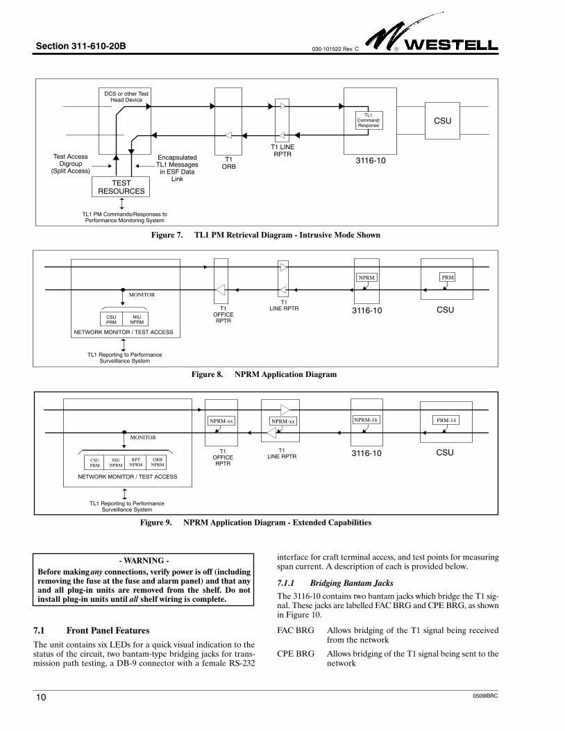
6.9.3 The TL1 commands conform to standard commandssuch as RTRV-PM, INIT-REG, etc. The protocol is a modifiedX.25 LAPB. A generalized diagram of this procedure is shownin Figure 7.
7. HARDWARE OPTIONS & FEATURES
The 3116-10 contains features and options located on the frontand side (PCB) panels, as described in the paragraphs below.
- NOTE -
Set any/all manual option switches prior to installing the unit.
Section 311-610-20B 030-101522 Rev. C
10 0509IBRC
T1ORB
3116-10Test AccessDigroup
(Split Access)
TL1 PM Commands/Responses toPerformance Monitoring System
Figure 7. TL1 PM Retrieval Diagram - Intrusive Mode Shown
DCS or other TestHead Device
EncapsulatedTL1 Messages
in ESF DataLink
TL1Command/Response
TESTRESOURCES
T1 LINERPTR
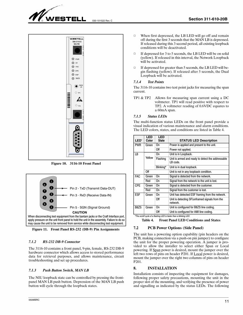
CSU
T1OFFICERPTR
3116-10 CSU
NPRM PRM
CSUPRM
NIUNPRM
MONITOR
NETWORK MONITOR / TEST ACCESS
TL1 Reporting to PerformanceSurveillance System
Figure 8. NPRM Application Diagram
T1LINE RPTR
T1OFFICERPTR
3116-10 CSU
MONITOR
NETWORK MONITOR / TEST ACCESS
TL1 Reporting to PerformanceSurveillance System
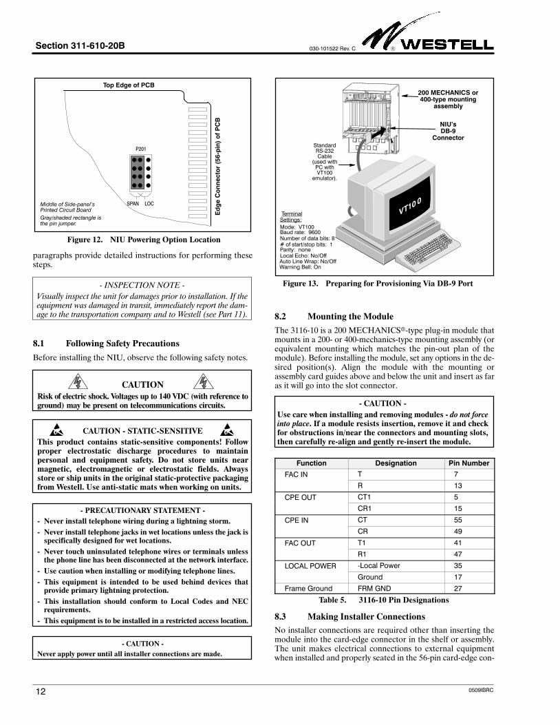
Figure 9. NPRM Application Diagram - Extended Capabilities
T1LINE RPTR
NPRM-16 PRM-14
CSUPRM
NIUNPRM
RPTNPRM
ORBNPRM
NPRM-xxNPRM-xx
- WARNING -
Before making any connections, verify power is off (includingremoving the fuse at the fuse and alarm panel) and that anyand all plug-in units are removed from the shelf. Do notinstall plug-in units until all shelf wiring is complete.
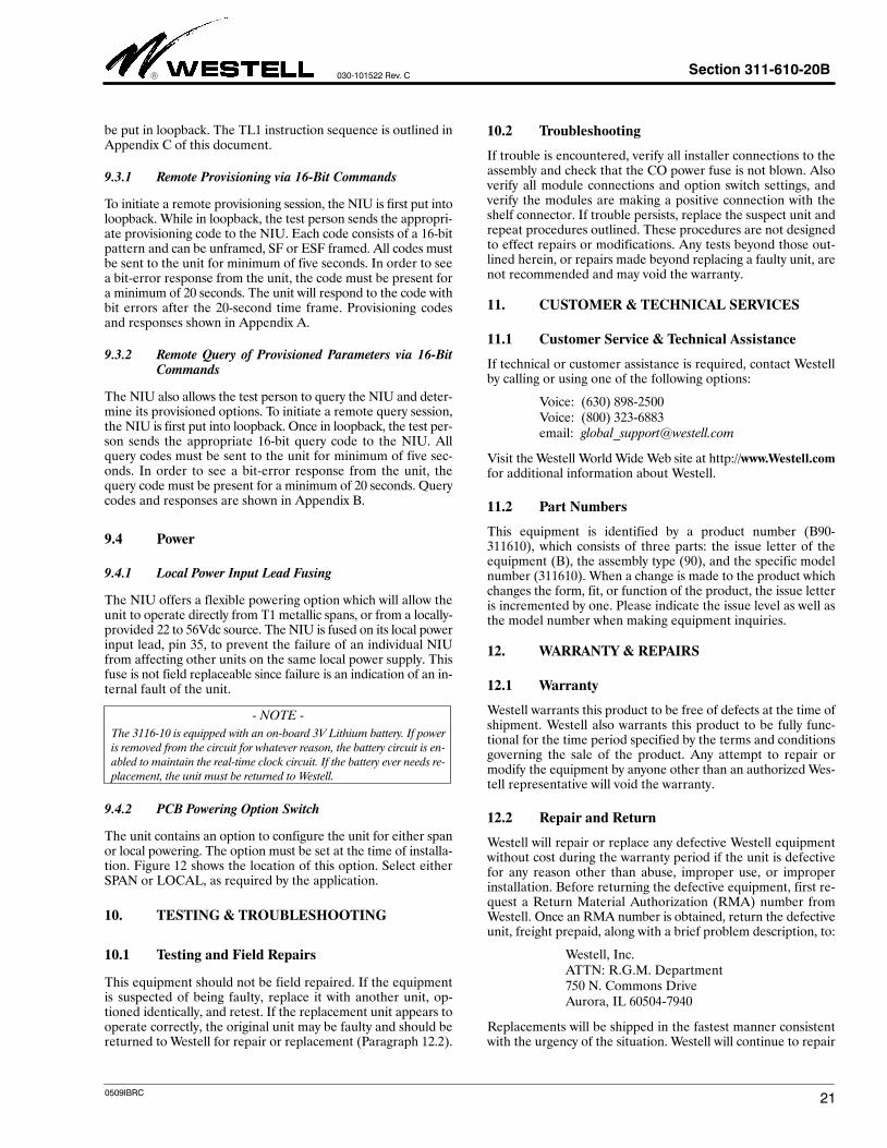
7.1 Front Panel Features
The unit contains six LEDs for a quick visual indication to thestatus of the circuit, two bantam-type bridging jacks for trans-mission path testing, a DB-9 connector with a female RS-232
interface for craft terminal access, and test points for measuringspan current. A description of each is provided below.
7.1.1 Bridging Bantam Jacks
The 3116-10 contains two bantam jacks which bridge the T1 sig-nal. These jacks are labelled FAC BRG and CPE BRG, as shownin Figure 10.
FAC BRG Allows bridging of the T1 signal being receivedfrom the network
CPE BRG Allows bridging of the T1 signal being sent to thenetwork
Section 311-610-20B
030-101522 Rev. C
110509IBRC
Figure 10. 3116-10 Front Panel
B90-311610
125641
NIU-PM
PWR
ESF
FAC
CPE
LB
CPE BRG
TP1
TP2
MANLB
B8ZS
FAC BRG
CAUTIONWhen disconnecting test equipment from the bantam jacks or the Craft Interface port,apply pressure on the unit front panel to hold the unit in the assembly. Failure to do somay cause the unit to be removed from service while disconnecting test equipment.
Pin 3 - RxD (Receive Data-IN)
Pin 2 - TxD (Transmit Data-OUT)
Figure 11. Front Panel RS-232 (DB-9) Pin Assignments
Pin 5 - SGN (Signal Ground)
7.1.2 RS-232 DB-9 Connector
The 3116-10 contains a front panel, 9-pin, female, RS-232 DB-9hardware connector which allows access to stored performancedata for retrieval purposes, and allows maintenance, circuittroubleshooting and set up procedures.
7.1.3 Push Button Switch, MAN LB
The NIU loopback state can be controlled by pressing the front-panel MAN LB push button. Depression of the MAN LB pushbutton will cycle through the loopback states.
When first depressed, the LB LED will go off and remainoff during the first 3 seconds that the MAN LB is depressed.If released during this 3 second period, all existing loopbackconditions will be deactivated.
If depressed for 3 to 5 seconds, the LB LED will be on solid(yellow). If released in this interval, the Network Loopbackwill be activated.
If depressed for greater than 5 seconds, the LB LED will be-gin flashing (yellow). If released after 5 seconds, the DualLoopback will be activated.
7.1.4 Test Points
The 3116-10 contains two test point jacks for measuring the spancurrent.
TP1 & TP2 Allows for measuring span current using a DCvoltmeter. TP1 will read positive with respect toTP2. A voltmeter reading of 0.6VDC equates toa 60mA span.
7.1.5 Status LEDs
The multi-function status LEDs on the front panel provide avisual indication of various maintenance and alarm conditions.The LED colors, states, and conditions are listed in Table 4.
LED‘LEDColor
LEDState STATUS LED Description
PWR Green On Power is applied and present to the unit.
Off Power not applied.
LBY ll
On Unit is in Loopback.Yellow Flashing Unit is armed and ready to detect the addressable
LB code.
Blinking* Unit is in dual loopback.
Off Unit is not in any loopback condition.
FAC Green On Signal is detected from the network.
Red On Signal from the network to the unit is lost.
CPE Green On Signal is detected from the customer.
Red On Signal from the customer is lost.
ESF Green On Unit has detected ESF framing from the network.
Off Unit is detecting SF/unframed signals from thenetwork.
B8ZS Green On Unit is configured for B8ZS line coding.
Off Unit is configured for AMI line coding.
*The on/off cycle of a flashing LED is faster than a blinking LED.
Table 4. Front Panel LED Conditions and States
7.2 PCB Power Options (Side Panel)
The unit has a powering option capability (pin headers on thePCB, making connection via a push-on pin jumper) to configurethe unit for the proper powering operation. A jumper is pro-vided to allow the installer to select either Span or Localpowering. If Span power is desired, mount the jumper over theleft two rows of pins on header P201. If Local power is desired,mount the jumper over the right two columns of pins on headerP201.
8. INSTALLATION
Installation consists of inspecting the equipment for damages,following proper safety precautions, mounting the unit in theproper slot of the mounting, and verifying the presence of powerand signalling as indicated by the status LEDs. The following
Section 311-610-20B 030-101522 Rev. C
12 0509IBRC
SPAN LOC
Top Edge of PCB
Ed
ge
Co
nn
ecto
r (5
6-p
in)
of
PC
B
Figure 12. NIU Powering Option Location
Middle of Side-panel’s Printed Circuit Board
Gray/shaded rectangle is the pin jumper.
P201
paragraphs provide detailed instructions for performing thesesteps.
- INSPECTION NOTE -
Visually inspect the unit for damages prior to installation. If theequipment was damaged in transit, immediately report the dam-age to the transportation company and to Westell (see Part 11).
8.1 Following Safety Precautions
Before installing the NIU, observe the following safety notes.
CAUTION
Risk of electric shock. Voltages up to 140 VDC (with reference toground) may be present on telecommunications circuits.
CAUTION - STATIC-SENSITIVE
This product contains static-sensitive components! Followproper electrostatic discharge procedures to maintainpersonal and equipment safety. Do not store units nearmagnetic, electromagnetic or electrostatic fields. Alwaysstore or ship units in the original static-protective packagingfrom Westell. Use anti-static mats when working on units.
- PRECAUTIONARY STATEMENT -
- Never install telephone wiring during a lightning storm.
- Never install telephone jacks in wet locations unless the jack isspecifically designed for wet locations.
- Never touch uninsulated telephone wires or terminals unlessthe phone line has been disconnected at the network interface.
- Use caution when installing or modifying telephone lines.
- This equipment is intended to be used behind devices thatprovide primary lightning protection.
- This installation should conform to Local Codes and NECrequirements.
- This equipment is to be installed in a restricted access location.
- CAUTION -
Never apply power until all installer connections are made.
NIU’sDB-9
Connector
Baud rate: 9600Number of data bits: 8# of start/stop bits: 1Parity: noneLocal Echo: No/Off
Warning Bell: On
Mode: VT100
Auto Line Wrap: No/Off
StandardRS-232Cable
(used withPC withVT100
emulator).
TerminalSettings:
Figure 13. Preparing for Provisioning Via DB-9 Port
200 MECHANICS or400-type mounting
assembly
8.2 Mounting the Module
The 3116-10 is a 200 MECHANICS-type plug-in module thatmounts in a 200- or 400-mechanics-type mounting assembly (orequivalent mounting which matches the pin-out plan of themodule). Before installing the module, set any options in the de-sired position(s). Align the module with the mounting orassembly card guides above and below the unit and insert as faras it will go into the slot connector.
- CAUTION -
Use care when installing and removing modules - do not forceinto place. If a module resists insertion, remove it and checkfor obstructions in/near the connectors and mounting slots,then carefully re-align and gently re-insert the module.
Function Designation Pin Number
FAC IN T 7
R 13
CPE OUT CT1 5
CR1 15
CPE IN CT 55
CR 49
FAC OUT T1 41
R1 47
LOCAL POWER -Local Power 35
Ground 17
Frame Ground FRM GND 27
Table 5. 3116-10 Pin Designations
8.3 Making Installer Connections
No installer connections are required other than inserting themodule into the card-edge connector in the shelf or assembly.The unit makes electrical connections to external equipmentwhen installed and properly seated in the 56-pin card-edge con-

Section 311-610-20B
030-101522 Rev. C
130509IBRC
Figure 14. A Directory Tree/Path of Software Menus Accessed Via the Craft Interface & VT100 Terminal
Main
Menu
AlarmThresholds
ProvisioningCircuit Status(& Loopbacks)
PerformanceStatistics
Set Clock
Main Menu Screen
on VT100 Terminal
Level 2 -
Level 1 -
Event/AlarmLog
Reports NotePad
Event/AlarmLog Report
ProvisioningReport
Current PMReport
Full PMReport
Delete Record
15 MinuteCurrent Hourly Daily
Add Record
See Figure 15 through Figure 27for sample menu screens.
Help
Change Circuit ID
Change Options
Test ModeProvisioning
Submenus
Figure 15. Main Menu Screen
Westell B90-311610 CLEI: T1L8AC0AAA
MAIN MENU
PROACTT1 PERFORMANCE MONITORING NIU
WESTELL TECHNOLOGIES, INC.AURORA, IL.1-800-323-6883
SELECTIONS
O) PROVISIONINGP) PERFORMANCE STATISTICSS) CIRCUIT STATUSL) EVENT/ALARM LOGC) SET CLOCKT) ALARM THRESHOLDSR) REPORTSN) NOTEPAD?) HELP
Enter letter of selection
nector in the mounting assembly. The pin-outs used by the NIUare listed in Table 5.
9. SET-UP AND OPERATION
9.1 Craft Terminal Setup and Operation
9.1.1 The front-panel craft interface port allows the craft toconfigure the unit for a particular application, view the stored T1performance statistics, as well as graphically view circuit statusand perform various test routines. Each menu provides an asso-ciated HELP screen that explains the function and use of themenu. HELP screens are accessed by pressing (?).
9.1.2 The craft interface port is a DB-9 connector with anelectrical RS-232 female interface in a DCE configuration. The
craft device can be a terminal operating in the VT-100 protocolor a PC running a VT-100 terminal emulator program. If aVT-100 terminal is used a null-modem" cable may be requiredbetween the terminal and the NIU. If a PC with VT-100 emula-tor program is used, a standard RS-232 cable can be used. TheRS-232 port should be set up for 9600 baud, no parity, and onestop bit (NP,1S). The electrical connections to the craft port areshown in Figure 11.
9.2 Menus and Screens
9.2.1 MAIN Menu Screen
Once the terminal or PC is connected to the craft interface port,the MAIN menu should appear. The MAIN menu provides theNIU model number, CLEI code, Technical Service contact tele-phone number, as well as navigation buttons to other screens.

Section 311-610-20B 030-101522 Rev. C
14 0509IBRC
Figure 16. Set Clock Menu Screen (Typical)
Westell B90-311610 CLEI: T1L8AC0AAA
SET CLOCK
Current Time08/28/2003 11:50:23
New Time08/25/2003 09:50:00
Use <tab> to select field, <return> to save, or <Esc> to return to main menu
Figure 17. Provisioning Menu Screen
Westell B90-311610 CLEI: T1L8AC0AAA
PROVISIONING MENU
Option Current New> Monitored Line Coding: B8ZS AMI
Monitored Framing: ESFCPE LOS Response: AISRAI-CI Option: DISABLEDFraming Conversion: DISABLEDReal Time PM mode NONECPE-to-FAC Regen: DISABLEDCPE-to-FAC LBO: DISABLEDFAC-to-CPE Regen: DISABLEDLoopback Timeout: 120 MINUTELoopback Mode NORMALCircuit ID: <UNASSIGNED>
SELECTIONS
S) Save D) Set to default settingsUse <tab> to select option, <space> to change, or Esc to return to main menu
The Model Number and CLEI Code are set at the factory andcannot be changed. The MAIN menu is illustrated in Figure 15.To return to the MAIN menu screen from any other screen enter<Esc>.
9.2.2 SET CLOCK Menu Screen
9.2.2.1 The SET CLOCK screen, Figure 16, is used to set theunit’s internal clock. To reach this screen from the MAIN menu,type <C>. The unit is shipped from the factory with its clock setto Central Standard Time.
9.2.2.2 To set the date or time, use the <tab> to select thefield, then type the new parameter in the highlighted box. Tosave the changes, press <Enter>.
9.2.2.3 To return to the MAIN menu from this screen, pressthe <Esc> key. The clock can be remotely set via TL1 com-mands, using the SET-DAT command.
9.2.3 PROVISIONING Menu Screen
The PROVISIONING screen (Figure 17) is used to configurethe unit’s options. To reach this screen from the MAIN menu,type <O>. The NIU is set from the factory to a standard config-uration. All options in the menu can be set and queriedremotely. For each option, the display shows the CURRENT"configuration as well as a NEW" field that shows what the op-tion can be changed to. Use <tab> or the arrow keys to advanceto an option field. Use the <space> bar to change the availableoptions under the NEW" field.
9.2.3.1 Saving The Changed Options
After configuring the options, press <S> to save the new set-tings. Note: If you enter <Esc> without saving, the system will givea message asking if you want to save the new settings.
- WARNING -
Always save changes before disconnecting to activate the changes. If
the craft terminal is disconnected without saving the changes, the
changes will be lost (unit does not save changes automatically).

Section 311-610-20B
030-101522 Rev. C
150509IBRC
Field/Option Parameter Default* Description
Monitored Line Coding AMI Configures unit for AMI line coding.g
B8ZS Configures unit for B8ZS line coding.
Monitored Framing SF Monitors SF parameters for PM.g
ESF Monitors ESF parameters for PM.
CPE LOS Response None No response to customer LOS.p
LB Enters loopback toward Network upon detecting a Customer LOS.
Idle Send Idle toward Network upon detecting a customer LOS.
AIS Send AIS toward Network upon detecting a Customer LOS.
AIS-CI Send AIS-CI toward Network upon detecting a Customer LOS.
RAI-CI Option Enabled Converts customer RAI to RAI-CI if also receiving a valid network signal.p
Disabled RAI from CPE is always passed unchanged.
Framing Conversion Enabled Enables Fram Conversion.g
Disabled Disabled Frame Conversion.
Real-Time Mode None Disables real-time reporting.
NPRM Configures the unit to send NPRM messages.
SPRM Configures the unit to send SPRM messages.
CPE-to-FAC REGEN Disabled No regeneration in the CPE-to-FAC (Z-A, XMT) path.
Enabled Regeneration in the CPE-to-FAC path.
CPE-to-FAC LBO Disabled Select this option to disable the CPE-to-FAC LBO.
7.5 dB Select this option to select 7.5 dB of LBO.
15 dB Select this option to select 15 dB of LBO.
22.5 dB Select this option select 22.5 dB of LBO.
AB15 dB Select this option if the Auto Binder level of the cable is 15 dB.
AB22.5 dB Select this option if the Auto Binder level of the cable is 22.5 dB.
FAC-to-CPE REGEN Disabled No regeneration in the FAC-to-CPE (A-Z, RCV) path.
Enabled Regeneration in the FAC-to-CPE path.
Loopback Time-out Disabled Loopback will not time-out.p
20 Minute Loopback will automatically time-out 20 minutes after initial activation.
60 Minute Loopback will automatically time-out 60 minutes after initial activation.
120 Minute Loopback will automatically time-out 120 minutes after initial activation.
24 Hour Loopback will automatically time-out 24 hours after initial activation.
Loopback Mode Normal Unit loops up to normal inband/Data Link loopback codes.p
Addressed Unit loops up to unique 16-bit addressed loopback code.
Circuit ID <user defined> This field can be up to 20 alphanumeric characters (user defined).
Table 6. Options and Parameters
9.2.4 PERFORMANCE STATISTICS Menu Screens
The Performance Statistics screens are used to view the storedT1 performance statistics. To reach this screen from the MAINmenu, type <P>. The example screen below (Figure 18), showsvarious performance parameters for both the NET-to-CPE (Ato Z) and CPE-to-NET (Z to A) directions as well as a status reg-ister describing abnormal circuit conditions during the period.By using the selection keys at the bottom of the screen, all His-torical time registers can be examined. Type the appropriatecommand to view the 15-minute, Hourly, and Daily screens orthe <N> for Next and <P> for Previous page commands. Theparameters on these screens are automatically updated at 5-sec-ond intervals. To return to the MAIN menu from this screen,press the <Esc> key.
9.2.4.1 Updates
To stop the automatic updating, type <U>. To resume automat-ic updating, type <U> again.
9.2.4.2 Clearing Status Registers
To clear all stored historical data, type <C>. The system willgive a confirmation message prompting if all data is to becleared. Type <Y> for Yes or <N> for No.
- WARNING -
The clear command <C> affects all performance monitoring
screens. The clear command will clear all data screens regardless of
the activating time interval screen.
9.2.5 Event/Alarm Log Screen
9.2.5.1 The Event/Alarm Log screen is used to view variousevents that occurred on the span during the monitoring period.The log provides time-stamped entries for the most importanttypes of events such as alarm signal detection, loopback, PMRegisters cleared, Event/Alarm Log cleared, Clock setting, lossof signal, power outages, and more. The Event/Alarm Log willretain the 200 most recent events in non-volatile memory. TheEvent/Alarm Log can be viewed locally via the craft interfaceport. An example of a typical Event/Alarm Log screen is shown

Section 311-610-20B 030-101522 Rev. C
16 0509IBRC
Figure 18. 15-Minute PM Status Screen (Typical)
Westell B90-311610 CLEI: T1L8AC0AAA
02/28/2003 09:02:48
15 MINUTE PM STATISTICS
(CURRENT)
FAC-to-CPE CPE to FAC Date: 02/28/2003
CV-L 0 0 Time: 08:00:00ES-L 0 0SES-L 0 0 Stat Register KeyLOSS-L 0 99 −−−−−−−−−−−−−−−−−−
1 LoopbackCV-P 0 0 2 Data IncompleteES-P 0 0 3 Loss of SignalSES-P 0 0 4 UnusedUAS-P 0 99 5 Power Loss
6 AISPDV-SEC 102 2 7 Yellow AlarmB8ZS_SEC 0 0 8 Out of FrameMSEC 102 102STAT .2..5.78 .2..5678
SELECTIONS
Q) 15 Minute H) Hourly D) Daily N) Next P) PreviousU) Disable auto updating C) Clear stored data
Enter selection or <Esc> to go back to main menu
Figure 19. Event/Alarm Log Screen (Typical - Sample Only)
Westell B90-311610 CLEI: T1L8AC0AAA
EVENT/ALARM LOG
No. Date Time Event (1 - 15 of 200)
1 2/28/00 13 : 00 : 00 MANUAL LOOP DOWN2 2/28/00 12 : 50 : 00 MANUAL LOOP UP3 2/28/00 12 : 60 : 15 REMOTE LOOP DOWN4 2/28/00 12 : 05 : 00 REMOTE LOOP UP5 2/28/00 12 : 02 : 30 MANUAL LOOP UP6 2/28/00 12 : 02 : 00 CHANGED CPE REGEN OPTION7 2/28/00 12 : 01 : 20 MANUAL LOOP DOWN8 2/28/00 12 : 00 : 30 CHANGED FAC REGEN OPTION9 2/28/00 11 : 02 : 50 CHANGED FAC REGEN OPTION
10 2/28/00 11 : 02 : 00 MANUAL LOOP UP11 2/28/00 11 : 00 : 00 AIS FROM CPE CLEARED12 2/28/00 10 : 02 : 15 AIS FROM CPE13 2/28/00 10 : 02 : 00 LOS FROM CPE CLEARED14 2/28/00 10 : 00 : 05 LOS FROM CPE15 2/28/00 10 : 00 : 00 POWER UP
SELECTIONS
N) Next page P) Previous page C) Clear log ?) Help
Enter selection or <Esc> to go back to main menu

Section 311-610-20B
030-101522 Rev. C
170509IBRC
Westell B90-311610 CIRCUIT STATUS CLEI: T1L8AC0AAA
LVL: -13.0dBdsx LVL: -13.8dBdsxFRMG: SF FRMG: SFSIG: OK SIG: OK
TO FAC TO CPE
7.5dB LBO
LVL: -12dBdsx LVL: -4.0dBdsxFRMG: SF FRMG: SFSIG: OK Normal Operation SIG: OK
SELECTIONS
^U) Operate Single Loopback T) Provision Test Mode^T) Operate Test Mode
Enter selection or <Esc> to go back to main menu
Figure 20. Typical Circuit Status Screen - Normal Operation
Figure 21. Typical Circuit Status Screen - Facility Loopback
X
X
Westell B90-311610 CIRCUIT STATUS CLEI: T1L8AC0AAA
LVL: -13.0dBdsx LVL: 0.0dBdsxFRMG: SF FRMG: UNF/UNKSIG: OK SIG: AIS
TO FAC AIS TO CPE
REGEN
LVL: -0.0dBdsx LVL: -4.0dBdsxFRMG: SF Facility Loopback FRMG: SIG: OK SIG:
SELECTIONS
^U) operate dual loopback^D) deactivate loopback^T) provision test mode
Enter selection or <Esc> to go back to main menu
in Figure 19. The Event/Alarm Log can also be retrieved re-motely via TL1 commands.
9.2.5.2 To gain access to the Event/Alarm Log screen, type<L> while in the Main Menu. The Event/Alarm Log appears.To advance through the log, type <N> (next page), or <P>(previous page), or <Esc>(to return to the MAIN Menu).
9.2.5.3 To clear all stored data in the Event/Alarm Log, type<C>. The system will give a confirmation message promptingif all data is to be cleared. Type <Y> for Yes or <N> for No.
9.2.6 CIRCUIT STATUS Menu Screen
9.2.6.1 The Circuit Status screen is used to view the NIU cir-cuit status, as well as perform various test routines such asloopback. To reach this screen from the MAIN menu, type <S>.The Circuit Status screen (Figure 20) provides a graphical depic-tion of the NIU and its T1 facility and customer interface ports.
9.2.6.2 For each port, the screen shows:
1. Level (LVL) of the signal in dB. Possible values in this fieldare:0 0dB level detected-1 -1dB level detected
-2 -2dB level detected up to-30 -30dB level detectedLOW Too low to measure (< -30dB)
2. Framing (FRMG) that is present at the port.Possible values in this field are:SF SF framing presentESF ESF framing presentUNF unframedUNK unknown
3. Signal (SIG) status at the port.Possible values here are: OK Normal signal condition

Section 311-610-20B 030-101522 Rev. C
18 0509IBRC
Figure 22. Typical Circuit Status Screen - Dual Loopback
Westell B90-311610 CIRCUIT STATUS CLEI: T1L8AC0AAA
LVL: -13.0dBdsx LVL: 0.0dBdsxFRMG: SF FRMG: SIG: OK SIG:
TO FAC TO CPE
REGEN
LVL: -0.0dBdsx LVL: 0.0dBdsxFRMG: SF Dual Loopback FRMG: SIG: OK SIG:
SELECTIONS
^D) deactivate loopback
Enter selection or <Esc> to go back to main menu
Figure 23. Typical Circuit Status Screen - Facility Loopback with FAC-to-CPE REGEN Enabled
Westell B90-311610 CIRCUIT STATUS CLEI: T1L8AC0AAA
LVL: -0.5dBdsx LVL: 0.0dBdsxFRMG: SF FRMG: UNF/UNKSIG: OK SIG: AIS
REGEN
TO FAC AIS TO CPE
LVL: -0.5dBdsx Facility Loopback LVL: -8.0dBdsxFRMG: SF FRMG: SIG: OK SIG:
SELECTIONS
^U) operate dual loopback^D) deactivate loopback^T) provision test mode
Enter selection or <Esc> to go back to main menu
X
X
LOS Loss Of SignalAIS Alarm Indication Signal (all ones)RAI Remote Alarm Indication (yellow alarm)Idle Customer Disconnect Indication signalRAI-CI Remote Alarm Indication - Customer InterfaceAIS-CI Alarm Indication Signal - Customer Interface
9.2.6.3 The Circuit Status screen also shows a graphical repre-sentation of the internal transmission paths of the NIU, with thespecific regeneration or LBO parameters that have been provi-sioned. When different parameters are provisioned, remotely orvia the provisioning menu, they will be reflected here.
9.2.6.4 By using the <Ctrl> <U> keys simultaneously, theNIU can be placed into Network loopback. See Figure 21. Usingthe <Ctrl> <U> keys simultaneously a second time, the NIUcan be placed into both Network-side and CPE-side (dual) loop-back. See Figure 22. The graphical representation will changeappropriately to show the loopback state as well as the configu-
ration of transmission parameters and options in the loopbackpath. Figure 23 shows the NIU in a single loopback mode whenFAC-to-CPE Regeneration is Enabled.
9.2.6.5 Finally, using the <Ctrl> <D> keys simultaneously,will cause the NIU to deactivate loopback and return the circuitto normal operation. Also, the Loopback Timeout circuit willalso reset to the pre-selected setting.
9.2.7 TEST MODE PROVISIONING Menu Screen
The TEST MODE PROVISIONING screen (Figure 24) is usedto configure the unit’s options for the test mode. To reach thisscreen from the MAIN menu, type <S> to get into the STATUSScreen and then type <T>. For each option, the display showsthe CURRENT" configuration as well as a NEW" field thatshows what the option can be changed to. Use <tab> or the ar-row keys to advance to an option field. Use the <space> bar tochange the available options under the NEW" field.

Section 311-610-20B
030-101522 Rev. C
190509IBRC
Figure 24. Test Mode Provisioning Menu Screen
Westell B90-311610 CLEI: T1L8AC0AAA
TEST MODE PROVISIONING MENU
Option Current New
> Test Pattern: 1:7 1:1
Framing for Pattern SFTest Pattern to CPE ENABLEDTest Pattern to NET: DISABLEDUser Pattern: 10111110
SELECTIONS
S) Save D) Set to default settings
Use <tab> to select option, <space> to change, or Esc to return to main menu
Figure 25. NOTE PAD Screen
Westell B90-311610 CLEI: T1L8AC0AAA
NOTE PAD
No. Date Time Notes
1 06/05/03 14:51:17 NIU PUT INTO SERVICE2 06/05/03 14:51:53 PM DATA CLEARED
SELECTIONS
A) Add record D) Delete record E) Edit record
Enter selection or ESC to go back to previous menu
Field Parameter Default
TEST PATTERN 1:1
1:7
ALL ONES
USER (4-16 BITS)
FRAMING FOR PATTERN UNFRAMED
SF
ESF
TEST PATTERN TO CPE ENABLED
DISABLED
TEST PATTERN TO NET ENABLED
DISABLED
Table 7. 3116-10 Test Mode Parameters
9.2.7.1 Saving The Changed Options
After configuring the options, press <S> to save the new set-tings. Note: If you enter <Esc> without saving, the system will givea message asking if you want to save the new settings.
- WARNING -
If the craft terminal is disconnected without saving the changes, the
changes will be lost (unit does not save changes automatically).
9.2.7.2 The test mode is activated while in the STATUS screenby using the <Ctrl><T> keys simultaneously. Additional ap-plications of <Ctrl><T> will toggle the state of the test mode.
9.2.8 NOTE PAD Screen
The Note Pad screen provides a means for Craft personnel to lognotes about the circuit. See Figure 25. Each entry is date andtime stamped for future reference. Up to 15 notes can be en-tered, with each note limited to 50 characters. Add, delete, andedit selections allow the user to manage entries.
9.2.9 ALARM THRESHOLDS Screen
The ALARM THRESHOLDS screen allows the user to set vari-ous performance monitoring thresholds for the differentparameters, illustrated above in Figure 26. An event will be re-corded in the Event/Alarm log when any parameter threshold isexceeded. A threshold setting of 0" will disable it.
9.2.10 REPORTS screen
The CRAFT port provides a means for downloading various re-ports to a PC running HyperTerminal software. The menuoption for performing this function will be labeled RE-PORTS", and will appear as part of the MAIN menu. Once

Section 311-610-20B 030-101522 Rev. C
20 0509IBRC
Figure 26. ALARM THRESHOLDS Screen
Westell B90-311610 CLEI: T1L8AC0AAA
ALARM THRESHOLDS
PARAMETER 15-MINUTE 1−DAY
> >CV-L 387 0 3865ES-L 25 250SES-L 4 40
CVP-P 382 3820ESP-P 25 250SESP-P 4 40UASP-P 10 10
SELECTIONS
S) SAVE D) SET DEFAULT THRESHOLDS X) DISABLE All THRESHOLDS
NOTE: Setting a threshold to a value of 0 will disable it
Enter selection or ESC to go back to previous menu
Figure 27. REPORTS Screen
Westell B90-311610 CLEI: T1L8AC0AAA
REPORTS MENU
1) Information Report2) Event Log Report3) Current PM Report4) Full PM Report?) Help
Details on saving a report to file are availableon the help screen by pressing the ?" key.
Enter selection or ESC to go back to previous menu
selected, the REPORTS" screen, Figure 27, will allow the userto select from one of four options, labeled as follows:
1. Information Report - Provides all provisioning (includingAlarm Threshold) information about the unit.
2. Event Log Report - Provides all provisioning informationand a complete listing of all stored Event/Alarm Logevents.
3. Current PM Report - Provides all provisioning information,and detailed PM information for the current 15-minute,current hour and current day.
4. Full PM Report - Provides all provisioning information, anda complete listing of all PM information stored in the unit.
Reports Screen Download Procedure
1. Select Transfer," Capture Text" from the Hyper Terminaldrop down menu.
2. Enter a file name then select Start."
3. Select a report number 1," 2," 3," or 4" to capture datafrom the SEND DATA TO LOG FILE" menu.
4. After download is complete, select Transfer," CaptureText," and Stop" from HyperTerminal.
9.3 Remote Provisioning and Query via TL1
The NIU is capable of being provisioned and queried via TL1commands. These TL1 commands and responses are trans-ported via the Facility Data Link and do not require that the unit
Section 311-610-20B
030-101522 Rev. C
210509IBRC
be put in loopback. The TL1 instruction sequence is outlined inAppendix C of this document.
9.3.1 Remote Provisioning via 16-Bit Commands
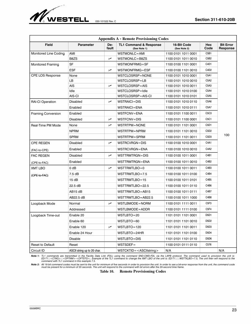
To initiate a remote provisioning session, the NIU is first put intoloopback. While in loopback, the test person sends the appropri-ate provisioning code to the NIU. Each code consists of a 16-bitpattern and can be unframed, SF or ESF framed. All codes mustbe sent to the unit for minimum of five seconds. In order to seea bit-error response from the unit, the code must be present fora minimum of 20 seconds. The unit will respond to the code withbit errors after the 20-second time frame. Provisioning codesand responses shown in Appendix A.
9.3.2 Remote Query of Provisioned Parameters via 16-BitCommands
The NIU also allows the test person to query the NIU and deter-mine its provisioned options. To initiate a remote query session,the NIU is first put into loopback. Once in loopback, the test per-son sends the appropriate 16-bit query code to the NIU. Allquery codes must be sent to the unit for minimum of five sec-onds. In order to see a bit-error response from the unit, thequery code must be present for a minimum of 20 seconds. Querycodes and responses are shown in Appendix B.
9.4 Power
9.4.1 Local Power Input Lead Fusing
The NIU offers a flexible powering option which will allow theunit to operate directly from T1 metallic spans, or from a locally-provided 22 to 56Vdc source. The NIU is fused on its local powerinput lead, pin 35, to prevent the failure of an individual NIUfrom affecting other units on the same local power supply. Thisfuse is not field replaceable since failure is an indication of an in-ternal fault of the unit.
- NOTE -
The 3116-10 is equipped with an on-board 3V Lithium battery. If power
is removed from the circuit for whatever reason, the battery circuit is en-
abled to maintain the real-time clock circuit. If the battery ever needs re-
placement, the unit must be returned to Westell.
9.4.2 PCB Powering Option Switch
The unit contains an option to configure the unit for either spanor local powering. The option must be set at the time of installa-tion. Figure 12 shows the location of this option. Select eitherSPAN or LOCAL, as required by the application.
10. TESTING & TROUBLESHOOTING
10.1 Testing and Field Repairs
This equipment should not be field repaired. If the equipmentis suspected of being faulty, replace it with another unit, op-tioned identically, and retest. If the replacement unit appears tooperate correctly, the original unit may be faulty and should bereturned to Westell for repair or replacement (Paragraph 12.2).
10.2 Troubleshooting
If trouble is encountered, verify all installer connections to theassembly and check that the CO power fuse is not blown. Alsoverify all module connections and option switch settings, andverify the modules are making a positive connection with theshelf connector. If trouble persists, replace the suspect unit andrepeat procedures outlined. These procedures are not designedto effect repairs or modifications. Any tests beyond those out-lined herein, or repairs made beyond replacing a faulty unit, arenot recommended and may void the warranty.
11. CUSTOMER & TECHNICAL SERVICES
11.1 Customer Service & Technical Assistance
If technical or customer assistance is required, contact Westellby calling or using one of the following options:
Voice: (630) 898-2500Voice: (800) 323-6883email: [email protected]
Visit the Westell World Wide Web site at http://www.Westell.comfor additional information about Westell.
11.2 Part Numbers
This equipment is identified by a product number (B90-311610), which consists of three parts: the issue letter of theequipment (B), the assembly type (90), and the specific modelnumber (311610). When a change is made to the product whichchanges the form, fit, or function of the product, the issue letteris incremented by one. Please indicate the issue level as well asthe model number when making equipment inquiries.
12. WARRANTY & REPAIRS
12.1 Warranty
Westell warrants this product to be free of defects at the time ofshipment. Westell also warrants this product to be fully func-tional for the time period specified by the terms and conditionsgoverning the sale of the product. Any attempt to repair ormodify the equipment by anyone other than an authorized Wes-tell representative will void the warranty.
12.2 Repair and Return
Westell will repair or replace any defective Westell equipmentwithout cost during the warranty period if the unit is defectivefor any reason other than abuse, improper use, or improperinstallation. Before returning the defective equipment, first re-quest a Return Material Authorization (RMA) number fromWestell. Once an RMA number is obtained, return the defectiveunit, freight prepaid, along with a brief problem description, to:
Westell, Inc.ATTN: R.G.M. Department750 N. Commons DriveAurora, IL 60504-7940
Replacements will be shipped in the fastest manner consistentwith the urgency of the situation. Westell will continue to repair

Section 311-610-20B 030-101522 Rev. C
22 0509IBRC
or replace faulty equipment beyond the warranty period for anominal charge. Contact Westell for details.
13. SPECIFICATIONS
13.1 Ordering Specifications
To order units, call the telephone number shown in Paragraph11.1 and please specify a specific model number shown inTable 8.
Model # Part # Description
3116-10 B90-311610 DS1 Network Interface Unit (NIU) with PerformanceMonitoring. CLEI* Code: T1L8AC0AAA. Barcode: 125641
*CLEI is a trademark of Telcordia Technologies.
Table 8. Ordering and Option Information
13.2 Electrical and Physical Specifications
The electrical and signalling specifications are listed below, andthe physical specifications are shown in Table 9.
Transmission
A. Insertion Loss (Regen OFF): 1.5 dB, max.
B. Regen Range: -30 to 0 dBDSX
C. Port Impedance: 100 Ohms (±22%) at 772 kHz
Detectors
D. FAC and CPE LOS Detector Thresholds: -30 dB @ 150ms
E. Code Detector Range: -30 to 0 dBDSX
F. Code Detector Maximum Error Rate: 10-3
Power
G. Span Power Voltage Drop: 24V (nom.) at 60 mA
H. Span Power Operating Current: 57 to 63 mA
I. Local Power: -22 to -56 Vdc, ± reference to ground
J. Local Power Current Consumption: 19 mA, typ. at -48Vdc
K. Heat Release (SPAN PWR): 1.44 Watts, typ.
L. Heat Release (LOCAL PWR): 0.91 Watts, typ.
M. Equipped with a 3 V Lithium battery to maintain thereal-time clock. If battery needs replacement, the unitmust be returned to Westell.
13.3 Regulatory/Agency Specifications
Certified to UL standard 60950
Recognized to CAN/CSA C22.2 No. 60950-00
NEBS compliant
Physical Feature U.S. Metric
Height 5.6 inches 14.2 cm
Width 0.7 inches 1.8 cm
Depth 6.0 inches 15.2 cm
Weight (approx.) 6 ounces 170 g
Operating Temp. -40° to 149°F -40° to 65°CHumidity 0 to 95% (non-condensing)
Table 9. Physical Specifications
Section 311-610-20B
030-101522 Rev. C
230509IBRC
Appendix A - Remote Provisioning Codes
Field Parameter De-fault
TL1 Command & Response(See Note 1)
16-Bit Code(See Note 2)
HexCode
Bit ErrorResponse
Monitored Line Coding AMI WSTMONLC=AMI 1100 0101 1011 0001 C5B1g
B8ZS WSTMONLC=B8ZS 1100 0101 1011 0010 C5B2
Monitored Framing SF WSTMONFRMG=SF 1100 0100 1101 0001 C4D1g
ESF WSTMONFRMG=ESF 1100 0100 1101 0010 C4D2
CPE LOS Response None WSTCLOSRSP=NONE 1100 0101 1010 0001 C5A1p
LB WSTCLOSRSP=LB 1100 0101 1010 0010 C5A2
AIS WSTCLOSRSP=AIS 1100 0101 1010 0011 C5A3
Idle WSTCLOSRSP=Idle 1100 0101 1010 0100 C5A4
AIS-CI WSTCLOSRSP=AIS-CI 1100 0101 1010 0101 C5A5
RAI-CI Operation Disabled WSTRAICI=DIS 1100 0101 1010 0110 C5A6p
Enabled WSTRAICI=ENA 1100 0101 1010 0111 C5A7
Framing Conversion Enabled WSTFCNV=ENA 1100 0101 1100 0011 C5C3g
Disabled WSTFCNV=DIS 1100 0101 1100 0001 C5C1
Real-Time PM Mode None WSTRTPM=NONE 1100 0101 1101 0001 C5D1
NPRM WSTRTPM=NPRM 1100 0101 1101 0010 C5D2
SPRM WSTRTPM=SPRM 1100 0101 1101 0011 C5D3100
CPE REGEN Disabled WSTRCVRGN=DIS 1100 0100 1010 0001 C4A1
(FAC-to-CPE) Enabled WSTRCVRGN=ENA 1100 0100 1010 0010 C4A2
FAC REGEN Disabled WSTTRMTRGN=DIS 1100 0100 1011 0001 C4B1
(CPE-to-FAC) Enabled WSTTRMTRGN=ENA 1100 0100 1011 0010 C4B2
XMT LBO 0 dB WSTTRMTLBO=0 1100 0100 1011 0011 C4B3
(CPE-to-FAC) 7.5 dB WSTTRMTLBO=7.5 1100 0100 1011 0100 C4B4(CPE-to-FAC)
15 dB WSTTRMTLBO=15 1100 0100 1011 0101 C4B5
22.5 dB WSTTRMTLBO=22.5 1100 0100 1011 0110 C4B6
AB15 dB WSTTRMTLBO=AB15 1100 0100 1011 0111 C4B7
AB22.5 dB WSTTRMTLBO=AB22.5 1100 0100 1011 1000 C4B8
Loopback Mode Normal WSTLBMODE=NORM 1100 0101 1111 0011 C5F3p
Addressed WSTLBMODE=ADDR 1100 0101 1111 0100 C5F4
Loopback Time-out Enable 20 WSTLBTO=20 1101 0101 1101 0001 D5D1p
Enable 60 WSTLBTO=60 1101 0101 1101 0010 D5D2
Enable 120 WSTLBTO=120 1101 0101 1101 0011 D5D3
Enable 24 Hour WSTLBTO=24HR 1101 0101 1101 0100 D5D4
Disable WSTLBTO=DIS 1101 0101 1101 0110 D5D6
Reset to Default Reset WSTSDEF= 1100 0101 0111 0110 C576
Circuit ID ASCII string up to 20 char. WSTCKTID=<ASCIIstring> N/A N/A
Note 1: TL1 commands are transmitted in the Facility Data Link (FDL) using the command SND-CMD-FDL via the LAPB protocol. The command used to provision the unit is:ED-T1:::<CTAG>:::<OPTNM>-<OPTSTG>;. Example of the TL1 command to change the XMT LBO of the unit is: ED-T1::::::WSTTXLBO=7.5; The unit then will respond to thecommand with TL1 command in this example 7.5.
Note 2: All 16-bit command codes must be sent to the unit for minimum of five seconds in order to provision the unit. In order to see a bit-error response from the unit, the command codemust be present for a minimum of 20 seconds. The unit will respond to the command with bit errors after the 20-second time frame.
Table 10. Remote Provisioning Codes
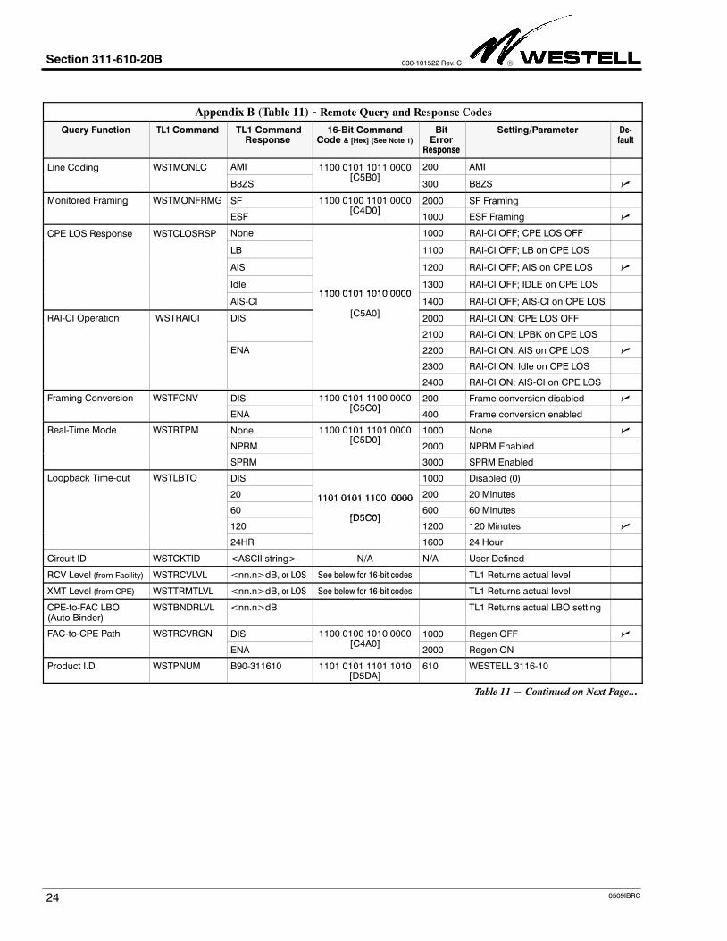
Section 311-610-20B 030-101522 Rev. C
24 0509IBRC
Appendix B (Table 11) - Remote Query and Response Codes
Query Function TL1 Command TL1 CommandResponse
16-Bit CommandCode & [Hex] (See Note 1)
BitError
Response
Setting/Parameter De-fault
Line Coding WSTMONLC AMI 1100 0101 1011 0000[C5B0]
200 AMIg
B8ZS[C5B0]
300 B8ZS
Monitored Framing WSTMONFRMG SF 1100 0100 1101 0000[C4D0]
2000 SF Framingg
ESF[C4D0]
1000 ESF Framing
CPE LOS Response WSTCLOSRSP None 1000 RAI-CI OFF; CPE LOS OFFp
LB 1100 RAI-CI OFF; LB on CPE LOS
AIS 1200 RAI-CI OFF; AIS on CPE LOS
Idle1100 0101 1010 0000
1300 RAI-CI OFF; IDLE on CPE LOS
AIS-CI1100 0101 1010 0000
C
1400 RAI-CI OFF; AIS-CI on CPE LOS
RAI-CI Operation WSTRAICI DIS[C5A0]
2000 RAI-CI ON; CPE LOS OFFp
2100 RAI-CI ON; LPBK on CPE LOS
ENA 2200 RAI-CI ON; AIS on CPE LOS
2300 RAI-CI ON; Idle on CPE LOS
2400 RAI-CI ON; AIS-CI on CPE LOS
Framing Conversion WSTFCNV DIS 1100 0101 1100 0000[C5C0]
200 Frame conversion disabled g
ENA[C5C0]
400 Frame conversion enabled
Real-Time Mode WSTRTPM None 1100 0101 1101 0000[C5D0]
1000 None
NPRM[C5D0]
2000 NPRM Enabled
SPRM 3000 SPRM Enabled
Loopback Time-out WSTLBTO DIS 1000 Disabled (0)p
20 1101 0101 1100 0000 200 20 Minutes
60
1101 0101 1100 0000
[D5C0]600 60 Minutes
120[D5C0]
1200 120 Minutes
24HR 1600 24 Hour
Circuit ID WSTCKTID <ASCII string> N/A N/A User Defined
RCV Level (from Facility) WSTRCVLVL <nn.n>dB, or LOS See below for 16-bit codes TL1 Returns actual level
XMT Level (from CPE) WSTTRMTLVL <nn.n>dB, or LOS See below for 16-bit codes TL1 Returns actual level
CPE-to-FAC LBO (Auto Binder)
WSTBNDRLVL <nn.n>dB TL1 Returns actual LBO setting
FAC-to-CPE Path WSTRCVRGN DIS 1100 0100 1010 0000[C4A0]
1000 Regen OFF
ENA[C4A0]
2000 Regen ON
Product I.D. WSTPNUM B90-311610 1101 0101 1101 1010[D5DA]
610 WESTELL 3116-10
Table 11 − Continued on Next Page...

Section 311-610-20B
030-101522 Rev. C
250509IBRC
Table 11 - Continued. Appendix B - Remote Query and Response Codes
Query Function TL1 Command TL1 CommandResponse
16-Bit CommandCode (See Note 1)
Bit Er-ror Re-sponse
Setting/Parameter De-fault
CPE-to-FAC PathQ
WSTTRMTLBO 0 1000 REGEN OFF; LBO 0dB
Query7.5 1070 REGEN OFF; LBO 7.5dB
15 1150 REGEN OFF; LBO 15dB
22.5 1220 REGEN OFF; LBO 22.5dB
AB15 1100 0100 1011 0000 1500 REGEN OFF; AB15
AB22.5
1100 0100 1011 0000
[C4B0]1700 REGEN OFF; AB22.5
WSTTRMTLBO 0[C4B0]
2000 REGEN ON; LBO 0dB
7.5 2070 REGEN ON; LBO 7.5dB
15 2150 REGEN ON; LBO 15dB
22.5 2220 REGEN ON; LBO 22.5dB
AB15 2500 REGEN ON; AB15
AB22.5 2700 REGEN ON; AB22.5
Loopback ModeQ
WSTLBMODE NORM 1100 0101 1111 0000[C5F0]
1100 Normal Mode pQuery
ADDR[C5F0]
2100 Addressed Mode
Function Code Sequence HexC d
Bit Error Responses and dB LevelsqCode
BER Level BER Level BER Level BER Level
CPE Level Query 1100 0101 0110 1110[C56E]
Unframed, SF or ESF
C56E 6102040
0 dB-1 dB-2 dB4 dB
60708090
-6 dB-7 dB-8dB9dB
120130140160
-12 dB-13 dB-14 dB16 dB
180190200
-18 dB-19 dB-20 dB
Facility Level Query 1100 0101 0110 1111[C56F]
Unframed, SF or ESF
C56F403050
-4 dB-3 dB-5 dB
90100110
-9dB-10 dB-11 dB
160150170
-16 dB-15 dB-17 dB
400410
-21 dBLoss of signal
Note 1: All 16-bit command codes must be sent to the unit for minimum of five seconds in order to provision the unit. In order to see a bit-error response from the unit, the command codemust be present for a minimum of 20 seconds. The unit will respond to the command with bit errors after the 20-second time frame.
Table 11. Remote Query and Response Codes
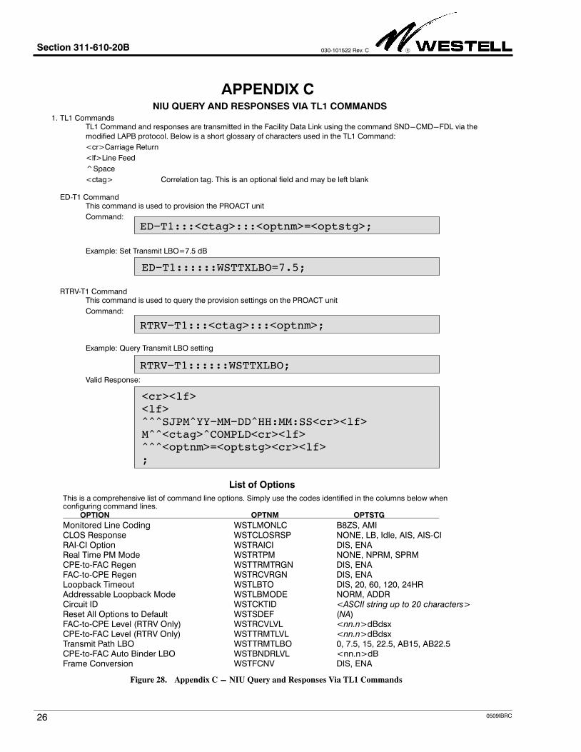
Section 311-610-20B 030-101522 Rev. C
26 0509IBRC
NIU QUERY AND RESPONSES VIA TL1 COMMANDS
APPENDIX C
1. TL1 CommandsTL1 Command and responses are transmitted in the Facility Data Link using the command SND−CMD−FDL via the
modified LAPB protocol. Below is a short glossary of characters used in the TL1 Command:
<cr>Carriage Return
<lf>Line Feed
^Space
<ctag> Correlation tag. This is an optional field and may be left blank
ED-T1 CommandThis command is used to provision the PROACT unit
Command:
ED−T1:::<ctag>:::<optnm>=<optstg>;
Example: Set Transmit LBO=7.5 dB
ED−T1::::::WSTTXLBO=7.5;
RTRV-T1 CommandThis command is used to query the provision settings on the PROACT unit
Command:
RTRV−T1:::<ctag>:::<optnm>;
Valid Response:
<cr><lf><lf>^^^SJPM^YY−MM−DD^HH:MM:SS<cr><lf>M^^<ctag>^COMPLD<cr><lf>^^^<optnm>=<optstg><cr><lf>;
List of Options
This is a comprehensive list of command line options. Simply use the codes identified in the columns below whenconfiguring command lines.
OPTION OPTNM OPTSTG
Monitored Line Coding WSTLMONLC B8ZS, AMICLOS Response WSTCLOSRSP NONE, LB, Idle, AIS, AIS-CIRAI-CI Option WSTRAICI DIS, ENAReal Time PM Mode WSTRTPM NONE, NPRM, SPRMCPE-to-FAC Regen WSTTRMTRGN DIS, ENAFAC-to-CPE Regen WSTRCVRGN DIS, ENALoopback Timeout WSTLBTO DIS, 20, 60, 120, 24HRAddressable Loopback Mode WSTLBMODE NORM, ADDRCircuit ID WSTCKTID <ASCII string up to 20 characters>Reset All Options to Default WSTSDEF (NA)FAC-to-CPE Level (RTRV Only) WSTRCVLVL <nn.n>dBdsxCPE-to-FAC Level (RTRV Only) WSTTRMTLVL <nn.n>dBdsxTransmit Path LBO WSTTRMTLBO 0, 7.5, 15, 22.5, AB15, AB22.5CPE-to-FAC Auto Binder LBO WSTBNDRLVL <nn.n>dBFrame Conversion WSTFCNV DIS, ENA
Example: Query Transmit LBO setting
RTRV−T1::::::WSTTXLBO;
Figure 28. Appendix C − NIU Query and Responses Via TL1 Commands