Embed Size (px)
Citation preview
8/10/2019 Dräger Oxylog 3000 - Service Manuals
http://slidepdf.com/reader/full/draeger-oxylog-3000-service-manuals 1/69
5503.403
9036041
Revision 4.0
Because you care
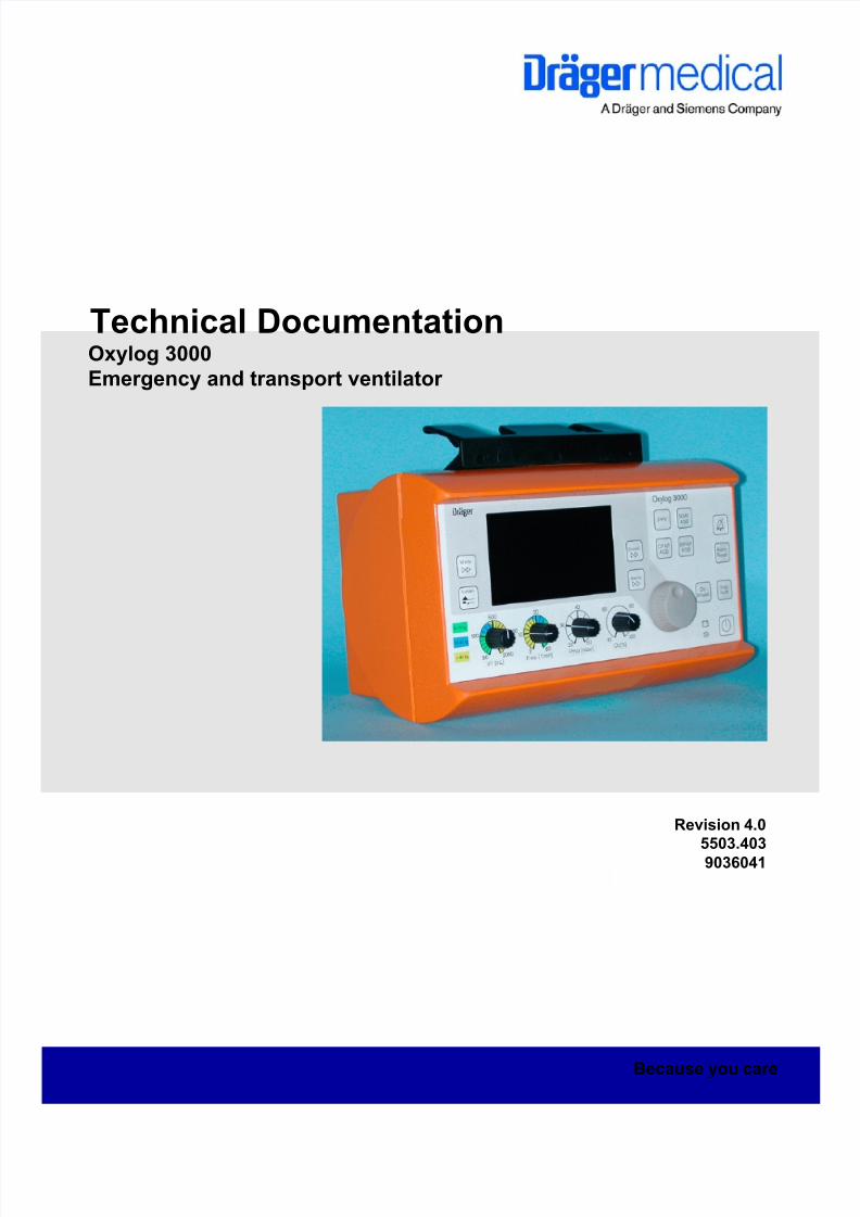
Technical DocumentationOxylog 3000
Emergency and transport ventilator

8/10/2019 Dräger Oxylog 3000 - Service Manuals
http://slidepdf.com/reader/full/draeger-oxylog-3000-service-manuals 2/69
8/10/2019 Dräger Oxylog 3000 - Service Manuals
http://slidepdf.com/reader/full/draeger-oxylog-3000-service-manuals 3/69
A l l r i g h t s r e s e r v
e d . C o p y r i g h t r e s e r v e d .
K 5 5 0 3 4 0 3 I E C I V Z . f m
0 3 . 0 4 . 0 6
I
Contents
General
1 Symbols and Definitions 1
2 Notes 1
Function Description
1 General introduction 5
1.1 Monitoring ............................................................................................................................... 5
1.2 Area of application .................................................................................................................. 5
2 Principle of operation 5
3 Pneumatic system 6
3.1 Inlet ......................................................................................................................................... 6
3.2 Metering ................................................................................................................................. 6
3.3 Sensors and safety functions ................................................................................................. 7
3.4 PEEP valve ............................................................................................................................ 8
3.5 Ambient pressure conditions .................................................................................................. 9
4 Electronics 9
4.1 Charging circuit PCB .............................................................................................................. 9
4.2 Sensor PCB .......................................................................................................................... 10
4.3 Front membrane ................................................................................................................... 10
4.4 Control PCB ......................................................................................................................... 10
8/10/2019 Dräger Oxylog 3000 - Service Manuals
http://slidepdf.com/reader/full/draeger-oxylog-3000-service-manuals 4/69
A l l r i gh t s r e s er v e d . C o p
y r i gh t r e s er v e d .
K 5 5 0 3 4 0 3
I E C I V Z .f m 0 3 . 0 4 . 0 6
II
Contents
Maintenance Procedures
1 Replacing the filter element 13
2 Replacing the internal battery 14
Schematics and Diagrams
1 General introduction 17
Annex
Parts catalog
Test List
Technical Information

8/10/2019 Dräger Oxylog 3000 - Service Manuals
http://slidepdf.com/reader/full/draeger-oxylog-3000-service-manuals 5/69
1
General

8/10/2019 Dräger Oxylog 3000 - Service Manuals
http://slidepdf.com/reader/full/draeger-oxylog-3000-service-manuals 6/692
8/10/2019 Dräger Oxylog 3000 - Service Manuals
http://slidepdf.com/reader/full/draeger-oxylog-3000-service-manuals 7/69
Folderno.
A l l r i g h t s r e s e r v
e d . C o p y r i g h t r e s e r v e d .
V e r s i o n 3 . 0_
R e l e a s e d_
P r i n t e d o n_
0 3 . 0 4 . 0 6_
G e n e r a l_ T e c h n i c a l_ D o c u m e n t a
t i o n . f m
1
Devicename General
1 Symbols and Defini-tions
2 Notes This Technical Documentation conforms to the IEC 60601-1 standard.
Read each step in every procedure thoroughly before beginning any test.
Always use the proper tools and specified test equipment. If you deviate from
the instructions and/or recommendations in this Technical Documentation,
the equipment may operate improperly or unsafely, or the equipment could
be damaged.
It is our recommendation to use only Dräger parts and supplies.
The maintenance procedures described in this Technical Documentation may
be performed by qualified service personnel only. These maintenance proce-
dures do not replace inspections and servicing by the manufacturer.
The information in this Technical Documentation is confidential and may not
be disclosed to third parties without the prior written consent of the manufac-
turer.
This Technical Documentation is for the purpose of information only. Product
descriptions found in this Technical Documentation are in no way a substitute
for reading and studying the Instructions for Use/Operating Manual enclosed
with the product at the time of delivery.
WARNING
A WARNING statement provides important information about a poten-
tially hazardous situation which, if not avoided, could result in deathor serious injury.
CAUTION
A CAUTION statement provides important information about a potentially
hazardous situation which, if not avoided, may result in minor or moderate
injury to the user or patient or in damage to the equipment or other prop-
erty.
NOTE
A NOTE provides additional information intended to avoid inconvenience
during operation.
Definitions according to German standard DIN 31051:
Inspection = examination of actual condition
Maintenance = measures to maintain specified condition
Repair = measures to restore specified condition
Servicing = inspection, maintenance, and repair
8/10/2019 Dräger Oxylog 3000 - Service Manuals
http://slidepdf.com/reader/full/draeger-oxylog-3000-service-manuals 8/69
A l l r i g h t s r e s e r v e d . C o p y r i g h t r e s e r v e d .
V e r s i o n 3 . 0_
R e l e a s e d_
P r i n t e d o n_
0 3 . 0 4 . 0 6_
G e n e r a l_ T e c h n i c a l_ D o c u m e n t a t i o n . f m
2 Folderno.
General Devicename
Know-how contained in this Technical Documentation is subject to ongoing
change through research and development and Dräger Medical reserves the
right to make changes to this Technical Documentation without notice.
NOTE
Unless otherwise stated, reference is made to laws, regulations or stan-
dards (as amended) applicable in the Federal Republic of Germany for
equipment used or serviced in Germany. Users or technicians in all other
countries must verify compliance with local laws or applicable international
standards.

8/10/2019 Dräger Oxylog 3000 - Service Manuals
http://slidepdf.com/reader/full/draeger-oxylog-3000-service-manuals 9/69
3
Function Description

8/10/2019 Dräger Oxylog 3000 - Service Manuals
http://slidepdf.com/reader/full/draeger-oxylog-3000-service-manuals 10/694
8/10/2019 Dräger Oxylog 3000 - Service Manuals
http://slidepdf.com/reader/full/draeger-oxylog-3000-service-manuals 11/69
5503.403
A l l r i g h t s r e s e r v
e d . C o p y r i g h t r e s e r v e d .
V e r s i o n 1 . 1_
R e l e a s e d_
P r i n t e d o n_
0 3 . 0 4 . 0 6_
F 5 5 0 3 4 0 3 T 0 1_
F u n k t i o n . f m
5
Oxylog 3000 Function Description
1 General introduction Oxylog 3000 is an emergency and transport ventilator for short-time treat-
ment of lung damage of a wide variety of kinds. It provides timed and volume-
controlled ventilation, as well as assisting the patient’s breathing in pressure-
controlled mode.
1.1 Monitoring – Airway pressure Paw
– Expiratory minute volume MV
– Apnoea
1.2 Area of application – Mobile use in emergency medicine or primary care of emergency
patients.
– In transit in emergency vehicles or helicopters.
– During transfers by road and air.
– In the emergency room.
– During secondary transfers from hospital to hospital.
2 Principle of opera-tion
Oxylog 3000 primarily comprises the pneumatic components with the con-
nection and metering block and the control and display electronics (Figure 1).
The connection block supplies a constant pressure to the metering block,
contains the safety functions such as the emergency air and safety valves,
control the pressure (PEEP) during expiration and, together with the ventila-
tion accessories, provides the interface to the patient.
The metering block passes defined volumes of gas between 40% and 100%
oxygen to the connection block.
The control and display electronics evaluate the measurement signals, con-
trol the valves and provide the interface to the operator.
8/10/2019 Dräger Oxylog 3000 - Service Manuals
http://slidepdf.com/reader/full/draeger-oxylog-3000-service-manuals 12/69
A l l r i g h t s r e s e r v e d . C o p y r i g h t r e s e r v e d .
V e r s i o n 1 . 1_
R e l e a s e d_
P r i n t e d o n_
0 3 . 0 4 . 0 6_
F 5 5 0 3 4 0 3 T 0 1_
F u n k t i o n . f m
6 5503.403
Function Description Oxylog 3000
Figure 1 Principle of operation
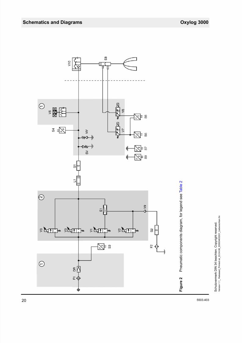
3 Pneumatic system The following description relates to the pneumatic components diagram Oxy-
log 3000. The evaluation of the measurement signals from the sensors and
operation of the valves is handled on the control PCB.
3.1 Inlet The compressed oxygen passed through the filter F1 and the pressure regu-
lator DR to the valves V1 to V3. The pressure regulator regulates the pres-
sure to 3 bar. This is done to attain a stable flow control. The control PCB
monitors this pressure, which is measured with sensor S3.
3.2 Metering Valves V1 to V3 are proportional valves, each delivering a flow proportional to
the overall flow of 0 to 35 L/min. The flow sensor S1 measures the delivered
flow and the control PCB corrects the valve operation as necessary.
Valve V3 comprises two parallel configured valves, to produce a total flow
greater than 100 L/min.
8/10/2019 Dräger Oxylog 3000 - Service Manuals
http://slidepdf.com/reader/full/draeger-oxylog-3000-service-manuals 13/69
5503.403
A l l r i g h t s r e s e r v
e d . C o p y r i g h t r e s e r v e d .
V e r s i o n 1 . 1_
R e l e a s e d_
P r i n t e d o n_
0 3 . 0 4 . 0 6_
F 5 5 0 3 4 0 3 T 0 1_
F u n k t i o n . f m
7
Oxylog 3000 Function Description
With the valve V1 and the ejector E1 ambient air can additionally be drawn in.
Valve V1 meters a flow through the ejector. The resultant negative pressure
draws ambient air through the filter F2, the flow sensor S2 and the non-return
valve V9.
Valve V2 adds oxygen to the ambient air depending on the pre-set O2 con-
centration. The flow sensor S2 measures the intake air flow and the control
PCB corrects valves V1 and V2 accordingly.
The proportion of ambient air may be a maximum of 75%. The minimum oxy-
gen concentration may thus be 40%.
At flows less than 9 L/min the volume of intake air is so low that an oxygen
concentration of 40% is no longer guaranteed. At flows greater than 35 L/min
oxygen is added accordingly. An oxygen concentration of 40% is no longer
guaranteed.
In a flow range from 9 to 35 L/min an oxygen concentration of 40% to 100%
can be set. The non-return valve V9 prevents oxygen escaping into the ambi-
ent air. L1 prevents swirling, and ensures a uniform oxygen concentration.
3.3 Sensors and safetyfunctions
The flow sensor S1 measures the inspiratory flow inside the unit and the con-
trol PCB corrects the operation of valves V1 to V3 as necessary based on the
measured value.
The safety valve SV opens at a pressure greater than 80 mbar, to prevent the
patient from being exposed to high pressure in the event of unit malfunctions.
The emergency breathing valve NV allows the patient to breathe spontane-ously in case the unit fails.
The pressure sensor S4 measures the internal patient pressure inside the
unit and the PEEP pressure at the ventilation valve V10.
The pressure sensor S6 measures the differential pressure above the flow
sensor S8 located close to the patient (Figure 2). From it, the control PCB cal-
culates the flow.
8/10/2019 Dräger Oxylog 3000 - Service Manuals
http://slidepdf.com/reader/full/draeger-oxylog-3000-service-manuals 14/69
A l l r i g h t s r e s e r v e d . C o p y r i g h t r e s e r v e d .
V e r s i o n 1 . 1_
R e l e a s e d_
P r i n t e d o n_
0 3 . 0 4 . 0 6_
F 5 5 0 3 4 0 3 T 0 1_
F u n k t i o n . f m
8 5503.403
Function Description Oxylog 3000
Figure 2 Block diagram of external flow sensor
The pressure sensor S5 measures the pressure at the patient. Based on this
pressure value, the control PCB makes calculations including for actuation of
the PEEP valve V6.
Valves V7 and V8 switch the connections of S6, S5 against atmosphere at
cyclic intervals. The control PCB calibrates the sensors and any offset drift isprevented.
3.4 PEEP valve The PEEP valve V6 controls the PEEP setting of the ventilation valve V10.
The control PCB actuates a coil which delivers a pressure to a diaphragm.
The internal tubing system vents to this pre-set PEEP pressure during expira-
tion.
This PEEP pressure also acts on a valve diaphragm in the ventilation valve
V10 (Figure 3/1). On expiration the pre-set PEEP pressure is established at
the patient.
During expiration an internal flow of 0.5 L/min flows through the PEEP valve
V6 to hold the diaphragm of the PEEP valve still and ensure uniform opening
of the PEEP valve.
During inspiration the PEEP valve V6 closes at 100 mbar.
8/10/2019 Dräger Oxylog 3000 - Service Manuals
http://slidepdf.com/reader/full/draeger-oxylog-3000-service-manuals 15/69
5503.403
A l l r i g h t s r e s e r v
e d . C o p y r i g h t r e s e r v e d .
V e r s i o n 1 . 1_
R e l e a s e d_
P r i n t e d o n_
0 3 . 0 4 . 0 6_
F 5 5 0 3 4 0 3 T 0 1_
F u n k t i o n . f m
9
Oxylog 3000 Function Description
Figure 3 Ventilation valve
3.5 Ambient pressureconditions
Oxylog 3000 meters the tidal volume under BTPS conditions. Sensors S7
and S9 measure the ambient pressure. S5 measures the current pressure
level in the lung. In this way the control PCB can balance fluctuating ambient
pressure and the BTPS conditions (Body Temperature, Pressure, Saturated.
Measurements referred to conditions of the patient’s lung, body temperature
37 °C, ambient pressure, water vapour saturated gas).
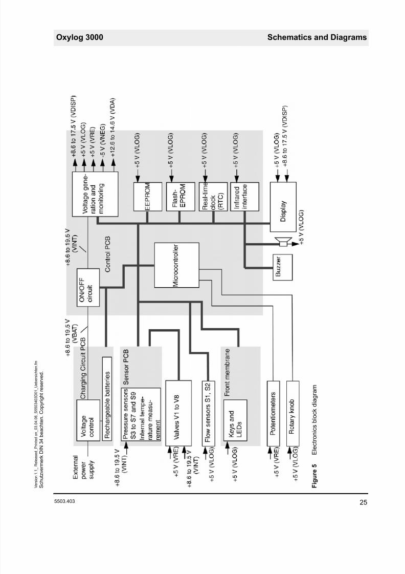
4 Electronics The following description relates to the electronics and represents only theprinciple of operation. The connections of the individual modules are only
indicated indirectly, and are made by cable harnesses, connectors and the
conductors on the individual PCBs.
4.1 Charging circuitPCB
The charging circuit PCB controls charging of the internal replaceable battery
and selection of the voltage supply (mains, on-board system or internal bat-
tery).
The charging circuit PCB accommodates the input for the external voltage
supply. The input is isolated from the remaining electronics by a protective
circuit.
The charging circuit PCB directly activates the power indicator LEDs. The
LEDs are located on the front membrane cover.
The charging circuit PCB has its own processor system, and thus its own
software. This software is also located on the control PCB, and is loaded from
there onto the charging circuit PCB.
The internal replaceable battery has various dummy resistors, depending on
the type used. The charging circuit PCB detects on the basis of the resistor
which type is fitted (nickel metal hydride or lithium ion).
The temperature and charge capacity of the internal replaceable battery isdetermined by the battery itself. These data are transmitted from the charging
circuit PCB to the control PCB.
8/10/2019 Dräger Oxylog 3000 - Service Manuals
http://slidepdf.com/reader/full/draeger-oxylog-3000-service-manuals 16/69
A l l r i g h t s r e s e r v e d . C o p y r i g h t r e s e r v e d .
V e r s i o n 1 . 1_
R e l e a s e d_
P r i n t e d o n_
0 3 . 0 4 . 0 6_
F 5 5 0 3 4 0 3 T 0 1_
F u n k t i o n . f m
10 5503.403
Function Description Oxylog 3000
4.2 Sensor PCB The sensor PCB holds all the pressure sensors of the pneumatic system and
the internal temperature gauge. The sensor PCB is the interface for pressure
measurement and valve actuation between the pneumatic and electronic sys-
tems.
4.3 Front membrane On the front membrane cover are the keys, the LEDs and the turn knob.
Together with the monitor, the turn knob and the potentiometers, the front
membrane is the interface between the unit and the operator. The monitor is
an EL (Electro Luminescent) display.
4.4 Control PCB The control PCB holds the electronic On/Off circuit, the generator for the indi-
vidual internal operating voltages and the microprocessor system to control
and monitor ventilation.
The electronic On/Off circuit is operated directly by the unit’s On/Off button.
In case of a power failure while the unit is on, an alarm generator delivers an
acoustic signal. A Goldcap capacitor delivers the voltage for the signal.
The voltage generator generates the various operating voltages from the sup-
ply voltage, such as the +5 Volts for the microprocessor.
The microprocessor system comprises the microcontroller, an EEPROM, a
Flash-EPROM, a RAM and a real-time clock (RTC).
The EEPROM holds the calibration data, software options, ID number, unit
and service operating hours and the start-up conditions. The Flash-EPROM
holds the medical device software and the software for the charging circuit
PCB. The real-time clock generates the time and date. The real-time clock’sRAM also holds the logs.
The microprocessor system evaluates the measurement signals from the
sensors, the settings of the potentiometers and the turn knob and operates
the valves and the display accordingly.
On a change of software the unit no longer needs to be opened. The infrared
interface transfers the data from the PC/laptop to the microcontroller and vice
versa.

8/10/2019 Dräger Oxylog 3000 - Service Manuals
http://slidepdf.com/reader/full/draeger-oxylog-3000-service-manuals 17/69
11
Maintenance Procedures

8/10/2019 Dräger Oxylog 3000 - Service Manuals
http://slidepdf.com/reader/full/draeger-oxylog-3000-service-manuals 18/6912
8/10/2019 Dräger Oxylog 3000 - Service Manuals
http://slidepdf.com/reader/full/draeger-oxylog-3000-service-manuals 19/69
5503.403
A l l r i g h t s r e s e r v
e d . C o p y r i g h t r e s e r v e d .
V e r s i o n 1 . 1_
R e l e a s e d_
P r i n t e d o n_
0 3 . 0 4 . 0 6_
W 5 5 0 3 4 0 3 T 0 3_
F i l t e r e i n s a t z . f m
13
Oxylog 3000 Maintenance Procedures
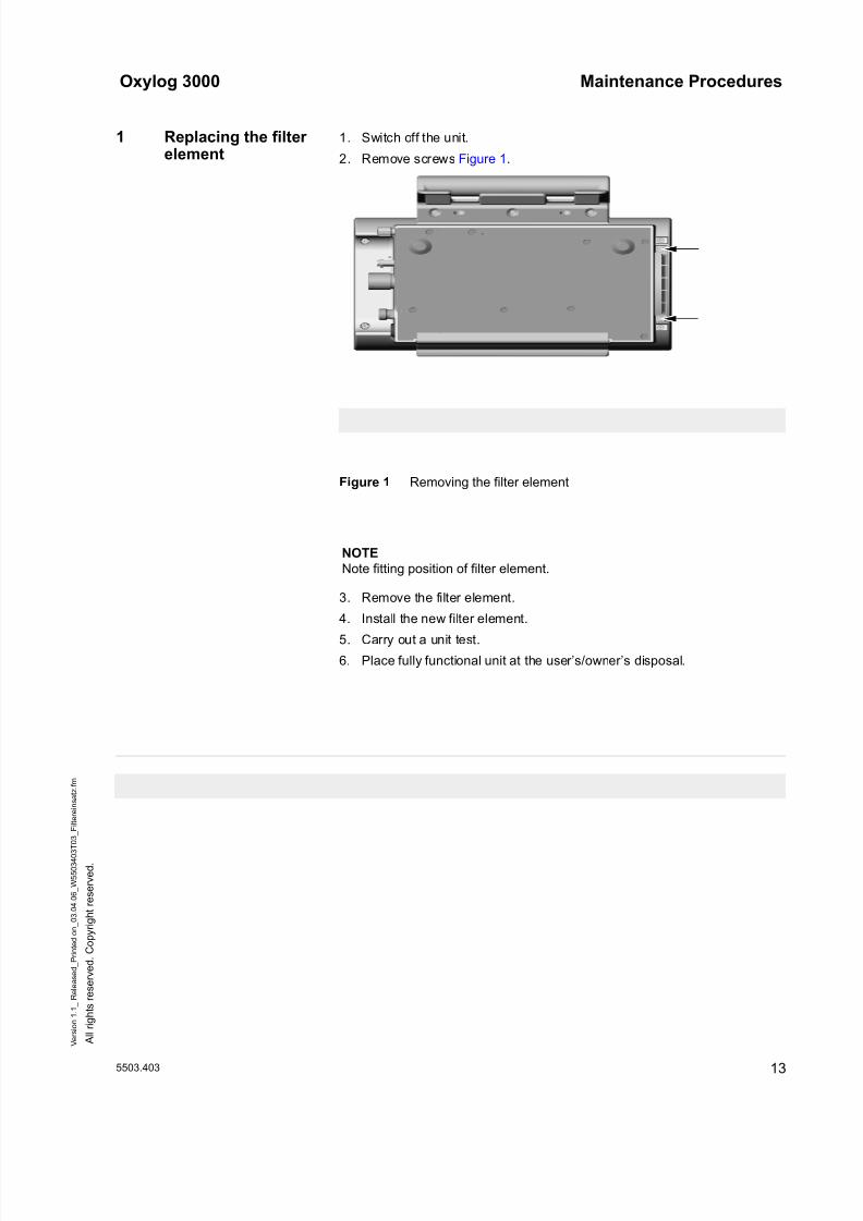
1 Replacing the filterelement
1. Switch off the unit.
2. Remove screws Figure 1.
Figure 1 Removing the filter element
3. Remove the filter element.
4. Install the new filter element.
5. Carry out a unit test.
6. Place fully functional unit at the user’s/owner’s disposal.
NOTE
Note fitting position of filter element.
8/10/2019 Dräger Oxylog 3000 - Service Manuals
http://slidepdf.com/reader/full/draeger-oxylog-3000-service-manuals 20/69
A l l r i g h t s r e s e r v e d . C o p y r i g h t r e s e r v e d .
V e r s i o n 1 . 1_
R e l e a s e d_
P r i n t e d o n_
0 3 . 0 4 . 0 6_
W 5 5 0 3 4 0 3 T 0 6_
W e c h s e l a k k u . f m
14 5503.403
Maintenance Procedures Oxylog 3000
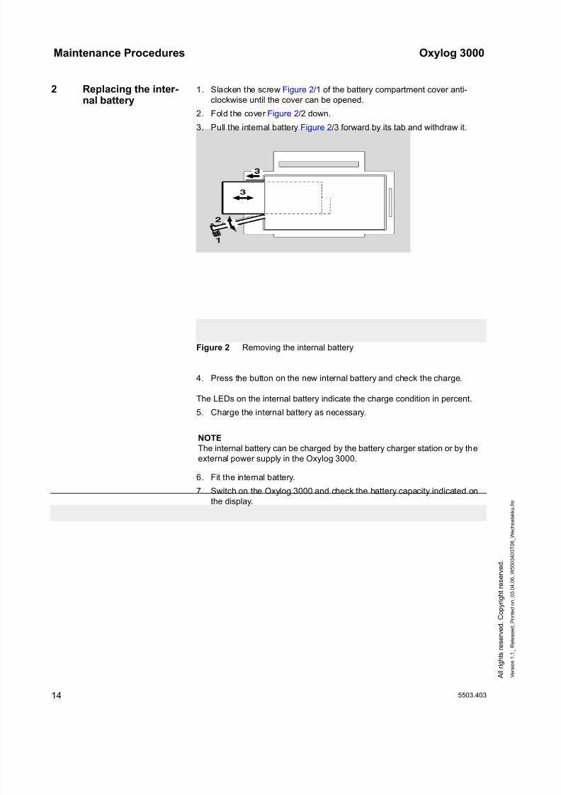
2 Replacing the inter-nal battery
1. Slacken the screw Figure 2/1 of the battery compartment cover anti-
clockwise until the cover can be opened.
2. Fold the cover Figure 2/2 down.
3. Pull the internal battery Figure 2/3 forward by its tab and withdraw it.
Figure 2 Removing the internal battery
4. Press the button on the new internal battery and check the charge.
The LEDs on the internal battery indicate the charge condition in percent.
5. Charge the internal battery as necessary.
6. Fit the internal battery.
7. Switch on the Oxylog 3000 and check the battery capacity indicated on
the display.
NOTE
The internal battery can be charged by the battery charger station or by the
external power supply in the Oxylog 3000.

8/10/2019 Dräger Oxylog 3000 - Service Manuals
http://slidepdf.com/reader/full/draeger-oxylog-3000-service-manuals 21/69
15
Schematics and Diagrams

8/10/2019 Dräger Oxylog 3000 - Service Manuals
http://slidepdf.com/reader/full/draeger-oxylog-3000-service-manuals 22/69
8/10/2019 Dräger Oxylog 3000 - Service Manuals
http://slidepdf.com/reader/full/draeger-oxylog-3000-service-manuals 23/69
8/10/2019 Dräger Oxylog 3000 - Service Manuals
http://slidepdf.com/reader/full/draeger-oxylog-3000-service-manuals 24/69
Schematics and Diagrams Oxylog 3000
18 5503.403
S c h u t z v e r m e r k D I N 3 4 b e a c h t e n . C o p y r i g h t r e s e r v e d .
V e r s i o n 1 . 1_
R e l e a s e d_
P r i n t e d o n_
0 3 . 0 4 . 0 6_
S 5 5 0 3 4 0 3 D 0 1_
U e b e r s i c h t e n
. f m
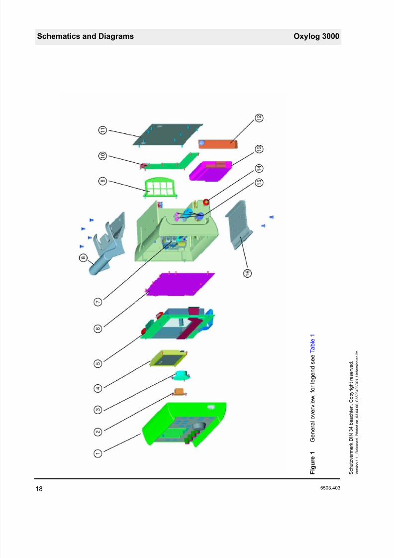
F i g u r e 1
G e n e r a l o v e r v i e w , f o r l e g e n d s e e
T a b l e 1
8/10/2019 Dräger Oxylog 3000 - Service Manuals
http://slidepdf.com/reader/full/draeger-oxylog-3000-service-manuals 25/69
Oxylog 3000 Schematics and Diagrams
5503.403 19
S c h u t z v e r m e r k D I N 3 4 b e a c h t e n . C o p y r i g h t r e s e r v e d .
V e r s i o n 1 . 1_
R e l e a
s e d_
P r i n t e d o n_
0 3 . 0 4 . 0 6_
S 5 5 0 3 4 0 3 D 0 1_
U e b e r s i c h t e n
. f m
T a b l e 1
L e g e n d F i g u r e 1
I t e m
D e s i g n a t i o n
1
F r o n t s e c t i o n w i t h p o t e n t i o m
e t e r , r o t a r y e n c o d e r , m e m b r a n e k e y p a d a n d l a b e l i n s e r t s
2
S i g n a l g e n e r a t o r
3
L o u d s p e a k e r
4
D i s p l a y
5
C o n t r o l P C B ( s e e a l s o F i g u r e 6 )
6
C o v e r p a n e l f o r p n e u m a t i c c
o m p o n e n t s
7
P n e u m a t i c c o m p o n e n t s a n d
s e n s o r P C B ( s e e a l s o F i g u r e 3 )
8
H a n d l e
9
F i l t e r e l e m e n t t o f i l t e r t h e a m
b i e n t a i r i n t a k e
1 0
C h a r g i n g c i r c u i t P C B
1 1
R e a r p a n e l
1 2
B a t t e r y c o m p a r t m e n t c o v e r
1 3
R e p l a c e a b l e b a t t e r y
1 4
D C v o l t a g e s o c k e t
1 5
S o c k e t s f o r f l o w m e t e r t u b e s , v e n t i l a t i o n t u b e a n d c o m p r e s s e d
g a s t u b e
1 6
B a s e p l a t e
8/10/2019 Dräger Oxylog 3000 - Service Manuals
http://slidepdf.com/reader/full/draeger-oxylog-3000-service-manuals 26/69
Schematics and Diagrams Oxylog 3000
20 5503.403
S c h u t z v e r m e r k D I N 3 4 b e a c h t e n . C o p y r i g h t r e s e r v e d .
V e r s i o n 1 . 1_
R e l e a s e d_
P r i n t e d o n_
0 3 . 0 4 . 0 6_
S 5 5 0 3 4 0 3 D 0 1_
U e b e r s i c h t e n
. f m
F i g u r e 2
P n e u m a t i c c o m p o n e n t s d i a g r a m , f o r l e g e n d s e e T a b l e 2
8/10/2019 Dräger Oxylog 3000 - Service Manuals
http://slidepdf.com/reader/full/draeger-oxylog-3000-service-manuals 27/69
Oxylog 3000 Schematics and Diagrams
5503.403 21
S c h u t z v e r m e r k D I N 3 4 b e a c h t e n . C o p y r i g h t r e s e r v e d .
V e r s i o n 1 . 1_
R e l e a
s e d_
P r i n t e d o n_
0 3 . 0 4 . 0 6_
S 5 5 0 3 4 0 3 D 0 1_
U e b e r s i c h t e n
. f m
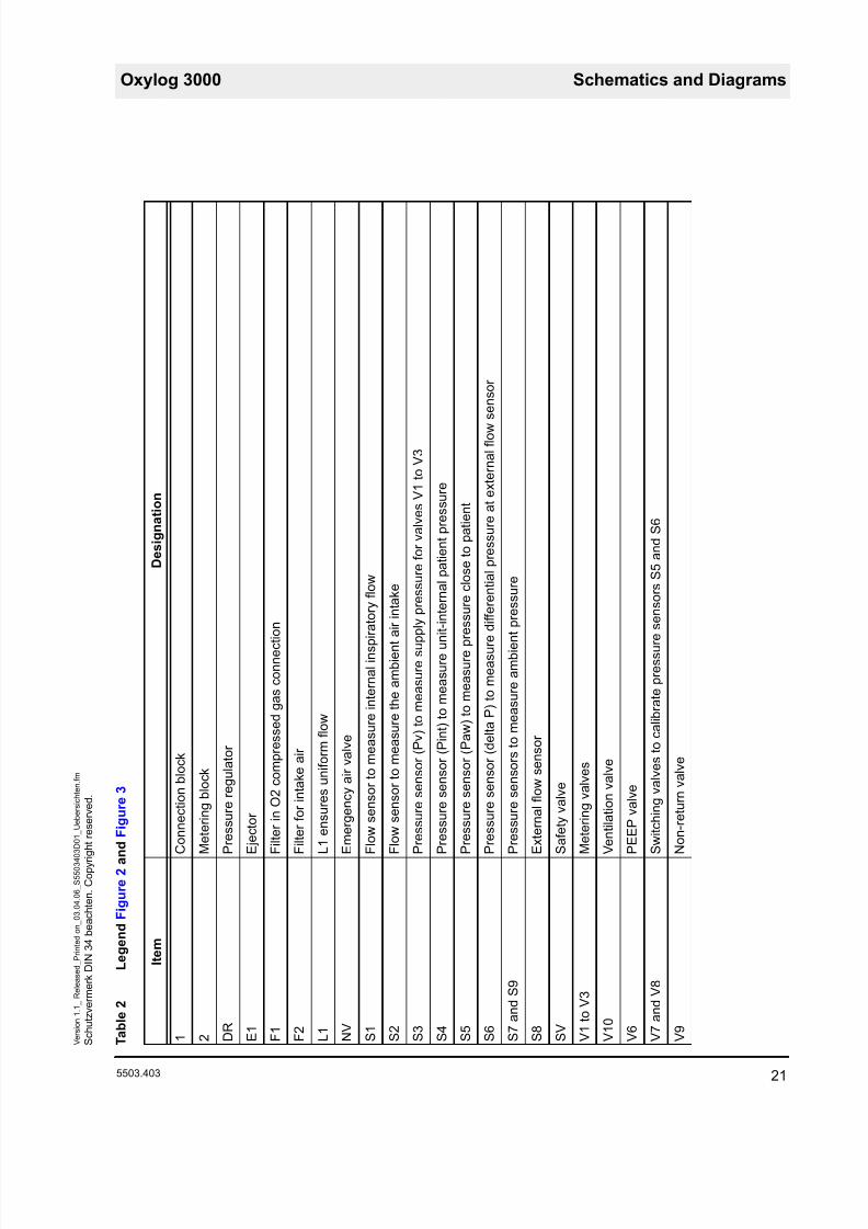
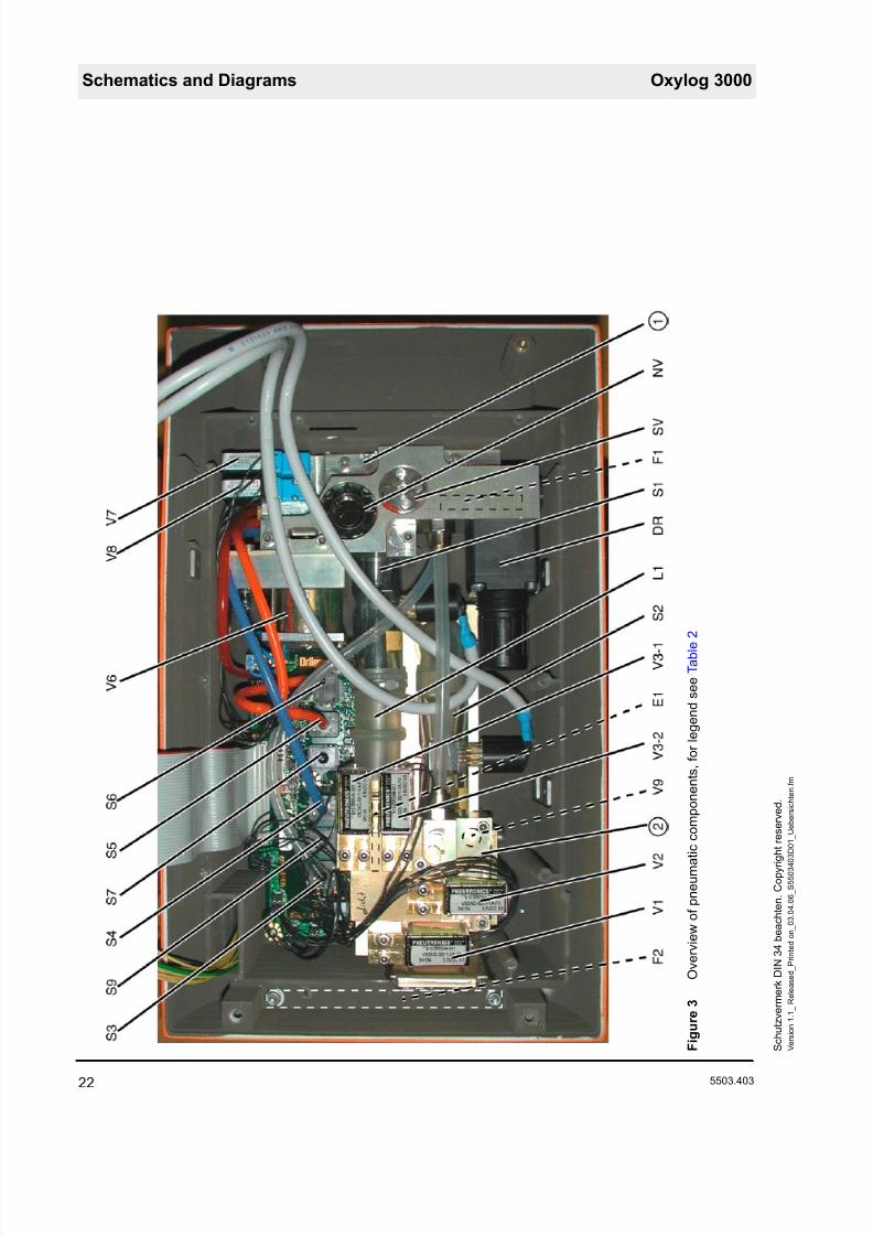
T a b l e 2
L e g e n d F i g u r e 2 a n d F i g u r e 3
I t e m
D e s i g n a t i o n
1
C o n n e c t i o n b l o c k
2
M e t e r i n g b l o
c k
D R
P r e s s u r e r e g
u l a t o r
E 1
E j e c t o r
F 1
F i l t e r i n O 2 c
o m p r e s s e d g a s c o n n e c t i o n
F 2
F i l t e r f o r i n t a
k e a i r
L 1
L 1 e n s u r e s u n i f o r m f l o w
N V
E m e r g e n c y a i r v a l v e
S 1
F l o w s e n s o r
t o m e a s u r e i n t e r n a l i n s p i r a t o r y f l o
w
S 2
F l o w s e n s o r
t o m e a s u r e t h e a m b i e n t a i r i n t a k e
S 3
P r e s s u r e s e n s o r ( P v ) t o m e a s u r e s u p p l y p r e s s
u r e f o r v a l v e s V 1 t o V 3
S 4
P r e s s u r e s e n s o r ( P i n t ) t o m e a s u r e u n i t - i n t e r n a
l p a t i e n t p r e s s u r e
S 5
P r e s s u r e s e n s o r ( P a w ) t o m e a s u r e p r e s s u r e c
l o s e t o p a t i e n t
S 6
P r e s s u r e s e n s o r ( d e l t a P ) t o m e a s u r e d i f f e r e n t i a l p r e s s u r e a t e x t e r n a l f l o w s e n s o r
S 7 a n d S 9
P r e s s u r e s e n s o r s t o m e a s u r e a m b i e n t p r e s s u r e
S 8
E x t e r n a l f l o w
s e n s o r
S V
S a f e t y v a l v e
V 1 t o V 3
M e t e r i n g v a l v e s
V 1 0
V e n t i l a t i o n v a l v e
V 6
P E E P v a l v e
V 7 a n d V 8
S w i t c h i n g v a
l v e s t o c a l i b r a t e p r e s s u r e s e n s o r s
S 5 a n d S 6
V 9
N o n - r e t u r n v
a l v e
8/10/2019 Dräger Oxylog 3000 - Service Manuals
http://slidepdf.com/reader/full/draeger-oxylog-3000-service-manuals 28/69
Schematics and Diagrams Oxylog 3000
22 5503.403
S c h u t z v e r m e r k D I N 3 4 b e a c h t e n . C o p y r i g h t r e s e r v e d .
V e r s i o n 1 . 1_
R e l e a s e d_
P r i n t e d o n_
0 3 . 0 4 . 0 6_
S 5 5 0 3 4 0 3 D 0 1_
U e b e r s i c h t e n
. f m
F i g u r e 3
O v e r v i e w o f p n e u m a t i c c o m p o n e
n t s , f o r l e g e n d s e e T a b l e 2
8/10/2019 Dräger Oxylog 3000 - Service Manuals
http://slidepdf.com/reader/full/draeger-oxylog-3000-service-manuals 29/69
Oxylog 3000 Schematics and Diagrams
5503.403 23
S c h u t z v e r m e r k D I N 3 4 b e a c h t e n . C o p y r i g h t r e s e r v e d .
V e r s i o n 1 . 1_
R e l e a
s e d_
P r i n t e d o n_
0 3 . 0 4 . 0 6_
S 5 5 0 3 4 0 3 D 0 1_
U e b e r s i c h t e n
. f m
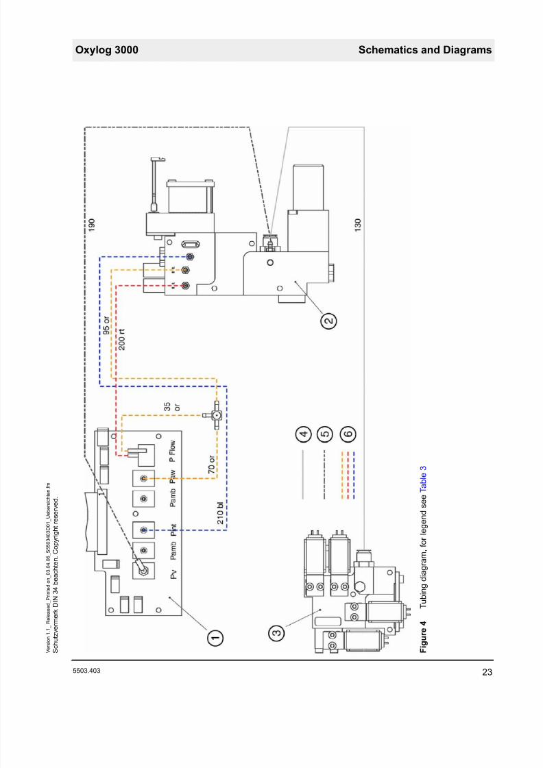
F i g u r e 4
T u b i n g d i a g r a m , f o r l e g e n d s e e T
a b l e 3
8/10/2019 Dräger Oxylog 3000 - Service Manuals
http://slidepdf.com/reader/full/draeger-oxylog-3000-service-manuals 30/69
Schematics and Diagrams Oxylog 3000
24 5503.403
S c h u t z v e r m e r k D I N 3 4 b e a c h t e n . C o p y r i g h t r e s e r v e d .
V e r s i o n 1 . 1_
R e l e a s e d_
P r i n t e d o n_
0 3 . 0 4 . 0 6_
S 5 5 0 3 4 0 3 D 0 1_
U e b e r s i c h t e n
. f m
T a b l e 3
L e g e n d F i g u r e 4
I t e m
D e s i g n a t i o n
1
S e n s o r P C B
2
C o n n e c t i o n b l o c k
3
M e t e r i n g b l o
c k
4
T u b e 4 x 1 P A
E n o t c o l o u r e d ( n c )
5
T u b e 2 x 1 . 5 S i n o t c o l o u r e d ( n c )
6
T u b e 2 x 1 S i
b l u e ( b l ) , r e d ( r d ) , o r a n g e ( o r )
8/10/2019 Dräger Oxylog 3000 - Service Manuals
http://slidepdf.com/reader/full/draeger-oxylog-3000-service-manuals 31/69
Oxylog 3000 Schematics and Diagrams
5503.403 25
S c h u t z v e r m e r k D I N 3 4 b e a c h t e n . C o p y r i g h t r e s e r v e d .
V e r s i o n 1 . 1_
R e l e a
s e d_
P r i n t e d o n_
0 3 . 0 4 . 0 6_
S 5 5 0 3 4 0 3 D 0 1_
U e b e r s i c h t e n
. f m
F i g u r e 5
E l e c t r o n i c s b l o c k d i a g r a m
8/10/2019 Dräger Oxylog 3000 - Service Manuals
http://slidepdf.com/reader/full/draeger-oxylog-3000-service-manuals 32/69
Schematics and Diagrams Oxylog 3000
26 5503.403
S c h u t z v e r m e r k D I N 3 4 b e a c h t e n . C o p y r i g h t r e s e r v e d .
V e r s i o n 1 . 1_
R e l e a s e d_
P r i n t e d o n_
0 3 . 0 4 . 0 6_
S 5 5 0 3 4 0 3 D 0 1_
U e b e r s i c h t e n
. f m
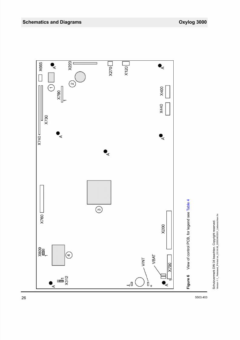
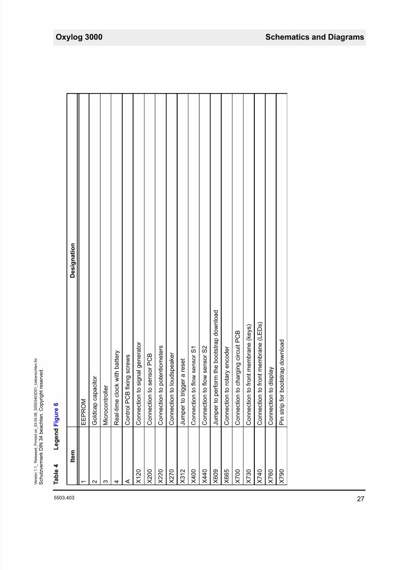
F i g u r e 6
V i e w o f c o n t r o l P C B , f o r l e g e n d s
e e T a b l e 4
8/10/2019 Dräger Oxylog 3000 - Service Manuals
http://slidepdf.com/reader/full/draeger-oxylog-3000-service-manuals 33/69
Oxylog 3000 Schematics and Diagrams
5503.403 27
S c h u t z v e r m e r k D I N 3 4 b e a c h t e n . C o p y r i g h t r e s e r v e d .
V e r s i o n 1 . 1_
R e l e a
s e d_
P r i n t e d o n_
0 3 . 0 4 . 0 6_
S 5 5 0 3 4 0 3 D 0 1_
U e b e r s i c h t e n
. f m
T a b l e 4
L e g e n d F i g u r e 6
I t e m
D e
s i g n a t i o n
1
E E P R O M
2
G o l d c a p c a p a c i t o r
3
M i c r o c o n t r o l l e r
4
R e a l - t i m e c l o c k w i t h b a
t t e r y
A
C o n t r o l P C B f i x i n g s c r e
w s
X 1 2 0
C o n n e c t i o n t o s i g n a l g e
n e r a t o r
X 2 0 0
C o n n e c t i o n t o s e n s o r P
C B
X 2 2 0
C o n n e c t i o n t o p o t e n t i o m e t e r s
X 2 7 0
C o n n e c t i o n t o l o u d s p e a
k e r
X 3 1 2
J u m p e r t o t r i g g e r a r e s e t
X 4 0 0
C o n n e c t i o n t o f l o w s e n s o r S 1
X 4 4 0
C o n n e c t i o n t o f l o w s e n s o r S 2
X 6 0 9
J u m p e r t o p e r f o r m t h e b o o t s t r a p d o w n l o a d
X 6 6 5
C o n n e c t i o n t o r o t a r y e n
c o d e r
X 7 0 0
C o n n e c t i o n t o c h a r g i n g
c i r c u i t P C B
X 7 3 0
C o n n e c t i o n t o f r o n t m e m b r a n e ( k e y s )
X 7 4 0
C o n n e c t i o n t o f r o n t m e m b r a n e ( L E D s )
X 7 6 0
C o n n e c t i o n t o d i s p l a y
X 7 9 0
P i n s t r i p f o r b o o t s t r a p d
o w n l o a d

8/10/2019 Dräger Oxylog 3000 - Service Manuals
http://slidepdf.com/reader/full/draeger-oxylog-3000-service-manuals 34/69
Schematics and Diagrams Oxylog 3000
28 5503.403
S c h u t z v e r m e r k D I N 3 4 b e a c h t e n . C o p y r i g h t r e s e r v e d .
V e r s i o n 1 . 1_
R e l e a s e d_
P r i n t e d o n_
0 3 . 0 4 . 0 6_
S 5 5 0 3 4 0 3 D 0 1_
U e b e r s i c h t e n
. f m

8/10/2019 Dräger Oxylog 3000 - Service Manuals
http://slidepdf.com/reader/full/draeger-oxylog-3000-service-manuals 35/69
Annex
Parts catalog
Test List
Technical Information

8/10/2019 Dräger Oxylog 3000 - Service Manuals
http://slidepdf.com/reader/full/draeger-oxylog-3000-service-manuals 36/69
8/10/2019 Dräger Oxylog 3000 - Service Manuals
http://slidepdf.com/reader/full/draeger-oxylog-3000-service-manuals 37/69
Parts catalog
Oxylog 3000
Because you care
5503.403
Revision: 2006-02-01 11:37:13

8/10/2019 Dräger Oxylog 3000 - Service Manuals
http://slidepdf.com/reader/full/draeger-oxylog-3000-service-manuals 38/69
8/10/2019 Dräger Oxylog 3000 - Service Manuals
http://slidepdf.com/reader/full/draeger-oxylog-3000-service-manuals 39/69
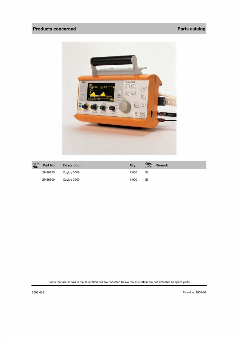
Products concerned Parts catalog
ItemNo. Part No. Description Qty. Qty.
unit Remark
2M86955 Oxylog 3000 1.000 St
2M86300 Oxylog 3000 1.000 St
Revision: 2006-02-01 11:37:135503.403
Items that are shown in the illustration but are not listed below the illustration are not available as spare parts
8/10/2019 Dräger Oxylog 3000 - Service Manuals
http://slidepdf.com/reader/full/draeger-oxylog-3000-service-manuals 40/69
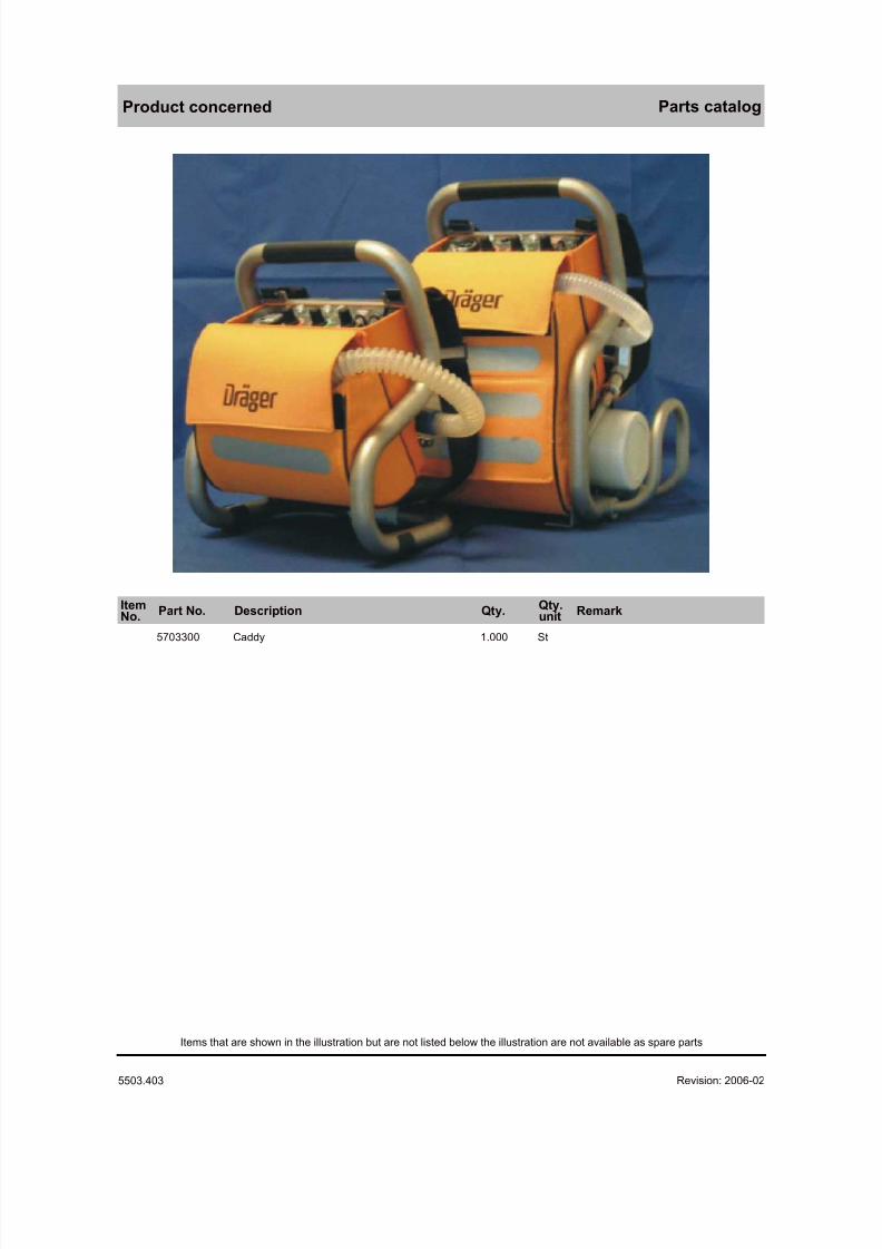
Product concerned Parts catalog
ItemNo. Part No. Description Qty. Qty.
unit Remark
5703300 Caddy 1.000 St
Revision: 2006-02-01 11:37:135503.403
Items that are shown in the illustration but are not listed below the illustration are not available as spare parts
8/10/2019 Dräger Oxylog 3000 - Service Manuals
http://slidepdf.com/reader/full/draeger-oxylog-3000-service-manuals 41/69
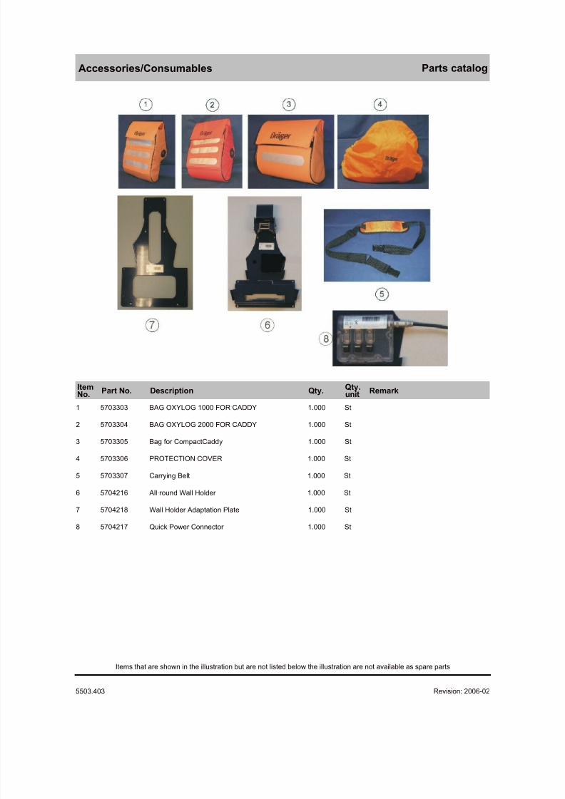
Accessories/Consumables Parts catalog
ItemNo. Part No. Description Qty. Qty.
unit Remark
1 5703303 BAG OXYLOG 1000 FOR CADDY 1.000 St
2 5703304 BAG OXYLOG 2000 FOR CADDY 1.000 St
3 5703305 Bag for CompactCaddy 1.000 St
4 5703306 PROTECTION COVER 1.000 St
5 5703307 Carrying Belt 1.000 St
6 5704216 All-round Wall Holder 1.000 St
7 5704218 Wall Holder Adaptation Plate 1.000 St
8 5704217 Quick Power Connector 1.000 St
Revision: 2006-02-01 11:37:135503.403
Items that are shown in the illustration but are not listed below the illustration are not available as spare parts
8/10/2019 Dräger Oxylog 3000 - Service Manuals
http://slidepdf.com/reader/full/draeger-oxylog-3000-service-manuals 42/69
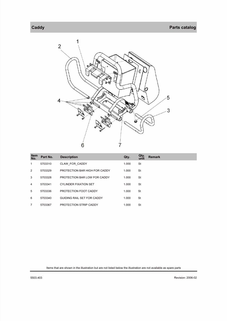
Caddy Parts catalog
ItemNo. Part No. Description Qty. Qty.
unit Remark
1 5703310 CLAW_FOR_CADDY 1.000 St
2 5703329 PROTECTION BAR HIGH FOR CADDY 1.000 St
3 5703328 PROTECTION BAR LOW FOR CADDY 1.000 St
4 5703341 CYLINDER FIXATION SET 1.000 St
5 5703336 PROTECTION FOOT CADDY 1.000 St
6 5703340 GUIDING RAIL SET FOR CADDY 1.000 St
7 5703367 PROTECTION STRIP CADDY 1.000 St
Revision: 2006-02-01 11:37:135503.403
Items that are shown in the illustration but are not listed below the illustration are not available as spare parts
8/10/2019 Dräger Oxylog 3000 - Service Manuals
http://slidepdf.com/reader/full/draeger-oxylog-3000-service-manuals 43/69
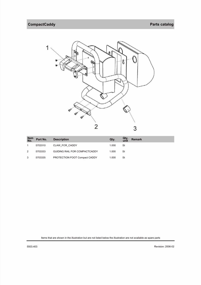
CompactCaddy Parts catalog
ItemNo. Part No. Description Qty. Qty.
unit Remark
1 5703310 CLAW_FOR_CADDY 1.000 St
2 5703333 GUIDING RAIL FOR COMPACTCADDY 1.000 St
3 5703335 PROTECTION FOOT Compact CADDY 1.000 St
Revision: 2006-02-01 11:37:135503.403
Items that are shown in the illustration but are not listed below the illustration are not available as spare parts
8/10/2019 Dräger Oxylog 3000 - Service Manuals
http://slidepdf.com/reader/full/draeger-oxylog-3000-service-manuals 44/69
Front Parts catalog
ItemNo. Part No. Description Qty. Qty.
unit Remark
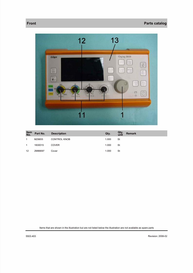
1 M29655 CONTROL KNOB 1.000 St
1 1830015 COVER 1.000 St
12 2M86697 Cover 1.000 St
Revision: 2006-02-01 11:37:135503.403
Items that are shown in the illustration but are not listed below the illustration are not available as spare parts
8/10/2019 Dräger Oxylog 3000 - Service Manuals
http://slidepdf.com/reader/full/draeger-oxylog-3000-service-manuals 45/69
Pneumatic Parts catalog
ItemNo. Part No. Description Qty. Qty.
unit Remark
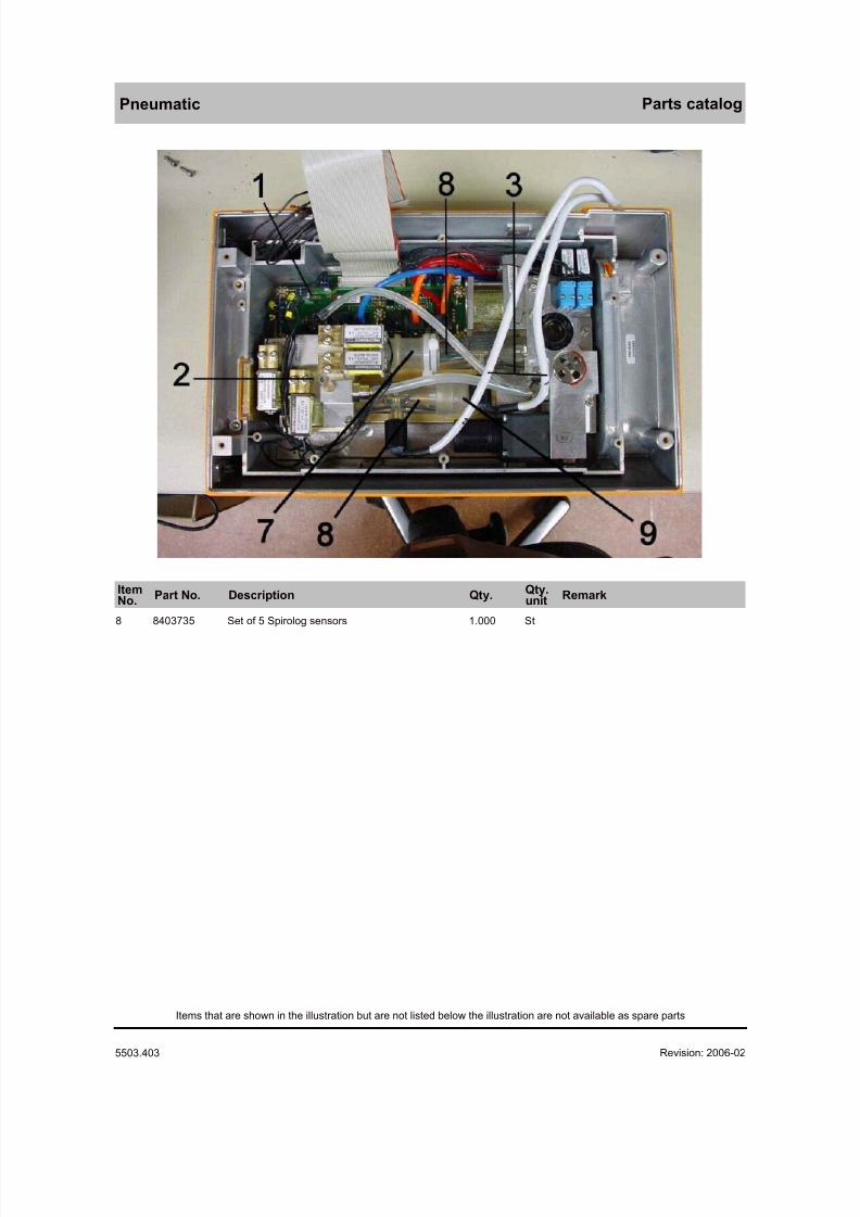
8 8403735 Set of 5 Spirolog sensors 1.000 St
Revision: 2006-02-01 11:37:135503.403
Items that are shown in the illustration but are not listed below the illustration are not available as spare parts
8/10/2019 Dräger Oxylog 3000 - Service Manuals
http://slidepdf.com/reader/full/draeger-oxylog-3000-service-manuals 46/69
Pneumatic Parts catalog
ItemNo. Part No. Description Qty. Qty.
unit Remark
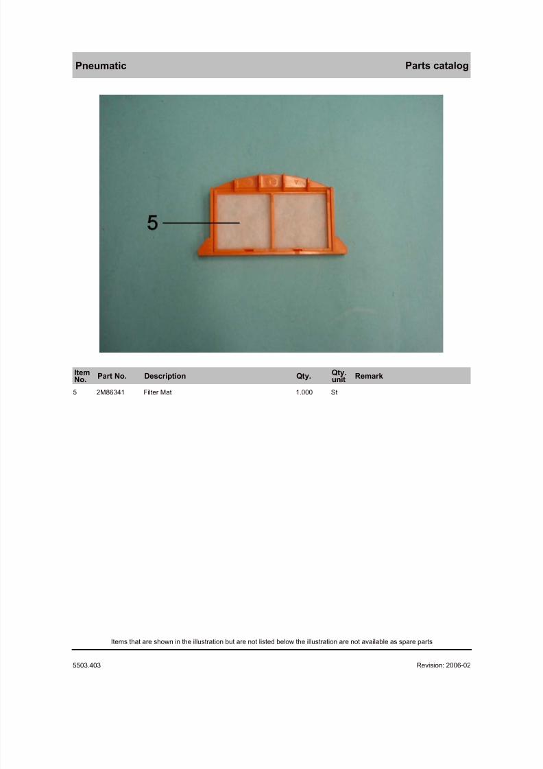
5 2M86341 Filter Mat 1.000 St
Revision: 2006-02-01 11:37:135503.403
Items that are shown in the illustration but are not listed below the illustration are not available as spare parts
8/10/2019 Dräger Oxylog 3000 - Service Manuals
http://slidepdf.com/reader/full/draeger-oxylog-3000-service-manuals 47/69
Dosing block Parts catalog
ItemNo. Part No. Description Qty. Qty.
unit Remark
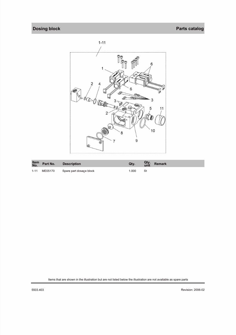
1-11 ME05170 Spare part dosage block 1.000 St
Revision: 2006-02-01 11:37:135503.403
Items that are shown in the illustration but are not listed below the illustration are not available as spare parts
8/10/2019 Dräger Oxylog 3000 - Service Manuals
http://slidepdf.com/reader/full/draeger-oxylog-3000-service-manuals 48/69
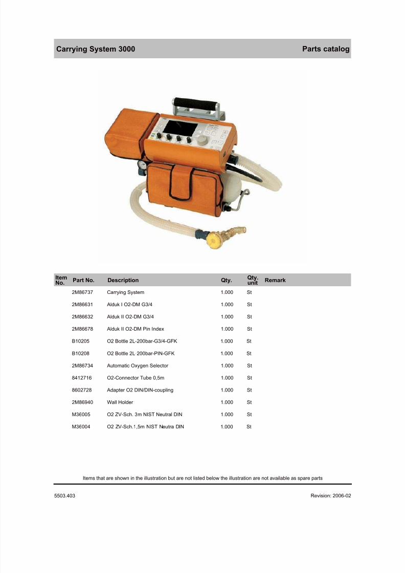
Carrying System 3000 Parts catalog
ItemNo. Part No. Description Qty. Qty.
unit Remark
2M86737 Carrying System 1.000 St
2M86631 Alduk I O2-DM G3/4 1.000 St
2M86632 Alduk II O2-DM G3/4 1.000 St
2M86678 Alduk II O2-DM Pin Index 1.000 St
B10205 O2 Bottle 2L-200bar-G3/4-GFK 1.000 St
B10208 O2 Bottle 2L-200bar-PIN-GFK 1.000 St
2M86734 Automatic Oxygen Selector 1.000 St
8412716 O2-Connector Tube 0,5m 1.000 St
8602728 Adapter O2 DIN/DIN-coupling 1.000 St
2M86940 Wall Holder 1.000 St
M36005 O2 ZV-Sch. 3m NIST Neutral DIN 1.000 St
M36004 O2 ZV-Sch.1,5m NIST Neutra DIN 1.000 St
Revision: 2006-02-01 11:37:135503.403
Items that are shown in the illustration but are not listed below the illustration are not available as spare parts

8/10/2019 Dräger Oxylog 3000 - Service Manuals
http://slidepdf.com/reader/full/draeger-oxylog-3000-service-manuals 49/69
8/10/2019 Dräger Oxylog 3000 - Service Manuals
http://slidepdf.com/reader/full/draeger-oxylog-3000-service-manuals 50/69
Description Part No.
90° angled connector 8412235
AC/DC power pack 2M86730
Adapter O2 DIN/DIN-coupling 8602728
Alduk I O2-DM G3/4 2M86631
Alduk I O2-DM G3/4 2M86631
Alduk I O2-DM Pin Index 2M86677
Alduk II O2-DM G3/4 2M86632
Alduk II O2-DM G3/4 2M86632
Alduk II O2-DM Pin Index 2M86678
Alduk II O2-DM Pin Index 2M86678
All-round Wall Holder 5704216
Automatic Oxygen Selector 2M86734
Bag for CompactCaddy 5703305
BAG OXYLOG 1000 FOR CADDY 5703303
BAG OXYLOG 2000 FOR CADDY 5703304
Breathing valve Oxylog 2000 8412001
Caddy 5703300
Carrying Belt 5703307
Carrying System 2M86737
CLAW_FOR_CADDY 5703310
CLAW_FOR_CADDY 5703310
CONTROL KNOB M29655
CORRUGATED HOSE 8402041
COVER 1830015
Cover 2M86697
CYLINDER FIXATION SET 5703341
DC/DC Converter 2M86731
Equipment Holder 2M86900
External charge station 2M86729
Filter Mat 2M86341
Flowsensor 8412034
GUIDING RAIL FOR COMPACTCADDY 5703333
GUIDING RAIL SET FOR CADDY 5703340
IfU Caddy und CompactCaddy me 9038011
IfU Carrying System 3000 me 9037752
IfU Equipment Holder 3000 me 9037753
IfU Oxylog 3000 de 9037170
O2 Bottle 2L-200bar-G3/4-GFK B10205
O2 Bottle 2L-200bar-PIN-GFK B10208
O2 ZV-Sch. 3m NIST Neutral DIN M36005
O2 ZV-Sch.1,5m NIST Neutra DIN M36004
O2-AIR CONNECT.HOSE 3M(BLACK) M29245
O2-AIR CONNECT.HOSE 5M (BLACK) M29265
Description Part No.
O2-AIR-CONNECT.HOSE 1,5(BLACK) M29285
O2-Connector Tube 0,5m 8412716
O2/AIR-HOSE NIST 1,5MDIN PROBE M34410
O2/AIR-HOSE NIST 3M DIN PROBE M34411
O2/AIR-HOSE NIST 5M DIN PROBE M34412
Option 100% O2 ME05053
Option ASB/PS ME05055
Option BIPAP/PCV+ ME05056
Option O2-Blender ME05054
Option O2-Inhalation ME05052
Oxylog 3000 2M86300
Oxylog 3000 2M86955
Power cable 10A, 3m, grey, USA/J 1841793
Power cable Australia 3m,10A,C13L 1844350
Power cable DK, 3 m, 10 A 1844342
Power cable Great Britian 3m black 1844369
POWERCORD CH 3M 1844377
PROTECTION BAR HIGH FOR CADDY 5703329
PROTECTION BAR LOW FOR CADDY 5703328
PROTECTION COVER 5703306
PROTECTION FOOT CADDY 5703336
PROTECTION FOOT Compact CADDY 5703335
PROTECTION STRIP CADDY 5703367
Quick Power Connector 5704217
Resp.hose w.flow meas.cable 8412068
Respiration hose 3 m 8412913
SET 12 STAND. CONE A PLASTIC 8403685
Set of 5 Spirolog sensors 8403735
SOCKET M20101
Spare part dosage block ME05170
SUPPLY MAIN, 3M 1824481
TEST LUNG 8403201
Vent hose disp Oxylog 3000 set 2M86841
Wall Holder 2M86940
Wall Holder Adaptation Plate 5704218
Revision: 2006-02-01 11:37:13
Parts catalog
5503.403
Oxylog 3000 Summary
8/10/2019 Dräger Oxylog 3000 - Service Manuals
http://slidepdf.com/reader/full/draeger-oxylog-3000-service-manuals 51/69
5503.403 Oxylog 3000 Released 2002-03-07 A l l r i g h t s r e s e r v
e d . C o p y r i g h t r e s e r v e d .
K 5 5 0 3 4 0 3 T L 2_
D e c k b l a t t . f m 1 7 . 1 1 . 0 5
Test List (TL)
Oxylog 3000
Notes on field of application:
This test list can be processed with standard commercially available test aids and tools, but
does not replace the inspections and maintenance work carried out by the manufacturer.
Tests marked with the symbol '(√)' are listed in the 'Test list report“ and can be documented
there.

8/10/2019 Dräger Oxylog 3000 - Service Manuals
http://slidepdf.com/reader/full/draeger-oxylog-3000-service-manuals 52/69
5503.403 Oxylog 3000 Released 2002-03-07 A l l r i g h t s r e s e r v
e d . C o p y r i g h t r e s e r v e d .
K 5 5 0 3 4 0 3 T L 1 I V Z . f m
1 7 . 1 1 . 0 5
I
Contents
1 Device configuration .................................................................................................................... 11.1 Serial number (SN)....................................................................................................... 11.2 Software ....................................................................................................................... 1
2 Electrical safety............................................................................................................................ 22.1 Oxylog 3000 - not applicable - ...................................................................................... 22.2 AC/DC power pack....................................................................................................... 2
3 Function and condition test.......................................................................................................... 33.1 Accompanying documentation ..................................................................................... 3
3.2 Visual check ................................................................................................................. 3
3.3 Safety valve .................................................................................................................. 3
3.4 Unit test ........................................................................................................................ 4
3.5 Buttons and potentiometer ........................................................................................... 4
3.6 Loudspeaker, buzzer, LEDs and display ...................................................................... 4
3.7 Voltage supply .............................................................................................................. 53.8 Supply pressure/emergency air valve .......................................................................... 6
3.9 Ventilation..................................................................................................................... 73.10 Unit handover ............................................................................................................... 9
4 Test Equipment .......................................................................................................................... 104.1 List of test aids .......................................................................................................... 10
5 Annex......................................................................................................................................... 115.1 Access to Customer Service mode (CSM) ................................................................. 11
8/10/2019 Dräger Oxylog 3000 - Service Manuals
http://slidepdf.com/reader/full/draeger-oxylog-3000-service-manuals 53/69
8/10/2019 Dräger Oxylog 3000 - Service Manuals
http://slidepdf.com/reader/full/draeger-oxylog-3000-service-manuals 54/69
5503.403 Oxylog 3000 Released 2002-03-07 A l l r i g h t s r e s e r v
e d . C o p y r i g h t r e s e r v e d .
K 5 5 0 3 4 0 3 T L 1_
T e s t l i s t e . f m 1 7 . 1 1 . 0 5
2/11
2 Electrical safety
2.1 Oxylog 3000 - not applicable -
2.2 AC/DC power pack
The AC/DC power pack is categorized as protection class I (safety
insulated). Measure to VDE 0751 or IEC 601.
2.2.1 Equivalent device leakage current test
1. Connect output of AC/DC power pack to Oxylog 3000.
(√) 2.2.1.1 Initial measured value [ _____ µ A]
Import the initial measured value from the old report into the new one. The
initial measured value may be maximum 500 µ A.
(√) 2.2.1.2 Current value [ _____ µ A]
The current value may exceed the initial measured value by max. 50 %
and at the same time must be ≤500 µ A.
8/10/2019 Dräger Oxylog 3000 - Service Manuals
http://slidepdf.com/reader/full/draeger-oxylog-3000-service-manuals 55/69
8/10/2019 Dräger Oxylog 3000 - Service Manuals
http://slidepdf.com/reader/full/draeger-oxylog-3000-service-manuals 56/69
8/10/2019 Dräger Oxylog 3000 - Service Manuals
http://slidepdf.com/reader/full/draeger-oxylog-3000-service-manuals 57/69
5503.403 Oxylog 3000 Released 2002-03-07 A l l r i g h t s r e s e r v
e d . C o p y r i g h t r e s e r v e d .
K 5 5 0 3 4 0 3 T L 1_
T e s t l i s t e . f m 1 7 . 1 1 . 0 5
5/11
3.7 Voltage supply
1. Connect unit to power and to O2 compressed gas supply.
2. Connect ventilation tube and ventilation valve to flow sensor and
flowmeter tubes.
3. Connect test thorax, elbow adapter and flow sensor.
(√) 3.7.1 External power supply
The external power LED lights up green.
[OK]
The charge indicator LED of the internal replaceable battery lights up in
the following colours:
− Yellow: when the replaceable battery is charging− Green: when the battery is fully charged
− Red: when no functional battery is inserted or the battery cannot be
charged, such as because the unit is being used outside the
temperature range of 0 to 35 °C.
[OK]
(√) 3.7.2 Internal replaceable battery
1. Switch on unit.
2. Set ventilation mode IPPV.3. Remove internal replaceable battery.
− The unit continues ventilating.
− The display shows the message "No battery".
− The charge indicator LED is lit red.
− An acoustic alarm sounds.
[OK]
4. Refit the internal replaceable battery.
− The charge indicator LED is lit green.− The acoustic alarm is deactivated.
5. Press the "Alarm Reset" button.
The "No battery" message is no longer displayed.
[OK]
6. Remove external power supply.
The unit continues ventilating.
− The external power LED is unlit.
− The internal replaceable battery charge indicator LED is unlit.
8/10/2019 Dräger Oxylog 3000 - Service Manuals
http://slidepdf.com/reader/full/draeger-oxylog-3000-service-manuals 58/69
5503.403 Oxylog 3000 Released 2002-03-07 A l l r i g h t s r e s e r v
e d . C o p y r i g h t r e s e r v e d .
K 5 5 0 3 4 0 3 T L 1_
T e s t l i s t e . f m 1 7 . 1 1 . 0 5
6/11
− An acoustic alarm sounds.
− The display shows the message "Battery operating".
[OK]7. Press the "Alarm Reset" button.
The "Battery operating" message is no longer displayed.
[OK]
8. Remove internal replaceable battery.
− Ventilation stops.
− An acoustic alarm sounds for at least 7 seconds.
[OK]
9. Refit the internal replaceable battery.
10. Connect the external power supply.
Ventilation is resumed with the previous settings.
[OK]
(√) 3.8 Supply pressure/emergency air valve
1. Connect unit to power and to O2 compressed gas supply.
2. Connect ventilation tube and ventilation valve to flow sensor and
flowmeter tubes.
3. Connect test thorax, elbow adapter and flow sensor.4. Set ventilation mode IPPV.
5. Remove compressed gas supply.
− An acoustic alarm sounds.
− The display shows the message "!!!Supply pressure low".
− The red alarm LED lights up.
− Ventilation stops.
[OK]
6. Simulate spontaneous breathing with the test thorax.
Ventilation through the emergency air valve is possible.
[OK]
7. Connect the compressed gas supply.
− The acoustic alarm stops.
− The red alarm LED is no longer lit.
− Ventilation is resumed with the previous settings.
[OK]
8. Press the "Alarm Reset" button.
8/10/2019 Dräger Oxylog 3000 - Service Manuals
http://slidepdf.com/reader/full/draeger-oxylog-3000-service-manuals 59/69
5503.403 Oxylog 3000 Released 2002-03-07 A l l r i g h t s r e s e r v
e d . C o p y r i g h t r e s e r v e d .
K 5 5 0 3 4 0 3 T L 1_
T e s t l i s t e . f m 1 7 . 1 1 . 0 5
7/11
The "!!!Supply pressure low" message is no longer displayed.
[OK]
3.9 Ventilation
(√) 3.9.1 Volume-controlled ventilation
1. Connect unit to power and to O2 compressed gas supply.
2. Connect ventilation tube and ventilation valve to flow sensor and
flowmeter tubes.
3. Connect test specimens (breathing bag and catheter socket) to flow
sensor with elbow adapter.
4. Make the following settings:
− Ventilation mode = IPPV
− Frequency = 10 1/min
− Alarm limit Pmax = 60 mbar
− PEEP = 5 mbar
− O2 = 60 Vol.%
− I/E = 1:1
− TPlat = 50%
− Trigger = off
− VT = 200 mL
5. Press the "Values" button to select the measured values MV and VTE.
The displayed MV is in the range 1.3 L/min to 2.3 L/min.
[OK]
6. Set VT to 500 mL.
The displayed MV is in the range 3,7 L/min to 5,3 L/min.
[OK]
7. Set VT to 1000 mL.
The displayed MV is in the range 8 L/min to 10 L/min.
[OK]
(√) 3.9.2 Pressure-controlled ventilation
1. Remove test specimens and connect test thorax in their place.
2. Make the following settings:
− Ventilation mode = BIPAP
− Frequency = 6 1/min
− Alarm limit Pmax = 60 mbar
8/10/2019 Dräger Oxylog 3000 - Service Manuals
http://slidepdf.com/reader/full/draeger-oxylog-3000-service-manuals 60/69
5503.403 Oxylog 3000 Released 2002-03-07 A l l r i g h t s r e s e r v
e d . C o p y r i g h t r e s e r v e d .
K 5 5 0 3 4 0 3 T L 1_
T e s t l i s t e . f m 1 7 . 1 1 . 0 5
8/11
− PEEP = 5 mbar
− Pinsp = 25 mbar
−Tinsp = 5 s
− O2 = 60 Vol.%
− NIV = off
− Trigger = 15 L/min
− Ramp = standard (middle curve)
Wait a few breaths for the values to stabilize.
The displayed PEEP value is in the range 3 mbar to 7 mbar.
[OK]
Ppeak is in the range 23 mbar to 27 mbar.[OK]
(√) 3.9.3 Trigger function
1. Make the following settings:
− Ventilation mode = SIMV
− Frequency = 5 1/min
− PEEP = 10 mbar
− Tinsp = 1 s− VT = 500 mL
− Alarm limit Pmax = 60 mbar
− O2 = 60 Vol.%
− Flow trigger = 3 L/min
− Flow ramp = not applicable, or standard
The test thorax inflates to a PEEP pressure of 10 mbar.
[OK]
No self-triggering occurs.
[OK]
The message "O2 setting not possible" may appear. The message can be
ignored.
2. Trigger using the test thorax.
8/10/2019 Dräger Oxylog 3000 - Service Manuals
http://slidepdf.com/reader/full/draeger-oxylog-3000-service-manuals 61/69
5503.403 Oxylog 3000 Released 2002-03-07 A l l r i g h t s r e s e r v
e d . C o p y r i g h t r e s e r v e d .
K 5 5 0 3 4 0 3 T L 1_
T e s t l i s t e . f m 1 7 . 1 1 . 0 5
9/11
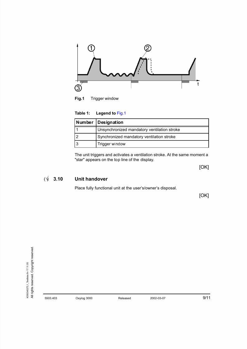
Fig.1 Trigger window
Table 1: Legend to Fig.1
The unit triggers and activates a ventilation stroke. At the same moment a
"star" appears on the top line of the display.
[OK]
(√) 3.10 Unit handover
Place fully functional unit at the user’s/owner’s disposal.
[OK]
Number Designation
1 Unsynchronized mandatory ventilation stroke
2 Synchronized mandatory ventilation stroke
3 Trigger window
8/10/2019 Dräger Oxylog 3000 - Service Manuals
http://slidepdf.com/reader/full/draeger-oxylog-3000-service-manuals 62/69
5503.403 Oxylog 3000 Released 2002-03-07 A l l r i g h t s r e s e r v
e d . C o p y r i g h t r e s e r v e d .
K 5 5 0 3 4 0 3 T L 1_
T e s t l i s t e . f m 1 7 . 1 1 . 0 5
10/11
4 Test Equipment
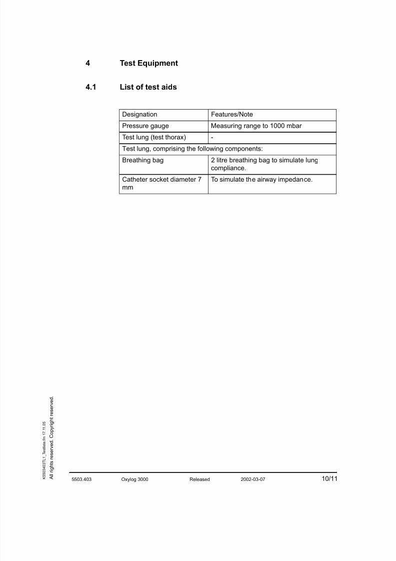
4.1 List of test aids
Designation Features/Note
Pressure gauge Measuring range to 1000 mbar
Test lung (test thorax) -
Test lung, comprising the following components:
Breathing bag 2 litre breathing bag to simulate lung
compliance.
Catheter socket diameter 7mm
To simulate the airway impedance.
8/10/2019 Dräger Oxylog 3000 - Service Manuals
http://slidepdf.com/reader/full/draeger-oxylog-3000-service-manuals 63/69
5503.403 Oxylog 3000 Released 2002-03-07 A l l r i g h t s r e s e r v
e d . C o p y r i g h t r e s e r v e d .
K 5 5 0 3 4 0 3 T L 1_
T e s t l i s t e . f m 1 7 . 1 1 . 0 5
11/11
5 Annex
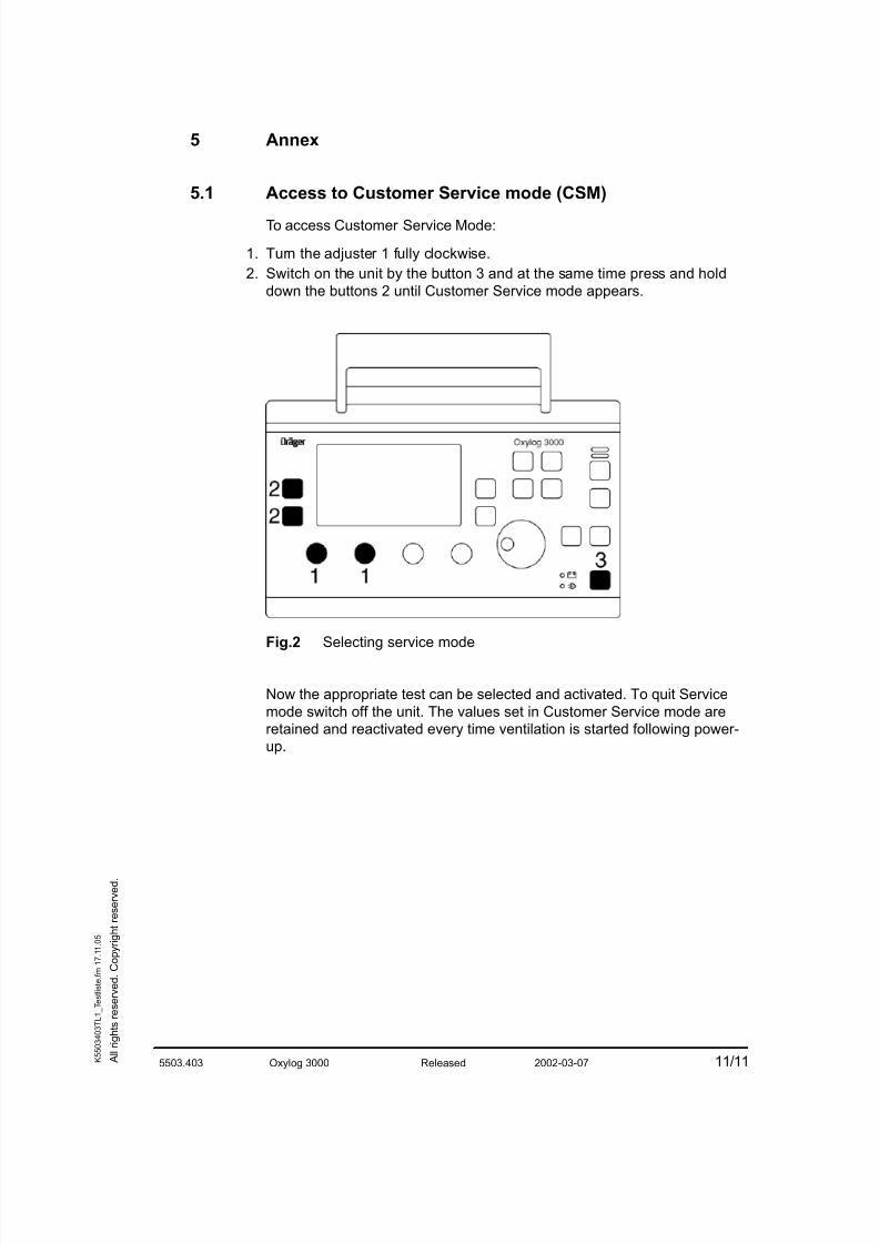
5.1 Access to Customer Service mode (CSM)To access Customer Service Mode:
1. Turn the adjuster 1 fully clockwise.
2. Switch on the unit by the button 3 and at the same time press and hold
down the buttons 2 until Customer Service mode appears.
Fig.2 Selecting service mode
Now the appropriate test can be selected and activated. To quit Service
mode switch off the unit. The values set in Customer Service mode are
retained and reactivated every time ventilation is started following power-
up.
8/10/2019 Dräger Oxylog 3000 - Service Manuals
http://slidepdf.com/reader/full/draeger-oxylog-3000-service-manuals 64/69
Test List Report Oxylog 3000
Test List Edition: 2002-03-07
Installation site: __________
Supply tested and fully functional device to owner/user.
Date: Name/Signature: 1/1
OK Result OK Result
A l l r i g h t s r e s e r v e d . C o p y r i g h t r e s e r v e d .
K 5 5 0 3 4 0 3 T L 1 E A L . f m 1 7
. 1 1 . 0 5
1 Device configuration1.1 Serial number (SN)
( ) 1.1.1 Oxylog 3000 [ __________ ]
1.2 Software
( ) 1.2.1 Software version [ __________ ]
2 Electrical safety
2.2 AC/DC power pack
2.2.1 Equivalent device leakage current test
( ) 2.2.1.1 Initial measured value [ _____ µ A]
( ) 2.2.1.2 Current value [ _____ µ A]
3 Function and condition test
( ) 3.1 Accompanying documentation
( ) 3.2 Visual check
( ) 3.3 Safety valve
( ) 3.4 Unit test
( ) 3.5 Buttons and potentiometer
( ) 3.6 Loudspeaker, buzzer, LEDs and display
3.7 Voltage supply
( ) 3.7.1 External power supply
( ) 3.7.2 Internal replaceable battery
( ) 3.8 Supply pressure/emergency air valve
3.9 Ventilation
( ) 3.9.1 Volume-controlled ventilation
( ) 3.9.2 Pressure-controlled ventilation
( ) 3.9.3 Trigger function
( ) 3.10 Unit handover
8/10/2019 Dräger Oxylog 3000 - Service Manuals
http://slidepdf.com/reader/full/draeger-oxylog-3000-service-manuals 65/69
Page 1 of 3
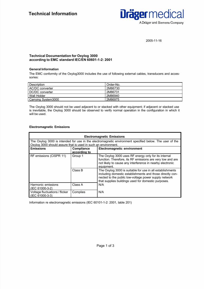
Technical Information
Technical Documentation for Oxylog 3000according to EMC standard IEC/EN 60601-1-2: 2001
General Information
The EMC conformity of the Oxylog3000 includes the use of following external cables, transducers and acces-sories:
Description Order-No.
AC/DC converter 2M86730
DC/DC converter 2M86731Wall Holder 2M86940
Carrying System3000 2M86975
The Oxylog 3000 should not be used adjacent to or stacked with other equipment; if adjacent or stacked useis inevitable, the Oxylog 3000 should be observed to verify normal operation in the configuration in which itwill be used.
Electromagnetic Emissions
Electromagnetic Emissions
The Oxylog 3000 is intended for use in the electromagnetic environment specified below. The user of theOxylog 3000 should assure that is used in such an environment.
Emissions Complianceaccording to
Electromagnetic environment
RF emissions (CISPR 11) Group 1 The Oxylog 3000 uses RF energy only for its internalfunction. Therefore, its RF emissions are very low and arenot likely to cause any interference in nearby electronicequipment.
Class B The Oxylog 3000 is suitable for use in all establishmentsincluding domestic establishments and those directly con-nected to the public low-voltage power supply networkthat supplies buildings used for domestic purposes.
Harmonic emissions(IEC 61000-3-2)
Class A N/A
Voltage fluctuations / flicker(IEC 61000-3-3)
Complies N/A
Information re electromagnetic emissions (IEC 60101-1-2: 2001, table 201)
2005-11-16
8/10/2019 Dräger Oxylog 3000 - Service Manuals
http://slidepdf.com/reader/full/draeger-oxylog-3000-service-manuals 66/69
Page 2 of 3
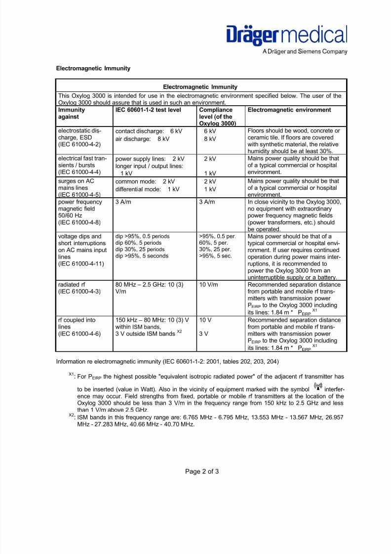
Electromagnetic Immunity
Electromagnetic ImmunityThis Oxylog 3000 is intended for use in the electromagnetic environment specified below. The user of theOxylog 3000 should assure that is used in such an environment.
Immunityagainst
IEC 60601-1-2 test level Compliancelevel (of theOxylog 3000)
Electromagnetic environment
electrostatic dis-charge, ESD(IEC 61000-4-2)
contact discharge: 6 kV
air discharge: 8 kV
6 kV
8 kV
Floors should be wood, concrete orceramic tile. If floors are coveredwith synthetic material, the relativehumidity should be at least 30%.
electrical fast tran-sients / bursts(IEC 61000-4-4)
power supply lines: 2 kV
longer input / output lines:
1 kV
2 kV
1 kV
Mains power quality should be thatof a typical commercial or hospitalenvironment.
surges on ACmains lines(IEC 61000-4-5)
common mode: 2 kV
differential mode: 1 kV
2 kV
1 kV
Mains power quality should be thatof a typical commercial or hospitalenvironment.
power frequencymagnetic field50/60 Hz(IEC 61000-4-8)
3 A/m 3 A/m In close vicinity to the Oxylog 3000,no equipment with extraordinarypower frequency magnetic fields(power transformers, etc.) shouldbe operated.
voltage dips andshort interruptionson AC mains inputlines
(IEC 61000-4-11)
dip >95%, 0.5 periods
dip 60%, 5 periods
dip 30%, 25 periods
dip >95%, 5 seconds
>95%, 0.5 per.60%, 5 per.30%, 25 per.>95%, 5 sec.
Mains power should be that of atypical commercial or hospital envi-ronment. If user requires continuedoperation during power mains inter-
ruptions, it is recommended topower the Oxylog 3000 from anuninterruptible supply or a battery.
radiated rf(IEC 61000-4-3)
80 MHz – 2.5 GHz: 10 (3)V/m
10 V/m Recommended separation distancefrom portable and mobile rf trans-mitters with transmission powerPEIRP to the Oxylog 3000 including
its lines: 1.84 m * PEIRPX1
rf coupled intolines(IEC 61000-4-6)
150 kHz – 80 MHz: 10 (3) Vwithin ISM bands,
3 V outside ISM bandsX2
10 V
3 V
Recommended separation distancefrom portable and mobile rf trans-mitters with transmission powerPEIRP to the Oxylog 3000 including
its lines: 1.84 m * PEIRPX1
Information re electromagnetic immunity (IEC 60601-1-2: 2001, tables 202, 203, 204)
X1: For PEIRP the highest possible "equivalent isotropic radiated power" of the adjacent rf transmitter has
to be inserted (value in Watt). Also in the vicinity of equipment marked with the symbol interfer-ence may occur. Field strengths from fixed, portable or mobile rf transmitters at the location of theOxylog 3000 should be less than 3 V/m in the frequency range from 150 kHz to 2.5 GHz and lessthan 1 V/m above 2.5 GHz.
X2: ISM bands in this frequency range are: 6.765 MHz - 6.795 MHz, 13.553 MHz - 13.567 MHz, 26.957MHz - 27.283 MHz, 40.66 MHz - 40.70 MHz.
8/10/2019 Dräger Oxylog 3000 - Service Manuals
http://slidepdf.com/reader/full/draeger-oxylog-3000-service-manuals 67/69
Page 3 of 3
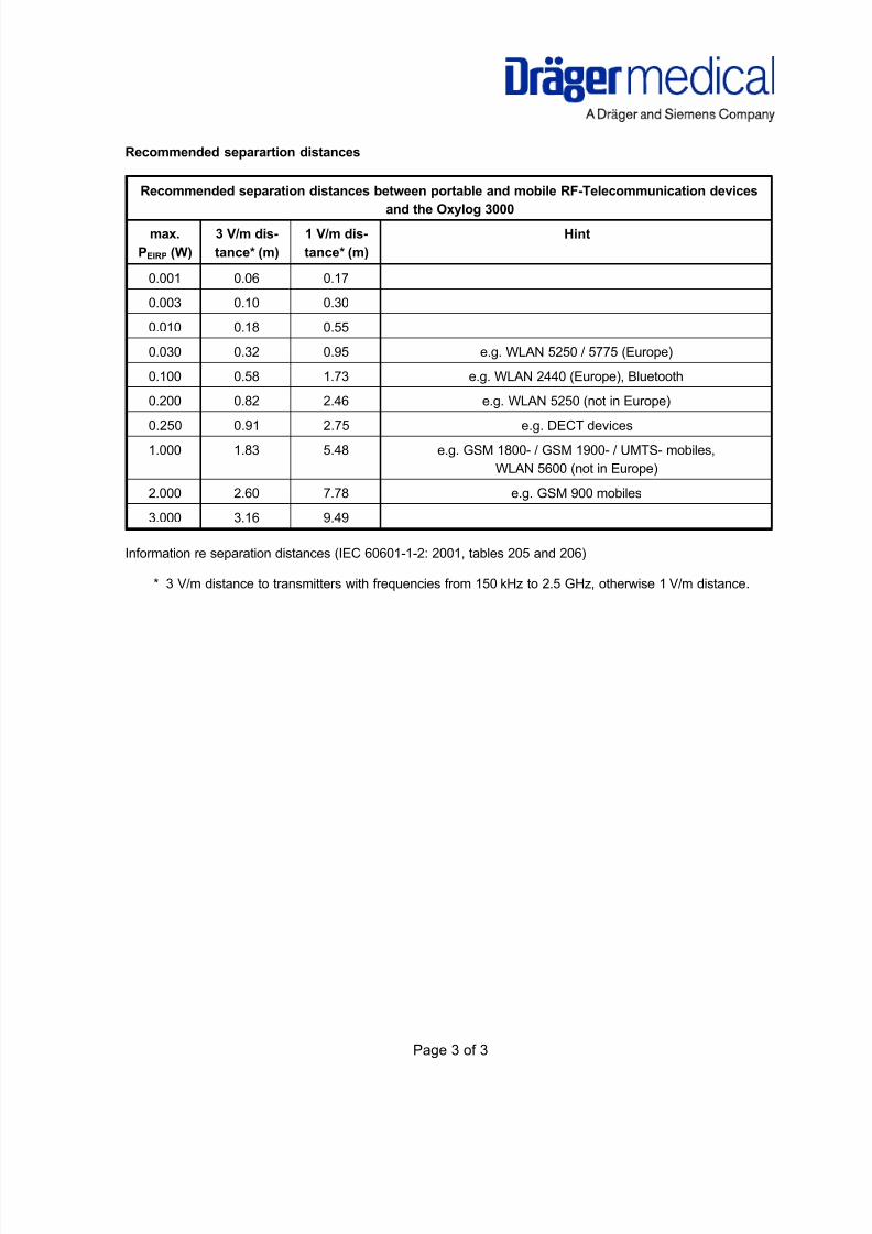
Recommended separartion distances
Recommended separation distances between portable and mobile RF-Telecommunication devicesand the Oxylog 3000
max.
PEIRP (W)
3 V/m dis-
tance* (m)
1 V/m dis-
tance* (m)
Hint
0.001 0.06 0.17
0.003 0.10 0.30
0.010 0.18 0.55
0.030 0.32 0.95 e.g. WLAN 5250 / 5775 (Europe)
0.100 0.58 1.73 e.g. WLAN 2440 (Europe), Bluetooth
0.200 0.82 2.46 e.g. WLAN 5250 (not in Europe)
0.250 0.91 2.75 e.g. DECT devices
1.000 1.83 5.48 e.g. GSM 1800- / GSM 1900- / UMTS- mobiles,
WLAN 5600 (not in Europe)
2.000 2.60 7.78 e.g. GSM 900 mobiles
3.000 3.16 9.49
Information re separation distances (IEC 60601-1-2: 2001, tables 205 and 206)
* 3 V/m distance to transmitters with frequencies from 150 kHz to 2.5 GHz, otherwise 1 V/m distance.

8/10/2019 Dräger Oxylog 3000 - Service Manuals
http://slidepdf.com/reader/full/draeger-oxylog-3000-service-manuals 68/69
8/10/2019 Dräger Oxylog 3000 - Service Manuals
http://slidepdf.com/reader/full/draeger-oxylog-3000-service-manuals 69/69
Manufacturer: Support:
Dräger Medical b.v. Dräger Medical AG & Co. KG
Kanaaldijk 29 Moislinger Allee 53 – 55
NL-5683 CR BEST D-23542 Lübeck
The Netherlands Germany
Phone: (+31) 499 331 - 331 Phone: (+49) (0) 1805-3723437
Fax: (+31) 499 331 - 335 Fax: (+49) 451/882 - 3779
Subject to change without notice
Will not be replaced in the event of modifications.