Embed Size (px)
Citation preview
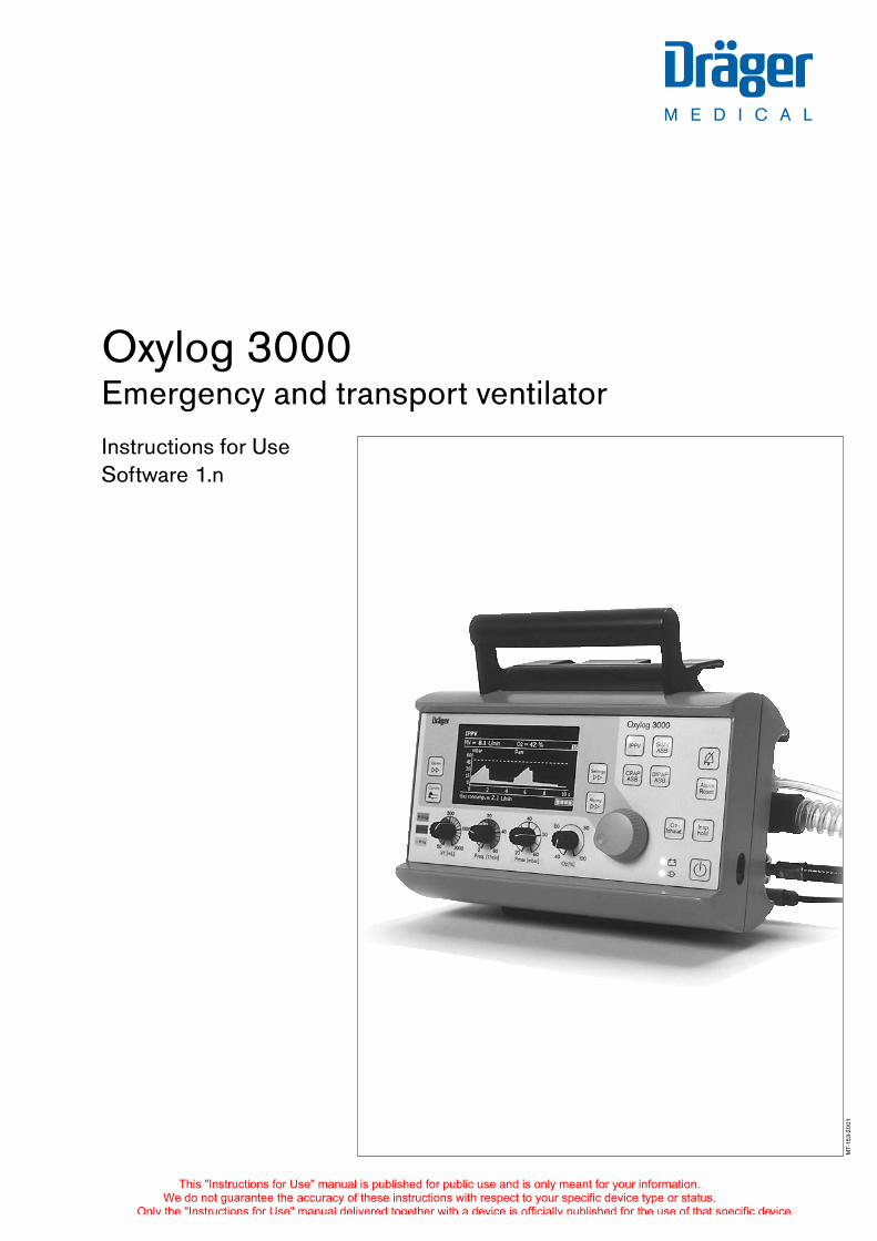
M E D I C A L
D
Instructions for UseSoftware 1.n
Oxylog 3000Emergency and transport ventilator
MT-
153-
2001
This "Instructions for Use" manual is published for public use and is only meant for your information.We do not guarantee the accuracy of these instructions with respect to your specific device type or status.
Only the "Instructions for Use" manual delivered together with a device is officially published for the use of that specific device.
2
How to use these Instructions for Use
The header line ...specifies the subject of the main chapter.
It is followed by the title of the sub-chapter – to help you find your way rapidly around the manual.
The page body ...contains the instructions for use
in a combination of text and illustrations. The information is expressed directly in terms of actions which enable users to familiarise themselves with the operation of the machine by hands-on activity.
The left-hand column ...contains the text
which provides explanations and guides the user with brief and clear instructions in an ergonomic sequence for confusion free use of the machine.Bullet points indicate the working steps, numbers are used to highlight the relation between the working step described, the associated illustration(s) and the sequence of operations.
The right-hand column ... contains the illustration(s)
which directly relate to the text opposite and show the user where to find the items concerned. The focus is on the elements mentioned in the text. Non-essentials are omitted.Screen dumps are also used to guide the user and confirm the working steps.
Preparation
20
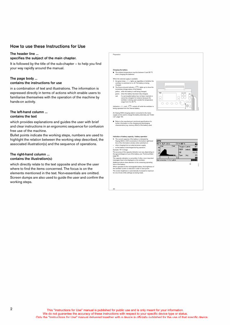
Charging the battery
! The ambient temperature must be between 0 and 35 oC when charging the batteries!
When the external supply is available:1 the green lamp » N «, lights up regardless of whether the
ventilator is switched on or off. The battery is being charged.
2 The three-coloured indicator » J « lights up to show the momentary charge status of the battery:yellow: while the battery is still being charged,green: when the battery has been fully charged,red: if a serviceable battery has not been inserted or
cannot be charged, for instance because the ventilator is being used outside the temperaturerange from 0 to 35 oC.
Indicators » N « and » J « remain off while the ventilator is being operated from the internal battery.
An Oxylog 3000 charging station connected to the mains supply can be used to charge the battery externally, see "Order List", page 102.
! Refer to the manufacturer's technical specifications for further information on the charging and discharging characteristics (e.g. memory effect) of the battery used.
Indication of battery capacity / battery operation
3 The current capacity of the battery is indicated by Oxylog 3000 in 25% increments in the bottom right-hand line of the information window when switched on:
— when charging from an external power supply,— as the battery is discharged during operation.Example: 75 % chargeThe accuracy of the capacity indication can vary, depending on the age and degree of use of the battery, see "Technical Data", page 90.The capacity indication is overwritten if other, more important messages have to be displayed on the ventilator.Additional alarms draw attention to the remaining operating time of the battery. When operated via the rechargeable battery, the brightness of the ventilator screen is reduced in order to save power.The screen brightness is automatically increased to maximum for one minute while settings are being made.
0243
7170
Oxylog 3000
1
2
0573
7171"
This "Instructions for Use" manual is published for public use and is only meant for your information.We do not guarantee the accuracy of these instructions with respect to your specific device type or status.
Only the "Instructions for Use" manual delivered together with a device is officially published for the use of that specific device.
3
Contents
For Your Safety and that of Your Patients 5
Intended Medical Use 7
Operating concept 9
Preparation 15
Checking readiness for operation 25
Operation 31
Fault – Cause – Remedy 53
Care 57
What's what 65
Accessories 71
Service Mode 75
Abbreviations and symbols 83
Technical Data 87
Description 95
Order List 102
Index 104
This "Instructions for Use" manual is published for public use and is only meant for your information.We do not guarantee the accuracy of these instructions with respect to your specific device type or status.
Only the "Instructions for Use" manual delivered together with a device is officially published for the use of that specific device.

4
This "Instructions for Use" manual is published for public use and is only meant for your information.We do not guarantee the accuracy of these instructions with respect to your specific device type or status.
Only the "Instructions for Use" manual delivered together with a device is officially published for the use of that specific device.

For Your Safety and that of Your Patients
5
For Your Safety and that of Your Patients . . . . . . . . . . . . . . . . . . . . . . . . . . . . . . . . 6
Precautions . . . . . . . . . . . . . . . . . . . . . . . . . . . . . . . . . . . . . . . . . . . . . . . . . . . . . . . . . . . . 6
For Your Safety and that of Your Patients
This "Instructions for Use" manual is published for public use and is only meant for your information.We do not guarantee the accuracy of these instructions with respect to your specific device type or status.
Only the "Instructions for Use" manual delivered together with a device is officially published for the use of that specific device.
6
For Your Safety and that of Your Patients
For Your Safety and that of Your Patients
Strictly follow the Instructions for Use
Any use of the apparatus requires full understanding and strict observation of these instructions.The apparatus is only to be used for purposes specified here.
Maintenance
The apparatus must be inspected and serviced by trained service personnel every two years.Repair and general overhaul of the apparatus may only be carried out by trained service personnel.We recommend that a service contract be obtained with DrägerService and that all repairs also be carried out by them.Only authentic Dräger spare parts may be used for maintenance.Observe chapter "Maintenance Intervals".
Accessories
Do not use accessory parts other than those in the order list. Liability for proper function or damage
The liability for the proper function of the apparatus is irrevocably transferred to the owner or operator to the extent that the apparatus is serviced or repaired by personnel not employed or authorized by DrägerService or if the apparatus is used in a manner not conforming to its intended use.Dräger cannot be held responsible for damage caused by non-compliance with the recommendations given above. The warranty and liability provisions of the terms of sale and delivery of Dräger are likewise not modified by the recommendations given above. Dräger Medical AG & Co. KGaA
Precautions
Ventilation must be monitoredThis equipment must only be used under the supervision of qualified medical staff, so that if any faults or mal-functions occur, help is available immediately!
This equipment must not be used with flammable gases or anaesthetic agents. Danger of fire!
Mobile phones must not be used within a radius of 10 metres of the apparatus.Mobile phones can interfere with the operation of electrical medical apparatus and endanger the patient!*
* Dräger medical equipment fulfils the interference resistance requirements according to the product-specific standards or EN 60601-1-2 (IEC 601-1-2). However, depending on the design of the mobile phone and circumstances of use, field strengths may occur in the immediate environment of a mobile phone that exceed the limits of the above standards and therefore cause interference.
Do not use the equipment in conjunction with magnetic resonance imaging (MRI, NMR, NMI)!The apparatus may malfunction, causing danger to the patient.
Do not use the equipment in hyperbaric chambers!The apparatus may malfunction, causing danger to the patient.
Avoid pollutants in the ambient air!Oxylog 3000 uses ambient air for ventilation when the O2 concentration is less than 100 vol.%. Pollutants would enter the patient’s body.
Manual ventilation equipment must be kept ready to hand
If the life-supporting function of the ventilator can no longer be guaranteed on account of a fault, such as a power failure or break in the medical gas supply, ventilation of the patient must be continued without delay using other ventilation equipment, such as a manual ventilation bag Resutator 2000, with PEEP and/or increased inspiratory O2 concentration if necessary. See Order List on page 102.
Not for use in areas of explosion hazard
This apparatus is neither approved nor certified for use in areas where combustible or explosive gas mixtures are likely to occur.
This "Instructions for Use" manual is published for public use and is only meant for your information.We do not guarantee the accuracy of these instructions with respect to your specific device type or status.
Only the "Instructions for Use" manual delivered together with a device is officially published for the use of that specific device.

Intended Medical Use
7
Intended Medical Use . . . . . . . . . . . . . . . . . . . . . . . . . . . . . . . . . . . . . . . . . . . . . . . . . . . 8
Intended Medical Use
This "Instructions for Use" manual is published for public use and is only meant for your information.We do not guarantee the accuracy of these instructions with respect to your specific device type or status.
Only the "Instructions for Use" manual delivered together with a device is officially published for the use of that specific device.
8
Intended Medical Use
Intended Medical Use
Oxylog® 3000 is a time-cycled, volume-constant and pressure-controlled emergency and transport ventilator for patients with a tidal volume from 50 mL upwards.
With the following ventilation modes
— IPPV/IPPVAssist (CMV/CMVAssist*)Intermittent Positive Pressure VentilationControlled and assisted volume-constant ventilation with PEEP for CPPV.
— SIMV/ASB (SIMV/PS)Synchronized Intermittent Mandatory VentilationProcedure for weaning patients off the ventilator after they have started spontaneous breathing, with adjustable pressure assist during spontaneous breathing.
— CPAP/ASB (SIMV/PS)Continuous Positive Airway PressureSpontaneous breathing with positive airway pressure and adjustable pressure assist.
— BIPAP/ASB** (PCV+/PS*)Biphasic Positive Airway PressurePressure-controlled ventilation combined with free spontaneous breathing during the complete breathing cycle, and adjustable pressure assist on CPAP level.
The settings PCV+, PS and CMV can be viewed in the US-English display, see "Customer Service Mode", "Display language text", page 81.
Special modes
— Apnoea VentilationFor switching over automatically to volume-controlled mandatory ventilation, if breathing stops.
— NIVNon-invasive ventilation for mask ventilation with leakage compensation.
For O2 inhalation
– with inhalation mask
With monitoring
— Airway pressure Paw— Expiratory minute volume MV— Apnoea— Rapid shallow breathing: High frequency alarm
* CMV Controlled Mandatory VentilationPCV+ Pressure Controlled Ventilation plusPS Pressure Support
** Licensed trademark
Areas of use
Mobile use for emergency medical care or primary care of emergency patients:— During transport in emergency rescue vehicles or by
helicopter,— In accident and emergency departments, in the recovery
room.
Mobile use for secondary transfers:— During transfer by road or air— When moving ventilated patients around the hospital.
These Instructions for Use describe the maximum equipment configuration for Oxylog 3000.Depending on the actual configuration used, the maximum equipment may not include the following options:— O2 blending— BIPAP (PCV+)— ASB (PS)— O2 inhalation— 100 % O2
This "Instructions for Use" manual is published for public use and is only meant for your information.We do not guarantee the accuracy of these instructions with respect to your specific device type or status.
Only the "Instructions for Use" manual delivered together with a device is officially published for the use of that specific device.
Operating concept
9
Operating concept . . . . . . . . . . . . . . . . . . . . . . . . . . . . . . . . . . . . . . . . . . . . . . . . . . . . 10
Key for switching on/off . . . . . . . . . . . . . . . . . . . . . . . . . . . . . . . . . . . . . . . . . . . . . . 10
Ventilation Controls . . . . . . . . . . . . . . . . . . . . . . . . . . . . . . . . . . . . . . . . . . . . . . . . . 10
Selecting the ventilation mode . . . . . . . . . . . . . . . . . . . . . . . . . . . . . . . . . . . . . . . . 11
Keys for routine and additional functions . . . . . . . . . . . . . . . . . . . . . . . . . . . . . . . 11
Screen Operating Controls . . . . . . . . . . . . . . . . . . . . . . . . . . . . . . . . . . . . . . . . . . . 11
Structure of the screen windows . . . . . . . . . . . . . . . . . . . . . . . . . . . . . . . . . . . . . . 12
"Values" screen window . . . . . . . . . . . . . . . . . . . . . . . . . . . . . . . . . . . . . . . . . . . . . . 12
"Settings" screen window . . . . . . . . . . . . . . . . . . . . . . . . . . . . . . . . . . . . . . . . . . . . 12
"Alarms" screen window . . . . . . . . . . . . . . . . . . . . . . . . . . . . . . . . . . . . . . . . . . . . . 13
Pressure curves main page . . . . . . . . . . . . . . . . . . . . . . . . . . . . . . . . . . . . . . . . . . . 13
Flow curves main page . . . . . . . . . . . . . . . . . . . . . . . . . . . . . . . . . . . . . . . . . . . . . . 13
Information window on screen . . . . . . . . . . . . . . . . . . . . . . . . . . . . . . . . . . . . . . . . 14
Operating concept
This "Instructions for Use" manual is published for public use and is only meant for your information.We do not guarantee the accuracy of these instructions with respect to your specific device type or status.
Only the "Instructions for Use" manual delivered together with a device is officially published for the use of that specific device.
Operating concept
10
Operating concept
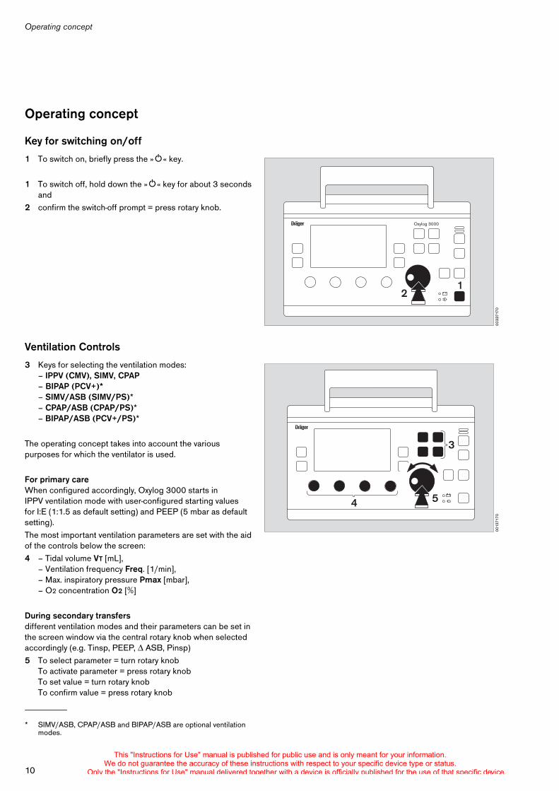
Key for switching on/off
1 To switch on, briefly press the »O« key.
1 To switch off, hold down the »O« key for about 3 secondsand
2 confirm the switch-off prompt = press rotary knob.
Ventilation Controls
3 Keys for selecting the ventilation modes:– IPPV (CMV), SIMV, CPAP– BIPAP (PCV+)*– SIMV/ASB (SIMV/PS)* – CPAP/ASB (CPAP/PS)*– BIPAP/ASB (PCV+/PS)*
The operating concept takes into account the various purposes for which the ventilator is used.
For primary careWhen configured accordingly, Oxylog 3000 starts in IPPV ventilation mode with user-configured starting values for I:E (1:1.5 as default setting) and PEEP (5 mbar as default setting).The most important ventilation parameters are set with the aid of the controls below the screen:4 – Tidal volume VT [mL],
– Ventilation frequency Freq. [1/min],– Max. inspiratory pressure Pmax [mbar],– O2 concentration O2 [%]
During secondary transfersdifferent ventilation modes and their parameters can be set in the screen window via the central rotary knob when selected accordingly (e.g. Tinsp, PEEP, ASB, Pinsp)5 To select parameter = turn rotary knob
To activate parameter = press rotary knobTo set value = turn rotary knobTo confirm value = press rotary knob
* SIMV/ASB, CPAP/ASB and BIPAP/ASB are optional ventilation modes.
0033
7170
Oxylog 3000
21
0013
7170
3
54
This "Instructions for Use" manual is published for public use and is only meant for your information.We do not guarantee the accuracy of these instructions with respect to your specific device type or status.
Only the "Instructions for Use" manual delivered together with a device is officially published for the use of that specific device.
11
Operating concept
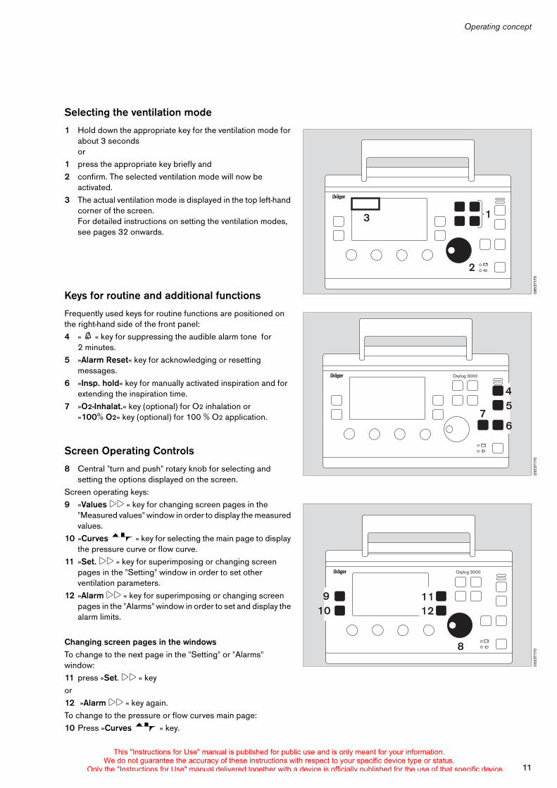
Selecting the ventilation mode
1 Hold down the appropriate key for the ventilation mode for about 3 secondsor
1 press the appropriate key briefly and2 confirm. The selected ventilation mode will now be
activated.3 The actual ventilation mode is displayed in the top left-hand
corner of the screen.For detailed instructions on setting the ventilation modes, see pages 32 onwards.
Keys for routine and additional functions
Frequently used keys for routine functions are positioned on the right-hand side of the front panel:4 » g « key for suppressing the audible alarm tone for
2 minutes.5 »Alarm Reset« key for acknowledging or resetting
messages.6 »Insp. hold« key for manually activated inspiration and for
extending the inspiration time.7 »O2-Inhalat.« key (optional) for O2 inhalation or
»100% O2« key (optional) for 100 % O2 application.
Screen Operating Controls
8 Central "turn and push" rotary knob for selecting and setting the options displayed on the screen.
Screen operating keys:9 »Values !! « key for changing screen pages in the
"Measured values" window in order to display the measured values.
10 »Curves « key for selecting the main page to display the pressure curve or flow curve.
11 »Set. !! « key for superimposing or changing screen pages in the "Setting" window in order to set other ventilation parameters.
12 »Alarm !! « key for superimposing or changing screen pages in the "Alarms" window in order to set and display the alarm limits.
Changing screen pages in the windowsTo change to the next page in the "Setting" or "Alarms" window:11 press »Set. !! « keyor 12 »Alarm !! « key again.To change to the pressure or flow curves main page:10 Press »Curves « key.
0853
7170
1
2
3
0323
7170
Oxylog 3000
45
76
0023
7170
Oxylog 3000
8
9 1110 12
This "Instructions for Use" manual is published for public use and is only meant for your information.We do not guarantee the accuracy of these instructions with respect to your specific device type or status.
Only the "Instructions for Use" manual delivered together with a device is officially published for the use of that specific device.
Operating concept
12
Structure of the screen windows
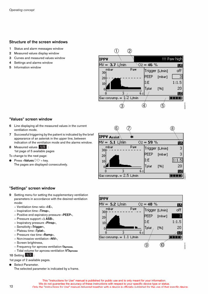
1 Status and alarm messages window2 Measured values display window3 Curves and measured values window4 Settings and alarms window5 Information window
"Values" screen window
6 Line displaying all the measured values in the current ventilation mode.
7 Successful triggering by the patient is indicated by the brief appearance of an asterisk in the upper line, between indication of the ventilation mode and the alarms window.
8 Measured values : 1st page of 5 available pages
To change to the next page:! Press »Values !! « key.
The pages are displayed consecutively.
"Settings" screen window
9 Setting menu for setting the supplementary ventilation parameters in accordance with the desired ventilation mode:– Ventilation time ratio »I:E«, – Inspiration time »Tinsp«,– Positive end expiratory pressure »PEEP«,– Pressure support » ASB«,– Inspiratory pressure »Pinsp«,– Sensitivity »Trigger«,– Plateau time »Tplat«,– Pressure rise time »Ramp«,– Non-invasive ventilation »NIV«,– Screen brightness,– Frequency for apnoea ventilation fApnoea,
– Tidal volume for apnoea ventilation VTApnoea
10 Setting : 1st page of 2 available pages.! Select Parameter.
The selected parameter is indicated by a frame.
0543
7171
#$
% &"
0583
7171
' ( )
1/5
0573
7171* +
1/2
This "Instructions for Use" manual is published for public use and is only meant for your information.We do not guarantee the accuracy of these instructions with respect to your specific device type or status.
Only the "Instructions for Use" manual delivered together with a device is officially published for the use of that specific device.
13
Operating concept
! Activate parameter for setting.The active parameter appears light on a dark background.
! Set parameter and confirm. To change to the next page:! Press »Set. !! « key.
The pages are displayed consecutively.
"Alarms" screen window
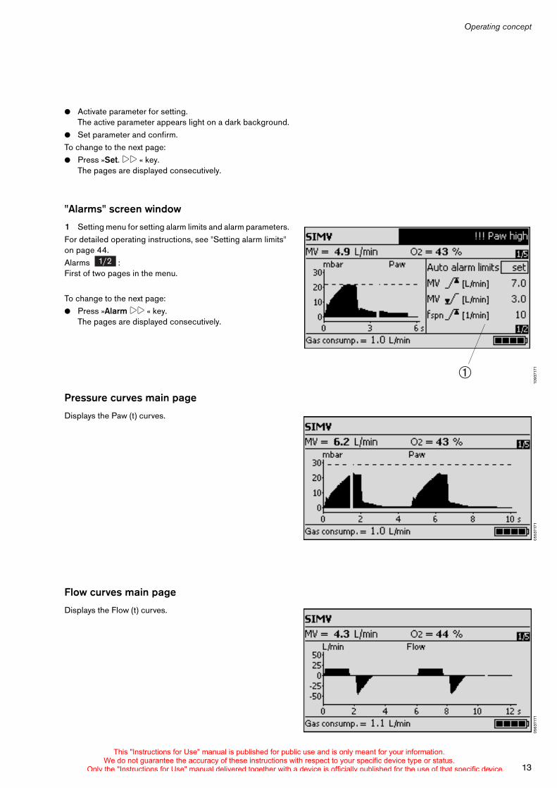
1 Setting menu for setting alarm limits and alarm parameters. For detailed operating instructions, see "Setting alarm limits" on page 44.Alarms :First of two pages in the menu.
To change to the next page:! Press »Alarm !! « key.
The pages are displayed consecutively.
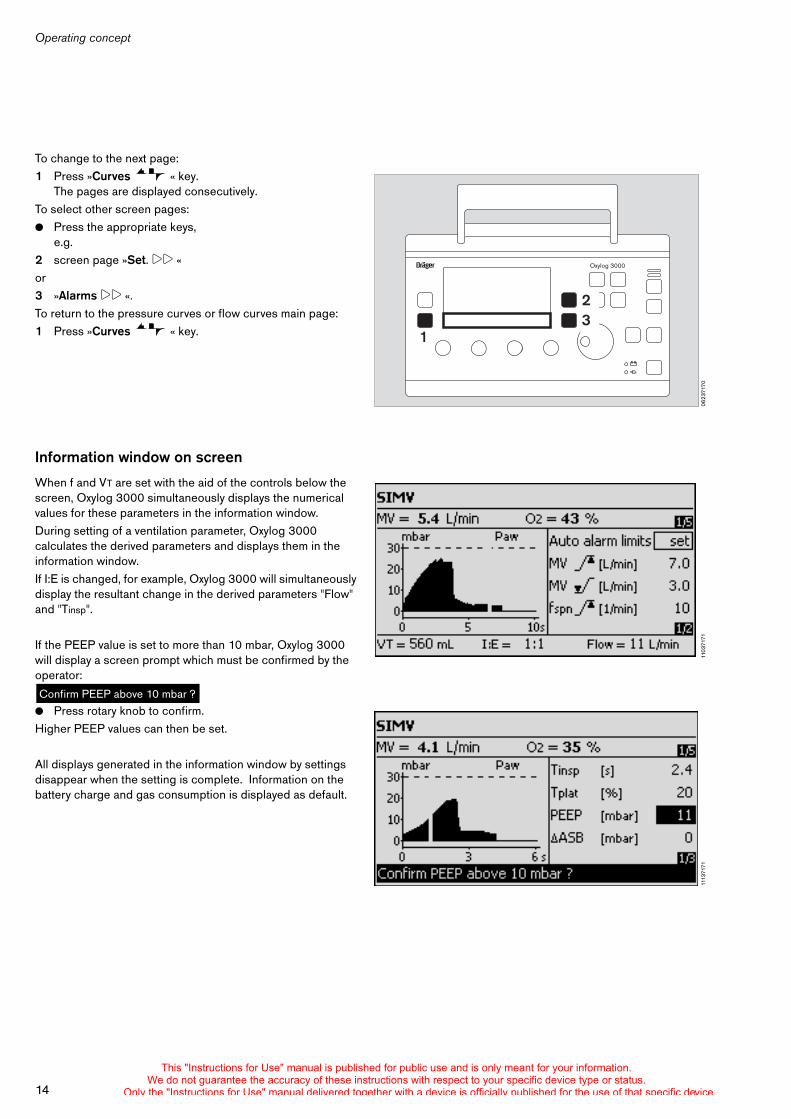
Pressure curves main page
Displays the Paw (t) curves.
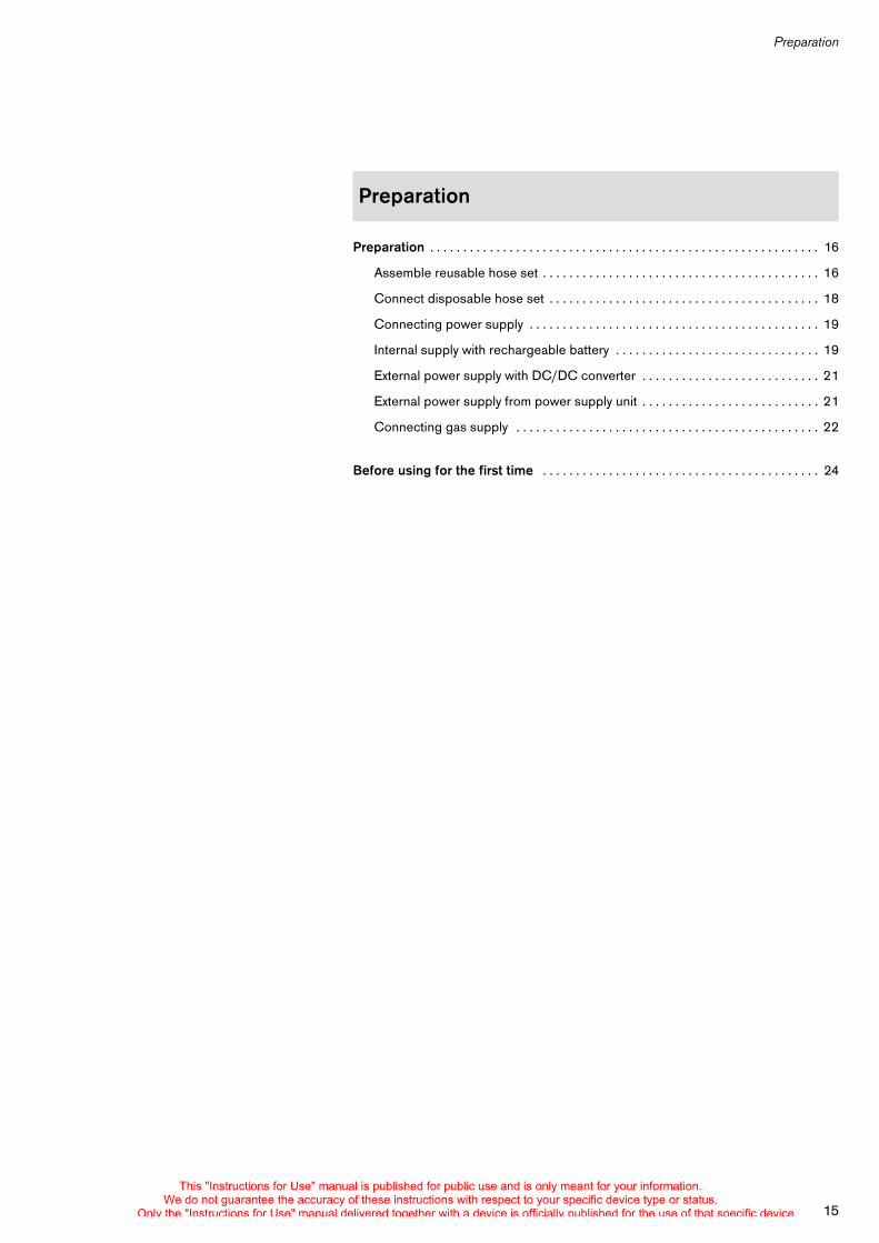
Flow curves main page
Displays the Flow (t) curves.
1093
7171$
1/2
0553
7171
0563
7171
This "Instructions for Use" manual is published for public use and is only meant for your information.We do not guarantee the accuracy of these instructions with respect to your specific device type or status.
Only the "Instructions for Use" manual delivered together with a device is officially published for the use of that specific device.
Operating concept
14
To change to the next page:1 Press »Curves « key.
The pages are displayed consecutively.To select other screen pages:! Press the appropriate keys,
e.g. 2 screen page »Set. !! « or 3 »Alarms !! «.To return to the pressure curves or flow curves main page:1 Press »Curves « key.
Information window on screen
When f and VT are set with the aid of the controls below the screen, Oxylog 3000 simultaneously displays the numerical values for these parameters in the information window.During setting of a ventilation parameter, Oxylog 3000 calculates the derived parameters and displays them in the information window.If I:E is changed, for example, Oxylog 3000 will simultaneously display the resultant change in the derived parameters "Flow" and "Tinsp".
If the PEEP value is set to more than 10 mbar, Oxylog 3000 will display a screen prompt which must be confirmed by the operator:
! Press rotary knob to confirm. Higher PEEP values can then be set.
All displays generated in the information window by settings disappear when the setting is complete. Information on the battery charge and gas consumption is displayed as default.
0623
7170
Oxylog 3000
1
23
1103
7171
Confirm PEEP above 10 mbar ?11
1371
71
This "Instructions for Use" manual is published for public use and is only meant for your information.We do not guarantee the accuracy of these instructions with respect to your specific device type or status.
Only the "Instructions for Use" manual delivered together with a device is officially published for the use of that specific device.
Preparation
15
Preparation . . . . . . . . . . . . . . . . . . . . . . . . . . . . . . . . . . . . . . . . . . . . . . . . . . . . . . . . . . . 16
Assemble reusable hose set . . . . . . . . . . . . . . . . . . . . . . . . . . . . . . . . . . . . . . . . . . 16
Connect disposable hose set . . . . . . . . . . . . . . . . . . . . . . . . . . . . . . . . . . . . . . . . . 18
Connecting power supply . . . . . . . . . . . . . . . . . . . . . . . . . . . . . . . . . . . . . . . . . . . . 19
Internal supply with rechargeable battery . . . . . . . . . . . . . . . . . . . . . . . . . . . . . . . 19
External power supply with DC/DC converter . . . . . . . . . . . . . . . . . . . . . . . . . . . 21
External power supply from power supply unit . . . . . . . . . . . . . . . . . . . . . . . . . . . 21
Connecting gas supply . . . . . . . . . . . . . . . . . . . . . . . . . . . . . . . . . . . . . . . . . . . . . . 22
Before using for the first time . . . . . . . . . . . . . . . . . . . . . . . . . . . . . . . . . . . . . . . . . . 24
Preparation
This "Instructions for Use" manual is published for public use and is only meant for your information.We do not guarantee the accuracy of these instructions with respect to your specific device type or status.
Only the "Instructions for Use" manual delivered together with a device is officially published for the use of that specific device.
Preparation
16
Preparation
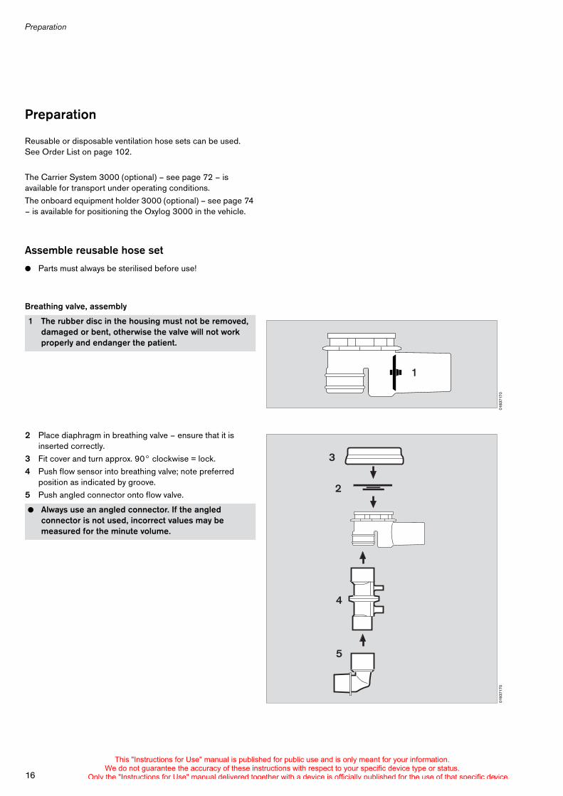
Reusable or disposable ventilation hose sets can be used. See Order List on page 102.
The Carrier System 3000 (optional) – see page 72 – is available for transport under operating conditions.The onboard equipment holder 3000 (optional) – see page 74 – is available for positioning the Oxylog 3000 in the vehicle.
Assemble reusable hose set
! Parts must always be sterilised before use!
Breathing valve, assembly
2 Place diaphragm in breathing valve – ensure that it is inserted correctly.
3 Fit cover and turn approx. 90° clockwise = lock.4 Push flow sensor into breathing valve; note preferred
position as indicated by groove.5 Push angled connector onto flow valve.
1 The rubber disc in the housing must not be removed, damaged or bent, otherwise the valve will not work properly and endanger the patient.
! Always use an angled connector. If the angled connector is not used, incorrect values may be measured for the minute volume.
0183
7170
1
0193
7170
3
2
4
5
This "Instructions for Use" manual is published for public use and is only meant for your information.We do not guarantee the accuracy of these instructions with respect to your specific device type or status.
Only the "Instructions for Use" manual delivered together with a device is officially published for the use of that specific device.
17
Preparation
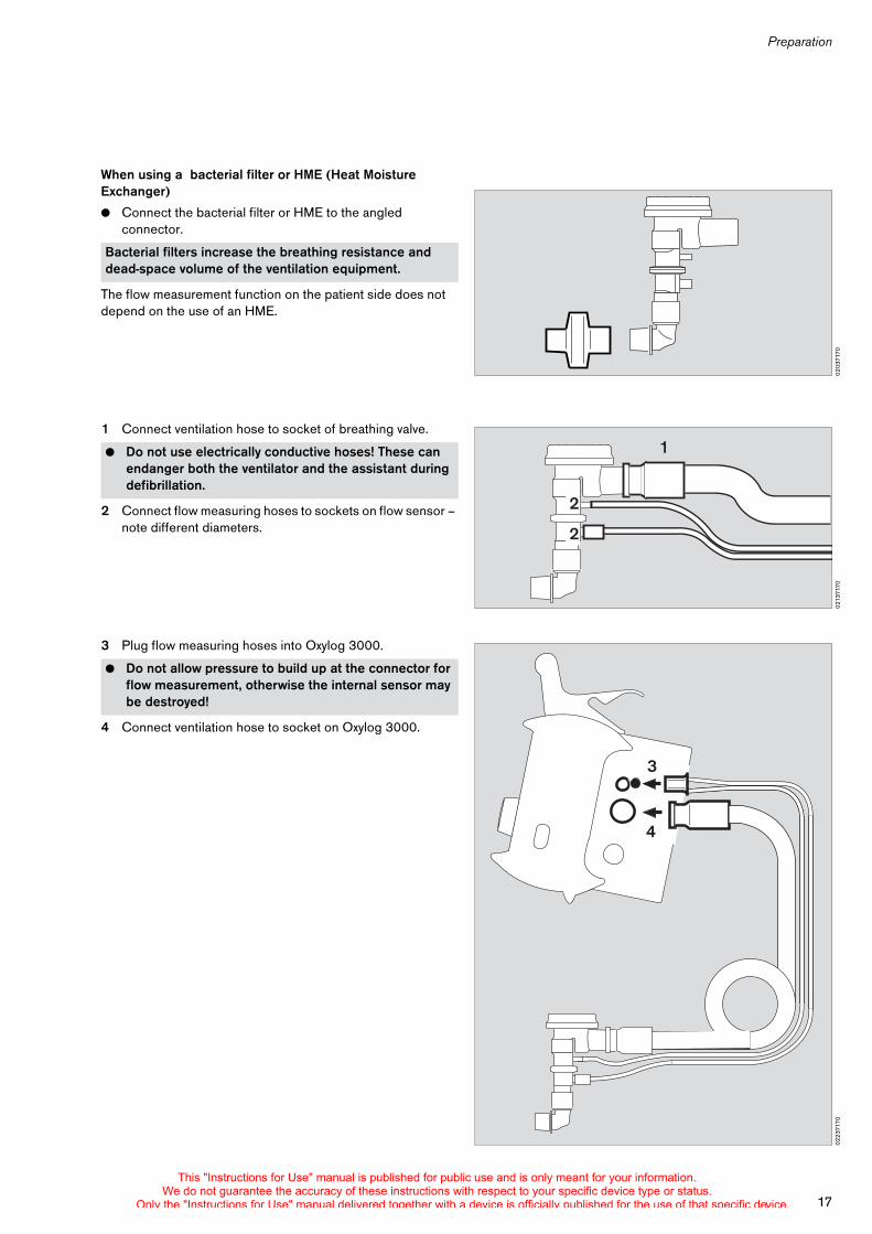
When using a bacterial filter or HME (Heat Moisture Exchanger)
! Connect the bacterial filter or HME to the angled connector.
The flow measurement function on the patient side does not depend on the use of an HME.
1 Connect ventilation hose to socket of breathing valve.
2 Connect flow measuring hoses to sockets on flow sensor – note different diameters.
3 Plug flow measuring hoses into Oxylog 3000.
4 Connect ventilation hose to socket on Oxylog 3000.
Bacterial filters increase the breathing resistance and dead-space volume of the ventilation equipment.
! Do not use electrically conductive hoses! These can endanger both the ventilator and the assistant during defibrillation.
! Do not allow pressure to build up at the connector for flow measurement, otherwise the internal sensor may be destroyed!
0203
7170
0213
7170
1
2
2
0223
7170
4
3
This "Instructions for Use" manual is published for public use and is only meant for your information.We do not guarantee the accuracy of these instructions with respect to your specific device type or status.
Only the "Instructions for Use" manual delivered together with a device is officially published for the use of that specific device.
Preparation
18
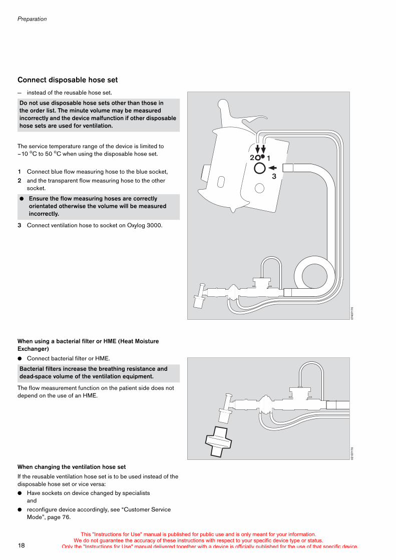
Connect disposable hose set
— instead of the reusable hose set.
The service temperature range of the device is limited to –10 oC to 50 oC when using the disposable hose set.
1 Connect blue flow measuring hose to the blue socket,2 and the transparent flow measuring hose to the other
socket.
3 Connect ventilation hose to socket on Oxylog 3000.
When using a bacterial filter or HME (Heat Moisture Exchanger)
! Connect bacterial filter or HME.
The flow measurement function on the patient side does not depend on the use of an HME.
When changing the ventilation hose set
If the reusable ventilation hose set is to be used instead of the disposable hose set or vice versa:! Have sockets on device changed by specialists
and! reconfigure device accordingly, see “Customer Service
Mode”, page 76.
Do not use disposable hose sets other than those in the order list. The minute volume may be measured incorrectly and the device malfunction if other disposable hose sets are used for ventilation.
! Ensure the flow measuring hoses are correctly orientated otherwise the volume will be measured incorrectly.
Bacterial filters increase the breathing resistance and dead-space volume of the ventilation equipment.
0743
7170
2 1
3
0213
7170
This "Instructions for Use" manual is published for public use and is only meant for your information.We do not guarantee the accuracy of these instructions with respect to your specific device type or status.
Only the "Instructions for Use" manual delivered together with a device is officially published for the use of that specific device.
19
Preparation
Connecting power supply
Oxylog 3000 is designed to operate on power supplies with different voltages:
Internal supply
— with rechargeable battery (specified Smart Battery, see "Technical Data", page 88)
Additional external power supply
To recharge the battery and to extend the electrical operation time when using a rechargeable battery.— DC voltage from the on-board power supply via
DC/DC converteror
— with AC/DC power pack.
! Have a fully charged battery on hand, page 20.The device can only ventilate the patient continuously even when the external power supply is interrupted if fully charged batteries are always available.
Internal supply with rechargeable battery
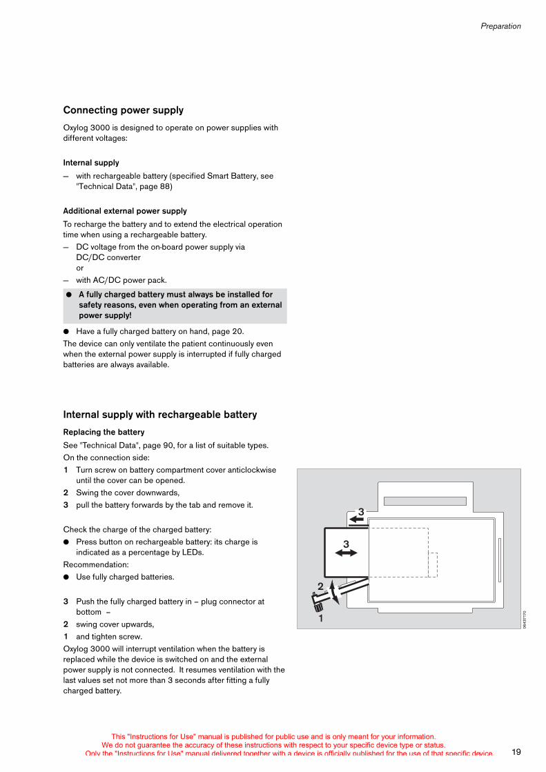
Replacing the battery
See "Technical Data", page 90, for a list of suitable types.On the connection side:1 Turn screw on battery compartment cover anticlockwise
until the cover can be opened.2 Swing the cover downwards,3 pull the battery forwards by the tab and remove it.
Check the charge of the charged battery:! Press button on rechargeable battery: its charge is
indicated as a percentage by LEDs.Recommendation:! Use fully charged batteries.
3 Push the fully charged battery in – plug connector at bottom –
2 swing cover upwards,1 and tighten screw.Oxylog 3000 will interrupt ventilation when the battery is replaced while the device is switched on and the external power supply is not connected. It resumes ventilation with the last values set not more than 3 seconds after fitting a fully charged battery.
! A fully charged battery must always be installed for safety reasons, even when operating from an external power supply!
0643
7170
3
3
2
1
This "Instructions for Use" manual is published for public use and is only meant for your information.We do not guarantee the accuracy of these instructions with respect to your specific device type or status.
Only the "Instructions for Use" manual delivered together with a device is officially published for the use of that specific device.
Preparation
20
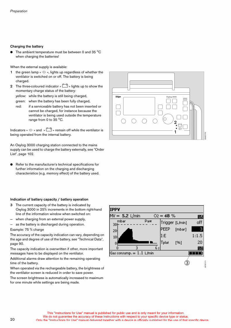
Charging the battery
! The ambient temperature must be between 0 and 35 oC when charging the batteries!
When the external supply is available:1 the green lamp » N «, lights up regardless of whether the
ventilator is switched on or off. The battery is being charged.
2 The three-coloured indicator » J « lights up to show the momentary charge status of the battery:yellow: while the battery is still being charged,green: when the battery has been fully charged,red: if a serviceable battery has not been inserted or
cannot be charged, for instance because the ventilator is being used outside the temperaturerange from 0 to 35 oC.
Indicators » N « and » J « remain off while the ventilator is being operated from the internal battery.
An Oxylog 3000 charging station connected to the mains supply can be used to charge the battery externally, see "Order List", page 102.
! Refer to the manufacturer's technical specifications for further information on the charging and discharging characteristics (e.g. memory effect) of the battery used.
Indication of battery capacity / battery operation
3 The current capacity of the battery is indicated by Oxylog 3000 in 25% increments in the bottom right-hand line of the information window when switched on:
— when charging from an external power supply,— as the battery is discharged during operation.Example: 75 % chargeThe accuracy of the capacity indication can vary, depending on the age and degree of use of the battery, see "Technical Data", page 90.The capacity indication is overwritten if other, more important messages have to be displayed on the ventilator.Additional alarms draw attention to the remaining operating time of the battery. When operated via the rechargeable battery, the brightness of the ventilator screen is reduced in order to save power.The screen brightness is automatically increased to maximum for one minute while settings are being made.
0243
7170
Oxylog 3000
1
2
0573
7171"
This "Instructions for Use" manual is published for public use and is only meant for your information.We do not guarantee the accuracy of these instructions with respect to your specific device type or status.
Only the "Instructions for Use" manual delivered together with a device is officially published for the use of that specific device.
21
Preparation
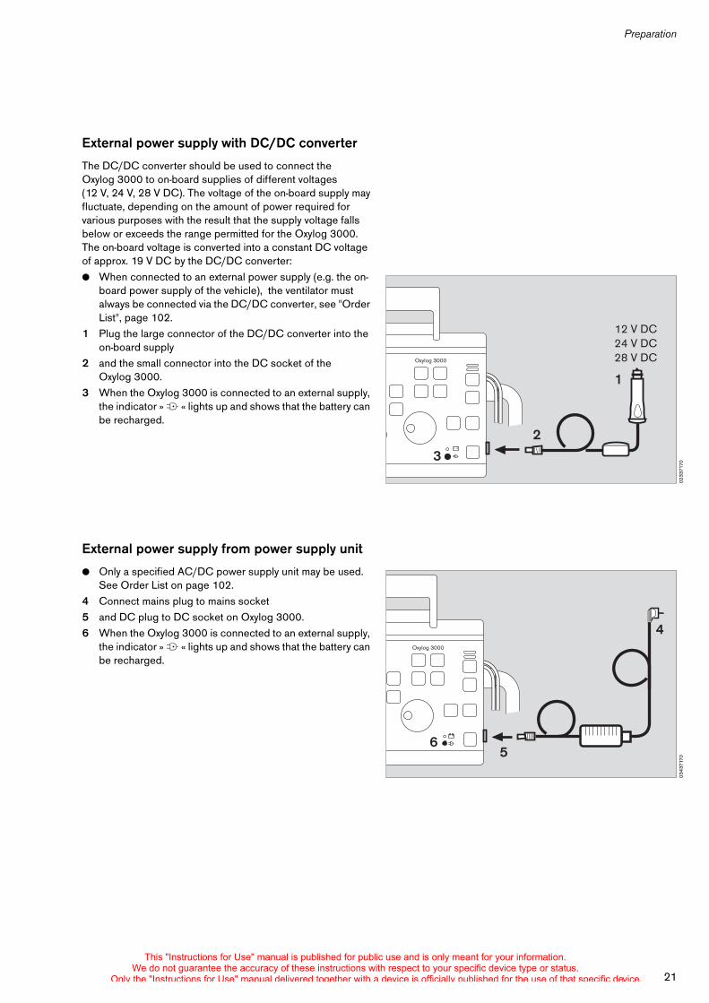
External power supply with DC/DC converter
The DC/DC converter should be used to connect the Oxylog 3000 to on-board supplies of different voltages (12 V, 24 V, 28 V DC). The voltage of the on-board supply may fluctuate, depending on the amount of power required for various purposes with the result that the supply voltage falls below or exceeds the range permitted for the Oxylog 3000. The on-board voltage is converted into a constant DC voltage of approx. 19 V DC by the DC/DC converter:! When connected to an external power supply (e.g. the on-
board power supply of the vehicle), the ventilator must always be connected via the DC/DC converter, see "Order List", page 102.
1 Plug the large connector of the DC/DC converter into the on-board supply
2 and the small connector into the DC socket of the Oxylog 3000.
3 When the Oxylog 3000 is connected to an external supply, the indicator » N « lights up and shows that the battery can be recharged.
External power supply from power supply unit
! Only a specified AC/DC power supply unit may be used. See Order List on page 102.
4 Connect mains plug to mains socket 5 and DC plug to DC socket on Oxylog 3000.6 When the Oxylog 3000 is connected to an external supply,
the indicator » N « lights up and shows that the battery can be recharged.
0233
7170
12 V DC24 V DC28 V DCOxylog 3000
3
2
1
0343
7170
Oxylog 3000
4
56
This "Instructions for Use" manual is published for public use and is only meant for your information.We do not guarantee the accuracy of these instructions with respect to your specific device type or status.
Only the "Instructions for Use" manual delivered together with a device is officially published for the use of that specific device.
Preparation
22
Connecting gas supply
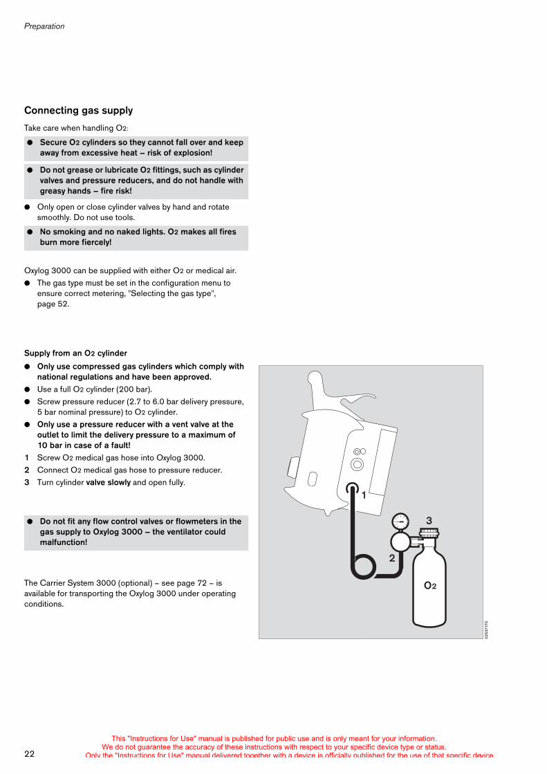
Take care when handling O2:
! Only open or close cylinder valves by hand and rotate smoothly. Do not use tools.
Oxylog 3000 can be supplied with either O2 or medical air. ! The gas type must be set in the configuration menu to
ensure correct metering, "Selecting the gas type", page 52.
Supply from an O2 cylinder
! Only use compressed gas cylinders which comply with national regulations and have been approved.
! Use a full O2 cylinder (200 bar).! Screw pressure reducer (2.7 to 6.0 bar delivery pressure,
5 bar nominal pressure) to O2 cylinder.! Only use a pressure reducer with a vent valve at the
outlet to limit the delivery pressure to a maximum of 10 bar in case of a fault!
1 Screw O2 medical gas hose into Oxylog 3000.2 Connect O2 medical gas hose to pressure reducer.3 Turn cylinder valve slowly and open fully.
The Carrier System 3000 (optional) – see page 72 – is available for transporting the Oxylog 3000 under operating conditions.
! Secure O2 cylinders so they cannot fall over and keep away from excessive heat – risk of explosion!
! Do not grease or lubricate O2 fittings, such as cylinder valves and pressure reducers, and do not handle with greasy hands – fire risk!
! No smoking and no naked lights. O2 makes all fires burn more fiercely!
! Do not fit any flow control valves or flowmeters in the gas supply to Oxylog 3000 – the ventilator could malfunction!
0253
7170
O2
1
2
3
This "Instructions for Use" manual is published for public use and is only meant for your information.We do not guarantee the accuracy of these instructions with respect to your specific device type or status.
Only the "Instructions for Use" manual delivered together with a device is officially published for the use of that specific device.
23
Preparation
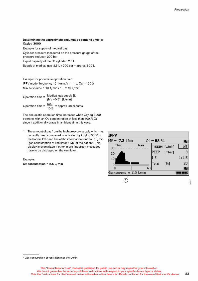
Determining the approximate pneumatic operating time for Oxylog 3000
Example for supply of medical gas:Cylinder pressure measured on the pressure gauge of the pressure reducer: 200 barLiquid capacity of the O2 cylinder: 2.5 LSupply of medical gas: 2.5 L x 200 bar = approx. 500 L
Example for pneumatic operation time:IPPV mode, frequency 10 1/min, VT = 1 L, O2 = 100 %Minute volume = 10 1/min x 1 L = 10 L/min
Operation time =
Operation time = = approx. 48 minutes
The pneumatic operation time increases when Oxylog 3000 operates with an O2 concentration of less than 100 % O2, since it additionally draws in ambient air in this case.
1 The amount of gas from the high-pressure supply which has currently been consumed is indicated by Oxylog 3000 in the bottom left-hand line of the information window in L/min (gas consumption of ventilator + MV of the patient). This display is overwritten if other, more important messages have to be displayed on the ventilator.
Example:O2 consumption = 2.5 L/min
__________* Gas consumption of ventilator: max. 0.5 L/min
1363
7171$
Medical gas supply [L](MV +0.5*) [L/min]50010.5
This "Instructions for Use" manual is published for public use and is only meant for your information.We do not guarantee the accuracy of these instructions with respect to your specific device type or status.
Only the "Instructions for Use" manual delivered together with a device is officially published for the use of that specific device.
Before using for the first time
24
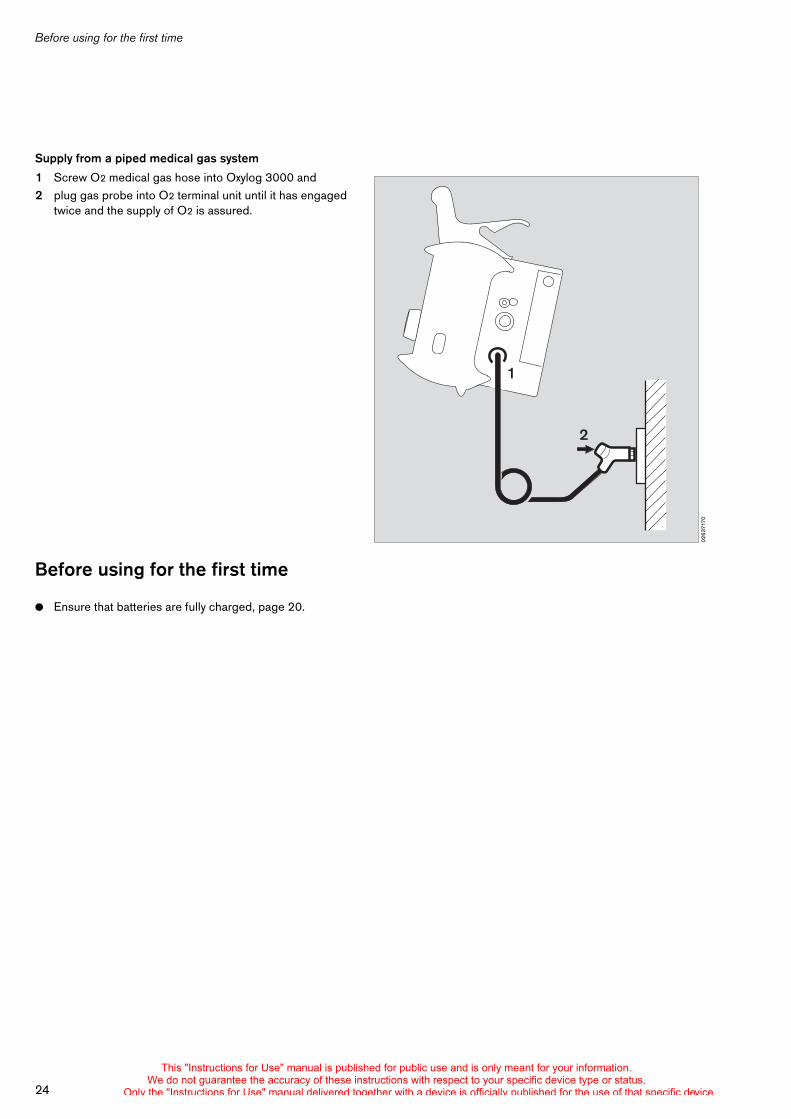
Supply from a piped medical gas system
1 Screw O2 medical gas hose into Oxylog 3000 and 2 plug gas probe into O2 terminal unit until it has engaged
twice and the supply of O2 is assured.
Before using for the first time
! Ensure that batteries are fully charged, page 20.
0263
7170
1
2
This "Instructions for Use" manual is published for public use and is only meant for your information.We do not guarantee the accuracy of these instructions with respect to your specific device type or status.
Only the "Instructions for Use" manual delivered together with a device is officially published for the use of that specific device.
Checking readiness for operation
25
Checking readiness for operation . . . . . . . . . . . . . . . . . . . . . . . . . . . . . . . . . . . . . . . 26
Connecting test lung . . . . . . . . . . . . . . . . . . . . . . . . . . . . . . . . . . . . . . . . . . . . . . . . 26
Perform device check . . . . . . . . . . . . . . . . . . . . . . . . . . . . . . . . . . . . . . . . . . . . . . . 26
Error messages during device check . . . . . . . . . . . . . . . . . . . . . . . . . . . . . . . . . . 30
Checking readiness for operation
This "Instructions for Use" manual is published for public use and is only meant for your information.We do not guarantee the accuracy of these instructions with respect to your specific device type or status.
Only the "Instructions for Use" manual delivered together with a device is officially published for the use of that specific device.
Checking readiness for operation
26
Checking readiness for operation
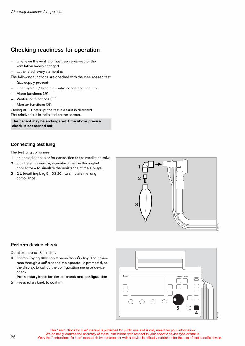
— whenever the ventilator has been prepared or the ventilation hoses changed
— at the latest every six months.The following functions are checked with the menu-based test:— Gas supply present— Hose system / breathing valve connected and OK— Alarm functions OK— Ventilation functions OK— Monitor functions OK.Oxylog 3000 interrupt the test if a fault is detected. The relative fault is indicated on the screen.
Connecting test lung
The test lung comprises:1 an angled connector for connection to the ventilation valve,2 a catheter connector, diameter 7 mm, in the angled
connector – to simulate the resistance of the airways.3 2 L breathing bag 84 03 201 to simulate the lung
compliance.
Perform device check
Duration: approx. 3 minutes.4 Switch Oxylog 3000 on = press the »O« key. The device
runs through a self-test and the operator is prompted, on the display, to call up the configuration menu or device check:Press rotary knob for device check and configuration
5 Press rotary knob to confirm.
The patient may be endangered if the above pre-use check is not carried out.
0403
7170
1
3
2
1083
7170
Oxylog 3000
54
This "Instructions for Use" manual is published for public use and is only meant for your information.We do not guarantee the accuracy of these instructions with respect to your specific device type or status.
Only the "Instructions for Use" manual delivered together with a device is officially published for the use of that specific device.
27
Checking readiness for operation
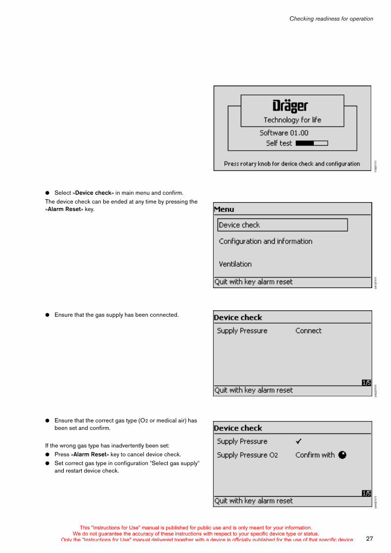
! Select »Device check« in main menu and confirm.The device check can be ended at any time by pressing the »Alarm Reset« key.
! Ensure that the gas supply has been connected.
! Ensure that the correct gas type (O2 or medical air) has been set and confirm.
If the wrong gas type has inadvertently been set:! Press »Alarm Reset« key to cancel device check.! Set correct gas type in configuration "Select gas supply"
and restart device check.
1193
7171
0413
7171
0423
7171
0443
7171
This "Instructions for Use" manual is published for public use and is only meant for your information.We do not guarantee the accuracy of these instructions with respect to your specific device type or status.
Only the "Instructions for Use" manual delivered together with a device is officially published for the use of that specific device.
Checking readiness for operation
28
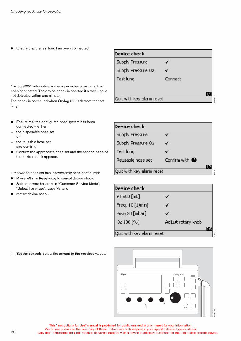
! Ensure that the test lung has been connected.
Oxylog 3000 automatically checks whether a test lung has been connected. The device check is aborted if a test lung is not detected within one minute.The check is continued when Oxylog 3000 detects the test lung.
! Ensure that the configured hose system has been connected – either:
— the disposable hose setor
— the reusable hose set and confirm.
! Confirm the appropriate hose set and the second page of the device check appears.
If the wrong hose set has inadvertently been configured:! Press »Alarm Reset« key to cancel device check.! Select correct hose set in "Customer Service Mode",
"Select hose type", page 78, and! restart device check.
1 Set the controls below the screen to the required values.
0433
7171
0453
7171
0473
7171
0483
7170
Oxylog 3000
1
This "Instructions for Use" manual is published for public use and is only meant for your information.We do not guarantee the accuracy of these instructions with respect to your specific device type or status.
Only the "Instructions for Use" manual delivered together with a device is officially published for the use of that specific device.
29
Checking readiness for operation
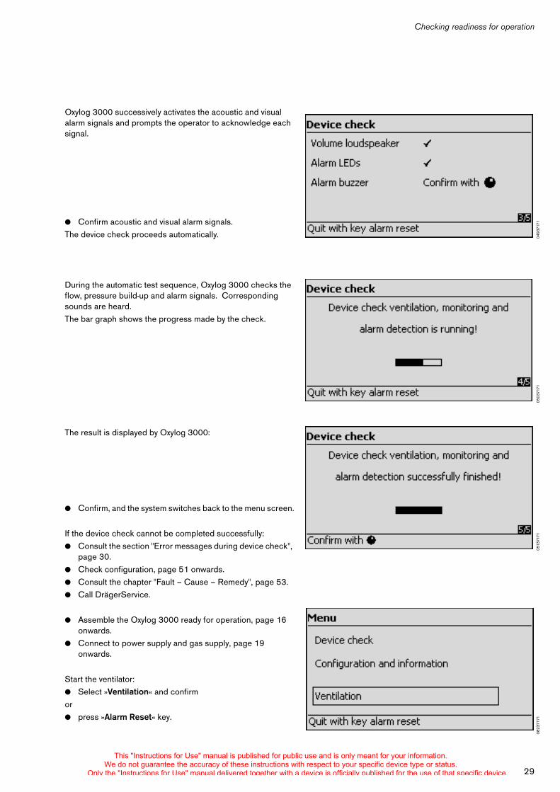
Oxylog 3000 successively activates the acoustic and visual alarm signals and prompts the operator to acknowledge each signal.
! Confirm acoustic and visual alarm signals.The device check proceeds automatically.
During the automatic test sequence, Oxylog 3000 checks the flow, pressure build-up and alarm signals. Corresponding sounds are heard.The bar graph shows the progress made by the check.
The result is displayed by Oxylog 3000:
! Confirm, and the system switches back to the menu screen.
If the device check cannot be completed successfully:! Consult the section "Error messages during device check",
page 30.! Check configuration, page 51 onwards.! Consult the chapter "Fault – Cause – Remedy", page 53.! Call DrägerService.
! Assemble the Oxylog 3000 ready for operation, page 16 onwards.
! Connect to power supply and gas supply, page 19 onwards.
Start the ventilator:! Select »Ventilation« and confirm or ! press »Alarm Reset« key.
0493
7171
0503
7171
0513
7171
0823
7171
This "Instructions for Use" manual is published for public use and is only meant for your information.We do not guarantee the accuracy of these instructions with respect to your specific device type or status.
Only the "Instructions for Use" manual delivered together with a device is officially published for the use of that specific device.
Checking readiness for operation
30
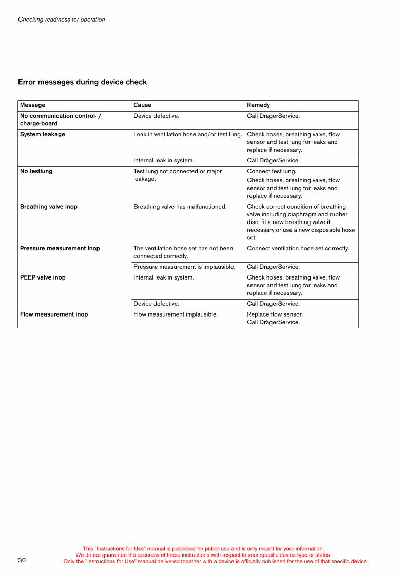
Error messages during device check
Message Cause Remedy
No communication control- / charge-board
Device defective. Call DrägerService.
System leakage Leak in ventilation hose and/or test lung. Check hoses, breathing valve, flow sensor and test lung for leaks and replace if necessary.
Internal leak in system. Call DrägerService.
No testlung Test lung not connected or major leakage.
Connect test lung.Check hoses, breathing valve, flow sensor and test lung for leaks and replace if necessary.
Breathing valve inop Breathing valve has malfunctioned. Check correct condition of breathing valve including diaphragm and rubber disc; fit a new breathing valve if necessary or use a new disposable hose set.
Pressure measurement inop The ventilation hose set has not been connected correctly.
Connect ventilation hose set correctly.
Pressure measurement is implausible. Call DrägerService.
PEEP valve inop Internal leak in system. Check hoses, breathing valve, flow sensor and test lung for leaks and replace if necessary.
Device defective. Call DrägerService.
Flow measurement inop Flow measurement implausible. Replace flow sensor. Call DrägerService.
This "Instructions for Use" manual is published for public use and is only meant for your information.We do not guarantee the accuracy of these instructions with respect to your specific device type or status.
Only the "Instructions for Use" manual delivered together with a device is officially published for the use of that specific device.
Operation
31
Operation . . . . . . . . . . . . . . . . . . . . . . . . . . . . . . . . . . . . . . . . . . . . . . . . . . . . . . . . . . . . 32
Starting operation . . . . . . . . . . . . . . . . . . . . . . . . . . . . . . . . . . . . . . . . . . . . . . . . . . . 32
Preparing ventilation mode . . . . . . . . . . . . . . . . . . . . . . . . . . . . . . . . . . . . . . . . . . . 32
IPPV (CMV), IPPVAssist (CMVAssist) . . . . . . . . . . . . . . . . . . . . . . . . . . . . . . . . . . 33
SIMV, SIMV/ASB (SIMV/PS) . . . . . . . . . . . . . . . . . . . . . . . . . . . . . . . . . . . . . . . . . 36
BIPAP (PCV+), BIPAP/ASB (PCV+/PS)* . . . . . . . . . . . . . . . . . . . . . . . . . . . . . . 37
CPAP, CPAP/ASB (CPAP/PS) . . . . . . . . . . . . . . . . . . . . . . . . . . . . . . . . . . . . . . . 38
Apnoea ventilation . . . . . . . . . . . . . . . . . . . . . . . . . . . . . . . . . . . . . . . . . . . . . . . . . . 39
NIV – Non-invasive ventilation Mask ventilation . . . . . . . . . . . . . . . . . . . . . . . . . . 41
O2 concentration without optional "O2 blending" . . . . . . . . . . . . . . . . . . . . . . . . 42
O2 concentration with optional "O2 blending" (40 % to 100 %) . . . . . . . . . . . . 42
Setting alarm limits . . . . . . . . . . . . . . . . . . . . . . . . . . . . . . . . . . . . . . . . . . . . . . . . . . 44
In the Event of an Alarm . . . . . . . . . . . . . . . . . . . . . . . . . . . . . . . . . . . . . . . . . . . . . . 45
Warning . . . . . . . . . . . . . . . . . . . . . . . . . . . . . . . . . . . . . . . . . . . . . . . . . . . . . . . . . . . 45
Caution . . . . . . . . . . . . . . . . . . . . . . . . . . . . . . . . . . . . . . . . . . . . . . . . . . . . . . . . . . . . 45
Advisory . . . . . . . . . . . . . . . . . . . . . . . . . . . . . . . . . . . . . . . . . . . . . . . . . . . . . . . . . . . 46
Suppress alarm tones . . . . . . . . . . . . . . . . . . . . . . . . . . . . . . . . . . . . . . . . . . . . . . . 46
In the event of a gas failure . . . . . . . . . . . . . . . . . . . . . . . . . . . . . . . . . . . . . . . . . . . 46
Displaying curves and measured values . . . . . . . . . . . . . . . . . . . . . . . . . . . . . . . 47
Special functions . . . . . . . . . . . . . . . . . . . . . . . . . . . . . . . . . . . . . . . . . . . . . . . . . . . 48
Calibration . . . . . . . . . . . . . . . . . . . . . . . . . . . . . . . . . . . . . . . . . . . . . . . . . . . . . . . . . 50
Screen brightness . . . . . . . . . . . . . . . . . . . . . . . . . . . . . . . . . . . . . . . . . . . . . . . . . . 50
Shutdown . . . . . . . . . . . . . . . . . . . . . . . . . . . . . . . . . . . . . . . . . . . . . . . . . . . . . . . . . . 50
Displaying configuration and information . . . . . . . . . . . . . . . . . . . . . . . . . . . . . . . 51
Operation
This "Instructions for Use" manual is published for public use and is only meant for your information.We do not guarantee the accuracy of these instructions with respect to your specific device type or status.
Only the "Instructions for Use" manual delivered together with a device is officially published for the use of that specific device.
Operation
32
Operation
Check readiness for operation, page 26.
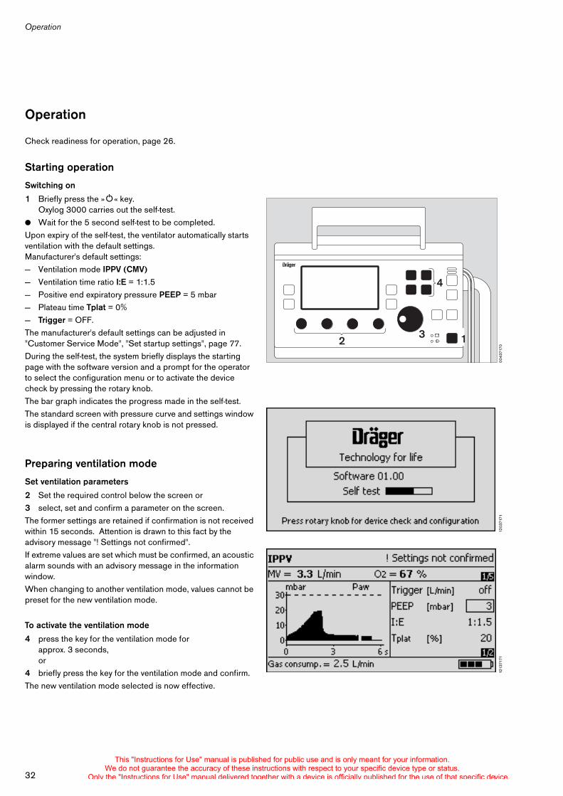
Starting operation
Switching on
1 Briefly press the »O« key.Oxylog 3000 carries out the self-test.
! Wait for the 5 second self-test to be completed. Upon expiry of the self-test, the ventilator automatically starts ventilation with the default settings. Manufacturer's default settings: — Ventilation mode IPPV (CMV)— Ventilation time ratio I:E = 1:1.5— Positive end expiratory pressure PEEP = 5 mbar— Plateau time Tplat = 0%— Trigger = OFF.The manufacturer's default settings can be adjusted in "Customer Service Mode", "Set startup settings", page 77.During the self-test, the system briefly displays the starting page with the software version and a prompt for the operator to select the configuration menu or to activate the device check by pressing the rotary knob.The bar graph indicates the progress made in the self-test.The standard screen with pressure curve and settings window is displayed if the central rotary knob is not pressed.
Preparing ventilation mode
Set ventilation parameters
2 Set the required control below the screen or 3 select, set and confirm a parameter on the screen.The former settings are retained if confirmation is not received within 15 seconds. Attention is drawn to this fact by the advisory message "! Settings not confirmed".If extreme values are set which must be confirmed, an acoustic alarm sounds with an advisory message in the information window.When changing to another ventilation mode, values cannot be preset for the new ventilation mode.
To activate the ventilation mode
4 press the key for the ventilation mode for approx. 3 seconds,or
4 briefly press the key for the ventilation mode and confirm.The new ventilation mode selected is now effective.
0043
7170
4
3 12
1203
7171
1213
7171
This "Instructions for Use" manual is published for public use and is only meant for your information.We do not guarantee the accuracy of these instructions with respect to your specific device type or status.
Only the "Instructions for Use" manual delivered together with a device is officially published for the use of that specific device.
33
Operation
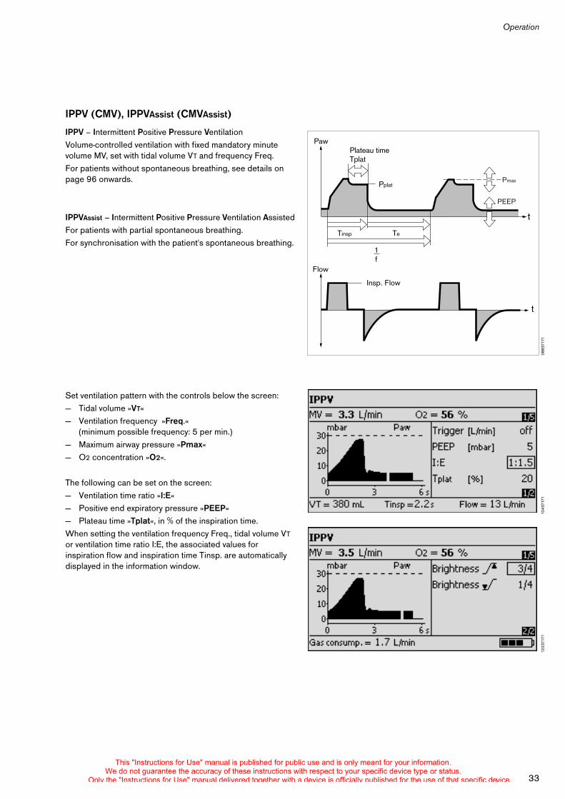
IPPV (CMV), IPPVAssist (CMVAssist)
IPPV – Intermittent Positive Pressure Ventilation Volume-controlled ventilation with fixed mandatory minute volume MV, set with tidal volume VT and frequency Freq.For patients without spontaneous breathing, see details on page 96 onwards.
IPPVAssist – Intermittent Positive Pressure Ventilation Assisted For patients with partial spontaneous breathing. For synchronisation with the patient's spontaneous breathing.
Set ventilation pattern with the controls below the screen: — Tidal volume »VT«— Ventilation frequency »Freq.«
(minimum possible frequency: 5 per min.)— Maximum airway pressure »Pmax«— O2 concentration »O2«.
The following can be set on the screen: — Ventilation time ratio »I:E«— Positive end expiratory pressure »PEEP«— Plateau time »Tplat«, in % of the inspiration time.When setting the ventilation frequency Freq., tidal volume VT or ventilation time ratio I:E, the associated values for inspiration flow and inspiration time Tinsp. are automatically displayed in the information window.
0883
7171
Paw
Flow
Tinsp Te
Pplat
Plateau timeTplat
1f
Insp. Flow
t
t
Pmax
PEEP
1043
7171
1223
7171
This "Instructions for Use" manual is published for public use and is only meant for your information.We do not guarantee the accuracy of these instructions with respect to your specific device type or status.
Only the "Instructions for Use" manual delivered together with a device is officially published for the use of that specific device.
Operation
34
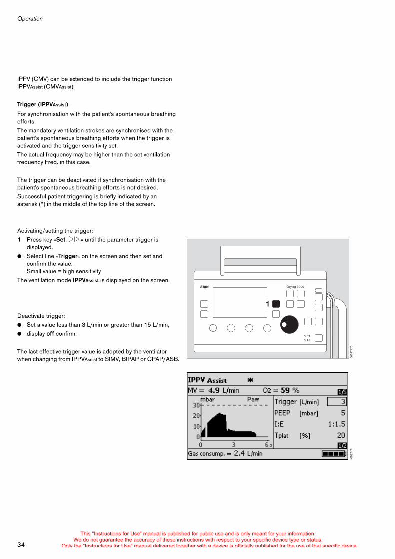
IPPV (CMV) can be extended to include the trigger function IPPVAssist (CMVAssist):
Trigger (IPPVAssist)
For synchronisation with the patient's spontaneous breathing efforts.The mandatory ventilation strokes are synchronised with the patient's spontaneous breathing efforts when the trigger is activated and the trigger sensitivity set.The actual frequency may be higher than the set ventilation frequency Freq. in this case.
The trigger can be deactivated if synchronisation with the patient's spontaneous breathing efforts is not desired.Successful patient triggering is briefly indicated by an asterisk (*) in the middle of the top line of the screen.
Activating/setting the trigger: 1 Press key »Set. !! « until the parameter trigger is
displayed. ! Select line »Trigger« on the screen and then set and
confirm the value.Small value = high sensitivity
The ventilation mode IPPVAssist is displayed on the screen.
Deactivate trigger:! Set a value less than 3 L/min or greater than 15 L/min,! display off confirm.
The last effective trigger value is adopted by the ventilator when changing from IPPVAssist to SIMV, BIPAP or CPAP/ASB. 00
5371
70
Oxylog 3000
1
1053
7171
This "Instructions for Use" manual is published for public use and is only meant for your information.We do not guarantee the accuracy of these instructions with respect to your specific device type or status.
Only the "Instructions for Use" manual delivered together with a device is officially published for the use of that specific device.
35
Operation
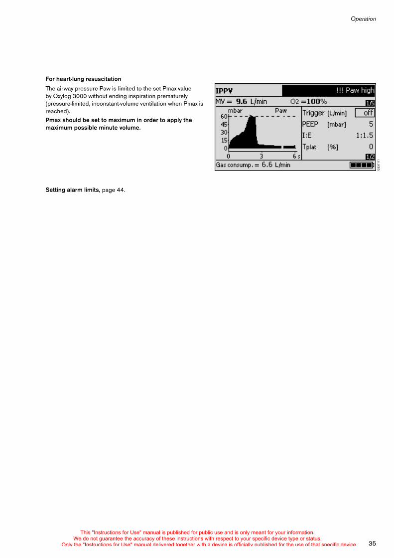
For heart-lung resuscitation
The airway pressure Paw is limited to the set Pmax value by Oxylog 3000 without ending inspiration prematurely (pressure-limited, inconstant-volume ventilation when Pmax is reached).Pmax should be set to maximum in order to apply the maximum possible minute volume.
Setting alarm limits, page 44.
1233
7171
This "Instructions for Use" manual is published for public use and is only meant for your information.We do not guarantee the accuracy of these instructions with respect to your specific device type or status.
Only the "Instructions for Use" manual delivered together with a device is officially published for the use of that specific device.
Operation
36
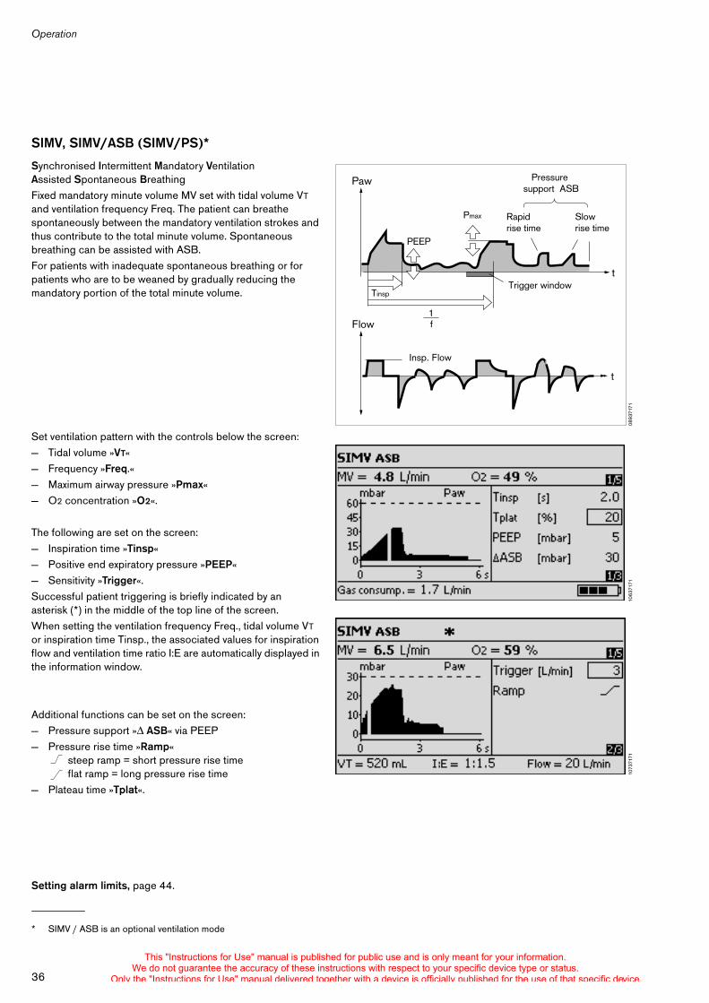
SIMV, SIMV/ASB (SIMV/PS)*
Synchronised Intermittent Mandatory VentilationAssisted Spontaneous Breathing Fixed mandatory minute volume MV set with tidal volume VT and ventilation frequency Freq. The patient can breathe spontaneously between the mandatory ventilation strokes and thus contribute to the total minute volume. Spontaneous breathing can be assisted with ASB.For patients with inadequate spontaneous breathing or for patients who are to be weaned by gradually reducing the mandatory portion of the total minute volume.
Set ventilation pattern with the controls below the screen: — Tidal volume »VT«— Frequency »Freq.«— Maximum airway pressure »Pmax«— O2 concentration »O2«.
The following are set on the screen:— Inspiration time »Tinsp«— Positive end expiratory pressure »PEEP«— Sensitivity »Trigger«.Successful patient triggering is briefly indicated by an asterisk (*) in the middle of the top line of the screen.When setting the ventilation frequency Freq., tidal volume VT or inspiration time Tinsp., the associated values for inspiration flow and ventilation time ratio I:E are automatically displayed in the information window.
Additional functions can be set on the screen: — Pressure support » ASB« via PEEP— Pressure rise time »Ramp«
steep ramp = short pressure rise time flat ramp = long pressure rise time
— Plateau time »Tplat«.
Setting alarm limits, page 44.
* SIMV / ASB is an optional ventilation mode
0893
7171
Paw
Flow
Tinsp
Pmax
PEEP
Rapid rise time
Slow rise time
Pressure support ASB
Trigger window
f
Insp. Flow
t
t
1
1063
7171
1073
7171
This "Instructions for Use" manual is published for public use and is only meant for your information.We do not guarantee the accuracy of these instructions with respect to your specific device type or status.
Only the "Instructions for Use" manual delivered together with a device is officially published for the use of that specific device.
37
Operation
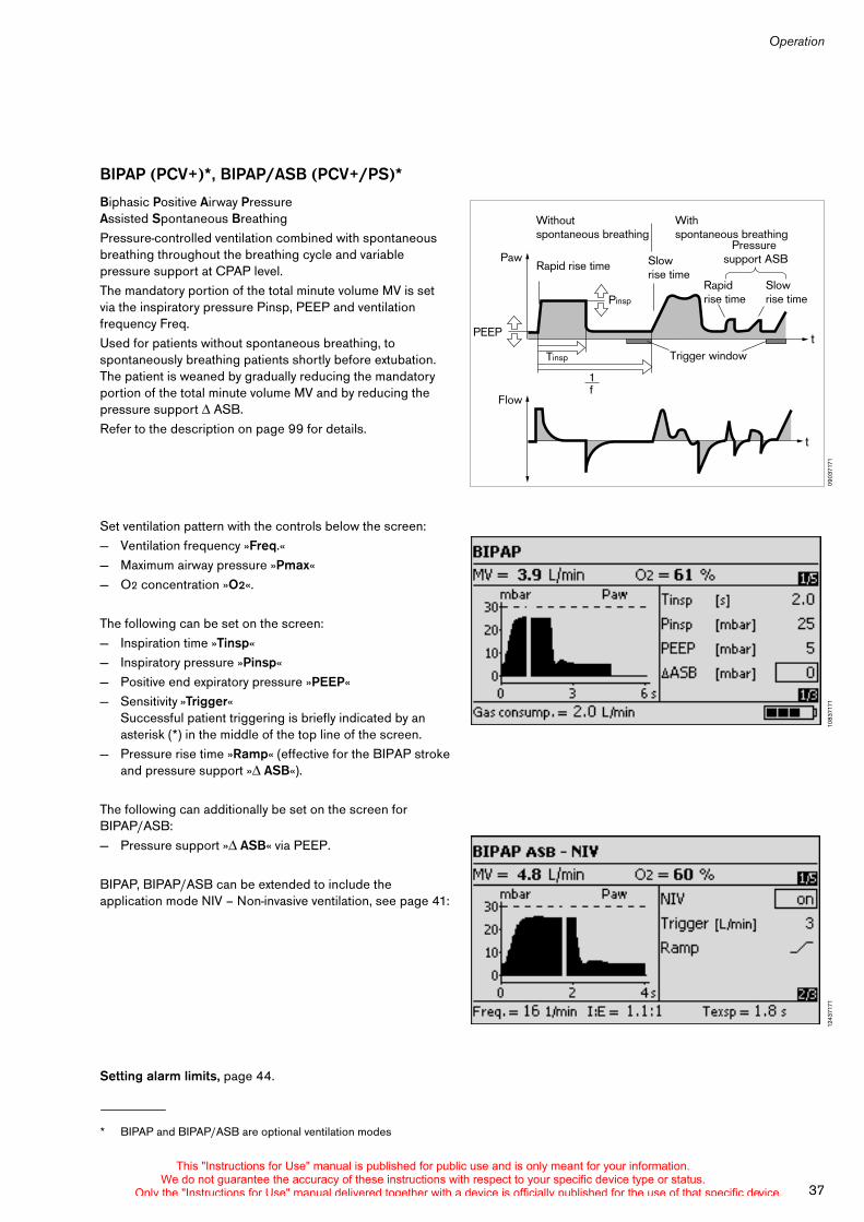
BIPAP (PCV+)*, BIPAP/ASB (PCV+/PS)*
Biphasic Positive Airway PressureAssisted Spontaneous Breathing Pressure-controlled ventilation combined with spontaneous breathing throughout the breathing cycle and variable pressure support at CPAP level.The mandatory portion of the total minute volume MV is set via the inspiratory pressure Pinsp, PEEP and ventilation frequency Freq.Used for patients without spontaneous breathing, to spontaneously breathing patients shortly before extubation. The patient is weaned by gradually reducing the mandatory portion of the total minute volume MV and by reducing the pressure support ASB.Refer to the description on page 99 for details.
Set ventilation pattern with the controls below the screen: — Ventilation frequency »Freq.«— Maximum airway pressure »Pmax«— O2 concentration »O2«.
The following can be set on the screen:— Inspiration time »Tinsp«— Inspiratory pressure »Pinsp«— Positive end expiratory pressure »PEEP«— Sensitivity »Trigger«
Successful patient triggering is briefly indicated by an asterisk (*) in the middle of the top line of the screen.
— Pressure rise time »Ramp« (effective for the BIPAP stroke and pressure support » ASB«).
The following can additionally be set on the screen for BIPAP/ASB: — Pressure support » ASB« via PEEP.
BIPAP, BIPAP/ASB can be extended to include the application mode NIV – Non-invasive ventilation, see page 41:
Setting alarm limits, page 44.
* BIPAP and BIPAP/ASB are optional ventilation modes
0903
7171
Paw
Flow
Pinsp
PEEP
Slow rise time
Rapid rise time
t
tTinsp
Rapid rise time
Slow rise time
Pressure support ASB
Trigger window
f1
Without spontaneous breathing
With spontaneous breathing
1083
7171
1243
7171
This "Instructions for Use" manual is published for public use and is only meant for your information.We do not guarantee the accuracy of these instructions with respect to your specific device type or status.
Only the "Instructions for Use" manual delivered together with a device is officially published for the use of that specific device.
Operation
38
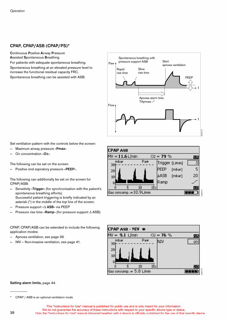
CPAP, CPAP/ASB (CPAP/PS)*
Continuous Positive Airway Pressure Assisted Spontaneous Breathing For patients with adequate spontaneous breathing.Spontaneous breathing at an elevated pressure level to increase the functional residual capacity FRC.Spontaneous breathing can be assisted with ASB.
Set ventilation pattern with the controls below the screen: — Maximum airway pressure »Pmax«— O2 concentration »O2«.
The following can be set on the screen:— Positive end expiratory pressure »PEEP«.
The following can additionally be set on the screen for CPAP/ASB:— Sensitivity »Trigger« (for synchronisation with the patient's
spontaneous breathing efforts).Successful patient triggering is briefly indicated by an asterisk (*) in the middle of the top line of the screen.
— Pressure support » ASB« via PEEP— Pressure rise time »Ramp« (for pressure support ASB)
CPAP, CPAP/ASB can be extended to include the following application modes:— Apnoea ventilation, see page 39.— NIV – Non-invasive ventilation, see page 41.
Setting alarm limits, page 44.
* CPAP / ASB is an optional ventilation mode
0913
7171
Paw
Flow
Apnoea alarm time TApnoea >
Start apnoea ventilation
t
t
PEEP
Rapid rise time
Slow rise time
Spontaneous breathing with pressure support ASB
1253
7171
1263
7171
This "Instructions for Use" manual is published for public use and is only meant for your information.We do not guarantee the accuracy of these instructions with respect to your specific device type or status.
Only the "Instructions for Use" manual delivered together with a device is officially published for the use of that specific device.
39
Operation
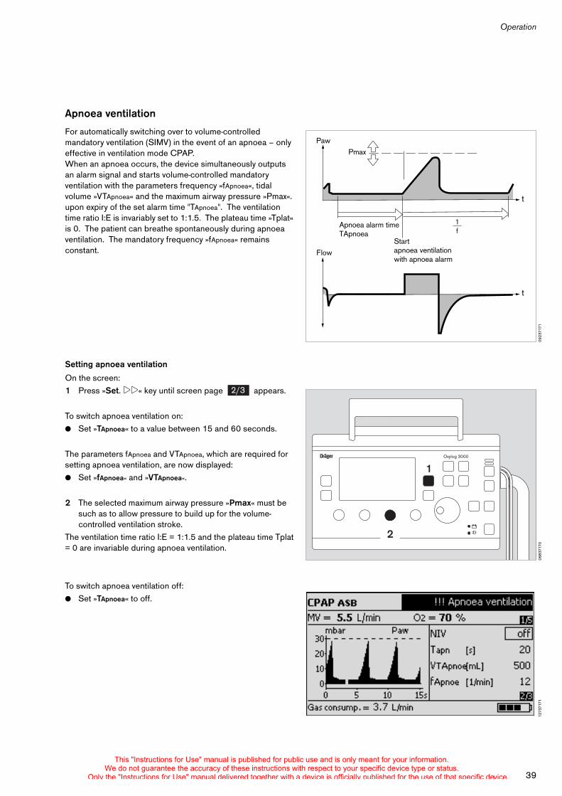
Apnoea ventilation
For automatically switching over to volume-controlled mandatory ventilation (SIMV) in the event of an apnoea – only effective in ventilation mode CPAP.When an apnoea occurs, the device simultaneously outputs an alarm signal and starts volume-controlled mandatory ventilation with the parameters frequency »fApnoea«, tidal volume »VTApnoea« and the maximum airway pressure »Pmax«. upon expiry of the set alarm time "TApnoea". The ventilation time ratio I:E is invariably set to 1:1.5. The plateau time »Tplat« is 0. The patient can breathe spontaneously during apnoea ventilation. The mandatory frequency »fApnoea« remains constant.
Setting apnoea ventilation
On the screen:1 Press »Set. !!« key until screen page appears.
To switch apnoea ventilation on:! Set »TApnoea« to a value between 15 and 60 seconds.
The parameters fApnoea and VTApnoea, which are required for setting apnoea ventilation, are now displayed:! Set »fApnoea« and »VTApnoea«.
2 The selected maximum airway pressure »Pmax« must be such as to allow pressure to build up for the volume-controlled ventilation stroke.
The ventilation time ratio I:E = 1:1.5 and the plateau time Tplat = 0 are invariable during apnoea ventilation.
To switch apnoea ventilation off:! Set »TApnoea« to off.
0923
7171
Paw
Flow
Apnoea alarm timeTApnoea
Start apnoea ventilationwith apnoea alarm
t
t
1f
Pmax
0683
7170
Oxylog 3000
2
1
2/3
1273
7171
This "Instructions for Use" manual is published for public use and is only meant for your information.We do not guarantee the accuracy of these instructions with respect to your specific device type or status.
Only the "Instructions for Use" manual delivered together with a device is officially published for the use of that specific device.
Operation
40
To end apnoea ventilation: ! Press the »Alarm Reset« key.The ventilator continues operation with the original ventilation mode and with the original ventilation parameters set (CPAP).
The manufacturer's settings fApnoea = 12 1/min and VTApnoea = 500 ml can be changed in "Customer Service Mode", see page 77.
Apnoea ventilation can only be activated in ventilation mode CPAP without NIV. Apnoea ventilation is not available in any of the other pressure-controlled ventilation forms. ! The minimum ventilation required by the patient must be
assured via the lower alarm limit MV .
Setting alarm limits, page 44.
This "Instructions for Use" manual is published for public use and is only meant for your information.We do not guarantee the accuracy of these instructions with respect to your specific device type or status.
Only the "Instructions for Use" manual delivered together with a device is officially published for the use of that specific device.
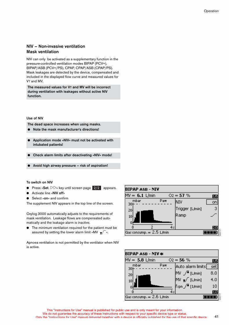
41
Operation
NIV – Non-invasive ventilation Mask ventilation
NIV can only be activated as a supplementary function in the pressure-controlled ventilation modes BIPAP (PCV+), BIPAP/ASB (PCV+/PS), CPAP, CPAP/ASB (CPAP/PS). Mask leakages are detected by the device, compensated and included in the displayed flow curve and measured values for VT and MV.
Use of NIV
To switch on NIV
! Press »Set. !!« key until screen page appears.! Activate line »NIV off« ! Select »on« and confirmThe supplement NIV appears in the top line of the screen.
Oxylog 3000 automatically adjusts to the requirements of mask ventilation. Leakage flows are compensated auto-matically and the leakage alarm is inactive. ! The minimum ventilation required for the patient must be
assured by setting the lower alarm limit »MV «.
Apnoea ventilation is not permitted by the ventilator when NIV is active.
The measured values for VT and MV will be incorrect during ventilation with leakages without active NIV function.
The dead space increases when using masks.! Note the mask manufacturer's directions!
! Application mode »NIV« must not be activated with intubated patients!
! Check alarm limits after deactivating »NIV« mode!
! Avoid high airway pressure – risk of aspiration!
1283
7171
2/2
1293
7171
This "Instructions for Use" manual is published for public use and is only meant for your information.We do not guarantee the accuracy of these instructions with respect to your specific device type or status.
Only the "Instructions for Use" manual delivered together with a device is officially published for the use of that specific device.
Operation
42
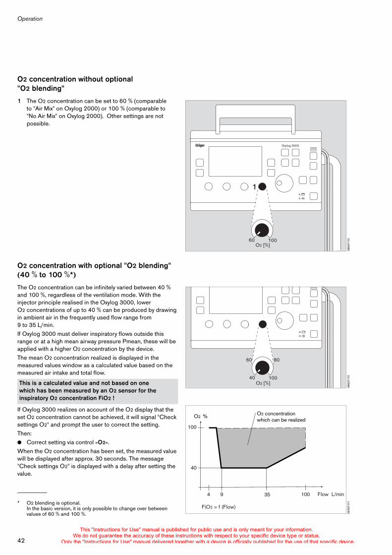
O2 concentration without optional "O2 blending"
1 The O2 concentration can be set to 60 % (comparable to "Air Mix" on Oxylog 2000) or 100 % (comparable to "No Air Mix" on Oxylog 2000). Other settings are not possible.
O2 concentration with optional "O2 blending" (40 % to 100 %*)
The O2 concentration can be infinitely varied between 40 % and 100 %, regardless of the ventilation mode. With the injector principle realised in the Oxylog 3000, lower O2 concentrations of up to 40 % can be produced by drawing in ambient air in the frequently used flow range from 9 to 35 L/min.If Oxylog 3000 must deliver inspiratory flows outside this range or at a high mean airway pressure Pmean, these will be applied with a higher O2 concentration by the device.The mean O2 concentration realized is displayed in the measured values window as a calculated value based on the measured air intake and total flow.
If Oxylog 3000 realizes on account of the O2 display that the set O2 concentration cannot be achieved, it will signal "Check settings O2" and prompt the user to correct the setting. Then: ! Correct setting via control »O2«.When the O2 concentration has been set, the measured value will be displayed after approx. 30 seconds. The message "Check settings O2" is displayed with a delay after setting the value.
* O2 blending is optional.In the basic version, it is only possible to change over between values of 60 % and 100 %.
This is a calculated value and not based on one which has been measured by an O2 sensor for the inspiratory O2 concentration FiO2 !
0863
7170
Oxylog 3000
1
60O2 [%]
100
0863
717040
60 80
O2 [%]100
0933
7171
O2 % O2 concentration which can be realized
Flow L/min
100
40
1004 9 35
FiO2 = f (Flow)
This "Instructions for Use" manual is published for public use and is only meant for your information.We do not guarantee the accuracy of these instructions with respect to your specific device type or status.
Only the "Instructions for Use" manual delivered together with a device is officially published for the use of that specific device.
43
Operation
When patients who are spontaneously breathing, the achievable O2 concentration will depend on the profile of the inspiratory flow. Even if this profile is changed, the message "Check settings O2" may appear after some time.
In toxic surroundings:! the patient must be ventilated with 100 % O2 in order
to ensure that toxic constituents are not entrained into the breathing gas.
! The patient must immediately be transferred to a breathable atmosphere in order to prevent inhalation of toxic air when spontaneous breathing resumes.
This "Instructions for Use" manual is published for public use and is only meant for your information.We do not guarantee the accuracy of these instructions with respect to your specific device type or status.
Only the "Instructions for Use" manual delivered together with a device is officially published for the use of that specific device.
Operation
44
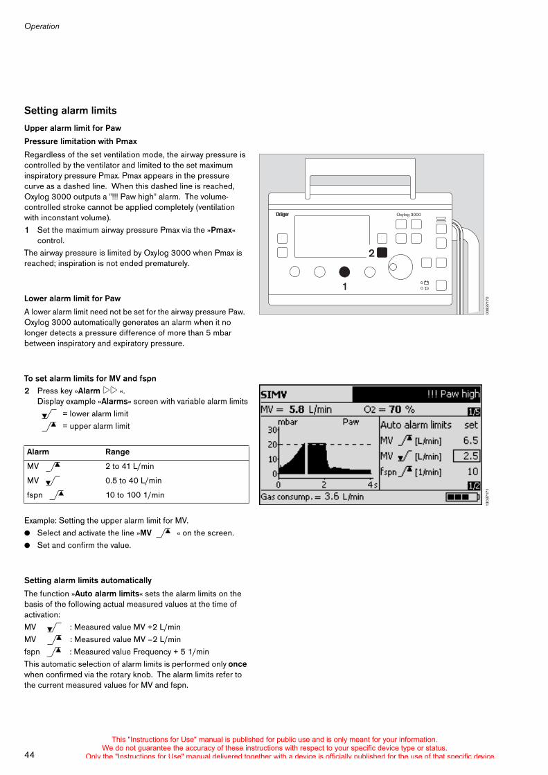
Setting alarm limits
Upper alarm limit for Paw
Pressure limitation with Pmax
Regardless of the set ventilation mode, the airway pressure is controlled by the ventilator and limited to the set maximum inspiratory pressure Pmax. Pmax appears in the pressure curve as a dashed line. When this dashed line is reached, Oxylog 3000 outputs a "!!! Paw high" alarm. The volume-controlled stroke cannot be applied completely (ventilation with inconstant volume).1 Set the maximum airway pressure Pmax via the »Pmax«
control.The airway pressure is limited by Oxylog 3000 when Pmax is reached; inspiration is not ended prematurely.
Lower alarm limit for Paw
A lower alarm limit need not be set for the airway pressure Paw. Oxylog 3000 automatically generates an alarm when it no longer detects a pressure difference of more than 5 mbar between inspiratory and expiratory pressure.
To set alarm limits for MV and fspn2 Press key »Alarm !! «.
Display example »Alarms« screen with variable alarm limits = lower alarm limit
= upper alarm limit
Example: Setting the upper alarm limit for MV. ! Select and activate the line »MV « on the screen.! Set and confirm the value.
Setting alarm limits automatically
The function »Auto alarm limits« sets the alarm limits on the basis of the following actual measured values at the time of activation:MV : Measured value MV +2 L/minMV : Measured value MV –2 L/minfspn : Measured value Frequency + 5 1/minThis automatic selection of alarm limits is performed only once when confirmed via the rotary knob. The alarm limits refer to the current measured values for MV and fspn.
Alarm Range
MV 2 to 41 L/min
MV 0.5 to 40 L/min
fspn 10 to 100 1/min00
6371
70
Oxylog 3000
2
1
1303
7171
This "Instructions for Use" manual is published for public use and is only meant for your information.We do not guarantee the accuracy of these instructions with respect to your specific device type or status.
Only the "Instructions for Use" manual delivered together with a device is officially published for the use of that specific device.
45
Operation
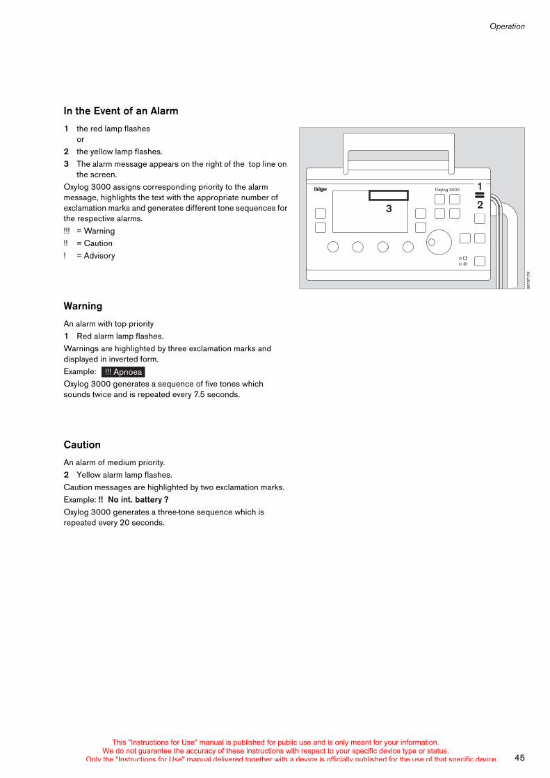
In the Event of an Alarm
1 the red lamp flashesor
2 the yellow lamp flashes.3 The alarm message appears on the right of the top line on
the screen.Oxylog 3000 assigns corresponding priority to the alarm message, highlights the text with the appropriate number of exclamation marks and generates different tone sequences for the respective alarms.!!! = Warning!! = Caution! = Advisory
Warning
An alarm with top priority 1 Red alarm lamp flashes.Warnings are highlighted by three exclamation marks and displayed in inverted form. Example: Oxylog 3000 generates a sequence of five tones which sounds twice and is repeated every 7.5 seconds.
Caution
An alarm of medium priority. 2 Yellow alarm lamp flashes.Caution messages are highlighted by two exclamation marks. Example: !! No int. battery ? Oxylog 3000 generates a three-tone sequence which is repeated every 20 seconds.
0073
7170
Oxylog 3000
2
1
3
!!! Apnoea
This "Instructions for Use" manual is published for public use and is only meant for your information.We do not guarantee the accuracy of these instructions with respect to your specific device type or status.
Only the "Instructions for Use" manual delivered together with a device is officially published for the use of that specific device.
Operation
46
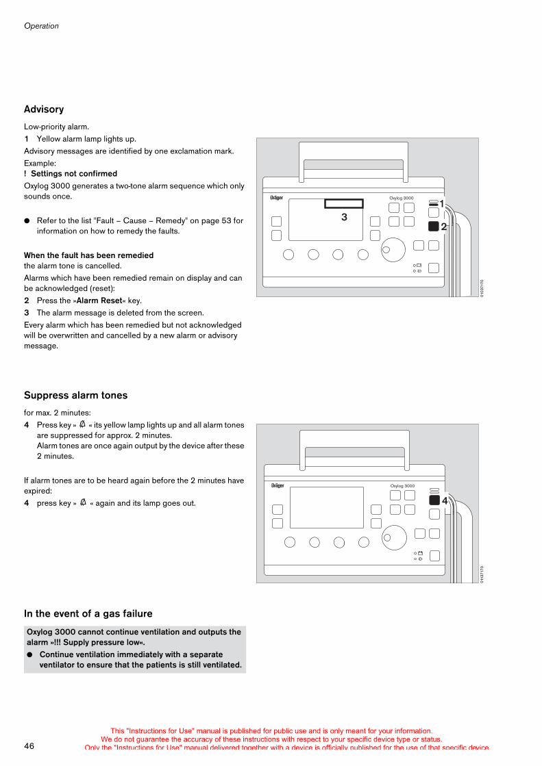
Advisory
Low-priority alarm.1 Yellow alarm lamp lights up.Advisory messages are identified by one exclamation mark. Example:! Settings not confirmedOxylog 3000 generates a two-tone alarm sequence which only sounds once.
! Refer to the list "Fault – Cause – Remedy" on page 53 for information on how to remedy the faults.
When the fault has been remediedthe alarm tone is cancelled. Alarms which have been remedied remain on display and can be acknowledged (reset): 2 Press the »Alarm Reset« key.3 The alarm message is deleted from the screen.Every alarm which has been remedied but not acknowledged will be overwritten and cancelled by a new alarm or advisory message.
Suppress alarm tones
for max. 2 minutes: 4 Press key » g « its yellow lamp lights up and all alarm tones
are suppressed for approx. 2 minutes. Alarm tones are once again output by the device after these 2 minutes.
If alarm tones are to be heard again before the 2 minutes have expired:4 press key » g « again and its lamp goes out.
In the event of a gas failure
Oxylog 3000 cannot continue ventilation and outputs the alarm »!!! Supply pressure low«. ! Continue ventilation immediately with a separate
ventilator to ensure that the patients is still ventilated.
0103
7170
Oxylog 3000
32
1
0113
7170
Oxylog 3000
4
This "Instructions for Use" manual is published for public use and is only meant for your information.We do not guarantee the accuracy of these instructions with respect to your specific device type or status.
Only the "Instructions for Use" manual delivered together with a device is officially published for the use of that specific device.
47
Operation
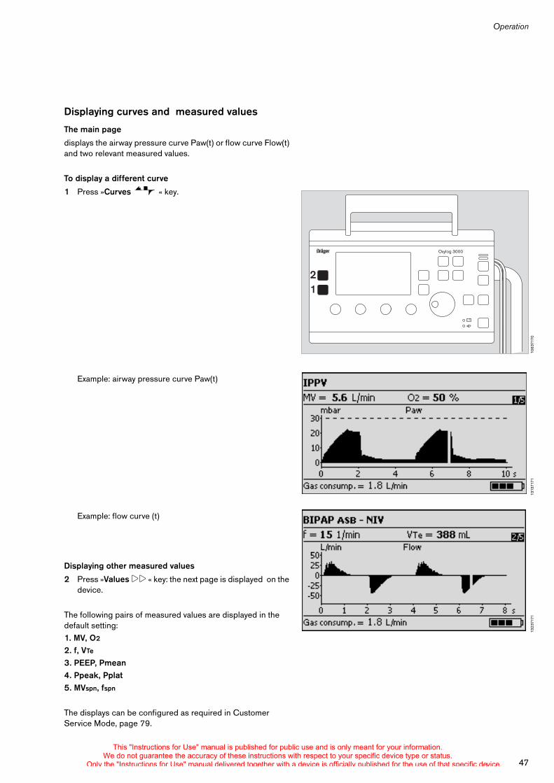
Displaying curves and measured values
The main page
displays the airway pressure curve Paw(t) or flow curve Flow(t) and two relevant measured values.
To display a different curve
1 Press »Curves « key.
Example: airway pressure curve Paw(t)
Example: flow curve (t)
Displaying other measured values
2 Press »Values !! « key: the next page is displayed on the device.
The following pairs of measured values are displayed in the default setting:1. MV, O2
2. f, VTe
3. PEEP, Pmean4. Ppeak, Pplat5. MVspn, fspn
The displays can be configured as required in Customer Service Mode, page 79.
1063
7170
Oxylog 3000
21
1313
7171
1323
7171
This "Instructions for Use" manual is published for public use and is only meant for your information.We do not guarantee the accuracy of these instructions with respect to your specific device type or status.
Only the "Instructions for Use" manual delivered together with a device is officially published for the use of that specific device.
Operation
48
Special functions
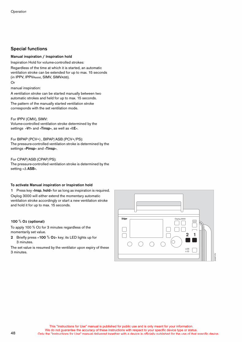
Manual inspiration / Inspiration hold
Inspiration Hold for volume-controlled strokes:Regardless of the time at which it is started, an automatic ventilation stroke can be extended for up to max. 15 seconds (in IPPV, IPPVAssist, SIMV, SIMVASB).Ormanual inspiration:A ventilation stroke can be started manually between two automatic strokes and held for up to max. 15 seconds.The pattern of the manually started ventilation stroke corresponds with the set ventilation mode.
For IPPV (CMV), SIMV:Volume-controlled ventilation stroke determined by the settings »VT« and »Tinsp«, as well as »I:E«.
For BIPAP (PCV+) , BIPAP/ASB (PCV+/PS):The pressure-controlled ventilation stroke is determined by the settings »Pinsp« and »Tinsp«.
For CPAP/ASB (CPAP/PS):The pressure-controlled ventilation stroke is determined by the setting » ASB«.
To activate Manual inspiration or Inspiration hold1 Press key »Insp. hold« for as long as inspiration is required.Oxylog 3000 will either extend the momentary automatic ventilation stroke accordingly or start a new ventilation stroke and hold it for up to max. 15 seconds.
100 % O2 (optional)
To apply 100 % O2 for 3 minutes regardless of the momentarily set value.2 Briefly press »100 % O2« key; its LED lights up for
3 minutes.The set value is resumed by the ventilator upon expiry of these 3 minutes.
0123
7170
Oxylog 3000
12
This "Instructions for Use" manual is published for public use and is only meant for your information.We do not guarantee the accuracy of these instructions with respect to your specific device type or status.
Only the "Instructions for Use" manual delivered together with a device is officially published for the use of that specific device.
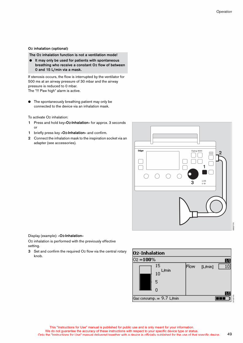
49
Operation
O2 inhalation (optional)
If stenosis occurs, the flow is interrupted by the ventilator for 500 ms at an airway pressure of 30 mbar and the airway pressure is reduced to 0 mbar. The "!!! Paw high" alarm is active.
! The spontaneously breathing patient may only be connected to the device via an inhalation mask.
To activate O2 inhalation:1 Press and hold key»O2-Inhalation« for approx. 3 seconds
or1 briefly press key »O2-Inhalation« and confirm. 2 Connect the inhalation mask to the inspiration socket via an
adapter (see accessories).
Display (example): »O2-Inhalation«O2 inhalation is performed with the previously effective setting.3 Set and confirm the required O2 flow via the central rotary
knob.
The O2 inhalation function is not a ventilation mode!! It may only be used for patients with spontaneous
breathing who receive a constant O2 flow of between 0 and 15 L/min via a mask.
0833
7170
Oxylog 3000
1
2
3
0713
7170
This "Instructions for Use" manual is published for public use and is only meant for your information.We do not guarantee the accuracy of these instructions with respect to your specific device type or status.
Only the "Instructions for Use" manual delivered together with a device is officially published for the use of that specific device.
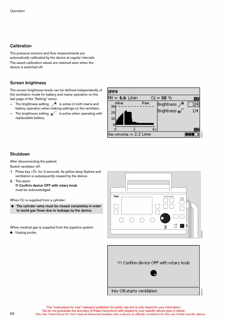
Operation
50
Calibration
The pressure sensors and flow measurements are automatically calibrated by the device at regular intervals.The saved calibration values are retained even when the device is switched off.
Screen brightness
The screen brightness levels can be defined independently of the ventilation mode for battery and mains operation on the last page of the "Setting" menu:— The brightness setting is active in both mains and
battery operation when making settings on the ventilator.— The brightness setting is active when operating with
replaceable battery.
Shutdown
After disconnecting the patient:Switch ventilator off: 1 Press key »O« for 3 seconds. Its yellow lamp flashes and
ventilation is subsequently ceased by the device.2 The alarm
!!! Confirm device OFF with rotary knob must be acknowledged.
When O2 is supplied from a cylinder:
When medical gas is supplied from the pipeline system:! Unplug probe.
! The cylinder valve must be closed completely in order to avoid gas flows due to leakage by the device.
1333
7171
0133
7170
Oxylog 3000
12
1343
7171
This "Instructions for Use" manual is published for public use and is only meant for your information.We do not guarantee the accuracy of these instructions with respect to your specific device type or status.
Only the "Instructions for Use" manual delivered together with a device is officially published for the use of that specific device.
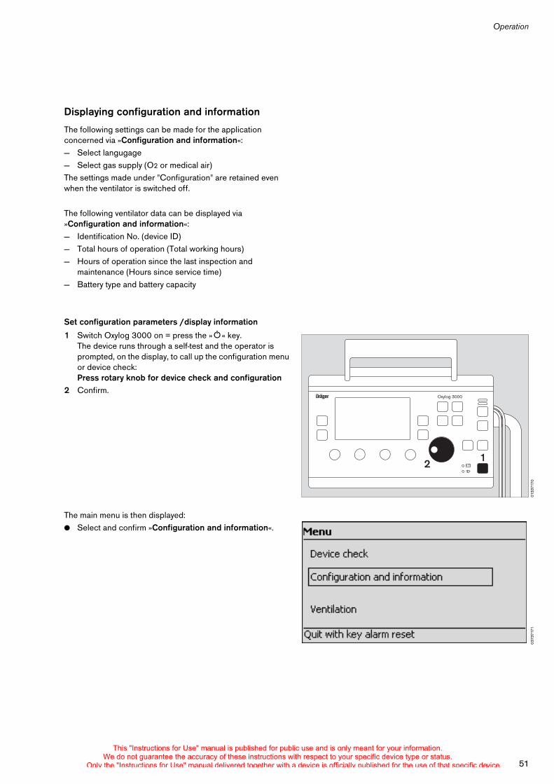
51
Operation
Displaying configuration and information
The following settings can be made for the application concerned via »Configuration and information«:— Select langugage— Select gas supply (O2 or medical air)The settings made under "Configuration" are retained even when the ventilator is switched off.
The following ventilator data can be displayed via »Configuration and information«:— Identification No. (device ID)— Total hours of operation (Total working hours)— Hours of operation since the last inspection and
maintenance (Hours since service time)— Battery type and battery capacity
Set configuration parameters /display information
1 Switch Oxylog 3000 on = press the »O« key.The device runs through a self-test and the operator is prompted, on the display, to call up the configuration menu or device check:Press rotary knob for device check and configuration
2 Confirm.
The main menu is then displayed:! Select and confirm »Configuration and information«.
0133
7170
Oxylog 3000
2 1
0373
7171
This "Instructions for Use" manual is published for public use and is only meant for your information.We do not guarantee the accuracy of these instructions with respect to your specific device type or status.
Only the "Instructions for Use" manual delivered together with a device is officially published for the use of that specific device.
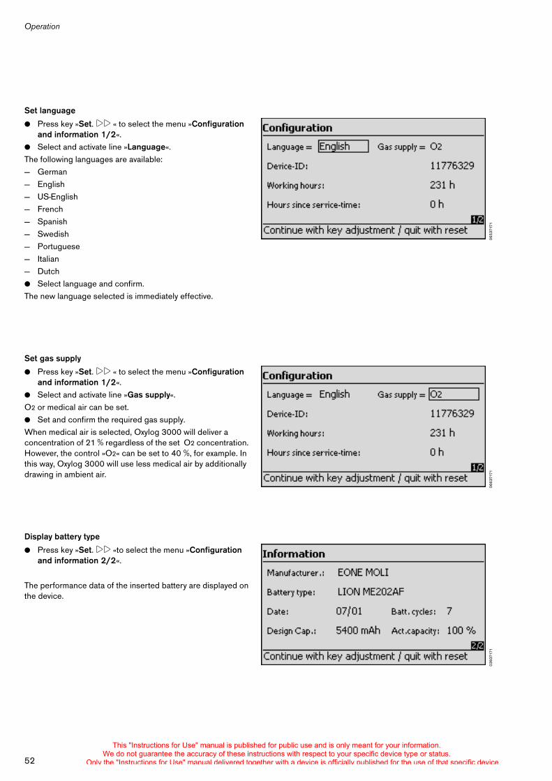
Operation
52
Set language
! Press key »Set. !! « to select the menu »Configuration and information 1/2«.
! Select and activate line »Language«.The following languages are available:— German— English— US-English— French— Spanish— Swedish— Portuguese— Italian— Dutch! Select language and confirm.The new language selected is immediately effective.
Set gas supply
! Press key »Set. !! « to select the menu »Configuration and information 1/2«.
! Select and activate line »Gas supply«.O2 or medical air can be set.! Set and confirm the required gas supply.When medical air is selected, Oxylog 3000 will deliver a concentration of 21 % regardless of the set O2 concentration. However, the control »O2« can be set to 40 %, for example. In this way, Oxylog 3000 will use less medical air by additionally drawing in ambient air.
Display battery type
! Press key »Set. !! «to select the menu »Configuration and information 2/2«.
The performance data of the inserted battery are displayed on the device.
0653
7171
0663
7171
0393
7171
This "Instructions for Use" manual is published for public use and is only meant for your information.We do not guarantee the accuracy of these instructions with respect to your specific device type or status.
Only the "Instructions for Use" manual delivered together with a device is officially published for the use of that specific device.
Fault – Cause – Remedy
53
Fault – cause – remedy . . . . . . . . . . . . . . . . . . . . . . . . . . . . . . . . . . . . . . . . . . . . . . . . 54
Messages in the Alarms window . . . . . . . . . . . . . . . . . . . . . . . . . . . . . . . . . . . . . . 54
Messages in the information window . . . . . . . . . . . . . . . . . . . . . . . . . . . . . . . . . . . 56
Fault – Cause – Remedy
This "Instructions for Use" manual is published for public use and is only meant for your information.We do not guarantee the accuracy of these instructions with respect to your specific device type or status.
Only the "Instructions for Use" manual delivered together with a device is officially published for the use of that specific device.
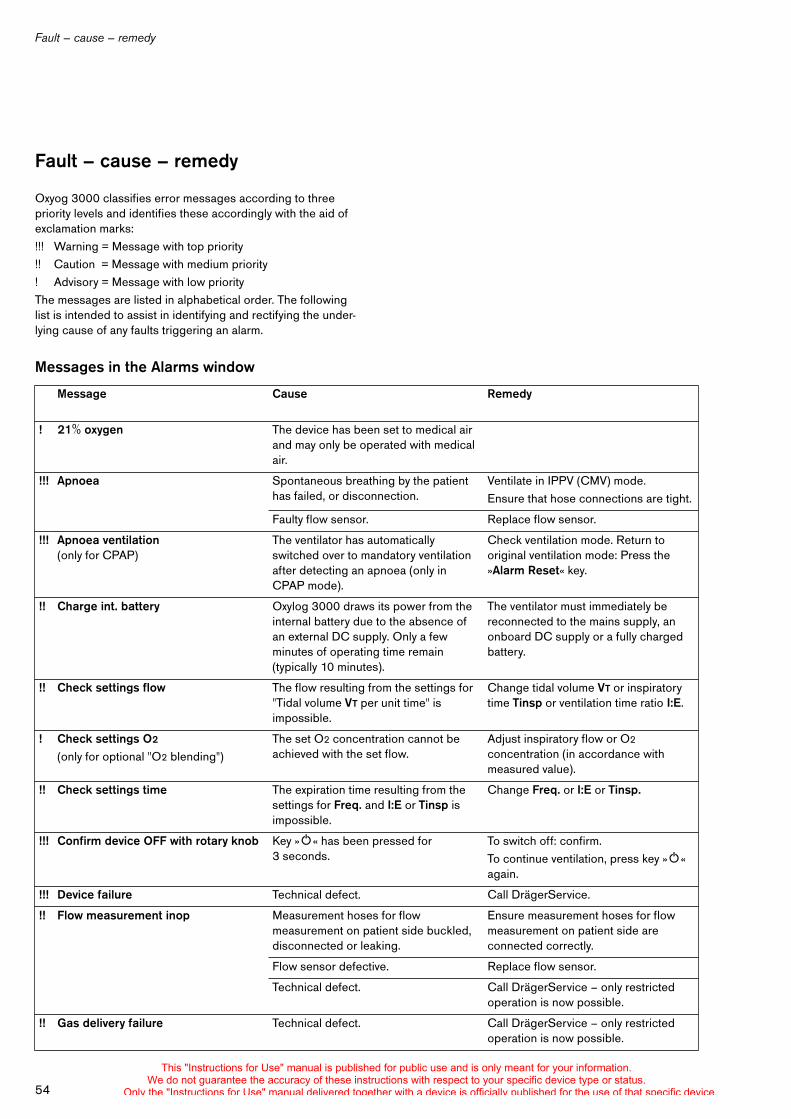
Fault – cause – remedy
54
Fault – cause – remedy
Oxyog 3000 classifies error messages according to three priority levels and identifies these accordingly with the aid of exclamation marks:!!! Warning = Message with top priority!! Caution = Message with medium priority! Advisory = Message with low priorityThe messages are listed in alphabetical order. The following list is intended to assist in identifying and rectifying the under-lying cause of any faults triggering an alarm.
Messages in the Alarms window
Message Cause Remedy
! 21% oxygen The device has been set to medical air and may only be operated with medical air.
!!! Apnoea Spontaneous breathing by the patient has failed, or disconnection.
Ventilate in IPPV (CMV) mode.Ensure that hose connections are tight.
Faulty flow sensor. Replace flow sensor.
!!! Apnoea ventilation(only for CPAP)
The ventilator has automatically switched over to mandatory ventilation after detecting an apnoea (only in CPAP mode).
Check ventilation mode. Return to original ventilation mode: Press the »Alarm Reset« key.
!! Charge int. battery Oxylog 3000 draws its power from the internal battery due to the absence of an external DC supply. Only a few minutes of operating time remain (typically 10 minutes).
The ventilator must immediately be reconnected to the mains supply, an onboard DC supply or a fully charged battery.
!! Check settings flow The flow resulting from the settings for "Tidal volume VT per unit time" is impossible.
Change tidal volume VT or inspiratory time Tinsp or ventilation time ratio I:E.
! Check settings O2
(only for optional "O2 blending")The set O2 concentration cannot be achieved with the set flow.
Adjust inspiratory flow or O2 concentration (in accordance with measured value).
!! Check settings time The expiration time resulting from the settings for Freq. and I:E or Tinsp is impossible.
Change Freq. or I:E or Tinsp.
!!! Confirm device OFF with rotary knob Key »O« has been pressed for 3 seconds.
To switch off: confirm.To continue ventilation, press key »O« again.
!!! Device failure Technical defect. Call DrägerService.
!! Flow measurement inop Measurement hoses for flow measurement on patient side buckled, disconnected or leaking.
Ensure measurement hoses for flow measurement on patient side are connected correctly.
Flow sensor defective. Replace flow sensor.
Technical defect. Call DrägerService – only restricted operation is now possible.
!! Gas delivery failure Technical defect. Call DrägerService – only restricted operation is now possible.
This "Instructions for Use" manual is published for public use and is only meant for your information.We do not guarantee the accuracy of these instructions with respect to your specific device type or status.
Only the "Instructions for Use" manual delivered together with a device is officially published for the use of that specific device.
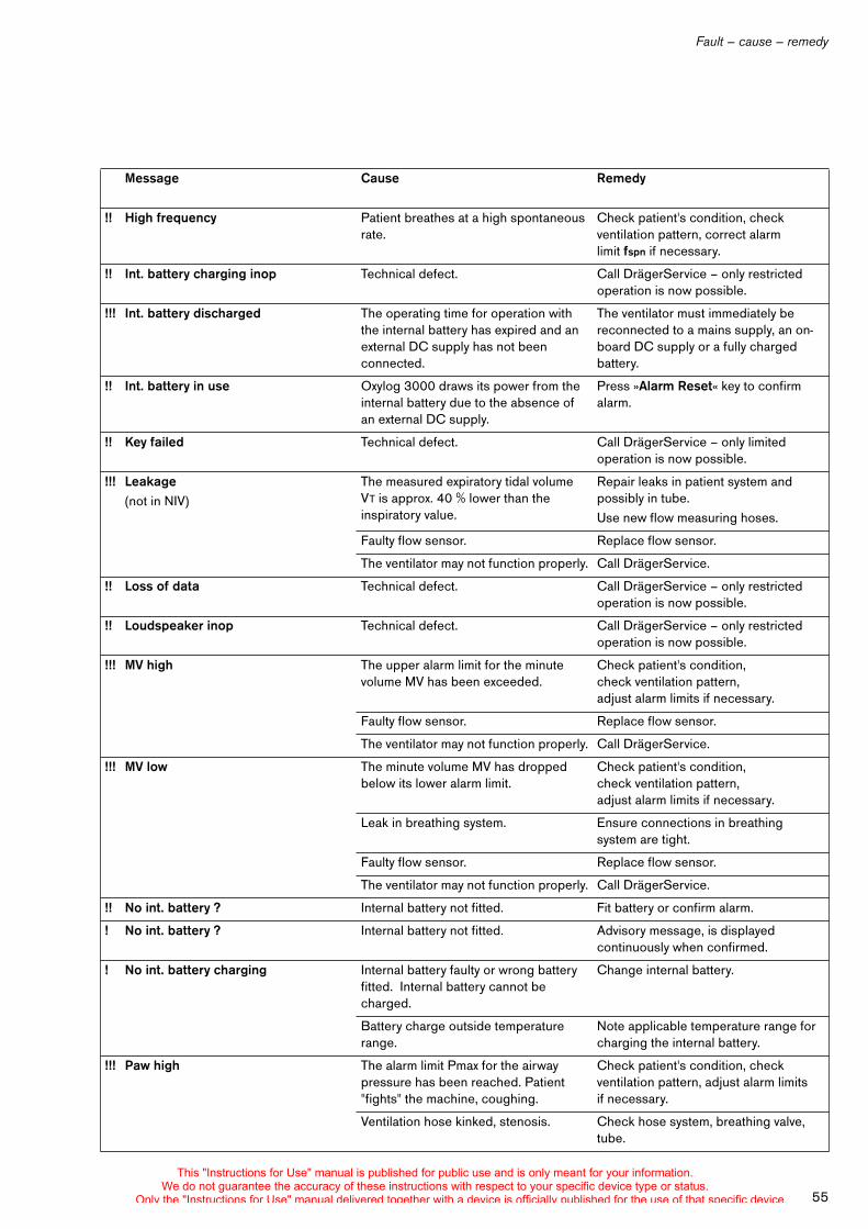
55
Fault – cause – remedy
!! High frequency Patient breathes at a high spontaneous rate.
Check patient's condition, check ventilation pattern, correct alarm limit fspn if necessary.
!! Int. battery charging inop Technical defect. Call DrägerService – only restricted operation is now possible.
!!! Int. battery discharged The operating time for operation with the internal battery has expired and an external DC supply has not been connected.
The ventilator must immediately be reconnected to a mains supply, an on-board DC supply or a fully charged battery.
!! Int. battery in use Oxylog 3000 draws its power from the internal battery due to the absence of an external DC supply.
Press »Alarm Reset« key to confirm alarm.
!! Key failed Technical defect. Call DrägerService – only limited operation is now possible.
!!! Leakage(not in NIV)
The measured expiratory tidal volume VT is approx. 40 % lower than the inspiratory value.
Repair leaks in patient system and possibly in tube.Use new flow measuring hoses.
Faulty flow sensor. Replace flow sensor.
The ventilator may not function properly. Call DrägerService.
!! Loss of data Technical defect. Call DrägerService – only restricted operation is now possible.
!! Loudspeaker inop Technical defect. Call DrägerService – only restricted operation is now possible.
!!! MV high The upper alarm limit for the minute volume MV has been exceeded.
Check patient's condition, check ventilation pattern, adjust alarm limits if necessary.
Faulty flow sensor. Replace flow sensor.
The ventilator may not function properly. Call DrägerService.
!!! MV low The minute volume MV has dropped below its lower alarm limit.
Check patient's condition, check ventilation pattern, adjust alarm limits if necessary.
Leak in breathing system. Ensure connections in breathing system are tight.
Faulty flow sensor. Replace flow sensor.
The ventilator may not function properly. Call DrägerService.
!! No int. battery ? Internal battery not fitted. Fit battery or confirm alarm.
! No int. battery ? Internal battery not fitted. Advisory message, is displayed continuously when confirmed.
! No int. battery charging Internal battery faulty or wrong battery fitted. Internal battery cannot be charged.
Change internal battery.
Battery charge outside temperature range.
Note applicable temperature range for charging the internal battery.
!!! Paw high The alarm limit Pmax for the airway pressure has been reached. Patient "fights" the machine, coughing.
Check patient's condition, check ventilation pattern, adjust alarm limits if necessary.
Ventilation hose kinked, stenosis. Check hose system, breathing valve, tube.
Message Cause Remedy
This "Instructions for Use" manual is published for public use and is only meant for your information.We do not guarantee the accuracy of these instructions with respect to your specific device type or status.
Only the "Instructions for Use" manual delivered together with a device is officially published for the use of that specific device.
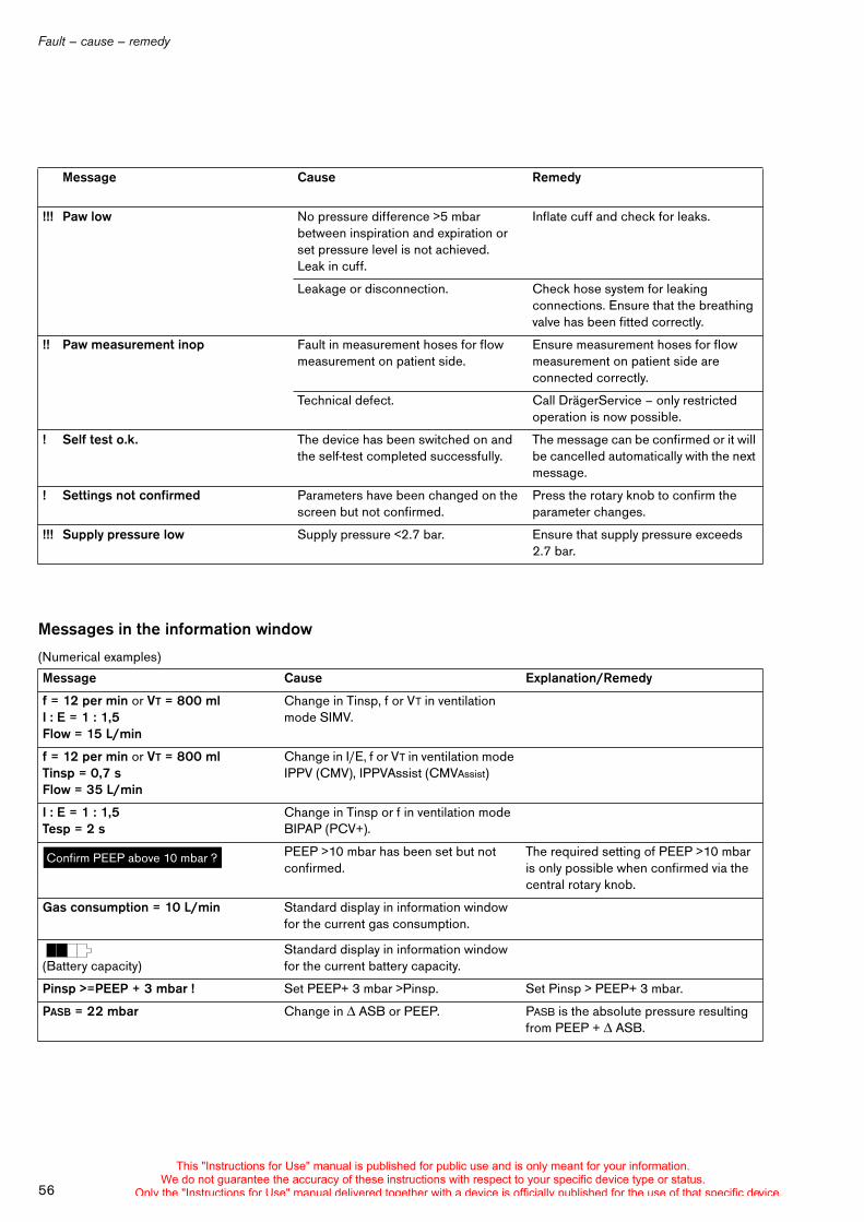
Fault – cause – remedy
56
Messages in the information window
(Numerical examples)
!!! Paw low No pressure difference >5 mbar between inspiration and expiration or set pressure level is not achieved. Leak in cuff.
Inflate cuff and check for leaks.
Leakage or disconnection. Check hose system for leaking connections. Ensure that the breathing valve has been fitted correctly.
!! Paw measurement inop Fault in measurement hoses for flow measurement on patient side.
Ensure measurement hoses for flow measurement on patient side are connected correctly.
Technical defect. Call DrägerService – only restricted operation is now possible.
! Self test o.k. The device has been switched on and the self-test completed successfully.
The message can be confirmed or it will be cancelled automatically with the next message.
! Settings not confirmed Parameters have been changed on the screen but not confirmed.
Press the rotary knob to confirm the parameter changes.
!!! Supply pressure low Supply pressure <2.7 bar. Ensure that supply pressure exceeds 2.7 bar.
Message Cause Explanation/Remedy
f = 12 per min or VT = 800 mlI : E = 1 : 1,5Flow = 15 L/min
Change in Tinsp, f or VT in ventilation mode SIMV.
f = 12 per min or VT = 800 mlTinsp = 0,7 sFlow = 35 L/min
Change in I/E, f or VT in ventilation mode IPPV (CMV), IPPVAssist (CMVAssist)
I : E = 1 : 1,5Tesp = 2 s
Change in Tinsp or f in ventilation mode BIPAP (PCV+).
PEEP >10 mbar has been set but not confirmed.
The required setting of PEEP >10 mbar is only possible when confirmed via the central rotary knob.
Gas consumption = 10 L/min Standard display in information window for the current gas consumption.
(Battery capacity)Standard display in information window for the current battery capacity.
Pinsp >=PEEP + 3 mbar ! Set PEEP+ 3 mbar >Pinsp. Set Pinsp > PEEP+ 3 mbar.
PASB = 22 mbar Change in ASB or PEEP. PASB is the absolute pressure resulting from PEEP + ASB.
Message Cause Remedy
Confirm PEEP above 10 mbar ?
This "Instructions for Use" manual is published for public use and is only meant for your information.We do not guarantee the accuracy of these instructions with respect to your specific device type or status.
Only the "Instructions for Use" manual delivered together with a device is officially published for the use of that specific device.
Care
57
Care . . . . . . . . . . . . . . . . . . . . . . . . . . . . . . . . . . . . . . . . . . . . . . . . . . . . . . . . . . . . . . . . . 58
Disassemble reusable ventilation set . . . . . . . . . . . . . . . . . . . . . . . . . . . . . . . . . . . 58
Remove disposable hose set . . . . . . . . . . . . . . . . . . . . . . . . . . . . . . . . . . . . . . . . . 60
Cleaning and disinfecting . . . . . . . . . . . . . . . . . . . . . . . . . . . . . . . . . . . . . . . . . . . . 60
Sterilising reusable hose sets . . . . . . . . . . . . . . . . . . . . . . . . . . . . . . . . . . . . . . . . . 62
Maintenance intervals . . . . . . . . . . . . . . . . . . . . . . . . . . . . . . . . . . . . . . . . . . . . . . . 62
Batteries . . . . . . . . . . . . . . . . . . . . . . . . . . . . . . . . . . . . . . . . . . . . . . . . . . . . . . . . . . . 63
Device disposal . . . . . . . . . . . . . . . . . . . . . . . . . . . . . . . . . . . . . . . . . . . . . . . . . . . . . 63
Care
This "Instructions for Use" manual is published for public use and is only meant for your information.We do not guarantee the accuracy of these instructions with respect to your specific device type or status.
Only the "Instructions for Use" manual delivered together with a device is officially published for the use of that specific device.
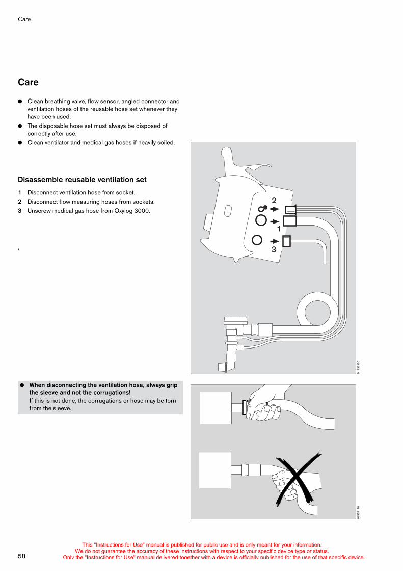
Care
58
Care
! Clean breathing valve, flow sensor, angled connector and ventilation hoses of the reusable hose set whenever they have been used.
! The disposable hose set must always be disposed of correctly after use.
! Clean ventilator and medical gas hoses if heavily soiled.
Disassemble reusable ventilation set
1 Disconnect ventilation hose from socket.2 Disconnect flow measuring hoses from sockets.3 Unscrew medical gas hose from Oxylog 3000.
,
! When disconnecting the ventilation hose, always grip the sleeve and not the corrugations!If this is not done, the corrugations or hose may be torn from the sleeve.
0143
7170
2
1
3
0153
7170
This "Instructions for Use" manual is published for public use and is only meant for your information.We do not guarantee the accuracy of these instructions with respect to your specific device type or status.
Only the "Instructions for Use" manual delivered together with a device is officially published for the use of that specific device.
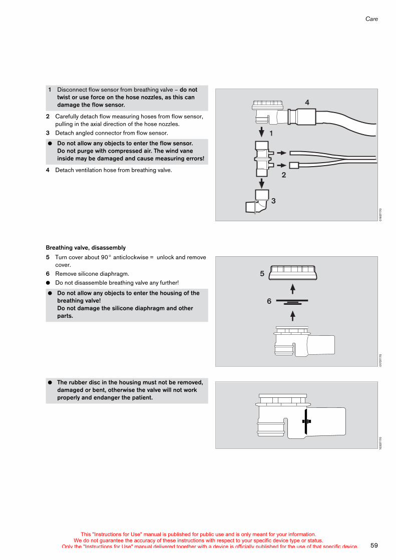
59
Care
2 Carefully detach flow measuring hoses from flow sensor, pulling in the axial direction of the hose nozzles.
3 Detach angled connector from flow sensor.
4 Detach ventilation hose from breathing valve.
Breathing valve, disassembly
5 Turn cover about 90° anticlockwise = unlock and remove cover.
6 Remove silicone diaphragm.! Do not disassemble breathing valve any further!
1 Disconnect flow sensor from breathing valve – do not twist or use force on the hose nozzles, as this can damage the flow sensor.
! Do not allow any objects to enter the flow sensor.Do not purge with compressed air. The wind vane inside may be damaged and cause measuring errors!
! Do not allow any objects to enter the housing of the breathing valve!Do not damage the silicone diaphragm and other parts.
! The rubber disc in the housing must not be removed, damaged or bent, otherwise the valve will not work properly and endanger the patient.
0163
7170
2
1
3
4
0173
7170
5
6
1033
7170
This "Instructions for Use" manual is published for public use and is only meant for your information.We do not guarantee the accuracy of these instructions with respect to your specific device type or status.
Only the "Instructions for Use" manual delivered together with a device is officially published for the use of that specific device.
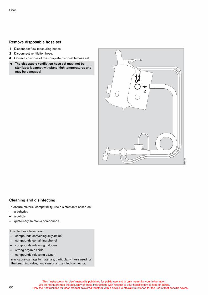
Care
60
Remove disposable hose set
1 Disconnect flow measuring hoses.2 Disconnect ventilation hose.! Correctly dispose of the complete disposable hose set.
Cleaning and disinfecting
To ensure material compatibility, use disinfectants based on:— aldehydes — alcohols — quaternary ammonia compounds.
! The disposable ventilation hose set must not be sterilized: it cannot withstand high temperatures and may be damaged!
Disinfectants based on: — compounds containing alkylamine— compounds containing phenol— compounds releasing halogen— strong organic acids— compounds releasing oxygen may cause damage to materials, particularly those used for the breathing valve, flow sensor and angled connector.
0763
7170
1
2
This "Instructions for Use" manual is published for public use and is only meant for your information.We do not guarantee the accuracy of these instructions with respect to your specific device type or status.
Only the "Instructions for Use" manual delivered together with a device is officially published for the use of that specific device.
61
Care
Users in the Federal Republic of Germany are recommended to use only disinfectants on the current DGHM list (DGHM: German Society for Hygiene and Microbiology).The following disinfectants on the DGHM list are recommended:— Dismozon pur — Incidur — Sekusept Powder — TrichlorolThe DGHM list (published by: mhp-Verlag, Wiesbaden) also specifies the active ingredient in each disinfectant. Disinfectants based on the active ingredients specified above are recommended for users in those countries in which the DGHM list is not available.
Disinfecting by wiping
Ventilator and medical gas hose: ! Follow the manufacturer's instructions. Remove heavy
soiling with a disposable cloth first.
Bath disinfecting
Disassembled parts of the breathing valve, flow sensor, ventilation hose and flow measuring hoses:
! Do not allow any liquid to enter the ventilator or medical gas hose! Risk of malfunctions.
! Follow the manufacturer's instructions. Agitate parts thoroughly in the solution.Do not clean with a hard brush!
! Do not allow any objects to enter the breathing valve or flow sensor!Risk of malfunctions.
! Rinse parts thoroughly with distilled water. Disinfectant residues can cause the rubber disc to become jammed in the breathing valve!
! Allow to dry completely. The breathing valve and flow measuring hoses may not function correctly if water remains in these parts!
This "Instructions for Use" manual is published for public use and is only meant for your information.We do not guarantee the accuracy of these instructions with respect to your specific device type or status.
Only the "Instructions for Use" manual delivered together with a device is officially published for the use of that specific device.
Care
62
Sterilising reusable hose sets
Disassemble the breathing valve, flow sensor and angled connector. Dismantle the breathing valve.The disassembled parts of the breathing valve, the flow sensor, the angled connector, the flow measuring hoses and the ventilation hose ! can be sterilized in hot steam at 134 °C in accordance with
EN 285 (Sterilization – Steam sterilization – Large-scale sterilization) for at least 3 minutes.
Sterilization for up to 18 minutes is permissible, but will shorten the service life of the hose set.
After care
! Reassemble, page 16.! Connect to power supply, page 19 and gas supply,
page 22.! Check readiness for operation, page 26.
Note service life of the hose set
The parts of the breathing valve, the flow sensor, the angled connector, the flow measuring hoses and the ventilation hose are resistant to the recommended disinfectants and to the temperatures occurring during sterilisation.However, every disinfection and sterilisation cycle also means wear for the parts concerned. For this reason, the parts must be examined for cracks and permanent deformation after the care procedure.! Damaged or deformed parts must be replaced.
Maintenance intervals
! Must be carried out by trained service personnel ! Ventilator and parts must be disinfected and cleaned
before starting any maintenance procedures, as well as before returning machine or parts for repairs!
Dust filter, must be replaced after 2 yearscan be treated as household waste
internal battery replace after 2 years orwhen the battery no longer remains
charged for the specified operating time (battery operating time
see page 90). Disposal as special waste.
Device inspection every 2 yearsand maintenance
This "Instructions for Use" manual is published for public use and is only meant for your information.We do not guarantee the accuracy of these instructions with respect to your specific device type or status.
Only the "Instructions for Use" manual delivered together with a device is officially published for the use of that specific device.
63
Care
Batteries
Batteries are special waste: ! They must be disposed of in accordance with the local
waste disposal regulations.
Device disposal
— at the end of its useful life.
! Oxylog 3000 must be disposed of correctly in consultation with the relevant waste disposal companies.
! The statutory regulations must be observed.
Batteries:! Do not burn, risk of explosion!! Do not open forcibly, risk of caustic burns!
This "Instructions for Use" manual is published for public use and is only meant for your information.We do not guarantee the accuracy of these instructions with respect to your specific device type or status.
Only the "Instructions for Use" manual delivered together with a device is officially published for the use of that specific device.

64
This "Instructions for Use" manual is published for public use and is only meant for your information.We do not guarantee the accuracy of these instructions with respect to your specific device type or status.
Only the "Instructions for Use" manual delivered together with a device is officially published for the use of that specific device.
What's what
65
What's what . . . . . . . . . . . . . . . . . . . . . . . . . . . . . . . . . . . . . . . . . . . . . . . . . . . . . . . . . . . 66
Front panel – standard version . . . . . . . . . . . . . . . . . . . . . . . . . . . . . . . . . . . . . . . . 66
Front panel with all options . . . . . . . . . . . . . . . . . . . . . . . . . . . . . . . . . . . . . . . . . . . 67
Side view, right . . . . . . . . . . . . . . . . . . . . . . . . . . . . . . . . . . . . . . . . . . . . . . . . . . . . . 68
Rear view . . . . . . . . . . . . . . . . . . . . . . . . . . . . . . . . . . . . . . . . . . . . . . . . . . . . . . . . . . 68
Reusable hose set . . . . . . . . . . . . . . . . . . . . . . . . . . . . . . . . . . . . . . . . . . . . . . . . . . 68
Disposable hose set . . . . . . . . . . . . . . . . . . . . . . . . . . . . . . . . . . . . . . . . . . . . . . . . . 69
What's what
This "Instructions for Use" manual is published for public use and is only meant for your information.We do not guarantee the accuracy of these instructions with respect to your specific device type or status.
Only the "Instructions for Use" manual delivered together with a device is officially published for the use of that specific device.
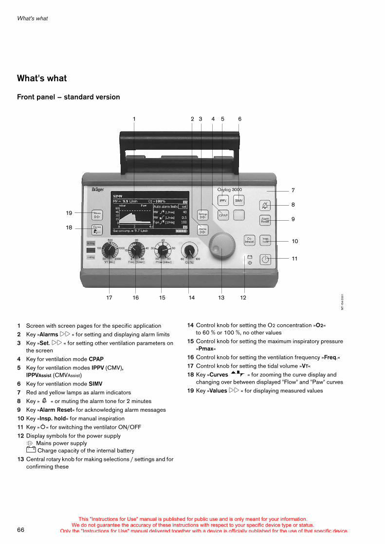
66
What's what
14 Control knob for setting the O2 concentration »O2« to 60 % or 100 %, no other values
15 Control knob for setting the maximum inspiratory pressure »Pmax«
16 Control knob for setting the ventilation frequency »Freq.«17 Control knob for setting the tidal volume »VT«18 Key »Curves « for zooming the curve display and
changing over between displayed "Flow" and "Paw" curves 19 Key »Values !! « for displaying measured values
What's what
Front panel – standard version
1 Screen with screen pages for the specific application2 Key »Alarms !! « for setting and displaying alarm limits3 Key »Set. !! « for setting other ventilation parameters on
the screen4 Key for ventilation mode CPAP5 Key for ventilation modes IPPV (CMV),
IPPVAssist (CMVAssist)6 Key for ventilation mode SIMV7 Red and yellow lamps as alarm indicators8 Key » g « or muting the alarm tone for 2 minutes9 Key »Alarm Reset« for acknowledging alarm messages10 Key »Insp. hold« for manual inspiration11 Key »O« for switching the ventilator ON/OFF12 Display symbols for the power supplyN Mains power supplyJ Charge capacity of the internal battery
13 Central rotary knob for making selections / settings and for confirming these
MT-
154-
2001
1 2 3 4 5 6
19
18
7
8
9
10
11
17 16 15 14 13 12
This "Instructions for Use" manual is published for public use and is only meant for your information.We do not guarantee the accuracy of these instructions with respect to your specific device type or status.
Only the "Instructions for Use" manual delivered together with a device is officially published for the use of that specific device.
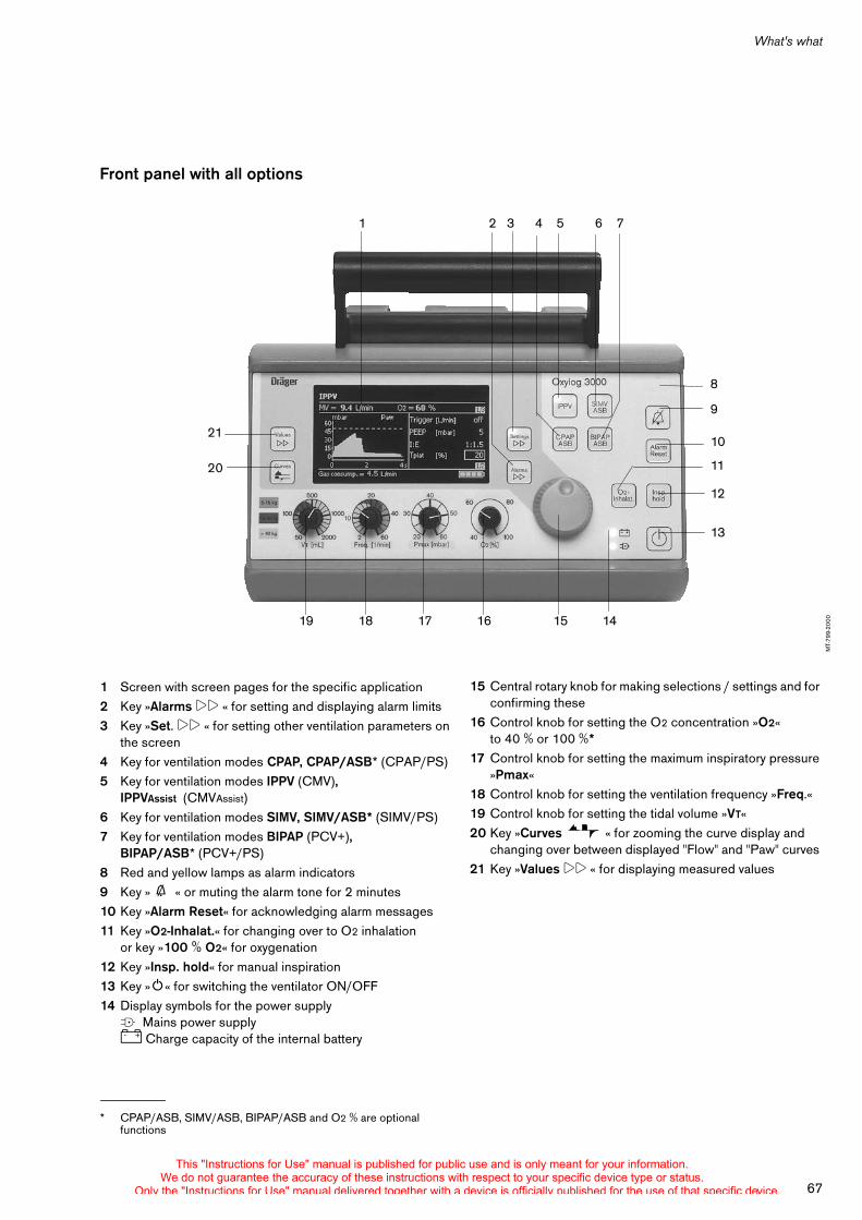
67
What's what
Front panel with all options
1 Screen with screen pages for the specific application2 Key »Alarms !! « for setting and displaying alarm limits3 Key »Set. !! « for setting other ventilation parameters on
the screen4 Key for ventilation modes CPAP, CPAP/ASB* (CPAP/PS)5 Key for ventilation modes IPPV (CMV),
IPPVAssist (CMVAssist)6 Key for ventilation modes SIMV, SIMV/ASB* (SIMV/PS)7 Key for ventilation modes BIPAP (PCV+),
BIPAP/ASB* (PCV+/PS)8 Red and yellow lamps as alarm indicators9 Key » g « or muting the alarm tone for 2 minutes10 Key »Alarm Reset« for acknowledging alarm messages11 Key »O2-Inhalat.« for changing over to O2 inhalation
or key »100 % O2« for oxygenation12 Key »Insp. hold« for manual inspiration13 Key »O« for switching the ventilator ON/OFF14 Display symbols for the power supplyN Mains power supplyJ Charge capacity of the internal battery
* CPAP/ASB, SIMV/ASB, BIPAP/ASB and O2 % are optional functions
MT-
799-
2000 19 18 17 16 15 14
1 2 3 4 5 6 7
21
20
8
9
10
11
12
13
15 Central rotary knob for making selections / settings and for confirming these
16 Control knob for setting the O2 concentration »O2« to 40 % or 100 %*
17 Control knob for setting the maximum inspiratory pressure »Pmax«
18 Control knob for setting the ventilation frequency »Freq.«19 Control knob for setting the tidal volume »VT«20 Key »Curves « for zooming the curve display and
changing over between displayed "Flow" and "Paw" curves 21 Key »Values !! « for displaying measured values
This "Instructions for Use" manual is published for public use and is only meant for your information.We do not guarantee the accuracy of these instructions with respect to your specific device type or status.
Only the "Instructions for Use" manual delivered together with a device is officially published for the use of that specific device.
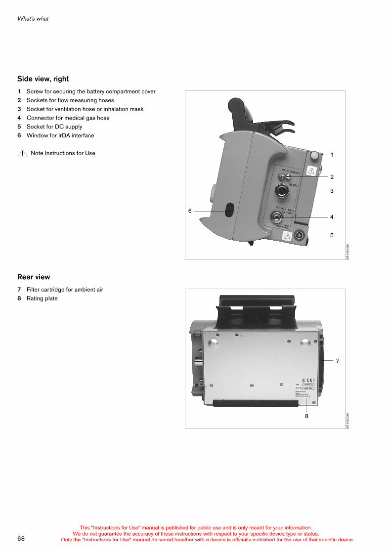
What's what
68
Side view, right
1 Screw for securing the battery compartment cover2 Sockets for flow measuring hoses3 Socket for ventilation hose or inhalation mask4 Connector for medical gas hose5 Socket for DC supply6 Window for IrDA interface
Note Instructions for Use
Rear view
7 Filter cartridge for ambient air8 Rating plate
MT-
156-
2001
6
1
2
5
3
4
MT-
158-
2001
7
8
This "Instructions for Use" manual is published for public use and is only meant for your information.We do not guarantee the accuracy of these instructions with respect to your specific device type or status.
Only the "Instructions for Use" manual delivered together with a device is officially published for the use of that specific device.
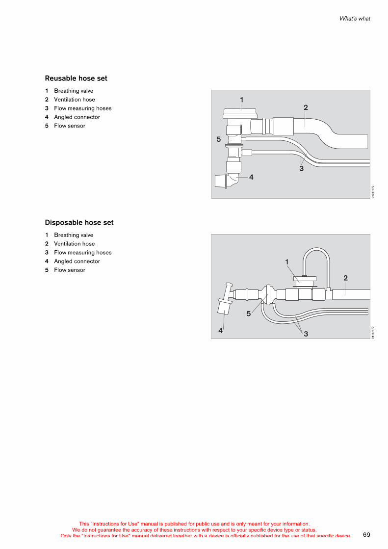
69
What's what
Reusable hose set
1 Breathing valve2 Ventilation hose3 Flow measuring hoses4 Angled connector5 Flow sensor
Disposable hose set
1 Breathing valve2 Ventilation hose3 Flow measuring hoses4 Angled connector5 Flow sensor
0493
7170
12
5
34
0813
7170
1
2
3
5
4
This "Instructions for Use" manual is published for public use and is only meant for your information.We do not guarantee the accuracy of these instructions with respect to your specific device type or status.
Only the "Instructions for Use" manual delivered together with a device is officially published for the use of that specific device.

70
This "Instructions for Use" manual is published for public use and is only meant for your information.We do not guarantee the accuracy of these instructions with respect to your specific device type or status.
Only the "Instructions for Use" manual delivered together with a device is officially published for the use of that specific device.

Accessories
71
Carrier System 3000 (optional) . . . . . . . . . . . . . . . . . . . . . . . . . . . . . . . . . . . . . . . . . 72
Onboard Equipment Holder (optional) . . . . . . . . . . . . . . . . . . . . . . . . . . . . . . . . . . . 74
Accessories
This "Instructions for Use" manual is published for public use and is only meant for your information.We do not guarantee the accuracy of these instructions with respect to your specific device type or status.
Only the "Instructions for Use" manual delivered together with a device is officially published for the use of that specific device.
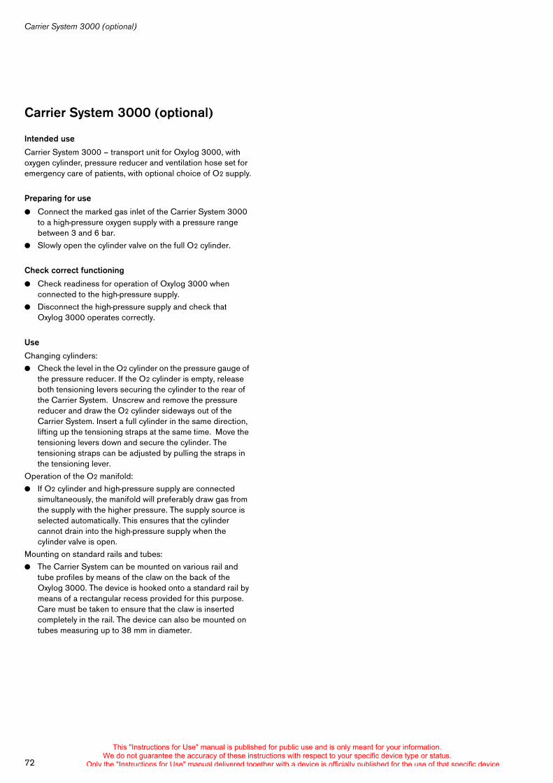
Carrier System 3000 (optional)
72
Carrier System 3000 (optional)
Intended use
Carrier System 3000 – transport unit for Oxylog 3000, with oxygen cylinder, pressure reducer and ventilation hose set for emergency care of patients, with optional choice of O2 supply.
Preparing for use
! Connect the marked gas inlet of the Carrier System 3000 to a high-pressure oxygen supply with a pressure range between 3 and 6 bar.
! Slowly open the cylinder valve on the full O2 cylinder.
Check correct functioning
! Check readiness for operation of Oxylog 3000 when connected to the high-pressure supply.
! Disconnect the high-pressure supply and check that Oxylog 3000 operates correctly.
Use
Changing cylinders:! Check the level in the O2 cylinder on the pressure gauge of
the pressure reducer. If the O2 cylinder is empty, release both tensioning levers securing the cylinder to the rear of the Carrier System. Unscrew and remove the pressure reducer and draw the O2 cylinder sideways out of the Carrier System. Insert a full cylinder in the same direction, lifting up the tensioning straps at the same time. Move the tensioning levers down and secure the cylinder. The tensioning straps can be adjusted by pulling the straps in the tensioning lever.
Operation of the O2 manifold:! If O2 cylinder and high-pressure supply are connected
simultaneously, the manifold will preferably draw gas from the supply with the higher pressure. The supply source is selected automatically. This ensures that the cylinder cannot drain into the high-pressure supply when the cylinder valve is open.
Mounting on standard rails and tubes:! The Carrier System can be mounted on various rail and
tube profiles by means of the claw on the back of the Oxylog 3000. The device is hooked onto a standard rail by means of a rectangular recess provided for this purpose. Care must be taken to ensure that the claw is inserted completely in the rail. The device can also be mounted on tubes measuring up to 38 mm in diameter.
This "Instructions for Use" manual is published for public use and is only meant for your information.We do not guarantee the accuracy of these instructions with respect to your specific device type or status.
Only the "Instructions for Use" manual delivered together with a device is officially published for the use of that specific device.
73
Carrier System 3000 (optional)
After use
! Disconnect the high-pressure supply and close the valve on the O2 cylinder.
Technical data
When mounted on a tube or rail, the Carrier System is only held by its own weight. The ventilator must be secured additionally, particularly when it is being transported. Vibrations may cause the ventilator to drop and injure the patient or user.
Operating temperature –20 oC to +70 oCStorage temperature –20 oC to +80 oCWidth x Height x Depth 450 x 400 x 240 mmWeight with maximum equipment and 2.0 litre cylinder (glass-fibre-reinforced plastic material) 14.5 kgVariable cylinder length 300 to 530 mmPermissible cylinder weight 6.1 kg
This "Instructions for Use" manual is published for public use and is only meant for your information.We do not guarantee the accuracy of these instructions with respect to your specific device type or status.
Only the "Instructions for Use" manual delivered together with a device is officially published for the use of that specific device.
Onboard Equipment Holder (optional)
74
Onboard Equipment Holder (optional)
Intended use
Onboard Equipment Holder – mounting unit for Oxylog 3000 which can be inserted, locked and subsequently removed by the user and which can be pivoted horizontally. The onboard equipment holder is designed for mounting on the roof or wall of a vehicle.
Preparing for use
! Secure the onboard equipment holder to the wall of the vehicle via the three mounting holes with M5 screw connections provided for this purpose.
! The hose for the high-pressure supply must also be secured to the wall.
Use
Insert Oxylog 3000 in the onboard equipment holder:! Hook the cross-bar of the onboard equipment holder into
the claw recess on Oxylog 3000. Swing the ventilator to the rear about the cross-bar until resistance is felt. Press firmly against the bottom edge of the ventilator control unit to engage it. A distinct click must be heard.
Remove Oxylog 3000 from the onboard equipment holder:! Reach behind the Oxylog 3000 until the release lever of the
onboard equipment holder can be felt and press it firmly forwards with the ball of the hand. The ventilator is released with a distinct click and swings downwards. It can then be removed from the onboard equipment holder by means of its handle.
Turn Oxylog 3000 in the onboard equipment holder:! Hold the sides of the ventilator with both hands and turn it
firmly about its vertical axis. The ventilator can be set to any position.
This "Instructions for Use" manual is published for public use and is only meant for your information.We do not guarantee the accuracy of these instructions with respect to your specific device type or status.
Only the "Instructions for Use" manual delivered together with a device is officially published for the use of that specific device.
Service Mode
75
Service Mode . . . . . . . . . . . . . . . . . . . . . . . . . . . . . . . . . . . . . . . . . . . . . . . . . . . . . . . . . 76
Customer Service Mode . . . . . . . . . . . . . . . . . . . . . . . . . . . . . . . . . . . . . . . . . . . . . 76
Set startup settings . . . . . . . . . . . . . . . . . . . . . . . . . . . . . . . . . . . . . . . . . . . . . . . . . 77
Select hose type . . . . . . . . . . . . . . . . . . . . . . . . . . . . . . . . . . . . . . . . . . . . . . . . . . . . 78
Set date and time . . . . . . . . . . . . . . . . . . . . . . . . . . . . . . . . . . . . . . . . . . . . . . . . . . . 78
Set measured values display window . . . . . . . . . . . . . . . . . . . . . . . . . . . . . . . . . . 79
Enter activation code . . . . . . . . . . . . . . . . . . . . . . . . . . . . . . . . . . . . . . . . . . . . . . . . 79
Test buttons and potentiometer . . . . . . . . . . . . . . . . . . . . . . . . . . . . . . . . . . . . . . . 79
Test loudspeaker, buzzer, LEDs and display . . . . . . . . . . . . . . . . . . . . . . . . . . . . 80
Display accu and supply data . . . . . . . . . . . . . . . . . . . . . . . . . . . . . . . . . . . . . . . . . 80
Display actual technical error . . . . . . . . . . . . . . . . . . . . . . . . . . . . . . . . . . . . . . . . . 80
Display error and info logbook . . . . . . . . . . . . . . . . . . . . . . . . . . . . . . . . . . . . . . . . 81
Display settings logbook . . . . . . . . . . . . . . . . . . . . . . . . . . . . . . . . . . . . . . . . . . . . . 81
Display language text . . . . . . . . . . . . . . . . . . . . . . . . . . . . . . . . . . . . . . . . . . . . . . . . 81
Exit service mode . . . . . . . . . . . . . . . . . . . . . . . . . . . . . . . . . . . . . . . . . . . . . . . . . . . 82
Service Mode
This "Instructions for Use" manual is published for public use and is only meant for your information.We do not guarantee the accuracy of these instructions with respect to your specific device type or status.
Only the "Instructions for Use" manual delivered together with a device is officially published for the use of that specific device.
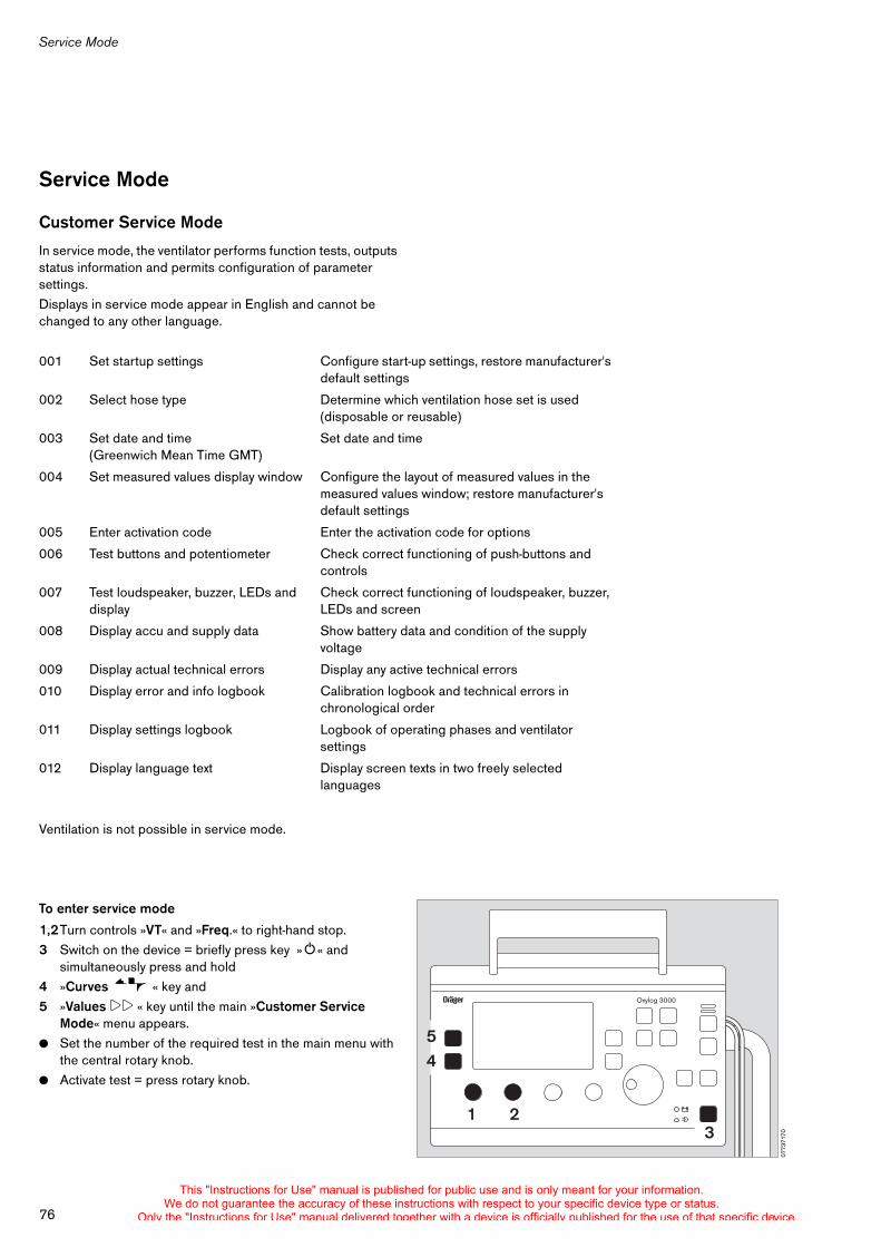
Service Mode
76
Service Mode
Customer Service Mode
In service mode, the ventilator performs function tests, outputs status information and permits configuration of parameter settings.Displays in service mode appear in English and cannot be changed to any other language.
Ventilation is not possible in service mode.
To enter service mode
1,2Turn controls »VT« and »Freq.« to right-hand stop.3 Switch on the device = briefly press key »O« and
simultaneously press and hold4 »Curves « key and 5 »Values !! « key until the main »Customer Service
Mode« menu appears.! Set the number of the required test in the main menu with
the central rotary knob.! Activate test = press rotary knob.
001 Set startup settings Configure start-up settings, restore manufacturer's default settings
002 Select hose type Determine which ventilation hose set is used (disposable or reusable)
003 Set date and time (Greenwich Mean Time GMT)
Set date and time
004 Set measured values display window Configure the layout of measured values in the measured values window; restore manufacturer's default settings
005 Enter activation code Enter the activation code for options
006 Test buttons and potentiometer Check correct functioning of push-buttons and controls
007 Test loudspeaker, buzzer, LEDs and display
Check correct functioning of loudspeaker, buzzer, LEDs and screen
008 Display accu and supply data Show battery data and condition of the supply voltage
009 Display actual technical errors Display any active technical errors
010 Display error and info logbook Calibration logbook and technical errors in chronological order
011 Display settings logbook Logbook of operating phases and ventilator settings
012 Display language text Display screen texts in two freely selected languages
0773
7170
Oxylog 3000
1 23
54
This "Instructions for Use" manual is published for public use and is only meant for your information.We do not guarantee the accuracy of these instructions with respect to your specific device type or status.
Only the "Instructions for Use" manual delivered together with a device is officially published for the use of that specific device.
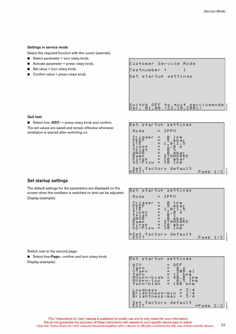
77
Service Mode
Settings in service mode
Select the required function with the cursor (asterisk).! Select parameter = turn rotary knob.! Activate parameter = press rotary knob.! Set value = turn rotary knob.! Confirm value = press rotary knob.
Quit test:
! Select line »EXIT« = press rotary knob and confirm.The set values are saved and remain effective whenever ventilation is started after switching on.
Set startup settings
The default settings for the parameters are displayed on the screen when the ventilator is switched on and can be adjusted.Display (example):
Switch over to the second page:! Select line»Page«, confirm and turn rotary knob.Display (example):
1173
7170
1183
7170
0973
7170
0983
7170
This "Instructions for Use" manual is published for public use and is only meant for your information.We do not guarantee the accuracy of these instructions with respect to your specific device type or status.
Only the "Instructions for Use" manual delivered together with a device is officially published for the use of that specific device.
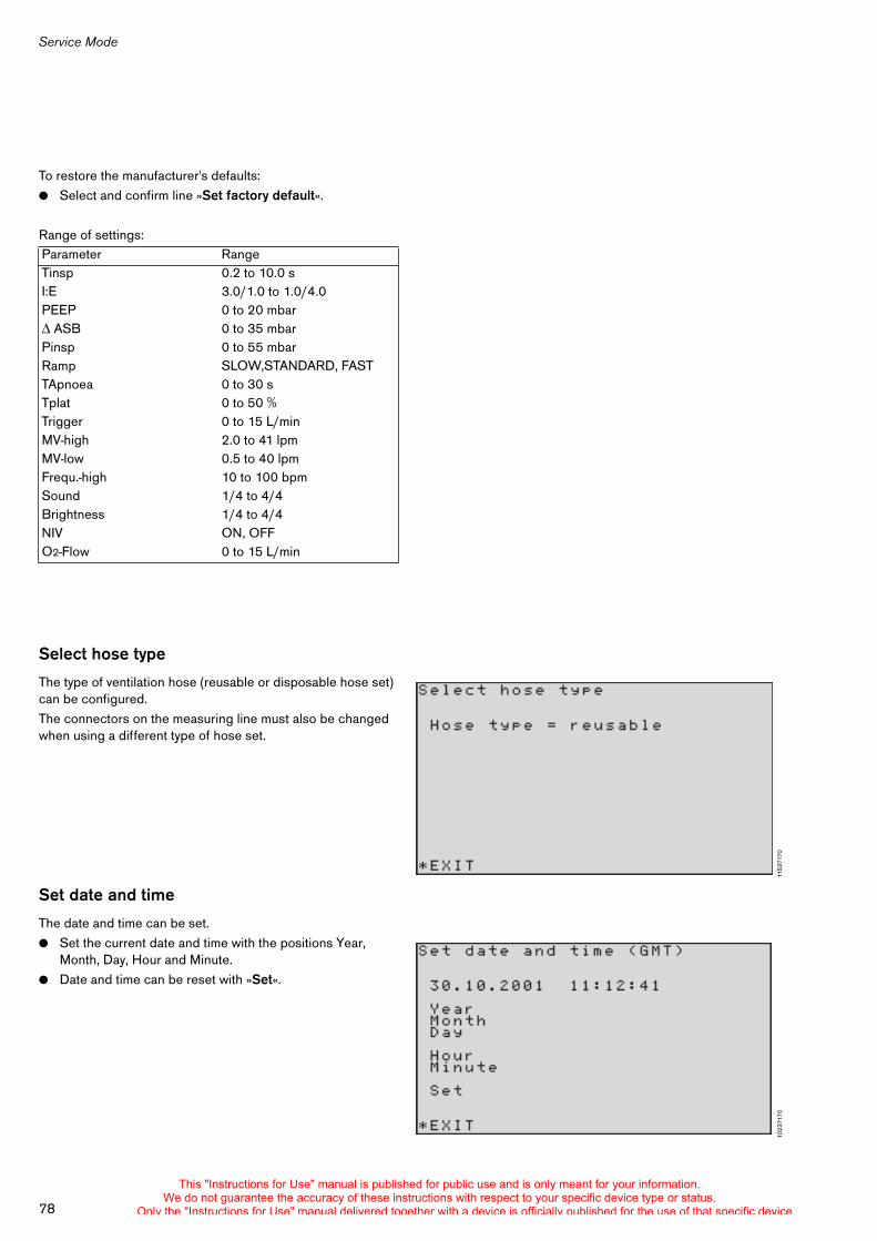
Service Mode
78
To restore the manufacturer's defaults:! Select and confirm line »Set factory default«.
Range of settings:
Select hose type
The type of ventilation hose (reusable or disposable hose set) can be configured.The connectors on the measuring line must also be changed when using a different type of hose set.
Set date and time
The date and time can be set.! Set the current date and time with the positions Year,
Month, Day, Hour and Minute.! Date and time can be reset with »Set«.
Parameter RangeTinsp 0.2 to 10.0 sI:E 3.0/1.0 to 1.0/4.0PEEP 0 to 20 mbar
ASB 0 to 35 mbarPinsp 0 to 55 mbarRamp SLOW,STANDARD, FASTTApnoea 0 to 30 sTplat 0 to 50 %Trigger 0 to 15 L/minMV-high 2.0 to 41 lpmMV-low 0.5 to 40 lpmFrequ.-high 10 to 100 bpmSound 1/4 to 4/4Brightness 1/4 to 4/4NIV ON, OFFO2-Flow 0 to 15 L/min
1153
7170
1023
7170
This "Instructions for Use" manual is published for public use and is only meant for your information.We do not guarantee the accuracy of these instructions with respect to your specific device type or status.
Only the "Instructions for Use" manual delivered together with a device is officially published for the use of that specific device.
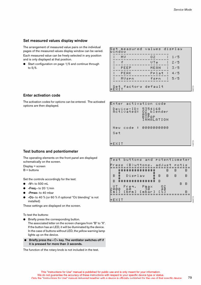
79
Service Mode
Set measured values display window
The arrangement of measured value pairs on the individual pages of the measured values display window can be varied.Each measured value can be freely selected in any position and is only displayed at that position.! Start configuration on page 1/5 and continue through
to 5/5.
Enter activation code
The activation codes for options can be entered. The activated options are then displayed.
Test buttons and potentiometer
The operating elements on the front panel are displayed schematically on the screen.Display = screen B = buttons
Set the controls accordingly for the test:! »VT« to 500 mL! »Freq.« to 20 1/min! »Pmax« to 40 mbar! »O2« to 40 % (or 60 % if optional "O2 blending" is not
installed)These settings are displayed on the screen.
To test the buttons:! Briefly press the corresponding button.
The associated letter on the screen changes from "B" to "X".If the button has an LED, it will be illuminated by the device. In the case of buttons without LED, the yellow warning lamp lights up on the device.
The function of the rotary knob is not included in the test.
! Briefly press the »O« key. The ventilator switches off if it is pressed for more than 3 seconds.
1163
7170
1143
7170
0943
7170
This "Instructions for Use" manual is published for public use and is only meant for your information.We do not guarantee the accuracy of these instructions with respect to your specific device type or status.
Only the "Instructions for Use" manual delivered together with a device is officially published for the use of that specific device.
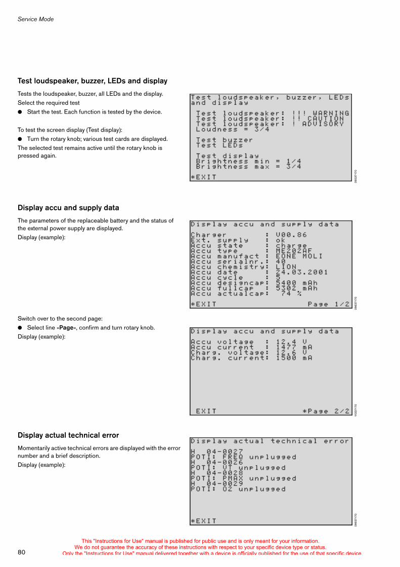
Service Mode
80
Test loudspeaker, buzzer, LEDs and display
Tests the loudspeaker, buzzer, all LEDs and the display.Select the required test! Start the test. Each function is tested by the device.
To test the screen display (Test display):! Turn the rotary knob; various test cards are displayed.The selected test remains active until the rotary knob is pressed again.
Display accu and supply data
The parameters of the replaceable battery and the status of the external power supply are displayed.Display (example):
Switch over to the second page:! Select line »Page«, confirm and turn rotary knob.Display (example):
Display actual technical error
Momentarily active technical errors are displayed with the error number and a brief description.Display (example):
0953
7170
0963
7170
1133
7170
0993
7170
This "Instructions for Use" manual is published for public use and is only meant for your information.We do not guarantee the accuracy of these instructions with respect to your specific device type or status.
Only the "Instructions for Use" manual delivered together with a device is officially published for the use of that specific device.
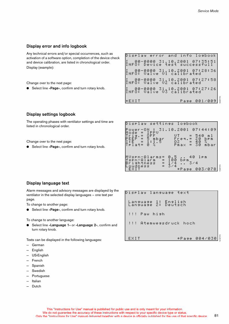
81
Service Mode
Display error and info logbook
Any technical errors and/or special occurrences, such as activation of a software option, completion of the device check and device calibration, are listed in chronological order.Display (example):
Change over to the next page:! Select line »Page«, confirm and turn rotary knob.
Display settings logbook
The operating phases with ventilator settings and time are listed in chronological order.
Change over to the next page:! Select line »Page«, confirm and turn rotary knob.
Display language text
Alarm messages and advisory messages are displayed by the ventilator in the selected display languages – one text per page.To change to another page:! Select line »Page«, confirm and turn rotary knob.
To change to another language:! Select line »Language 1« or »Language 2«, confirm and
turn rotary knob.
Texts can be displayed in the following languages:— German— English— US-English— French— Spanish— Swedish— Portuguese— Italian— Dutch
1003
7170
1123
7170
1013
7170
This "Instructions for Use" manual is published for public use and is only meant for your information.We do not guarantee the accuracy of these instructions with respect to your specific device type or status.
Only the "Instructions for Use" manual delivered together with a device is officially published for the use of that specific device.

Service Mode
82
Exit service mode
! Press key »O« for 3 seconds; its yellow lamp flashes.
To switch ventilation on:! Briefly press key »O«.
To switch off:! Press rotary knob.
This "Instructions for Use" manual is published for public use and is only meant for your information.We do not guarantee the accuracy of these instructions with respect to your specific device type or status.
Only the "Instructions for Use" manual delivered together with a device is officially published for the use of that specific device.

Abbreviations and symbols
83
Abbreviations . . . . . . . . . . . . . . . . . . . . . . . . . . . . . . . . . . . . . . . . . . . . . . . . . . . . . . . . . 84
Symbols . . . . . . . . . . . . . . . . . . . . . . . . . . . . . . . . . . . . . . . . . . . . . . . . . . . . . . . . . . . . . . 85
Abbreviations and symbols
This "Instructions for Use" manual is published for public use and is only meant for your information.We do not guarantee the accuracy of these instructions with respect to your specific device type or status.
Only the "Instructions for Use" manual delivered together with a device is officially published for the use of that specific device.
84
Abbreviations
Abbreviations
Abbreviation Explanation
ASB (PS) Assisted Spontaneous BreathingPressure-assisted spontaneous breathing
BIPAP (PCV+) Biphasic Positive Airway PressureSpontaneous breathing with continuous positive airway pressure and two different pressure levels
BIPAP/ASB (PCV+/PS)
Biphasic Positive Airway PressureAssisted Spontaneous BreathingPressure-controlled ventilation in combination with spontaneous breathing throughout the breathing cycle and with variable pressure support at CPAP level
BTPS Body Temperatur, Pressure, SaturatedMeasured values referred to the conditions of the patient's lung, body temperature 37 oC, ambient pressure, water-vapour-saturated gas
C Compliance
CMV Controlled Mandatory Ventilation
CPAP Continuous Positive Airway Pressure Spontaneous breathing with continuous positive pressure
CPAP/ASB (CPSP/PS)
Continuous Positive Airway Pressure Assisted Spontaneous BreathingSpontaneous breathing at an elevated pressure level
EN 794-3 European standard for medical ventilators, Part 3 "Emergency and transport ventilators"
ASB Set value for pressure support ASB – ASB over PEEP
f Ventilation frequency
fApnoea Frequency of apnoea ventilation
Freq. Ventilation frequency
fspn Spontaneous breathing rate
IPPV (CMV) Intermittent Positive Pressure Ventilation
IPPVAssist
(CMVAssist)Assisted Intermittent Positive Pressure Ventilation
I:E Ratio inspiration time : expiration time
MV Minute volume
MVspn Proportion of the minute volume which is accounted for by spontaneous breathing
NIV Non-invasive ventilation – mask ventilation
O2 Set value for the inspiratory O2 concentration
O2-inhalat. O2 inhalation
Paw Airway pressure
PCV+ Pressure Controlled Ventilation plus
PEEP Positive end expiratory pressure
Pinsp Set value of the upper pressure level in BIPAP
Pmax Maximum airway pressure
Pmean Mean airway pressure
Ppeak Maximum airway pressure
Pplat End inspiratory airway pressure
PS Pressure Support
R Resistance
Ramp Set value for the rise in pressure over time for pressure assistance with ASB
SIMV Synchronized Intermittent Mandatory Ventilation
SIMV/ASB (SIMV/PS)
Synchronized Intermittent Mandatory Ventilation Assisted Spontaneous BreathingVentilation can be supplemented with ASB
TApnoea Apnoea alarm time
Te Expiration time
Tinsp Set inspiration time
Tplat Plateau time
VTApnoea Tidal volume of apnoea ventilation
VT Set tidal volume
VTe Exp. Tidal volume
VTi Insp. Tidal volume
100 % O2 100 % O2 flow
Abbreviation Explanation
This "Instructions for Use" manual is published for public use and is only meant for your information.We do not guarantee the accuracy of these instructions with respect to your specific device type or status.
Only the "Instructions for Use" manual delivered together with a device is officially published for the use of that specific device.
85
Symbols
Symbols
Symbol Explanation
, Inspiration is started and held manually
Display screen window "Settings"
Display screen window "Alarms"
Display screen window "Measured values"
Changeover between flow / pressure curve
Suppress acoustic alarm for 2 minutes
Acknowledge alarms
E Standby/Operation switch
_ Lower and upper alarm limits
> Upper alarm limit only
< Lower alarm limit only
! Advisory message
!! Caution message
!!! Warning
Strictly follow the Instructions for Use!
Protection class B (body)
Protection class BF (body floating)
J DC supply
N AC supply
Battery charge (example: half full)
Settings!!
Alarms!!
Values!!
Curves
AlarmReset
This "Instructions for Use" manual is published for public use and is only meant for your information.We do not guarantee the accuracy of these instructions with respect to your specific device type or status.
Only the "Instructions for Use" manual delivered together with a device is officially published for the use of that specific device.

86
This "Instructions for Use" manual is published for public use and is only meant for your information.We do not guarantee the accuracy of these instructions with respect to your specific device type or status.
Only the "Instructions for Use" manual delivered together with a device is officially published for the use of that specific device.

Technical Data
87
Technical Data . . . . . . . . . . . . . . . . . . . . . . . . . . . . . . . . . . . . . . . . . . . . . . . . . . . . . . . . 88
Technical Data
This "Instructions for Use" manual is published for public use and is only meant for your information.We do not guarantee the accuracy of these instructions with respect to your specific device type or status.
Only the "Instructions for Use" manual delivered together with a device is officially published for the use of that specific device.
Technical Data
88
Technical Data
Ambient conditions During operation
Temperature –20 to 50 oC1)
1) when used with disposable hose set. –10 to 50 oC
Atmospheric pressure 570 to 1200 hPaRel. humidity 5 to 95 %
During storageVentilator without replaceable battery, with reusable ventilation hose setTemperature –40 to 75 oCAtmospheric pressure 570 to 1200 hPaRel. humidity 5 to 95 %
Disposable ventilation hose setTemperature –20 to 70 oCAtmospheric pressure 570 to 1200 hPaRel. humidity 30 to 50 %
Replaceable batteryTemperature –20 to 35 oCAtmospheric pressure 570 to 1200 hPaRel. humidity 5 to 95 %
SettingsVentilation modes IPPV (CMV)/IPPVAssist (CMVAssist),
SIMV, SIMV/ASB (SIMV/PS), BIPAP (PCV+), BIPAP/ASB (PCV+/PS), CPAP, CPAP/ASB (CPAP/PS)
Ventilation frequency Freq. 2 to 60 1/min ±1 1/min (SIMV, BIPAP)5 to 60 1/min ±1 1/min (IPPV, IPPVAssist) 12 to 60 1/min ±1 1/min for apnoea ventilation
Ventilation time ratio I:E (IPPV, IPPVAssist) 1:4 to 3:1Inspiration time Tinsp (SIMV, SIMV/ASB, BIPAP, BIPAP/ASB)
0.2 to 10 s
Tidal volume VT 0.05 to 2.0 L, BTPS2)
2) BTPSBody Temperature, Pressure, Saturated.Measured values referred to the conditions of the patient's lungs, body temperature 37 oC, ambient pressure, water-vapour-saturated gas.
Accuracy ±15 % of set value or ±25 mL,whichever is greater.
Inspiratory pressure Pinsp PEEP+3 mbar to 55 mbar3)
3) 1 mbar = 100 Pa
O2 concentration 40 to 100 Vol.%4)
4) with optional O2 blending
Accuracy ±10 Vol.%The setting depends on the inspiratory flow5)
5) see O2 concentration, page 42
Positive end expiratory pressure PEEP 0 to 20 mbar ±2 mbar, no negative pressureTrigger sensitivity (flow trigger) 3 to 15 L/min
This "Instructions for Use" manual is published for public use and is only meant for your information.We do not guarantee the accuracy of these instructions with respect to your specific device type or status.
Only the "Instructions for Use" manual delivered together with a device is officially published for the use of that specific device.
89
Technical Data
Pressure support ASB 0 to 35 mbar (relative to PEEP) ±2 mbarRise time for pressure support slow, standard, fast
Performance dataControl principle time-cycled, volume-constant, pressure-controlledMax. inspiratory flow 100 L/min1)
1) At service pressures >3.5 barThe maximum inspiratory flow is reduced to 80 L/min at service pressures <3.5 bar
Device compliancewith 1.5 m ventilation hose 1 mL/mbarwith 3 m ventilation hose 2 mL/mbar
Inspiration resistance 4 mbar at 60 L/minExpiration resistance 4 mbar at 60 L/minDead space incl. flow sensor approx. 28 mL (reusable hose set)
approx. 32.5 mL (disposable hose set)
Supplementary functionsDemand valve Opens the breathing system upon failure of the gas supply,
permits spontaneous breathing with ambient airRelief valve Opens the breathing system at approx. 80 mbar
Max. permissible differential pressure for flow measurement ±4 mbar Resistance of flow sensor 3 mbar at 100 L/min (reusable hose set)
2.5 mbar at 100 L/min (disposable hose set)Patient connection 22 mm ISO conical connector
Measured value displayAirway pressure measurement
Range 0 to 99 mbarResolution 1 mbarAccuracy ±2 mbar
Max. airway pressure PpeakPos. end expiratory pressure PEEPMean airway pressure PmeanPlateau pressure Pplat
Flow measurementMinute volume MV
Range 0 to 99 L/min, BTPSResolution 0.1 L/minAccuracy ±15 % of measured value, but at least ±1 L/min
Tidal volume VTe
Range 0 to 5000 mL, BTPSResolution 1 mLAccuracy ±15 % of measured value
This "Instructions for Use" manual is published for public use and is only meant for your information.We do not guarantee the accuracy of these instructions with respect to your specific device type or status.
Only the "Instructions for Use" manual delivered together with a device is officially published for the use of that specific device.
Technical Data
90
Frequency measurementRange 0 to 99 /minResolution 1 /minAccuracy ±1 /min
Curve displayAirway pressure Paw (t) –10 to 100 mbarFlow (t) –120 to 120 L/min
MonitoringExpiratory minute volume MVAlarm, upper alarm limit when the upper alarm limit has been exceeded
Range of settings 41 to 2 L/minAlarm, lower alarm limit when the level drops below the lower alarm limit
Range of settings 0.5 to 40 L/min
Airway pressure PawAlarm, upper alarm limit when value "Pmax" is exceeded
Range of settings 20 to 60 mbarAlarm, lower alarm limit When pressure difference between inspiratory and
expiratory sides is less than 5 mbaror if the set pressure level is not attained.
Apnoea alarm time TApnoea
Alarm when respiratory activity is no longer detectedRange of settings 15 to 60 s, can be set in 1 s increments
Operating dataPower supplyPower supply
Input voltage Oxylog 3000 19 V ±0.5 V DCWith DC/DC converter 12 V / 24V / 28 V DC
Current consumptionWith battery charge max. 3.8 A, typically 2.1 AOperating time with fully charged internal batterywithout mains supply for "typical" ventilation
Approx. 4 hours
Operating time with fully charged nickel metal hydride battery, without mains supply for "typical" ventilation
Approx. 3 hours
Battery charge The device switches over to floating operation when the battery is fully charged.
Battery types Nickel metal hydride batteryLithium ion battery
This "Instructions for Use" manual is published for public use and is only meant for your information.We do not guarantee the accuracy of these instructions with respect to your specific device type or status.
Only the "Instructions for Use" manual delivered together with a device is officially published for the use of that specific device.
91
Technical Data
Charging times The specified charging times apply when recharging the battery fully after it has been exhausted.
Nickel Metal Hybrid battery Approx. 4 hoursLithium ion battery Approx. 5 hours
Permissible ambient temperature during charging 0 oC to 35 oC
Indication of battery capacity in 25 % increments
Accuracy of the capacity indication The indicated capacity is determined by the battery itself. The accuracy depends on the type and manufacturer and may deteriorate with frequent partial discharge and during operation in extreme temperatures. The internal battery is only reconditioned after being discharged completely and recharged at room temperature 25 oC.The criteria for the warnings "!!! Int. battery discharged" and "!! Charge int. battery" are therefore based on measurement of the battery voltage. The capacity indicated at this moment may differ from the actual capacity of the internal battery.
Battery storage time The internal battery must always be removed from Oxylog 3000 for storage and recharged completely after 12 months at the latest (e.g. in the external Oxylog 3000 battery charging station)
AC/DC power packTemperature range –20 oC to 50 oCProtection class to EN 60601 Class I Input 100 to 240 V~/ 50 to 60 Hz / 1.5 AOutput 19 V ±0.5 V /2.1 A, max. 3.8 AInternal fuse 3.15 A slow-blow
DC/DC converterTemperature range –20 oC to 50 oCInput 10 to 32 V DC / 8 AOutput 19 V ±0.5 V / 2.1 A, max. 3.8 AInternal fuse 10 A slow-blow
Gas supply From a pipeline system or from a medical gas cylinder
O2 service pressure 3 bar –10 % to 6 bar at 100 L/minSupply gas Medical oxygen or medical airO2 inlet connection either:
DIN to DIN 13252,orNIST1) to EN 739,orDISS2) to CGA V5-1989,orN-F3) 590-116/1987.The gas must be dry and free of oil and dust.
1) NIST = Non Interchangeable Screw Thread Connection2) DISS = Diameter Index Safety Systems3) N-F = French standard
This "Instructions for Use" manual is published for public use and is only meant for your information.We do not guarantee the accuracy of these instructions with respect to your specific device type or status.
Only the "Instructions for Use" manual delivered together with a device is officially published for the use of that specific device.
Technical Data
92
Gas cylinders and pressure reducers must comply with national regulations and be officially approved.
Pressure reducer must have a vent valve on the output side to limit the delivery pressure to approx. 10 bar in the event of a fault.
Gas consumption for internal control 0.1 to 0.5 L/minAccuracy of gas consumption indication ±0.5 L/min
Noise pressure <45 dB (A) for typical ventilation at a distance of 1 m
Dimensions (W x H x D)Basic unit 285 x 184 x 175 mm (without handle)AC/DC power pack 158 x 60 x 117 mmDC/DC converter 162 x 42 x 69 mm
WeightBasic unit with internal battery Approx. 4.9 kgAC/DC power pack Approx. 0.8 kgDC/DC converter Approx. 0.4 kg
Electromagnetic compatibility EMC tested to EN 60601-1-2 and EN 794-3 (36.101) 10 V/m
Airworthiness (vibration) In accordance with RTCA DO–160D
Mechanical strength In accordance with MIL STD 810 E
Classificationaccording to Directive 93/42/EEC Appendix IX
Class IIb
UMDNS-CodeUniversal Medical Device Nomenclature System
18 – 098
Interface IrDA Infrared RS232 interface
Protection class, ventilation hose sets (disposable or reusable)
Type BF (body floating)
This "Instructions for Use" manual is published for public use and is only meant for your information.We do not guarantee the accuracy of these instructions with respect to your specific device type or status.
Only the "Instructions for Use" manual delivered together with a device is officially published for the use of that specific device.
93
Technical Data
Materials usedHousing, Oxylog 3000 Impact-proof acrylonitrile butadiene styrene (ABS)Housing, AC/DC power pack Impact-proof acrylonitrile butadiene styrene (ABS)Housing, DC/DC converter Impact-proof acrylonitrile butadiene styrene (ABS)Touch sensitive keypad on ventilator Polyester film
Reusable ventilation hose set Ventilation hose, flow measuring hoses Silicone rubberFlow sensor housing, breathing valve Polysulphone (PSU)Vane in flow sensor Stainless steelDiaphragms in breathing valve Silicone rubber
Disposable ventilation hose setVentilation hose Polyethylene (PE)Non-return valve Synthetic resinBreathing valve Polyethylene (PE)Flow sensor housing Polymethyl methacrylate (PMMA)Film in flow sensor PolyesterAdapter Silicone rubberPatient connection Polypropylene (PP)
DisplayTechnology Electro-luminescence (EL)Pixels 240 x 128Visible area 108 x 56 mm
This "Instructions for Use" manual is published for public use and is only meant for your information.We do not guarantee the accuracy of these instructions with respect to your specific device type or status.
Only the "Instructions for Use" manual delivered together with a device is officially published for the use of that specific device.

94
This "Instructions for Use" manual is published for public use and is only meant for your information.We do not guarantee the accuracy of these instructions with respect to your specific device type or status.
Only the "Instructions for Use" manual delivered together with a device is officially published for the use of that specific device.
Description
95
Description . . . . . . . . . . . . . . . . . . . . . . . . . . . . . . . . . . . . . . . . . . . . . . . . . . . . . . . . . . . 96
Ventilation modes . . . . . . . . . . . . . . . . . . . . . . . . . . . . . . . . . . . . . . . . . . . . . . . . . . . 96
Volume-controlled ventilation . . . . . . . . . . . . . . . . . . . . . . . . . . . . . . . . . . . . . . . . . 96
IPPV (CMV) . . . . . . . . . . . . . . . . . . . . . . . . . . . . . . . . . . . . . . . . . . . . . . . . . . . . . . . . 96
IPPVAssist (CMVAssist) . . . . . . . . . . . . . . . . . . . . . . . . . . . . . . . . . . . . . . . . . . . . . 96
SIMV . . . . . . . . . . . . . . . . . . . . . . . . . . . . . . . . . . . . . . . . . . . . . . . . . . . . . . . . . . . . . . 97
ASB (PS) . . . . . . . . . . . . . . . . . . . . . . . . . . . . . . . . . . . . . . . . . . . . . . . . . . . . . . . . . . 98
BIPAP (PCV+) . . . . . . . . . . . . . . . . . . . . . . . . . . . . . . . . . . . . . . . . . . . . . . . . . . . . . . 99
Functional description . . . . . . . . . . . . . . . . . . . . . . . . . . . . . . . . . . . . . . . . . . . . . . 101
Description
This "Instructions for Use" manual is published for public use and is only meant for your information.We do not guarantee the accuracy of these instructions with respect to your specific device type or status.
Only the "Instructions for Use" manual delivered together with a device is officially published for the use of that specific device.
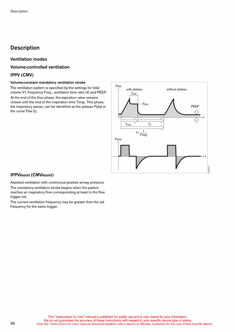
Description
96
Description
Ventilation modes
Volume-controlled ventilation
IPPV (CMV)
Volume-constant mandatory ventilation strokeThe ventilation pattern is specified by the settings for tidal volume VT, frequency Freq., ventilation time ratio I:E and PEEP.At the end of the flow phase, the expiration valve remains closed until the end of the inspiration time Tinsp. This phase, the inspiratory pause, can be identified as the plateau Pplat in the curve Paw (t).
IPPVAssist (CMVAssist)
Assisted ventilation with continuous positive airway pressure.The mandatory ventilation stroke begins when the patient reaches an inspiratory flow corresponding at least to the flow trigger set.The current ventilation frequency may be greater than the set frequency for the same trigger.
0273
7171
Paw
Flow
Tinsp Te
T=
Pplat
1
t
t
PEEP
without plateauwith plateau
Freq.
Tplat
This "Instructions for Use" manual is published for public use and is only meant for your information.We do not guarantee the accuracy of these instructions with respect to your specific device type or status.
Only the "Instructions for Use" manual delivered together with a device is officially published for the use of that specific device.
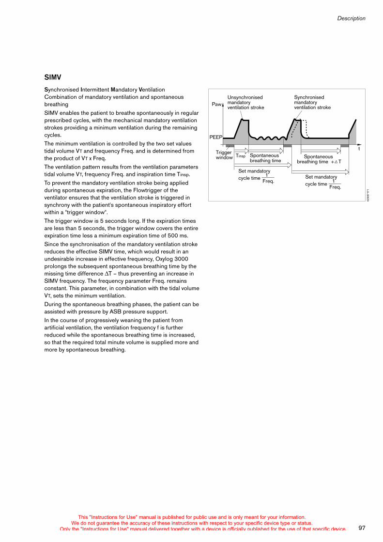
97
Description
SIMV
Synchronised Intermittent Mandatory Ventilation Combination of mandatory ventilation and spontaneous breathingSIMV enables the patient to breathe spontaneously in regular prescribed cycles, with the mechanical mandatory ventilation strokes providing a minimum ventilation during the remaining cycles.The minimum ventilation is controlled by the two set values tidal volume VT and frequency Freq. and is determined from the product of VT x Freq.The ventilation pattern results from the ventilation parameters tidal volume VT, frequency Freq. and inspiration time Tinsp.To prevent the mandatory ventilation stroke being applied during spontaneous expiration, the Flowtrigger of the ventilator ensures that the ventilation stroke is triggered in synchrony with the patient's spontaneous inspiratory effort within a "trigger window".The trigger window is 5 seconds long. If the expiration times are less than 5 seconds, the trigger window covers the entire expiration time less a minimum expiration time of 500 ms.Since the synchronisation of the mandatory ventilation stroke reduces the effective SIMV time, which would result in an undesirable increase in effective frequency, Oxylog 3000 prolongs the subsequent spontaneous breathing time by the missing time difference T – thus preventing an increase in SIMV frequency. The frequency parameter Freq. remains constant. This parameter, in combination with the tidal volume VT, sets the minimum ventilation.During the spontaneous breathing phases, the patient can be assisted with pressure by ASB pressure support.In the course of progressively weaning the patient from artificial ventilation, the ventilation frequency f is further reduced while the spontaneous breathing time is increased, so that the required total minute volume is supplied more and more by spontaneous breathing.
0293
7171
Paw
PEEP
tSpontaneous breathing time
Spontaneous breathing time + T
Trigger window
Synchronised mandatory ventilation stroke
Unsynchronised mandatory ventilation stroke
Tinsp
Freq.1
Set mandatory cycle time
Freq.1
Set mandatory cycle time
This "Instructions for Use" manual is published for public use and is only meant for your information.We do not guarantee the accuracy of these instructions with respect to your specific device type or status.
Only the "Instructions for Use" manual delivered together with a device is officially published for the use of that specific device.
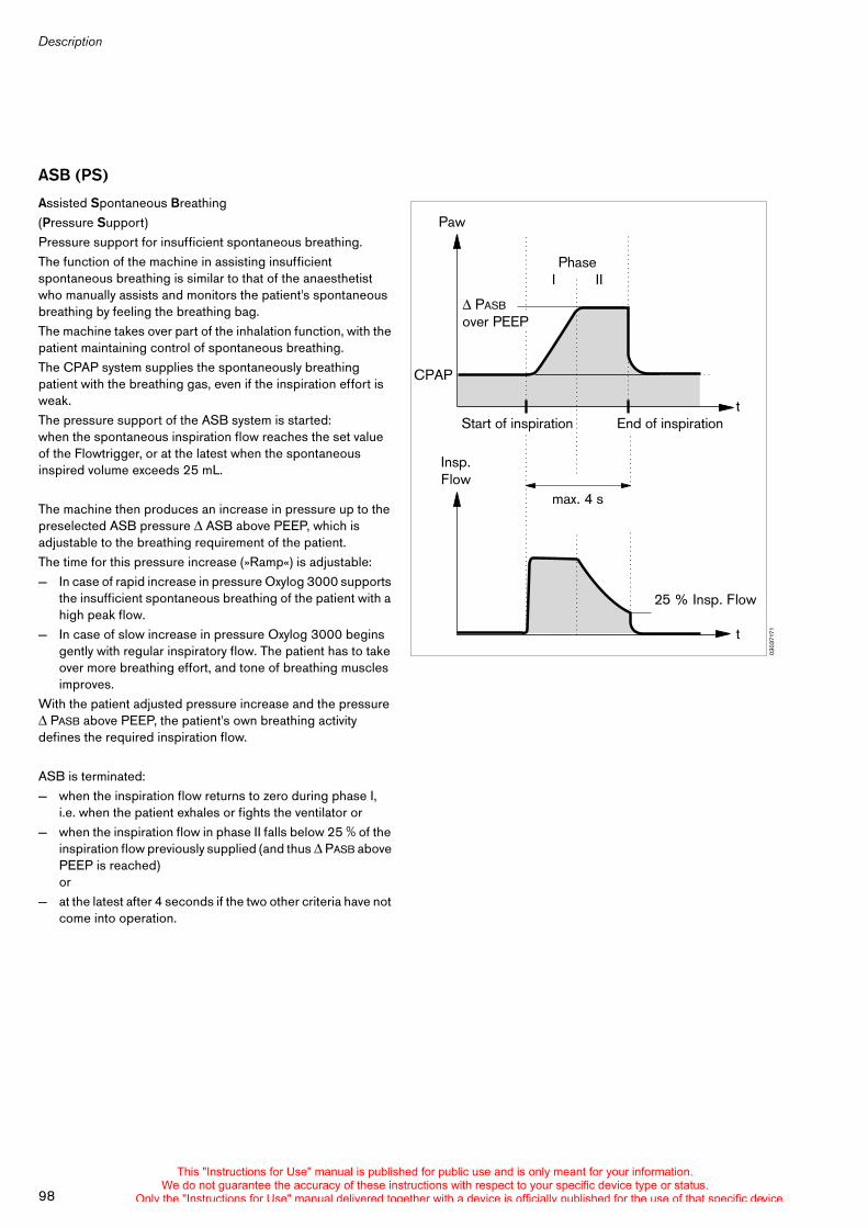
Description
98
ASB (PS)
Assisted Spontaneous Breathing(Pressure Support)Pressure support for insufficient spontaneous breathing.The function of the machine in assisting insufficient spontaneous breathing is similar to that of the anaesthetist who manually assists and monitors the patient's spontaneous breathing by feeling the breathing bag.The machine takes over part of the inhalation function, with the patient maintaining control of spontaneous breathing.The CPAP system supplies the spontaneously breathing patient with the breathing gas, even if the inspiration effort is weak.The pressure support of the ASB system is started: when the spontaneous inspiration flow reaches the set value of the Flowtrigger, or at the latest when the spontaneous inspired volume exceeds 25 mL.
The machine then produces an increase in pressure up to the preselected ASB pressure ASB above PEEP, which is adjustable to the breathing requirement of the patient.The time for this pressure increase (»Ramp«) is adjustable:— In case of rapid increase in pressure Oxylog 3000 supports
the insufficient spontaneous breathing of the patient with a high peak flow.
— In case of slow increase in pressure Oxylog 3000 begins gently with regular inspiratory flow. The patient has to take over more breathing effort, and tone of breathing muscles improves.
With the patient adjusted pressure increase and the pressure PASB above PEEP, the patient's own breathing activity
defines the required inspiration flow.
ASB is terminated: — when the inspiration flow returns to zero during phase I,
i.e. when the patient exhales or fights the ventilator or— when the inspiration flow in phase II falls below 25 % of the
inspiration flow previously supplied (and thus PASB above PEEP is reached)or
— at the latest after 4 seconds if the two other criteria have not come into operation.
0303
7171
PhaseI II
Paw
Insp.Flow
t
t
CPAP
Start of inspiration
max. 4 s
End of inspiration
25 % Insp. Flow
PASB
over PEEP
This "Instructions for Use" manual is published for public use and is only meant for your information.We do not guarantee the accuracy of these instructions with respect to your specific device type or status.
Only the "Instructions for Use" manual delivered together with a device is officially published for the use of that specific device.
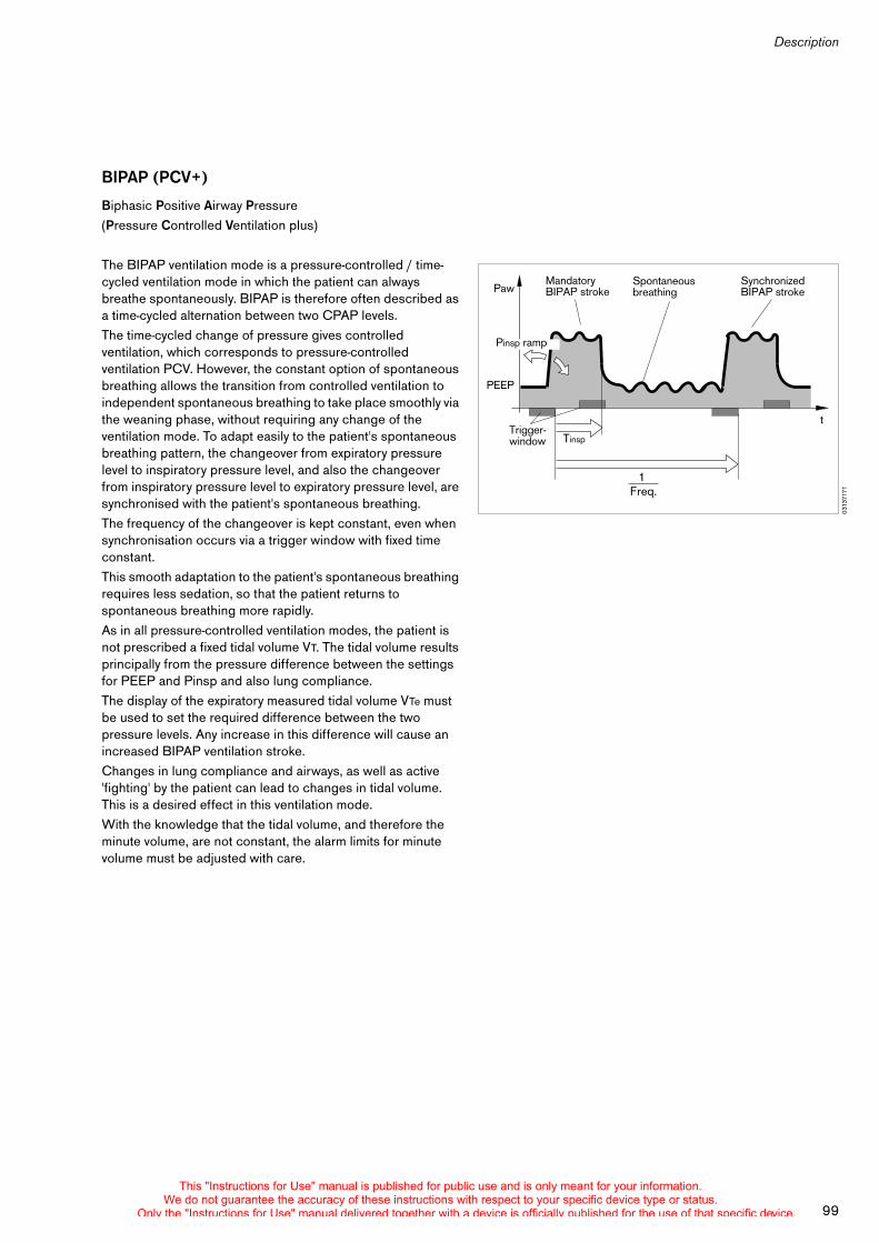
99
Description
BIPAP (PCV+)
Biphasic Positive Airway Pressure(Pressure Controlled Ventilation plus)
The BIPAP ventilation mode is a pressure-controlled / time-cycled ventilation mode in which the patient can always breathe spontaneously. BIPAP is therefore often described as a time-cycled alternation between two CPAP levels.The time-cycled change of pressure gives controlled ventilation, which corresponds to pressure-controlled ventilation PCV. However, the constant option of spontaneous breathing allows the transition from controlled ventilation to independent spontaneous breathing to take place smoothly via the weaning phase, without requiring any change of the ventilation mode. To adapt easily to the patient's spontaneous breathing pattern, the changeover from expiratory pressure level to inspiratory pressure level, and also the changeover from inspiratory pressure level to expiratory pressure level, are synchronised with the patient's spontaneous breathing.The frequency of the changeover is kept constant, even when synchronisation occurs via a trigger window with fixed time constant.This smooth adaptation to the patient's spontaneous breathing requires less sedation, so that the patient returns to spontaneous breathing more rapidly.As in all pressure-controlled ventilation modes, the patient is not prescribed a fixed tidal volume VT. The tidal volume results principally from the pressure difference between the settings for PEEP and Pinsp and also lung compliance.The display of the expiratory measured tidal volume VTe must be used to set the required difference between the two pressure levels. Any increase in this difference will cause an increased BIPAP ventilation stroke.Changes in lung compliance and airways, as well as active 'fighting' by the patient can lead to changes in tidal volume. This is a desired effect in this ventilation mode.With the knowledge that the tidal volume, and therefore the minute volume, are not constant, the alarm limits for minute volume must be adjusted with care.
0313
7171
Paw
PEEP
tTrigger-window
Spontaneous breathing
Mandatory BIPAP stroke
Synchronized BIPAP stroke
Tinsp
Freq.1
Pinsp ramp
This "Instructions for Use" manual is published for public use and is only meant for your information.We do not guarantee the accuracy of these instructions with respect to your specific device type or status.
Only the "Instructions for Use" manual delivered together with a device is officially published for the use of that specific device.
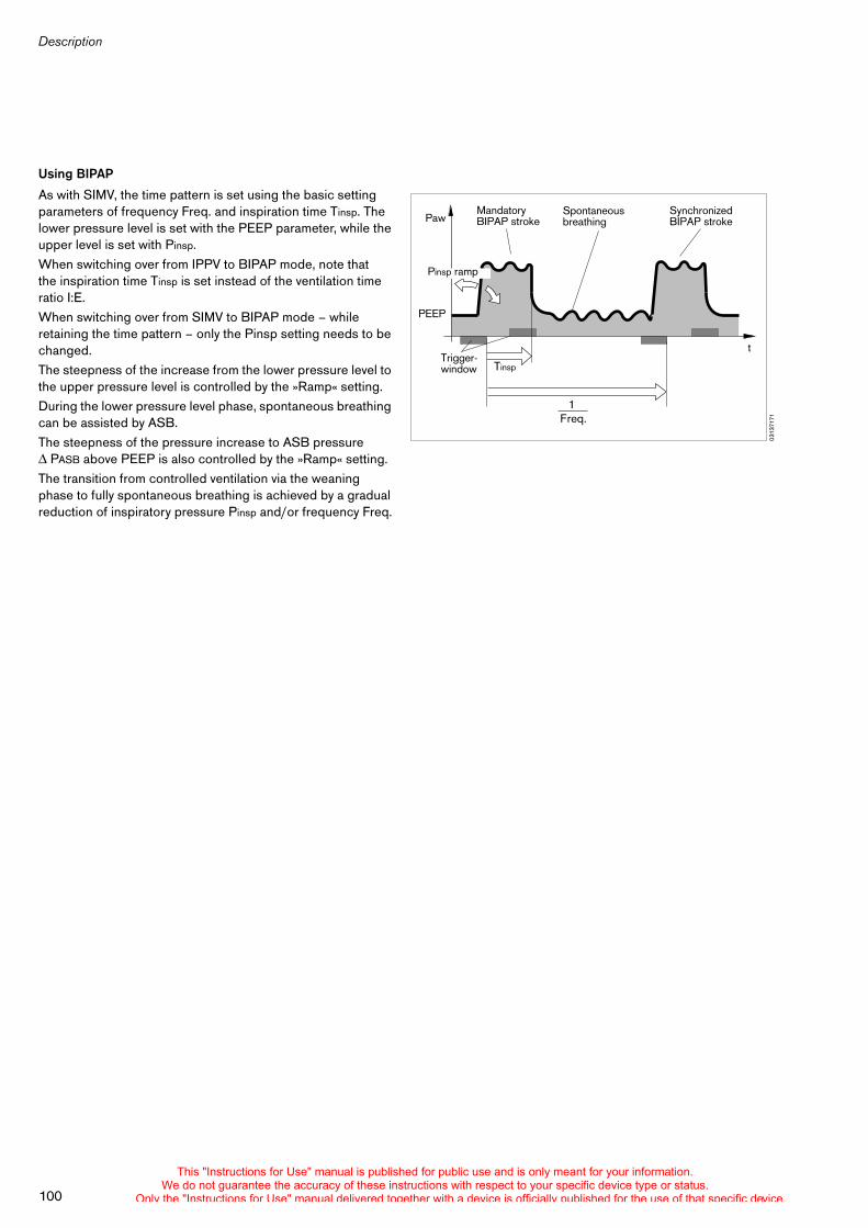
Description
100
Using BIPAP
As with SIMV, the time pattern is set using the basic setting parameters of frequency Freq. and inspiration time Tinsp. The lower pressure level is set with the PEEP parameter, while the upper level is set with Pinsp.When switching over from IPPV to BIPAP mode, note that the inspiration time Tinsp is set instead of the ventilation time ratio I:E.When switching over from SIMV to BIPAP mode – while retaining the time pattern – only the Pinsp setting needs to be changed.The steepness of the increase from the lower pressure level to the upper pressure level is controlled by the »Ramp« setting.During the lower pressure level phase, spontaneous breathing can be assisted by ASB.The steepness of the pressure increase to ASB pressure
PASB above PEEP is also controlled by the »Ramp« setting.The transition from controlled ventilation via the weaning phase to fully spontaneous breathing is achieved by a gradual reduction of inspiratory pressure Pinsp and/or frequency Freq.
0313
7171
Paw
PEEP
tTrigger-window
Spontaneous breathing
Mandatory BIPAP stroke
Synchronized BIPAP stroke
Tinsp
Freq.1
Pinsp ramp
This "Instructions for Use" manual is published for public use and is only meant for your information.We do not guarantee the accuracy of these instructions with respect to your specific device type or status.
Only the "Instructions for Use" manual delivered together with a device is officially published for the use of that specific device.
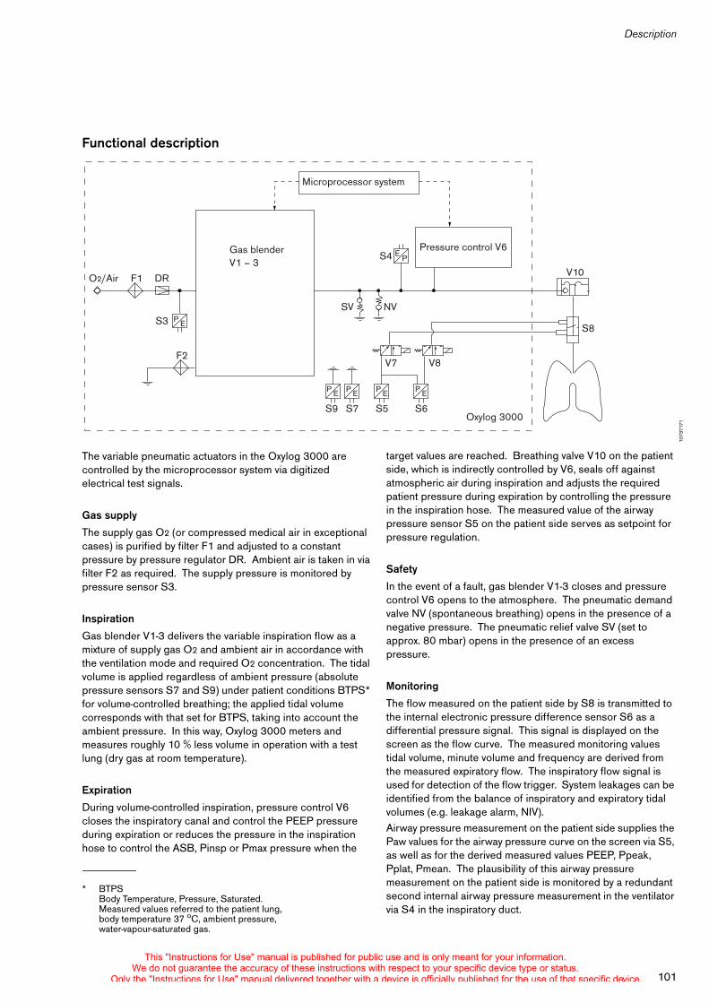
101
Description
target values are reached. Breathing valve V10 on the patient side, which is indirectly controlled by V6, seals off against atmospheric air during inspiration and adjusts the required patient pressure during expiration by controlling the pressure in the inspiration hose. The measured value of the airway pressure sensor S5 on the patient side serves as setpoint for pressure regulation.
Safety
In the event of a fault, gas blender V1-3 closes and pressure control V6 opens to the atmosphere. The pneumatic demand valve NV (spontaneous breathing) opens in the presence of a negative pressure. The pneumatic relief valve SV (set to approx. 80 mbar) opens in the presence of an excess pressure.
Monitoring
The flow measured on the patient side by S8 is transmitted to the internal electronic pressure difference sensor S6 as a differential pressure signal. This signal is displayed on the screen as the flow curve. The measured monitoring values tidal volume, minute volume and frequency are derived from the measured expiratory flow. The inspiratory flow signal is used for detection of the flow trigger. System leakages can be identified from the balance of inspiratory and expiratory tidal volumes (e.g. leakage alarm, NIV).Airway pressure measurement on the patient side supplies the Paw values for the airway pressure curve on the screen via S5, as well as for the derived measured values PEEP, Ppeak, Pplat, Pmean. The plausibility of this airway pressure measurement on the patient side is monitored by a redundant second internal airway pressure measurement in the ventilator via S4 in the inspiratory duct.
Functional description
The variable pneumatic actuators in the Oxylog 3000 are controlled by the microprocessor system via digitized electrical test signals.
Gas supply
The supply gas O2 (or compressed medical air in exceptional cases) is purified by filter F1 and adjusted to a constant pressure by pressure regulator DR. Ambient air is taken in via filter F2 as required. The supply pressure is monitored by pressure sensor S3.
Inspiration
Gas blender V1-3 delivers the variable inspiration flow as a mixture of supply gas O2 and ambient air in accordance with the ventilation mode and required O2 concentration. The tidal volume is applied regardless of ambient pressure (absolute pressure sensors S7 and S9) under patient conditions BTPS* for volume-controlled breathing; the applied tidal volume corresponds with that set for BTPS, taking into account the ambient pressure. In this way, Oxylog 3000 meters and measures roughly 10 % less volume in operation with a test lung (dry gas at room temperature).
Expiration
During volume-controlled inspiration, pressure control V6 closes the inspiratory canal and control the PEEP pressure during expiration or reduces the pressure in the inspiration hose to control the ASB, Pinsp or Pmax pressure when the
1073
7171
* BTPSBody Temperature, Pressure, Saturated.Measured values referred to the patient lung, body temperature 37 oC, ambient pressure, water-vapour-saturated gas.
Microprocessor system
Oxylog 3000
Pressure control V6
O2/Air F1
F2
DR
SV
S8
S4
S9 S7 S5 S6
NV
V10
V7 V8
S3
Gas blenderV1 – 3
P
P
E
P E P E P E P E
E
This "Instructions for Use" manual is published for public use and is only meant for your information.We do not guarantee the accuracy of these instructions with respect to your specific device type or status.
Only the "Instructions for Use" manual delivered together with a device is officially published for the use of that specific device.
102
Order List
Order List
Part name Part No.
Workstation
Oxylog 3000 2M 86300
Basic unit
Oxylog 3000 2M 86955
Accessories required for operation
Power supply:
AC/DC power pack 100-240 V/50-60 Hz 2M 86 730
Available power cables:
Germany and Europe 18 24 481
Denmark 18 44 342
United Kingdom 18 44 369
Australia 18 44 350
Switzerland 18 44 377
USA 18 41 793
DC/DC converter 2M 86 731
Nickel metal hydride batteryor
2M 86 732
Lithium ion battery 2M 86 733
Reusable ventilation hose set, comprising:
Ventilation hose with measuring leads, 1.5 m 84 12 068
Ventilation hose with measuring leads, 3 m 84 12 913
Breathing valve 84 12 001
Flow sensor 84 12 034
Angled connector 84 12 235
Disposable ventilation hose set (set of 5): 2M 86 841
Test lung 84 03 201
Connecting hoses:
O2/Air hosefor use on the pressure reducer Screw thread M 12 x 1 and 15 x 1
Length 1.5 m M 17 616
Length 3.0 m 2M 86 687
ZV*-O2/Air Air connecting hose with angled connector for central supply and DIN connection
Length 1.5 m M 29 285
Length 3.0 m M 29 245
Length 5.0 m M 29 265
ZV-O2/Air Air connecting hose with angled connector for central supply and NIST connection
Length 1.5 m M 34 410
Length 3.0 m M 34 411
Length 5.0 m M 34 412
Special accessories
Wall bracket (for portable system) 2M 86 725
Onboard equipment holder 2M 86 900
Wall adapter 2M 86 934
Set of "Adult" catheter connectors 84 03 685
Corrugated hose 84 02 041
Connector for O2 inhalation M 20 101
Oxylog 3000 battery charging station 2M 86 729
Options
BIPAP (PCV+) ME 05 056
ASB (PS) ME 05 055
O2 blending ME 05 054
100 % O2 ME 05 053
O2 inhalation ME 05 052
* Central piped gas supply
Part name Part No.
This "Instructions for Use" manual is published for public use and is only meant for your information.We do not guarantee the accuracy of these instructions with respect to your specific device type or status.
Only the "Instructions for Use" manual delivered together with a device is officially published for the use of that specific device.
103
Order List
Part name Part No.
Oxylog 3000 emergency rescue units
Portable system, complete 2M 86 970
For supplying the Oxylog 3000 from a piped medical gas supply or cylinder via an O2 manifold, comprising:Oxylog 3000Ventilation hose with measuring leadsBreathing valveFlow sensorAngled connectorO2 cylinder, 2.5 LO2 pressure reducerO2 manifoldEquipment bags
This "Instructions for Use" manual is published for public use and is only meant for your information.We do not guarantee the accuracy of these instructions with respect to your specific device type or status.
Only the "Instructions for Use" manual delivered together with a device is officially published for the use of that specific device.
Index
104
Index
100 % O2 . . . . . . . . . . . . . . . . . . . . . . . . . . . . . . . . . . . . . . . . . 48
Abbreviations . . . . . . . . . . . . . . . . . . . . . . . . . . . . . . . . . . . . . 84Accessories . . . . . . . . . . . . . . . . . . . . . . . . . . . . . . . . . . . . . . . . . 6Advisory . . . . . . . . . . . . . . . . . . . . . . . . . . . . . . . . . . . . . . . . . . 46Air Mix . . . . . . . . . . . . . . . . . . . . . . . . . . . . . . . . . . . . . . . . . . . 42Alarms screen window . . . . . . . . . . . . . . . . . . . . . . . . . . . . . . 13Ambient conditions . . . . . . . . . . . . . . . . . . . . . . . . . . . . . . . . 88Angled connector . . . . . . . . . . . . . . . . . . . . . . . . . . . . . . . . . . 16Apnoea ventilation . . . . . . . . . . . . . . . . . . . . . . . . . . . . . . . . . 39Areas of explosion hazard . . . . . . . . . . . . . . . . . . . . . . . . . . . . . 6Areas of use . . . . . . . . . . . . . . . . . . . . . . . . . . . . . . . . . . . . . . . . 8ASB . . . . . . . . . . . . . . . . . . . . . . . . . . . . . . . . . . . . . . . . . . . . . 98
Bacterial filter . . . . . . . . . . . . . . . . . . . . . . . . . . . . . . . . . . . . . 17Bath disinfecting . . . . . . . . . . . . . . . . . . . . . . . . . . . . . . . . . . . 61Battery capacity . . . . . . . . . . . . . . . . . . . . . . . . . . . . . . . . . . . 20Battery operation . . . . . . . . . . . . . . . . . . . . . . . . . . . . . . . . . . 20Battery type . . . . . . . . . . . . . . . . . . . . . . . . . . . . . . . . . . . . . . . 52BIPAP, BIPAP / ASB . . . . . . . . . . . . . . . . . . . . . . . . . . . . . . . 37Breathing valve . . . . . . . . . . . . . . . . . . . . . . . . . . . . . . . . . . . . 59BTPS . . . . . . . . . . . . . . . . . . . . . . . . . . . . . . . . . . . . . . . . . . . . 84
Calibration . . . . . . . . . . . . . . . . . . . . . . . . . . . . . . . . . . . . . . . . 50Care . . . . . . . . . . . . . . . . . . . . . . . . . . . . . . . . . . . . . . . . . . . . . 58Carrier System 3000 (optional) . . . . . . . . . . . . . . . . . . . . . . 72Caution . . . . . . . . . . . . . . . . . . . . . . . . . . . . . . . . . . . . . . . . . . 45Charging the battery . . . . . . . . . . . . . . . . . . . . . . . . . . . . . . . 20Checking readiness for operation . . . . . . . . . . . . . . . . . . . . 26Cleaning . . . . . . . . . . . . . . . . . . . . . . . . . . . . . . . . . . . . . . . . . 60CMV . . . . . . . . . . . . . . . . . . . . . . . . . . . . . . . . . . . . . . . . . . . . . 33CMVAssist . . . . . . . . . . . . . . . . . . . . . . . . . . . . . . . . . . . . . . . . 33Configuration . . . . . . . . . . . . . . . . . . . . . . . . . . . . . . . . . . . . . 51CPAP, CPAP / ASB . . . . . . . . . . . . . . . . . . . . . . . . . . . . . . . 38Curves . . . . . . . . . . . . . . . . . . . . . . . . . . . . . . . . . . . . . . . . . . . 47Customer Service Mode . . . . . . . . . . . . . . . . . . . . . . . . . . . . 76
DC/DC converter . . . . . . . . . . . . . . . . . . . . . . . . . . . . . . . . . . 21Description . . . . . . . . . . . . . . . . . . . . . . . . . . . . . . . . . . . . . . . 96Disinfecting . . . . . . . . . . . . . . . . . . . . . . . . . . . . . . . . . . . . . . . 60Disinfecting by wiping . . . . . . . . . . . . . . . . . . . . . . . . . . . . . . 61Display accu . . . . . . . . . . . . . . . . . . . . . . . . . . . . . . . . . . . . . . 80Display actual technical error . . . . . . . . . . . . . . . . . . . . . . . . 80Display language text . . . . . . . . . . . . . . . . . . . . . . . . . . . . . . . 81Display logbook . . . . . . . . . . . . . . . . . . . . . . . . . . . . . . . . . . . 81Disposable hose set . . . . . . . . . . . . . . . . . . . . . . . . . . . 18, 69
Event of an Alarm . . . . . . . . . . . . . . . . . . . . . . . . . . . . . . 45, 54Exit service mode . . . . . . . . . . . . . . . . . . . . . . . . . . . . . . . . . . 82External power supply . . . . . . . . . . . . . . . . . . . . . . . . . . . . . . 21
Fault – cause – remedy . . . . . . . . . . . . . . . . . . . . . . . . . . . . . 54
Flow curves main page . . . . . . . . . . . . . . . . . . . . . . . . . . . . . 13Front panel – standard version . . . . . . . . . . . . . . . . . . . . . . . 66Front panel with all options . . . . . . . . . . . . . . . . . . . . . . . . . . 67
Gas failure . . . . . . . . . . . . . . . . . . . . . . . . . . . . . . . . . . . . . . . . 46Gas supply . . . . . . . . . . . . . . . . . . . . . . . . . . . . . . . . . . . . . . . . 22
Heart-lung resuscitation . . . . . . . . . . . . . . . . . . . . . . . . . . . . . 35HME (Heat Moisture Exchanger) . . . . . . . . . . . . . . . . . . . . . 17Hyperbaric chambers . . . . . . . . . . . . . . . . . . . . . . . . . . . . . . . . 6
Information window . . . . . . . . . . . . . . . . . . . . . . . . . . . . . . . . 14Informations . . . . . . . . . . . . . . . . . . . . . . . . . . . . . . . . . . . . . . . 51Inspiration hold . . . . . . . . . . . . . . . . . . . . . . . . . . . . . . . . . . . . 48Intended medical use . . . . . . . . . . . . . . . . . . . . . . . . . . . . . . . . 8Internal supply with rechargeable battery . . . . . . . . . . . . . . 19IPPV, IPPVAssist . . . . . . . . . . . . . . . . . . . . . . . . . . . . . . . . . . 33
Liability . . . . . . . . . . . . . . . . . . . . . . . . . . . . . . . . . . . . . . . . . . . . 6
Magnetic resonance imaging . . . . . . . . . . . . . . . . . . . . . . . . . 6Maintenance . . . . . . . . . . . . . . . . . . . . . . . . . . . . . . . . . . . . . . . 6Maintenance intervals . . . . . . . . . . . . . . . . . . . . . . . . . . . . . . 62Manual inspiration . . . . . . . . . . . . . . . . . . . . . . . . . . . . . . . . . 48Manual ventilation equipment . . . . . . . . . . . . . . . . . . . . . . . . . 6Measured value display . . . . . . . . . . . . . . . . . . . . . . . . . . . . . 89Measured values . . . . . . . . . . . . . . . . . . . . . . . . . . . . . . . . . . . 47MIL STD 810 E . . . . . . . . . . . . . . . . . . . . . . . . . . . . . . . . . . . . 92Mobile phones . . . . . . . . . . . . . . . . . . . . . . . . . . . . . . . . . . . . . 6Monitoring . . . . . . . . . . . . . . . . . . . . . . . . . . . . . . . . . . . . . . . . 90
NIV Non-invasive ventilation . . . . . . . . . . . . . . . . . . . . . . . . . 41No Air Mix . . . . . . . . . . . . . . . . . . . . . . . . . . . . . . . . . . . . . . . . 42
O2 inhalation . . . . . . . . . . . . . . . . . . . . . . . . . . . . . . . . . . . . . . . 8Onboard Equipment Holder . . . . . . . . . . . . . . . . . . . . . . . . . 74Operating concept . . . . . . . . . . . . . . . . . . . . . . . . . . . . . . . . . 10Operating data . . . . . . . . . . . . . . . . . . . . . . . . . . . . . . . . . . . . 90Operation . . . . . . . . . . . . . . . . . . . . . . . . . . . . . . . . . . . . . . . . . 32Optional "O2 blending" . . . . . . . . . . . . . . . . . . . . . . . . . . . . . 42
PCV+ . . . . . . . . . . . . . . . . . . . . . . . . . . . . . . . . . . . . . . . . . . . . 99Performance data . . . . . . . . . . . . . . . . . . . . . . . . . . . . . . . . . . 89Piped medical gas system . . . . . . . . . . . . . . . . . . . . . . . . . . . 24Pneumatic operation time . . . . . . . . . . . . . . . . . . . . . . . . . . . 23Pollutants . . . . . . . . . . . . . . . . . . . . . . . . . . . . . . . . . . . . . . . . . . 6Power supply . . . . . . . . . . . . . . . . . . . . . . . . . . . . . . . . . . . . . . 19Power supply unit . . . . . . . . . . . . . . . . . . . . . . . . . . . . . . . . . . 21Precautions . . . . . . . . . . . . . . . . . . . . . . . . . . . . . . . . . . . . . . . . 6Pressure curves main page . . . . . . . . . . . . . . . . . . . . . . . . . . 13Pressure limitation . . . . . . . . . . . . . . . . . . . . . . . . . . . . . . . . . 44
This "Instructions for Use" manual is published for public use and is only meant for your information.We do not guarantee the accuracy of these instructions with respect to your specific device type or status.
Only the "Instructions for Use" manual delivered together with a device is officially published for the use of that specific device.
105
Index
Primary care . . . . . . . . . . . . . . . . . . . . . . . . . . . . . . . . . . . . . . . 10PS . . . . . . . . . . . . . . . . . . . . . . . . . . . . . . . . . . . . . . . . . . . . . . . 98
Replacing the battery . . . . . . . . . . . . . . . . . . . . . . . . . . . . . . . 19Reusable hose set . . . . . . . . . . . . . . . . . . . . . . . . . . . . . 16, 69Routine and additional functions . . . . . . . . . . . . . . . . . . . . . . 11RTCA DO–160D . . . . . . . . . . . . . . . . . . . . . . . . . . . . . . . . . . . 92
Screen Operating Controls . . . . . . . . . . . . . . . . . . . . . . . . . . 11Screen windows . . . . . . . . . . . . . . . . . . . . . . . . . . . . . . . . . . . 12Secondary transfers . . . . . . . . . . . . . . . . . . . . . . . . . . . . . . . . 10Service Mode . . . . . . . . . . . . . . . . . . . . . . . . . . . . . . . . . . . . . . 75Set data and time . . . . . . . . . . . . . . . . . . . . . . . . . . . . . . . . . . 78Set gas supply . . . . . . . . . . . . . . . . . . . . . . . . . . . . . . . . . . . . . 52Set language . . . . . . . . . . . . . . . . . . . . . . . . . . . . . . . . . . . . . . 52Set startup settings . . . . . . . . . . . . . . . . . . . . . . . . . . . . . . . . . 77Setting alarm limits . . . . . . . . . . . . . . . . . . . . . . . . . . . . . . . . . 44Settings . . . . . . . . . . . . . . . . . . . . . . . . . . . . . . . . . . . . . . . . . . . 88Settings screen window . . . . . . . . . . . . . . . . . . . . . . . . . . . . . 12Shutdown . . . . . . . . . . . . . . . . . . . . . . . . . . . . . . . . . . . . . . . . . 50SIMV . . . . . . . . . . . . . . . . . . . . . . . . . . . . . . . . . . . . . . . . . . . . . 97SIMV, SIMV / ASB . . . . . . . . . . . . . . . . . . . . . . . . . . . . . . . . . 36Special functions . . . . . . . . . . . . . . . . . . . . . . . . . . . . . . . . . . . 48Suppress alarm tones . . . . . . . . . . . . . . . . . . . . . . . . . . . . . . . 46Symbols . . . . . . . . . . . . . . . . . . . . . . . . . . . . . . . . . . . . . . . . . . 85
Technical Data . . . . . . . . . . . . . . . . . . . . . . . . . . . . . . . . . . . . . 88Test buttons . . . . . . . . . . . . . . . . . . . . . . . . . . . . . . . . . . . . . . . 79Test buzzer . . . . . . . . . . . . . . . . . . . . . . . . . . . . . . . . . . . . . . . . 80Test display . . . . . . . . . . . . . . . . . . . . . . . . . . . . . . . . . . . . . . . 80Test LEDs . . . . . . . . . . . . . . . . . . . . . . . . . . . . . . . . . . . . . . . . . 80Test loudspeaker . . . . . . . . . . . . . . . . . . . . . . . . . . . . . . . . . . . 80Test lung . . . . . . . . . . . . . . . . . . . . . . . . . . . . . . . . . . . . . . . . . . 26Test potentiometer . . . . . . . . . . . . . . . . . . . . . . . . . . . . . . . . . 79Test supply data . . . . . . . . . . . . . . . . . . . . . . . . . . . . . . . . . . . . 80Trigger (IPPVAssist) . . . . . . . . . . . . . . . . . . . . . . . . . . . . . . . . 34
Values screen window . . . . . . . . . . . . . . . . . . . . . . . . . . . . . . 12Ventilation modes . . . . . . . . . . . . . . . . . . . . . . . . . . . . . . . . . . . 8
Wall bracket . . . . . . . . . . . . . . . . . . . . . . . . . . . . . . . . . . . . . . 102Warning . . . . . . . . . . . . . . . . . . . . . . . . . . . . . . . . . . . . . . . . . . 45What's what . . . . . . . . . . . . . . . . . . . . . . . . . . . . . . . . . . . . . . . 66
This "Instructions for Use" manual is published for public use and is only meant for your information.We do not guarantee the accuracy of these instructions with respect to your specific device type or status.
Only the "Instructions for Use" manual delivered together with a device is officially published for the use of that specific device.

106
This "Instructions for Use" manual is published for public use and is only meant for your information.We do not guarantee the accuracy of these instructions with respect to your specific device type or status.
Only the "Instructions for Use" manual delivered together with a device is officially published for the use of that specific device.

107
This "Instructions for Use" manual is published for public use and is only meant for your information.We do not guarantee the accuracy of these instructions with respect to your specific device type or status.
Only the "Instructions for Use" manual delivered together with a device is officially published for the use of that specific device.
Dräger Medical AG & Co. KGaAGermanyz Moislinger Allee 53 – 55
D- 23542 Lübecky +49 451 8 82- 0x 26 80 70FAX +49 451 8 82- 20 80! http://www.draeger.com
These Instructions for Use apply only toOxylog 3000with Serial No.:
If no Serial No. has been filled in by Dräger these Instructions for Use are provided for general information only and are not intended for use with any specific machine or device.
çDirective 93/42/EEC concerning Medical Devices
90 37 171 - GA 5503.403 en© Dräger Medical AG & Co. KGaA2nd edition – April 2002 Subject to alteration
This "Instructions for Use" manual is published for public use and is only meant for your information.We do not guarantee the accuracy of these instructions with respect to your specific device type or status.
Only the "Instructions for Use" manual delivered together with a device is officially published for the use of that specific device.