Embed Size (px)
Citation preview

Dräger. Technology for Life®i
D
enInstructions for Use
Dräger Flame 3000Visual Flame DetectorInstructions for Use
WARNINGStrictly follow the Instructions for Use. The user must fully understand and strictly observe the instructions. Use the product only for the purposes specified in the Intended Use section of this document.
!


3Dräger Flame 3000
Contents1 For your safety....................................................................41.1 General safety statements....................................................41.2 Special and product-specific safety statements ...................41.3 Definitions of alert icons .......................................................4
2 Description ..........................................................................52.1 Product overview ..................................................................52.2 Feature description ...............................................................52.3 Intended use .........................................................................82.4 Limitations on use.................................................................82.5 Approvals..............................................................................82.6 Explanation of type-identifying marking and symbols ..........8
3 Use .......................................................................................93.1 Prerequisites for installation .................................................93.2 Installation ..........................................................................103.3 Commissioning and functional testing ................................14
4 Troubleshooting ...............................................................15
5 Maintenance ......................................................................16
6 Disposal.............................................................................176.1 Disposal of electrical and electronic equipment .................17
7 Technical data ...................................................................187.1 Electrical specification ........................................................187.2 Mechanical specification.....................................................187.3 Environmental specification ................................................187.4 Operating specification .......................................................18
8 Order list............................................................................198.1 Dräger Flame 3000 variants ...............................................198.2 Accessories ........................................................................19
Contents
4 Dräger Flame 3000
1 For your safety1.1 General safety statements
● Before using this product, carefully read the Instructions for Use.• Strictly follow the Instructions for Use. The user must fully understand
and strictly observe the instructions. Use the product only for the purposes specified in the Intended Use section of this document.
• Do not dispose of the Instructions for Use. Ensure that they are retained and appropriately used by the product user.
• Only fully trained and competent users are permitted to use this product.
• Comply with all local and national rules and regulations associated with this product.
• Only trained and competent personnel are permitted to inspect, repair and service the product as detailed in these Instructions for Use (see Section 5). Further maintenance work that is not detailed in these Instructions for Use must only be carried out by Dräger or personnel qualified by Dräger. Dräger recommend a Dräger service contract for all maintenance activities.
• Use only genuine Dräger spare parts and accessories, or the proper functioning of the product may be impaired.
• Do not use a faulty or incomplete product, and do not modify the product.
• Notify Dräger in the event of any component fault or failure.
1.2 Special and product-specific safety statements
• This product is approved according to ATEX directive 94/9/EG. It must only be used under the conditions specified in the approval certificate.
• Ensure that all site permits, procedures and practices are followed when installing, using and maintaining the product.
1.3 Definitions of alert icons
Alert icons are used in this document to provide and highlight text that requires a greater awareness by the user. A definition of the meaning of each icon is as follows:
WARNINGIndicates a potentially hazardous situation which, if not avoided, could result in death or serious injury.
CAUTIONIndicates a potentially hazardous situation which, if not avoided, could result in physical injury or damage to the product or environment. It may also be used to alert against unsafe practices.
NOTICEIndicates additional information on how to use the product.
!
!
ii
For your safety

5Dräger Flame 3000
2 Description2.1 Product overview
The Dräger Flame 3000 is a visual flame detector. It uses an imaging device, digital signal processing hardware and firmware algorithms to interpret the visual characteristics of flame. It is capable of operating independently; external control equipment is not required for normal functions. The Dräger Flame 3000 can be integrated into Dräger and third party control systems.
The Dräger Flame 3000 comprises the following main components:
• Front enclosure cover (including the window)• Detector assembly• Enclosure body• Terminal connections• Rear enclosure cover• Mounting bracket
The Dräger Flame 3000 is supplied preassembled and includes the mounting bracket. However, it is not supplied with a mounting support and fixings, cabling or glands.
2.2 Feature description
2.2.1 Sensitivity
The sensitivity of the Dräger Flame 3000 to different fuel sources is dependent on the visible size of the fire.
The Dräger Flame 3000 has also a high degree of insensitivity to common sources of false alarms: reflected flare radiation, arc welding, hot objects, and engine exhausts.
3883
Description

6 Dräger Flame 3000
2.2.2 Field of view
The Dräger Flame 3000 has a horizontal field of view of 120° and vertical field of view of 80°. It does not have a traditional cone of vision like infrared flame detectors. Its field of view is a rectangular pyramidal shape and represents a radial projection of the rectangular sensing element within the detector assembly. The typical field of view and detectable range of a 0.1 m2 n-Heptane pan fire is illustrated below.
3881
Description
7Dräger Flame 3000
2.2.3 Optical test
There are four LEDs located behind the enclosure window. They emit infrared light that is reflected by both the internal and external surfaces of the enclosure window. The reflections are continually monitored by the detector and if they are disturbed the detector signals an optical fault.
The optics of the Dräger Flame 3000 can also be checked using the Dräger FS-5000 Flame Simulator.
2.2.4 Explosive atmosphere protection
The Dräger Flame 3000 is certified for use in some potentially explosive atmospheres. The explosion protection approval is valid for use of the device in gas/vapour-air mixtures of combustible gases and vapours under atmospheric conditions. The explosion protection is not valid for use in oxygen-enriched atmospheres.
WARNINGDo not open the enclosure in the presence of an explosive atmosphere as it could lead to an explosion.
Ensure that the flame path of the Dräger Flame 3000 is not damaged during installation. A damaged flame path could lead to an explosion.
CAUTIONOnly appropriately trained service personnel may open the enclosure. Incorrect disassembly of the Dräger Flame 3000 may damage the equipment.
!
!
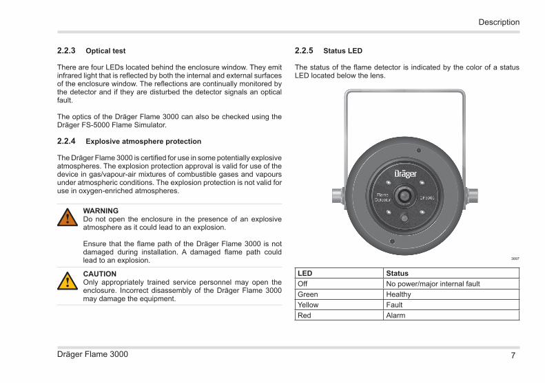
2.2.5 Status LED
The status of the flame detector is indicated by the color of a status LED located below the lens.
LED StatusOff No power/major internal faultGreen HealthyYellow FaultRed Alarm
3897
Description
8 Dräger Flame 3000
2.3 Intended use
The Dräger Flame 3000 is intended for use in areas that may contain a potentially explosive atmosphere (see Section 2.5 for details of the explosive environments in which the Dräger Flame 3000 can be used). It is used to monitor an area and trigger the necessary control actions upon the detection of fire or flame within its field of view.
2.4 Limitations on use
• The Dräger Flame 3000 is not approved for use in oxygen-enriched atmospheres.
• As the Dräger Flame 3000 responds to visible flame, it cannot be used in locations where flare stacks and other open flames are within its field of view without triggering false alarms.
• The Dräger Flame 3000 is unable to detect fires that are invisible to the naked eye, such as those using pure hydrogen, methanol and sulphur as fuel.
• The sensitivity of the Dräger Flame 3000 to flame is reduced by obscurants such as smoke, fog and other airborne particulates. The Dräger Flame 3000 may be blinded by extremely dense obscurants.
• Although the Dräger Flame 3000 is insensitive to arc welding, arc welding should not take place within 1 m of the flame detector.
2.5 Approvals
ATEX: Certificate number FM07ATEX 0033, II 2 G Exd IIC
IECEx: Certificate number FME 07.0002
FM: Class I Div 1 Groups B, C, D, T4, ambient: -60 °C to +85 °C; Class I Zone 1 AEx/Ex d IIC T4, ambient: -60 °C to +85 °C
CE: GEC EN55022 & 082
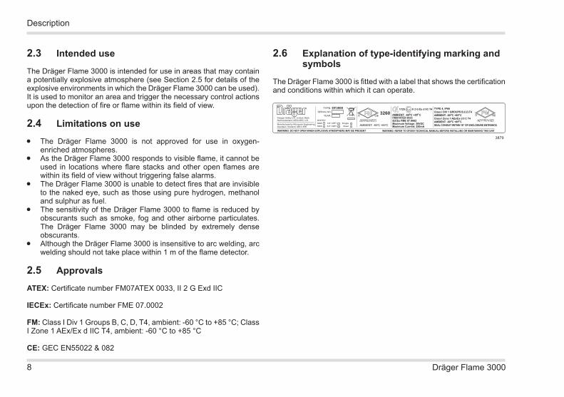
2.6 Explanation of type-identifying marking and symbols
The Dräger Flame 3000 is fitted with a label that shows the certification and conditions within which it can operate.
WARNING: REFER TO DF3000 TECHNICAL MANUAL BEFORE INSTALLING OR MAINTAINING THIS UNIT
Draeger Safety U.K. Limited, Blyth,Northumberland, NE24 4RG, U.K.
Manufactured by Micropack EngineeringAberdeen, Scotland, AB12 4RR
TYPE: DF3000SERIAL NO: YEAR:
ENTRY:M25 1/2” NPT SingleM20 3/4” NPT Duel
3260
AMBIENT: -60 C +85 C
WARNING: DO NOT OPEN WHEN EXPLOSIVE ATMOSPHERE MAY BE PRESENT
1725 II 2 G Ex d IIC T4
AMBIENT: -60 C +85 CFM07ATEX 0033IECEx FME 07.0002Maximum Voltage: 30VDCMaximum Current: 250mA
TYPE 4, IP66Class I DIV 1 GROUPS B,C,D,T4AMBIENT: -60 C +85 CClass I Zone 1 AEx/Ex d II C T4AMBIENT: -60 C +85 CSEAL CONDUIT WITHIN 18” OF ENCLOSURE ENTRANCE
3879
Description

9Dräger Flame 3000
3 Use3.1 Prerequisites for installation
When selecting a mounting position for the Dräger Flame 3000 observe the following:
• Ensure that the Dräger Flame 3000 has an unobstructed view of the areas to be protected.
• Ensure that the mounting position is free from vibration or movement.
• Ensure that the mounting position has sufficient support for the Dräger Flame 3000 and allows for horizontal adjustment.
• Ensure that the Dräger Flame 3000 is protected from sources of impact damage and from being knocked out of alignment.
• Install the Dräger Flame 3000 as far away as possible from local sources of possible electrical interference, such as X-rays, RF (radio frequency) interference or electrostatic discharge.
• Ensure that the area under observation has sufficient detector coverage for all possible hazards (multiple detectors may be required) taking into account any obstructions and congestion.
• Minimize the exposure of the enclosure front cover window to contaminants such as oil, water (deluge water, rain and sea spray), snow, and ice. Where the Dräger Flame 3000 is to be mounted at a low level avoid contamination from equipment situated above the mounting position.
• If dense smoke is expected to accumulate at the onset of the fire, the Dräger Flame 3000 should be mounted 1 – 2 m below the ceiling level where possible.
• Ensure there is maintenance access to the Dräger Flame 3000 (e.g. direct, ladder or scaffold access).
• Ensure that mounting supports are compatible with the Dräger Flame 3000 mounting brackets.
• Ensure that the Dräger Flame 3000 does not have a direct view
of any sources of flame used during normal operations, such as flare stacks.
• Ensure that the Dräger Flame 3000 is positioned so that it is not directly facing the sun.
All of these issues are crucial to a successful installation. They should be observed during the detailed design, construction and commissioning phases of the installation of a fire detection system.
3.1.1 Detector coverage
Software analysis of the actual detector field of view may be required to ensure adequate coverage of the hazards. This analysis can also be used to optimize the number of detectors and the loop configuration.
3.1.2 Power and cable requirements
The Dräger Flame 3000 requires a supply voltage of 18 – 30 V at the input terminals.
The installation location and local regulations and standards determine the cable specification.
The Dräger Flame 3000 contains further details of the power and cable selection requirements. Contact Dräger for details.
Use

10 Dräger Flame 3000
3.2 Installation
WARNINGDo not open the enclosure in an explosive atmosphere as it could lead to an explosion.
Ensure that the flame path of the Dräger Flame 3000 is not damaged during installation. A damaged flame path could lead to an explosion.
Do not drill holes in the enclosure as it could lead to an explosion.
CAUTIONThe Dräger Flame 3000 may be damaged by high voltage insulation tests and other cable testing operations. It should only be installed after these tests are complete.
Do not drop or knock the enclosure as this may damage the detector assembly.
Only appropriately trained service personnel may open the enclosure. Incorrect disassembly of the Dräger Flame 3000 may damage the equipment.
NOTICEBefore installing the Dräger Flame 3000 it is advisable to check the mounting locations to ensure that there have been no changes made during construction that will affect detector coverage.
!
!
ii
3.2.1 Mechanical
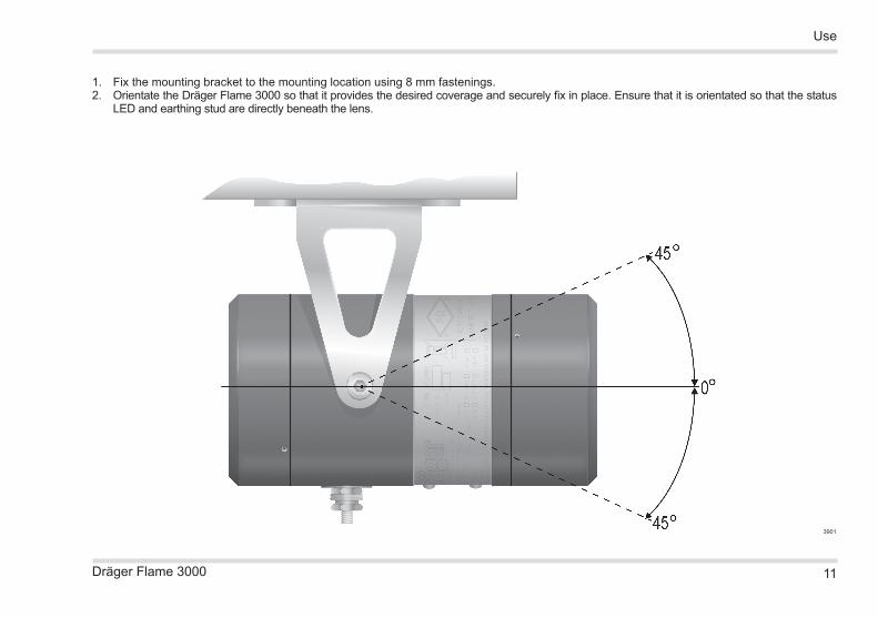
The mounting bracket allows the vertical orientation of the Dräger Flame 3000 to be adjusted from 0 to 45°, and allows a horizontal rotation of up to 90°.
3883
Use
11Dräger Flame 3000
1. Fix the mounting bracket to the mounting location using 8 mm fastenings.2. Orientate the Dräger Flame 3000 so that it provides the desired coverage and securely fix in place. Ensure that it is orientated so that the status
LED and earthing stud are directly beneath the lens.
3901
Use

12 Dräger Flame 3000
3.2.2 Electrical
CAUTION The Dräger Flame 3000 must be properly grounded. Failure to
do so may cause electrical interference in the equipment.
Do not over tighten the cable glands. Metric cable entries are fitted with an internal stop that results in the threads being visible after assembly. Over tightening may result in damage to both the cable entry and the gland.
NOTICE A 2 m helix should be allowed in the Dräger Flame 3000
cabling. This allows the detector to be repositioned if local obstructions, such as pipework and cable trays, block the detector’s view of the local hazard.
The Dräger Flame 3000 can operate via a standard 3 or 4 wire termination and has two types of alarm output available simultaneously:
• 4 – 20 mA• Relay (alarm and fault)
The 4 – 20 mA signal outputs are as follows:
!
ii
Flame 3000internal connections Flame 3000 terminal
Flame 3000field connections
1 (+ 24 V)
2 (0 V)
3 (A)
4 (B)
5 (4 – 20mA)
6 (0 V)
7 (+ 24 V)
8 (0 V)
9 (C)
10 (B)
11 (B)
12 (Alarm)
+ 24 Vdc
0 Vdc
To fire panel
To fire panel
4 – 20mA source
0 Vdc
+ 24 Vdc
0 Vdc
End-of-lineresistor
Alarm
Alarm relay(normally open)
Fault relay(normally
closed)
Event OutputPower/detector fault 0 mAOptical fault 2 mAHealthy condition 4 mAAlarm 18 mAOver-range 21 mA
The internal connections of the alarm and fault relay contacts and jumpers are shown in below. Each field connection is also shown on this illustration for clarity.
The end-of-line and alarm resistances are to be calculated based on the requirements of the control system.
3880
1. Isolate all associated power supplies. Ensure that they remain isolated until required for commissioning.
2. Connect the enclosure earth stud to a local ground point.3. Remove the blanking plug(s) from the enclosure gland entries.4. Fit the cable gland to the enclosure. Ensure that it is fitted with a
minimum of five threads inside the enclosure and with the ingress protection seal washer fitted at the bottom of the thread. Tighten the gland to a torque between 15 – 20 Nm (11 – 15 lbf ft).
5. Loosen the set screw located in the rear enclosure cover. Unscrew and remove the rear enclosure.
Use
13Dräger Flame 3000
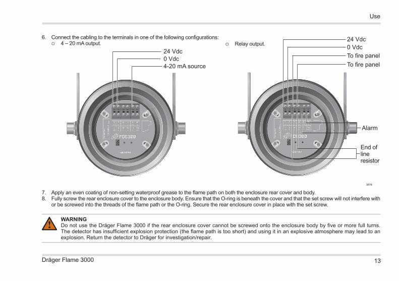
6. Connect the cabling to the terminals in one of the following configurations: 4 – 20 mA output. Relay output.
24 Vdc0 VdcTo fire panelTo fire panel
End of line resistor
Alarm
3878
7. Apply an even coating of non-setting waterproof grease to the flame path on both the enclosure rear cover and body.8. Fully screw the rear enclosure cover to the enclosure body. Ensure that the O-ring is beneath the cover and that the set screw will not interfere with
or be screwed into the threads of the flame path or the O-ring. Secure the rear enclosure cover in place with the set screw.
WARNINGDo not use the Dräger Flame 3000 if the rear enclosure cover cannot be screwed onto the enclosure body by five or more full turns. The detector has insufficient explosion protection (the flame path is too short) and using it in an explosive atmosphere may lead to an explosion. Return the detector to Dräger for investigation/repair.
!
24 Vdc0 Vdc4-20 mA source
Use
14 Dräger Flame 3000
3.3 Commissioning and functional testing
1. Switch on the Dräger Flame 3000.
NOTICE When switched on, the Dräger Flame 3000 will perform an
internal test and system initialization that takes approximately five seconds.
2. Test the Dräger Flame 3000 using a flame simulator (refer to the flame simulator instructions for details; Dräger recommend the Dräger FS-5000). The status LED will turn red when it detects the simulated flame.
Failure of the Dräger Flame 3000 to respond to the flame simulator should be reported to Dräger.
ii
Use
15Dräger Flame 3000
4 Troubleshooting
WARNINGDo not open the enclosure in the presence of an explosive atmosphere as it could lead to an explosion.
Ensure that the flame path of the Dräger Flame 3000 is not damaged during installation. A damaged flame path could lead to an explosion.
CAUTIONOnly appropriately trained service personnel may open the enclosure. Incorrect disassembly of the Dräger Flame 3000 may damage the equipment.
There are no parts within the detector assembly that are serviceable by the user. If any fault is suspected within the detector assembly it should be returned to Dräger for investigation and repair.
Any attempt to dismantle, remove or repair the detector assembly by persons who are not appropriately trained service personnel will invalidate the warranty of the Dräger Flame 3000.
When investigating power supply faults it is important to check that all voltages are within the operating range (18 – 30 V) of the Dräger Flame 3000 under full load conditions.Contact Dräger if the symptom remains after all remedy actions have been attempted, or if the symptom is not described.
!
!
Troubleshooting
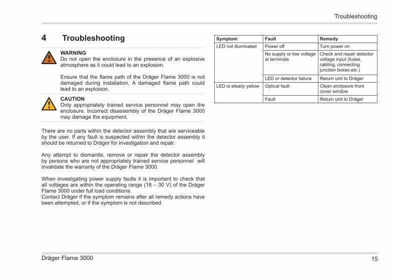
Symptom Fault RemedyLED not illuminated Power off Turn power on
No supply or low voltage at terminals
Check and repair detector voltage input (fuses, cabling, connecting junction boxes etc.)
LED or detector failure Return unit to DrägerLED is steady yellow Optical fault Clean enclosure front
cover window
Fault Return unit to Dräger
16 Dräger Flame 3000
5 Maintenance
WARNINGDo not open the enclosure in the presence of an explosive atmosphere as it could lead to an explosion.
Ensure that the flame path of the Dräger Flame 3000 is not damaged during installation. A damaged flame path could lead to an explosion.
CAUTIONOnly appropriately trained service personnel may open the enclosure. Disassembly of the Dräger Flame 3000 by unauthorized personnel is not permitted and may damage the equipment.
Any attempt to dismantle, remove or repair the detector assembly by persons who are not appropriately trained service personnel will invalidate the warranty of the Dräger Flame 3000.
There are no parts within the detector assembly that are serviceable by the user. The only servicing requirements are to inspect and clean the enclosure front cover window and functional test the Dräger Flame 3000. Dräger recommend that these tasks be completed every six months.
The actual level of maintenance required is dependant on the operating environment and the likelihood of damage or the rate of contamination from oil, etc. It is advisable to regularly review maintenance reports and adapt the maintenance period to the operating environment.
Periodic maintenance checks should be performed in accordance with appropriate codes of practice or local regulations.
!
!
1. Take the Dräger Flame 3000 offline and inhibit any associated alarms.
2. Inspect the mounting arrangements, cables and glands and the enclosure. Ensure that they are secure, correctly assembled and undamaged.
3. Clean the enclosure front cover window with a mild detergent solution and soft cloth until it is free from all contamination. Thoroughly rinse the window with clean water and dry with a lint-free cloth.
4. Test the Dräger Flame 3000 using a flame simulator (refer to the flame simulator instructions for details; Dräger recommend the Dräger FS-5000). The status LED will turn red when it detects the simulated flame.
5. Reinstate the Dräger Flame 3000 into service.
Maintenance

17Dräger Flame 3000
Disposal
6 DisposalWhen required, dispose of the Dräger Flame 3000 in accordance with national or local regulations for waste disposal.
6.1 Disposal of electrical and electronic equipment
EC-wide regulations for the disposal of electrical and electronic equipment, which have been defined in the EU Directive 2002/96/EC and in national laws, are effective from August 2005 and apply to this device. Common household appliances can be disposed of using special collecting and recycling facilities. However, as this device has not been registered for household usage, it must not be disposed of through these means. The device can be returned to your national Dräger Safety Sales Organization for disposal. Please do not hesitate to contact Dräger if you have any further questions on this issue.
Sub-components of the Dräger Flame 3000 that can be returned to Dräger for disposal are indicated by a crossed out wheeled bin symbol.
18 Dräger Flame 3000
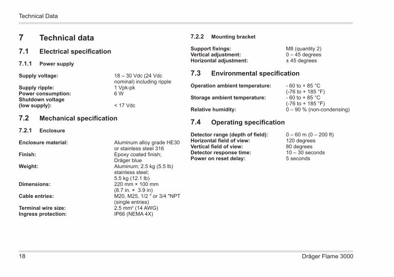
7 Technical data7.1 Electrical specification
7.1.1 Power supply
Supply voltage: 18 – 30 Vdc (24 Vdc nominal) including ripple
Supply ripple: 1 Vpk-pkPower consumption: 6 WShutdown voltage (low supply): < 17 Vdc
7.2 Mechanical specification
7.2.1 Enclosure
Enclosure material: Aluminum alloy grade HE30 or stainless steel 316
Finish: Epoxy coated finish; Dräger blueWeight: Aluminum; 2.5 kg (5.5 lb)
stainless steel; 5.5 kg (12.1 lb)Dimensions: 220 mm × 100 mm (8.7 in. × 3.9 in)Cable entries: M20, M25, 1/2 " or 3/4 "NPT (single entries)Terminal wire size: 2.5 mm2 (14 AWG)Ingress protection: IP66 (NEMA 4X)
7.2.2 Mounting bracket
Support fixings: M8 (quantity 2)Vertical adjustment: 0 – 45 degreesHorizontal adjustment: ± 45 degrees
7.3 Environmental specification
Operation ambient temperature: - 60 to + 85 °C (-76 to + 185 °F)Storage ambient temperature: - 60 to + 85 °C (-76 to + 185 °F)Relative humidity: 0 – 90 % (non-condensing)
7.4 Operating specification
Detector range (depth of field): 0 – 60 m (0 – 200 ft)Horizontal field of view: 120 degreesVertical field of view: 80 degreesDetector response time: 10 – 30 secondsPower on reset delay: 5 seconds
Technical Data

19Dräger Flame 3000
8 Order list
8.1 Dräger Flame 3000 variants
Order list
Description Part number
Single M25 cable entry, aluminum 420 94 60Single M20 cable entry, aluminum 420 94 62Single 3/4 NPT cable entry, aluminum 420 94 64Single 1/2 NPT cable entry, aluminum 420 94 76Single M25 cable entry, stainless steel 420 94 68Single M20 cable entry, stainless steel 420 94 70Single 3/4 NPT cable entry, stainless steel 420 94 77Single 1/2 NPT cable entry, stainless steel 420 94 74
8.2 Accessories
Description Part number
Dräger FS-5000 420 93 07

Draeger Safety UK LimitedUllswater CloseRiverside Business ParkBlythNorthumberland NE24 4RGTel +44 1670 352891Fax +44 1670 544475www.draeger.com
3360572© Dräger Safety UK LimitedEdition 02 – July 2012Subject to alteration
US Distributor: Draeger Safety, Inc.101 Technology DrivePittsburgh, PA15275-1057USATel +1 412 787 8383Fax +1 412 787 2207www.draeger.com