Embed Size (px)
Citation preview

Work End Of Master
MODELING OF A TELEMATIC CONTROL SYSTEM FOR ROBOTIC EQUIPMENT (SICTER)
---------------------------------------------------------------------------- MODELING OF A TELEMATIC CONTROL SYSTEM FOR ROBOTIC
EQUIPMENT (SICTER)
Author
GERMAN CARRO FERNANDEZ Economist and Technical Engineer in Computer Systems
Director:
Dr. MANUEL-ALONSO CASTRO GIL
Co-Director
Dr. FRANCISCO MUR PÉREZ
Paper presented at the
DEPARTMENT OF ELECTRICAL AND ELECTRONICS ENGINEERING AND CONTROL
SCHOOL OF INDUSTRIAL ENGINEERS NATIONAL UNIVERSITY FOR DISTANCE EDUCATION
as part of the requirements for obtaining Grade on Master on Research on Electrical and Electronics Engineering and Industrial
Control 2012 Itinerary in Telematics Engineering

2

3
DEPARTMENT OF ELECTRICAL AND ELECTRONICS ENGINEERING AND CONTROL
SCHOOL OF INDUSTRIAL ENGINEERS NATIONAL UNIVERSITY FOR DISTANCE EDUCATION
Work End Of Master
MODELING OF A TELEMATIC CONTROL SYSTEM FOR ROBOTIC EQUIPMENT (SICTER)
-------------------------------------------------------------------------------- MODELING OF A TELEMATIC CONTROL SYSTEM FOR ROBOTIC
EQUIPMENT (SICTER) Author:
GERMAN CARRO FERNANDEZ
Economist and Technical Engineer in Computer Systems Director:
Dr. MANUEL-ALONSO CASTRO GIL
Co-Director:
Dr. FRANCISCO MUR PÉREZ
Evaluation Committee:
Dr. GABRIEL DIAZ ORUETA Dr. JOSE CARPIO IBÁÑEZ Dr. ALFONSO CONTRERAS LÓPEZ
Rating: HONOURS (10) Date: 09/10/2012 UNESCO Code: 120314, 331115

4

5
Contents Acknowledgements Page 7
List of figures Page 9
List of Tables Page 11
Glossary Page 13
Summary Page 15
Summary Pág. 17
I. Introduction Page 19
II. The importance of modelling define Page 21
A) Definition of objectives Page 21 B) Integration Environment Study Page 23 C) Analysis of Robotic Equipment Page 25 D) Implementation of the system hardware and software Page 27 E) Testing and system settings Page 29 F) System Maintenance Page 32
III. Implementation of a coherent system Page 33
IV. Modeling efficiency starts with putting in practice Page 35
1. Defining objectives Page 35 2. Study of the integration environment Page 36 3. Robotic equipment Analysis Page 37 4. Implementing hardware and software system Page 39 5. Testing and system settings Page 45 6. System Maintenance Page 59
V. Estimated time system implementation based on the level of difficulty of the environment Page 65
VI. Conclusions Page 69
VII. Future work and trends Page 71
References Page 75
Curriculum vitae Academic Dossier Page 81
Annex. CD Contents Page 87

6

7
Acknowledgements
The author is grateful for the opportunity to do this work at Máster on Research on Electrical and Electronics Engineering and Industrial Control, directed by the Department of Electrical and Electronic ETSII UNED, and especially to the director of this paper Manuel Castro, Gabriel Diaz and Francisco Mur as coordinators of the subjects "Industrial applications of communications and optical systems", "Education Technology in engineering" and "Process Simulation" and "Information Security and Data Communications" for the advice and guidance received for processing.
At the same time the author is grateful to Ramón Carrasco for the cession of Spykee
robot used for the preparation of this paper, the Spanish Chapter of the Education Society (IEEE Education Society Chapter of Spain) and especially its Past President Inmaculada Plaza, the IEEE Student Branch at the UNED (IEEEsb UNED), the IEEE Foundation, and Karbo School as all of them have been worked, and continue to collaborate in this work that does not remain only on paper and it brings to the reality where is what really gives meaning to engineering. Everyone with their support, enthusiasm, motivation and financial aid are making sense of what was initially an attempt to improve, where possible, industrial technologies, and what was a grain of sand is becoming, thanks to them, on a tangible project.
Furthermore the author is also grateful to Sergio Marin and Elio Sancristobal the
advices received along this journey, that never have fallen on deaf ears, also to the authors of the information extracted from existing internet forums and users, all the information provided and has helped to better understand the features of the Spykee robot, enabling faster deployment time, otherwise and since there is no manufacturer support, would have greatly elongated.
Last but not least, the author acknowledges the support of his family, his parents
German and Julia and his sister Marta, but above all and especially to his wife Estela, patience over the years that she has had (and will have), because without their support, encouragement, suggestions, criticisms and ideas, the author never have got here.

8

9
List of figures Figure 1. The control system acts as a black box to the user Page 19 Figure 2. Relationship Objective-Communications-Environment Page 23 Figure 3. Integration process with other robotic equipment and human beings Page 24 Figure 4. Knowledge about Robotic equipment Page 27 Figure 5. Implementation of new hardware and software necessary Page 29 Figure 6. Feedback process Page 31 Figure 7. System Maintenance Page 32 Figure 8. Cycle of System Modeling Page 34 Figure 9. Robot configuration on the router by adding their MAC (Numbers have been distorted by security) Page 36 Figure 10. Source code of connection functions Page 41 Figure 11. Source code of motion functions Page 42 Figure 12. Source code of camera functions Page 43 Figure 13. Source code of sound functions Page 43 Figure 14. Source code of functions to interaction with charging dock station Page 44 Figure 15. Locate the application icon Page 46 Figure 16. Main screen Page 47 Figure 17. Screen device control via Page 48 Figure 18. Press "Connect" Page 49 Figure 19. Connection Dialog box Page 50 Figure 20. Press "Connect" Page 51 Figure 21. Robot Full Activation Page 52 Figure 22. Connection error warning and indication of error in the data from the host or port Page 53 Figure 23. Different moments of robot motion Page 54 Figure 24. Access dialog box of sound effects Page 55 Figure 25. Press sound "Alarm" Page 56 Figure 26. Process of search, location of charging dock station, possibility of cancellation, or coupling at the charging dock station, finally Page 57 Figure 27. Press "Exit Load base" and image of exit to forward direction of the robot Page 58 Figure 28. Mobile Web access from within the application with scroll to scroll and press button "Menu" to return to the main application screen Page 61 Figure 29. Navigation on the page itself from the application Page 62 Figure 30. Access to the website from a computer type desktop or PC Page 63 Figure 31. Estimated workload for different cases of Implementation Page 66

10

11
List of Tables Table 1. Estimated Time Table Page 66 Table 2. Complete table of reference data Page 67

12

13
Glossary API Acronym of "Application Programming Interface". COM From the word "COMunications". Communication port original from
IBM PC Compatible Computer. Today refers to the RS-232 port. HTML Acronym in English of "Hypertext Markup Language". IEEE Acronym in English of "Institute of Electrical and Electronics
Engineers." LabView Abbreviation of "Laboratory Virtual Instrumentation Engineering
Workbench". LCD Acronym of "Liquid Crystal Display". LED Acronym in English of "Light-Emitting Diode". MATLAB Acronym in English of "MATrix LABoratory". PHP Currently acronym for "PHP Hypertext Pre-processor". SICTER Acronym on Spanish of "Telematic Control System for robotic
equipment". USB Acronym in English of "Universal Serial Bus".

14

15
Summary At present the use of robots has shifted from industrial to educational, training,
domestic and commercial, also becoming increasingly common to have specific needs to adapt to general robotic systems. That attitude is motivated by the quest for better economic efficiency, cost savings and a full repayment of the robotic equipment with which account.
One of the most interesting educational applications in the field of UNED is the
interaction with remote laboratories. The ability to structure activities and mechanisms for remote access to laboratory robotics student for educational practices has been the main idea that has led this work, focused on the modelling of a telematic control system of a robotic team, is considered a part of an eventual PhD oriented development.
One of the most important issues of remote interaction is the control that the
user (the student in this case) can make the robot tests, but at the same time must also be given control of the robot from the server to which it is connected in the laboratory, and finally given the state of the art must be keep in mind the use of devices and mobile terminals through which also allows this task. Reason for keeping in mind, this paper deals with the modelling of a telematic control system for robotic equipment.
This paper reflects, on the one hand, the theoretical structure of the model
approaching it from the perspective of reuse, cost savings, search functionality and economy of time, and otherwise describing the practical experience of using this methodology by employing a low-cost commercial robot that is readily available, a mobile smartphone, and use free software to demonstrate how theoretical modelling system is really working on a practical level. Something that in all Ph.D. project described above will be useful in the short term to influence further into the use of remote laboratories in addition to the system of distance learning and distributed conducted from UNED.
The work includes complete exposition of the stages of modelling and a
practical implementation phase demonstrating its performance and cost data, time and efficiency. At the same time includes a CD with complete documentation, reference documents and application source code that was used in the practical implementation of the system. It has sought to use at all times free software tools and low cost to facilitate implementation and increase efficiency. Something towards the development of the PhD project will help them adapt cited to any system, and its use and distribution by the own UNED.

16

17
Summary At present the use of robots has shifted from industrial to educational, training,
domestic and commercial, also becoming increasingly common to have specific needs to adapt to general robotic systems. That attitude is motivated by the quest for better economic efficiency, cost savings and a full repayment of the robotic equipment with which account.
One of the most interesting educational applications in the field of UNED is the
interaction with remote laboratories. The ability to structure activities and mechanisms for remote access to laboratory robotics student for educational practices has been the main idea that has led this work, focused on the modelling of a telematic control system of a robotic team, is considered a part of an eventual PhD oriented development.
One of the most important issues of remote interaction is the control that the
user (the student in this case) can make the robot tests, but at the same time must also be given control of the robot from the server to which it is connected in the laboratory, and finally given the state of the art must be keep in mind the use of devices and mobile terminals through which also allows this task. Reason for keeping in mind, this paper deals with the modelling of a telematic control system for robotic equipment.
This paper reflects, on the one hand, the theoretical structure of the model
approaching it from the perspective of reuse, cost savings, search functionality and economy of time, and otherwise describing the practical experience of using this methodology by employing a low-cost commercial robot that is readily available, a mobile smartphone, and use free software to demonstrate how theoretical modelling system is really working on a practical level. Something that in all Ph.D. project described above will be useful in the short term to influence further into the use of remote laboratories in addition to the system of distance learning and distributed conducted from UNED.
The work includes complete exposition of the stages of modelling and a
practical implementation phase demonstrating its performance and cost data, time and efficiency. At the same time includes a CD with complete documentation, reference documents and application source code that was used in the practical implementation of the system. It has sought to use at all times free software tools and low cost to facilitate implementation and increase efficiency. Something towards the development of the PhD project will help them adapt cited to any system, and its use and distribution by the own UNED.

18
19
I. Introduction When it is needed to face the automation, [1], for a specific robotic process it must
evaluate several factors, utilities, objectives, actions and monitoring the results. Currently undertakes the problem from a particular perspective and focused on the process that is considered isolated and punctual. The widespread use of robots in industry, education, home, etc.. has highlighted the need for some coordination and organization at the time of starting the integration of robotic equipment in these different areas, and the goal should be cost savings, efficiency, reducing errors in the process and maintenance and more effective and productive monitoring.
The generalization of remote laboratories, [2], and reuse of learning objects [3], in
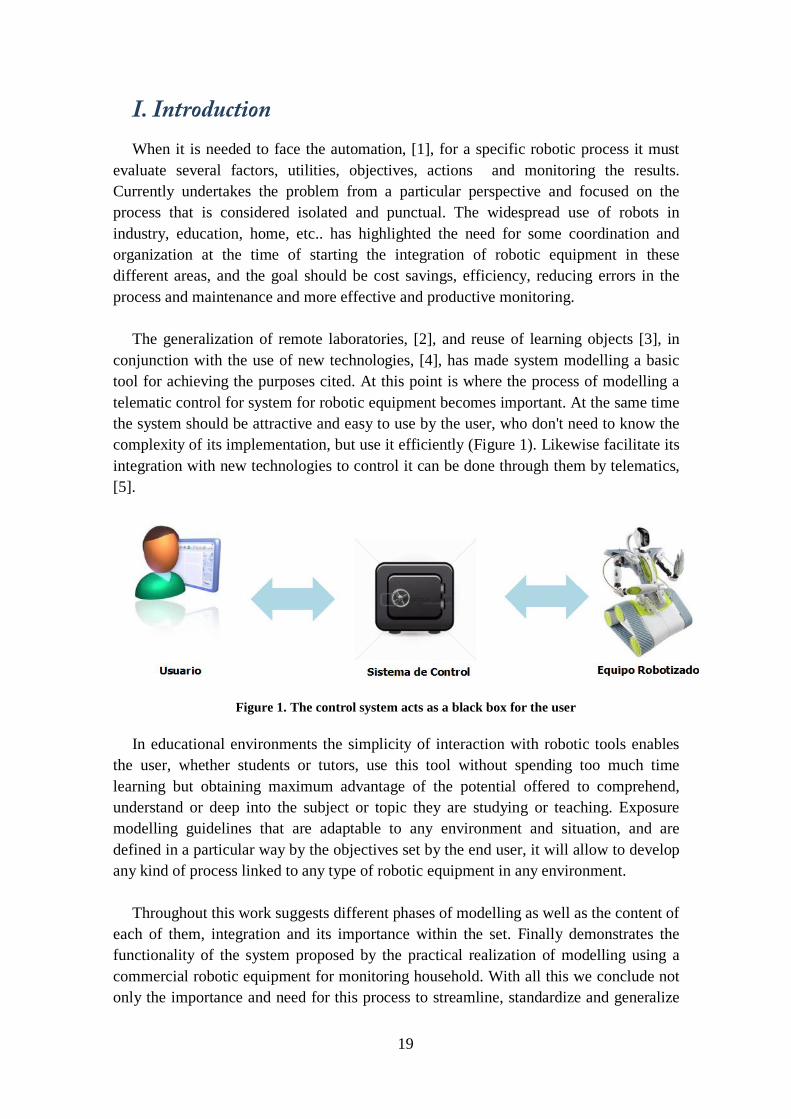
conjunction with the use of new technologies, [4], has made system modelling a basic tool for achieving the purposes cited. At this point is where the process of modelling a telematic control for system for robotic equipment becomes important. At the same time the system should be attractive and easy to use by the user, who don't need to know the complexity of its implementation, but use it efficiently (Figure 1). Likewise facilitate its integration with new technologies to control it can be done through them by telematics, [5].
Figure 1. The control system acts as a black box for the user
In educational environments the simplicity of interaction with robotic tools enables the user, whether students or tutors, use this tool without spending too much time learning but obtaining maximum advantage of the potential offered to comprehend, understand or deep into the subject or topic they are studying or teaching. Exposure modelling guidelines that are adaptable to any environment and situation, and are defined in a particular way by the objectives set by the end user, it will allow to develop any kind of process linked to any type of robotic equipment in any environment.
Throughout this work suggests different phases of modelling as well as the content of
each of them, integration and its importance within the set. Finally demonstrates the functionality of the system proposed by the practical realization of modelling using a commercial robotic equipment for monitoring household. With all this we conclude not only the importance and need for this process to streamline, standardize and generalize

20
the implementation of such systems in these sectors, but also proves to be possible to do in a short time by following a few steps.

21
II. The importance of defining modelling Proper implementation of a modelling allows optimally cover, [6], all the customer
needs, either an academic institution, an industrial, military environment or a home user with specific needs, home care, supervision and care children, elderly, sick or disabled, simple monitoring, research, etc.., and general guidelines transform a particularized system to the customer.
For this reason the developed of modelling process is divide into the following steps
which will be discussed below: a) Establishment of targets b) Study of the integration environment. c) Analysis of the robotic equipment. d) Implementation of the system hardware and software. e) Testing and system settings. f) Maintenance of the system. Each of them brings robustness and safety to the system, but at same time what give
it flexibility, something that; when we speak of technology; is necessary take into account to guarantee the system update and the team, its continued improvement and their adjustment to the needs in time. In this way, given the cost of buying a robotic equipment in environments such as industrial, medical, commercial, educational, etc.., allowed to amortize the robot to maintain its functionality in parallel to the evolution of new technologies.
A) Establishment of targets It is necessary to know the purposes for which you want to carry out the
implementation. In this case the main utility of the system is the telematic control of the robotic equipment, but this need is given by certain objectives that the client wants to achieve. Every work environment is different and the target list can be endless. It is necessary to consider the skills of the equipment, the work currently being undertaken, the usability for a new activity, or just the mere alternative use as a recycling of the same, once it is no longer profitable for the main activity played . The analysis of this point requires asking the right questions:
1. - Wok environment: not the same controlling a robotic equipment to pick up on
the conveyor belt of active surveillance robot that travels through the workplace, [7], or a robotic system intrusion detection motionless, or guide a robot that greets museum visitors, or a robot that is isolated in a laboratory and is only intended to learning sessions or predefined controlled trials, [8]. Nor is the same an industrial environment of an industrial conveyor belts and open spaces, that of a domestic environment in confined spaces with multiple obstacles, or laboratory where the robot is limited to space travel defined in advance, or an open space in which the robot has to perform simulations or rescue activities or location by land, air or sea.

22
2. - Existing Communications: in the same way be defined existing communication
systems in the work environment, benefits and disadvantages of the use of wireless systems, [9], [10], or cabled and the possible implications for interference, remote control decisions for physical cable through internet access, within the same corporate network, locally or via mobile devices or desktops, [11]. Clearly the communications and environment play a fundamental role in the physical limitations of robotic equipment. The use of this will also be decided in terms of these constraints.
3. - Objectives and utilities for your computer: must be defined in order to use the
equipment. This should indicate the performance area (a desk, a production line, the length of a conveyor belt, a rescue environment, [12], or military, water, land, air, etc..), defining the activity that is being spent on equipment (monitoring and control, security, packaging, collection, user guide, training, simulation, extraction, etc..) taking into the equipment's main activity as a priority, and valuing, in the If you want to use it for a number of activities which will be the priorities for use against the main and the importance it will have each of these on the final result.
The system is to particularize that environment and those objectives. You need to
understand that the relationship between the three factors mentioned (Figure 2) will be the basis for development of the entire system. Therefore, the developer must define them previously, with the client. A proper understanding of the final objectives, specific explanation of customer needs, establishing priorities prior to use and a clear statement of the activities to be performed by the robot equipment will help with this task.
This phase should be regarded as very important in the process, because if you
misunderstand customer needs and don't parse correctly the workplace of equipment or not referenced properly priorities for action, the other stages will lead into a system incomplete, inaccurate, or invalid. It is advisable, therefore, to devote the necessary time and properly document the final decisions at this stage to avoid misunderstandings, delays or a future cancellation of the project, even before treatment has stopped.

23
Figure 2. Relationship Objectives-Communications-Environment
B) Study the integration environment Defined the work environment can analyse the integration environment. It is defined
as the place in which the robot team must develop their work, as opposed to mere physical place that was analysed in the previous section, in this case we must deepen factors directly related to the activity to be performed:
1. - Interaction with other robotic equipments: be defined integration needs in
robotic production lines, automated transport equipment, conveyors, automated welding tools, milling services and automated cleaning robots, etc.., and wiring them all if any. Concepts such as the degrees of freedom of the equipment in question, and the extent or breadth of its radius or its arc of action, are important to avoid conflicts, duplications, noise and accidents. But in other environments to treat as training or assistance should be given to the use of other tools such as cameras, laboratory environments, testing areas, existence of interference, wireless or wired, should use in hospitals will to consider the operation of radiation equipment, frequencies, cardiovascular monitoring systems, etc.., and generally in all areas should be assessed the existence of residual frequencies caused by the use of mobile terminals nearby, lack of shielded cables, use of optical communications, among many other factors of each environment to analyse. Definitely must adapt new and existing equipment to ensure safe and efficient operation.
2. - Interaction with humans: in this case it is important to establish the conditions
under which they will present the introduction of the robot in the workplace, [13]. Avoid in any case the robotic equipment confrontation with workers, [14]. Formative mechanisms exist that will help transform the robot into a useful tool facing the worker, [14], never exclusive and always complementary [15]. In educational environments should be provided to the educator and the student's prior training new robotic tool. In both cases you should always try to integration, [16], is as quick and easy as possible, and qualifications is the best way to do this, especially when we consider the formation

24
of university students in recent years that have just, or shortly access, to the labour market, [17], [18]. Given the unpredictable nature of human beings, this section is of particular importance when there is intensive robot used by them. It is important to raise awareness of the use of the robotic equipment as a tool. Something that it is looking for help to better perform common tasks in the workplace, a new possibility to further deepen the study or learning of a subject, and as such must be specified tool which are rules of use, their characteristics, specifications, hazards (if any), and its working limits. The best in these cases is that the necessary training emphasizes safety concepts, combining practical actions with user potential oversights that may arise. Obviously never going to be able to cover all the possible variables, but allow the user to perceive the importance of proper use of robotic equipment, and learn to respect and consider it a useful tool from the beginning.
While physical integration may be problematic in the short term, by the fact define
obstacles and tools use areas, medium and long term should prevail integration with humans and that basically will be those who will interact, [19 ] with robotic equipment more directly. A leisurely explanation, clear and complete on time, [20], [21], may lengthen this phase but can provide lasting benefits and stable use of the system (Figure 3).
Figure 3. Integration process with other equipment and robotic humans
C) Analysis of Robotic Equipment This phase answers the robotic equipment depth knowledge. This requires care for
their features hardware and software. Each robotic equipment has its own characteristics. Is not possible to set new options or profits without prior knowledge and about robot skills. A proper study of its characteristics will reveal the limitations of the

25
equipment and the possibilities it offers. Within this point are due distinguish different types depending on the hardware and the software used.
1.- Hardware a) Hardware owner: usually the robotic equipment supplier will provide an
instruction manual and equipment characteristics. Is advisable that facilitates also the data sheet of microprocessors used and all that information necessary to developer can implement the system coherently. If not, it should request such information as part of the implementation of the process of analysing the hardware. If safety criteria, or patent, that are not covered by the purchase of equipment or payment of maintenance will require that a technician from the supplier makes the necessary changes leaded by the developer, to ensure operation of the equipment with the control system. In last case must be taken into account the prior budget of this process and the existence of conditions for subsequent doubling of development. If you can not make the necessary changes or the provider fails to cooperate with requests for information, or the cost of the service provided is very high, it could choose to perform equipment modifications at your own risk, losing its warranty, or well, and the most recommended, use another computer in the robot to do the changes.
b) Free Hardware: cards as Arduino, [22], reflecting that the use of free
hardware can sometimes help us with the implementation of the system. Normally data sheet board is documented and accessible and there is large number of online forums and development groups that can provide information on specific implementations or hardware customization. If domestic or educational environments can be a cheaper and customizable tool than proprietary hardware. This case will allow greater flexibility and a wide range of options for including new modules and functionalities on the computer. It is the most recommended option and allows replication of changes in new equipment without incurring the problems seen in the case of proprietary hardware. Requires a greater involvement in the development process, but also greater freedom when facing it.
2.- Software a) Proprietary Software: is usually tied to proprietary hardware, but not always.
Industrial robotics companies usually implement specific software for specific hardware. In such cases the documentation provided also often under patent, [23], is often very little informative. However maintenance service paid for those equipments usually include attention to custom software applications on computers. As in the previous case the developer and coach should contact vendor to implement the new software via telematic control requirements introduced by the new system. Again need to address the costs of the process, and the limitations on the information provided by the supplier. In these cases it is common the existence of specific software modules (available for purchase or rent) for the computer hardware, [24]. Also be taken into account that additional costs when defining the profitability of the system implementation.

26
b) Free Software: accessible through manuals, internet and technical forums. It
is also possible that a proprietary hardware is controlled by free software. In some cases they can even be internal forums on the website of the dealer or vendor you can swap modules for different robotic equipment, [25]. Requires greater customization work by the developer and must be closely linked to technical knowledge of computer hardware. Free does not mean it is free, but usually is a fraction of the cost of proprietary software, and in any case always easy to integrate into educational environments, educational or domestic, where the amortization of the system is measured differently to industrial valuing social aspects within the economic, [26]. At the same time if you use a community to share code or modules, the development process can be made lighter or you can simply allow improvements that otherwise would lead to a greater number of hours. The social aspects of work with free software are difficult to predict, but in the medium term may impact on better utilization of hardware base for which is being developed by the synergy of teamwork that of the associated.
In some cases it is necessary to use a combination of the factors above. As indicated
software and proprietary hardware and free in current technology are intertwined. Many times it is difficult to define each other, so it is not ruled out that they have to find a balance that will guarantee adequate efficiency in relation to the cost associated to optimize the implementation of the control system in question. Recall that the flexibility and adaptability is one of the essential factors of development of this modelling.
The more knowledge about the equipment can be purchased, the better and faster you
can proceed to the implementation of the system (Figure 4). In certain cases will require the collaboration of a multidisciplinary team to expedite this process, which will join forces, mechanical, electronic, software, etc.., so that the end result meets the customer's request. The collaborative work, distributed or not, generate a better understanding of the equipment and the system itself to develop. Eventually this would result in increased use of both. If we talk about an educational environment, the process will acquire a greater willingness to be replicated in similar environments at a lower cost.

27
Figure 4. Knowledge about robotic equipment
D) Implementation of the system hardware and software At this point it is ready to proceed with the implementation of the requirements of the
system (Figure 5). A thorough study of hardware and software, selected the equipment and tools needed to address it, and how to do it defined, you can start working directly for converting the current equipment into the equipment for compliance with predefined objectives . To do this we must also consider the two distinct areas mentioned in the previous point.
1.- Hardware: is sometimes necessary to add to the existing robotic equipment some
hardware modules to adapt the equipment to the new conditions, [27], in this case are those that facilitate communication and telematic control. To do that, choose the right components based on the needs and uses studies being done. I explained the importance of defining the use of wireless or wired systems, but also should add modules to perform the tasks related to the objectives defined, extensions to allow mobility of equipment (wheels, tracks, sliders) for collection objects (tweezers, vacuum cleaners, hooks, magnets, pressure sensors) for visualization and control of environments (cameras, motion sensors, temperature), communication (sound card for sending and receiving audio, audible alarm enable , hazard or warning systems, LED or LCD display to show or receive data, external keyboard, USB, COM), etc. in short everything necessary to set in software after the previously stated objectives. Also, in the case of hardware owner must take into account compatibility to integrate systems. This compatibility is usually defined in advance by the manufacturer, but if not, should be known prior to the addition of the new modules in the robot team.

28
2.- Software: code implementation to develop the environment for communicating the system, [15], reply to the use, in each case, appropriate programming language, [10]. Environments owners offer their own programming language more or less adapted: Parallax PBASIC, KUKA Software, Software Lego Mindstorm based on LabView for Lego, [28], Microsoft Robotics, etc. Related to open source environments common languages used in their implementations: MATLAB, URBI, JAVA, C, C++, Python, even assembler in some cases. A very important part of this section is to interrupt handling and proper implementation of the error messages. The correct treatment of these allow adaptation and correction system much more quickly and safely. Another recommendation here is to implement the objectives of a modular system. That will allow to add or remove features in robotic equipment depending on customer needs. Facilitate integration with other robotic equipment to apply the same modelling process, and will gain in efficiency. The software implementation of the proper use of comments in each of the phases of the same, and proper organization of the modules, libraries and functions that are used during development, will allow future changes, improvements and maintenance are performed in the best possible way and as quickly. Since the objective is to reuse and efficiency, information on how it was done the first implementation of the system should be properly documented, modularized, organized and tidy.
In any case prior to final assembly, or even own software implementation, you can
use simulation programs, [29], to check if the changes to be made are effective and comply with the defined objectives and the way you want, or if you need further adjustments, or if it has been overlooked variable in the environment or in the configuration of the computer, which should count or requiring changes to the overall system approach. Some programs, such as Webots, are oriented specifically to educational environments in its basic version, free of charge, with an extensive library of PC computers simulated robot for testing them (Nao, Aibos, Bioloids, Boe-Bot, e- puck, HOAP-2, iRobot Create, Katana, Kheperas, Koala, Kondo KHRs, etc.), [30], others as COSIMIR, CIROS, ARENA Simulation or Flexsim is used to play robots and industrial environments or fully customized industrial, [10]. In both cases, allows the import of custom robots from software design and modelling of such objects Autocad, SolidWorks, Blender, 3D Studio Max, etc. It is not always necessary but, to certain systems complex, the previous simulation facilitates the implementation, increasing efficiency and saving development costs.

29
Figure 5. Implementation of new necessary hardware and software
E) Testing and system settings Once implemented the hardware and software of the highest priority telematic
control focuses on testing and performance testing. It is need to check that all work performed meets the expectations expected. This point is particularly an important documentation of the previous steps, you can locate good documentation errors and adjust, in a faster and more efficient. Tests should be adjusted based on the stated objectives. If possible should be done with the future user of the system to enable it to propose possible adjustments to the interface, or suggest situations that have not been considered previously in the previous phases. Continuing with the case in question, telematic control can serve different options, some of which are listed below:
- Education and training: Full computer use remotely, either from within the
Intranet, or the Internet anywhere in the world. In this case requires that the functionality of the equipment is as complete as possible to pupils/students can learn to control the team as a whole, [31], or at least learn to work with software development needed in each case , [32]. In a situation of this kind play an important role the security, controlling and monitoring the implementation of the system. Current technology has many tools to ensure proper access to the system by the user and authorized personnel, but at the same time should be to find a balance between the difficulty of the access interface and delays for data validation and exchange and security risks in the system. It is always recommended that ensure maximum security, and if necessary, adapt a custom interface for the user. It is recalled that in this work what is looking for is that the system acts as a black box between the user and the robot team, bringing the final objectives must be achievable keeping that premise throughout the modelling. If at some point in development this goal has faded, the timing is perfect for back to it before finalizing the development of the system.
- Monitoring and supervision: Using motion sensors, adjustment thereof, camera
control, movements of them, etc. all guided remotely by accessing local or remote

30
telematic. For assistance or care of children, elderly or infirm inclusion and control of sensors to measure the patient's temperature, neuronal frequency control, cardiovascular calibration, etc., should be part of these tests to minimize false positives , but mostly false negatives, since at stake is the life of people. Again direct application on the end user is essential to check the correct operation of the system. Simulators can be used for diagnostic or simply perform field tests with healthy subjects to take test data, in any case given the importance of these services not only have to take into account the very security of the system, but the effectiveness of same. While you are using a previous software has been adapted to improve or increase services robotic equipment, you must check that the final results are ensuring that the efficiency equipment had before the changes have been made, if you have not managed to improve this.
- Interaction voice or audio: On the case of guide robots, [33], [34], in which the
need for greater interaction with the user, you need to check if the transmit and receive audio are consistent and not interfered. At the same time we must analyse the end-user response, if the movements, expressions or the actual route of the team is right and expected, if the interaction with humans runs the service that is right, and if the team is prepared for possible problems that may occur in this interaction: hitting or tripping of users, problems in system power, spill liquids on its surface, handling enabled touch screens purpose. At the same time you should check if the data load is simple enough for users of the work environment, if you meet the defined expectations to start modelling or if further adjustments are necessary.
- Other specific features: given the versatility of the system modelling, this
includes the rest of the functionality required by the client and been exposed to the initial objectives of the process, including possible domestic utilities if that is the case [35]. Also the combination with other skills such as those required for rescue in hazardous areas or war, the joint use of electricity services in environments fuel or air, sea or land, the use of equipment such as cargo transportation system, among many others. The testing phase will verify compliance with the limits established service and provided environmental conditions, such as volume data load, temperature of operation, data acquisition levels in the sensors, adaptation to the environment, etc., Should defined finish at this stage to terminate the previous deployment work by the robotic equipment included with the new settings.
Previous deployment spoken because this section responds to a continuous feedback
process (Figure 6) which aims to achieve greater efficiency in the actions to take and check the operation of hardware and software system in all cases requested (or at least for most of them). Included, of course, verification and management of errors and interruptions that have already been taken into account the planning and implementation of the software, subjecting the robotic team to situations where there is a known error procedure scheduled let you know if the answer is desired and if the notice to the user is correct and understandable by it (a warning or alert screen, a red light flashes, an audible warning, a mixture of them all, etc..). Also reviewing the use of servos, LED

31
lights, audio alerts, cameras, speakers, microphones, systems maintenance, batteries, remote charging bases, etc., should be tested as part of this phase, as software and hardware must be properly integrated to ensure proper operation.
In a system of telematic control the robotic equipment must be able to manage
themselves as necessary (interruption of communications, electrical power failure, lost connection to the control system, etc..), but should also allow the user to Full remote control (send activation order or stop, launching batteries recharge warning, move the equipment to a safe area in case of failure, etc..), so it is recommended to test the largest number of events and possible events during this phase . Once it achieved the desired results may be concluded that the system meets the objectives and is ready to be used widely.
Figure 6. Feedback process
F) System Maintenance Finally, the modelling should allow the fitted, flexibility and adaptation of the system
over time and to different changes in its environment. Following the previous guidelines, will ensure that, this being a cyclical process, a minor change in the objectives or the environment will require minor modifications to the hardware or software, and almost no change in the implementation of telematic control . More drastic changes will mean significant changes conditions in hardware and software but may cause small changes in the telematic control. Only an important transformation of communications force us to modify our telematic system. However, and even then, given the experience of the first implementation of the system modelled, times, costs and delays motivated by this new situation, always be lower with this modelling process, that is suffer in the same situation if it does not exist.
Generally system maintenance should be parallel to the increase in the functions of
robotic equipment. Compliance with the recommendation of modularity facilitates this process. Regarding the work already in place, the operator or the customer may receive any malfunction or improper system if it has respected the implementation phase aforementioned error. The aim is to facilitate the interaction with the robotic system to those who do not have to possess advanced technical knowledge about the equipment. At the same time will keep your computer updated delaying obsolescence, allowing

32
higher amortization of the same, which is beneficial for the sustainability of the system (Figure 7).
Figure 7. System Maintenance

33
III. Implementation of a coherent system As shown in this work is necessary to implement a system coherent with the needs
reflected in the modelling, but at the same time the system has to meet some basic features that have gone ahead:
1.- Flexibility and adaptability: the system must be able to adapt to new needs. This
process must be performed without excessive adjustment costs and if possible in an agile way.
2.- Modularity: setting hardware and software modules provide flexibility,
maintenance and correction of the system as necessary. At the same time provide the possibility of replication saving costs in the process.
3.- Simplicity: the system must be understandable and facilitate their supervision by
unqualified personnel. Proper implementation of warnings and errors is essential for this feature to be fulfilled. A proper GUI can help whenever possible.
4.- Functionality: objectives must be met initially exposed in modelling. As already
mentioned, they must be clearly defined and which form the basis of the system. 5.- Efficiency: is better to stick to concrete and achievable objectives that generalist
objectives that complicate the implementation to the point of damaging the ease of use or limit the functionality and flexibility.
6.- Economy: used as modelling tools and adapting existing equipment and to
facilitate their control by computer, the result of implementing the system will be less expensive and thus more economical.
Modelling, which has been exposed along this work, corresponds to a cyclic
evaluation system is fed in each phase (Figure 8), but it is in the test phase and system settings where that feedback is more important and is more visible. Supports each stage to the next, hence the importance of moving forward progressively, without jumps, and devote adequate time to each. In general the early stages ("Definition of objectives" and "Study of the environment") require a more intensive time commitment as it is necessary to know what is to be achieved and what is the starting situation presented at the beginning of the process .
The next steps ("Analysis of robotic equipment" and "Hardware and Software
Implementation") are more labour intensive and require a higher burden of specialization because it is necessary to know thoroughly the equipment before proceeding to make the necessary changes on it.

34
Finally the last stages ("Tests and Adjustments" and "Maintenance") use multiple factors to ensure on the one hand that the desired system works and that its maintenance will be adjusted to the needs temporarily.
Figure 8. System Modelling Cycle Importantly, the relationship between the phase of "Tests and Adjustments" and
the "Definition of objectives." As can be seen are closely related, so much so that if in the testing phase we see that something is not working or responding as expected initially, it may be necessary to redefine the initial objectives and modify previous work, resetting the system .
The modelling can manage a complete system that is evolving and is fed. The
explanation is trivial, in a market like robotic equipment, software and communications, you need to be updated. Changes occur very quickly in a very small time interval, so that if the development or implementation of the system are extended longer than anticipated, it may be necessary at first to update the system, something that will be addressed in the analysis of time that takes place in the same work.

35
IV. Modelling efficiency begins with its implementation Using a modelling systems to stay in the theory and no allow measures in practice
the real possibilities of implementation it is not useful. That is the reason that the modelling described in this work has been to reality. This section will analyse step by step each of the sections listed above and their implementation time and problems encountered during the development. This shows that the system works in practice statement. It should be emphasized that the application developed is a for educational use. It has served the graphic design versus functionality, because the objective is merely academic and demonstrative, and not commercial. It is clear that real development should take care both functionality and visual appearance or commercial development in question.
1. Definition of the objectives In this case the aim is to study the telematics control implementing on commercial
robot. Robotic equipment comprises a robot model from Mecano company, namely Spykee, [36]. For this, the following definitions applying:
Work environment:
o Domestic use for surveillance, which involves travel surveillance area, area monitoring in real time by camera, issuing warning notices.
o Common obstacles in an address, carpets, furniture, walls, doors, etc.. Existing Communications:
o Router Wi-Fi standard, personalized and password-protected transmission WPA and MAC definition. Wi-Fi receiver's own robotic equipment compatible with standard commercial systems.
Establishing control objectives. o Remote connection equipment via smartphone, Andoid operating
system electronically, initially in local mode. o Use of the following equipment features: motion, Wi-Fi, making
sounds, live webcam, automatic search the charging dock station. o User controlled advance, except in the case of the automatic search of
the dock station.
With the above analysis has been defined the starting point and objectives. The following steps will enable to know the possibilities pf the equipment and whether or not carrying out such unrealistic objectives, or what changes are necessary to do so.
2. Study of integration environment Unlike the previous section will be discussed in this case the interaction with the
basic elements of the surroundings: Interaction with other robotic equipment:

36
o In this case there are not other robotic equipment that may affect the direct operation of the robot.
o There are household machines whose operation can be issued with residual frequencies as televisions, computers, etc.., However the interference are standardized and its effect should not be problematic.
o The use of other equipment such as vacuum cleaners, and other wired of the home, recommend establishing a proper camera angle to avoid obstacles during the telematic control.
o Proceed to configure the router home with the respective data of robotic equipment to verify proper operation of this (Figure 9) with established safety conditions usually in the router . The router is a model COMTREND ADSL Router with software version A111-306TLF-C02_R16 and driver version Wireless 4.150.10.5.cpe2.0.
Figure 9. Configuration of the robot into the router adding its MAC (numbers
have been distorted for security)
Interaction with humans: o Since the team is oriented to surveillance is difficult to produce a
human interaction during the current operation. However because the control is performed by the user, the same recommendation that has been established for wiring elements is indicated in the event of humans in the path of the robot during its service.

37
Defined the environment should be addressed technical study and evaluation of the
possibilities of implementing the system.
3. Analysis of Robotic Equipment It should at this point make the analysis of hardware and software with account, prior
to the implementation process. Equipment hardware analysis: It consists of the robotic equipment itself
capable connection via Wi-Fi, webcam, sound emission and reception of real-time activity via LED light, and movement.
o Proprietary Hardware: PCF50633 Phillips uses for power control and load of battery, the motherboard is based on the CNX 111 WaveStorm with 200MHz ARM9 processor with 802.11b, 802.11g and USB2. The biggest problem is that the manufacturer of this board no longer exists, is not supported on it and there are no references to data sheet which can clarify the operation of it. On the other hand the working voltage pin serial connector of the equipment, with features 38400 baud 8-N-1 and J2 connector: TX | RX | GND; works at 3.3 volts, so if is need to attack the board should be to use an adapter to avoid blowing it in the process.
o Free Hardware: No free hardware used.
As an example of one of the problems that had to be solved during this work and to show the importance of internet forums, [37], as far as concerns robotic equipment, indicates that this robot has been marketed since 2006. Initially and through the manufacturer's own software, through user registration and number Robot MAC, you could assign a name to it in the manufacturer's servers, and then using that name and the right software, the user could connect remotely to the robot from anywhere. Trying to check this service during the preparation of this paper, the system did not work. After several days of exhaustive search through the internet, and the unsuccessful sending several emails to manufacturer no response, an email found, a user who once had the same problem, as of 2009, [ 38], which clarifies that the manufacturer discontinued the service after a massive attack on its servers in 2007. Fortunately explained in the same mail, using the host Reference and through port 9001, and following the reference manual, you can also control the robot through its software, from anywhere. It has been proven that it is, and proper operation.
The above anecdote shows how important is a comprehensive study of robotic
equipment before boarding their adaptation for telematic control. As can be seen the hardware also has its secrets, and these must be discovered before starting the process, to avoid surprises and weigh the possibilities, feasibility and costs of modifications required in each case.

38
Equipment Software Analysis: o Proprietary software: The control software is distributed freely. No
specific software for telematic control via smartphone by the manufacturer. However there is a private company that develop applications for smartphone, which distributes prepaid software for this, [39], breaking with the open source philosophy that advocates the robot manufacturer. This software does not support or guarantees of any kind by the company and has not been updated in years.
o Free Software: As said the kit comes with its own software for PC control. An interactive interface to control the robot and distributed for free from the manufacturer's website, [36] . This software supports only Linux, Windows or Mac For mobile terminals via telematic control there are some isolated attempts several years ago, both for smartphone, [40], and for iPhone, [41], made by individual users, who have not led to anything concrete. Despite these efforts provide valuable information about the operation of the software, which will facilitate the work of implementing the system code.
To control the firmware the manufacturer distributes the sources to compile its own firmware via Linux. While both the code and basic instructions are distributed free, it is needed advanced knowledge of hardware and Linux to compile it. However information about functions, features, interruptions, etc., has been helpful to develop the telematic control software that has been made, [42].
No original firmware version available for the robot, and the version on the website
of the manufacturer is damaged and does not work, [43].
Given the age of the equipment most of the projects that were initiated at the time to control it, have gotten stuck, [37]. But at the time it was collected much information that has been very helpful to speed up the process of implementing the system, reducing the time needed for it. Disregarding the data sheet of the motherboard, information forums, however old it may be, and the sources of firmware, have been essential to learn more about the equipment and to implement successfully the robotic system.
4. Hardware and software implementation. Once you know the equipment is going to determine what you need and what
changes should be made to adapt and achieve the desired objectives: Hardware: Since the material and components used spare no possibility today, it
establishes the premise of using what already exists on the equipment with the least possible handling in it. Only in the event that this does not work, we propose to add modifications using free low cost hardware, such as Arduino boards. In this case the robotic equipment preparation requires only follow the assembly instructions of it, which facilitates free by the manufacturer, [42]. The

39
process is simple and is a step by step from the testing of the materials that make up the equipment to the stages of assembly.
Software Established the no modification of the hardware, the implementation turns in using the software as a basic tool for adjustments and changes. It examines each of the objectives and implementation of code performs required to access the functionality to carry them. This process has been performed using an environment with Windows 7 Operating System, [44], 64 bits on a desktop computer with 4 GB of RAM, Intel (R) Core (TM) 2 Quad CPU Q8300 2,50GHz. It has been used as IDE NetBeans IDE 7.0.1, [45], with JAVA jdk1.6.0_26, [46], and Android-sdk 20.0.3 with 4.0.3 Android API 15, [47]. The software has been developed in this paper is distributed for educational and demonstration purposes as free and open software with GPLv3, [48], with all that this implies for the advertising of the sources and references. Also the software mentioned can only be distributed with this work, and with the prior approval of the Department of Electrical, Electronic and Control Technical School of Industrial Engineering, UNED, and its author, as it is part the same and has been developed for a better understanding of it.
o Connection: It is the most important part of the system. Given the existence of an internal Wi-Fi node in the equipment, it has been used to connect to it. For this we have followed the same process used in the original equipment software. From the analysis of the firmware it decides to use several functions in Java to manage the connection. First launches package IP access to which is connected the robot, after receiving the response is sent login information and password and, if correct, access is allowed and jumps into activating robot. One can appreciate the Java code that gives rise to the functions managing this service (Figure 10). If at any time there is a connection error, the screen will display the reason for it.

40
//Connection Manager with the robot public void connect(String host, int port, String login, String password) throws UnknownHostException, IOException { Log.d(TAG, "connecting to " + host + ":" + port); mSocket = new Socket(host, port); mOutput = new DataOutputStream(mSocket.getOutputStream()); mInput = new DataInputStream(mSocket.getInputStream()); sendLogin(login, password); readLoginResponse(); startNetworkReaderThread(); } /... .../ //Send the login and password data private void sendLogin(String login, String password) throws IOException { int len = CMD_LOGIN.length + login.length() + password.length() + 3; byte[] bytes = new byte[len]; System.arraycopy(CMD_LOGIN, 0, bytes, 0, CMD_LOGIN.length); int pos = CMD_LOGIN.length; bytes[pos++] = (byte) (login.length() + password.length() + 2); bytes[pos++] = (byte) login.length(); System.arraycopy(login.getBytes(), 0, bytes, pos, login.length()); pos += login.length(); bytes[pos++] = (byte) password.length(); System.arraycopy(password.getBytes(), 0, bytes, pos, password.length()); showBuffer("send", bytes, bytes.length); sendBytes(bytes); } //Return the response to the login sent private void readLoginResponse() throws IOException { byte[] bytes = new byte[2048]; int num = readBytes(bytes, 0, 5); showBuffer("recv", bytes, num); //The fifth byte is the number of bytes remaining to be read int len = bytes[4]; num = readBytes(bytes, 0, len); showBuffer("recv", bytes, num); if (len < 8) { return; } int pos = 1; int nameLen = bytes[pos++]; String name1 = new String(bytes, pos, nameLen, "ISO-8859-1"); pos += nameLen; nameLen = bytes[pos++]; String name2 = new String(bytes, pos, nameLen, "ISO-8859-1"); pos += nameLen; nameLen = bytes[pos++]; String name3 = new String(bytes, pos, nameLen, "ISO-8859-1"); pos += nameLen; nameLen = bytes[pos++]; String version = new String(bytes, pos, nameLen, "ISO-8859-1"); pos += nameLen; if (bytes[pos] == 0) {//Detec if robot is on dock station or not mDockState = DockState.DOCKED; //On dock station } else { mDockState = DockState.UNDOCKED;//Out of dock station } Log.i(TAG, name1 + " " + name2 + " " + name3 + " " + version + " docked: " + mDockState); }
Figure 10. Source code of switch functions

41
o Motion: In the task of security is necessary to ensure the movement of the robot for the workspace. This is implemented for controlling the robot towards the directions front, back, left and right through the emission of pulses for better control. As in the previous case is also shown the relevant code (Figure 11).
//Management of robot movement public void moveForward() { //Hacia adelante mCmdMove[5] = (byte) mForwardSpeed; mCmdMove[6] = (byte) mForwardSpeed; try { sendBytes(mCmdMove); stopMotorAfterDelay (300); //Breaks movement of 300 milliseconds } catch (IOException e) { } } public void moveBackward() { //To back mCmdMove[5] = (byte) (255 - mBackwardSpeed); mCmdMove[6] = (byte) (255 - mBackwardSpeed); try { showBuffer("moveBack", mCmdMove, mCmdMove.length); sendBytes(mCmdMove); stopMotorAfterDelay (200); //Brak movements of 200 milliseconds } catch (IOException e) { } } public void moveLeft() { //To left mCmdMove[5] = (byte) (255 - mTurningSpeed); mCmdMove[6] = (byte) mTurningSpeed; try { sendBytes(mCmdMove); stopMotorAfterDelay(200);//Break movements of 200 milliseconds } catch (IOException e) { } } public void moveRight() { //To right mCmdMove[5] = (byte) mTurningSpeed; mCmdMove[6] = (byte) (255 - mTurningSpeed); try { sendBytes(mCmdMove); stopMotorAfterDelay(200);//Break movements of 200 milliseconds } catch (IOException e) { } }
Figure 11. Source code of Motion Function
o Webcam: It provides visualization functionality via webcam in real
time as a tool of surveillance task to perform. That will also help to control the movement of the robot on an environment with obstacles without problem. Shows the code that handles the display of the camera image in real time (Figure 12).

42
//Start the camera public void startVideo() { try { sendBytes(CMD_START_VIDEO); } catch (IOException e) { } } //For the camera public void stopVideo() { try { sendBytes(CMD_STOP_VIDEO); } catch (IOException e) { }
}
Figure 12. Source code of Camera Functions
o Sound: It used several warning signs that the equipment itself has by default on its system. These signals will be useful to indicate a warning or just to check that the system works properly. The code below shows the available audio options (Figure 13).
//Start the audio public void startAudio() { try { sendBytes(CMD_START_AUDIO); } catch (IOException e) { } } //For the audio public void stopAudio() { try { sendBytes(CMD_STOP_AUDIO); } catch (IOException e) { } } //Sounds the Alarm public void playSoundAlarm() { mCmdSoundEffect[5] = 0; try { sendBytes(mCmdSoundEffect); } catch (IOException e) { }
} /... Other signals related .../ //Make Robot noise sound
public void playSoundRobot() { mCmdSoundEffect[5] = 5; try { sendBytes(mCmdSoundEffect); } catch (IOException e) { }
}
Figure 13. Source code for sound function

43
o Autonomous charged: In the robot software is possible the autonomous search for the charge dock station when battery is low. This same system has been used together with the actual data load at every time. Once load levels show values below 10%, or at any time of use, it allows the user to send the robot automatically charging order, which activates the automatic search of dock station by infrared sensors, and directs the robot to proceed to the charge. These functions activate the search option and start charging the robot (Figure 14).
//Set the robot to fly out from dock station public void activate() { if (mDockState == DockState.DOCKED) { undock(); } startVideo () ; //Start the camera startAudio () ; //Start the audio setVolume (DEFAULT_VOLUME) ; //set the default volume } //Send the order to return and seek dock station public DockState getDockState() { return mDockState; } // Status 'charging' public void dock() { try { sendBytes(CMD_DOCK); mDockState = DockState.DOCKING; } catch (IOException e) { } } //Status 'not charging' public void undock() { try { sendBytes(CMD_UNDOCK); mDockState = DockState.UNDOCKED; } catch (IOException e) { } } //Cancel charging public void cancelDock() { try { sendBytes(CMD_CANCEL_DOCK); mDockState = DockState.UNDOCKED; } catch (IOException e) { }
}
Figure 14. Source code interaction functions with charging dock station
After the installation and implementation of the equipment, it must perform the preliminary operational checks. It verifies that the assembly is right, performed basic tests and checks on the correct operation of the robot using the software provided by the manufacturer. This verifies that the robot is fully operational. Furthermore verifies the correct compilation of software, eliminates syntax errors that may exist and debugging

44
the code to generate the native application package to be used in the smartphone on the next phase. Once these points, it is able to enter the testing phase and final adjustments.

45
5. Tests and Adjustments Given the initial target for surveillance use, it shall carry out the relevant tests and
adjustments required for it to pass. Regarding the hardware, first turn on the robot in the dock station and connect the
LAN port to an IP address through domestic router. Since the test is to be performed on the same Wi-Fi, right after verifying the connection, and operation of the corresponding port to be used, it is the time of the software.
With regard to the application software is installed natively on the smartphone, in
this case a HTC EVO 3D X515m with Android OS 4.0.3. Once it is installed, it runs and proceed to use the menu screen to check all functions of the system in the robotic equipment:
First, access the main screen of smartphone and press the icon identifying the
application, with the image of the robot in question, and the name of it, in this case "SICTER for Spykee" (Figure 15).
Figure 15. Look for the application icon
Then it can access to the main screen of the application (Figure 16). On this screen appears only certain buttons are active. The rest only will be active

46
when the connection to the robot equipment is successful. The top legend tells the user to choose what type of robot control want to use: a) "Control via web": Take the user to a specific website on the internet, for robot control using it. b) "Control via device": Allow the user to use the smartphone to control the robot. On this case that is the option to use.
Figure 16. Main Screen Clicking on each of the buttons disappear options remaining, so that the user don't mistake while using the system. Pressing the option b) will access to the control screen (Figure 17). On it several sections are differentiate. On centre it is seen what is identified as "Camera frame" In this space it will load the camera image when the robot is activated. Below are four directional buttons. They are used to control the robot in four directions programmed: forward, back, right and left. This control is performed by discrete pulses to facilitate control of the robot. In this way the robot will move through controlled pulses, preventing connection failures causing long paths that endanger the integrity of the robot or its environment.

47
Figure 17. Screen control via device
Pressing the "Connect" button the application will attempt to contact the robot. To do this, after pressing the button (Figure 18) displays a dialogue box where you must enter the data required for connection.

48
Figure 18. Pressing "Connect" It is necessary to enter all: host, port (9000 on this type of connection), user name and password, and thus try to connect to these data (Figure 19). If control from outside the Wi-Fi, the "Host" must be completed with the web address or the DNS router it is connected to the robot. If this is so, as indicated when was describing of hardware section, the port should be 9001. On this case it is not necessary, although it is one of the maintenance options are listed at the end of this paper.

49
Figure 19. Dialogue conection box If the data are correct, pressing "Connect" (Figure 20), the robot is turned on and go away rapidly from its base with an acoustic signal.

50
Figure 20. Pressing "Connect" At that time also activate the other buttons on the screen and loads the camera image on real time, displaying all that the robot is currently watching on live (Figure 21). It is important to mention that, with proper connection to the robot, appear a legend that indicates on real-time the IP address is connected to the application, and the level of battery charge of the robot at each moment, in the range of 1 to 255, to help control the level of it.

51
Figure 21. Full activation of the robot If a connection fails, it will be displayed on screen to give users the solution (Figure 22). After correcting the error, you can try to connect again. In no time the erors into application going to cause problems of instability or close it without notice. Proper management of exceptions prevent data loss or poor use of the system, hence the importance of interruptions seen into the code of this project and on previous sections. On this case one of the warnings meets a predefined exception in JAVA which clearly indicates that the connection through host and specified port is not available because there is no network connection is available. The same applies in the case where any data from improperly fill host or the port.

52
Figure 22. Connection error warning and indication of error in the data host or port
After confirming a successful connection to the robot, you can try the different features available, beginning with the interactive and camera movement in real time. By pressing the motion seen in the camera frame as the robot moves in the direction indicated (Figure 23). It verifies that all the answers are correct. One important thing to keep in mind is the quality of the Wi-Fi connection between the node and the robot. While native application will always work correctly, the data reading can be affected by the distance to the node. This effect may lead to delays in the movement of the robot, or data incorrect readings. If the robot is away enough, it would lose the connection and the application will disconnect.

53
Figure 23. Different times of the movement of the robot

54
Following checks it can do a sound check. To do this, from the main screen,
you must press the button "Sound Effects". This will display the dialogue and sound effects let you choose one of the available there (Figure 24).
Figure 24. Access to dialog sound effects box Once chosen one it only need to press on it to issue the aforementioned robot sound (Figure 25). The sounds listed are all that comes with the robot. It has been used as a reference the original list, and like it, have left two custom options if you want to use.

55
Figure 25. Pressing the sound "Alarm"
Finally, since the robot continued use causes your battery is empty, it has also the functionality of search, location and return to the charging dock station. This requires, from the main screen, press the "Go to dock station." Then change status button and it will activate the "Cancel charge", the reason is simple. During this process, the robot will use its embedded infrared sensors, and infrared sensors and charging base are going to pair, which held circular paths until it finds the right way to go. If the battery level is very low, it may interest to cancel the process to save the little energy left over and use it to display images on the camera or to make a sound. Pressing this button will cancel the search process. If instead it lets the robot finds the dock station, it locates and head towards it. Once in a few inches of it, shall become (as the charging connectors are in the rear) and paired infrared sensors, will slow and dock it to charge. In this situation, enable "Exit to dock station" so that the user can regain control of the robot when it deems appropriate (Figure 26).

56
Figure 26. Process of search dock station, location, possibility of cancellation, or final dock into dock station

57
If finally it chooses to leave the dock station once the battery has recovered, this option can be made by simply pressing the button (Figure 27). It is interesting to note that while the robot is in the charging dock station are available sound functionalities, but the camera will only show the last frame from the last image captured, and is not available the option of moving. All of this to save battery and allow the loading of it as quickly as possible. Just out of the dock station can be recovery completely the control of the robot.
Figure 27. Pressing "Exit to dock station" and image of the exit towards of the robot The button "Off" shuts down the robot completely and removes the last image taken
by the camera, returning to the main screen of the application and making available all of its options.
Successive tests have been improving the software go through an adjustment system
based on trial and error, and small changes on the user interface of the software, based on the robot's behaviour, and clarity of the interface, to enable better understanding functions of it by the user. To verify that the software is clear enough to be used by a user without knowledge of robotic equipment or on the software implementation of it, it was used a person as test subject that in minutes has been done with the application and has successfully tested all the functionality of the robot. With this latest test was confirmed that the system acts as a black box that allows the use of robotic equipment in a consistent way, without the user having high computer skills.

58
Once this phase is considered that the system is ready to be used widely on this
environment. At that time qualifies the telematic control software as "Spykee SICTER for version 1.0" and finished the process of telematic control system development for this robotic equipment.

59
6. Maintenance However, the modelling process continues and will do so indefinitely including the
maintenance phase. On It will be monitored the system and made the necessary improvements to widespread use or adapt new hardware and features to robotic equipment, and software control, as needed or the client, or the working environment, as required.
As examples for improving the native application can be described as follows:
Improved error display on screen. Generating a video or photographic images store from the robot camera, for
later retrieval, if necessary. Improved remote connection from outside the network through the use of a
VPN system controlled. Exploiting the possibility of using custom sounds, as in the original software
for desktop terminal robot. Furthermore, on the case of study, the maintenance results in the possibility that the
computer control is performed in a completely remotely option simply by using any available Internet access. For this it will implement the following improvements to the system:
Accommodation in a commercial web server interface to the appropriate
remote access. Tests with routers domestic or via 3G connections have not shown reliable results, producing constant interruptions or making difficult the connection, probably by the proxies that use commercial networks to communicate their nodes. On the other hand the evidence shows that institutional buildings need complete access to the firewall and systems management access settings, something that usually is not allowed. Using a full web server commercial would avoid these problems and allow for a full configuration to permit its use without problems.
Creating a website for mobile terminals. It is used JQuery Mobile to facilitate integration with mobile terminals.
Creating a website for desktop PC or standard laptops. It uses standard jQuery and other web development languages.
This web server manages through automatic redirection, access to it of standard or mobile terminals, leading each of them to the website that corresponds to a correct view of the same in each case.
Access from within the native application software to a web server. When access is made from the specific section of the software on the mobile terminal, the load that occurs is the web page for mobile terminals. Nevertheless, if you do not use this service, you can access the general web

60
site if necessary. (Figure 28). At web site that is accessed from within the application, through the "Control via web" of it. This opens a new screen where internal application through a frame loading the embedded web page, giving the effect that you are not working outside the application. It can browsing the web using the option scroll that is enabled in the application. When it wants it can return to the main screen of application by pressing the "Menu". The process is completely transparent for the user and allow the user to use the system as he/she wants, depending on one's needs to be present at all times.

61
Figure 28. Mobile Web access from within the application with scroll to browse and press button "Menu" to return to the main screen of the application

62
In the same way it can browse the web and use the "Back" button on the bottom left, or enabled on the web, to browse through pages visited (Figure 29.).
Figure 29. Browsing on the page, from the application If it desired access terminal through a desktop, or laptop, or any non-mobile terminal, the server address http://www.robot.warningcorp.com redirected to the website set up for this purpose (Figure 30.). On this case, the web would travel through the different tabs above ("Help", "Movement", "Camera", "Access and user" and "About the author") finding information on how to use the web in each case. To control the robot it would use the same system as on the native application: data entry of host, motion control, etc.The aim is to use the system from any device.

63
Figure 30. Access to the website from a desktop computer
Both web pages managed the robot on the same way that software developed, only
using, as already was indicated, specific programming languages in each case, in combination with JavaScript, PHP, HTML5 ultimately AJAX properly updated, with that implement the functionality required, and allow proper display by most browsers on the market and they can use mobile terminals. The aim is to generalize its use to proceed with a new development tool that uses this remote laboratories, [49], [50], [51], [52], [53]. Something that will be studied in future doctoral work patterns combine this work with a more comprehensive and useful for education and training in academic and industry.
The maintenance phase seeks to leverage and repay as much as possible the use of
robotic equipment to monetize and enable system sustainability, avoiding renew the robotic equipment, and software, and improving its usability and transforming the equipment into a useful tool , [54], reused and replicable which can use all the options it offers.

64

65
V. Estimated implementation time of the system based on
the level of difficulty of the environment Considering how important is the implementation time in an industrial process, then
it presents a simulation of a time table estimations based on the experience of the practical implementation of the system that has been carried out along this work .
The estimation was carried out taking into account different levels of difficulty from
1 to 10 in each phase of the system. It has exempted the maintenance phase, since the improvements after the first implementation of the system should be evaluated independently in each case.
These levels have been analysed taking into account different characteristics of the
environment (what is facing the robotic equipment and where the equipment must meet their targets), space (if the robot must interact with other equipments or not, if it has freedom of movement or not, etc.), software, hardware, etc., all with the objective of telematic control only. These approaches are not mutually exclusive, are provided only as a guiding and teaching purposes, and it is clear that in each system implementation must be added new situations or eliminate those not involved in the process, depending on the needs.
It describes the basic references of five cases analysed: Case 1: It's developed in this work. Case 2: Simulation of modelling in an educational setting classes. High user
interaction and several fixed obstacles on the classroom. Software and hardware free and easily adaptable.
Case 3: Simulation on industrial environments with high user interaction. Proprietary hardware, free software with export of libraries from robotic equipment supplier.
Case 4: Industrial environment with interaction with other robotic equipment and proprietary software and hardware. Little flexibility to setting the robotic equipment.
Case 5: Simulation for use in extreme outdoor environment. Interaction with moving obstacles and several users. Software and hardware free. Rescue scenario or military use.
When speaking of time it should understand workdays-time. Was used measurement
unit a week, and one or two people working on the system, to facilitate the approach in each case. Clearly, different configurations can be multiple environments, implementations, objectives and systems, thus establishing a weighting coefficient increases as the difficulty of the system increases. This coefficient will be unity for extremely complex cases.

66
The data shown are merely descriptive. But the continued development of this activity will generate a real time basis and more reliable in the medium term, would allow estimation, and coefficients setting, closer to those actually required. The data obtained in the test cases have been transferred to a comparison chart allows us to visually see the differences between each of them (Figure 31).
Figure 31. Approximate time for different deployment scenarios
The data from these five cases allow to approximate the following table of estimated
working time in different cases, based on the level of difficulty of the them (Table 1):
Difficulty level. Weighting coefficient Estimated Work Time
1 0.42 From 1 to 3 weeks 2
3 4
0.55 From 4 to 8 weeks 5 6 7
0.83 From 9 to 16 weeks 8 9
1.00 From 17 to 24 weeks 10
Table 1. Estimated time table

67
The data extracted from each of the cases, combined with the respective weighting coefficient, giving rise to the estimated time comparator, are shown in the following table (Table 2):
Table 2. Full Table of reference data
Data calculated in the "Total" correspond to the formula 𝑇𝑜𝑡𝑎𝑙 = [(∑𝑁𝑑𝑓) 𝑛]⁄ ,
being "Ndf " the level of difficulty of each phase, and "n" The number of related phases (in our case 5). Also, the calculation of "Weeks" is defined by the formula 𝑆𝑒𝑚𝑎𝑛𝑎𝑠 =[(𝑆𝑚á𝑥 ∗ 𝑇) 𝐷𝑚á𝑥⁄ ) ∗ 𝐶𝑝], being "Smax" The maximum number of weeks possible (in our case 24), the value "Dmax" reflects the maximum total difficulty (in our case 10),"T" indicates the total level of difficulty obtained above in each case, and "Cp" the weighting coefficient corresponding to the obtained difficulty. Rounding on both cases the result.
It do not recommended exceed of 24-week interval for the implementation of a
system that, given the state the state of the art on technology and its update rate, it is considered that, to overcome this time, once the work is completed, possibly, will have been obsolete. In extreme cases the right thing will not reuse existing equipment and purchase new equipment to start a project from the beginning.
On the system at hand, the time spent was about a little over two weeks of working
with a single person, part-time, an amount that fits nicely to the reference graph. With the weeks, the calculation of the investment required for implementation would
be obtained by multiplying the current working hour for the time required, and adding to this data, the value of computer hardware, software or licenses, if it becomes necessary . Timely manner may need to add a upgrading course for users of the system, although the tendency is to always seek a graphical interface that is self-explanatory and facilitate their use at all times. In most situations this amount be less than the cost of acquiring a new robotic equipment and train workers to use it.
Dificultad de las fases del sistema Caso 1 Caso 2 Caso 3 Caso 4 Caso 5Definición de objetivos 1,00 3,00 4,00 8,00 6,00Estudio del entorno 1,00 5,00 6,00 7,00 9,00Análisis del equipo robotizado 2,00 3,00 5,00 6,00 8,00Implementación hardware y software 4,00 5,00 6,00 7,00 9,00Pruebas y ajustes 3,00 4,00 7,00 8,00 8,00Total 2,20 4,00 5,60 7,20 8,00Semanas 2,22 5,28 7,39 14,34 15,94

68

69
VI. Conclusions Throughout this paper describes the process of modelling of a system that seeks to be
comprehensive and widespread. The aim has been to develop a modelling oriented to telematic control activities that is feasible to implement in situations as diverse as education and training environments on academic or industrial workplaces that are intensive in the use of robots, sector of surveillance, control or supervision and care, but also in situations where the user must not, for security, access to where the robot has to work, among them I can mention rescue situations on dangerous areas, military use or energy environments, industrial health or high risk, finally reaching its use on domestic or home automation systems.
The characteristics of the system and its phases are perfectly suited to the user,
environment and situation. A study is designed for each case following the guidelines of modelling, and finally the system is implemented to be scalable and modular, to facilitate the fact that improvements needed later or replicate the system. This makes it sustainable, efficient and profitable.
At the same time permits the use and combination of free software and proprietary
hardware. What enables cost savings enough to, when necessary, to implement the system in low-economic availability or low budget.
It is also observed that modelling is not only customizable, adaptable and flexible to
any environment or situation, but with practice performed, is shown to be feasible and stable, and in this case economic. Although the implementation is carried out in a domestic environment, also, following the steps above, it is guaranteed, as already indicated, their efficiency on an industrial setting, education or training, medical or military, doing on each case the adjustments needed.
Finally, evidence has shown that the initial objective of this work: it can customize,
manage, and design a telematic control of system for robotic equipment with an efficient model, functional and cost effective that reuse existing resources and increasing reusability and sustainability and replication of these, improving its functionality.

70

71
VII. Future work and trends As anticipated along this work, what shown here is only a small part of the
possibilities of this kind of development, and the modelling system, allows. In robotics and telematics technology current possibilities are multiplied by the
development of new communication systems and reducing costs in robotic systems. On the same way that cost reduction multiplies the existing robots making them
adaptable to almost any situation. As example is given below future projects on different technological fields, on which the author will use this tool. Education and training technologies:
o Integration of remote laboratories for the dissemination of engineering and technology: Techno-Museum Project in collaboration with the MUNCYT, UNED, University of Zaragoza, the IEEE Foundation, the IEEE Student Branch at UNED, the Spanish Chapter of the IEEE Education Society and IEEE Spain Section. Its aim is that visitors to the museum can remotely manipulate robots and tools in physical laboratories of universities cited, provided for this purpose in this project will focus initially the author's Ph.D. work.
o Educational tool for students of the UNED: It seeks to promote the use of robotics remote laboratories as a tool to encourage practices under the new curriculum framework of European Higher Education Area. Following the exposure system will develop a framework management and control of remote robotic laboratories using the technology presented in this paper.
Technology of social use by remote support: o Remote monitoring of elderly and disabled: Either through the use of a
pet robot, either through existing technology through smartphones or similar tools, the system exposed will develop warning and surveillance bidirectional systems. On they both, user and supervisor of this, will be in permanent contact on real time. If necessary even visually through streaming emission technologies via webcam. The range of possibilities ranging from monitoring vital signs until the touch of a button on case of an alert, warning or indication automatically on case of breach of security via geolocation circle.
Human-robot interaction on real time: o Development of robots guide to museums and monuments: Well remotely
controlled by supervisors, either interactive with the user at some level, with autonomous or semi-autonomous capacity to answer. Remote systems software load or uttering sounds or responses to user requests that

72
have been saw on this work, allow human-robot interaction is a little closer.
o Using prototypes adapted to childcare or nursing homes: Fundamentally as motivators on children and elderly. Robots from games allow, on both cases, new possibilities cognitive on the two sectors that need more attention in our society. At the same time serve to integrate the use of technology from the earliest ages to the most advanced ages.
Training and formation on industry: o Practice prior to the use of new equipment or existing equipment and new
employees: As discussed in the work, trained in advance and proper integration of the robot in the work environment, employees will gain flexibility on their daily work, will assume new responsibilities and will be able to promote their career. On the case of new robotic equipment, the preparation and training is essential. With this system it can be anticipated that phase or integrate either from the employee's own safe home for this and a more flexible schedule, or the workplace itself on designated areas and where the employee is protected by a wrong handling of the new team.
Technologies for rescue or military use on extreme areas: o The use of this system allows implement tools such as quadricopters and
land and sea crawlers robots, whether for mere monitoring and reconnaissance, as for remote intervention. On both cases the human user will be far enough away from the danger zone to avoid damage. It allows to use on areas ranging from natural disasters (fire, earthquake, flood, etc..) to war zones and high risk, or humanitarian support.
Technologies for medical or minimally invasive: o Remote interventions: As on the previous case, this tool can be
customized to use on health care robots on extreme areas where a surgeon can manage them remotely to ensure assistance.
o On nanotechnology systems and of robot control inside the human body: The disclosed system will monitor the evolution of nano robots to a certain level, allowing positioning and control them on the right place.
These are just a few examples of possible uses and future trends of the system set out
on this paper. Its scope is extensive, but it is this the work of an engineer: use existing tools and adapt or improve them constantly to contribute to the development of society and welfare, and dissemination of technology by using it.

73

74

75
References [1] Nof, SY;, "Automation: What It Means to Us Around the World, "in Springer Handbook of
Automation, Nof, SY;, Eds. Berlin Heidelberg: Springer-Verlag, p. 13-52, 2009. [2] Jara CA, FA Candelas, Bridge ST, and F. Torres;, "Hands-on experiences of undergraduate
students in Automatics and Robotics using a virtual and remote laboratory", Computers & Education , Vol. 57, no. 4, pp.. 2451-2461, December 2011doi: 10.1016/j.compedu.2011.07.003 URL: http://www.sciencedirect.com/science/article/pii/S0360131511001515
[3] Balestrino, A., Caiti, A., and Crisostomi, E., "From Experiments to Remote Web-Based Learning Objects: An Advanced Telelaboratory for Robotics and Control Systems, " Industrial Electronics, IEEE Transactions on , Vol. 56, no. 12, pp. 4817-4825, Diciembre 2009 doi: 10.1109/TIE.2008.2006941 URL: http://ieeexplore.ieee.org.ezproxytest.uned.es/stamp/stamp.jsp?tp=&arnumber=4663705&isnumber=5291658.
[4] Garcia-Zubia, J.; Lopez-de-Ipia, D.; y Ordua, P.;, "Mobile Devices and Remote Labs in Engineering Education," Advanced Learning Technologies, 2008. ICALT '08. Eighth IEEE International Conference on, pp. 620-622, 1-5 July 008 doi: 10.1109/ICALT.2008.303 URL: http://ieeexplore.ieee.org.ezproxytest.uned.es/stamp/stamp.jsp?tp=&arnumber=4561785&isnumber=4561603
[5] Melkonyan, A.; Akopian, D.; y Chen, C.L.P.;, "A remote over-internet hands-on laboratory," Systems, Man and Cybernetics, 2009. SMC 2009. IEEE International Conference on, pp. 4634-4640, 11-14 October 2009 doi: 10.1109/ICSMC.2009.5346755 URL: http://ieeexplore.ieee.org.ezproxytest.uned.es/stamp/stamp.jsp?tp=&arnumber=5346755&isnumber=5345886.
[6] Tokdemir, G.; y Bilgen, S.;, "Remote Lab Effectiveness Assessment Model," Optimization of Electrical and Electronic Equipment, 2008. OPTIM 2008. 11th International Conference on, pp. 234-239, 22-24 May 2008 doi: 10.1109/OPTIM.2008.4639517 URL: http://ieeexplore.ieee.org.ezproxytest.uned.es/stamp/stamp.jsp?tp=&arnumber=4639517&isnumber=4602282
[7] Srikanta, P.; "Robot Cognition and navigation. An Experiment with Mobile Robots," Ed. Springer, Berlín 2007.
[8] Cagiltay, N.E.; Aydin, E.; Aydin, C.C.; Kara, A.; y Alexandru, M.;, "Seven Principles of Instructional Content Design for a Remote Laboratory: A Case Study on ERRL," Education, IEEE Transactions on, vol. 54, no. 2, pp. 320-327, Mayo 2011 doi: 10.1109/TE.2010.2058115 URL: http://ieeexplore.ieee.org.ezproxytest.uned.es/stamp/stamp.jsp?tp=&arnumber=5535216&isnumber=5762417.
[9] Carro Fernandez, G.; Ruiz, E.S.; Martin Gutierrez, S.; Castro Gil, M.; y Mur Perez, F.;, "Flexibility of wireless technologies in learning in robotic laboratories," Global Engineering Education Conference (EDUCON), 2012 IEEE, pp. 1-5, 17-20 April 2012 doi: 10.1109/EDUCON.2012.6201060 URL: http://ieeexplore.ieee.org.ezproxy.uned.es/stamp/stamp.jsp?tp=&arnumber=6201060&isnumber=6201007

76
[10] Carro Fernandez, G.;, “Comunicación sin hilos como facilitador del aprendizaje presencial con robots y uso de entornos de simulación virtuales para robótica industrial”. Electronic Journal of IEEE Student Branch UNED, no. 16 pp. 15-29, 1º September 2011. ISSN: 1989-2195.URL: http://www.ieec.uned.es/ieee/investigacion/ieee_dieec/sb/boletin/Boletin16_092011.pdf
[11] Rodic, A.; Jovanovic, M.; Popic, S.; y Mester, G.;, "Scalable experimental platform for research, development and testing of networked robotic systems in informationally structured environments experimental testbed station for wireless robot-sensor networks," Robotic Intelligence In Informationally Structured Space (RiiSS), 2011 IEEE Workshop on, pp. 136-143, 11-15 April 2011 doi: 10.1109/RIISS.2011.5945779 URL: http://ieeexplore.ieee.org.ezproxytest.uned.es/stamp/stamp.jsp?tp=&arnumber=5945779&isnumber=5945773
[12] Jones H. L.; Rock S.; Burns D. Lt.; y Morris S. Dr.;, “Autonomous Robots in SWAT Applications: Research, Design, and Operations Challenges” [Online]. Available on http://www.spyplanes.com/pdf/SWATapps.pdf. Accesed 15 July 2010.
[13] Dietsch J.;, “People Meeting Robots in the Workplace,” IEEE Robotics & Automation Magazine, vol. 17, nº 2, pp. 17-16, June 2010.
[14] Fernandez, G.C.; Gutierrez, S.M.; Ruiz, E.S.; Perez, F.M.; y Gil, M.C.;, "Robotics, the New Industrial Revolution," Technology and Society Magazine, IEEE, vol. 31, no. 2, pp. 51-58, Summer 2012 doi: 10.1109/MTS.2012.2196595 URL: http://ieeexplore.ieee.org.ezproxy.uned.es/stamp/stamp.jsp?tp=&arnumber=6213867&isnumber=6213848
[15] Reinhart G.; y Zaidan S.;, “A generic framework for workpiece-based programming of cooperating industrial robots,” International Conference on Mechatronics and Automation, 2009. ICMA 2009, pp.37 – 42. Changchun, 9-12 August 2009.
[16] Marinelli O.;, “From Humans to Robots: The Consequences of Labor Replacement in the Automobile Industry”, Human Change Paper, GEOG331 0101, October 20, 2008.
[17] Andria, G.; Baccigalupi, A.; Borsic, M.; Carbone, P.; Daponte, P.; De Capua, C.; Ferrero, A.; Grimaldi, D.; Liccardo, A.; Locci, N.; Lanzolla, A.M.L.; Macii, D.; Muscas, C.; Peretto, L.; Petri, D.; Rapuano, S.; Riccio, M.; Salicone, S.; y Stefani, F.;, "Remote Didactic Laboratory “G. Savastano,” The Italian Experience for E-Learning at the Technical Universities in the Field of Electrical and Electronic Measurement: Architecture and Optimization of the Communication Performance Based on Thin Client Technology," Instrumentation and Measurement, IEEE Transactions on, vol. 56, no. 4, pp. 1124-1134, August 2007 doi: 10.1109/TIM.2007.899983 URL: http://ieeexplore.ieee.org.ezproxytest.uned.es/stamp/stamp.jsp?tp=&arnumber=4276999&isnumber=4276996
[18] Andria, G.; Baccigalupi, A.; Borsic, M.; Carbone, P.; Daponte, P.; De Capua, C.; Ferrero, A.; Grimaldi, D.; Liccardo, A.; Locci, N.; Lanzolla, A.M.L.; Macii, D.; Muscas, C.; Peretto, L.; Petri, D.; Rapuano, S.; Riccio, M.; Salicone, S.; y Stefani, F.;, "Remote Didactic Laboratory “G. Savastano,” The Italian Experience for E-Learning at the Technical Universities in the Field of Electrical and Electronic Measurements: Overview on Didactic Experiments," Instrumentation and Measurement, IEEE Transactions on, vol. 56, no. 4, pp. 1135-1147, August 2007 doi: 10.1109/TIM.2007.899995 URL:

77
http://ieeexplore.ieee.org.ezproxytest.uned.es/stamp/stamp.jsp?tp=&arnumber=4277000&isnumber=4276996
[19] Murphy RR, Nomura T.; Billard A., and Burke JL, "Human-Robot Interaction," IEEE Robotics & Automation Magazine, vol. 17, nº 2, pp. 85-89, June 2010.
[20] Das S., Yost SA, and M. Krishnan, "A 10-Year Mechatronics Curriculum Development Initiative: Relevance, Content, and Results-Part I, "IEEE Transactions on Education, vol. 53, No. 2, p. 194-201, May 2010.
[21] Krishnan M., Das S., and Yost SA;, "A 10-Year Mechatronics Curriculum Development Initiative: Relevance, Content, and Results-Part II, "IEEE Transactions on Education, vol. 53, No. 2, p. 202-208, May 2010.
[22] Official website for Arduino http://arduino.cc/. Accessed September 1, 2012. [23] Carro Fernandez, G. "Patents in Industrial, Property Software to Debate". Electronic Journal
of IEEE Student Branch UNED, no. 16 pp. 10-14, 1 de September 2011. ISSN: 1989-2195.URL: http://www.ieec.uned.es/ieee/investigacion/ieee_dieec/sb/boletin/Boletin16_092011.pdf
[24] Blumenthal MS;, "Programmable Automation and the Workplace," IEEE Technology and Society Magazine, vol. 4, No. 1, p. 10-15, March 1985.
[25] Aldebaran Robotics Forum: http://www.aldebaran-robotics.com/Forum/index.html Accessed September 1, 2012.
[26] Samuelsen, D., and Graven, OH;, "Low cost used robots for practical assignments in programming modules," E-Learning in Industrial Electronics, 2009. ICELIE '09. 3rd IEEE International Conference on , P. 80-85, 3-5 November, 2009 doi: 10.1109/ICELIE.2009.5413205 URL: http://ieeexplore.ieee.org/stamp/stamp.jsp?tp=&arnumber=5413205&isnumber=5413192
[27] Suwanratchatamanee K., Matsumoto M., and S. Hashimoto, "Robotic Tactile Sensor System and Applications," IEEE Transactions on Industrial Electronics, vol. 57, No. 3, p. 1074-1087, March 2010.
[28] Go mez-de-Gabriel, JM; Mandow, A.; Ferna ndez-Lozano, J., and Garci a-Cerezo, AJ;, "Using LEGO NXT Mobile Robots With LabVIEW for Undergraduate Courses on Mechatronics," Education, IEEE Transactions on , Vol. 54, no. 1, p. 41-47, February 2011 doi: 10.1109/TE.2010.2043359 URL: http://ieeexplore.ieee.org/stamp/stamp.jsp?tp=&arnumber=5430870&isnumber=5705620
[29] Hsin-Yu Liu; Wen-June Wang; y Rong-Jyue Wang;, "A Course in Simulation and Demonstration of Humanoid Robot Motion," Education, IEEE Transactions on, vol. 54, no. 2, pp. 255-262, Mayo 2011 doi: 10.1109/TE.2010.2051157 URL: http://ieeexplore.ieee.org/stamp/stamp.jsp?tp=&arnumber=5483077&isnumber=5762417
[30] Thai, C.N.; y Paulishen, M.;, "Using Robotis Bioloid systems for instructional Robotics," Southeastcon, 2011 Proceedings of IEEE, pp. 300-306, 17-20 March 2011 doi: 10.1109/SECON.2011.5752954 URL: http://ieeexplore.ieee.org/stamp/stamp.jsp?tp=&arnumber=5752954&isnumber=5752891
[31] Villanueva, M.; Cufi, X.; ElFakdi, A.; Ridao, P.; y Garcia, R.;, "Attracting talent to increase interest for engineering among secondary school students," Global Engineering Education Conference (EDUCON), 2011 IEEE, pp. 347-353, 4-6 April 2011 doi:

78
10.1109/EDUCON.2011.5773159 URL: http://ieeexplore.ieee.org/stamp/stamp.jsp?tp=&arnumber=5773159&isnumber=5773100
[32] Mottok, J.; y Gardeia, A.;, "The Regensburg Concept of P-Seminars — How to organize the interface between secondary school and university education to create a didactic cooperation between teaching and learning of Software Engineering with Lego Mindstorms NXT Embedded Robot Systems," Global Engineering Education Conference (EDUCON), 2011 IEEE, pp. 917-920, 4-6 April 2011 doi: 10.1109/EDUCON.2011.5773255 URL: http://ieeexplore.ieee.org/stamp/stamp.jsp?tp=&arnumber=5773255&isnumber=5773100
[33] Carro Fernandez, G. "Karakuri, the beginning of automata in the country of the rising sun". Electronic Journal of IEEE Student Branch UNED, no.7 pp. 22-30, 3 de May 2007. ISSN: 1989-2195.URL: http://www.ieec.uned.es/ieee/investigacion/ieee_dieec/sb/boletin/boletin_7%20mc.pdf
[34] Carro Fernandez, G. "Karakuri, the beginning of automata in the country of the rising sun (and II)". Electronic Journal of IEEE Student Branch UNED, no.8 pp. 26-35, 30 de October 2007. ISSN: 1989-2195.URL: http://www.ieec.uned.es/ieee/investigacion/ieee_dieec/sb/boletin/boletin_8_Octubre_2007.pdf
[35] Forlizzi J.;, “How Robotic Products Become Social Products: An Ethnographic Study of Robotic Products in the Home,”[Online]. Available http://goodgestreet.com/docs/forlizziRoomba.pdf Accessed August 15, 2011.
[36] Official Website of Meccano, robotic equipment manufacturer: http://www.spykeeworld.com/spykee/UK/index.html . Accessed on September 1, 2012.
[37] Different forums about Spykee: http://www.spykee.org/, http://spykee.duskofsolace.com/, http://www.spykee.devmods.org/. Accessed on September 1, 2012.
[38] E-mail where is indicated ithe end of remote support to Spykee: http://www.robotsandcomputers.com/robots/manuals/Re:_SPYKEE.txt. Accessed on September 1, 2012.
[39] Website Spykee payment application: http://www.aspykee.com/en/index.html. Accessed on September 1, 2012.
[40] Veenstra, J; website of Android development effort: http://code.google.com/p/spykee-remote/. Accessed on September 1, 2012.
[41] Beckemeyer, D; website of attempted iPhone development: http://ispykee.toyz.org/. Accessed on September 1, 2012.
[42] Link to linux sources and manual for Spykee: http://spykeeworld.com/spykee/UK/freeSoftware.html. Accessed on September 1, 2012.
[43] Link to official firmware for Spykee: http://www.spykeeworld.com/spykee/download/firmware.zip. Accessed on September 1, 2012.
[44] Official website for Windows 7: http://windows.microsoft.com/es-es/windows7/products/home?os=win7. Accessed on September 1, 2012.
[45] NetBeans Official Website: http://netbeans.org/. Accessed on September 1, 2012. [46] JAVA Official Website: http://www.oracle.com/technetwork/java/javase/downloads/index.html.
Accessed on September 1, 2012. [47] Android Official Website: http://developer.android.com/sdk/index.html. Accessed on
September 1, 2012.

79
[48] Official Website of the GPLv3 license: http://gplv3.fsf.org/. Accessed on September 1, 2012. [49] San Cristobal Ruiz, E., "Methodology, structure and development of intermediate interfaces
for connecting remote laboratories and virtual educational platforms." Diploma Thesis. School of Industrial Engineering Spanish University of Distance Education (UNED). Madrid, 2010.
[50] Tawfik, M.; Sancristobal, E.; Martin, S.; Diaz, G.; Castro, M.;, "State-of-the-art remote laboratories for industrial electronics applications," Technologies Applied to Electronics Teaching (TAEE), 2012, pp.359-364, 13-15 June 2012 doi: 10.1109/TAEE.2012.6235465 URL: http://ieeexplore.ieee.org.ezproxy.uned.es/stamp/stamp.jsp?tp=&arnumber=6235465&isnumber=6235394
[51] Tawfik, M.; Cristobal, E.S.; Pesquera, A.; Gil, R.; Martin, S.; Diaz, G.; Peire, J.; Castro, M.; Pastor, R.; Ros, S.; Hernandez, R.;, "Shareable educational architectures for remote laboratories," Technologies Applied to Electronics Teaching (TAEE), 2012, pp.122-127, 13-15 June 2012 doi: 10.1109/TAEE.2012.6235420 URL: http://ieeexplore.ieee.org.ezproxy.uned.es/stamp/stamp.jsp?tp=&arnumber=6235420&isnumber=6235394
[52] Sancristobal, E.; Pesquera, A.; Martin, S.; Gil, R.; Tawfik, M.; Castro, M.; Ruiz, E.; Diaz, G.; Colmenar, A.; Carpio, J.;, "Challenges of applying online learning tools in distance learning courses," Global Engineering Education Conference (EDUCON), 2012 IEEE, pp.1-7, 17-20 April 2012 doi: 10.1109/EDUCON.2012.6201133 URL: http://ieeexplore.ieee.org.ezproxy.uned.es/stamp/stamp.jsp?tp=&arnumber=6201133&isnumber=6201007
[53] Carro Fernandez, G.; Castro Gil, M.; Mur Perez, F.;, "Remote robotic laboratory as nexus between students and real engineering," ICL Conference (ICL), 2012 IEEE, September 2012.
[54] Carro Fernandez, G.; Martin Gutierrez, S.; Sancristobal Ruiz, E; Castro Gil, M.; Mur Perez, F.;, "Formation in robotics, the key to integration in industrial environments," ICL Conference (ICL), 2012 IEEE, September 2012.

80

81
Curriculum vitae Academic Dossier Germán Carro Fernández Date of birth: 23/03/1973 Adress: Rúa Nueva nº 22-24, Piso 1º Izq. A Coruña 15003 Telephones: (34) 981-170173 / (34) 634-548459 E-mail: [email protected] / [email protected] Skype: germnc Linkedin: http://www.linkedin.com/pub/german-carro-fernandez/21/5a/3b0
EDUCATION: ATTENDING: 2010-2012. - " Master of Engineering Research Electrical, Electronics and Industrial Control".
Telematics Engineering Specialzed. E.T.S. Ingeniería Industrial. Universidad Nacional de Educación a Distancia (UNED).
STUDY COMPLETED: 1996. - " Bachelor’s Degree of Economics Science (BEconSc)" (Economic Section). Financial
Markets Specialized. (5 years). Universidad de A Coruña (UDC). Economist Member since 1996. 1997. - " Master in Business Administration and Taxes." (800 hours). Universidad de A Coruña y
Escuela de Hacienda Pública (UDC y EHP). 2010. - “ Bachelor’s Degree of Computer Systems Engineering Tech. (BCompSysEng) ”. (3
years). Universidad Nacional de Educación a Distancia (UNED). Ing. Técnico en Informática Colegiado (CPETIG). IEEE Graduate Student Member since 2006.
SPECIALIZATION AREAS: ECONOMIC, ENTERPRISE AND TAXES:
1996 "Economía Política del Medio Ambiente" (30 horas) Universidad Internacional Menéndez Pelayo.
1997 "Curso de Introducción a la gestión y a las auditorías medioambientales en la empresa" (20 horas). Colegio de Economistas de A Coruña.
1998 “Curso práctico de Contabilidad y Análisis de Balances" (46 horas). Instituto Empresarial de Contabilidad y Economía, Cámara de Comercio de A Coruña.
1999 "Seminario de fiscalidad para la pequeña empresa" (16 horas). Instituto Galego de Promoción Económica (IGAPE). Santiago de Compostela.
2000 "Formularios tributarios y relaciones con la Administración Tributaria" (3 horas). Colegio de Economistas de A Coruña. A Coruña.
SUSTAINABILITY, EFFICIENCY AND SOCIAL ECONOMY:
1999 "Seminario de Internet para el desarrollo local" (8 horas). Instituto Galego de Promoción Económica (IGAPE). Santiago de Compostela.
2000 "Modelos de Economía Social" correspondiente al Curso de Experto en Exclusión Social y Empleo: Economía Social (60 horas).Universidad de A Coruña y Fundación Paideia. A Coruña.

82
2000 "Desarrollo Local: Partenariado y Tercer Sector" (8 horas). Fundación Paideia. A Coruña. ROBOTICS, ENGINEERING, PHYSICS, IMAGE AND COMPUTER: COURSES, SEMINARS AND CONGRESS:
2000-2001 “Astronomía Para todos, multimedia e Internet” (120 horas). Universidad Nacional de Educación A Distancia.
2008 1-3 Ag. IEEE Ro-Man 2008 “17º International Symposium on Robot and Human Interactive Communication” Munich (Alemania). Workshop: Robots as Social Actors: Evaluating Social Acceptance and Societal Impact of Robotic Agents.
2008 28 Ag-1 Sept. IEEE Student Branch and GOLD Congress Londres (Reino Unido). Queen Mary University of London.
2009 9-11 Oct. IEEE IBERIAN Student Branch Congress. Lisboa (Portugal). IEEE, Instituto Superior Técnico-Universidad Tecnológica de Lisboa.
2010 13-15 Abril TAEE 2010 “IX Congreso de Tecnología Aplicadas a la Enseñanza de la Electrónica”. Madrid (España). Universidad Nacional de Educación a Distancia y UPM.
2010 14-16 Abril IEEE EDUCON 2010 “IEEE Engineering Education 2010 – The Future of Global Learning in Engineering Education”. Madrid (España). IEEE, Universidad Nacional de Educación a Distancia y UPM.
2010 10 Sept. “Seminario de usos y aplicaciones del certificado digital y tarjeta criptográfica” (4 horas). Colexio Profesional de Enxeñaría Técnica en Informática de Galicia (CPETIG). Santiago de Compostela (España).
2011 22 Mar.- 7 Jun. "Desarrollo Web con CakePHP" (22 horas). Rama de estudiantes del IEEE en la UNED. Universidad Nacional de Educación a Distancia. A Coruña (España)
2011 20-21 Oct. "Professional Activity of the IEEE Spanish Section". Salamanca (España). IEEE, BISITE, GICAP.
2011 28 Oct. "A LOPD y las Redes Sociales" (4 horas). Colexio Profesional de Enxeñaría Técnica en Informática de Galicia (CPETIG). Santiago de Compostela (España).
2011 "Curso de Competencias Genéricas en Información" (40 horas). Biblioteca de la UNED. Universidad Nacional de Educación a Distancia. Madrid (España)
2011 Oct. - Dic. "Introduction to Artificial Intelligence" by Sebastian Thrun and Peter Norvig. Standford University. California (Estados Unidos)
2011 Oct. - Dic. "Machine Learning" by Andrew Ng. Standford University. California (Estados Unidos) 2012 17-20 Abril IEEE EDUCON 2012 “IEEE Engineering Education 2010 – Collaborative Learning and New
Pedagogic Approaches in Engineering Education”. Marraquech (Marruecos). IEEE, UNED, UPM, y Université Mohammed V - Souissi
COMPUTING AND SOFTWARE:
Operative Systems: Microsoft Windows, GNU Linux (Debian, SuSe, Ubuntu, Guadalinex, LinEx), MSDOS.
Programming Languages: Basic, Delphi, FreePascal, Javascript, JAVA, C, C++, Modula2. WEB Languages, Enviroments and Data Bases: Ajax, Prototype, Scriptoulos, Javascript, PHP,
HTML, Joomla, Wordpress, MySQL, phpMySQL, Cakephp Framework, JQuery, WAMP Apache Server.
ACADEMIC EXPERIENCE AND PUBLICATIONS ABOUT ROBOTICS AND ENGINEERING:
83
"La Revolución Digital (I)". Dpto. Economía aplicada e historia económica. Facultad de ciencias económicas y empresariales. UNED. 1 de Mayo de 1999. Disponible en: http://www.cibereconomia.freeservers.com/revolucion/revoluciondigital2.html
"La Revolución Digital (y II)". Dpto. Economía aplicada e historia económica. Facultad de ciencias económicas y empresariales. UNED. 1 de Mayo de 1999. Disponible en: http://www.cibereconomia.freeservers.com/internet/internetinformacion.html
Coordinador y Docente en el “I Taller de robótica virtual” impartido por la Rama de Estudiantes IEEE-UNED a través de la plataforma on-line de aprendizaje aLF a distancia. (Mayo 2007).
Docente en el “I Curso de Redes Wi-Fi” impartido por la Rama de Estudiantes IEEE-UNED en A Coruña. (Febrero-Marzo de 2007).
“Karakuri, el inicio de los autómatas en el país del sol naciente (I)”. Págs. 22-30. Boletín nº 7, Rama de Estudiantes IEEE-UNED. 3 de Mayo de 2007. ISSN: 1989-2195.
“Karakuri, el inicio de los autómatas en el país del sol naciente (y II)”. Págs. 25-34. Boletín nº 8, Rama de Estudiantes IEEE-UNED. 30 de Octubre de 2007. ISSN: 1989-2195.
“Aprendizaje basado en actividades colaborativas en el nuevo espacio europeo: un grupo distribuido y virtual de robótica”. V.V.A.A Ponencia expuesta en el ciclo INECE’07 (Iª JORNADAS INTERNACIONALES UPM SOBRE INNOVACIÓN EDUCATIVA Y CONVERGENCIA EUROPEA) convocadas por la Universidad Politécnica de Madrid del 11 al 13 de diciembre de 2007. ISBN: 978-84-691-0186-5.
"Diseño de un Curso de Programación Avanzada a través de Aprendizaje Basado en Proyectos: Una Aplicación Geoinformática.” Co-autor. Pgs. 31-38. IEEE-RITA (Revista iberoamericana de Tecnologías del Aprendizaje) Vol. 3. Número 1. Mayo 2008. ISSN: 1932-8540.
“Learning based on collaborative activities: A virtual and distributed robotics groups joined by IEEE Student branch.” Co-autor- Pgs.28-37 IEEE_MEEM ((Multidisciplinary Engineering Education Magazine) Vol. 3. Número 2. 15 de Junio de 2008. ISSN: 1558-7908.
“Actions from IEEE-UNED.” Ponencia presentada en el Congreso Internacional de Ramas de Estudiantes 2008 (SBC’08). Queen Mary University of London (QMUL). Londres 28 de Agosto- 1 Septiembre de 2008.
“Criptografía: El poder de lo oculto (I).” Pgs. 49-61. Boletín nº10, Rama de Estudiantes IEEE-UNED. 1 de Septiembre de 2008. ISSN: 1989-2195.
“Criptografía: El poder de lo oculto (y II).” Pgs. 22-29. Boletín nº12, Rama de Estudiantes IEEE-UNED. 1 de Julio de 2009. ISSN: 1989-2195.
“El papel de las Sociedades de ingeniería en el nuevo espacio europeo de educación superior” V.V.A.A Ponencia expuesta en el ciclo INECE’09 (3ª JORNADAS INTERNACIONALES UPM SOBRE INNOVACIÓN EDUCATIVA Y CONVERGENCIA EUROPEA) convocadas por la Universidad Politécnica de Madrid del 24 al 26 de diciembre de 2009. CD-ROM: ISBN 978-84-692-9417-8
“Engineering societies as a vehicle tool for engineering students” V.V.A.A Ponencia expuesta en EDUCON 2010 convocada internacionalmente por el IEEE, UNED y UPM del 14 al 16 de Abril de 2010. CD-ROM - IEEE Catalog Number: CFP10EDU-CDR - ISBN: 978-1-4244-6569-9 USB - IEEE Catalog Number: CFP10EDU-USB - ISBN: 978-1-4244-6570-5 Conference Program Book - ISBN: 978-84-96737-70-9. Depósito legal: M-11728-2010.
Docente en el curso “EnREDado: Robótica fácil con Lego Mindstorm” impartiendo el módulo “Sensores. Los sentidos de los robots”. Curso de Verano de la UNED del 12 al 14 de Julio de 2010. Departamento de Sistemas de Comunicación y Control, Escuela Téc. Sup. de Ingeniería Informática.
"IEEE Teacher In-Service Program (TISP)" Coordinador y organizador del evento. Seminario impartido en Porto (Portugal) del 13 al 14 de Noviembre de 2010 y convocado por la IEEE Education Society.

84
“Patentes en Informática Industrial, la Propiedad del Software a Debate.” Pgs. 10-14. Boletín nº16, Rama de Estudiantes IEEE-UNED. 1 de Septiembre de 2011. ISSN: 1989-2195.
“Comunicación sin hilos como facilitador del aprendizaje presencial con robots y uso de entornos de simulación virtuales para robótica industrial.” Pgs. 15-29. Boletín nº16, Rama de Estudiantes IEEE-UNED. 1 de Septiembre de 2011. ISSN: 1989-2195.
“El Vehículo Eléctrico desde el Punto de Vista de la Sostenibilidad y la Eficiencia en la Ingeniería.” Pgs. 30-41. Boletín nº16, Rama de Estudiantes IEEE-UNED. 1 de Septiembre de 2011. ISSN: 1989-2195.
"¿Qué es el IEEE?." Ponente en la Jornada de Sesión Informativa sobre el IEEE. 24 de Noviembre de 2011. Escuela Politécnica de Ingeniería Industrial (UDC).
"El vehículo eléctrico como actuación para el desarrollo sostenible." Pgs. 14-17. Ciencia nº11, Agrupación Astronómica RIAS BAIXAS. Primer Semestre 2012. Depósito legal: VG 232-2007. Vigo (España), 2012.
“Flexibility of wireless technologies in learning in robotics laboratories” Ponencia predoctoral expuesta en EDUCON 2012 convocada internacionalmente por el IEEE, UNED, UPM y Université Mohammed V - Souissi, del 17 al 20 de Abril de 2012.
Docente en el curso “Curso de iniciación a la robótoica”. Curso, de 21 horas, celebrado en el MUNCYT por la UNED del 2 de Junio al 14 de Julio de 2012. Rama de Estudiantes del IEEE-UNED.
Fernandez, G.C.; Gutierrez, S.M.; Ruiz, E.S.; Perez, F.M.; y Gil, M.C.;, "Robotics, the New Industrial Revolution," Technology and Society Magazine, IEEE, vol. 31, no. 2, pp. 51-58, Verano de 2012.
Carro Fernandez, G.; Castro Gil, M.; y Mur Perez, F.;, "Remote robotic laboratory as nexus between students and real engineering," ICL Conference (ICL), 2012 IEEE, Septiembre 2012.
Carro Fernandez, G.; Martin Gutierrez, S.; Sancristobal Ruiz, E; Castro Gil, M.; y Mur Perez, F.;, "Formation in robotics, the key to integration in industrial environments," ICL Conference (ICL), 2012 IEEE, Septiembre 2012.
Hernández, J.M.; Blázquez, M.; Carro, G.; San Cristobal, E; y Castro M.;, "Instrumentation and software development in a wind tunnel as an educational resource," ICL Conference (ICL), 2012 IEEE, Septiembre 2012.
AWARDS: "IEEE Certificate of Appreciation" en reconocimiento a los servicios prestados y contribuciones
realizadas como oficial voluntario de IEEE Spain Section. Noviembre 2011. "IEEE EDUCON 2012 Best Student Paper Award" por la publicación de "Flexibility of wireless
technologies in learning in robotic laboratories". 17-20 Abril 2012. FIELD EXPERIENCE IN PROJECTS RELATED TO THE ENGINEERING:
“Project Contego Software”, Criptografía, seguridad y codificación: *From 2008 March until today. Creator and designer of “Contego Software Project”, (
http://contegosoftware.sourceforge.net/ ). Software with license GPLv3, coded on JAVA, to encrypt and decrypt plain text UTF-8, validate, generate and compare MD5 and SHA-1. Available ‘Version 2.0’. It received several awards such as free software tool for cryptography. It supports Windows and Linux and is developed in six languages (English, Spanish, French, Italian, Portuguese and German).
“Project SSETI Swarm”, Communications Team (COMM):
*From 2008 August until 2010 March. Coordinator of “Proyecto SSETI Swarm”, Equipo de Comunicaciones (COMM) ( http://www.sseti.net ). Space program to build a satellite in collaboration with

85
other international students and universities. Objective of our team: Design, implement and build the communications equipment of a group of research satellites..
“I Robotic International Contest of Galicia (Spain)”:
*From 3-5 April 2009. Coordinator and organizer of “I Concurso Internacional de Robótica de Galicia” into XGN’09. Coordination of the event nationally and internationally levels.
“Project SSETI Orbital Propagator”, C Codification Team (CodeC):
*From November 2009 until March 2010. Coordinator of “Project SSETI Orbital Propagator”, C Codification Team (CodeC) by the Department of Education of ESA ( http://www.sseti.net ). Program code in different programming languages a orbit correction algorithm for satellite ESEO in our case in C, in collaboration with the Italian Space Agency.
“National IEEE Student branches Congress 2010 (CNR 2010)”
*From 21 to 24 July 2010. Coordinator and organizer of “Congreso Nacional de Ramas de Estudiantes del IEEE 2010 (CNR 2010)” with Universidad Nacional de Educación a Distancia (UNED). Celebrate at C. A. UNED A Coruña, and into city Museums. http://www.ieee-uned.org/cnr-2010.
"Coordinator Spain IEEE TISP Program":
*From September 2010 until today. Coordination at national level universities, educators, students and Education Training Centers, Primary, Secondary and Vocational Training in order to extend the engineering among young people to facilitate understanding of their environment and build on your career goals education.
"Paper reviewer to EDUCON 2012":
*From August 2011 until April. Doing reviews, evaluations and rating of papers about engineering on English at EDUCON 2012. http://www.educon-conference.org/educon2012/
“Project Techno-Museum: Discovering the ICTs for Humanity”, Remote Laboratories of Robotics and
technology divulgation: *From 19 December 2011 until today. Researcher and developer of remote laboratories technology
and technology divulgation for humankind. Project supported by IEEE Foundation, and qith collaboration of MUNCYT, UNED, Unniversidad de Zaragoza, Student Branch IEEE-UNED, IEEE Spain Section and Spain Chapter IEEE Education Society.
PROFESSIONAL EXPERIENCE ON INDUSTRY AND ENGINEERING: EXPERIENCE AS LABOUR PERSONAL:
Company PAEXMA S.L. (España): *From June 1996 until June 1998. Economist. Carrying out commercial and export-import procedures
in the European Union aimed at brokering the purchase and sale of machinery for public works such as backhoes, excavators, graders, from different brands in the market (Guria) and international (Caterpillar, John Deere).
Company RIEGO ALMACENES S.L. (España):
*July, August and September of 1998. Economist. Carrying out business management covering areas such as accounting, tax forms, negotiating with suppliers and customers in the field of supply of construction materials, industrial plants and machinery for public works and other activities in the sector.

86
Compay Asociación Xuntos40 (España): *From October 1998 until April 2001. Economist. Director and coordinator of investment projects for
the creation of companies with sustainable, ecological and efficient basis. Conducting feasibility analysis of business and engineering projects and exploring market opportunities to ensure its medium-term. Making formalities for applying for public subsidies to enterprises.
EXPERIENCE AS FREELANCE:
Compañía Carro Fernández Asesores S.L. (España): *Economist, Tax advisor, Engineer. Regardless of the work carried out in enterprises above, I
conducted, from January 1994 until today, business operations and Industrial consulting, tax advisory and accounting control, marketing and foreign trade.
Compañies Paexma S.L. and Warning Corp S.L.(España):
*From January 2010 until today. Freelance developer on several environments, software and web sites, currently on Web 2.0 and commercial websites, e-learning, e-commerce, etc., using platfforms as Joomla or Wordpress, Framework CakePhp, JQuery, or custom designs on AJAX, Prototype, PHP, Flash, Javascript, JAVA, C, etc.
LANGUAGES:
English: Spoken, read and written: medium level (Upper Waystage 3) (Wall Street Institute). Portuguese: Spoken, read and written: basic level. Gallego: Spoken, read and written: native. Spanish: Spoken, read and written: native.
OTHER INFORMATION:
Member in the Board of Directors of Colegio de Economistas of A Coruña (1999 -2004). Coordinador of General Activities Commite of IEEE Student Branch UNED (2006-2008). Vicechair of IEEE Student Branch UNED from November 2008 until November 2010. Chair of IEEE Student Branch UNED from December 2010 until today. Chair of Student Chapter of IEEE Education Society on the IEEE Student Branch of UNED from
December 2010 until today. Chair of IEEE GOLD AG Spain Section from August 2011 until today.

87
Annex. Content of CD This work attached a CD with these documentation on folder 'SICTER': A copy of this work on *.*pdf format. File TFM_SICTER_German_Carro.pdf
System requeriments. File Requerimientos.pdf
Software app native for Android of system: SICTER for Spykee.apk packaged and
signed by the author for a period of use until year 3.000.
Full source code, coment, on *.*pdf extracted from the app. File Codigo_Fuente_SICTER_para_Spykee.pdf with indexed content, of 33 pages and 1,776 lines of code.
Multimedia files: demostrative video of system working. File SICTER_para_Spykee.mp4