Embed Size (px)
Citation preview
A Double-layered Timber Plate Shell - ComputationalMethods for Assembly, Prefabrication and StructuralDesign
Christopher Robeller, Mina Konakovic, Mira Dedijer, Mark Pauly and YvesWeinand
Abstract. This paper presents a new lightweight construction system for doubly-curved shells, built from two interconnected layers of structural wood veneer plates.The system uses integral through-tenon joints for a fast, precise, and simple assem-bly, allowing for the construction of a series of differently shaped shells withouta costly mould or support structure. Instead, inclined joints cut with a 5-axis CNCmilling machine embed the correct location and angle between plates into the shapeof the parts. This constrains the relative motions between joined parts to one as-sembly path.
To take advantage of the benefits of such connectors, the constrained assemblypaths must be considered in the fundamental design of the system, allowing for theinsertion of each plate. This imposes additional constraints in the segmentationprocess of doubly-curved shells. In order to meet the requirements and resolve themulti-constraint system, we use a global, nonlinear optimization approach.
Developed as a close collaboration between architects, computer scientists andstructural engineers, the paper includes an experimental analysis of the influence ofparametric modifications in the shape of connectors on their load-bearing perfor-mance.
1 Introduction
The use of CNC-fabricated integral joints, such as through-tenons and dovetails, is a
common technique in modern timber frame constructions with linear members such
as beams and posts. These connectors allow for a fast, precise and simple on-site
assembly, taking advantage of prefabrication technology, reducing and replacing
increasingly expensive manual labour.
An innovative application of such joints is the construction of freeform tim-
ber plate structures, which have been the subject of recent research in the field of
architectural geometry. Examples are the single-layered and double-layered Tim-
ber Folded Plate Structures [Robeller and Weinand 2015] [Robeller and Weinand
2016b] or the ICD/itke Landegsgartenschau Pavilion [Krieg et al. 2015] [Li and
Knippers 2015]. In such designs, structurally beneficial curved or folded shapes are
constructed from hundreds or thousands of small and individually shaped, planar
plates, made from cross-laminated wood panels such as laminated veneer lumber
(LVL).
C. Robeller, M. Konakovic, M. Dedijer, M. Pauly and Y. Weinand
The design and fabrication of such structures is made possible by CAD program-
ing interfaces and automatic fabrication technology. However, the assembly of the
parts on site is still carried out manually. Locator features, which constrain the rela-
tive movements of parts to only one possible assembly direction (1DOF) are crucial
for a fast and precise assembly of such complex designs. They allow reducing or
completely replacing the need of costly support structures or moulds that prescribe
the shape of the freeform structure.
In addition to the improved assembly, the previous research projects have also
demonstrated that integral joints can be used to transfer forces between the plates,
reducing or replacing additional connectors such as screws or nails.
This paper builds upon the previous research, demonstrating a new construction
system for a double-curved shell structure built from two interconnected layers of
thin LVL panels, assembled entirely with 1DOF closed-slot joints. The construction
system with two thin layers takes particular advantage of the new possibility for the
edgewise connection of thin plates with integral joints.
2 Project Description
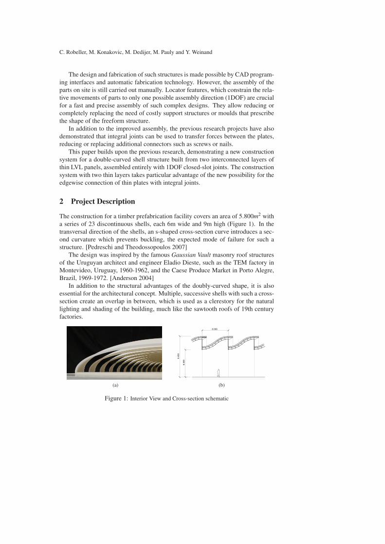
The construction for a timber prefabrication facility covers an area of 5.800m2 with
a series of 23 discontinuous shells, each 6m wide and 9m high (Figure 1). In the
transversal direction of the shells, an s-shaped cross-section curve introduces a sec-
ond curvature which prevents buckling, the expected mode of failure for such a
structure. [Pedreschi and Theodossopoulos 2007]
The design was inspired by the famous Gaussian Vault masonry roof structures
of the Uruguyan architect and engineer Eladio Dieste, such as the TEM factory in
Montevideo, Uruguay, 1960-1962, and the Caese Produce Market in Porto Alegre,
Brazil, 1969-1972. [Anderson 2004]
In addition to the structural advantages of the doubly-curved shape, it is also
essential for the architectural concept. Multiple, successive shells with such a cross-
section create an overlap in between, which is used as a clerestory for the natural
lighting and shading of the building, much like the sawtooth roofs of 19th century
factories.
(a)
9.450
6.300
6.000
(b)
Figure 1: Interior View and Cross-section schematic
A Double-layered Timber Plate Shell
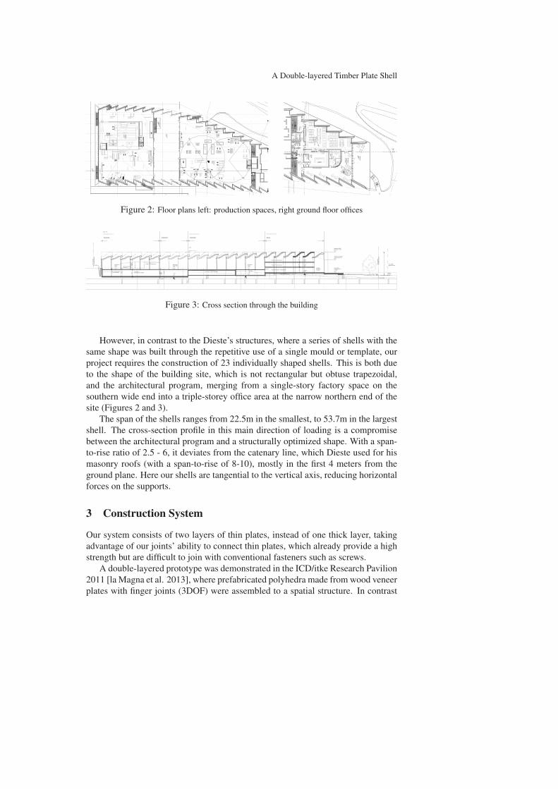
Figure 2: Floor plans left: production spaces, right ground floor offices
Figure 3: Cross section through the building
However, in contrast to the Dieste’s structures, where a series of shells with the
same shape was built through the repetitive use of a single mould or template, our
project requires the construction of 23 individually shaped shells. This is both due
to the shape of the building site, which is not rectangular but obtuse trapezoidal,
and the architectural program, merging from a single-story factory space on the
southern wide end into a triple-storey office area at the narrow northern end of the
site (Figures 2 and 3).
The span of the shells ranges from 22.5m in the smallest, to 53.7m in the largest
shell. The cross-section profile in this main direction of loading is a compromise
between the architectural program and a structurally optimized shape. With a span-
to-rise ratio of 2.5 - 6, it deviates from the catenary line, which Dieste used for his
masonry roofs (with a span-to-rise of 8-10), mostly in the first 4 meters from the
ground plane. Here our shells are tangential to the vertical axis, reducing horizontal
forces on the supports.
3 Construction System
Our system consists of two layers of thin plates, instead of one thick layer, taking
advantage of our joints’ ability to connect thin plates, which already provide a high
strength but are difficult to join with conventional fasteners such as screws.
A double-layered prototype was demonstrated in the ICD/itke Research Pavilion
2011 [la Magna et al. 2013], where prefabricated polyhedra made from wood veneer
plates with finger joints (3DOF) were assembled to a spatial structure. In contrast
C. Robeller, M. Konakovic, M. Dedijer, M. Pauly and Y. Weinand
to this project, our system uses 1DOF integral joints not only within segments /
modules (in the previously mentioned project, prefabricated modules where joined
with metal connectors), but between all of the plates, in order to take advantage of
the locator and connector features everywhere in the structure.
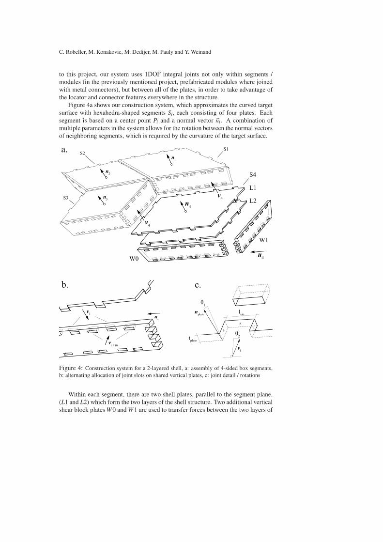
Figure 4a shows our construction system, which approximates the curved target
surface with hexahedra-shaped segments Si, each consisting of four plates. Each
segment is based on a center point Pi and a normal vector �ni. A combination of
multiple parameters in the system allows for the rotation between the normal vectors
of neighboring segments, which is required by the curvature of the target surface.
L1
S4
L2
W0
a.
b. c.
tplate
W1
v4
n4
n1
n2
n3
vi
vi
u4
ui
vi + m
ltabnplate
B
A
B
1
2
v4
S1S2
S3
Figure 4: Construction system for a 2-layered shell, a: assembly of 4-sided box segments,
b: alternating allocation of joint slots on shared vertical plates, c: joint detail / rotations
Within each segment, there are two shell plates, parallel to the segment plane,
(L1 and L2) which form the two layers of the shell structure. Two additional vertical
shear block plates W0 and W1 are used to transfer forces between the two layers of
A Double-layered Timber Plate Shell
the shell. There are no plates for the remaining two vertical faces of the hexahedron,
because these plates are shared with the neighboring segments.
Figure 4b shows how a vertical plate supports the connection of the main layers
of the shell: The intersection area of the three plates is divided into alternating
segments, creating slots which receive the tabs of the shell plates. This allows for
a direct contact between the shell plates for the transfer of compressive forces. In
between these slots and on the top and bottom face of all tabs, the vertical plate
holds the shell plates.
The assembly of the segments follows their numbering. Figure 4 shows the
assembly of Segment S4 in an m ∗ n matrix of segments. Within a segment, the
shell plates are inserted first, along the segment’s assembly vector �vi. They connect
simultaneously to the two shear block plates of the neighboring segments Si−1 and
Si−m. The slots in these neighboring shear plates are oriented along �vi, to receive
the tenons of the shell plates L1i and L2i.
3.1 Joints
Figure 4c shows a close-up view of the through-tenon joints that connect the shell
plates. We have chosen these so called closed-slot connectors, because they combine
the benefits of dovetail joints with additional features. Like the dovetails, the shape
of the through-tenon joint are kinematically classified as prismatic pins with slots,
constraining the Mobility of parts to one assembly motion path (M = 1) [Whitney
2004]. This shape fully integrates a unique position of the parts within the structure
and allows for a rapid and precise assembly.
While the 1DOF property is also provided by open-slot dovetail joints, through-
tenon joints provide additional features for the transfer of forces. The bending
strength of different types of multiple-tab-and-slot plate joints (MTSJ) has been
compared by [Roche et al. 2015a], demonstrating that joints with a closed slot, also
called through-tenon joints, combine the high shear strength of finger- and dovetail
joints (see [Roche et al. 2015b]) with a high bending strength.
Like dovetail joints, through-tenon joints connect plates in two planes. The av-
erage dihedral angle ϕmean = 6.5◦ between our shell plates is too small for the use
of such joints. We solve this problem with the connection through the vertical shear
plates in between shell plates. This connection requires only a small rotation θ1 of
the joint faces about the edge line (see Figure 4c, faces marked A).
However, the assembly of our system requires a second rotation of the tabs θ2,
about the normal vector of the plate, because we want to connect two non-parallel
edges simultaneously, along the same direction �vi.
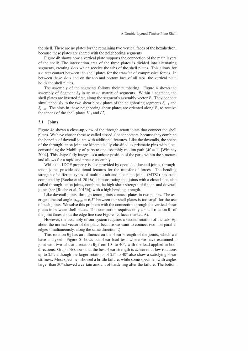
This rotation θ2 has an influence on the shear strength of the joints, which we
have analyzed. Figure 5 shows our shear load test, where we have examined a
joint with two tabs at a rotation θ2 from 10◦ to 40◦, with the load applied in both
directions. Graph 5b shows that the best shear strength is achieved at low rotations
up to 25◦, although the larger rotations of 25◦ to 40◦ also show a satisfying shear
stiffness. Most specimen showed a brittle failure, while some specimen with angles
larger than 30◦ showed a certain amount of hardening after the failure. The bottom
C. Robeller, M. Konakovic, M. Dedijer, M. Pauly and Y. Weinand
graph shows the load/displacement behaviour in the linear elastic range of 10-40%.
(a) Load Test Setup
0 1 2 3 4 5 60
20
40
60
80
100
120
140
160
180 10°15°20°25°30°35°40°
Force(kN)
Vertical displacement (mm)
0.0 0.1 0.2 0.3 0.4 0.5 0.6 0.70
5
10
15
20
25
30
35
40
45
50
Force(kN)
Vertical displacement (mm)
10°15°20°25°30°35°40°
(b) top: load/displacement curves for θ2 from 10◦ to
40◦, bottom: linear elastic range (10-40%)
Figure 5: Experimental analysis of the influence of the tab rotation θ2 on the shear stiffness
of the joints on 40mm cross-laminated LVL plates.
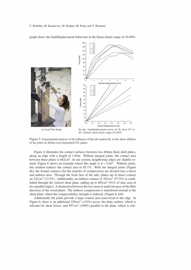
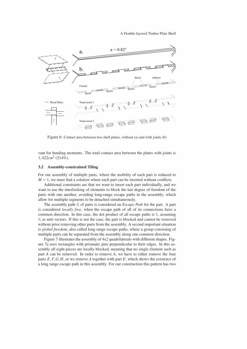
Figure 6 illustrates the contact surfaces between two 40mm thick shell plates,
along an edge with a length of 1.65m. Without integral joints, the contact area
between these plates is 662cm2. In our system, neighboring edges are slightly ro-
tated, Figure 6 shows an example where this angle is κ = 0.82◦. Without joints,
this rotation reduces the contact area to 85.1%. With our integral joints (Figure
6b), the frontal contacts (for the transfer of compression) are divided into a direct
and indirect area. Through the front face of the tabs, plates are in direct contact
on 222cm2 (33.5%). Additionally, an indirect contact of 383cm2 (57.5%) is estab-
lished through the vertical shear plate, adding up to 605cm2 (91% of max area of
two parallel edges). A distinction between the two areas is made because of the fiber
direction of the wood plates. The indirect compression is transferred normal to the
shear plate, where the compressibility strength is reduced. (Figure 6, left)
Additionally the joints provide a large contact area transversal to the edge. In
Figure 6, there is an additional 220cm2 (+33%) across the plate surface, which is
relevant for shear forces, and 597cm2 (+90%) parallel to the plate, which is rele-
A Double-layered Timber Plate Shell
indirectdirect
Frontal
Figure 6: Contact area between two shell plates, without (a) and with joints (b)
vant for bending moments. The total contact area between the plates with joints is
1,422cm2 (214%).
3.2 Assembly-constrained Tiling
For our assembly of multiple parts, where the mobility of each part is reduced to
M = 1, we must find a solution where each part can be inserted without conflicts.
Additional constraints are that we want to insert each part individually, and we
want to use the interlocking of elements to block the last degree of freedom of the
parts with one another, avoiding long-range escape paths in the assembly, which
allow for multiple segments to be detached simultaneously.
The assembly path �vi of parts is considered an Escape Path for the part. A part
is considered locally free, when the escape path of all of its connections have a
common direction. In this case, the dot product of all escape paths is 1, assuming
�vi as unit vectors. If this is not the case, the part is blocked and cannot be removed
without prior removing other parts from the assembly. A second important situation
is global freedom, also called long range escape paths, where a group consisting of
multiple parts can be separated from the assembly along one common direction.
Figure 7 illustrates the assembly of 4x2 quadrilaterals with different shapes. Fig-
ure 7a uses rectangles with prismatic pins perpendicular to their edges. In this as-
sembly all eight pieces are locally blocked, meaning that no single element such as
part A can be removed. In order to remove A, we have to either remove the four
parts E,F,G,H, or we remove A together with part E, which shows the existence of
a long range escape path in this assembly. For our construction this pattern has two
C. Robeller, M. Konakovic, M. Dedijer, M. Pauly and Y. Weinand
2 2
a. b. c. d.A B C D
E F G H
A B C D
E F
A B C D
EFG H
A B C D
E F G H H G
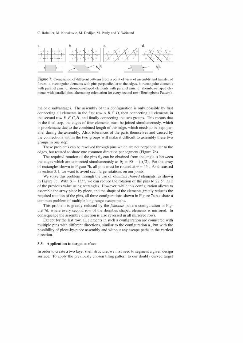
Figure 7: Comparison of different patterns from a point of view of assembly and transfer of
forces: a. rectangular elements with pins perpendicular to the edges, b. rectangular elements
with parallel pins, c. rhombus-shaped elements with parallel pins, d. rhombus-shaped ele-
ments with parallel pins, alternating orientation for every second row (Herringbone Pattern).
major disadvantages. The assembly of this configuration is only possible by first
connecting all elements in the first row A,B,C,D, then connecting all elements in
the second row E,F,G,H, and finally connecting the two groups. This means that
in the final step, the edges of four elements must be joined simultaneously, which
is problematic due to the combined length of this edge, which needs to be kept par-
allel during the assembly. Also, tolerances of the parts themselves and caused by
the connections within the two groups will make it difficult to assembly these two
groups in one step.
These problems can be resolved through pins which are not perpendicular to the
edges, but rotated to share one common direction per segment (Figure 7b).
The required rotation of the pins θ2 can be obtained from the angle α between
the edges which are connected simultaneously as θ2 = 90◦ − (α/2). For the array
of rectangles shown in Figure 7b, all pins must be rotated at θ = 45◦. As discussed
in section 3.1, we want to avoid such large rotations on our joints.
We solve this problem through the use of rhombus shaped elements, as shown
in Figure 7c. With α = 135◦, we can reduce the rotation of the pins to 22.5◦, half
of the previous value using rectangles. However, while this configuration allows to
assemble the array piece by piece, and the shape of the elements greatly reduces the
required rotation of the pins, all three configurations shown in Figure 7a,b,c share a
common problem of multiple long range escape paths.
This problem is greatly reduced by the fishbone pattern configuration in Fig-
ure 7d, where every second row of the rhombus shaped elements is mirrored. In
consequence the assembly direction is also reversed in all mirrored rows.
Except for the last row, all elements in such a configuration are connected with
multiple pins with different directions, similar to the configuration a., but with the
possibility of piece-by-piece assembly and without any escape paths in the vertical
direction.
3.3 Application to target surface
In order to create a two layer shell structure, we first need to segment a given design
surface. To apply the previously chosen tiling pattern to our doubly curved target
A Double-layered Timber Plate Shell
surface, we use a first algorithm to generate the basic pattern through the evaluation
of a point grid on a NURBS surface.
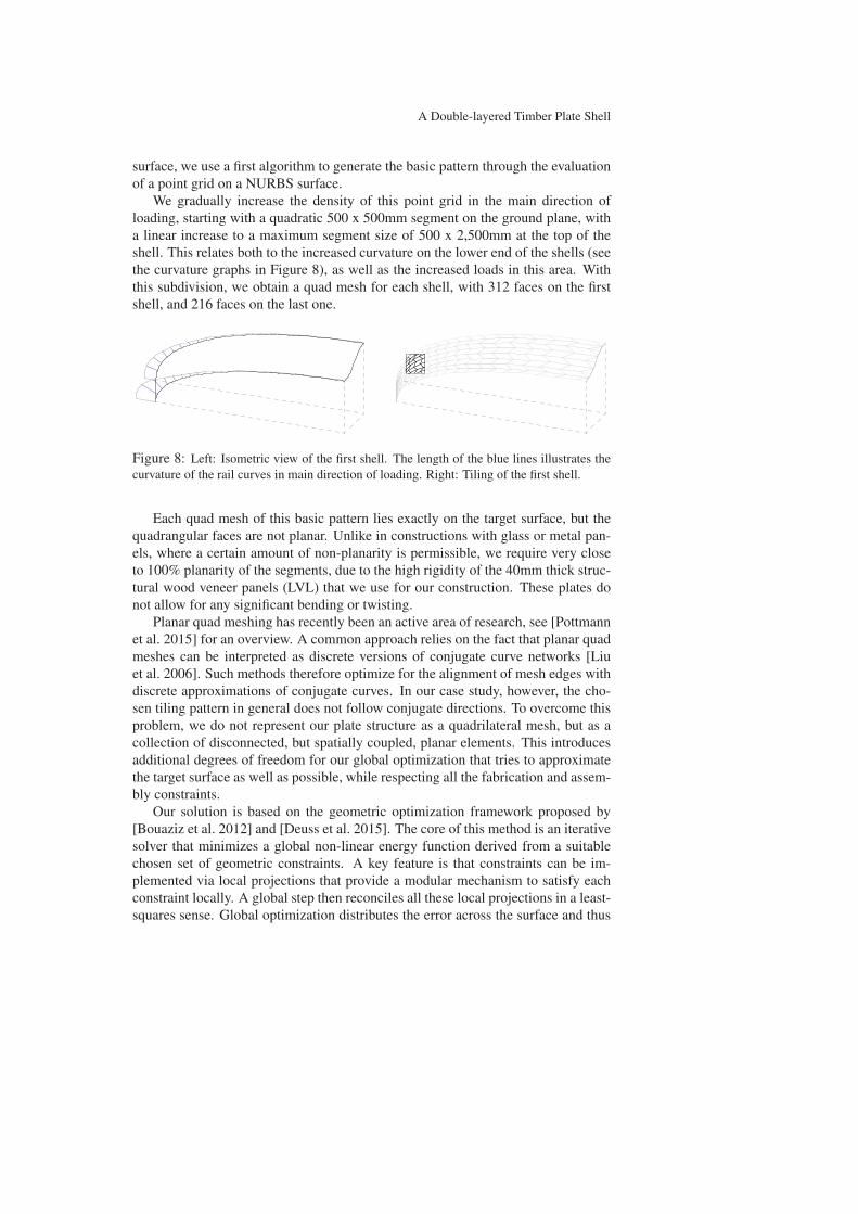
We gradually increase the density of this point grid in the main direction of
loading, starting with a quadratic 500 x 500mm segment on the ground plane, with
a linear increase to a maximum segment size of 500 x 2,500mm at the top of the
shell. This relates both to the increased curvature on the lower end of the shells (see
the curvature graphs in Figure 8), as well as the increased loads in this area. With
this subdivision, we obtain a quad mesh for each shell, with 312 faces on the first
shell, and 216 faces on the last one.
Figure 8: Left: Isometric view of the first shell. The length of the blue lines illustrates the
curvature of the rail curves in main direction of loading. Right: Tiling of the first shell.
Each quad mesh of this basic pattern lies exactly on the target surface, but the
quadrangular faces are not planar. Unlike in constructions with glass or metal pan-
els, where a certain amount of non-planarity is permissible, we require very close
to 100% planarity of the segments, due to the high rigidity of the 40mm thick struc-
tural wood veneer panels (LVL) that we use for our construction. These plates do
not allow for any significant bending or twisting.
Planar quad meshing has recently been an active area of research, see [Pottmann
et al. 2015] for an overview. A common approach relies on the fact that planar quad
meshes can be interpreted as discrete versions of conjugate curve networks [Liu
et al. 2006]. Such methods therefore optimize for the alignment of mesh edges with
discrete approximations of conjugate curves. In our case study, however, the cho-
sen tiling pattern in general does not follow conjugate directions. To overcome this
problem, we do not represent our plate structure as a quadrilateral mesh, but as a
collection of disconnected, but spatially coupled, planar elements. This introduces
additional degrees of freedom for our global optimization that tries to approximate
the target surface as well as possible, while respecting all the fabrication and assem-
bly constraints.
Our solution is based on the geometric optimization framework proposed by
[Bouaziz et al. 2012] and [Deuss et al. 2015]. The core of this method is an iterative
solver that minimizes a global non-linear energy function derived from a suitable
chosen set of geometric constraints. A key feature is that constraints can be im-
plemented via local projections that provide a modular mechanism to satisfy each
constraint locally. A global step then reconciles all these local projections in a least-
squares sense. Global optimization distributes the error across the surface and thus
C. Robeller, M. Konakovic, M. Dedijer, M. Pauly and Y. Weinand
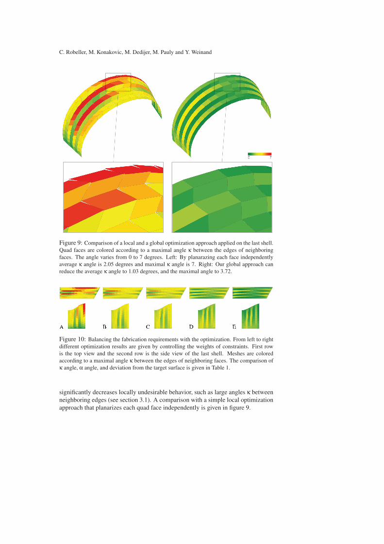
Figure 9: Comparison of a local and a global optimization approach applied on the last shell.
Quad faces are colored according to a maximal angle κ between the edges of neighboring
faces. The angle varies from 0 to 7 degrees. Left: By planarazing each face independently
average κ angle is 2.05 degrees and maximal κ angle is 7. Right: Our global approach can
reduce the average κ angle to 1.03 degrees, and the maximal angle to 3.72.
Figure 10: Balancing the fabrication requirements with the optimization. From left to right
different optimization results are given by controlling the weights of constraints. First row
is the top view and the second row is the side view of the last shell. Meshes are colored
according to a maximal angle κ between the edges of neighboring faces. The comparison of
κ angle, α angle, and deviation from the target surface is given in Table 1.
significantly decreases locally undesirable behavior, such as large angles κ between
neighboring edges (see section 3.1). A comparison with a simple local optimization
approach that planarizes each quad face independently is given in figure 9.

A Double-layered Timber Plate Shell
Table 1: Optimization tradeoffs
Optimization A B C D E
Average kappa angle 2.05◦ 1.9◦ 1.7◦ 1.3◦ 1.03◦Maximal kappa angle 6.93◦ 5.5◦ 5.1◦ 4.4◦ 3.72◦Average alpha angle 121.4◦ 118.7◦ 116.9◦ 112.4◦ 110.6◦Minimal alpha angle 106.5◦ 105.4◦ 102.1◦ 100.1◦ 100.3◦Average surface deviation 13.5mm 30.9mm 38.6mm 42.3mm 46.2mm
Below we give a summary of the different constraints we use in our optimiza-
tion. These constraints are equipped with weights that allow balancing the trade-
offs inherent in our over-constrained optimization. Please refer to [Deuss et al.
2015] for a derivation of the constraints and a more detailed description of their
implementation. An open-source implementation of the solver can be found at
http://shapeop.org/.
To optimize our plate assembly we use the following constraints:
• Planarity of the four vertices of each quadrilateral ensures fabricability. We
use a high weight to respect the very high stiffness of the LVL plates.
• Closeness links the quads to the target surface. We set high weights for ver-
tices on the boundary to match the site requirements. For interior vertices we
use lower weights so that elements can adapt in size and shape, if necessary
to satisfy fabrication and assembly objectives.
• Angle bounds the angles of each quad face to preserve the initial rhomboid
shape and avoid rectangular faces.
• Parallelogram is used with a low weight for aesthetic reasons on the non-
boundary elements.
• Divergence is a new constraint that we introduce specifically to handle our
disconnected plate arrangement. This constraint couples adjacent plates by
minimizing the distance between neighboring vertices. The projection oper-
ator for this constraint is simply given as the mean position of two vertices,
applied on each pair of adjacent vertices as defined by the topology of the grid
layout.
The global optimization in figure 10 and table 1 reduces the average kappa angles
κmean by up to 50%, compared to the local optimization. This is possible through
a trade-off between multiple parameters. We allow for a controlled deviation from
the base surface and for the alpha angles. Option C shows a balanced compromise,
where κmean is reduced by 17%. At the same time αmean is well preserved with a loss
of only 2.2% compared to the local optimization (Option A), avoiding any negative
effects on the mechanical strength of the joints.
C. Robeller, M. Konakovic, M. Dedijer, M. Pauly and Y. Weinand
88
11
89
166
90
91
168
169
170
171
93
92
e2
e2
e2
e2
e2
e2
e2
e2
e2
e2
e2
e2
e1
e1
e1
e1
e1
e1
e1
e3
e3
e3
e3
e3
e3
e3
e3
e3
e3
e3
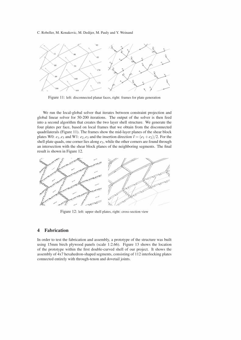
Figure 11: left: disconnected planar faces, right: frames for plate generation
We run the local-global solver that iterates between constraint projection and
global linear solver for 50-200 iterations. The output of the solver is then feed
into a second algorithm that creates the two layer shell structure. We generate the
four plates per face, based on local frames that we obtain from the disconnected
quadrilaterals (Figure 11). The frames show the mid-layer planes of the shear block
plates W0: e1,e3 and W1: e2,e3 and the insertion direction�v = (e1 +e2)/2. For the
shell plate quads, one corner lies along e3, while the other corners are found through
an intersection with the shear block planes of the neighboring segments. The final
result is shown in Figure 12.
Figure 12: left: upper shell plates, right: cross-section view
4 Fabrication
In order to test the fabrication and assembly, a prototype of the structure was built
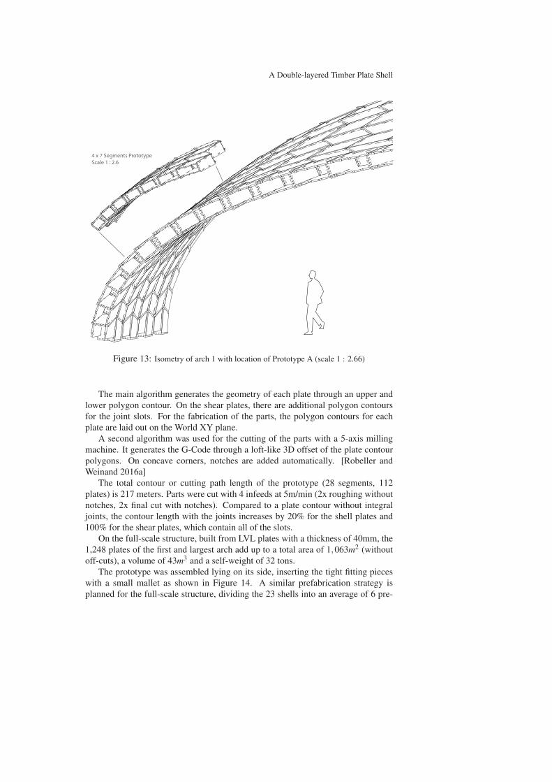
using 15mm birch plywood panels (scale 1:2.66). Figure 13 shows the location
of the prototype within the first double-curved shell of our project. It shows the
assembly of 4x7 hexahedron-shaped segments, consisting of 112 interlocking plates
connected entirely with through-tenon and dovetail joints.
A Double-layered Timber Plate Shell
4 x 7 Segments PrototypeScale 1 : 2.6
Figure 13: Isometry of arch 1 with location of Prototype A (scale 1 : 2.66)
The main algorithm generates the geometry of each plate through an upper and
lower polygon contour. On the shear plates, there are additional polygon contours
for the joint slots. For the fabrication of the parts, the polygon contours for each
plate are laid out on the World XY plane.
A second algorithm was used for the cutting of the parts with a 5-axis milling
machine. It generates the G-Code through a loft-like 3D offset of the plate contour
polygons. On concave corners, notches are added automatically. [Robeller and
Weinand 2016a]
The total contour or cutting path length of the prototype (28 segments, 112
plates) is 217 meters. Parts were cut with 4 infeeds at 5m/min (2x roughing without
notches, 2x final cut with notches). Compared to a plate contour without integral
joints, the contour length with the joints increases by 20% for the shell plates and
100% for the shear plates, which contain all of the slots.
On the full-scale structure, built from LVL plates with a thickness of 40mm, the
1,248 plates of the first and largest arch add up to a total area of 1,063m2 (without
off-cuts), a volume of 43m3 and a self-weight of 32 tons.
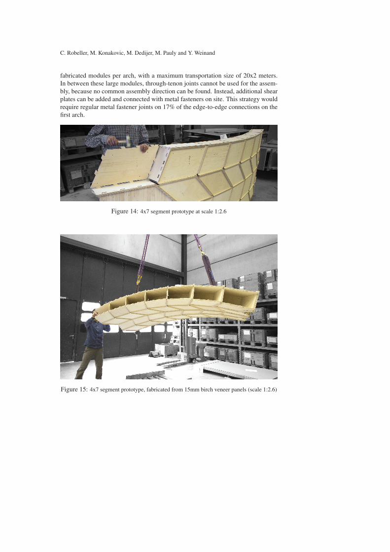
The prototype was assembled lying on its side, inserting the tight fitting pieces
with a small mallet as shown in Figure 14. A similar prefabrication strategy is
planned for the full-scale structure, dividing the 23 shells into an average of 6 pre-
C. Robeller, M. Konakovic, M. Dedijer, M. Pauly and Y. Weinand
fabricated modules per arch, with a maximum transportation size of 20x2 meters.
In between these large modules, through-tenon joints cannot be used for the assem-
bly, because no common assembly direction can be found. Instead, additional shear
plates can be added and connected with metal fasteners on site. This strategy would
require regular metal fastener joints on 17% of the edge-to-edge connections on the
first arch.
Figure 14: 4x7 segment prototype at scale 1:2.6
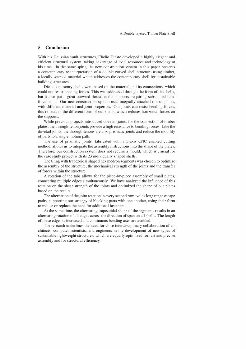
Figure 15: 4x7 segment prototype, fabricated from 15mm birch veneer panels (scale 1:2.6)
A Double-layered Timber Plate Shell
5 Conclusion
With his Gaussian vault structures, Eladio Dieste developed a highly elegant and
efficient structural system, taking advantage of local resources and technology at
his time. In the same spirit, the new construction system in this paper presents
a contemporary re-interpretation of a double-curved shell structure using timber,
a locally sourced material which addresses the contemporary shell for sustainable
building structures.
Dieste’s masonry shells were based on the material and its connections, which
could not resist bending forces. This was addressed through the form of the shells,
but it also put a great outward thrust on the supports, requiring substantial rein-
forcements. Our new construction system uses integrally attached timber plates,
with different material and joint properties. Our joints can resist bending forces,
this reflects in the different form of our shells, which reduces horizontal forces on
the supports.
While previous projects introduced dovetail joints for the connection of timber
plates, the through-tenon joints provide a high resistance to bending forces. Like the
dovetail joints, the through-tenons are also prismatic joints and reduce the mobility
of parts to a single motion path.
The use of prismatic joints, fabricated with a 5-axis CNC enabled cutting
method, allows us to integrate the assembly instructions into the shape of the plates.
Therefore, our construction system does not require a mould, which is crucial for
the case study project with its 23 individually shaped shells.
The tiling with trapezoidal shaped hexahedron segments was chosen to optimize
the assembly of the structure, the mechanical strength of the joints and the transfer
of forces within the structure.
A rotation of the tabs allows for the piece-by-piece assembly of small plates,
connecting multiple edges simultaneously. We have analyzed the influence of this
rotation on the shear strength of the joints and optimized the shape of our plates
based on the results.
The alternation of the joint rotation in every second row avoids long range escape
paths, supporting our strategy of blocking parts with one another, using their form
to reduce or replace the need for additional fasteners.
At the same time, the alternating trapezoidal shape of the segments results in an
alternating rotation of all edges across the direction of span on all shells. The length
of these edges is increased and continuous bending axes are avoided.
The research underlines the need for close interdisciplinary collaboration of ar-
chitects, computer scientists, and engineers in the development of new types of
sustainable lightweight structures, which are equally optimized for fast and precise
assembly and for structural efficiency.
C. Robeller, M. Konakovic, M. Dedijer, M. Pauly and Y. Weinand
Acknowledgments
This research was supported by the NCCR Digital Fabrication, funded by the Swiss
National Science Foundation. (NCCR Digital Fabrication Agreement #51NF40-
141853))
References
ANDERSON, S. 2004. Eladio Dieste: Innovation in Structural Art. Princeton
Architectural Press.
BOUAZIZ, S., DEUSS, M., SCHWARTZBURG, Y., WEISE, T., AND PAULY, M.
2012. Shape-up: Shaping discrete geometry with projections. Comput. Graph.Forum 31, 5 (Aug.).
DEUSS, M., DELEURAN, A. H., BOUAZIZ, S., DENG, B., PIKER, D., AND
PAULY, M. 2015. Modelling Behaviour: Design Modelling Symposium 2015.
Springer International Publishing, Cham, ch. ShapeOp—A Robust and Extensi-
ble Geometric Modelling Paradigm, 505–515.
KRIEG, O. D., SCHWINN, T., MENGES, A., LI, J.-M., KNIPPERS, J., SCHMITT,
A., AND SCHWIEGER, V. 2015. Advances in Architectural Geometry 2014.
Springer International Publishing, Cham, ch. Biomimetic Lightweight Timber
Plate Shells: Computational Integration of Robotic Fabrication, Architectural
Geometry and Structural Design, 109–125.
LA MAGNA ET AL., R. 2013. From nature to fabrication: Biomimetic design
principles for the production of complex spatial structures. International Journalof Spatial Structures 28, 01, 27–40. Doi: 10.1260/0266-3511.28.1.27 (ISSN
0266-3511).
LI, J.-M., AND KNIPPERS, J. 2015. Segmental timber plate shell for the lan-
desgartenschau exhibition hall in schwabisch gmund—the application of finger
joints in plate structures. International Journal of Space Structures 30, 2, 123–
140.
LIU, Y., POTTMANN, H., WALLNER, J., YANG, Y.-L., AND WANG, W. 2006.
Geometric modeling with conical meshes and developable surfaces. ACM Trans.Graph. 25, 3 (July), 681–689.
PEDRESCHI, R., AND THEODOSSOPOULOS, D. 2007. The double-curvature ma-
sonry vaults of eladio dieste. Proceedings of the ICE - Structures and Buildings160, 1 (2), 3–11.
POTTMANN, H., EIGENSATZ, M., VAXMAN, A., AND WALLNER, J. 2015. Ar-
chitectural geometry. Computers and Graphics 47, 145–164.
ROBELLER, C., AND WEINAND, Y. 2015. Interlocking folded plate – integral me-
chanical attachment for structural wood panels. International Journal of SpaceStructures 30, 2, 111–122.
A Double-layered Timber Plate Shell
ROBELLER, C., AND WEINAND, Y. 2016. A 3d cutting method for integral 1dof
multiple-tab-and-slot joints for timber plates, using 5-axis cnc cutting technol-
ogy. In Proceedings of the World Conference on Timber Engineering WCTE2016.
ROBELLER, C., AND WEINAND, Y. 2016. Robotic Fabrication in Architecture,Art and Design 2016. Springer International Publishing, Cham, ch. Fabrication-
Aware Design of Timber Folded Plate Shells with Double Through Tenon Joints,
166–177.
ROCHE, S., MATTONI, G., AND WEINAND, Y. 2015. Rotational stiffness at ridges
of timber folded-plate structures. International Journal of Space Structures 30,
2, 153–168.
ROCHE, S., ROBELLER, C., HUMBERT, L., AND WEINAND, Y. 2015. On the
semi-rigidity of dovetail joint for the joinery of lvl panels. European Journal ofWood and Wood Products 73, 5, 667–675.
WHITNEY, D. 2004. Mechanical Assemblies: Their Design, Manufacture, and Rolein Product Development. No. Bd. 1 in Mechanical Assemblies: Their Design,
Manufacture, and Role in Product Development. Oxford University Press.
Authors’ address:
Christopher Robeller ([email protected]): EPFL Laboratory for Timber
Construction IBOIS / Station 18 — CH 1015 Lausanne.
Mina Konakovic ([email protected]): EPFL Computer Graphics Laboratory
LGG / Station 14 — CH 1015 Lausanne.
Mira Dedijer ([email protected]): EPFL Laboratory for Timber Construction
IBOIS / Station 18 — CH 1015 Lausanne.
Yves Weinand ([email protected]): EPFL Laboratory for Timber Construction
IBOIS / Station 18 — CH 1015 Lausanne.
Mark Pauly ([email protected]): EPFL Computer Graphics Laboratory LGG /
Station 14 — CH 1015 Lausanne.