Embed Size (px)
Citation preview
10th Canadian Masonry Symposium, Banff, Alberta, June 8 – 12, 2005
DESIGN ASSISTED BY TESTING OF SEMI-PREFABRICATED REINFORCED BRICK MASONRY VAULTS
F.da Porto, F. Casarin, E. Garbin, M. Grendene, C. Modena, M.R. Valluzzi
Dept. of Structural and Transportation Eng., University of Padova, Via Marzolo 9, 35131 Padova, Italy [email protected]
ABSTRACT In the framework of the European contract CRAFT-1999-70420 ‘ISO-BRICK’, several European institutions and private companies developed a semi-prefabricated solution for short and medium span shell roofs, inspired by the innovative curved masonry shells for roofs and walls designed by the well-known Uruguayan architect and engineer Eladio Dieste. The main aim of the research was that of finding an industrialized solution for the construction of those elements and to prove their structural reliability. As part of the research, two prototype buildings were built in Italy. To get all the necessary data for design, as assumed in prEN 1990 (1990), a series of tests to obtain specific material properties and to reduce uncertainties in resistance models were carried out at the University of Padua. A full size model of the curved shell was built and tested in order to evaluate the ultimate resistance. Dynamic tests were carried out at different levels of damage during the static loading tests. Test on small specimens were carried out to evaluate the feasibility of construction and properties related to the durability of the construction. On the basis of the gained knowledge, the two buildings were designed and built, and subsequently control tests to check the behaviour of the actual structures were carried out. KEYWORDS: semi-prefabrication; reinforced masonry shells; design by testing. INTRODUCTION Eladio Dieste (1917–2000), was a well-known Uruguayan architect and engineer who designed a significant number of innovative curved reinforced brick masonry shells for roofs and walls, that were built mainly in South America since 1950 (see, for example, Figure 1). These shells constituted the development and the junction of two different types of structure: the light brick vaults typical of the Catalan building tradition, successfully used in the USA and in Spain between the end of the XIX Century and the beginning of the XX Century, and the light vaulted concrete structures developed during the first half of the past century [2]. As in the latter, Dieste’s shells made use of reinforcement in order to push the spans to larger dimensions, reaching even 50 meters. The use of clay units at the intrados, arranged in stack-bonded pattern, allowed a further lightening of the structure, providing at the same time the location for the placement of steel reinforcement. The reinforced joints and the thin topping were made of mortar.
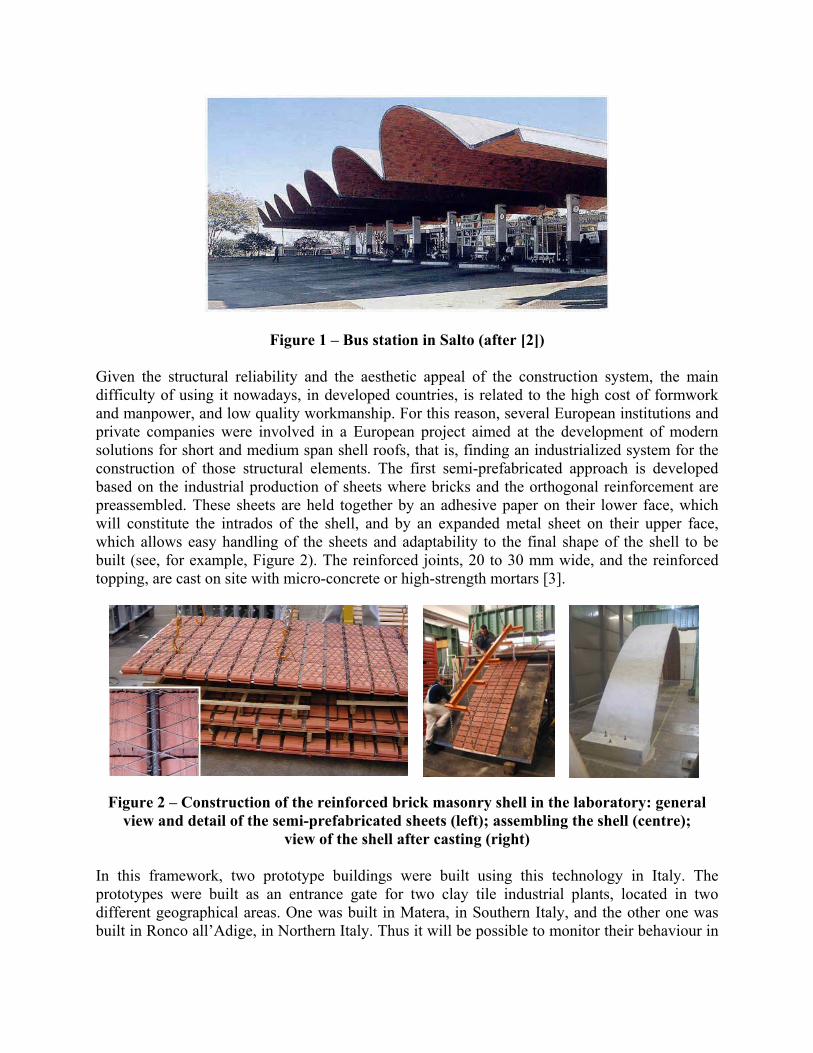
Figure 1 – Bus station in Salto (after [2]) Given the structural reliability and the aesthetic appeal of the construction system, the main difficulty of using it nowadays, in developed countries, is related to the high cost of formwork and manpower, and low quality workmanship. For this reason, several European institutions and private companies were involved in a European project aimed at the development of modern solutions for short and medium span shell roofs, that is, finding an industrialized system for the construction of those structural elements. The first semi-prefabricated approach is developed based on the industrial production of sheets where bricks and the orthogonal reinforcement are preassembled. These sheets are held together by an adhesive paper on their lower face, which will constitute the intrados of the shell, and by an expanded metal sheet on their upper face, which allows easy handling of the sheets and adaptability to the final shape of the shell to be built (see, for example, Figure 2). The reinforced joints, 20 to 30 mm wide, and the reinforced topping, are cast on site with micro-concrete or high-strength mortars [3].
Figure 2 – Construction of the reinforced brick masonry shell in the laboratory: general view and detail of the semi-prefabricated sheets (left); assembling the shell (centre);
view of the shell after casting (right) In this framework, two prototype buildings were built using this technology in Italy. The prototypes were built as an entrance gate for two clay tile industrial plants, located in two different geographical areas. One was built in Matera, in Southern Italy, and the other one was built in Ronco all’Adige, in Northern Italy. Thus it will be possible to monitor their behaviour in
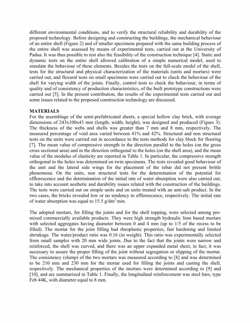
different environmental conditions, and to verify the structural reliability and durability of the proposed technology. Before designing and constructing the buildings, the mechanical behaviour of an entire shell (Figure 2) and of smaller specimens prepared with the same building process of the entire shell was assessed by means of experimental tests, carried out at the University of Padua. It was thus possible to test also the feasibility of the construction technique [4]. Static and dynamic tests on the entire shell allowed calibration of a simple numerical model, used to simulate the behaviour of these elements. Besides the tests on the full-scale model of the shell, tests for the structural and physical characterization of the materials (units and mortars) were carried out, and flexural tests on small specimens were carried out to check the behaviour of the shell for varying width of the joints. Finally, control tests to check the behaviour, in terms of quality and of consistency of production characteristics, of the built prototype constructions were carried out [5]. In the present contribution, the results of the experimental tests carried out and some issues related to the proposed construction technology are discussed. MATERIALS For the assemblage of the semi-prefabricated sheets, a special hollow clay brick, with average dimensions of 243x100x43 mm (length, width, height), was designed and produced (Figure 3). The thickness of the webs and shells was greater than 7 mm and 8 mm, respectively. The measured percentage of void area varied between 41% and 42%. Structural and non structural tests on the units were carried out in accordance to the tests methods for clay block for flooring [7]. The mean value of compressive strength in the direction parallel to the holes (on the gross cross sectional area) and in the direction orthogonal to the holes (on the shell area), and the mean value of the modulus of elasticity are reported in Table 1. In particular, the compressive strength orthogonal to the holes was determined on twin specimens. The tests revealed good behaviour of the unit and the lateral side wings for the placement of the rebar did not present brittle phenomena. On the units, non structural tests for the determination of the potential for efflorescence and the determination of the initial rate of water absorption were also carried out, to take into account aesthetic and durability issues related with the construction of the buildings. The tests were carried out on simple units and on units treated with an anti-salt product. In the two cases, the bricks revealed low or no tendency to efflorescence, respectively. The initial rate of water absorption was equal to 15.5 g/dm2 min. The adopted mortars, for filling the joints and for the shell topping, were selected among pre-mixed commercially available products. They were high strength hydraulic lime based mortars with selected aggregates having diameter between 0 and 4 mm (up to 1/5 of the recess to be filled). The mortar for the joint filling had rheoplastic properties, fast hardening and limited shrinkage. The water/product ratio was 0.16 (in weight). This ratio was experimentally selected from small samples with 20 mm wide joints. Due to the fact that the joints were narrow and reinforced, the shell was curved, and there was an upper expanded metal sheet, in fact, it was necessary to assure the proper filling of the joint without segregation or slipping of the mortar. The consistency (slump) of the two mortars was measured according to [8] and was determined to be 210 mm and 230 mm for the mortar used for filling the joints and casting the shell, respectively. The mechanical properties of the mortars were determined according to [9] and [10], and are summarized in Table 1. Finally, the longitudinal reinforcement was steel bars, type Feb 44K, with diameter equal to 8 mm.
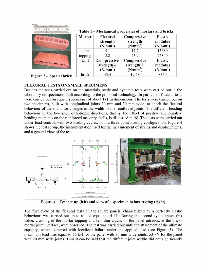
Table 1 – Mechanical properties of mortars and bricks
Figure 3 – Special brick
Mortar Flexural strength (N/mm2)
Compressive strength (N/mm2)
Elastic modulus (N/mm2)
joint 5.1 17.7 15680 topping 5.2 23.9 25840
Unit Compressive strength // (N/mm2)
Compressive strength ┴ (N/mm2)
Elastic modulus (N/mm2)
brick 43.4 19.28 8350 FLEXURAL TESTS ON SMALL SPECIMENS Besides the tests carried out on the materials, static and dynamic tests were carried out in the laboratory on specimens built according to the proposed technology. In particular, flexural tests were carried out on square specimens, of about 1x1 m dimensions. The tests were carried out on two specimens, built with longitudinal joints 20 mm and 30 mm wide, to check the flexural behaviour of the shells for changes in the width of the reinforced joints. The different bending behaviour in the two shell orthotropic directions, that is, the effect of positive and negative bending moments on the reinforced masonry shells, is discussed in [6]. The tests were carried out under load control, with two loading cycles, with a three point loading configuration. Figure 4 shows the test set-up, the instrumentation used for the measurement of strains and displacements, and a general view of the test.
Figure 4 – Test set-up (left) and view of a specimen before testing (right) The first cycle of the flexural tests on the square panels, characterized by a perfectly elastic behaviour, was carried out up to a load equal to 14 kN. During the second cycle, above this value, crushing of the mortar topping and few thin cracks on the panel intrados, at the brick-mortar joint interface, were observed. The test was carried out until the attainment of the ultimate capacity, which occurred with localized failure under the applied load (see Figure 5). The maximum load was equal to 55 kN for the panel with 30 mm wide joints, 53 kN for the panel with 20 mm wide joints. Thus it can be said that the different joint widths did not significantly
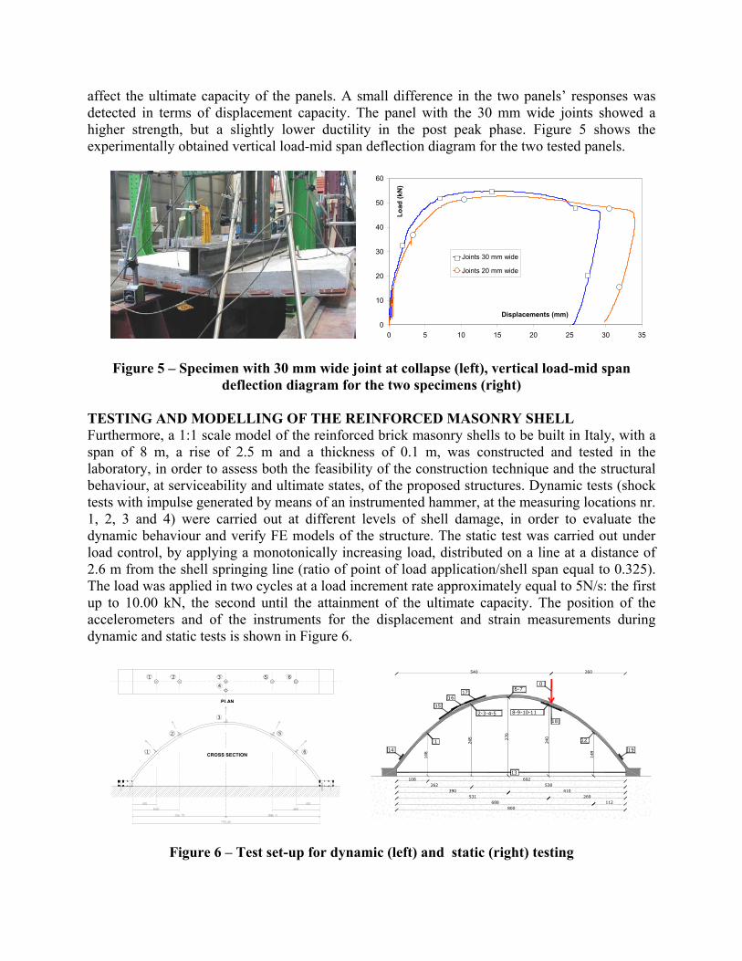
affect the ultimate capacity of the panels. A small difference in the two panels’ responses was detected in terms of displacement capacity. The panel with the 30 mm wide joints showed a higher strength, but a slightly lower ductility in the post peak phase. Figure 5 shows the experimentally obtained vertical load-mid span deflection diagram for the two tested panels.
0
10
20
30
40
50
60
0 5 10 15 20 25 30 35
Displacements (mm)
Load
(kN
)
Joints 30 mm wide
Joints 20 mm wide
Figure 5 – Specimen with 30 mm wide joint at collapse (left), vertical load-mid span deflection diagram for the two specimens (right)
TESTING AND MODELLING OF THE REINFORCED MASONRY SHELL Furthermore, a 1:1 scale model of the reinforced brick masonry shells to be built in Italy, with a span of 8 m, a rise of 2.5 m and a thickness of 0.1 m, was constructed and tested in the laboratory, in order to assess both the feasibility of the construction technique and the structural behaviour, at serviceability and ultimate states, of the proposed structures. Dynamic tests (shock tests with impulse generated by means of an instrumented hammer, at the measuring locations nr. 1, 2, 3 and 4) were carried out at different levels of shell damage, in order to evaluate the dynamic behaviour and verify FE models of the structure. The static test was carried out under load control, by applying a monotonically increasing load, distributed on a line at a distance of 2.6 m from the shell springing line (ratio of point of load application/shell span equal to 0.325). The load was applied in two cycles at a load increment rate approximately equal to 5N/s: the first up to 10.00 kN, the second until the attainment of the ultimate capacity. The position of the accelerometers and of the instruments for the displacement and strain measurements during dynamic and static tests is shown in Figure 6.
108262
390531
688800
1
148
2-3-4-5 8-9-10-11
6-7
12
13
14 19
15
1716
18
245 27
0
240
149
0
692538
410269
112
260540
Figure 6 – Test set-up for dynamic (left) and static (right) testing
1 2 3
4
5 6
1
2
3
6
5
3 393B12 sn 2793
4 393B12 sn 2794
5 393B12 sn 2792
6 393B12 sn 5875
CROSS SECTION
PLAN
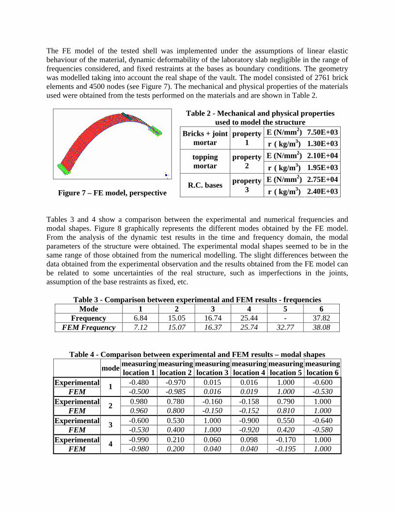
The FE model of the tested shell was implemented under the assumptions of linear elastic behaviour of the material, dynamic deformability of the laboratory slab negligible in the range of frequencies considered, and fixed restraints at the bases as boundary conditions. The geometry was modelled taking into account the real shape of the vault. The model consisted of 2761 brick elements and 4500 nodes (see Figure 7). The mechanical and physical properties of the materials used were obtained from the tests performed on the materials and are shown in Table 2.
Figure 7 – FE model, perspective
Table 2 - Mechanical and physical properties used to model the structure
E (N/mm2) 7.50E+03 Bricks + joint mortar
property 1 ρ ( kg/m3) 1.30E+03
E (N/mm2) 2.10E+04 topping mortar
property 2 ρ ( kg/m3) 1.95E+03
E (N/mm2) 2.75E+04 R.C. bases property
3 ρ ( kg/m3) 2.40E+03
Tables 3 and 4 show a comparison between the experimental and numerical frequencies and modal shapes. Figure 8 graphically represents the different modes obtained by the FE model. From the analysis of the dynamic test results in the time and frequency domain, the modal parameters of the structure were obtained. The experimental modal shapes seemed to be in the same range of those obtained from the numerical modelling. The slight differences between the data obtained from the experimental observation and the results obtained from the FE model can be related to some uncertainties of the real structure, such as imperfections in the joints, assumption of the base restraints as fixed, etc.
Table 3 - Comparison between experimental and FEM results - frequencies Mode 1 2 3 4 5 6
Frequency 6.84 15.05 16.74 25.44 - 37.82 FEM Frequency 7.12 15.07 16.37 25.74 32.77 38.08
Table 4 - Comparison between experimental and FEM results – modal shapes mode measuring
location 1 measuring location 2
measuring location 3
measuring location 4
measuring location 5
measuring location 6
Experimental -0.480 -0.970 0.015 0.016 1.000 -0.600 FEM
1 -0.500 -0.985 0.016 0.019 1.000 -0.530
Experimental 0.980 0.780 -0.160 -0.158 0.790 1.000 FEM
2 0.960 0.800 -0.150 -0.152 0.810 1.000
Experimental -0.600 0.530 1.000 -0.900 0.550 -0.640 FEM
3 -0.530 0.400 1.000 -0.920 0.420 -0.580
Experimental -0.990 0.210 0.060 0.098 -0.170 1.000 FEM
4 -0.980 0.200 0.040 0.040 -0.195 1.000
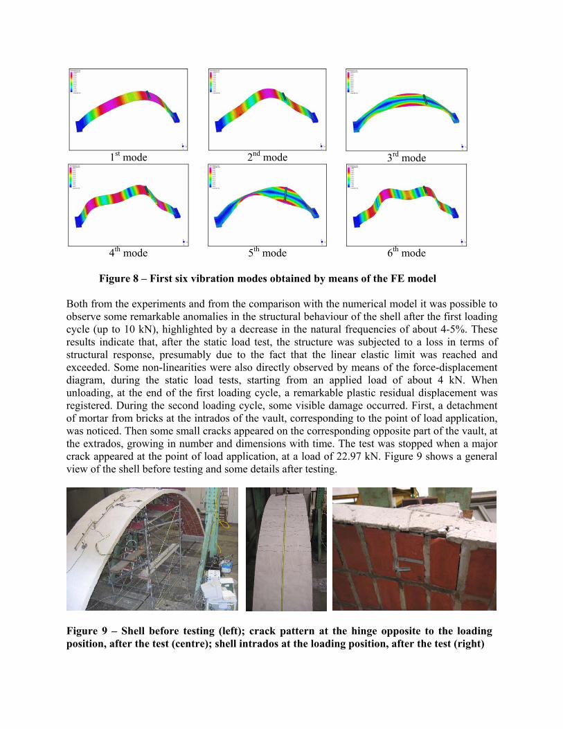
Both from the experiments and from the comparison with the numerical model it was possible to observe some remarkable anomalies in the structural behaviour of the shell after the first loading cycle (up to 10 kN), highlighted by a decrease in the natural frequencies of about 4-5%. These results indicate that, after the static load test, the structure was subjected to a loss in terms of structural response, presumably due to the fact that the linear elastic limit was reached and exceeded. Some non-linearities were also directly observed by means of the force-displacement diagram, during the static load tests, starting from an applied load of about 4 kN. When unloading, at the end of the first loading cycle, a remarkable plastic residual displacement was registered. During the second loading cycle, some visible damage occurred. First, a detachment of mortar from bricks at the intrados of the vault, corresponding to the point of load application, was noticed. Then some small cracks appeared on the corresponding opposite part of the vault, at the extrados, growing in number and dimensions with time. The test was stopped when a major crack appeared at the point of load application, at a load of 22.97 kN. Figure 9 shows a general view of the shell before testing and some details after testing.
Figure 9 – Shell before testing (left); crack pattern at the hinge opposite to the loading position, after the test (centre); shell intrados at the loading position, after the test (right)
1st mode
2nd mode
3rd mode
4th mode
5th mode
6th mode
Figure 8 – First six vibration modes obtained by means of the FE model
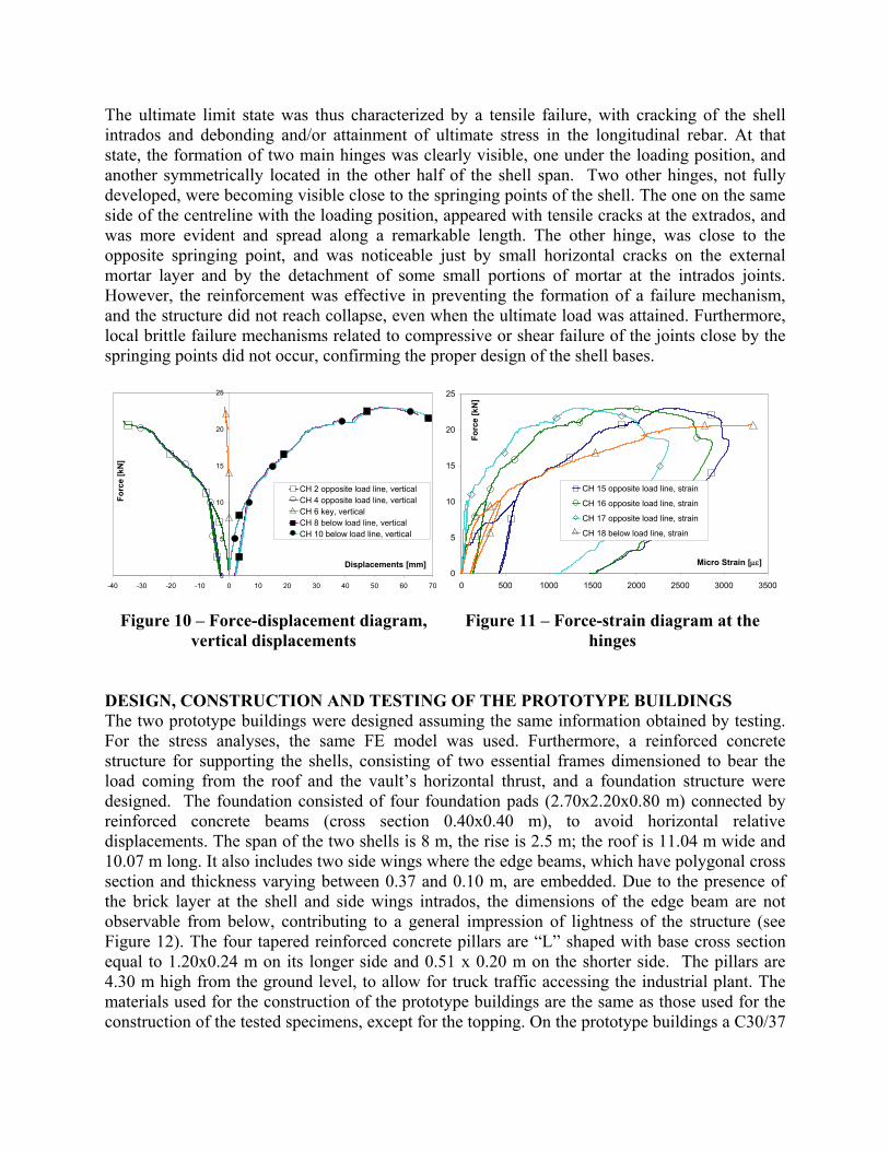
The ultimate limit state was thus characterized by a tensile failure, with cracking of the shell intrados and debonding and/or attainment of ultimate stress in the longitudinal rebar. At that state, the formation of two main hinges was clearly visible, one under the loading position, and another symmetrically located in the other half of the shell span. Two other hinges, not fully developed, were becoming visible close to the springing points of the shell. The one on the same side of the centreline with the loading position, appeared with tensile cracks at the extrados, and was more evident and spread along a remarkable length. The other hinge, was close to the opposite springing point, and was noticeable just by small horizontal cracks on the external mortar layer and by the detachment of some small portions of mortar at the intrados joints. However, the reinforcement was effective in preventing the formation of a failure mechanism, and the structure did not reach collapse, even when the ultimate load was attained. Furthermore, local brittle failure mechanisms related to compressive or shear failure of the joints close by the springing points did not occur, confirming the proper design of the shell bases.
0
5
10
15
20
25
-40 -30 -20 -10 0 10 20 30 40 50 60 70
Displacements [mm]
Forc
e [k
N]
CH 2 opposite load line, verticalCH 4 opposite load line, verticalCH 6 key, verticalCH 8 below load line, verticalCH 10 below load line, vertical
0
5
10
15
20
25
0 500 1000 1500 2000 2500 3000 3500
Micro Strain [µε]
Forc
e [k
N]
CH 15 opposite load line, strain
CH 16 opposite load line, strain
CH 17 opposite load line, strain
CH 18 below load line, strain
Figure 10 – Force-displacement diagram, vertical displacements
Figure 11 – Force-strain diagram at the hinges
DESIGN, CONSTRUCTION AND TESTING OF THE PROTOTYPE BUILDINGS The two prototype buildings were designed assuming the same information obtained by testing. For the stress analyses, the same FE model was used. Furthermore, a reinforced concrete structure for supporting the shells, consisting of two essential frames dimensioned to bear the load coming from the roof and the vault’s horizontal thrust, and a foundation structure were designed. The foundation consisted of four foundation pads (2.70x2.20x0.80 m) connected by reinforced concrete beams (cross section 0.40x0.40 m), to avoid horizontal relative displacements. The span of the two shells is 8 m, the rise is 2.5 m; the roof is 11.04 m wide and 10.07 m long. It also includes two side wings where the edge beams, which have polygonal cross section and thickness varying between 0.37 and 0.10 m, are embedded. Due to the presence of the brick layer at the shell and side wings intrados, the dimensions of the edge beam are not observable from below, contributing to a general impression of lightness of the structure (see Figure 12). The four tapered reinforced concrete pillars are “L” shaped with base cross section equal to 1.20x0.24 m on its longer side and 0.51 x 0.20 m on the shorter side. The pillars are 4.30 m high from the ground level, to allow for truck traffic accessing the industrial plant. The materials used for the construction of the prototype buildings are the same as those used for the construction of the tested specimens, except for the topping. On the prototype buildings a C30/37
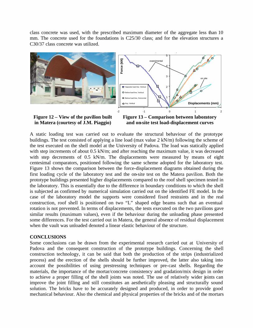
class concrete was used, with the prescribed maximum diameter of the aggregate less than 10 mm. The concrete used for the foundations is C25/30 class; and for the elevation structures a C30/37 class concrete was utilized.
Displacements : comparision laboratory test vs. on-site Matera test
0
1
2
3
4
5
-2 -1 0 1 2
Displacements (mm)
Fo
rce
(kN
)
Opposite load line, Vertical
Below load line, Vertical
Below load line, Horizontal
Key, Vertical
experimental
on site
Figure 12 – View of the pavilion built in Matera (courtesy of J.M. Piaggio)
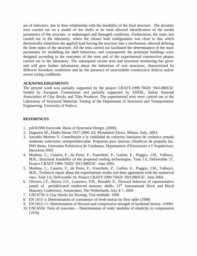
Figure 13 – Comparison between laboratory and on-site test load-displacement curves
A static loading test was carried out to evaluate the structural behaviour of the prototype buildings. The test consisted of applying a line load (max value 2 kN/m) following the scheme of the test executed on the shell model at the University of Padova. The load was statically applied with step increments of about 0.5 kN/m; and after reaching the maximum value, it was decreased with step decrements of 0.5 kN/m. The displacements were measured by means of eight centesimal comparators, positioned following the same scheme adopted for the laboratory test. Figure 13 shows the comparison between the force-displacement diagrams obtained during the first loading cycle of the laboratory test and the on-site test on the Matera pavilion. Both the prototype buildings presented higher displacements compared to the roof shell specimen tested in the laboratory. This is essentially due to the difference in boundary conditions to which the shell is subjected as confirmed by numerical simulation carried out on the identified FE model. In the case of the laboratory model the supports were considered fixed restraints and in the real construction, roof shell is positioned on two “L” shaped edge beams such that an eventual rotation is not prevented. In terms of displacements, the tests executed on the two pavilions gave similar results (maximum values), even if the behaviour during the unloading phase presented some differences. For the test carried out in Matera, the general absence of residual displacement when the vault was unloaded denoted a linear elastic behaviour of the structure. CONCLUSIONS Some conclusions can be drawn from the experimental research carried out at University of Padova and the consequent construction of the prototype buildings. Concerning the shell construction technology, it can be said that both the production of the strips (industrialized process) and the erection of the shells should be further improved, the latter also taking into account the possibilities of using prestressing techniques or pre-cast shells. Regarding the materials, the importance of the mortar/concrete consistency and gradation/mix design in order to achieve a proper filling of the shell joints was noted. The use of relatively wider joints can improve the joint filling and still constitutes an aesthetically pleasing and structurally sound solution. The bricks have to be accurately designed and produced, in order to provide good mechanical behaviour. Also the chemical and physical properties of the bricks and of the mortars
are of relevance, due to their relationship with the durability of the final structure. The dynamic tests carried out on a model of the shells to be built allowed identification of the modal parameters of the structure, in undamaged and damaged conditions. Furthermore, the static test carried out in the laboratory, where the chosen load configuration was close to that which theoretically minimizes the applied load forcing the structure into a mechanism, allowed defining the limit states of the structure. All the tests carried out facilitated the determination of the main parameters for modelling the shell behaviour, and consequently the prototype buildings were designed according to the outcomes of the tests and of the experimental constructive phases carried out in the laboratory. The subsequent on-site tests and structural monitoring has given and will give further information about the behaviour of real structures, characterized by different boundary conditions and by the presence of unavoidable constructive defects and/or severe curing conditions. ACKNOWLEDGEMENTS The present work was partially supported by the project CRAFT-1999-70420 ‘ISO-BRICK’ funded by European Commission and partially supported by ANDIL, Italian National Association of Clay Bricks and Tiles Producer. The experimental tests were carried out at the Laboratory of Structural Materials Testing of the Department of Structural and Transportation Engineering, University of Padova. REFERENCES 1. prEN1990 Eurocode: Basis of Structural Design. (2000). 2. Daguerre M., Eladio Dieste 1917-2000. Ed. Mondadori Electa. Milano, Italy. 2003. 3. Sarrablo Moreno V. Contributión a la viabilidad de cubiertas laminares de ceràmica armada
mediante soluciones semiprefabricadas. Propuesta para laminas cilìndricas de pequeña luz. PhD thesis, Univesitat Politécnica de Catalunya, Departament d’Estructures a l’Arquitectura. Barcelona 2002
4. Modena, C., Casarin, F., da Porto, F., Franchetti, P., Garbin, E., Piaggio, J.M., Valluzzi, M.R., Structural feasibility of the proposed roofing technologies. Task 1.6, Deliverable 17, Project CRAFT-1999-70420 ‘ISO-BRICK’. June 2004.
5. Modena, C., Casarin, F., da Porto, F., Franchetti, P., Garbin, E., Piaggio, J.M., Valluzzi, M.R., Technical report about the experimental results and their agreement with the numerical ones. Task 1.6, Deliverable 16, Project CRAFT-1999-70420 ‘ISO-BRICK’. June 2004.
6. Oliveira J.T., Barros J.O., Lourenco, P.B., Bonaldo E., Flexural behavior of representative panels of prefabricated reinforced masonry shells, 13th International Brick and Block Masonry Conference, Amsterdam, The Netherlands. July 4-7, 2004
7. UNI 9730-3: Clay blocks for flooring. Test methods. 1990 8. EN 1015-3: Determination of consistence of fresh mortar by flow table (1998) 9. EN 1015-11: Determination of flexural and compressive strength of hardened mortar. (1999) 10. UNI 6556: Tests of concretes – Determination of static modulus of elasticity in compression
(1976)