Embed Size (px)
Citation preview
DoepkeThe experts in residual current protection technology
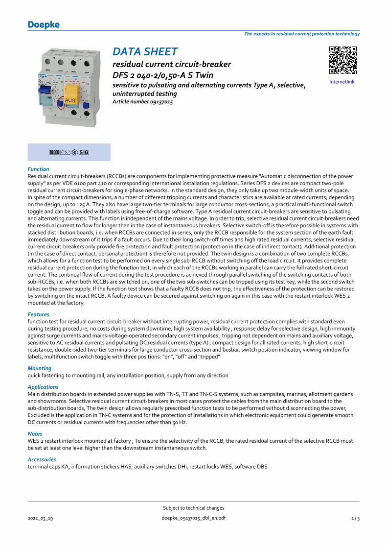
DATA SHEETresidual current circuit-breakerDFS 2 040-2/0,50-A S Twinsensitive to pulsating and alternating currents Type A, selective,uninterrupted testingArticle number 09137015
Internetlink
1ATsg
FunctionResidual current circuit-breakers (RCCBs) are components for implementing protective measure "Automatic disconnection of the powersupply" as per VDE 0100 part 410 or corresponding international installation regulations. Series DFS 2 devices are compact two-poleresidual current circuit-breakers for single-phase networks. In the standard design, they only take up two module-width units of space.In spite of the compact dimensions, a number of different tripping currents and characteristics are available at rated currents, dependingon the design, up to 125 A. They also have large two-tier terminals for large conductor cross-sections, a practical multi-functional switchtoggle and can be provided with labels using free-of-charge software. Type A residual current circuit-breakers are sensitive to pulsatingand alternating currents. This function is independent of the mains voltage. In order to trip, selective residual current circuit-breakers needthe residual current to flow for longer than in the case of instantaneous breakers. Selective switch-off is therefore possible in systems withstacked distribution boards, i.e. when RCCBs are connected in series, only the RCCB responsible for the system section of the earth faultimmediately downstream of it trips if a fault occurs. Due to their long switch-off times and high rated residual currents, selective residualcurrent circuit-breakers only provide fire protection and fault protection (protection in the case of indirect contact). Additional protection(in the case of direct contact, personal protection) is therefore not provided. The twin design is a combination of two complete RCCBs,which allows for a function test to be performed on every single sub-RCCB without switching off the load circuit. It provides completeresidual current protection during the function test, in which each of the RCCBs working in parallel can carry the full rated short-circuitcurrent. The continual flow of current during the test procedure is achieved through parallel switching of the switching contacts of bothsub-RCCBs, i.e. when both RCCBs are switched on, one of the two sub-switches can be tripped using its test key, while the second switchtakes on the power supply. If the function test shows that a faulty RCCB does not trip, the effectiveness of the protection can be restoredby switching on the intact RCCB. A faulty device can be secured against switching on again in this case with the restart interlock WES 2mounted at the factory.
Featuresfunction test for residual current circuit-breaker without interrupting power, residual current protection complies with standard evenduring testing procedure, no costs during system downtime, high system availability , response delay for selective design, high immunityagainst surge currents and mains-voltage-operated secondary current impulses , tripping not dependent on mains and auxiliary voltage,sensitive to AC residual currents and pulsating DC residual currents (type A) , compact design for all rated currents, high short-circuitresistance, double-sided two-tier terminals for large conductor cross-section and busbar, switch position indicator, viewing window forlabels, multifunction switch toggle with three positions: "on", "off" and "tripped"
Mountingquick fastening to mounting rail, any installation position, supply from any direction
ApplicationsMain distribution boards in extended power supplies with TN-S, TT and TN-C-S systems, such as campsites, marinas, allotment gardensand showrooms. Selective residual current circuit-breakers in most cases protect the cables from the main distribution board to thesub-distribution boards, The twin design allows regularly prescribed function tests to be performed without disconnecting the power,Excluded is the application in TN-C systems and for the protection of installations in which electronic equipment could generate smoothDC currents or residual currents with frequencies other than 50 Hz.
NotesWES 2 restart interlock mounted at factory , To ensure the selectivity of the RCCB, the rated residual current of the selective RCCB mustbe set at least one level higher than the downstream instantaneous switch.
Accessoriesterminal caps KA, information stickers HAS, auxiliary switches DHi, restart locks WES, software DBS
Subject to technical changes
2022_03_19 doepke_09137015_dbl_en.pdf 1 / 3
DoepkeThe experts in residual current protection technology
Technical Data
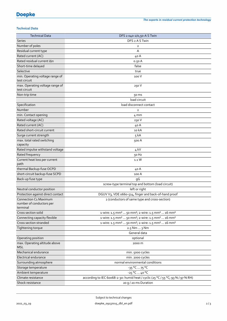
Technical Data DFS 2 040-2/0,50-A S TwinSeries DFS 2 A S TwinNumber of poles 2Residual current type ARated current (AC) 40 ARated residual current IΔn 0.50 AShort-time delayed falseSelective truemin. Operating voltage range oftest circuit
100 V
max. Operating voltage range oftest circuit
250 V
Non-trip time 50 msload circuit
Specification load disconnect contactNumber 2min. Contact opening 4 mmRated voltage (AC) 230 VRated current (AC) 40 ARated short-circuit current 10 kASurge current strength 5 kAmax. total rated switchingcapacity
500 A
Rated impulse withstand voltage 4 kVRated frequency 50 HzCurrent heat loss per currentpath
1.1 W
thermal Backup-fuse OCPD 40 Ashort-circuit backup-fuse SCPD 100 ABack-up fuse type gG
screw-type terminal top and bottom (load circuit)Neutral conductor position left or rightProtection against direct contact DGUV V3, VDE 0660-514, finger and back-of-hand proofConnection C1 Maximumnumber of conductors perterminal
2 (conductors of same type and cross-section)
Cross section solid 1-wire: 1.5 mm² ... 50 mm²; 2-wire: 1.5 mm² ... 16 mm²Connecting capacity flexible 1-wire: 1.5 mm² ... 50 mm²; 2-wire: 1.5 mm² ... 16 mm²Cross section stranded 1-wire: 1.5 mm² ... 50 mm²; 2-wire: 1.5 mm² ... 16 mm²Tightening torque 2.5 Nm ... 3 Nm
General dataOperating position optionalmax. Operating altitude aboveMSL
2000 m
Mechanical endurance min. 5000 cyclesElectrical endurance min. 2000 cyclesSurrounding atmosphere normal environmental conditionsStorage temperature -35 °C ... 75 °CAmbient temperature -25 °C ... 40 °CClimate resistance according to IEC 60068-2-30: humid heat / cyclic (25 °C / 55 °C; 93 % / 97 % RH)Shock resistance 20 g / 20 ms Duration
Subject to technical changes
2022_03_19 doepke_09137015_dbl_en.pdf 2 / 3
DoepkeThe experts in residual current protection technology
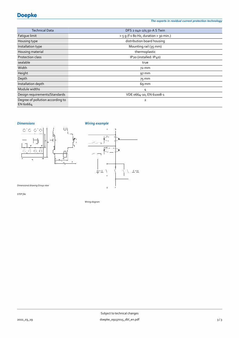
Technical Data DFS 2 040-2/0,50-A S TwinFatigue limit > 5 g (f ≤ 80 Hz, duration > 30 min.)Housing type distribution board housingInstallation type Mounting rail (35 mm)Housing material thermoplasticProtection class IP20 (installed: IP40)sealable trueWidth 72 mmHeight 97 mmDepth 75 mmInstallation depth 69 mmModule widths 4Design requirements/Standards VDE 0664-10, EN 61008-1Degree of pollution according toEN 60664
2
Dimensions Wiring example
Dimensional drawing Group view
STEP file
Wiring diagram
Subject to technical changes
2022_03_19 doepke_09137015_dbl_en.pdf 3 / 3