Embed Size (px)
Citation preview
Doepke UK Ltd Technical Publication 19
1 © 2019 -2021 CHAZ ANDREWS ALL RIGHTS RESERVED Doepke -RCD Testing Basics Oct 2019 v3
RCD Testing 18th Edition Basics Understanding the basics, helps us make reasoned decisions.
In practical situations and under time constraints, it is easy to lose sight of why we carry out specific tests on RCDs and under what conditions those tests may or may not be relevant. Understanding the basics of the subject, enables us to make reasoned decisions, when faced with an unfamiliar situation, application or an apparent problem.
When considering which tests to perform on an RCD think in terms of:
1. Functional tests – Regulation 643.10; to verify that the device will operate correctly under normal service conditions e.g. unwanted tripping due to an accumulation of leakage currents – see Earth Leakage Currents in the article.
2. Verification tests - Regulation 643.7, 643.7.1 (2) & 643.8; for effectiveness of protection measures e.g. Tests replicating residual fault current conditions – see Residual Fault Currents in the article.
3. Any specific requirements of the installation / application – see Regs, Section 7 and CoP.
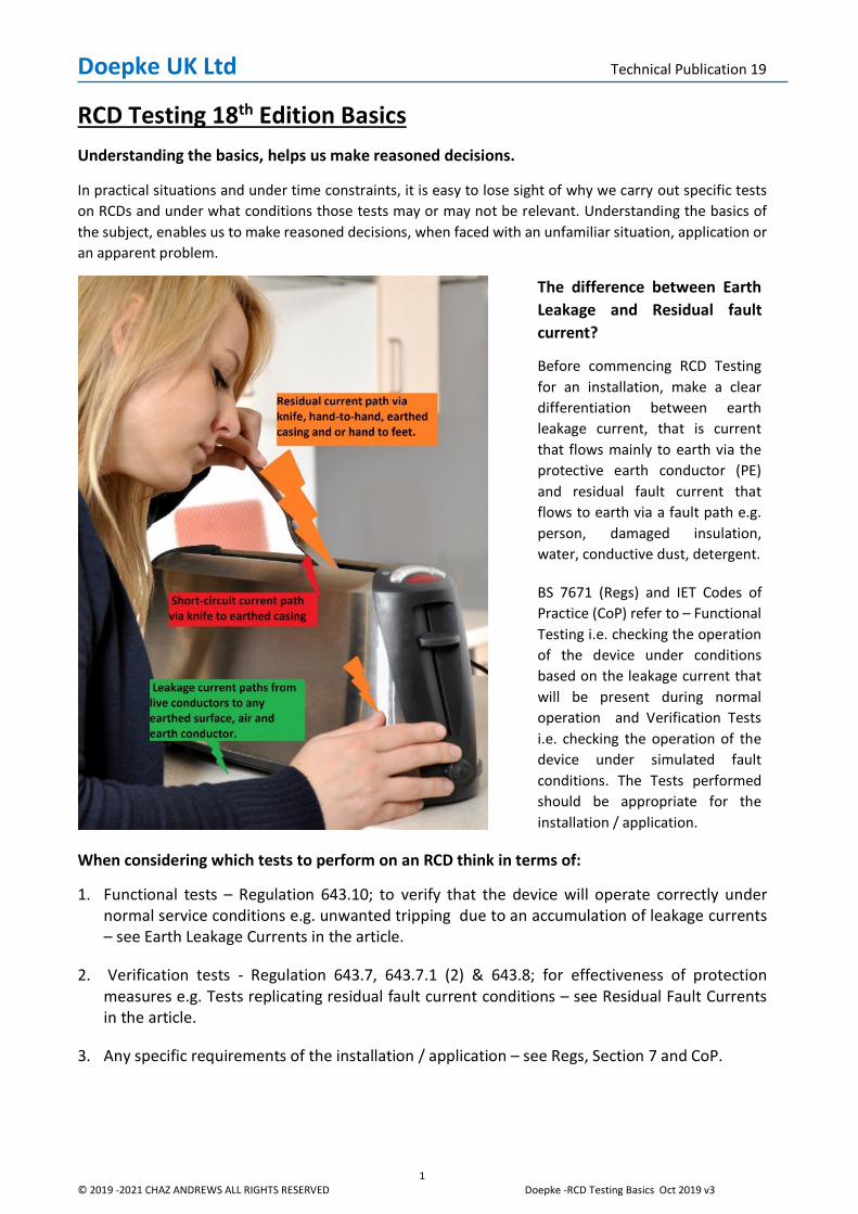
The difference between Earth Leakage and Residual fault current?
Before commencing RCD Testing for an installation, make a clear differentiation between earth leakage current, that is current that flows mainly to earth via the protective earth conductor (PE) and residual fault current that flows to earth via a fault path e.g. person, damaged insulation, water, conductive dust, detergent.
BS 7671 (Regs) and IET Codes of Practice (CoP) refer to – Functional Testing i.e. checking the operation of the device under conditions based on the leakage current that will be present during normal operation and Verification Tests i.e. checking the operation of the device under simulated fault conditions. The Tests performed should be appropriate for the installation / application.
Doepke UK Ltd Technical Publication 19
2 © 2019 -2021 CHAZ ANDREWS ALL RIGHTS RESERVED Doepke -RCD Testing Basics Oct 2019 v3
Earth leakage currents
All electrical circuits leak current due to natural (parasitic) capacitance between live conductors and earth and any capacitors contained in electrical appliances i.e. think of the leakage current as the level of current that flows to earth, when there are no insulation faults present in the circuit.
It must be taken into account as part of the circuit design parameters, for selection of RCDs, PE conductor sizing and PE conductor connection, based on the equipment leakage current – see Reg. 543.7
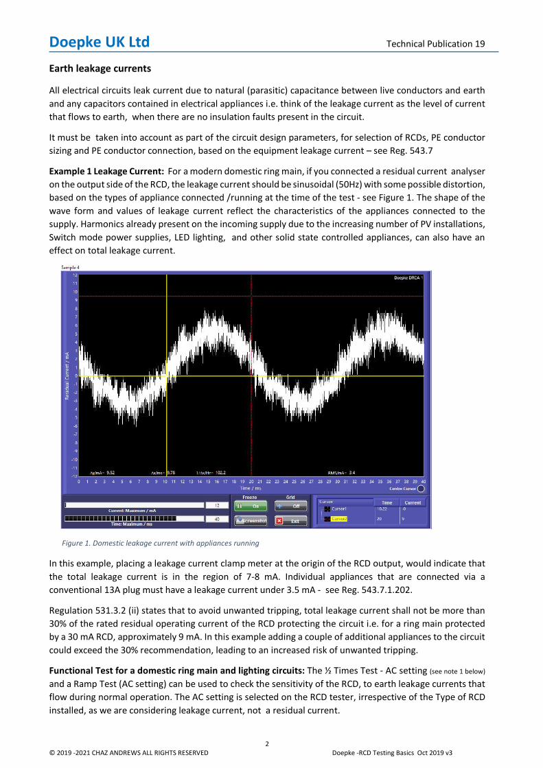
Example 1 Leakage Current: For a modern domestic ring main, if you connected a residual current analyser on the output side of the RCD, the leakage current should be sinusoidal (50Hz) with some possible distortion, based on the types of appliance connected /running at the time of the test - see Figure 1. The shape of the wave form and values of leakage current reflect the characteristics of the appliances connected to the supply. Harmonics already present on the incoming supply due to the increasing number of PV installations, Switch mode power supplies, LED lighting, and other solid state controlled appliances, can also have an effect on total leakage current.
Figure 1. Domestic leakage current with appliances running
In this example, placing a leakage current clamp meter at the origin of the RCD output, would indicate that the total leakage current is in the region of 7-8 mA. Individual appliances that are connected via a conventional 13A plug must have a leakage current under 3.5 mA - see Reg. 543.7.1.202.
Regulation 531.3.2 (ii) states that to avoid unwanted tripping, total leakage current shall not be more than 30% of the rated residual operating current of the RCD protecting the circuit i.e. for a ring main protected by a 30 mA RCD, approximately 9 mA. In this example adding a couple of additional appliances to the circuit could exceed the 30% recommendation, leading to an increased risk of unwanted tripping.
Functional Test for a domestic ring main and lighting circuits: The ½ Times Test - AC setting (see note 1 below) and a Ramp Test (AC setting) can be used to check the sensitivity of the RCD, to earth leakage currents that flow during normal operation. The AC setting is selected on the RCD tester, irrespective of the Type of RCD installed, as we are considering leakage current, not a residual current.
Doepke UK Ltd Technical Publication 19
3 © 2019 -2021 CHAZ ANDREWS ALL RIGHTS RESERVED Doepke -RCD Testing Basics Oct 2019 v3
These tests can help identify potential problems, where a circuit has a number of appliances running at the same time, or where there is an intermittent problem with an RCD tripping. With the introduction of RCD protection for lighting circuits and the use of more LED lighting per circuit (increased leakage currents) , this test may need to be considered for safety reasons i.e. nuisance tripping of an RCD protecting lighting in a stairways etc. When designing lighting installation which include LED lighting in kitchens, bathrooms allow for increased leakage current due to steam and humidity around lighting fittings.
Note 1: The standard value of residual non-operating current 0.5 I ∆n is based on Type AC current, not to be confused with Type A pulsed residual currents, where values of non-operating current depend on the
starting instant α i.e. 0°, 90°, 180° - see table further on in the article – RCCB Tripping Criteria.
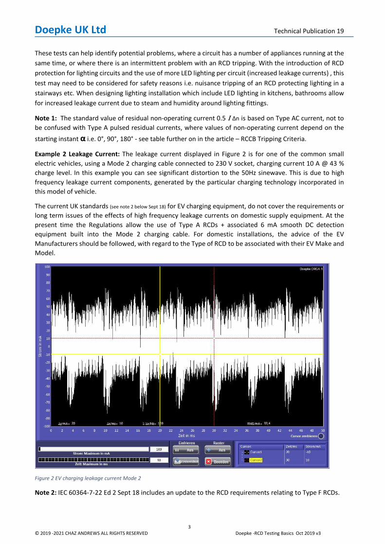
Example 2 Leakage Current: The leakage current displayed in Figure 2 is for one of the common small electric vehicles, using a Mode 2 charging cable connected to 230 V socket, charging current 10 A @ 43 % charge level. In this example you can see significant distortion to the 50Hz sinewave. This is due to high frequency leakage current components, generated by the particular charging technology incorporated in this model of vehicle.
The current UK standards (see note 2 below Sept 18) for EV charging equipment, do not cover the requirements or long term issues of the effects of high frequency leakage currents on domestic supply equipment. At the present time the Regulations allow the use of Type A RCDs + associated 6 mA smooth DC detection equipment built into the Mode 2 charging cable. For domestic installations, the advice of the EV Manufacturers should be followed, with regard to the Type of RCD to be associated with their EV Make and Model.
Figure 2 EV charging leakage current Mode 2
Note 2: IEC 60364-7-22 Ed 2 Sept 18 includes an update to the RCD requirements relating to Type F RCDs.
Doepke UK Ltd Technical Publication 19
4 © 2019 -2021 CHAZ ANDREWS ALL RIGHTS RESERVED Doepke -RCD Testing Basics Oct 2019 v3
Functional Test for an RCD associated with a Mode 2 charging socket: The CoP 3rd Edition for EV charging installations does not recommend any specific functional checks for RCDs – Ref. CoP 9.2.1.
The ½ x test may not be relevant to a dedicated circuit associated with a single charge point, as there are unlikely to be any safety issues related to unwanted tripping of the RCD – assuming the Vehicle is not being used by the Emergency Services.
Unstable supply voltage / harmonics may lead to nuisance tripping, as this will result in increased leakage currents and possible transients. A ramp test on the RCD is always a good starting point, when trying to solve problems with nuisance tripping. Remember, if you are carrying out a ramp test for a functional test, relating to operational leakage current, use the AC setting i.e. you are replicating the effect of an AC leakage current on the RCD under normal operating conditions – see comments below relating to residual fault currents.
For RCD verification tests - see CoP 5.6.1 and BS7671 643.7 and comments below.
Residual Fault Currents
First point; the term residual “fault” current has been used to focus the attention on the difference between currents that flow to earth during fault free operation (earth leakage) and currents that flow to earth under fault conditions (residual current) i.e. RCDs do not differentiate between earth leakage or residual fault currents, in the same way that a fuse does not differentiate between an overload or short-circuit current.
Second point; the location of the fault within a circuit or connected appliance and the characteristics of the appliance, will determine what Type of residual current flows through the RCD - see example 3.
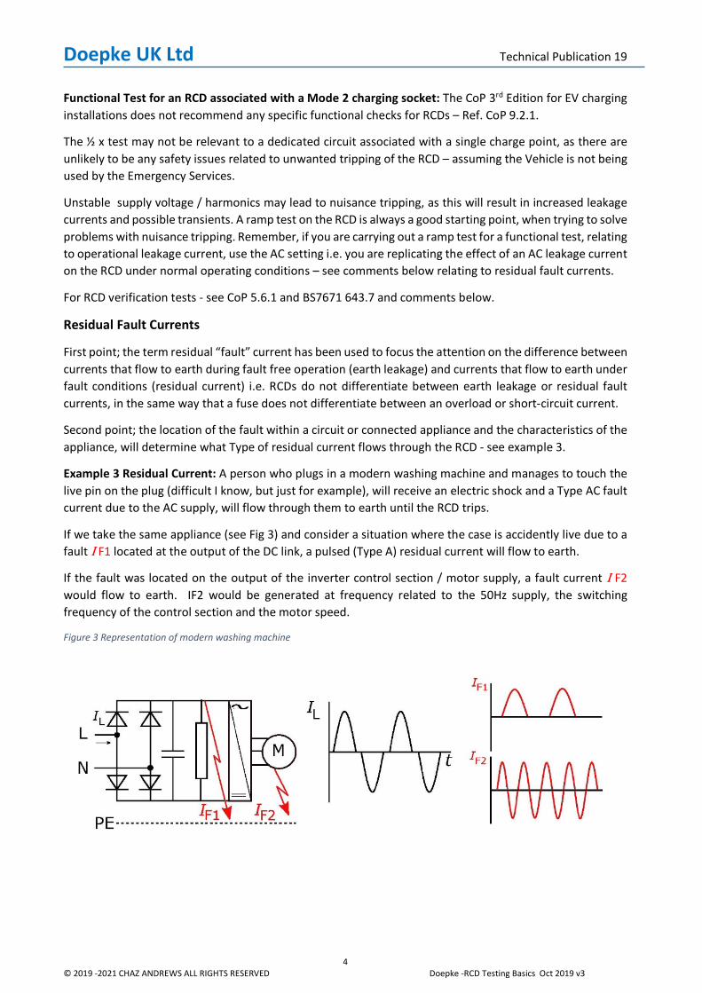
Example 3 Residual Current: A person who plugs in a modern washing machine and manages to touch the live pin on the plug (difficult I know, but just for example), will receive an electric shock and a Type AC fault current due to the AC supply, will flow through them to earth until the RCD trips.
If we take the same appliance (see Fig 3) and consider a situation where the case is accidently live due to a fault I F1 located at the output of the DC link, a pulsed (Type A) residual current will flow to earth.
If the fault was located on the output of the inverter control section / motor supply, a fault current I F2 would flow to earth. IF2 would be generated at frequency related to the 50Hz supply, the switching frequency of the control section and the motor speed.
Figure 3 Representation of modern washing machine
Doepke UK Ltd Technical Publication 19
5 © 2019 -2021 CHAZ ANDREWS ALL RIGHTS RESERVED Doepke -RCD Testing Basics Oct 2019 v3
RCD Verification tests Regulation 643.7
These tests are to verify that the RCD will perform effectively under the conditions required for protection. The selection of the test current is important when considering what protection function the RCD is performing.
Selecting a higher multiple of test current for fault protection, does not necessarily reflect the most dangerous situation. For example, if the RCD is providing fire protection – Reg. 422.3.9; the risk is from low values of sustained residual current across the surface of combustible materials. Studies shown that under certain conditions, currents below 100 mA can result in ignition of combustible materials. See Doepke Video
Testing at 1 x verifies that the RCD will disconnect within the required time, for low values of fault current i.e. 300 mA RCD providing fire protection is selected on the bases that a residual current of < 300 mA could flow for < 300 ms (Non-delay) or < 500 ms (Selective).
In this situation Testing at 5x is not that relevant, as it is the lower values of sustained residual current that pose the most risk. Note: The instrument must be suitable for testing Selective RCDs at the required value.
Conversely, RCDs providing additional protection – see Reg. 415.1.1); testing at 1 x and 5 x may be appropriate to verify the performance of the protection function, as a sustained value of low residual current could be as dangerous as a high value for a shorter duration. However, Regulation 643.8 does state that testing at 5 x is sufficient to prove effectiveness of the protection function.
A reminder about RCD Tripping thresholds: If you are going to be involved in installations where you regularly use different Types of RCD, it is worth spending a bit of time on the different tripping characteristics for these devises.
Note: BS7671 Appx. 3 Table 3A, is based on an AC Test Setting.
All RCCBs subjected to 50Hz AC residual current are designed to trip between 0.5-1I∆n. Type A,F,B: Pulsed residual current (50Hz, α=0°) tripping threshold changes to 0.35-1.4I∆n. Type A & F: Trip threshold is influenced by the smooth DC content (offset value) e.g.
Type A must still trip with < 6mA smooth DC superimposed on the pulsed waveform. Type F must still trip with < 10mA smooth DC superimposed on the pulsed waveform.
Type B: subjected to smooth DC residual current are designed to trip between 0.5-2I∆n.
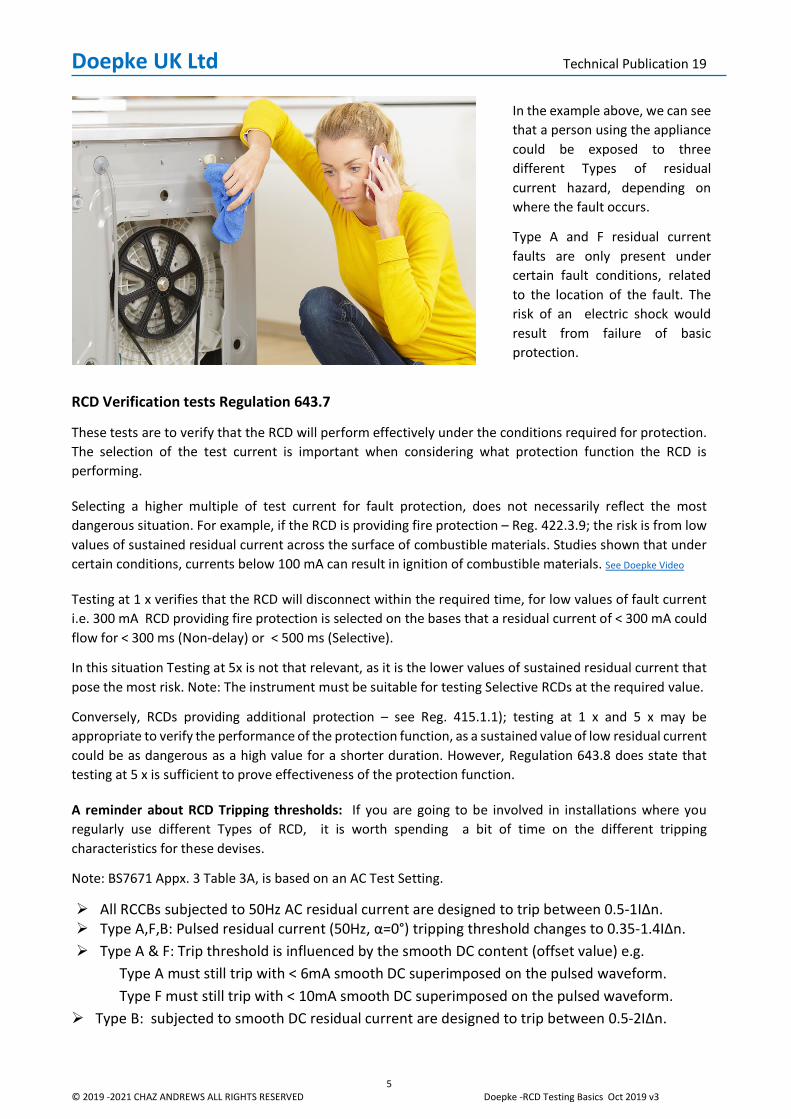
In the example above, we can see that a person using the appliance could be exposed to three different Types of residual current hazard, depending on where the fault occurs.
Type A and F residual current faults are only present under certain fault conditions, related to the location of the fault. The risk of an electric shock would result from failure of basic protection.
Doepke UK Ltd Technical Publication 19
6 © 2019 -2021 CHAZ ANDREWS ALL RIGHTS RESERVED Doepke -RCD Testing Basics Oct 2019 v3
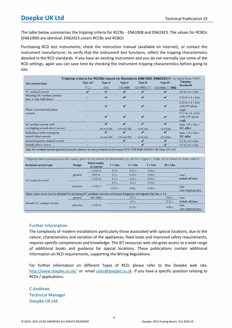
The table below summarises the tripping criteria for RCCBs - EN61008 and EN62423. The values for RCBOs (EN61009) are identical. EN62423 covers RCCBs and RCBOs
Purchasing RCD test instruments; check the instruction manual (available on internet), or contact the instrument manufacturer, to verify that the instrument test functions, reflect the tripping characteristics detailed in the RCD standards. If you have an existing instrument and you do not normally use some of the RCD settings, again you can save time by checking the instrument tripping characteristics before going to site.
Further Information The complexity of modern installations particularly those associated with special locations, due to the nature, characteristics and variation of the appliances, fixed loads and improved safety requirements, requires specific competences and knowledge. The IET resources web site gives access to a wide range of additional books and guidance for special locations. These publications contain additional information on RCD requirements, supporting the Wiring Regulations. For further information on different Types of RCD, please refer to the Doepke web site, http://www.doepke.co.uk/ or email [email protected] if you have a specific question relating to RCDs / applications.
C.Andrews Technical Manager Doepke UK Ltd