Embed Size (px)
Citation preview
1
New Series ofResidual Current Circuit Breakers
EFI-P
Thinking of safety - so you don’t have to
With automated 100% control of all keyparameters of each product
Reduced power dissipationby up to 45%
Increased reliability
2
Residual Current Circuit Breakers
Introduction
Since security is becoming more and more important due to better protection for humans, animals and higher fire safety, additional protection is being constantly developed and improved. This is where the Residual Current Circuit Breakers RCCBs come in.
Use of RCCBs is recommended where an increased risk of electrical shocks can appear (bathrooms, other humid and wet rooms, children’s rooms, workshops...). Protective residual current circuit breakers can be used in all systems, electrical installations, where neutral conductor (N conductor) and earth conductor (PE conductor) are separated. In old installations, in certain countries, where neutralization is still used, wherein the N and PE conductors are joined, such protection switch cannot be used.
Residual current devices are a commonly established way of protection against indirect contact with live parts, fires and direct contact with live parts in different types of installations. Performance is primarily related to grounding systems known as TT , TN and IT systems.
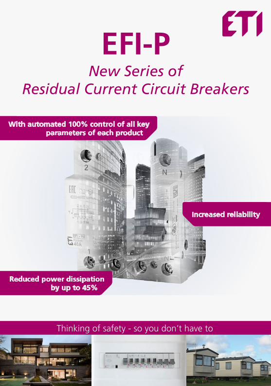
Operating principle of RCCB switches
In the case when the sum of incoming and outcoming currents through the primary winding is equal to 0, on the secondary side of the transformer the current will not be induced and the device will not switch off.
In the case, when the sum of incoming and outcoming currents through the primary winding is not equal to 0 and varies for the value of fault current IF current I2 is induced on the secondary winding and it triggers the RCCB through the relay.
3
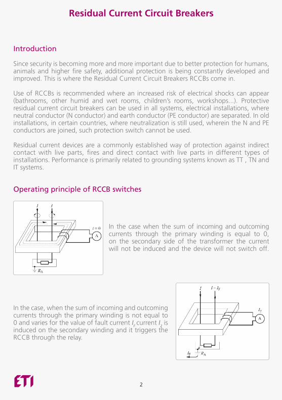
According to the sensitivity, there are three types of RCCBs for different protection as follows:aa ≤ 30mA : Protection against direct contact with live parts - “additional protection“aa ≤ 100mA : Protection against indirect contact with live parts - “basic protection“aa ≤ 300mA : fire protection
Technical requirements for residual current circuit breakers are prescribed in international standard IEC 61008 and European standard EN 61008. Main criteria for selection are as follows:aa Number of poles: 4 -pole , 2-poleaa Rated current : 16A , 25A , 40A , 63A , 80A , 100A , 125Aaa Rated Residual Current: 10 mA , 30 mA , 100mA , 300mA , 500mA ,aa Breaking times: instantaneous, short-time delayed , selectiveaa Type of residual current:
- pure sinus residual current, 50/60Hz: AC type - pure sinus and pulsating direct residual current, 50/60Hz: A type
Protection against direct contact with live parts - “additional protection“
L3L2L1NPE
2 N
1 N
RCCBI n 30 mA
Rc
It
RaRb
L3L2L1NPE
2 N
1 N
RCCBI n 30 mA
Rc
It
RaRb

4
Direct contact occurs when a human body directly touches live parts. If we assume that the resistance of human body is approximately 1kΩ, which off course depends on conductivity of human skin, then if we touch voltage of 230V, 230mA of current flows through our body. Such a current can already be life-threatening.
Influence of the current on human body:
10
100
1000
10000
0,1 1 10 100 1000
time
[ms]
Current through the body [mA]
RCD10mA 30mA
1 2 3 4
1: Area where influence is imperceptible 2: Area where there is no detectable adverse effects and muscle contraction 3: Area where muscle contraction can be detected, but there is no danger to the heart 4: Where you start having heart problems.
As you can see all RCCBs with rated residual current equal or less than 10mA are under the limit where influences on human body can occur. Because of that, they are especially suitable for use in bathrooms, children rooms, schools, hospitals, kindergartens…
RCCBs with residual current equal or less than 30mA are used for additional protection against electrical impacts.
5
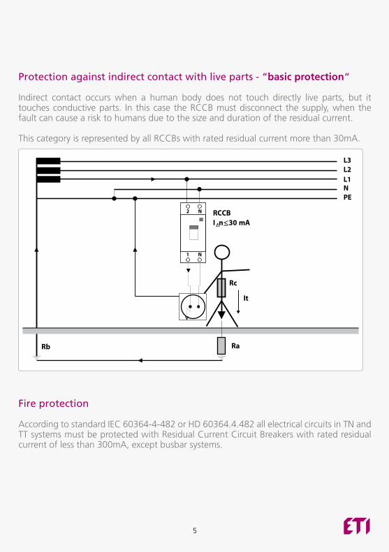
Protection against indirect contact with live parts - “basic protection“
Indirect contact occurs when a human body does not touch directly live parts, but it touches conductive parts. In this case the RCCB must disconnect the supply, when the fault can cause a risk to humans due to the size and duration of the residual current.
This category is represented by all RCCBs with rated residual current more than 30mA.
L3L2L1NPE
2 N
1 N
RCCBI n 30 mA
Rc
It
RaRb
L3L2L1NPE
2 N
1 N
RCCBI n 30 mA
Rc
It
RaRb
Fire protection
According to standard IEC 60364-4-482 or HD 60364.4.482 all electrical circuits in TN and TT systems must be protected with Residual Current Circuit Breakers with rated residual current of less than 300mA, except busbar systems.
6
Residual current circuit breakers - RCCBs
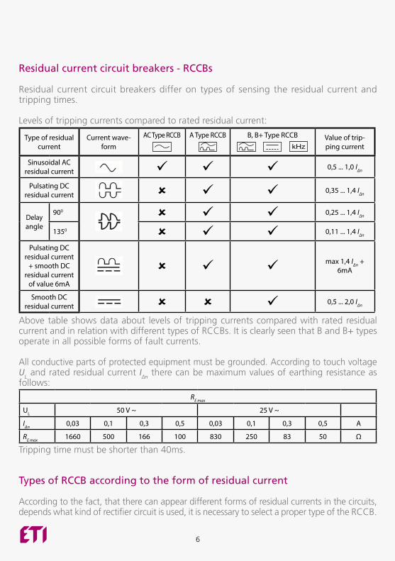
Residual current circuit breakers differ on types of sensing the residual current and tripping times.
Levels of tripping currents compared to rated residual current:
Type of residual current
Current wave-form
AC Type RCCB A Type RCCB
B, B+ Type RCCB
a a
Value of trip-ping current
Sinusoidal AC residual current
0,5 ... 1,0 IΔn
Pulsating DC residual current
0,35 ... 1,4 IΔn
Delay angle
900
0,25 ... 1,4 IΔn
1350 0,11 ... 1,4 IΔn
Pulsating DC residual current
+ smooth DC residual current
of value 6mA
max 1,4 IΔn + 6mA
Smooth DC residual current 0,5 ... 2,0 IΔn
Above table shows data about levels of tripping currents compared with rated residual current and in relation with different types of RCCBs. It is clearly seen that B and B+ types operate in all possible forms of fault currents.
All conductive parts of protected equipment must be grounded. According to touch voltage UL and rated residual current IΔn there can be maximum values of earthing resistance as follows:
RE max
UL 50 V ~ 25 V ~
IΔn 0,03 0,1 0,3 0,5 0,03 0,1 0,3 0,5 A
RE max 1660 500 166 100 830 250 83 50 Ω
Tripping time must be shorter than 40ms.
Types of RCCB according to the form of residual current
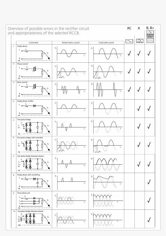
According to the fact, that there can appear different forms of residual currents in the circuits, depends what kind of rectifier circuit is used, it is necessary to select a proper type of the RCCB.
7
Single phase rectifier
L
NPE
IL
IF
Single phase with smoothing
L
NPE
IL
IF
IF
IF
t
IF
t
IL
t
Three-phase star
L
NPE
IL
IF
1
L2L3
Two-pulse bridge
LN
PE
IL
IF
Two-pulse bridge, half controlled
LN
PE
ILIF
Two-pulse bridge between phases
LL
PE
IL
IF1
2N
Phase control
L
NPE
IL
IF
Burst control
L
NPE
IL
IF
tnerruchtraetluaFtnerrucsniamlamroNnoitcennoC
AC A B, B+
4
8
9
5
6
7
2
3
IL
t
IL
t
IF
t
IL
t
IF
t
t
IL
IF
t
IL
t
IF
t
IL
t
IF
IL
t
t
IF
tt
IL
L
NPE
IL
IF
IL
t
IF
t
1
10
Single phase
Six-pulse bridge between phases
Overview of possible errors in the rectifier circuit and appropriateness of the selected RCCB.
8
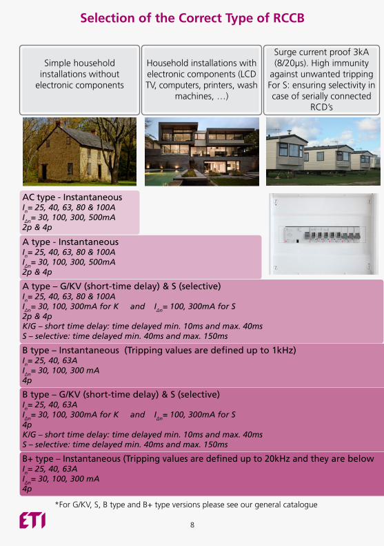
Simple household
installations without electronic components
Household installations with electronic components (LCD TV, computers, printers, wash
machines, …)
Surge current proof 3kA (8/20μs). High immunity
against unwanted tripping For S: ensuring selectivity in case of serially connected
RCD’s
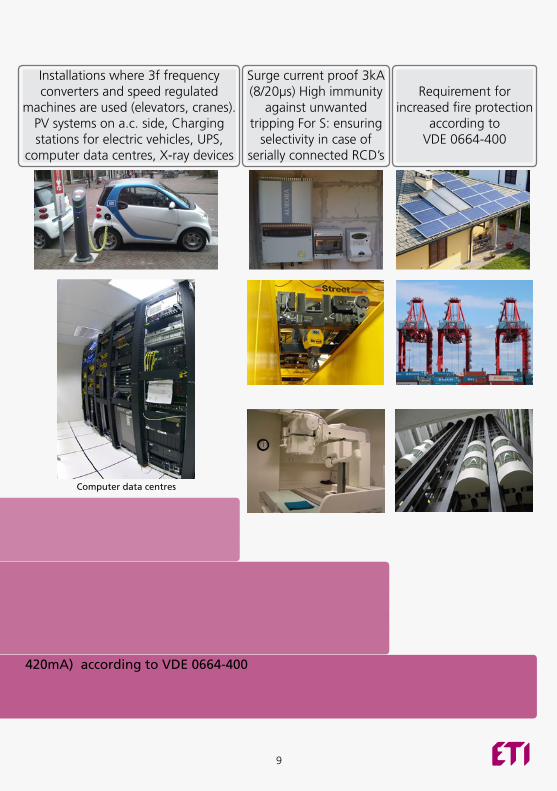
Installations where 3f frequency converters and speed regulated
machines are used (elevators, cranes). PV systems on a.c. side, Charging stations for electric vehicles, UPS,
computer data centres, X-ray devices
Surge current proof 3kA (8/20μs) High immunity
against unwanted tripping For S: ensuring
selectivity in case of serially connected RCD’s
Requirement for
increased fire protection according to
VDE 0664-400
AC type - Instantaneous In= 25, 40, 63, 80 & 100A I∆n= 30, 100, 300, 500mA 2p & 4p
Computer data centres
A type - Instantaneous In= 25, 40, 63, 80 & 100A I∆n= 30, 100, 300, 500mA 2p & 4p
A type – G/KV (short-time delay) & S (selective)In= 25, 40, 63, 80 & 100AI∆n= 30, 100, 300mA for K and I∆n= 100, 300mA for S 2p & 4pK/G – short time delay: time delayed min. 10ms and max. 40msS – selective: time delayed min. 40ms and max. 150ms
B type – Instantaneous (Tripping values are defined up to 1kHz)In= 25, 40, 63AI∆n= 30, 100, 300 mA4p
B type – G/KV (short-time delay) & S (selective)In= 25, 40, 63AI∆n= 30, 100, 300mA for K and I∆n= 100, 300mA for S 4pK/G – short time delay: time delayed min. 10ms and max. 40msS – selective: time delayed min. 40ms and max. 150ms
B+ type – Instantaneous (Tripping values are defined up to 20kHz and they are below 420mA) according to VDE 0664-400In= 25, 40, 63AI∆n= 30, 100, 300 mA4p
Selection of the Correct Type of RCCB
*For G/KV, S, B type and B+ type versions please see our general catalogue
9
Simple household
installations without electronic components
Household installations with electronic components (LCD TV, computers, printers, wash
machines, …)
Surge current proof 3kA (8/20μs). High immunity
against unwanted tripping For S: ensuring selectivity in case of serially connected
RCD’s
Installations where 3f frequency converters and speed regulated
machines are used (elevators, cranes). PV systems on a.c. side, Charging stations for electric vehicles, UPS,
computer data centres, X-ray devices
Surge current proof 3kA (8/20μs) High immunity
against unwanted tripping For S: ensuring
selectivity in case of serially connected RCD’s
Requirement for
increased fire protection according to
VDE 0664-400
AC type - Instantaneous In= 25, 40, 63, 80 & 100A I∆n= 30, 100, 300, 500mA 2p & 4p
Computer data centres
A type - Instantaneous In= 25, 40, 63, 80 & 100A I∆n= 30, 100, 300, 500mA 2p & 4p
A type – G/KV (short-time delay) & S (selective)In= 25, 40, 63, 80 & 100AI∆n= 30, 100, 300mA for K and I∆n= 100, 300mA for S 2p & 4pK/G – short time delay: time delayed min. 10ms and max. 40msS – selective: time delayed min. 40ms and max. 150ms
B type – Instantaneous (Tripping values are defined up to 1kHz)In= 25, 40, 63AI∆n= 30, 100, 300 mA4p
B type – G/KV (short-time delay) & S (selective)In= 25, 40, 63AI∆n= 30, 100, 300mA for K and I∆n= 100, 300mA for S 4pK/G – short time delay: time delayed min. 10ms and max. 40msS – selective: time delayed min. 40ms and max. 150ms
B+ type – Instantaneous (Tripping values are defined up to 20kHz and they are below 420mA) according to VDE 0664-400In= 25, 40, 63AI∆n= 30, 100, 300 mA4p
10
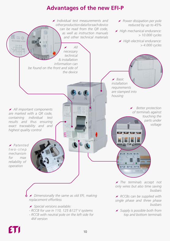
Advantages of the new EFI-P
aa All necessary technical
& installation information can
be found on the front and side of the device
aa Individual test measurements and other production data for each device
can be read from the QR code, as well as instruction manuals and other technical materials
aa Basic installation requirements are stamped into housing
aa Better protection of terminals against
touching the parts under
voltage
aa All important components are marked with a QR code, containing individual test results and thus ensuring exact traceability and and highest quality control
aa Patented t w o - s t e p mechanism for max reliability of operation
aa The terminals accept not only wires but also time saving
busbars
aa Supply is possible both from top and bottom terminals
aa RCCBs can be supplied with single phase and three phase
busbars aa Special versions available: - RCCB for use in 110, 125 &127 V systems - RCCB with neutral pole on the left side for
4M version
aa Dimensionally the same as old EFI, making replacement effortless
aa Power dissipation per pole reduced by up to 45%
aa High mechanical endurance: > 10.000 cycles
aa High electrical endurance: > 4.000 cycles
11
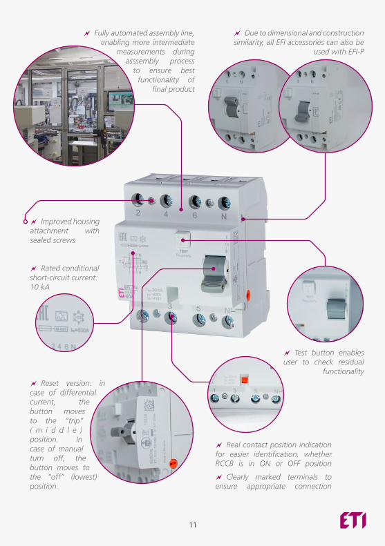
aa Improved housing attachment with sealed screws
aa Rated conditional short-circuit current: 10 kA
aa Fully automated assembly line, enabling more intermediate
measurements during asssembly process
to ensure best functionality of
final product
aa Test button enables user to check residual
functionality
aa Reset version: in case of differential current, the button moves to the “trip” ( m i d d l e ) position. In case of manual turn off, the button moves to the “off” (lowest) position.
aa Due to dimensional and construction similarity, all EFI accessories can also be
used with EFI-P
aa Real contact position indication for easier identification, whether RCCB is in ON or OFF position
aa Clearly marked terminals to ensure appropriate connection
12
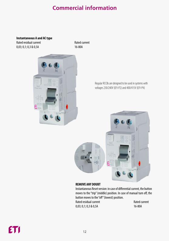
Commercial information
REMOVE ANY DOUBT Instantaneous Reset version: in case of differential current, the button moves to the “trip” (middle) position. In case of manual turn off, the button moves to the “off” (lowest) position.Rated residual current Rated current0,03; 0,1; 0,3 & 0,5A 16-80A
Instantaneous A and AC typeRated residual current Rated current0,03; 0,1; 0,3 & 0,5A 16-80A
Regular RCCBs are designed to be used in systems with voltages 230/240V (EFI-P2) and 400/415V (EFI-P4)
13
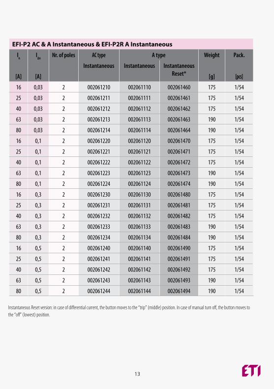
EFI-P2 AC & A Instantaneous & EFI-P2R A Instantaneous
ln I∆n Nr. of poles AC type A type Weight Pack.
Instantaneous Instantaneous Instantaneous Reset*[A] [A] [g] [pcs]
16 0,03 2 002061210 002061110 002061460 175 1/54
25 0,03 2 002061211 002061111 002061461 175 1/54
40 0,03 2 002061212 002061112 002061462 175 1/54
63 0,03 2 002061213 002061113 002061463 190 1/54
80 0,03 2 002061214 002061114 002061464 190 1/54
16 0,1 2 002061220 002061120 002061470 175 1/54
25 0,1 2 002061221 002061121 002061471 175 1/54
40 0,1 2 002061222 002061122 002061472 175 1/54
63 0,1 2 002061223 002061123 002061473 190 1/54
80 0,1 2 002061224 002061124 002061474 190 1/54
16 0,3 2 002061230 002061130 002061480 175 1/54
25 0,3 2 002061231 002061131 002061481 175 1/54
40 0,3 2 002061232 002061132 002061482 175 1/54
63 0,3 2 002061233 002061133 002061483 190 1/54
80 0,3 2 002061234 002061134 002061484 190 1/54
16 0,5 2 002061240 002061140 002061490 175 1/54
25 0,5 2 002061241 002061141 002061491 175 1/54
40 0,5 2 002061242 002061142 002061492 175 1/54
63 0,5 2 002061243 002061143 002061493 190 1/54
80 0,5 2 002061244 002061144 002061494 190 1/54
Instantaneous Reset version: in case of differential current, the button moves to the “trip” (middle) position. In case of manual turn off, the button moves to the “off” (lowest) position.
14
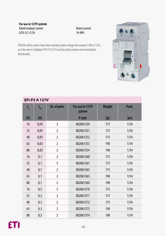
EFI-P2 A 127V
ln I∆n Nr. of poles For use in 127V system
Weight Pack.
[A] [A] A type [g] [pcs]
16 0,03 2 002061350 175 1/54
25 0,03 2 002061351 175 1/54
40 0,03 2 002061352 175 1/54
63 0,03 2 002061353 190 1/54
80 0,03 2 002061354 190 1/54
16 0,1 2 002061360 175 1/54
25 0,1 2 002061361 175 1/54
40 0,1 2 002061362 175 1/54
63 0,1 2 002061363 190 1/54
80 0,1 2 002061364 190 1/54
16 0,3 2 002061370 175 1/54
25 0,3 2 002061371 175 1/54
40 0,3 2 002061372 175 1/54
63 0,3 2 002061373 190 1/54
80 0,3 2 002061374 190 1/54
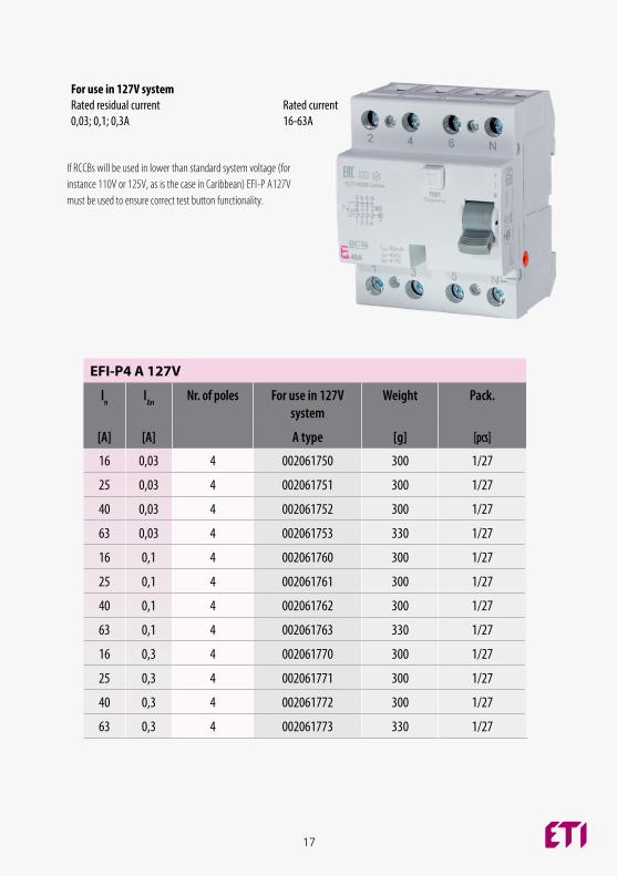
For use in 127V systemRated residual current Rated current0,03; 0,1; 0,3A 16-80A
If RCCBs will be used in lower than standard system voltage (for instance 110V or 125V, as is the case in Caribbean) EFI-P A127V must be used to ensure correct test button functionality.
15
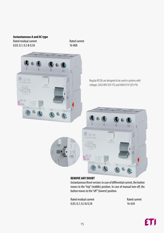
REMOVE ANY DOUBT Instantaneous Reset version: in case of differential current, the button moves to the “trip” (middle) position. In case of manual turn off, the button moves to the “off” (lowest) position.
Rated residual current Rated current0,03; 0,1; 0,3 & 0,5A 16-63A
Instantaneous A and AC typeRated residual current Rated current0,03; 0,1; 0,3 & 0,5A 16-80A
Regular RCCBs are designed to be used in systems with voltages 230/240V (EFI-P2) and 400/415V (EFI-P4)
16
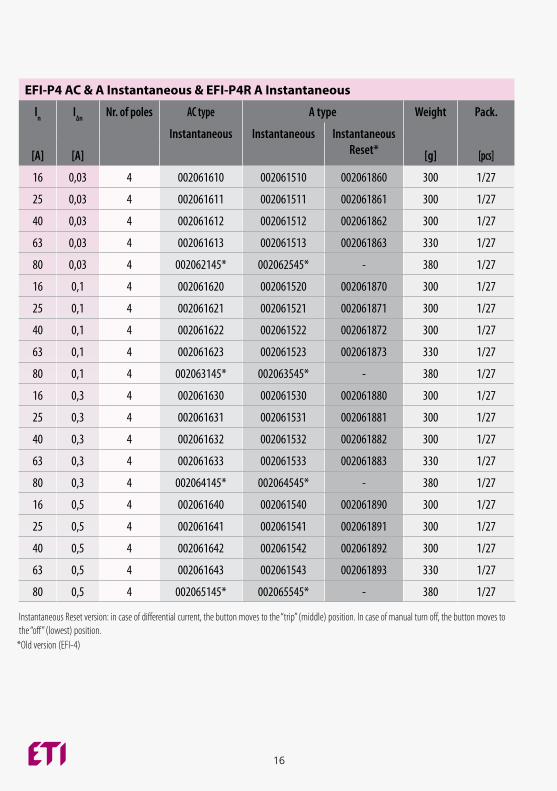
EFI-P4 AC & A Instantaneous & EFI-P4R A Instantaneous
ln I∆n Nr. of poles AC type A type Weight Pack.
Instantaneous Instantaneous Instantaneous Reset*[A] [A] [g] [pcs]
16 0,03 4 002061610 002061510 002061860 300 1/27
25 0,03 4 002061611 002061511 002061861 300 1/27
40 0,03 4 002061612 002061512 002061862 300 1/27
63 0,03 4 002061613 002061513 002061863 330 1/27
80 0,03 4 002062145* 002062545* - 380 1/27
16 0,1 4 002061620 002061520 002061870 300 1/27
25 0,1 4 002061621 002061521 002061871 300 1/27
40 0,1 4 002061622 002061522 002061872 300 1/27
63 0,1 4 002061623 002061523 002061873 330 1/27
80 0,1 4 002063145* 002063545* - 380 1/27
16 0,3 4 002061630 002061530 002061880 300 1/27
25 0,3 4 002061631 002061531 002061881 300 1/27
40 0,3 4 002061632 002061532 002061882 300 1/27
63 0,3 4 002061633 002061533 002061883 330 1/27
80 0,3 4 002064145* 002064545* - 380 1/27
16 0,5 4 002061640 002061540 002061890 300 1/27
25 0,5 4 002061641 002061541 002061891 300 1/27
40 0,5 4 002061642 002061542 002061892 300 1/27
63 0,5 4 002061643 002061543 002061893 330 1/27
80 0,5 4 002065145* 002065545* - 380 1/27
Instantaneous Reset version: in case of differential current, the button moves to the “trip” (middle) position. In case of manual turn off, the button moves to the “off” (lowest) position.
*Old version (EFI-4)
17
EFI-P4 A 127V
ln I∆n Nr. of poles For use in 127V system
Weight Pack.
[A] [A] A type [g] [pcs]
16 0,03 4 002061750 300 1/27
25 0,03 4 002061751 300 1/27
40 0,03 4 002061752 300 1/27
63 0,03 4 002061753 330 1/27
16 0,1 4 002061760 300 1/27
25 0,1 4 002061761 300 1/27
40 0,1 4 002061762 300 1/27
63 0,1 4 002061763 330 1/27
16 0,3 4 002061770 300 1/27
25 0,3 4 002061771 300 1/27
40 0,3 4 002061772 300 1/27
63 0,3 4 002061773 330 1/27
For use in 127V systemRated residual current Rated current0,03; 0,1; 0,3A 16-63A
If RCCBs will be used in lower than standard system voltage (for instance 110V or 125V, as is the case in Caribbean) EFI-P A127V must be used to ensure correct test button functionality.
18
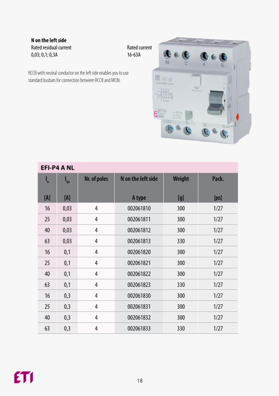
EFI-P4 A NL
ln I∆n Nr. of poles N on the left side Weight Pack.
[A] [A] A type [g] [pcs]
16 0,03 4 002061810 300 1/27
25 0,03 4 002061811 300 1/27
40 0,03 4 002061812 300 1/27
63 0,03 4 002061813 330 1/27
16 0,1 4 002061820 300 1/27
25 0,1 4 002061821 300 1/27
40 0,1 4 002061822 300 1/27
63 0,1 4 002061823 330 1/27
16 0,3 4 002061830 300 1/27
25 0,3 4 002061831 300 1/27
40 0,3 4 002061832 300 1/27
63 0,3 4 002061833 330 1/27
N on the left sideRated residual current Rated current0,03; 0,1; 0,3A 16-63A
RCCB with neutral conductor on the left side enables you to use standard busbars for connection between RCCB and MCBs
19
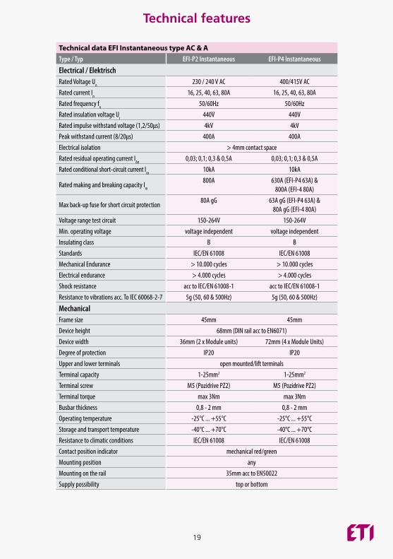
Technical data EFI Instantaneous type AC & AType / Typ EFI-P2 Instantaneous EFI-P4 Instantaneous
Electrical / ElektrischRated Voltage Un 230 / 240 V AC 400/415V ACRated current In 16, 25, 40, 63, 80A 16, 25, 40, 63, 80ARated frequency fn 50/60Hz 50/60HzRated insulation voltage Ui 440V 440VRated impulse withstand voltage (1,2/50μs) 4kV 4kVPeak withstand current (8/20μs) 400A 400A Electrical isolation > 4mm contact spaceRated residual operating current I∆n 0,03; 0,1; 0,3 & 0,5A 0,03; 0,1; 0,3 & 0,5A Rated conditional short-circuit current Icn 10kA 10kA
Rated making and breaking capacity Im
800A 630A (EFI-P4 63A) & 800A (EFI-4 80A)
Max back-up fuse for short circuit protection80A gG 63A gG (EFI-P4 63A) &
80A gG (EFI-4 80A)Voltage range test circuit 150-264V 150-264VMin. operating voltage voltage independent voltage independentInsulating class B BStandards IEC/EN 61008 IEC/EN 61008Mechanical Endurance > 10.000 cycles > 10.000 cyclesElectrical endurance > 4.000 cycles > 4.000 cyclesShock resistance acc to IEC/EN 61008-1 acc to IEC/EN 61008-1Resistance to vibrations acc. To IEC 60068-2-7 5g (50, 60 & 500Hz) 5g (50, 60 & 500Hz)
MechanicalFrame size 45mm 45mmDevice height 68mm (DIN rail acc to EN6071)Device width 36mm (2 x Module units) 72mm (4 x Module Units)Degree of protection IP20 IP20Upper and lower terminals open mounted/lift terminalsTerminal capacity 1-25mm2 1-25mm2
Terminal screw M5 (Pozidrive PZ2) M5 (Pozidrive PZ2)Terminal torque max 3Nm max 3NmBusbar thickness 0,8 - 2 mm 0,8 - 2 mmOperating temperature -25°C ... +55°C -25°C ... +55°CStorage and transport temperature -40°C ... +70°C -40°C ... +70°CResistance to climatic conditions IEC/EN 61008 IEC/EN 61008Contact position indicator mechanical red/greenMounting position anyMounting on the rail 35mm acc to EN50022Supply possibility top or bottom
Technical features
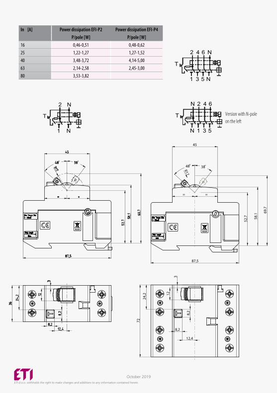
In [A] Power dissipation EFI-P2 Power dissipation EFI-P4P/pole [W] P/pole [W]
16 0,46-0,51 0,48-0,6225 1,22-1,27 1,27-1,5240 3,48-3,72 4,14-5,0063 2,14-2,58 2,45-3,0080 3,53-3,82
2
N1
N
T
6 N
5 N
T
42
31
6
5
T
42
31
N
N
45
52.7
3
72
12
87,5
= =
3848
69.
7
8,2
8,2
24,2
R17
58.
1
12,4
ETI d.o.o. withholds the right to make changes and additions to any information contained herein.
2
N1
N
T
6 N
5 N
T
42
31
6
5
T
42
31
N
N
October 2019
2
N1
N
T
6 N
5 N
T
42
31
6
5
T
42
31
N
N
Version with N-pole on the left