Embed Size (px)
Citation preview
2/1
Residual Current Circuit Breakers2 Residual Current Circuit Breakers
Who “nose” where his fingerwill be tomorrow!
2/1
2/2 Design, Construction &Features
2/8 Recommendations for RCCBSelection
2/9 Technical Specifications
2/10 Product Overview
2/15 Additional Components
2/16 Dimensions
2/2
Residual Current Circuit Breakers
Design, Construction & Features
General:
Electricity is usually taken for granted, but any imprudencecould be fatal. Damaged insulation and faulty wiring causea ‘Leakage current’ to flow to earth. Due to leakagecurrents, everyday activities like ironing, using a geyser,washing machine, a hair-dryer, an air-conditioner orindustrial machinery etc. could turn out to be potentiallylethal.
In addition, leakage currents of about 300-500 mA arecapable of causing electrical sparks that could causehazardous fire.
Minigard RCCB is the safest device to detect and trip onleakages and thereby offer instant protection againstelectrocution and electrical fire. In addition, they preventenergy wastage and thus save on electricity costs.
Dangers of Leakage Currents:
1. Direct / Indirect contact with a live parts
2. Electrical fires
3. Energy wastage
The solution:
30mA: Offers the highest level of protection to human andanimal life against direct and indirect contact with liveparts.
Recommended for residences, commercial and industrialpremises, power sockets, schools, hotels etc, wet areas andduring temporary construction installation. Siemens RCCBstrip between 10 to 30 ms, which is nearly 10 times fasterthan IEC requirements of 200 ms.
100mA: Normally provides protection only against indirectcontact and hence protects both the entire wiring systemand components e.g. in buildings, laboratories, industry,workshops etc. for faults caused through misuse,accidental damage or appliance failure.
300mA: Used where only fire protection is required andrisk of electric shock is small. It is normal to use 300mA asincomer and subsequent 30mA/100mA protective RCCBs inthe downstream circuit.
Types of Residual Current Protection Devices
1. Type AC
2. Type A
3. Type B
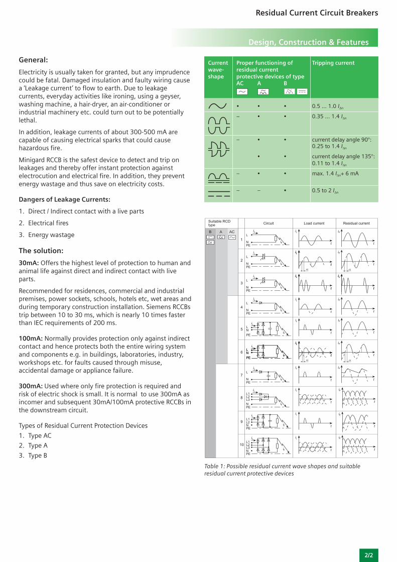
Current Proper functioning of Tripping currentwave- residual currentshape protective devices of type
AC A B
• • • 0.5 ... 1.0 IΔn
– • • 0.35 ... 1.4 IΔn
– • • current delay angle 90°:0.25 to 1.4 IΔn
• • current delay angle 135°:0.11 to 1.4 IΔn
– • • max. 1.4 IΔn+ 6 mA
– – • 0.5 to 2 IΔn
Table 1: Possible residual current wave shapes and suitableresidual current protective devices
Type , Short Time- Delayed
As far as the device specification is concerned, there areonly two device versions: instantaneous and selective. The“K” versions must therefore fulfill the maximum permissibletripping times for instantaneous devices. Residual currentprotective devices of type are slightly delayed (approx. 10ms for high residual currents).
The tripping times for the “K” versions are thereforesomewhat longer as those for the standard devices, forexample for residual currents > 5 IΔn: approx. 30 msinstead of around 10 to 15 ms.
They therefore conform to the maximum permissibletripping times (40 ms) for the standard versions (see Figure2). They are identified by the symbol .
The layout of the tripping circuit reduces the electricalinterference of transient residual currents. This results in anincreased surge withstand strength of 3 kA (8/20 μs currentwaveform, see Figure below) compared to the standardversion (1 kA). In addition, these RCCB s are insensitive tosurge leakage currents, such as those which occur inswitched-mode power supplies or filters when capacitorsare switched on.
Type B:
In addition to detecting residual current waveforms of typeA, residual current protective devices of type B are used tomeasure smooth DC residual currents. Residual currentoperated circuit breakers of this type are suitable for use inthree-phase AC systems with 50/60 Hz also upstream ofinput circuits No. 7 to 10 in Table 1 and therefore for all thecircuits shown.
Breaking capacity:
Every RCCB requires suitable rating backup fuse in order toachieve required breaking capacity. When used along witha MCB ≥ 10kA, no additional back-up fuse is required andare suitable for a network having a prospective short circuitcurrent of 10 kA. (e.g. 5SX4 MCBs)
2/3
Residual Current Circuit Breakers
Design, Construction & Features
Type AC:
Residual current protective devices of type AC are suitableonly for detecting sinusoidal AC residual current (seecircuits 1 to 3 in Table 1). This device type to DIN VDE0100-530 is not authorized in Germany for residual currentprotection, and cannot carry the VDE mark of conformity.
Type A:
In addition to sinusoidal AC residual currents, residualcurrent protective devices of type A also measure pulsatingDC residual currents.
This device type is the most commonly used pulse current-sensitive residual current operated circuit-breaker. It alsocovers the residual current waveforms which can occur inpower supply units (e.g. ECG, washing machines) in thecase of single-phase loads with electronic components.This type of residual current protective device is suitable forelectronic resources with input current circuits nos. 1 to 6in Table 1.
There are further sub types in Type A RCCB s. They are asfollows
Type S, Selective
Type K, Super Resistant
Type S Selective
In order to achieve selective tripping in the case of series-connected residual current protective devices in the eventof a fault scenario, both the rated residual current IΔn andthe tripping time of the devices must be staggered. Thedifferent permissible tripping times of the standard andselective residual current protective devices can be takenfrom Figure 1. The suitable staggering of the rated residualcurrents can also be seen in Figure below.
Selective residual current protective devices of type alsohave a very high surge withstand capability of 5 kA (8/20μs current waveform). They are identified by the symbol .
Figure 1: Layout of different residual current protective devicesand their tripping times
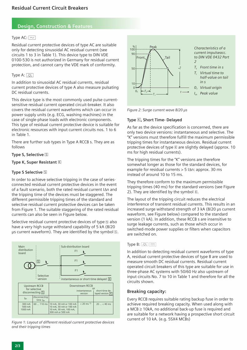
Figure 2: Surge current wave 8/20 μs
Characteristics of acurrent impulseacc.to DIN VDE 0432 Part2
Ts Front time in s
Tr Virtual time tohalf-value on tailin s
01 Virtual origin
Im Peak value
2/4
Residual Current Circuit Breakers
Design, Construction & Features
Protection against contact welding:
The contacts are made of special silver alloys with a largesafety margin. This avoids the danger of Minigard RCCBsgetting welded under heavy fault currents. Contacts arealso free from Noxious Nickel & Cadmium.
False tripping avoided:
Travelling surges caused by thunderstorms, lightning,motor switching etc. can cause undesirable tripping ofRCCBs. Minigard RCCBs have special filters and passexacting standards to prevent this occurring.
Modular N-system:
Being extremely compact with space-saving dimensions,they are fully compatible in modular size to our ‘Minigard’MCBs and DBs. Provides IP42 degree of protection withinour Double Door DB design.
Fixed trip setting:
Precision tripping sensitivity (mA) is factory-set atGermany; thus hazardous tampering is prevented.
Rugged service life:
After tests comprising 10,000 electrical and mechanicalswitching cycles at rated current with no negative results,Siemens RCCBs have been found fully usable. Our RCCBsprovide reliability even at 95% humidity and at ambienttemperature of 45°C. They are also vibration-proof and canbe mounted on machinery or mobile vehicles.
Standards:
Meets the highest technical standards of IEC/EN 61008,VDE 0664 part 10, IEC/EN 61543, VDE 0664 part 30 andIS 12640.
Quality & testing:
Precision and perfection are the only ways of assuringquality. Siemens RCCBs passes through more than 40stringent automated tests, before it is considered reliable.
Other key features:
• Mounting is possible in any position and on temporarystructures
• Finger-touch proof terminals for operator safety
• Podzidrive screws for use with any screwdriver(Star/Split)
• Special tunnel terminals ensure perfect cable grip.
• Current-operated mechanism provides maximumreliability
• Snap-on fit to 35mm DIN rail
• Busbar connection also possible
• Auxiliary Contacts for remotely indicating ON/OFF statusof RCCB
Protection against dangerous leakage currentsacc. to DIN VDE 0100 Part 410
Application:
• Protection against indirect contact (indirect personnelprotection) – as leakage protection through tripping inthe event of higher touch voltages due to short-circuitsto frame on equipment
• Using residual current protective devices with IΔn ≤ 30mAalso largely protects against direct contact (directpersonnel protection) - as additional protection throughtripping as soon as live parts are touched.
Protective action:
While devices for rated residual current IΔn > 30 mA provideprotection again indirect contact, using devices with IΔn ≤30 mA also offers the best possible additional protectionagainst the accidental direct contact of live parts.
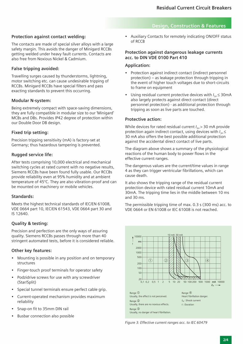
The diagram above shows a summary of the physiologicalreactions of the human body to power flows in theeffective current ranges.
The dangerous values are the current/time values in range4 as they can trigger ventricular fibrillations, which cancause death.
It also shows the tripping range of the residual currentprotection device with rated residual current 10mA and30mA. The tripping time lies in the middle between 10 msand 30 ms.
The permissible tripping time of max. 0.3 s (300 ms) acc. toVDE 0664 or EN 61008 or IEC 61008 is not reached.
Range Usually, the effect is not perceived.
Range Usually, there are no noxious effects.
Range Usually, no danger of heart fibrillation.
Figure 3: Effective current ranges acc. to IEC 60479
Range Heart fibrillation danger.
IM : Shock current
t : Duration
Residual Current Circuit Breakers
Design, Construction & Features
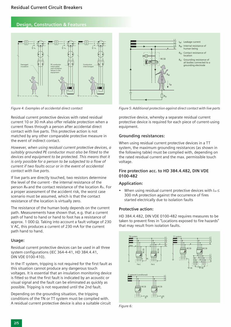
Residual current protective devices with rated residualcurrent 10 or 30 mA also offer reliable protection when acurrent flows through a person after accidental directcontact with live parts. This protective action is notmatched by any other comparable protective measure inthe event of indirect contact.
However, when using residual current protective devices, asuitably grounded PE conductor must also be fitted to thedevices and equipment to be protected. This means that itis only possible for a person to be subjected to a flow ofcurrent if two faults occur or in the event of accidentalcontact with live parts.
If live parts are directly touched, two resistors determinethe level of the current - the internal resistance of theperson RM and the contact resistance of the location RSt. Fora proper assessment of the accident risk, the worst casescenario must be assumed, which is that the contactresistance of the location is virtually zero.
The resistance of the human body depends on the currentpath. Measurements have shown that, e.g. that a currentpath of hand to hand or hand to foot has a resistance ofapprox. 1 000 Ω. Taking into account a fault voltage of 230V AC, this produces a current of 230 mA for the currentpath hand to hand.
Usage:
Residual current protective devices can be used in all threesystem configurations (IEC 364-4-41, HD 384.4.41,DIN VDE 0100-410).
In the IT system, tripping is not required for the first fault asthis situation cannot produce any dangerous touchvoltages. It is essential that an insulation monitoring deviceis fitted so that the first fault is indicated by an acoustic orvisual signal and the fault can be eliminated as quickly aspossible. Tripping is not requested until the 2nd fault.
Depending on the grounding situation, the trippingconditions of the TN or TT system must be complied with.A residual current protective device is also a suitable circuit
Figure 5: Additional protection against direct contact with live parts
protective device, whereby a separate residual currentprotective device is required for each piece of current-usingequipment.
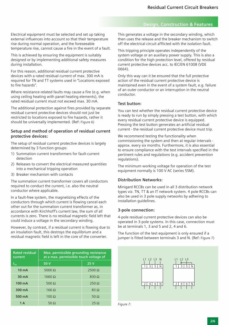
Grounding resistances:
When using residual current protective devices in a TTsystem, the maximum grounding resistances (as shown inthe following table) must be complied with, depending onthe rated residual current and the max. permissible touchvoltage.
Fire protection acc. to HD 384.4.482, DIN VDE0100-482
Application:
• When using residual current protective devices with IΔn ≤300 mA protection against the occurrence of firesstarted electrically due to isolation faults
Protective action:
HD 384.4.482, DIN VDE 0100-482 requires measures to betaken to prevent fires in “Locations exposed to fire hazards”that may result from isolation faults.
2/5
Figure 4: Examples of accidental direct contact
Figure 6:
Residual Current Circuit Breakers
Design, Construction & Features
Electrical equipment must be selected and set up takingexternal influences into account so that their temperaturerise during normal operation, and the foreseeabletemperature rise, cannot cause a fire in the event of a fault.
This is achieved by ensuring the equipment is suitablydesigned or by implementing additional safety measuresduring installation.
For this reason, additional residual current protectivedevices with a rated residual current of max. 300 mA isrequired for TN and TT systems used in “Locations exposedto fire hazards”.
Where resistance-related faults may cause a fire (e.g. whenusing ceiling heating with panel heating elements), therated residual current must not exceed max. 30 mA.
The additional protection against fires provided by separateresidual current protective devices should not just berestricted to locations exposed to fire hazards, rather itshould be universally implemented. (Ref: Figure 6)
Setup and method of operation of residual currentprotective devices:
The setup of residual current protective devices is largelydetermined by 3 function groups:
1) Summation current transformers for fault-currentdetection
2) Releases to convert the electrical measured quantitiesinto a mechanical tripping operation
3) Breaker mechanism with contacts
The summation current transformer covers all conductorsrequired to conduct the current, i.e. also the neutralconductor where applicable.
In a fault-free system, the magnetizing effects of theconductors through which current is flowing cancel eachother out for the summation current transformer as, inaccordance with Kirchhoff’s current law, the sum of allcurrents is zero. There is no residual magnetic field left thatcould induce a voltage in the secondary winding.
However, by contrast, if a residual current is flowing due toan insulation fault, this destroys the equilibrium and aresidual magnetic field is left in the core of the converter.
Rated residual Max. permissible grounding resistancecurrent at a max. permissible touch voltage of
IDn 50 V 25 V
10 mA 5000 Ω 2500 Ω
30 mA 1660 Ω 830 Ω
100 mA 500 Ω 250 Ω
300 mA 166 Ω 83 Ω
500 mA 100 Ω 50 Ω
1 A 50 Ω 25 Ω
This generates a voltage in the secondary winding, whichthen uses the release and the breaker mechanism to switchoff the electrical circuit afflicted with the isolation fault.
This tripping principle operates independently of thesystem voltage or an auxiliary power supply. This is also acondition for the high protection level, offered by residualcurrent protective devices acc. to IEC/EN 61008 (VDE0664).
Only this way can it be ensured that the full protectiveaction of the residual current protective device ismaintained even in the event of a system fault, e.g. failureof an outer conductor or an interruption in the neutralconductor.
Test button:
You can test whether the residual current protective deviceis ready to run by simply pressing a test button, with whichevery residual current protective device is equipped.Pressing the test button generates an artificial residualcurrent - the residual current protective device must trip.
We recommend testing the functionality whencommissioning the system and then at regular intervals -approx. every six months. Furthermore, it is also essentialto ensure compliance with the test intervals specified in thepertinent rules and regulations (e.g. accident preventionregulations).
The minimum working voltage for operation of the testequipment normally is 100 V AC (series 5SM).
Distribution Networks:
Minigard RCCBs can be used in all 3 distribution networktypes viz. TN, TT & an IT network system. 4 pole RCCBs canalso be used in 3 pole supply networks by adhering toinstallation guidelines.
3-pole connection:
4-pole residual current protective devices can also beoperated in 3-pole systems. In this case, connection mustbe at terminals 1, 3 and 5 and 2, 4 and 6.
The function of the test equipment is only ensured if ajumper is fitted between terminals 3 and N. (Ref: Figure 7)
2/6
Figure 7:
2/7
Residual Current Circuit Breakers
Design, Construction & Features
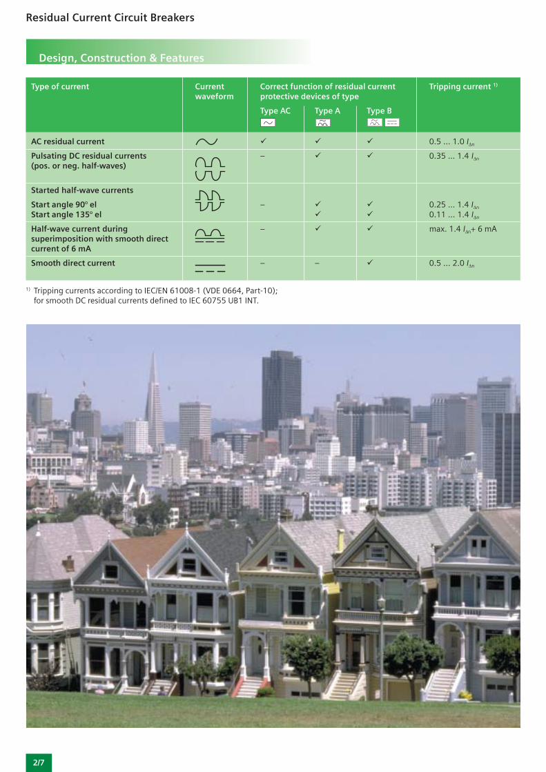
Type of current Current Correct function of residual current Tripping current 1)
waveform protective devices of type
Type AC Type A Type B
AC residual current 0.5 ... 1.0 IΔn
Pulsating DC residual currents – 0.35 ... 1.4 IΔn
(pos. or neg. half-waves)
Started half-wave currents
Start angle 90° el – 0.25 ... 1.4 IΔn
Start angle 135° el 0.11 ... 1.4 IΔn
Half-wave current during – max. 1.4 IΔn+ 6 mAsuperimposition with smooth directcurrent of 6 mA
Smooth direct current – – 0.5 ... 2.0 IΔn
1) Tripping currents according to IEC/EN 61008-1 (VDE 0664, Part-10);for smooth DC residual currents defined to IEC 60755 UB1 INT.
2/8
Residual Current Circuit Breakers
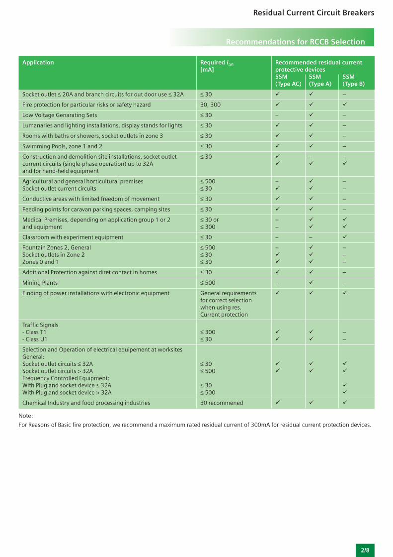
Application Required IΔn Recommended residual current[mA] protective devices
5SM 5SM 5SM(Type AC) (Type A) (Type B)
Socket outlet ≤ 20A and branch circuits for out door use ≤ 32A ≤ 30 –
Fire protection for particular risks or safety hazard 30, 300
Low Voltage Genarating Sets ≤ 30 – –
Lumanaries and lighting installations, display stands for lights ≤ 30 –
Rooms with baths or showers, socket outlets in zone 3 ≤ 30 –
Swimming Pools, zone 1 and 2 ≤ 30 –
Construction and demolition site installations, socket outlet ≤ 30 – –current circuits (single-phase operation) up to 32Aand for hand-held equipment
Agricultural and general horticultural premises ≤ 500 – –Socket outlet current circuits ≤ 30 –
Conductive areas with limited freedom of movement ≤ 30 –
Feeding points for caravan parking spaces, camping sites ≤ 30 –
Medical Premises, depending on application group 1 or 2 ≤ 30 or –and equipment ≤ 300 –
Classroom with experiment equipment ≤ 30 – –
Fountain Zones 2, General ≤ 500 – –Socket outlets in Zone 2 ≤ 30 –Zones 0 and 1 ≤ 30 –
Additional Protection against diret contact in homes ≤ 30 –
Mining Plants ≤ 500 – –
Finding of power installations with electronic equipment General requirementsfor correct selectionwhen using res.Current protection
Traffic Signals- Class T1 ≤ 300 –- Class U1 ≤ 30 –
Selection and Operation of electrical equipement at worksitesGeneral:Socket outlet circuits ≤ 32A ≤ 30Socket outlet circuits > 32A ≤ 500Frequency Controlled Equipment:With Plug and socket device ≤ 32A ≤ 30With Plug and socket device > 32A ≤ 500
Chemical Industry and food processing industries 30 recommened
Note:
For Reasons of Basic fire protection, we recommend a maximum rated residual current of 300mA for residual current protection devices.
Recommendations for RCCB Selection
2/9
Residual Current Circuit Breakers
Technical Specifications
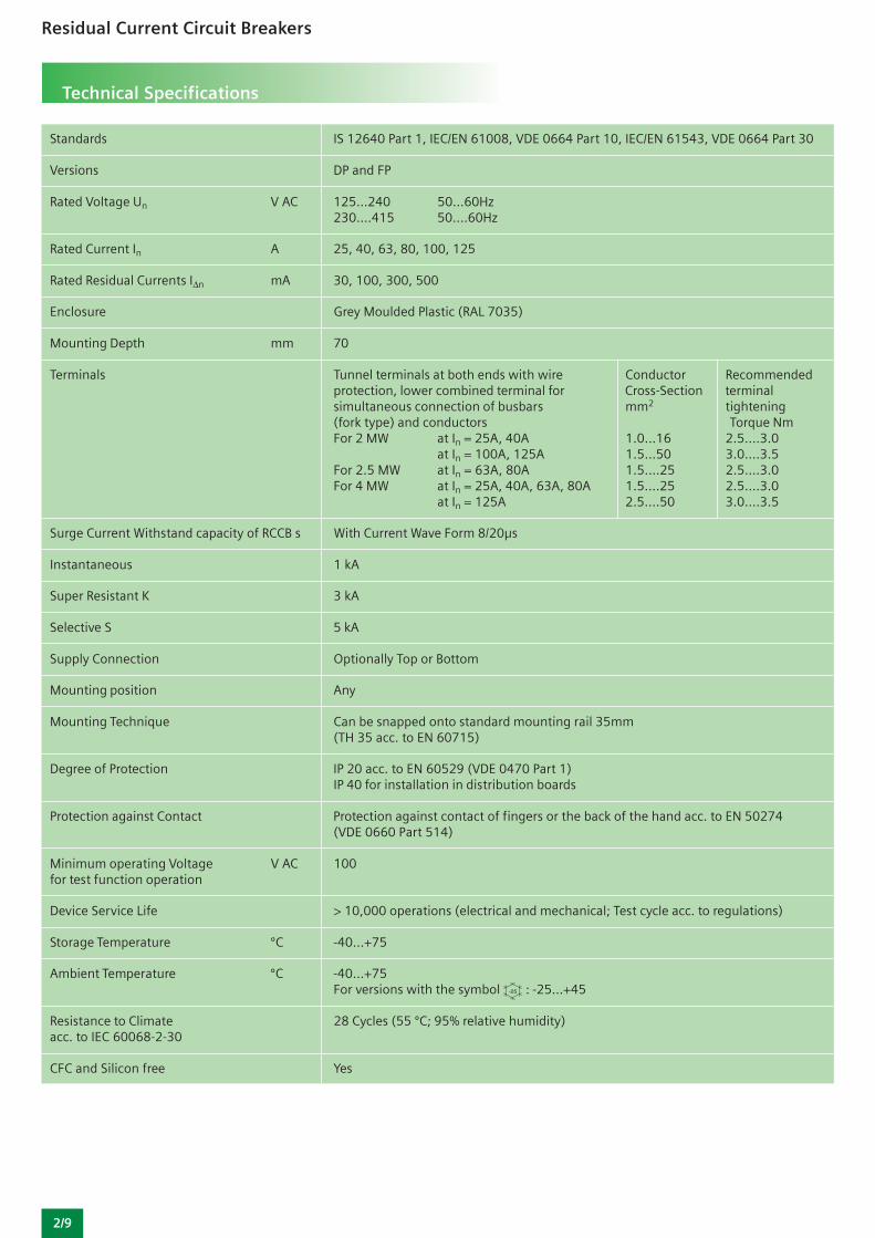
Standards IS 12640 Part 1, IEC/EN 61008, VDE 0664 Part 10, IEC/EN 61543, VDE 0664 Part 30
Versions DP and FP
Rated Voltage Un V AC 125…240 50…60Hz230….415 50….60Hz
Rated Current In A 25, 40, 63, 80, 100, 125
Rated Residual Currents IΔn mA 30, 100, 300, 500
Enclosure Grey Moulded Plastic (RAL 7035)
Mounting Depth mm 70
Terminals Tunnel terminals at both ends with wire Conductor Recommendedprotection, lower combined terminal for Cross-Section terminalsimultaneous connection of busbars mm2 tightening(fork type) and conductors Torque NmFor 2 MW at In = 25A, 40A 1.0…16 2.5….3.0
at In = 100A, 125A 1.5…50 3.0….3.5For 2.5 MW at In = 63A, 80A 1.5….25 2.5….3.0For 4 MW at In = 25A, 40A, 63A, 80A 1.5….25 2.5….3.0
at In = 125A 2.5….50 3.0….3.5
Surge Current Withstand capacity of RCCB s With Current Wave Form 8/20μs
Instantaneous 1 kA
Super Resistant K 3 kA
Selective S 5 kA
Supply Connection Optionally Top or Bottom
Mounting position Any
Mounting Technique Can be snapped onto standard mounting rail 35mm(TH 35 acc. to EN 60715)
Degree of Protection IP 20 acc. to EN 60529 (VDE 0470 Part 1)IP 40 for installation in distribution boards
Protection against Contact Protection against contact of fingers or the back of the hand acc. to EN 50274(VDE 0660 Part 514)
Minimum operating Voltage V AC 100for test function operation
Device Service Life > 10,000 operations (electrical and mechanical; Test cycle acc. to regulations)
Storage Temperature ºC -40…+75
Ambient Temperature ºC -40…+75For versions with the symbol : -25…+45
Resistance to Climate 28 Cycles (55 ºC; 95% relative humidity)acc. to IEC 60068-2-30
CFC and Silicon free Yes
Residual Current Circuit Breakers
Product Overview
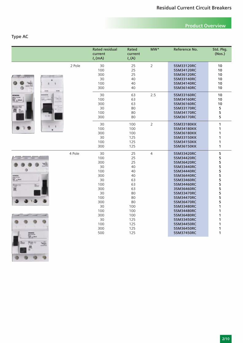
Type AC
Rated residual Rated MW* Reference No. Std. Pkg.current current (Nos.)In (mA) In (A)
2 Pole 30 25 2 5SM33120RC 10100 25 5SM34120RC 10300 25 5SM36120RC 10
30 40 5SM33140RC 10100 40 5SM34140RC 10300 40 5SM36140RC 10
30 63 2.5 5SM33160RC 10100 63 5SM34160RC 10300 63 5SM36160RC 10
30 80 5SM33170RC 5100 80 5SM34170RC 5300 80 5SM36170RC 5
30 100 2 5SM33180KK 1100 100 5SM34180KK 1300 100 5SM36180KK 1
30 125 5SM33150KK 1100 125 5SM34150KK 1300 125 5SM36150KK 1
4 Pole 30 25 4 5SM33420RC 5100 25 5SM34420RC 5300 25 5SM36420RC 5
30 40 5SM33440RC 5100 40 5SM34440RC 5300 40 5SM36440RC 5
30 63 5SM33460RC 5100 63 5SM34460RC 5300 63 3SM36460RC 5
30 80 5SM33470RC 5100 80 5SM34470RC 5300 80 5SM36470RC 5
30 100 5SM33480RC 1100 100 5SM34480RC 1300 100 5SM36480RC 1
30 125 5SM33450RC 1100 125 5SM34450RC 1300 125 5SM36450RC 1500 125 5SM37450RC 1
2/10
2/11
Residual Current Circuit Breakers
Product Overview
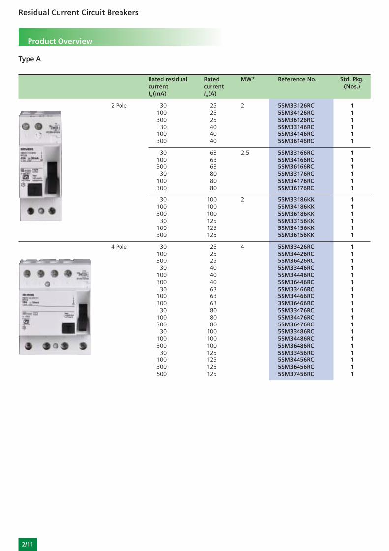
Type A
Rated residual Rated MW* Reference No. Std. Pkg.current current (Nos.)In (mA) In (A)
2 Pole 30 25 2 5SM33126RC 1100 25 5SM34126RC 1300 25 5SM36126RC 1
30 40 5SM33146RC 1100 40 5SM34146RC 1300 40 5SM36146RC 1
30 63 2.5 5SM33166RC 1100 63 5SM34166RC 1300 63 5SM36166RC 1
30 80 5SM33176RC 1100 80 5SM34176RC 1300 80 5SM36176RC 1
30 100 2 5SM33186KK 1100 100 5SM34186KK 1300 100 5SM36186KK 1
30 125 5SM33156KK 1100 125 5SM34156KK 1300 125 5SM36156KK 1
4 Pole 30 25 4 5SM33426RC 1100 25 5SM34426RC 1300 25 5SM36426RC 1
30 40 5SM33446RC 1100 40 5SM34446RC 1300 40 5SM36446RC 1
30 63 5SM33466RC 1100 63 5SM34466RC 1300 63 3SM36466RC 1
30 80 5SM33476RC 1100 80 5SM34476RC 1300 80 5SM36476RC 1
30 100 5SM33486RC 1100 100 5SM34486RC 1300 100 5SM36486RC 1
30 125 5SM33456RC 1100 125 5SM34456RC 1300 125 5SM36456RC 1500 125 5SM37456RC 1
Residual Current Circuit Breakers
Product Overview
2/12
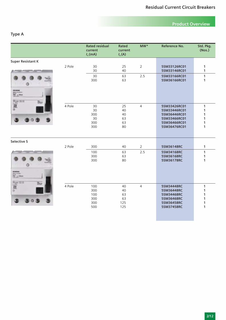
Type A
Rated residual Rated MW* Reference No. Std. Pkg.current current (Nos.)In (mA) In (A)
Super Resistant K
2 Pole 30 25 2 5SM33126RC01 130 40 5SM33146RC01 1
30 63 2.5 5SM33166RC01 1300 63 5SM36166RC01 1
4 Pole 30 25 4 5SM33426RC01 130 40 5SM33446RC01 1
300 40 5SM36446RC01 130 63 5SM33466RC01 1
300 63 5SM36466RC01 1300 80 5SM36476RC01 1
Selective S
2 Pole 300 40 2 5SM36148RC 1
100 63 2.5 5SM34168RC 1300 63 5SM36168RC 1300 80 5SM36178RC 1
4 Pole 100 40 4 5SM34448RC 1300 40 5SM36448RC 1100 63 5SM34468RC 1300 63 5SM36468RC 1300 125 5SM36458RC 1500 125 5SM37458RC 1
2/13
Residual Current Circuit Breakers
Product Overview
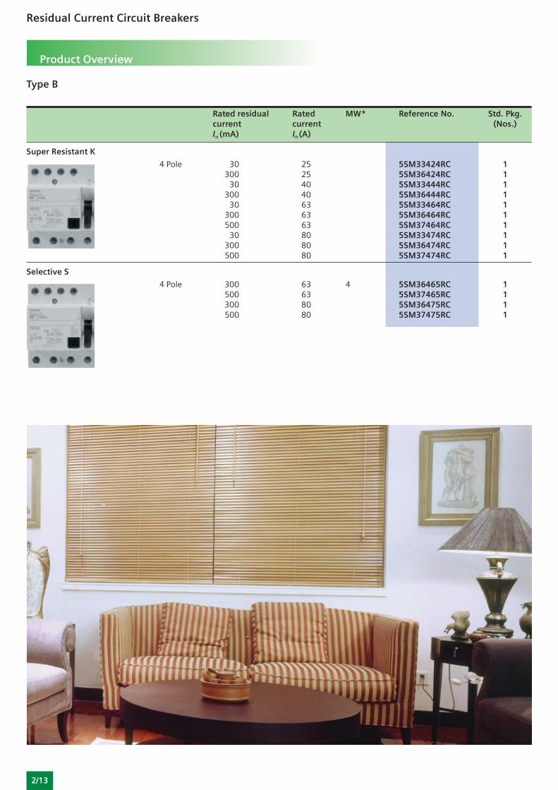
Type B
Rated residual Rated MW* Reference No. Std. Pkg.current current (Nos.)In (mA) In (A)
Super Resistant K
4 Pole 30 25 5SM33424RC 1300 25 5SM36424RC 1
30 40 5SM33444RC 1300 40 5SM36444RC 1
30 63 5SM33464RC 1300 63 5SM36464RC 1500 63 5SM37464RC 1
30 80 5SM33474RC 1300 80 5SM36474RC 1500 80 5SM37474RC 1
Selective S
4 Pole 300 63 4 5SM36465RC 1500 63 5SM37465RC 1300 80 5SM36475RC 1500 80 5SM37475RC 1


![MDC/BD A[IR] and A[S] type residual current circuit ... · "mdc" residual current circuit breakers with overcurrent protection (en 61009-1) iΔn = 30ma iΔn = 300ma icn [a] curve](https://img.pdfslide.us/doc/110x75/5f074eb97e708231d41c56b2/mdcbd-air-and-as-type-residual-current-circuit-mdc-residual.jpg)