Embed Size (px)
Citation preview

DOE Fundamentals
MECHANICAL SCIENCE
Module 5
Miscellaneous Mechanical Components
Mechanical Science Miscellaneous Mechanical Components
MS-05-i
TABLE OF CONTENTS
TABLE OF CONTENTS ............................................................................................................... i
LIST OF FIGURES .................................................................................................................... iv
LIST OF TABLES ........................................................................................................................ v
REFERENCES .......................................................................................................................... vi
OBJECTIVES ........................................................................................................................... vii
AIR COMPRESSORS ................................................................................................................ 1
Introduction ............................................................................................................................ 1
Reciprocating Compressors ................................................................................................... 1
Rotary Compressors ............................................................................................................... 3
Centrifugal Compressors ........................................................................................................ 5
Compressor Coolers ............................................................................................................... 6
Hazards of Compressed Air .................................................................................................... 7
Summary ................................................................................................................................ 8
HYDRAULICS ...........................................................................................................................10
Introduction ...........................................................................................................................10
Pressure and Force ...............................................................................................................10
Hydraulic Operation ...............................................................................................................11
Hazards .................................................................................................................................12
Summary ...............................................................................................................................13
BOILERS ..................................................................................................................................14
Introduction ...........................................................................................................................14
Boilers ...................................................................................................................................14
Fuel Boiler Components ........................................................................................................15
Summary ...............................................................................................................................17
COOLING TOWERS .................................................................................................................18
Purpose .................................................................................................................................18
Induced Draft Cooling Towers ...............................................................................................19
Forced Draft Cooling Towers .................................................................................................21
Natural Convection Cooling Towers ......................................................................................21
Summary ...............................................................................................................................22

Mechanical Science Miscellaneous Mechanical Components
MS-05-ii
DEMINERALIZERS ..................................................................................................................23
Purpose of Demineralizers ....................................................................................................23
Demineralizers ......................................................................................................................23
Single-Bed Demineralizers ....................................................................................................23
Single-Bed Regeneration.......................................................................................................24
Mixed-Bed Demineralizer ......................................................................................................25
Mixed-Bed Regeneration .......................................................................................................25
External Regeneration ...........................................................................................................27
Summary ...............................................................................................................................28
PRESSURIZERS ......................................................................................................................29
Introduction ...........................................................................................................................29
General Description ...............................................................................................................30
Dynamic Pressurizers ............................................................................................................30
Construction ..........................................................................................................................30
Operation ..............................................................................................................................31
Summary ...............................................................................................................................33
STEAM TRAPS .........................................................................................................................34
General Operation .................................................................................................................34
Ball Float Steam Trap ............................................................................................................34
Bucket Steam Trap ................................................................................................................34
Thermostatic Steam Traps ....................................................................................................35
Bellows-Type Steam Trap .....................................................................................................35
Impulse Steam Trap ..............................................................................................................36
Orifice-Type Steam Trap .......................................................................................................37
Summary ...............................................................................................................................38
FILTERS AND STRAINERS .....................................................................................................39
Introduction ...........................................................................................................................39
Cartridge Filters .....................................................................................................................39
Precoat Filters .......................................................................................................................41
Backwashing Precoat Filters .................................................................................................42
Deep-Bed Filters ...................................................................................................................42
Metal-Edged Filters ...............................................................................................................43
Strainers ................................................................................................................................44

Mechanical Science Miscellaneous Mechanical Components
MS-05-iii
Backwashing .........................................................................................................................45
Summary ...............................................................................................................................46

Mechanical Science Miscellaneous Mechanical Components
MS-05-iv
LIST OF FIGURES
Figure 1 Reciprocating Air Compressor ..................................................................................... 2
Figure 2 Single-Acting Air Compressor Cylinder ....................................................................... 3
Figure 3 Rotary Slide Vane Air Compressor .............................................................................. 4
Figure 4 Rotary Lobe Air Compressor ....................................................................................... 5
Figure 5 Rotary Liquid Seal Ring Air Compressor ..................................................................... 5
Figure 6 Simplified Centrifugal Pump ........................................................................................ 6
Figure 7 Compressor Air Cooler ................................................................................................ 7
Figure 8 Basic Hydraulic System ............................................................................................. 12
Figure 9 Typical Fuel Boiler ..................................................................................................... 15
Figure 10 Cooling System Containing Cooling Tower ............................................................. 18
Figure 11 Induced Draft Cooling Tower ................................................................................... 19
Figure 12 Natural Convection Cooling Tower .......................................................................... 22
Figure 13 Single-Bed Demineralizer ........................................................................................ 25
Figure 14 Regeneration of a Mixed-Bed Demineralizer ........................................................... 27
Figure 15 A Basic Pressurizer ................................................................................................. 32
Figure 16 Ball Float Steam Trap .............................................................................................. 35
Figure 17 Bucket Steam Trap ................................................................................................. 36
Figure 18 Bellows-Type Steam Trap ....................................................................................... 36
Figure 19 Impulse Steam Trap ................................................................................................ 37
Figure 20 Typical Multiline-Cartridge Filter .............................................................................. 41
Figure 21 Cartridge Filter ........................................................................................................ 41
Figure 22 Deep-Bed Filter ....................................................................................................... 44
Figure 23 Y-strainer ................................................................................................................ 45
Figure 24 Common Strainers .................................................................................................. 46

Mechanical Science Miscellaneous Mechanical Components
MS-05-v
LIST OF TABLES
NONE
Mechanical Science Miscellaneous Mechanical Components
MS-05-vi
REFERENCES
Babcock & Wilcox, Steam, Its Generations and Use, Babcock & Wilcox Co, 41st Edition.
Benson & Whitehouse, Internal Combustion Engines, Pergamon.
Bureau of Naval Personnel, Principles of Naval Engineering, Training Publication
Division, Naval Personnel Program Support Activity, Washington D.C., 1970.
Cheremisinoff, N. P., Fluid Flow, Pumps, Pipes and Channels, Ann Arbor Science.
E.E.U.A., Steam Trapping and Condensate Removal, Constable & Company.
Heat Transfer, Thermodynamics and Fluid Flow Fundamentals, Columbia, MD, General
Physics Corporation.
General Physics, Volume IV, Chemistry, Health Physics and Nuclear Instrumentation,
General Physics Corporation.
Marley, Cooling Tower Fundamentals and Applications, The Marley Company.
Scheel, Gas and Air Compression Machinery, McGraw/Hill.
Stewart, Harry L., Pneumatics & Hydraulics, Theodore Audel & Company.

Mechanical Science Miscellaneous Mechanical Components
MS-05-vii
OBJECTIVES
TERMINAL OBJECTIVE
1.0 Without references, DESCRIBE the purpose, construction, and operation of
miscellaneous mechanical components.
ENABLING OBJECTIVES
1.1 STATE the three common types of air compressors.
1.2 DESCRIBE the basic operation of the following types of air compressors:
a. Reciprocating
b. Centrifugal
c. Rotary
1.3 STATE the reason for using cooling systems in air compressors.
1.4 STATE three hazards associated with pressurized air systems.
1.5 Given the appropriate information, CALCULATE the pressure or force achieved in a
hydraulic piston.
1.6 DESCRIBE the basic operation of a hydraulic system.
1.7 DESCRIBE the basic operation of a boiler.
1.8 IDENTIFY the following components of a typical boiler:
a. Steam drum d. Downcomer
b. Distribution header(s) e. Risers
c. Combustion chamber
1.9 STATE the purpose of cooling towers.
1.10 DESCRIBE the operation of the following types of cooling towers.
a. Forced draft
b. Natural convection
1.11 STATE the purpose of a demineralizer.
1.12 STATE the four purposes of a pressurizer.
1.13 DEFINE the following terms attributable to a dynamic pressurizer:
a. Spray nozzle c. Outsurge
b. Insurge d. Surge volume
1.14 STATE the purpose and general operation of a steam trap.

Mechanical Science Miscellaneous Mechanical Components
MS-05-viii
1.15 IDENTIFY the following types of steam traps:
a. Ball float steam trap c. Bucket steam trap
b. Bellow steam trap d. Impulse steam trap
1.16 DESCRIBE each of the following types of strainers and filters, including an example of
typical use.
a. Cartridge filters d. Bucket strainer
b. Precoated filters e. Duplex strainer
c. Deep-bed filters
1.17 EXPLAIN the application and operation of a strainer or filter backwash.

Mechanical Science Miscellaneous Mechanical Components
MS-05-1
AIR COMPRESSORS
The purpose of an air compressor is to provide a continuous supply of
pressurized air. This chapter will describe the various types of compressors and
their basic operation.
EO 1.1 STATE the three common types of air compressors.
EO 1.2 DESCRIBE the basic operation of the following types of air compressors:
a. Reciprocating
b. Centrifugal
c. Rotary
EO 1.3 STATE the reason for using cooling systems in air compressors.
EO 1.4 STATE three hazards associated with pressurized air systems.
Introduction
Air compressors of various designs are used widely throughout DOE facilities in numerous
applications. Compressed air has numerous uses throughout a facility including the operation of
equipment and portable tools. Three types of designs include reciprocating, rotary, and
centrifugal air compressors.
Reciprocating Compressors
The reciprocating air compressor, illustrated in Figure 1, is the most common design employed
today.
The reciprocating compressor normally consists of the following elements.
a. The compressing element, consisting of air cylinders, heads and pistons, and air
inlet and discharge valves.
b. A system of connecting rods, piston rods, crossheads, and a crankshaft and
flywheel for transmitting the power developed by the driving unit to the air
cylinder piston.
c. A self-contained lubricating system for bearings, gears, and cylinder walls,
including a reservoir or sump for the lubricating oil, and a pump, or other means
of delivering oil to the various parts. On some compressors a separate force-fed
lubricator is installed to supply oil to the compressor cylinders.
d. A regulation or control system designed to maintain the pressure in the discharge
line and air receiver (storage tank) within a predetermined range of pressure.

Mechanical Science Miscellaneous Mechanical Components
MS-05-2
e. An unloading system, which operates in conjunction with the regulator, to reduce
or eliminate the load put on the prime mover when starting the unit.
Figure 1 Reciprocating Air Compressor
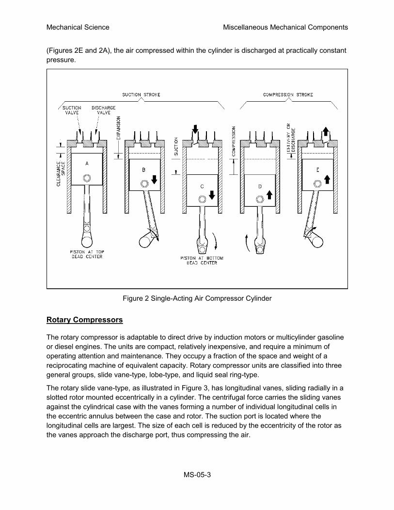
A section of a typical reciprocating single-stage, single-acting compressor cylinder is shown in
Figure 2. Inlet and discharge valves are located in the clearance space and connected through
ports in the cylinder head to the inlet and discharge connections.
During the suction stroke the compressor piston starts its downward stroke and the air under
pressure in the clearance space rapidly expands until the pressure falls below that on the
opposite side of the inlet valve (Figures 2B and 2C). This difference in pressure causes the inlet
valve to open into the cylinder until the piston reaches the bottom of its stroke (Figure 2C).
During the compression stroke the piston starts upward, compression begins, and at point D
has reached the same pressure as the compressor intake. The spring-loaded inlet valve then
closes. As the piston continues upward, air is compressed until the pressure in the cylinder
becomes great enough to open the discharge valve against the pressure of the valve springs
and the pressure of the discharge line (Figure 2E). From this point, to the end of the stroke
Mechanical Science Miscellaneous Mechanical Components
MS-05-3
(Figures 2E and 2A), the air compressed within the cylinder is discharged at practically constant
pressure.
Figure 2 Single-Acting Air Compressor Cylinder
Rotary Compressors
The rotary compressor is adaptable to direct drive by induction motors or multicylinder gasoline
or diesel engines. The units are compact, relatively inexpensive, and require a minimum of
operating attention and maintenance. They occupy a fraction of the space and weight of a
reciprocating machine of equivalent capacity. Rotary compressor units are classified into three
general groups, slide vane-type, lobe-type, and liquid seal ring-type.
The rotary slide vane-type, as illustrated in Figure 3, has longitudinal vanes, sliding radially in a
slotted rotor mounted eccentrically in a cylinder. The centrifugal force carries the sliding vanes
against the cylindrical case with the vanes forming a number of individual longitudinal cells in
the eccentric annulus between the case and rotor. The suction port is located where the
longitudinal cells are largest. The size of each cell is reduced by the eccentricity of the rotor as
the vanes approach the discharge port, thus compressing the air.

Mechanical Science Miscellaneous Mechanical Components
MS-05-4
Figure 3 Rotary Slide Vane Air Compressor
The rotary lobe-type, illustrated in Figure
4, features two mating lobe-type rotors
mounted in a case. The lobes are gear
driven at close clearance, but without
metal-to-metal contact. The suction to the
unit is located where the cavity made by
the lobes is largest. As the lobes rotate,
the cavity size is reduced, causing
compression of the vapor within. The
compression continues until the
discharge port is reached, at which point
the vapor exits the compressor at a
higher pressure.
The rotary liquid seal ring-type, illustrated
in Figure 5, features a forward inclined,
open impeller, in an oblong cavity filled
with liquid. As the impeller rotates, the centrifugal force causes the seal liquid to collect at the
outer edge of the oblong cavity. Due to the oblong configuration of the compressor case, large
longitudinal cells are created and reduced to smaller ones. The suction port is positioned where
the longitudinal cells are the largest, and for the discharge port, where they are smallest, thus
causing the vapor within the cell to compress as the rotor rotates. The rotary liquid seal
compressor is frequently used in specialized applications for the compression of extremely
corrosive and exothermic gasses and is commonly used in commercial nuclear plants as a
means of establishing initial condenser vacuum.
Figure 4 Rotary Lobe Air Compressor
Mechanical Science Miscellaneous Mechanical Components
MS-05-5
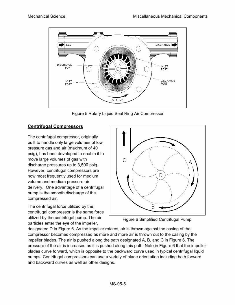
Figure 5 Rotary Liquid Seal Ring Air Compressor
Centrifugal Compressors
The centrifugal compressor, originally
built to handle only large volumes of low
pressure gas and air (maximum of 40
psig), has been developed to enable it to
move large volumes of gas with
discharge pressures up to 3,500 psig.
However, centrifugal compressors are
now most frequently used for medium
volume and medium pressure air
delivery. One advantage of a centrifugal
pump is the smooth discharge of the
compressed air.
The centrifugal force utilized by the
centrifugal compressor is the same force
utilized by the centrifugal pump. The air
particles enter the eye of the impeller,
designated D in Figure 6. As the impeller rotates, air is thrown against the casing of the
compressor becomes compressed as more and more air is thrown out to the casing by the
impeller blades. The air is pushed along the path designated A, B, and C in Figure 6. The
pressure of the air is increased as it is pushed along this path. Note in Figure 6 that the impeller
blades curve forward, which is opposite to the backward curve used in typical centrifugal liquid
pumps. Centrifugal compressors can use a variety of blade orientation including both forward
and backward curves as well as other designs.
Figure 6 Simplified Centrifugal Pump

Mechanical Science Miscellaneous Mechanical Components
MS-05-6
There may be several stages to a centrifugal air compressor, as in the centrifugal pump, and the
result would be the same; a higher pressure would be produced. The air compressor is used to
create compressed or high pressure air for a variety of uses. Some of its uses are pneumatic
control devices, pneumatic sensors, pneumatic valve operators, pneumatic motors, and starting
air for diesel engines.
Compressor Coolers
The amount of moisture that air can hold is inversely proportional to the pressure of the air. As
the pressure of the air increases, the amount of moisture that air can hold decreases. The
amount of moisture that air can hold is also proportional to the temperature of the air. As the
temperature of the air increases, the amount of moisture it can hold increases. However, the
pressure change of compressed air is larger than the temperature change of the compressed
air. This causes the moisture in the air to condense. Moisture in compressed air systems can
cause serious damage. The condensed moisture can cause corrosion, water hammers, and
freeze damage; therefore, it is important to avoid moisture in compressed air systems. Coolers
are used to minimize the problems caused by heat and moisture in compressed air systems.
Figure 7 Compressor Air Cooler
Coolers used on the discharge of a compressor are called aftercoolers. Their purpose is to
remove the heat generated during the compression of the air. The decrease in temperature
promotes the condensing of any moisture present in the compressed air. This moisture is
collected in condensate traps that are either automatically or manually drained.
If the compressor is multi-staged, there may be an intercooler, which is usually located after the
first stage discharge and before the second stage suction. The principle of the intercooler is the
same as that of the aftercoolers. The result is drier, cooler, compressed air. The structure of a
particular cooler depends on the pressure and volume of the air it cools. Figure 7 illustrates a
typical compressor air cooler. Air coolers are used because drier compressed air helps prevent
corrosion and cooler compressed air allows more air to be compressed for a set volume.

Mechanical Science Miscellaneous Mechanical Components
MS-05-7
Hazards of Compressed Air
People often lack respect for the power in compressed air because air is so common and is
often viewed as harmless. At sufficient pressures, compressed air can cause serious damage if
handled incorrectly. To minimize the hazards of working with compressed air, all safety
precautions should be followed closely.
Small leaks or breaks in the compressed air system can cause minute particles to be blown at
extremely high speeds. Always wear safety glasses when working in the vicinity of any
compressed air system. Safety goggles are recommended if contact lenses are worn.
Compressors can make an exceptional amount of noise while running. The noise of the
compressor, in addition to the drain valves lifting, creates enough noise to require hearing
protection. The area around compressors should normally be posted as a hearing protection
zone.
Pressurized air can do the same type of damage as pressurized water. Treat all operations on
compressed air systems with the same care taken on liquid systems. Closed valves should be
slowly cracked open and both sides should be allowed to equalize prior to opening the valve
further. Systems being opened for maintenance should always be depressurized before work
begins.
Great care should be taken to keep contaminants from entering air systems. This is especially
true for oil. Oil introduced in an air compressor can be compressed to the point where
detonation takes place in a similar manner as that which occurs in a diesel engine. This
detonation can cause equipment damage and personnel injury.

Mechanical Science Miscellaneous Mechanical Components
MS-05-8
Summary
The important information in this chapter is summarized below.
Air Compressors Summary
The three common types of air compressors are reciprocating, rotary, and centrifugal.
The single-stage reciprocating compressor has a piston that moves downward during
the suction stroke, expanding the air in the cylinder. The expanding air causes pressure
in the cylinder to drop. When the pressure falls below the pressure on the other side of
the inlet valve, the valve opens and allows air in until the pressure equalizes across the
inlet valve. The piston bottoms out and then begins a compression stroke. The upward
movement of the piston compresses the air in the cylinder, causing the pressure across
the inlet valve to equalize and the inlet valve to reseat. The piston continues to
compress air during the remainder of the upward stroke until the cylinder pressure is
great enough to open the discharge valve against the valve spring pressure. Once the
discharge valve is open, the air compressed in the cylinder is discharged until the
piston completes the stroke.
The centrifugal force utilized by the centrifugal compressors is the same force utilized
by the centrifugal pumps. The air particles enter the eye of the impeller. As the impeller
rotates, air is thrown against the casing of the compressor. The air becomes
compressed as more and more air is thrown out to the casing by the impeller blades.
The air is pushed along the path on the inner wall of the casing. The pressure of the air
is increased as it is pushed along this path. There could be several stages to a
centrifugal air compressor just as in the centrifugal pump, resulting in higher pressure.
Rotary compressors are driven by a direct drive that rotates a mechanism (impellers,
vanes, or lobes) that compresses the air being pumped. The actual compression of the
air takes place due either to centrifugal forces or a diminishing air space as the
impellers rotate.
Cooling systems are required in compressed air systems to remove any heat added by
the compression. The advantages to cooling the compressed air are that cool air takes
less space and holds less moisture. This reduces corrosion and allows more air to be
compressed into a given volume.
Mechanical Science Miscellaneous Mechanical Components
MS-05-9
Hazards associated with compressed air are similar to hazards of any high pressure
system. Three general hazards include the following.
o Small leaks or breaks can cause minute particles to be blown at speeds high
enough to cause damage. Goggles or safety glasses should be worn when working
around compressed gas.
o The compressors, especially larger ones, can be quite noisy when running. The
cycling of automatic drain valves contributes noise as well. Hearing protection
should be worn around compressors.
o Pressure swings may cause system damage. Closed valves in a compressed air
system should be slowly cracked open and the pressure should be allowed to
equalize prior to opening the valve further. Systems should be depressurized prior
to opening for maintenance. Oil should be kept out of air systems to prevent
possible explosions.
Mechanical Science Miscellaneous Mechanical Components
MS-05-10
HYDRAULICS
Many machines and processes use a fluid for developing a force to move or hold
an object, or to control an action. The term hydraulic refers to a liquid. A number
of fluids can be used for developing the force. In a hydraulic system, oil, water, or
other liquids can be used. Oil is the most common.
EO 1.5 Given the appropriate information, CALCULATE the pressure or force
achieved in a hydraulic piston.
EO 1.6 DESCRIBE the basic operation of a hydraulic system.
Introduction
Although any liquid can be used in a hydraulic system, some liquids have advantages over
others. Oil is a liquid often preferred as the working fluid. Oil helps to lubricate the various
sliding parts, prevents rust, and is readily available. For practical purposes, oil does not change
its volume in the hydraulic system when the pressure is changed.
Pressure and Force
The foundation of modern hydraulic powered systems was established when a scientist named
Blaise Pascal discovered that pressure in a fluid acts equally in all directions. This concept is
known as Pascal's Law. The application of Pascal's Law requires the understanding of the
relationship between force and pressure.
Force may be defined as a push or pull exerted against the total area of a surface. It is
expressed in pounds. Pressure is the amount of force on a unit area of the surface. That is,
pressure is the force acting upon one square inch of a surface.
The relationship between pressure and force is expressed mathematically.
F = P x A
where:
F = force in lbf
P = pressure in lbf/in2, (psi)
A = area in in2
Example 1:
In a hydraulic system, the oil pressure at the inlet to the cylinder is 1500 psi, and the area of the
piston over which the oil pressure acts is two square inches. Calculate the force exerted on the
piston.

Mechanical Science Miscellaneous Mechanical Components
MS-05-11
Solution:
Since F = P x A, the force of the oil on the piston is calculated as follows.
F = 1500 lbf/in.2 x 2 in2
= 3000 lbf
Example 2:
A hydraulic valve requires a force of 1848 lbf to be opened. The piston area is 3 square inches.
How much pressure does the hydraulic fluid have to exert for the valve to move?
Solution:
Since F = P x A, then
P = 616 lbf/in2
Hydraulic Operation
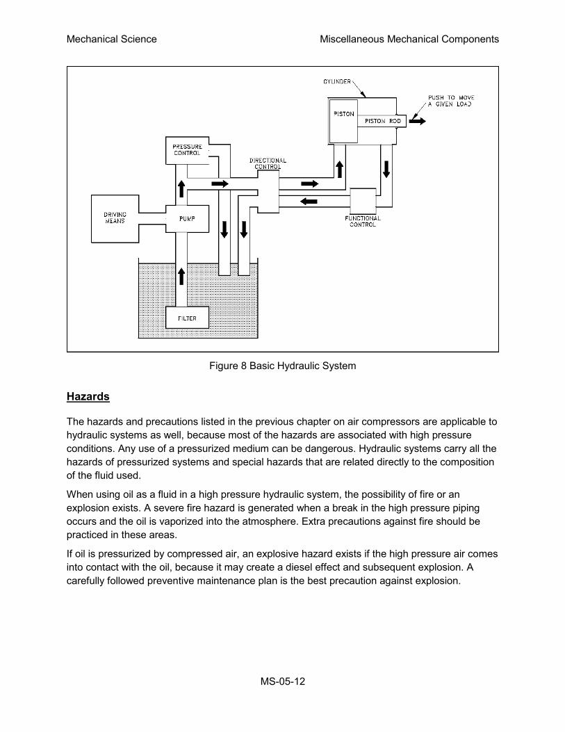
The operation of a typical hydraulic system is illustrated in Figure 8. Oil from a tank or reservoir
flows through a pipe into a pump. Often a filter is provided on the pump suction to remove
impurities from the oil. The pump, usually a gear-type, positive displacement pump, can be
driven by an electric motor, air motor, gas or steam turbine, or an internal combustion engine.
The pump increases the pressure of the oil. The actual pressure developed depends upon the
design of the system.
Most hydraulic systems have some method of preventing overpressure. As seen in Figure 8,
one method of pressure control involves returning hydraulic oil to the oil reservoir. The pressure
control box shown on Figure 8 is usually a relief valve that provides a means of returning oil to
the reservoir upon overpressurization.
The high pressure oil flows through a control valve (directional control). The control valve
changes the direction of oil flow, depending upon the desired direction of the load. In Figure 8
the load can be moved to the left or to the right by changing the side of the piston to which the
oil pressure is applied. The oil that enters the cylinder applies pressure over the area of the
piston, developing a force on the piston rod. The force on the piston rod enables the movement
of a load or device. The oil from the other side of the piston returns to a reservoir or tank.
Mechanical Science Miscellaneous Mechanical Components
MS-05-12
Figure 8 Basic Hydraulic System
Hazards
The hazards and precautions listed in the previous chapter on air compressors are applicable to
hydraulic systems as well, because most of the hazards are associated with high pressure
conditions. Any use of a pressurized medium can be dangerous. Hydraulic systems carry all the
hazards of pressurized systems and special hazards that are related directly to the composition
of the fluid used.
When using oil as a fluid in a high pressure hydraulic system, the possibility of fire or an
explosion exists. A severe fire hazard is generated when a break in the high pressure piping
occurs and the oil is vaporized into the atmosphere. Extra precautions against fire should be
practiced in these areas.
If oil is pressurized by compressed air, an explosive hazard exists if the high pressure air comes
into contact with the oil, because it may create a diesel effect and subsequent explosion. A
carefully followed preventive maintenance plan is the best precaution against explosion.

Mechanical Science Miscellaneous Mechanical Components
MS-05-13
Summary
The important information in this chapter is summarized below.
Hydraulics Summary
The relationship between pressure and force in a hydraulic piston is expressed
mathematically as:
F = P x A
where:
F = force
P = pressure
A = area
Oil from a tank or reservoir flows through a pipe into a pump. The pump can be
driven by a motor, turbine, or an engine. The pump increases the pressure of the
oil.
The high pressure oil flows in the piping through a control valve. The control
valve changes the direction of the oil flow. A relief valve, set at a desired safe
operating pressure, protects the system from an overpressure condition. Oil
entering the cylinder applies pressure to the piston, developing a force on the
piston rod.
The force on the piston rod enables the movement of a load or device. The oil
from the other side of the piston returns to a reservoir or tank via a filter, which
removes foreign particles.
Mechanical Science Miscellaneous Mechanical Components
MS-05-14
BOILERS
Boilers are commonly used at large facilities to act as primary or backup steam
sources. The source of heat that generates the steam varies, but the basic operation
of the boiler is the same. This chapter will summarize the operation of a boiler.
EO 1.7 DESCRIBE the basic operation of a boiler.
EO 1.8 IDENTIFY the following components of a typical boiler:
a. Steam drum d. Downcomer
b. Distribution header(s) e. Risers
c. Combustion chamber
Introduction
The primary function of a boiler is to produce steam at a given pressure and temperature. To
accomplish this, the boiler serves as a furnace where air is mixed with fuel in a controlled
combustion process to release large quantities of heat. The pressure-tight construction of a
boiler provides a means to absorb the heat from the combustion and transfer this heat to raise
water to a temperature such that the steam produced is of sufficient temperature and quality
(moisture content) for steam loads.
Boilers
Two distinct heat sources used for boilers are electric probes and burned fuel (oil, coal, etc.)
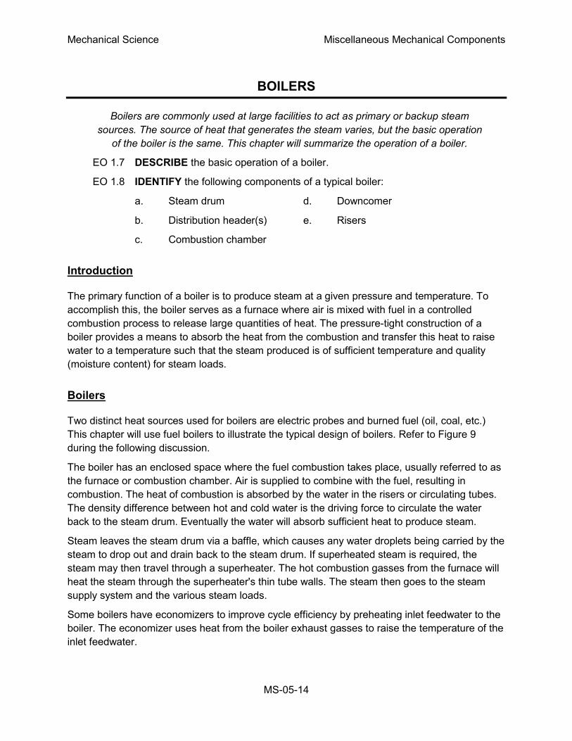
This chapter will use fuel boilers to illustrate the typical design of boilers. Refer to Figure 9
during the following discussion.
The boiler has an enclosed space where the fuel combustion takes place, usually referred to as
the furnace or combustion chamber. Air is supplied to combine with the fuel, resulting in
combustion. The heat of combustion is absorbed by the water in the risers or circulating tubes.
The density difference between hot and cold water is the driving force to circulate the water
back to the steam drum. Eventually the water will absorb sufficient heat to produce steam.
Steam leaves the steam drum via a baffle, which causes any water droplets being carried by the
steam to drop out and drain back to the steam drum. If superheated steam is required, the
steam may then travel through a superheater. The hot combustion gasses from the furnace will
heat the steam through the superheater's thin tube walls. The steam then goes to the steam
supply system and the various steam loads.
Some boilers have economizers to improve cycle efficiency by preheating inlet feedwater to the
boiler. The economizer uses heat from the boiler exhaust gasses to raise the temperature of the
inlet feedwater.

Mechanical Science Miscellaneous Mechanical Components
MS-05-15
Figure 9 Typical Fuel Boiler
Fuel Boiler Components
Figure 9 illustrates a typical fuel boiler. Some of the components are explained below.

Mechanical Science Miscellaneous Mechanical Components
MS-05-16
Steam drum The steam drum separates the steam from the
heated water. The water droplets fall to the bottom of
the tank to be cycled again, and the steam leaves the
drum and enters the steam system. Feedwater enters
at the bottom of the drum to start the heating cycle.
Downcomers Downcomers are the pipes in which the water from
the steam drum travels in order to reach the bottom of
the boiler where the water can enter the distribution
headers.
Distribution headers The distribution headers are large pipe headers that
carry the water from the downcomers to the risers.
Risers The piping or tubes that form the combustion
chamber enclosure are called risers. Water and
steam run through these to be heated. The term
risers refers to the fact that the water flow direction is
from the bottom to the top of the boiler. From the
risers, the water and steam enter the steam drum and
the cycle starts again.
Combustion chamber Located at the bottom of a boiler, the combustion
chamber is where the air and fuel mix and burn. It is
lined with the risers.

Mechanical Science Miscellaneous Mechanical Components
MS-05-17
Summary
The important information in this chapter is summarized below.
Boilers Summary
Boilers are vessels that allow water in contained piping to be heated to steam by
a heat source internal to the vessel. The water is heated to the boiling point. The
resulting steam separates, and the water is heated again. Some boilers use the
heat from combustion off-gasses to further heat the steam (superheat) and/or to
preheat the feedwater.
The following components were discussed:
The steam drum is where the steam is separated from the heated water.
Downcomers are the pipes in which the water from the steam drum travels to
reach the bottom of the boiler.
Distribution headers are large pipe headers that carry the water from the
downcomers to the risers.
Risers are the piping or tubes that form the combustion chamber enclosure.
Water and steam run through the risers to be heated.
The combustion chamber is located at the bottom of the boiler and is where the
air and fuel mix and burn.

Mechanical Science Miscellaneous Mechanical Components
MS-05-18
COOLING TOWERS
In an effort to lower costs and meet new environmental regulations, companies
are developing new ways to do things. One of the developments which meets
both cost decrease and environmental awareness is the cooling tower. This
chapter will summarize the advantages of cooling towers and how they function.
EO 1.9 STATE the purpose of cooling towers.
EO 1.10 DESCRIBE the operation of the following types of cooling towers:
a. Forced draft
b. Natural convection
Purpose
Before the development of cooling towers, rivers, lakes, and cooling ponds were required to
supply cooling. Through the development of the mechanical draft cooling tower, as little as one
square foot of area is needed for every 1000 square feet required for a cooling pond or lake.
Cooling towers minimize the thermal pollution of the natural water heat sinks and allow the
reuse of circulating water. An example of the manner in which a cooling tower can fit into a
system is shown in Figure 10.
Figure 10 Cooling System Containing Cooling Tower
The cooling of the water in a cooling tower is accomplished by the direct contact of water and
air. This cooling effect is provided primarily by an exchange of latent heat of vaporization
resulting from evaporation of a small amount of water and by a transfer of sensible heat, which
raises the temperature of the air. The heat transferred from the water to the air is dissipated to
the atmosphere.

Mechanical Science Miscellaneous Mechanical Components
MS-05-19
Induced Draft Cooling Towers
Induced draft cooling towers, illustrated in Figure 11, are constructed such that the incoming
circulating water is dispersed throughout the cooling tower via a spray header. The spray is
directed down over baffles that are designed to maximize the contact between water and air.
The air is drawn through the baffled area by large circulating fans and causes the evaporation
and the cooling of the water.
Figure 11 Induced Draft Cooling Tower
The nomenclature for induced draft cooling towers, including some items not illustrated in Figure
11 is summarized below.
Casing The casing encloses the walls of the cooling tower, exclusive of
fan deck and louvers.
Collecting basin The collecting basin is a receptacle beneath the cooling tower for
collecting the water cooled by the cooling tower. It can be made of
concrete, wood, metal, or an alternative material. Certain
necessary accessories are required such as sump, strainers,
overflow, drain, and a makeup system.
Drift eliminators The drift eliminators are parallel blades of PVC, wood, metal, or
an alternative material arranged on the air discharge side of the fill
to remove entrained water droplets from the leaving air stream.

Mechanical Science Miscellaneous Mechanical Components
MS-05-20
Driver The driver is a device that supplies power to turn the fan. It is
usually an electric motor, but turbines and internal combustion
engines are occasionally used.
Drive shaft The drive shaft is a device, including couplings, which transmits
power from the driver to the speed reducer.
Fan The fan is a device used to induce air flow through the cooling
tower.
Fan deck The fan deck is a horizontal surface enclosing the top of the cooling
tower above the plenum that serves as a working platform for
inspection and maintenance.
Fan stack The fan stack is a cylinder enclosing the fan, usually with an eased
inlet and an expanding discharge for increased fan efficiency.
Fill The fill is PVC, wood, metal, or an alternative material that provides
extended water surface exposure for evaporative heat transfer.
Intake louvers The intake louvers are an arrangement of horizontal blades at the
air inlets that prevent escape of falling water while allowing the
entry of air.
Makeup valve The makeup valve is a valve that introduces fresh water into the
collection basin to maintain the desired collecting basin water level.
Overflow The overflow is a drain that prevents the collecting basin from
overflowing.
Partition The partition is a baffle within a multi-cell cooling tower that is used
to prevent air and/or water flow between adjacent cells.
Plenum The plenum is the internal cooling tower area between the drift
eliminators and the fans.
Speed reducer The speed reducer is a right-angle gear box that transmits power to
the fan while reducing the driver speed to that required for optimal
fan performance.
Sump The sump is a depressed portion of the collecting basin from which
cold water is drawn to be returned to the connected system. The
sump usually contains strainer screens, antivortex devices, and a
drain or cleanout connection.
Distribution system The distribution system is that portion of a cooling tower that
distributes water over the fill area. It usually consists of one or more
flanged inlets, flow control valves, internal headers, distribution
basins, spray branches, metering orifices, and other related
components.

Mechanical Science Miscellaneous Mechanical Components
MS-05-21
Forced Draft Cooling Towers
Forced draft cooling towers are very similar to induced draft cooling towers. The primary
difference is that the air is blown in at the bottom of the tower and exits at the top. Forced draft
cooling towers are the forerunner to induced draft cooling towers. Water distribution problems
and recirculation difficulties discourage the use of forced draft cooling towers.
Natural Convection Cooling Towers
Figure 12 Natural Convection Cooling Tower
Natural convection cooling towers, illustrated in Figure 12, use the principle of convective flow to
provide air circulation. As the air inside the tower is heated, it rises through the tower. This
process draws more air in, creating a natural air flow to provide cooling of the water. The basin
at the bottom of the tower is open to the atmosphere. The cooler, more dense air outside the
tower will flow in at the bottom and contribute to the air circulation within the tower. The air
circulation will be self perpetuating due to the density difference between the warmer air inside
and the cooler air outside.

Mechanical Science Miscellaneous Mechanical Components
MS-05-22
The incoming water is sprayed around the circumference of the tower and cascades to the
bottom. The natural convection cooling towers are much larger than the forced draft cooling
towers and cost much more to construct. Because of space considerations and cost, natural
convection cooling towers are built less frequently than other types.
Summary
The important information in this chapter is summarized below.
Cooling Towers Summary
The cooling tower removes heat from water used in cooling systems within the plant.
The heat is released to the air rather than to a lake or stream. This allows facilities to
locate in areas with less water available because the cooled water can be recycled. It
also aids environmental efforts by not contributing to thermal pollution.
Induced draft cooling towers use fans to create a draft that pulls air through the cooling
tower fill. Because the water to be cooled is distributed such that it cascades over the
baffles, the air blows through the water, cooling it.
Forced draft cooling towers blow air in at the bottom of the tower. The air exits at the
top of the tower. Water distribution and recirculation difficulties limit their use.
Natural convection cooling towers function on the basic principle that hot air rises. As
the air inside the tower is heated, it rises through the tower. This process draws more
air in, creating a natural air flow to provide cooling of the water.
Mechanical Science Miscellaneous Mechanical Components
MS-05-23
DEMINERALIZERS
The cost of corrosion and radioactive contamination caused by poor water quality
in nuclear facilities is enormous. Demineralizers are an intricate part of water
quality control. The chemical theory of demineralizers is detailed in the Chemistry
Fundamentals Handbook. This chapter will address the mechanics of how
demineralizers operate.
EO 1.11 STATE the purpose of a demineralizer.
Purpose of Demineralizers
Dissolved impurities in power plant fluid systems generate corrosion problems and decrease
efficiency due to fouled heat transfer surfaces. Demineralization of the water is one of the most
practical and common methods available to remove these dissolved impurities.
In the plant, demineralizers (also called ion-exchangers) are used to hold ion exchange resins
and transport water through them. Ion exchangers are generally classified into two groups:
single-bed ion exchangers and mixed-bed ion exchangers.
Demineralizers
A demineralizer is basically a cylindrical tank with connections at the top for water inlet and resin
addition, and connections at the bottom for the water outlet. The resin can usually be changed
through a connection at the bottom of the tank. The resin beads are kept in the demineralizer by
upper and lower retention elements, which are strainers with a mesh size smaller then the resin
beads. The water to be purified enters the top at a set flow rate and flows down through the
resin beads, where the flow path causes a physical filter effect as well as a chemical ion
exchange.
Single-Bed Demineralizers
A single-bed demineralizer contains either cation or anion resin beads. In most cases, there are
two, single-bed ion exchangers in series; the first is a cation bed and the second is an anion
bed. Impurities in plant water are replaced with hydrogen ions in the cation bed and hydroxyl
ions in the anion bed. The hydrogen ions and the hydroxyl ions then combine to form pure
water. The Chemistry Handbook, Module 4, Principles of Water Treatment, addresses the
chemistry of demineralizers in more detail.
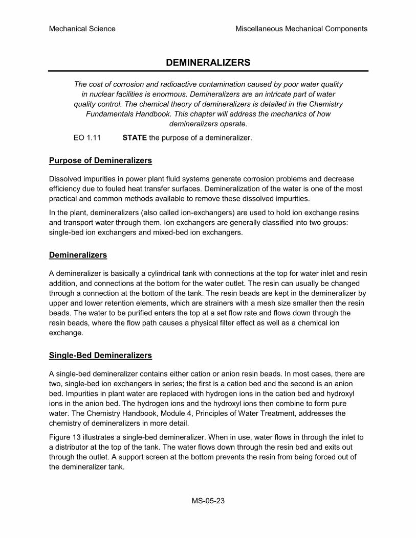
Figure 13 illustrates a single-bed demineralizer. When in use, water flows in through the inlet to
a distributor at the top of the tank. The water flows down through the resin bed and exits out
through the outlet. A support screen at the bottom prevents the resin from being forced out of
the demineralizer tank.

Mechanical Science Miscellaneous Mechanical Components
MS-05-24
Figure 13 Single-Bed Demineralizer
Single-Bed Regeneration
The regeneration of a single-bed ion exchanger is a three-step process. The first step is a
backwash, in which water is pumped into the bottom of the ion exchanger and up through the
resin. This fluffs the resin and washes out any entrained particles. The backwash water goes
out through the normal inlet distributor piping at the top of the tank, but the valves are set to
direct the stream to a drain so that the backwashed particles can be pumped to a container for
waste disposal.
The second step is the actual regeneration step, which uses an acid solution for cation units and
caustic solution for anion units. The concentrated acid or caustic is diluted to approximately 10%
with water by opening the dilution water valve, and is then introduced through a distribution
system immediately above the resin bed. The regenerating solution flows through the resin and
out the bottom of the tank to the waste drain.
The final step is a rinsing process, which removes any excess regenerating solution. Water is
pumped into the top of the tank, flows down through the resin bed and out at the bottom drain.
To return the ion exchanger to service, the drain valve is closed, the outlet valve is opened, and
the ion exchanger is ready for service.
Single-bed demineralizers are usually regenerated "in place." The resins are not pumped out to
another location for regeneration. The regeneration process is the same for cation beds and for
anion beds; only the regenerating solution is different. It is important to realize that if the ion

Mechanical Science Miscellaneous Mechanical Components
MS-05-25
exchanger has been exposed to radioactive materials, the backwash, regeneration, and rinse
solutions may be highly radioactive and must be treated as a radioactive waste.
Mixed-Bed Demineralizer
A mixed-bed demineralizer is a demineralizer in which the cation and anion resin beads are
mixed together. In effect, it is equivalent to a number of two-step demineralizers in series. In a
mixed-bed demineralizer, more impurities are replaced by hydrogen and hydroxyl ions, and the
water that is produced is extremely pure. The conductivity of this water can often be less than
0.06 micromhos per centimeter.
Mixed-Bed Regeneration
The mixed-bed demineralizer shown in Figure 14 is designed to be regenerated in place, but the
process is more complicated than the regeneration of a single-bed ion exchanger. The steps in
the regeneration are shown in Figure 14.
Figure 14a shows the mixed-bed ion exchanger in the operating, or on-line mode. Water enters
through a distribution header at the top and exits through the line at the bottom of the vessel.
Regeneration causes the effluent water to increase in electrical conductivity.
The first regeneration step is backwash, as shown in Figure 14b. As in a single-bed unit,
backwash water enters the vessel at the bottom and exits through the top to a drain. In addition
to washing out entrained particles, the backwash water in a mixed-bed unit must also separate
the resins into cation and anion beds. The anion resin has a lower specific gravity than the
cation resin; therefore, as the water flows through the bed, the lighter anion resin beads float
upward to the top. Thus, the mixed-bed becomes a split bed. The separation line between the
anion bed at the top and the cation bed at the bottom is called the resin interface. Some resins
can be separated only when they are in the depleted state; other resins separate in either the
depleted form or the regenerated form.
The actual regeneration step is shown in Figure 14c. Dilution water is mixed with caustic
solution and introduced at the top of the vessel, just above the anion bed. At the same time,
dilution water is mixed with acid and introduced at the bottom of the vessel, below the cation
bed. The flow rate of the caustic solution down to the resin interface is the same as the flow rate
of the acid solution up to the resin interface. Both solutions are removed at the interface and
dumped to a drain.
During the regeneration step, it is important to maintain the cation and anion resins at their
proper volume. If this is not done, the resin interface will not occur at the proper place in the
vessel, and some resin will be exposed to the wrong regenerating solution. It is also important to
realize that if the ion exchanger has been involved with radioactive materials, both the
backwash and the regenerating solutions may be highly radioactive and must be treated as
liquid radioactive waste.

Mechanical Science Miscellaneous Mechanical Components
MS-05-26
Figure 14 Regeneration of a Mixed-Bed Demineralizer
The next step is the slow rinse step, shown in Figure 14d, in which the flow of dilution water is
continued, but the caustic and acid supplies are cut off. During this two-direction rinse, the last
of the regenerating solutions are flushed out of the two beds and into the interface drain.
Rinsing from two directions at equal flow rates keeps the caustic solution from flowing down into
the cation resin and depleting it.
In the vent and partial drain step, illustrated in Figure 14e, the drain valve is opened, and some
of the water is drained out of the vessel so that there will be space for the air that is needed to
re-mix the resins. In the air mix step, (Figure 14f) air is usually supplied by a blower, which
forces air in through the line entering the bottom of the ion exchanger. The air mixes the resin
beads and then leaves through the vent in the top of the vessel. When the resin is mixed, it is
Mechanical Science Miscellaneous Mechanical Components
MS-05-27
dropped into position by slowly draining the water out of the interface drain while the air mix
continues.
In the final rinse step, shown in Figure 14g, the air is turned off and the vessel is refilled with
water that is pumped in through the top. The resin is rinsed by running water through the vessel
from top to bottom and out the drain, until a low conductivity reading indicates that the ion
exchanger is ready to return to service.
External Regeneration
Some mixed-bed demineralizers are designed to be regenerated externally, with the resins
being removed from the vessel, regenerated, and then replaced. With this type of demineralizer,
the first step is to sluice the mixed bed with water (sometimes assisted by air pressure) to a
cation tank in a regeneration facility. The resins are backwashed in this tank to remove
suspended solids and to separate the resins. The anion resins are then sluiced to an anion tank.
The two batches of separated resins are regenerated by the same techniques used for single-
bed ion exchangers. They are then sluiced into a holding tank where air is used to remix them.
The mixed, regenerated, resins are then sluiced back to the demineralizer.
External regeneration is typically used for groups of condensate demineralizers. Having one
central regeneration facility reduces the complexity and cost of installing several demineralizers.
External regeneration also allows keeping a spare bed of resins in a holding tank. Then, when a
demineralizer needs to be regenerated, it is out of service only for the time required to sluice out
the depleted bed and sluice a fresh bed in from the holding tank. A central regeneration facility
may also include an ultrasonic cleaner that can remove the tightly adherent coating of dirt or
iron oxide that often forms on resin beads. This ultrasonic cleaning reduces the need for
chemical regeneration.
Mechanical Science Miscellaneous Mechanical Components
MS-05-28
Summary
The important information in this chapter is summarized below.
Demineralizers Summary
Demineralization of water is one of the most practical and common methods used to
remove dissolved contaminates. Dissolved impurities in power plant fluid systems can
generate corrosion problems and decrease efficiency due to fouled heat transfer
surfaces. Demineralizers (also called ion-exchangers) are used to hold ion exchange
resins and transport water through them. Ion exchangers are generally classified into
two groups: single-bed ion exchangers and mixed-bed ion exchangers.
A demineralizer is basically a cylindrical tank with connections at the top for water inlet
and resin addition, and connections at the bottom for the water outlet. The resin can
usually be changed out through a connection at the bottom of the tank. The resin beads
are kept in the demineralizer by upper and lower retention elements, which are
strainers with a mesh size smaller then the resin beads.
The water to be purified enters the top at a set flow rate, flows down through the resin
beads where the flow path causes a physical filter effect as well as a chemical ion
exchange. The chemistry of the resin exchange is explained in detail in the Chemistry
Fundamentals Handbook.
There are two types of demineralizers, single-bed and mixed-bed. Single-bed
demineralizers have resin of either cation or anion exchange sites. Mixed-bed
demineralizers contain both anion and cation resin.
All demineralizers will eventually be exhausted from use. To regenerate the resin and
increase the demineralizer's efficiency, the demineralizers are regenerated. The
regeneration process is slightly different for a mixed-bed demineralizer compared to the
single-bed demineralizer. Both methods were explained in this chapter.

Mechanical Science Miscellaneous Mechanical Components
MS-05-29
PRESSURIZERS
Pressurizers are used for reactor system pressure control. The pressurizer is the
component that allows a water system, such as the reactor coolant system in a
PWR facility, to maintain high temperatures without boiling. The function of
pressurizers is discussed in this chapter.
EO 1.12 STATE the four purposes of a pressurizer.
EO 1.13 DEFINE the following terms attributable to a dynamic pressurizer system:
a. Spray nozzle c. Outsurge
b. Insurge d. Surge volume
Introduction
There are two types of pressurizers: static and dynamic. A static pressurizer is a partially filled
tank with a required amount of gas pressure trapped in the void area. A dynamic pressurizer is
a tank in which its saturated environment is controlled through use of heaters (to control
temperature) and sprays (to control pressure).
This chapter focuses on the dynamic pressurizer. A dynamic pressurizer utilizes a controlled
pressure containment to keep high temperature fluids from boiling, even when the system
undergoes abnormal fluctuations.
Before discussing the purpose, construction, and operation of a pressurizer, some preliminary
information about fluids will prove helpful.
The evaporation process is one in which a liquid is converted into a vapor at temperatures
below the boiling point. All the molecules in the liquid are continuously in motion. The molecules
that move most quickly possess the greatest amount of energy. This energy occasionally
escapes from the surface of the liquid and moves into the atmosphere. When molecules move
into the atmosphere, the molecules are in the gaseous, or vapor, state.
Liquids at a high temperature have more molecules escaping to the vapor state, because the
molecules can escape only at higher speeds. If the liquid is in a closed container, the space
above the liquid becomes saturated with vapor molecules, although some of the molecules
return to the liquid state as they slow down. The return of a vapor to a liquid state is called
condensation. When the amount of molecules that condense is equal to the amount of
molecules that evaporate, there is a dynamic equilibrium between the liquid and the vapor.
Pressure exerted on the surface of a liquid by a vapor is called vapor pressure. Vapor pressure
increases with the temperature of the liquid until it reaches saturation pressure, at which time
the liquid boils. When a liquid evaporates, it loses its most energetic molecules, and the average
energy per molecule in the system is lowered. This causes a reduction in the temperature of the
liquid.

Mechanical Science Miscellaneous Mechanical Components
MS-05-30
Boiling is the activity observed in a liquid when it changes from the liquid phase to the vapor
phase through the addition of heat. The term saturated liquid is used for a liquid that exists at its
boiling point. Water at 212oF and standard atmospheric pressure is an example of a saturated
liquid.
Saturated steam is steam at the same temperature and pressure as the water from which it was
formed. It is water, in the form of a saturated liquid, to which the latent heat of vaporization has
been added. When heat is added to a saturated steam that is not in contact with liquid, its
temperature is increased and the steam is superheated. The temperature of superheated
steam, expressed as degrees above saturation, is called degrees of superheat.
General Description
The pressurizer provides a point in the reactor system where liquid and vapor can be
maintained in equilibrium under saturated conditions, for control purposes. Although designs
differ from facility to facility, a typical pressurizer is designed for a maximum of about 2500 psi
and 680°F.
Dynamic Pressurizers
A dynamic pressurizer serves to:
maintain a system's pressure above its saturation point,
provide a means of controlling system fluid expansion and contraction,
provide a means of controlling a system's pressure, and
provide a means of removing dissolved gasses from the system by venting the
vapor space of the pressurizer.
Construction
A dynamic pressurizer is constructed from a tank equipped with a heat source such as electric
heaters at its base, a source of cool water, and a spray nozzle. A spray nozzle is a device
located in the top of the pressurizer that is used to atomize the incoming water.
A dynamic pressurizer must be connected in the system to allow a differential pressure to exist
across it. The bottom connection, also called the surge line, is the lower of the two pressure
lines. The top connection, referred to as the spray line, is the higher pressure line. Differential
pressure is obtained by connecting the pressurizer to the suction and discharge sides of the
pump servicing the particular system. Specifically, the surge (bottom connection) is connected
to the pump's suction side; the spray line (top connection) is connected to the pump's discharge
side. A basic pressurizer is illustrated in Figure 15.

Mechanical Science Miscellaneous Mechanical Components
MS-05-31
Figure 15 Basic Pressurizer
The hemispherical top and bottom
heads are usually constructed of carbon
steel, with austenitic stainless steel
cladding on all surfaces exposed to the
reactor system water.
The pressurizer can be activated in two
ways. Partially filling the pressurizer
with system water is the first. After the
water reaches a predetermined level,
the heaters are engaged to increase
water temperature. When the water
reaches saturation temperature, it
begins to boil. Boiling water fills the void
above the water level, creating a
saturated environment of water and
steam. The other method involves filling
the pressurizer completely, heating the
water to the desired temperature, then
partially draining the water and steam
mixture to create a steam void at the top
of the vessel.
Water temperature determines the
amount of pressure developed in the
steam space, and the greater the
amount of time the heaters are
engaged, the hotter the environment
becomes. The hotter the environment,
the greater the amount of pressure.
Installing a control valve in the spray
line makes it possible to admit cooler
water from the top of the pressurizer through the spray nozzle. Adding cooler water condenses
the steam bubble, lowers the existing water temperature, and reduces the amount of system
pressure.
Operation
The level of water within a pressurizer is directly dependant upon the temperature, and thus the
density, of the water in the system to which the pressurizer is connected. An increase in system
temperature causes the density of the water to decrease. This decreased density causes the
water to expand, causing the level of water to increase in the vessel. The increased level of
water in a pressurizer is referred to as an insurge. An insurge compresses the vapor space,
which in turn causes the system pressure to rise. This results in slightly superheated steam in

Mechanical Science Miscellaneous Mechanical Components
MS-05-32
contact with the subcooled pressurizer liquid. The superheated steam transfers heat to the liquid
and to the pressurizer walls. This re-establishes and maintains the saturated condition.
A decrease in system temperature causes the density to increase which causes the system
water volume to contract. The contraction (drop) in pressurizer water level and increase in vapor
space is referred to as an outsurge. The increase in vapor space causes the pressure to drop,
flashing the heated water volume and creating more steam. The increased amount of steam re-
establishes the saturated state. Flashing continues until the decrease in water level ceases and
saturated conditions are restored at a somewhat lower pressure.
In each case, the final conditions place the pressurizer level at a new value. The system
pressure remains at approximately its previous value, with relatively small pressure variations
during the level change, provided that the level changes are not too extreme.
In actual application, relying on saturation to handle all variations in pressure is not practical. In
conditions where the system water is surging into the pressurizer faster than the pressurizer can
accommodate for example, additional control is obtained by activating the spray. This spray
causes the steam to condense more rapidly, thereby controlling the magnitude of the pressure
rise.
When a large outsurge occurs, the level can drop rapidly and the water cannot flash to steam
fast enough. This results in a pressure drop. The installed heaters add energy to the water and
cause it to flash to steam faster, thereby reducing the pressure drop. The heaters can also be
left on to re-establish the original saturation temperature and pressure. In certain designs,
pressurizer heaters are energized continuously to make up for heat losses to the environment.
The pressurizer's heater and spray capabilities are designed to compensate for the expected
surge volume. The surge volume is the volume that accommodates the expansion and
contraction of the system, and is designed to be typical of normal pressurizer performance.
Plant transients may result in larger than normal insurges and outsurges. When the surge
volume is exceeded, the pressurizer may fail to maintain pressure within normal operating
pressures.
Pressurizer operation, including spray and heater operation, is usually automatically controlled.
Monitoring is required in the event the control features fail, because the effect on the system
could be disastrous without operator action.
Mechanical Science Miscellaneous Mechanical Components
MS-05-33
Summary
The important information in this chapter is summarized below.
Pressurizer Summary
Two types of pressurizers -- static and dynamic
Purposes of a pressurizer:
o Maintains system pressure above saturation
o Provides a surge volume for system expansion and contraction
o Provides a means of controlling system pressure
o Provides a means of removing dissolved gases
A spray nozzle is a device located in the top of the pressurizer, used to atomize
incoming water to increase the effects of spraying water into the top of the pressurizer
to reduce pressure by condensing steam.
Insurge is the volume absorbed within the pressurizer during a level increase to
compensate for a rise in the system's temperature.
Outsurge is the volume released from the pressurizer during a level decrease to
compensate for a reduction in the system's temperature.
The surge volume is the volume of water that accommodates the expansion and
contraction of the system, and is designed to be typical of normal pressurizer
performance.

Mechanical Science Miscellaneous Mechanical Components
MS-05-34
STEAM TRAPS
Steam traps are installed in steam lines to drain condensate from the lines
without allowing the escape of steam. There are many designs of steam traps for
high and low pressure use.
EO 1.14 STATE the purpose and general operation of a steam trap.
EO 1.15 IDENTIFY the following types of steam traps:
a. Ball float steam trap c. Bucket steam trap
b. Bellow steam trap d. Impulse steam trap
General Operation
In general, a steam trap consists of a
valve and a device or arrangement that
causes the valve to open and close as
necessary to drain the condensate from
piping without allowing the escape of
steam. Steam traps are installed at low
points in the system or machinery to be
drained. Some types of steam traps that
are used in DOE facilities are described in
this chapter.
Ball Float Steam Trap
A ball float steam trap is illustrated in
Figure 16. The valve of this trap is
connected to the float in such a way that
the valve opens when the float rises.
When the trap is in operation, the steam
and any water that may be mixed with it
flows into the float chamber. The water, being heavier than the steam, falls to the bottom of the
trap, causing the water level to rise. As the water level rises, it lifts the float; thus lifting the valve
plug and opening the valve. The condensate drains out and the float moves down to a lower
position, closing the valve before the condensate level gets low enough to allow steam to
escape. The condensate that passes out of the trap is returned to the feed system.
Bucket Steam Trap
A bucket steam trap is illustrated in Figure 17. As condensate enters the trap body, the bucket
floats. The valve is connected to the bucket in such a way that the valve closes as the bucket
Figure 16 Ball Float Steam Trap

Mechanical Science Miscellaneous Mechanical Components
MS-05-35
rises. As condensate continues to flow into
the trap body, the valve remains closed
until the bucket is full. When the bucket is
full, it sinks and thus opens the valve. The
valve remains open until enough
condensate has passed out to allow the
bucket to float, and closing the valve.
Thermostatic Steam Traps
There are several kinds of thermostatic
steam traps in use. In general, these traps
are more compact and have fewer moving
parts than most mechanical steam traps.
Bellows-Type Steam Trap
A bellows-type steam trap is illustrated in Figure 18. The operation of this trap is controlled by
the expansion of the vapor of a volatile liquid, which is enclosed in a bellows-type element.
Steam enters the trap body and heats the volatile liquid in the sealed bellows, causing
expansion of the bellows.
Figure 18 Bellows-Type Steam Trap
The valve is attached to the bellows in such a way that the valve closes when the bellows
expands. The valve remains closed, trapping steam in the valve body. As the steam cools and
condenses, the bellows cools and contracts, thereby opening the valve and allowing the
condensate to drain.
Figure 17 Bucket Steam Trap

Mechanical Science Miscellaneous Mechanical Components
MS-05-36
Impulse Steam Trap
Impulse steam traps, illustrated in Figure 19, pass steam and condensate through a strainer
before entering the trap. A circular baffle keeps the entering steam and condensate from
impinging on the cylinder or on the disk. The impulse type of steam trap is dependent on the
principle that hot water under pressure tends to flash into steam when the pressure is reduced.
Figure 19 Impulse Steam Trap
The only moving part in the steam trap is the disk. A flange near the top of the disk acts as a
piston. As demonstrated in Figure 19, the working surface above the flange is larger than the
working surface below the flange.
A control orifice runs through the disk from top to bottom, which is considerably smaller at the
top than at the bottom. The bottom part of the disk extends through and beyond the orifice in the
seat. The upper part of the disk (including the flange) is inside a cylinder. The cylinder tapers
inward, so the amount of clearance between the flange and the cylinder varies according to the
position of the valve. When the valve is open, the clearance is greater than when the valve is
closed.

Mechanical Science Miscellaneous Mechanical Components
MS-05-37
When the trap is first placed in service, pressure from the inlet (chamber A) acts against the
underside of the flange and lifts the disk off the valve seat. Condensate is thus allowed to pass
out through the orifice in the seat; and, at the same time, a small amount of condensate (called
control flow) flows up past the flange and into chamber B. The control flow discharges through
the control orifice, into the outlet side of the trap, and the pressure in chamber B remains lower
than the pressure in chamber A.
As the line warms up, the temperature of the condensate flowing through the trap increases.
The reverse taper of the cylinder varies the amount of flow around the flange until a balanced
position is reached in which the total force exerted above the flange is equal to the total force
exerted below the flange. It is important to note that there is still a pressure difference between
chamber A and chamber B. The force is equalized because the effective area above the flange
is larger than the effective area below the flange. The difference in working area is such that the
valve maintains at an open, balanced, position when the pressure in chamber B is
approximately 86% of the pressure in chamber A.
As the temperature of the condensate approaches its boiling point, some of the control flow
going to chamber B flashes into steam as it enters the low pressure area. Because the steam
has a much greater volume than the water from which it is generated, pressure builds up in the
space above the flange (chamber B). When the pressure in this space is 86% of the inlet
pressure (chamber A), the force exerted on the top of the flange pushes the entire disk
downward and closes the valve. With the valve closed, the only flow through the trap is past the
flange and through the control orifice. When the temperature of the condensate entering the trap
drops slightly, condensate enters chamber B without flashing into steam. Pressure in chamber B
is thus reduced to the point where the valve opens and allows condensate to flow through the
orifice in the valve seat. The cycle is repeated continuously.
With a normal condensate load, the valve opens and closes at frequent intervals, discharging a
small amount of condensate at each opening. With a heavy condensate load, the valve remains
open and allows a continuous discharge of condensate.
Orifice-Type Steam Trap
DOE facilities may use continuous-flow steam traps of the orifice type in some constant service
steam systems, oil-heating steam systems, ventilation preheaters, and other systems or
services in which condensate forms at a fairly constant rate. Orifice-type steam traps are not
suitable for services in which the condensate formation is not continuous.
Although there are several variations of the orifice-type steam trap, each has one thing in
common; it contains no moving parts. One or more restricted passageways or orifices allow
condensate to trickle through, but do not allow steam to flow through. Some orifice-type steam
traps have baffles in addition to orifices.
Mechanical Science Miscellaneous Mechanical Components
MS-05-38
Summary
The following important information in this chapter is summarized below.
Steam Traps Summary
A steam trap consists of a valve and a device or arrangement that causes the valve to
open and close as necessary to drain the condensate from the lines without allowing
the escape of steam. Steam traps are installed at low points in the system or machinery
to be drained.
The type of steam trap used depends primarily on its application. Types include ball
float, bucket traps, thermostatic traps, bellows-type traps, impulse traps, and orifice-
type traps.
Impulse steam traps pass steam and condensate through a strainer before entering the
trap. A circular baffle keeps the entering steam and condensate from impinging on the
cylinder or on the disk. The impulse type of steam trap is dependent on the fact that hot
water under pressure tends to flash into steam when the pressure is reduced.

Mechanical Science Miscellaneous Mechanical Components
MS-05-39
FILTERS AND STRAINERS
When it is necessary to remove suspended solids from a liquid, the usual method
is to filter or strain the liquid. The two methods differ only in the size of the mesh
being used. Filtering removes the very small solids, and straining removes the
larger solids. Because filtering and straining are for all practical purposes the
same, this chapter will differentiate the two terms on the basis of application of
the filter or strainer.
EO 1.16 DESCRIBE each of the following types of strainers and filters, including
an example of typical use.
a. Cartridge filters d. Bucket strainer
b. Precoated filters e. Duplex strainer
c. Deep-bed filters
EO 1.17 EXPLAIN the application and operation of a strainer or filter backwash.
Introduction
Filtration is a process used to remove suspended solids from a solution. Other processes such
as demineralization remove ions or dissolved ions. Different filters and strainers are used for
different applications. In general, the filter passage must be small enough to catch the
suspended solids but large enough that the system can operate at normal system pressures
and flows. Filters and strainers are used throughout most DOE facilities. They are used in
hydraulic systems, oil systems, cooling systems, liquid waste disposal, water purification, and
reactor coolant systems.
Cartridge Filters
Figure 20 illustrates a typical multi-cartridge filter. The cartridges are cylinders and usually
consist of a fiber yarn wound around a perforated metal core. The liquid being filtered is forced
through the yarn, which is approximately 1/2 inch thick, and then through the perforations in the
metal core to the filter outlet, which can be at either end. A cartridge filter may include several
cartridges, the exact number depending on the liquid flow rate that must be handled.
In the filter assembly illustrated in Figure 21, the cartridges are held between plates so that the
water must pass through the layer of yarn to reach the filter outlet. The type of yarn that is used
depends on the application. Some of the fibers commonly used include resin-impregnated wool
or cellulose, cotton-viscose, polypropylene, nylon, and glass. In some applications that involve
high temperatures or pressures, porous metal cartridges are used. These cartridges are usually
made of 316 stainless steel, but inconel, monel, and nickel are also used.

Mechanical Science Miscellaneous Mechanical Components
MS-05-40
Figure 20 Typical Multi-Cartridge Filter
Depending on the fiber or metal that is used, cartridges are available that will filter out all particle
matter down to a specified size. For example, a certain cartridge might be designed to remove
all particles larger than 10 microns, one micron, or even 0.1 micron. (A micron is 10-3
millimeters.)
Cartridge filters have the advantage of
being relatively inexpensive to install and
operate. Instruments measure the
differential pressure across these filters to
let the operator know when a filter is
plugged and must be replaced. When the
cartridges are removed from radioactive
systems, the radiation levels can be very
high. For this reason, the cartridges may be
withdrawn into a shielded cask for moving
to a storage area or a solid waste
processing area. When the porous metal
cartridges become plugged, they can be
cleaned ultrasonically and reused. When
this is done, the cleaning solution becomes
contaminated and must be processed as liquid radioactive waste.
Another type of cartridge filter is the wafer, or disk filter. In this filter, disks are stacked to form a
cartridge and placed down over a central perforated pipe. Each disk is typically 1/8 inch to 1/4
inch thick and made of cellulose or asbestos fibers.
Liquid that enters the disk filter moves up around the outside of the stack of disks, is forced
between the disks, travels through the perforations in the central pipe, and then leaves the filter.
The filtering action takes place as the liquid is forced between the disks.
Figure 21 Cartridge Filter

Mechanical Science Miscellaneous Mechanical Components
MS-05-41
As with the smaller cartridges, if a disk filter is used to filter radioactive water, it may be very
radioactive when it is removed, and must be handled very carefully. One way to remove a disk
filter is by means of a crane, which lifts the filter out of its housing and moves it to a shielded
container. The disposal problem is one of the major disadvantages of cartridge and disk-
cartridge filters.
Precoat Filters
A precoat filter eliminates the problem of physically handling radioactive materials, because the
filter material (called the medium) can be installed and removed remotely. Inside the filter
housing is a bundle of septums (vertical tubes, on which the filter medium is deposited). The
septums in some filters are approximately 1 inch in diameter and 3 feet long and are usually
made of perforated or porous metal (normally stainless steel). There may be several hundred of
these septums in a filter. Septums in other filters are approximately 3 inches in diameter and 3
feet long and are made of porous stone or porous ceramic material. There are usually less than
100 of these larger septums in a filter.
The filtering medium fibers may be finely divided diatomite, perlite, asbestos, or cellulose.
Diatomite, the least expensive medium, is used to filter liquid waste that will be discharged from
the plant. Cellulose is generally used for processing water that will be returned to a reactor,
because diatomite can allow silica leaching.
When a precoat filter is in use, water that enters the filter vessel passes through the filter
medium that is deposited on the septums and then leaves through the outlet. Before the filter
can be placed into operation, however, the filter medium must be installed; that is, the filter must
be precoated.
The first step in precoating the filter is to close the inlet and outlet valves to the filter. The filter
medium used is mixed with demineralized water in an external mixing tank to form a slurry,
which is pumped through the filter. Some of the filter medium deposits on the septums and is
held there by the pressure of water on the outside of the septums. At the beginning of the
precoating process, some of the fibers of the filter medium pass through the septums, either
because they are smaller than the openings or because they pass through lengthwise. Thus,
there is still some filter medium in the water as it leaves the filter, so the slurry is recirculated
again and again until the water is clear. Clear water indicates that all of the filter medium is
deposited on the septums, and the filter is precoated.
One characteristic of the precoating process is that a very even layer of filter medium
(approximately 1/8 inch thick) is deposited on the septums. This occurs because the circulating
slurry follows the path of least resistance. When the coating at one point reaches a certain
thickness, the slurry takes the fibers to another point, and this process continues until
precoating is complete.
Because water pressure holds the filter in place, flow must be maintained through the
recirculating loop to keep the medium from falling off. This is called a holding flow. As the inlet
and outlet valves are opened for normal usage, called service flow, the holding flow is gradually
cut off.

Mechanical Science Miscellaneous Mechanical Components
MS-05-42
Backwashing Precoat Filters
After a filter has been precoated, it is put into service and kept on line until the pressure
differential indicates that the filter medium is becoming plugged. When this occurs, the old filter
medium is removed and the filter is precoated again. Filters are usually installed in pairs, so that
one filter can remain in service while the other is undergoing the filter backwashing and
precoating process.
Since water pressure helps to hold the filter medium against the septums, some of the old filter
medium will fall off as soon as this pressure is removed. Backwashing is used to remove the
filter medium that does not fall off. Backwashing is usually done in one of two ways. With some
filters, demineralized water is pumped backwards through the center of the septums, and the
filter medium coating is knocked off by the water as it comes out through the septums.
Most filters use a multi-step backwashing procedure. First, the inlet valve and the outlet valve
are closed, and the drain valve and the top vent are opened to allow the water to drain. Then
the drain valve and the vent are closed, and the inlet water valve is opened to raise the water
level. The filter is equipped with a special high-domed top to trap and compress air. When the
water inlet valve is closed and the drain valve is opened quickly, the compressed air forces
water down through the center of the septums. This water knocks the filter medium off of the
septums.
With both types of backwashing, the filter medium coating that is removed is sluiced out through
a drain line to a filter sludge tank, where it is stored for further processing. The filter is then
precoated again and put back into service.
With precoat filters, the type and quantity of filter medium is critical. If too little material or too
coarse a material is used, some of the finely divided crud in the water may get into the openings
of the septums. When the filter is backwashed, this crud is usually not removed. It continues to
build up during subsequent use of the filter until the septums become so plugged that they have
to be replaced.
If too much filter medium is used, the layer that builds up on the septums will bridge the area
between the septums. When the filter is backwashed, these bridges are usually not removed.
Therefore the bridging continues, and the filter runs become progressively shorter. Eventually,
the filter must be opened and the filter medium must be removed manually.
Precoat filters are much more complicated than cartridge filters, and the equipment required is
much more expensive to install and maintain. The major advantage of precoat filters is the
remote operation, which eliminates the physical handling of highly radioactive filter cartridges.
Deep-Bed Filters
Deep-bed filters are usually found only in makeup water systems, where they are used to filter
water after it has been treated in a clarifier. They are used to remove organic matter, chlorine,
and very fine particulate matter.
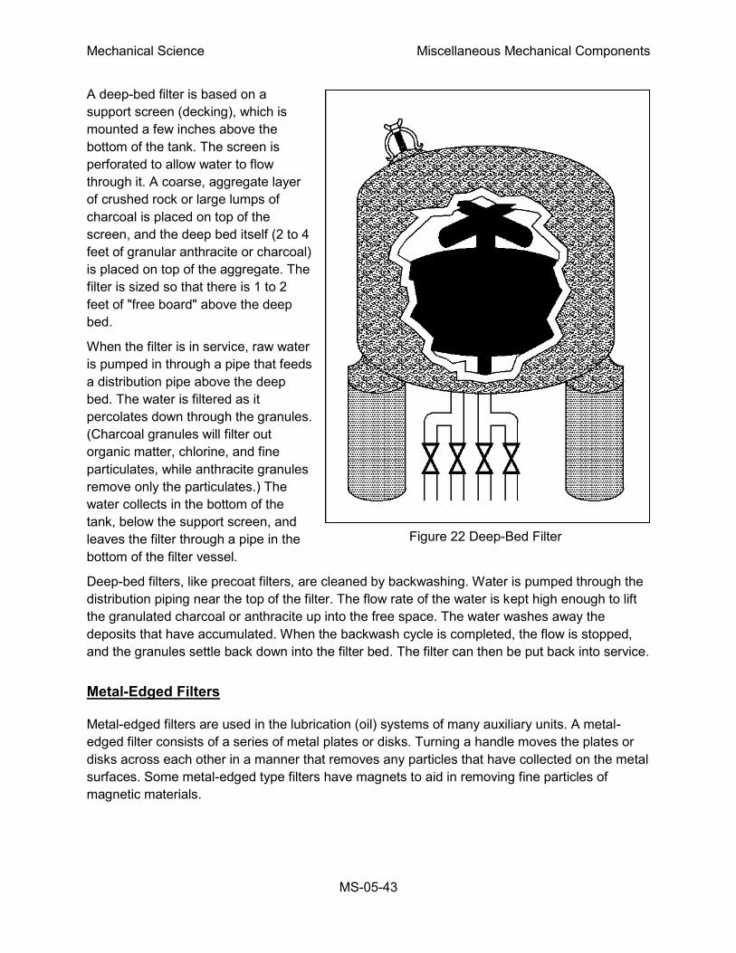
Mechanical Science Miscellaneous Mechanical Components
MS-05-43
A deep-bed filter is based on a
support screen (decking), which is
mounted a few inches above the
bottom of the tank. The screen is
perforated to allow water to flow
through it. A coarse, aggregate layer
of crushed rock or large lumps of
charcoal is placed on top of the
screen, and the deep bed itself (2 to 4
feet of granular anthracite or charcoal)
is placed on top of the aggregate. The
filter is sized so that there is 1 to 2
feet of "free board" above the deep
bed.
When the filter is in service, raw water
is pumped in through a pipe that feeds
a distribution pipe above the deep
bed. The water is filtered as it
percolates down through the granules.
(Charcoal granules will filter out
organic matter, chlorine, and fine
particulates, while anthracite granules
remove only the particulates.) The
water collects in the bottom of the
tank, below the support screen, and
leaves the filter through a pipe in the
bottom of the filter vessel.
Deep-bed filters, like precoat filters, are cleaned by backwashing. Water is pumped through the
distribution piping near the top of the filter. The flow rate of the water is kept high enough to lift
the granulated charcoal or anthracite up into the free space. The water washes away the
deposits that have accumulated. When the backwash cycle is completed, the flow is stopped,
and the granules settle back down into the filter bed. The filter can then be put back into service.
Metal-Edged Filters
Metal-edged filters are used in the lubrication (oil) systems of many auxiliary units. A metal-
edged filter consists of a series of metal plates or disks. Turning a handle moves the plates or
disks across each other in a manner that removes any particles that have collected on the metal
surfaces. Some metal-edged type filters have magnets to aid in removing fine particles of
magnetic materials.
Figure 22 Deep-Bed Filter

Mechanical Science Miscellaneous Mechanical Components
MS-05-44
Strainers
Strainers are fitted in many piping lines to prevent the passage of grit, scale, dirt, and other
foreign matter, which could obstruct pump suction valves, throttle valves, or other machinery
parts. One of the simplest and most common types of strainers found in piping systems is the Y-
strainer, which is illustrated in Figure 23.
Figure 23 Y-strainer
Figure 24 illustrates three additional common types of strainers. Part A shows a typical sump
pump suction bucket strainer located in the sump pump suction line between the suction
manifold and the pump. Any debris that enters the piping is collected in the strainer basket. The
basket can be removed for cleaning by loosening the strongback screws, removing the cover,
and lifting the basket out by its handle.
Figure 24 Common Strainers
Mechanical Science Miscellaneous Mechanical Components
MS-05-45
Part B of Figure 24 shows a duplex oil strainer commonly used in fuel oil and lubricating oil
lines, where it is essential to maintain an uninterrupted flow of oil. The flow may be diverted from
one basket to the other, while one is being cleaned.
Part C of Figure 24 shows a manifold steam strainer. This type of strainer is desirable where
space is limited, because it eliminates the use of separate strainers and their fittings. The cover
is located so that the strainer basket can be removed for cleaning.
Backwashing
If the filter or strainer cannot be easily removed for cleaning, the system design will usually
include a flowpath for backwashing. The backwashing of precoated filters has already been
explained because it is more complex than a typical backwash. The intent of a backwash is to
flow liquid in the opposite direction of normal flow, creating a pressure that pushes the debris off
the strainer or filter. The debris is flushed to a waste tank or drain.
Normally, to establish a backwash lineup, the flowpath upstream of the inlet to the strainer or
filter is closed, the flow path downstream of the outlet is closed, and a drain flowpath is opened.
The flush source is then opened and the flow goes into the outlet of the strainer or filter, through
the strainer or filter, and exits the inlet to the backwash drain or waste tank, carrying the debris
with it.
Mechanical Science Miscellaneous Mechanical Components
MS-05-46
Summary
The important information in this chapter is summarized below.
Filters and Strainers Summary
A cartridge filter may be a single cartridge or multi-cartridge filter. The cartridges are
cylinders that usually consist of a fiber yarn wound around a perforated metal core. The
liquid being filtered is forced through the yarn and then through the perforations in the
metal core to the filter outlet, which can be at either end. This type of filter is used to
remove fine particles in any flow condition. Radioactive systems may use these
because they are inexpensive and easy to replace.
Precoat filters consists of a filter housing that contains a bundle of septums, (vertical
tubes, on which the filter medium is deposited) usually made of perforated or porous
metal (normally stainless steel), porous stone, or porous ceramic material. The filtering
medium fibers may be finely divided diatomite, perlite, asbestos, or cellulose. Diatomite,
the least expensive medium, is used to filter liquid waste that will be discharged from
the plant. Cellulose is generally used for processing water that will be returned to the
reactor, because diatomite can allow silica leaching.
A deep-bed filter is based on a support screen (decking), which is mounted a few
inches above the bottom of the tank. The screen is perforated to allow water to flow
through it. A coarse, aggregate layer of crushed rock or large lumps of charcoal is
placed on top of the screen, and the deep bed itself (2 to 4 feet of granular anthracite or
charcoal) is placed on top of the aggregate. This type of filter is frequently used in raw
water treatment.
The bucket strainer is literally a bucket to catch debris. The bucket can be removed for
cleaning by loosening the strongback screws, removing the cover, and lifting the bucket
out by its handle. It is usually used in systems expected to have larger debris.
A duplex strainer is a strainer consisting of two sides with a basket in each side. Only
one side is placed in service at a time. These are commonly used in fuel oil and
lubricating oil lines, where it is essential to maintain an uninterrupted flow of oil. The
flow may be diverted from one basket to the other, while one is being cleaned.
If the filter or strainer cannot be easily removed for cleaning, the system design will
usually include a flowpath for backwashing. The intent of a backwash is to flow liquid in
the opposite direction of normal flow, creating a pressure that pushes the debris off the
strainer or filter. The debris is flushed to a waste tank or drain.
Normally, to establish a backwash lineup, the flowpath upstream of the inlet to the
strainer or filter is closed, the flow path downstream of the outlet is closed, and a drain
flowpath is opened. The flush source is then opened and the flow goes into the outlet of
the strainer or filter, through the strainer or filter, and exits the inlet to the backwash
drain or waste tank, carrying the debris with it.