Embed Size (px)
Citation preview


This pageintentionally left
blank

Copyright © 2009, New Age International (P) Ltd., PublishersPublished by New Age International (P) Ltd., Publishers
All rights reserved.No part of this ebook may be reproduced in any form, by photostat, microfilm,xerography, or any other means, or incorporated into any information retrievalsystem, electronic or mechanical, without the written permission of the publisher.All inquiries should be emailed to [email protected]
PUBLISHING FOR ONE WORLD
NEW AGE INTERNATIONAL (P) LIMITED, PUBLISHERS4835/24, Ansari Road, Daryaganj, New Delhi - 110002Visit us at www.newagepublishers.com
ISBN (13) : 978-81-224-2871-1

Dedicated
to
the student community who will usethis book

This pageintentionally left
blank

PREFACE
Mechanical Sciences-II, within the purview of WBUT syllabus, deals the fundamental aspects ofthermodynamics and fluid mechanics. Both of thermodynamics and fluid mechanics have separateidentity as full-fledged subjects. Hence to study both of them, the students of WBUT may need toseparate books. Here in a single book these two subjects’ matters are complied for the good ofstudents. To achieve an in-depth knowledge of these two basic subjects, it needs very lucid elaborationof the text and also presentation of numerous worked out examples for complete understanding ofthe topic. Keeping these basic requirements in mind, we have tried to exert our best to come up witha most useful book.
In this newly revised edition, we have tried to rectify the errors and omissions detected earlier.The present version mainly features
Thorough discussion of the topic in basic level, avoiding much detailing and critical discourse.
Inclusion of multiple choice questions relevant to the topic.
Provision of number of useful numerical examples for holistic understanding of the topic.
The forbearance as well as the active support of our family members and the useful suggestionsby our colleagues and the commendable support from the editorial team of the publishing houseconsorted successfully to bloom this project. Though proper care has been adopted to make the bookerror free, any unintended mistake or error or omission noticed may be directly communicated to thepublisher or the author(s).
Dr. Basudeb BhattacharyaProf. Subal Chandra Bera

This pageintentionally left
blank

This pageintentionally left
blank

This pageintentionally left
blank

Preface viiSyllabus ix
Group–A: Thermodynamics
CHAPTER 1: BASIC CONCEPT AND SOME DEFINITIONS 3–31
1.1 Introduction 31.2 Macroscopic and Microscopic Approach 31.3 Thermodynamic System 41.4 Classification of Thermodynamic Systems 41.5 Control Mass and Control Volume 61.6 Thermodynamic Co-ordinates 71.7 State of a System 71.8 Properties of a System 71.9 Classification of Properties of a System 71.10 Phase 81.11 Thermodynamic Equilibrium 81.12 Path 91.13 Process 91.14 Cyclic Process or Thermodynamic Cycle 101.15 Point Function and Path Function 121.16 Unit 131.17 Systems of Units 151.18 Mass (M) 151.19 Weight (W) 161.20 Force (F) 161.21 Specific Weight (W
S) 17
1.22 Specific Volume (vS) 17
CONTENTS

(xii) Mechanical Science-II
1.23 Pressure 171.24 Absolute, Gauge and Vacuum Pressure 171.25 Pressure Measurement by Manometer 181.26 Normal Temperature and Pressure (N.T.P) 201.27 Standard Temperature and Pressure (S.T.P) 201.28 Energy 201.29 Types of Stored Energy 201.30 Law of Conservation of Energy 211.31 Power 21
CHAPTER 2: ZEROTH LAW AND TEMPERATURE 33–57
2.1 Temperature 332.2 Zeroth Law of Thermodynamics 332.3 Measurement of Temperature 332.4 Constant Volume Gas Thermometer and Temperature Scale 342.5 Heat and Heat Transfer 372.6 Specific Heat 382.7 Thermal or Heat Capacity of a Substance 382.8 Water Equivalent of a Substance 392.9 Mechanical Equivalent of Heat 392.10 Work 392.11 Sign Convention of Work 412.12 Work Done During a Quasi-Static or Quasi-Equilibrium Process 412.13 Work and Heat Transfer—A Path Function 432.14 Comparison of Heat and Work 442.15 Example of Work 452.16 Work in Non-flow Process Versus Flow Process 50
CHAPTER 3: PROPERTIES AND THERMODYNAMIC PROCESSES OF GAS 59–102
3.1 Introduction 593.2 General Gas Equation 593.3 Equation of State and Characteristic Equation of Gas 603.4 Universal Gas Constant or Molar Gas Constant 603.5 Specific Heat of Gas 613.6 Linear Relation Between C
p and C
v62
3.7 Ratio of Cp and C
v62
3.8 Enthalpy of a Gas 633.9 Thermodynamic Processes 633.10 Classification of Thermodynamic Process 643.11 Heating and Expansion of Gases in Non-flow Process 643.12 Constant Volume or Isochoric Process 643.13 Constant Pressure or Isobaric Process 663.14 Hyperbolic Process 683.15 Constant Temperature or Isothermal Process 69

(xiii)Contents
3.16 Adiabatic Process 713.17 Polytropic Process 743.18 General Laws for Expansion and Compression 753.19 Real Gas 763.20 Real Gas and Compressibility Factor 763.21 Law of Corresponding State and Generalized Compressibility Chart 77
CHAPTER 4: FIRST LAW OF THERMODYNAMICS AND ITS APPLICATION 103–131
4.1 Introduction 1034.2 Joule’s Experiment 1034.3 First Law of Thermodynamics for a System Undergoing a Thermodynamics Cycle 1044.4 The Important Consequences of the First Law of Thermodynamics 1054.5 Limitations of First Law of Thermodynamics 1084.6 Application of First Law Thermodynamics to a Non-flow Process 1094.7 Application of First Law of Thermodynamic to a Steady Flow Process 1114.8 Mass Balance (Continuity Equation) 1134.9 Work Done in a Steady Flow Process 1134.10 Work Done Various Steady Flow Process 1144.11 Throttling Process 1154.12 Application of Steady Flow Energy Equation to Engineering System 115
CHAPTER 5: SECOND LAW OF THERMODYNAMICS 133–155
5.1 Introduction 1335.2 The Second Law of Thermodynamics 1355.3 Equivalence of Kelvin-Planck and Clausius of Second Law of Thermodynamics 1375.4 Reversible Cycle 1385.5 Irreversible Cycle 1385.6 Reversibility and Irreversibility of Thermodynamic Process 1385.7 Carnot Cycle 1395.8 Reversed Carnot Cycle 1425.9 Carnot Theorem 142
CHAPTER 6: ENTROPY 157–182
6.1 Introduction 1576.2 Importance of Entropy 1576.3 Units of Entropy 1586.4 Clausius Theorem 1586.5 Entropy—A Point Function or a Property of a System 1616.6 Clausius Inequality 1626.7 Principle of Increase of Entropy 1626.8 Entropy and Temperature Relation 1636.9 General Expression for Change of Entropy of a Perfect Gas 1646.10 Change of Entropy of Perfect Gas During Various Thermodynamic Process 1656.11 Irreversibility 167

(xiv) Mechanical Science-II
CHAPTER 7: PROPERTIES OF PURE SUBSTANCES 183–227
7.1 Introduction 1837.2 Phase Equilibrium of a Pure Substance on T-V Diagram 1837.3 Temperature and Total Heat Graph During Steam Formation 1857.4 Phase Equilibrium at Higher Pressure 1857.5 Phase Equilibrium at Lower Pressures 1877.6 Thermodynamic Surface 1877.7 p–∀ Diagram of a Pure Substances 1887.8 Important Terms of Steam 1897.9 Entropy of Steam 2137.10 Entropy of Water 2137.11 Entropy Increases During Evaporation 2137.12 Entropy of Wet and Dry Steam 2147.13 Entropy for Superheated Steam 2147.14 External Work of Evaporation 2157.15 Internal Latent Heat 2157.16 Internal Energy of Steam 2157.17 Temperature-Entropy Diagram of Water and Steam 2167.18 Isothermal Lines on T-S Diagram 2167.19 Isentropic Lines 2167.20 Enthalpy–Entropy (h-s) Diagram for Water and Steam or Mollier Chart 2177.21 Dryness Fraction Lines on h-s Diagram 2197.22 Constant Volume Line 2197.23 Constant Pressure Line 2197.24 Isothermal Line 2197.25 Isentropic Line on (h-s) Diagram 2207.26 Throttling Lines on h-s Diagram 220
CHAPTER 8: THERMODYNAMIC AIR STANDARD CYCLES 229–248
8.1 Introduction 2298.2 Assumptions in Thermodynamic Cycles 2298.3 Classification of Thermodynamic Cycles 2308.4 Important Parameters in Air Standard Cycle Analysis 2308.5 Important Terms used in Thermodynamic Cycles 2308.6 Types of Thermodynamic Cycles 2328.7 Carnot Cycle 2328.8 Otto Cycle 2328.9 Joule’s Cycle 2348.10 Diesel Cycle 2358.11 Comparison between the Efficiency of Otto and Diesel Cycle for same Compression Ratio 237
CHAPTER 9: STEAM POWER CYCLE 249–258
9.1 Introduction 2499.2 Rankine Cycle 2499.3 Vapour Compression Refrigeration Cycle 251
BIBLIOGRAPHY 259

(xv)Contents
Group–B: Fluid Mechanics
CHAPTER 1: INTRODUCTION AND FUNDAMENTAL CONCEPTS 263–288
1.1 Definition of Fluid 2631.2 Fluid Mechanics and its Perview 2631.3 Fluid as a Continuum 2631.4 Properties of Fluid 264
CHAPTER 2: FLUID STATICS 289–327
2.1 Forces on Fluid Element 2892.2 Equilibrium of Static Fluid Element 2902.3 Solution of Euler’s Equations 2912.4 Gauge Pressure and Absolute Pressure 2942.5 Measurement of Pressure 2952.6 Manometer 2962.7 Hydrostatic Force on Submerged Plane Surface 2982.8 Hydrostatic Force on Submerged Curved Surface 3002.9 Buoyancy and Archimedes Law 3012.10 Equilibrium and Metacentre 302
CHAPTER 3: KINEMATICS OF FLUID FLOW 329–355
3.1 Introduction 3293.2 Scalar and Vector Field 3293.3 Description of Fluid Flow 3293.4 Classification of Flow 3303.5 Description of Flow Patterns 3333.6 Conservation of Mass 335
CHAPTER 4: DYNAMICS OF FLUID FLOW 357–392
4.1 Introduction 3574.2 Equation of Steady Motion Along Streamline 3584.3 Bernoulli’s Equation 3594.4 Different Heads 3604.5 Hydraulic Grade Line (HGL) and Energy Grade Line (EGL) 3604.6 Major and Minor Head Loss 3614.7 Absolute and Relative Roughness 3614.8 Reynold’s Number 3614.9 Application of Bernoulli’s Equation 3624.10 Static Pressure and Stagnation Pressure 3654.11 Pitot Tube 366
BIBLIOGRAPHY 393
QUESTIONS PAPER 395–408
INDEX 409–416

This pageintentionally left
blank
Group–A
Thermodynamics

This pageintentionally left
blank

1.1 INTRODUCTIONThermodynamics is the science of the conversion of energy, in terms of heat and work and theirmutual relationship along with properties of the system. It also can be defined as the science ofEnergy and Entropy. The principles of energy conversion have been formulated into differentthermodynamic laws, which are known as Zeroth Law, First, Second and Third Law ofThermodynamics.
The field of Engineering Science which deals with the applications of thermodynamics and itslaws to energy conversion devices, in order to understand their function and improve theirperformance, is known as Thermal Engineering.
A system, which converts heat into mechanical works or vice versa, is known as Heat Engine.In the heat engine, heat is generated by the combustion of fluid, which may be solid, liquid or gas. Inexternal combustion engines (i.e., steam engines or steam turbines) solid fuel is used as workingsubstance and combustion takes place outside of the engine. In internal combustion engine amixture of air and fuel is used as working substance and combustion takes place inside the engine’scylinder.
1.2 MACROSCOPIC AND MICROSCOPIC APPROACHThere are two point of views to study a thermodynamics problem from which the behaviour ofmatter can be studied. They are known as macroscopic approach and microscopic approach.
In the macroscopic approach, we study the gross or time averaged effects of the particleswhich may be observable and measurable by instruments. The macroscopic approach is used inClassical Thermodynamics which is the subject matter of the text. In this point of view we dealwith volumes that are considerably large compared to molecular dimensions. It is not concerned withthe behaviour of individual molecules. Therefore, it treats the matter as continuous, or the whole ofthis as a Continuum.
For example, when a container contains gas, the gas exerts pressure on the walls of its container.The pressure results from the change in momentum of the gas molecules as they collide against thewall of the container. In this approach, it is not concerned with the collisions of the molecules, butwith the time averaged value of force exerted on the unit area of the surface of the container, whichcan be measured by a pressure gauge.
1CHAPTER
BASIC CONCEPT AND SOME
DEFINITIONS
4 Mechanical Science-II
In microscopic approach, we make an attempt to analyse system by considering it as comprisingof discrete particles which are its atoms and molecules. It is difficult to adopt it in practice. Themodified microscopic approach is employed to simplify this problem in which we deal with averagevalue for all particles under consideration making use of the theory of probability. This modifiedapproach is employed in statistical thermodynamics and kinetic theory of gases. It is particularlyhelpful, when dealing with the system in which the mean free path of the molecules is large comparedwith the dimension of the system such as in high vacuum technology.
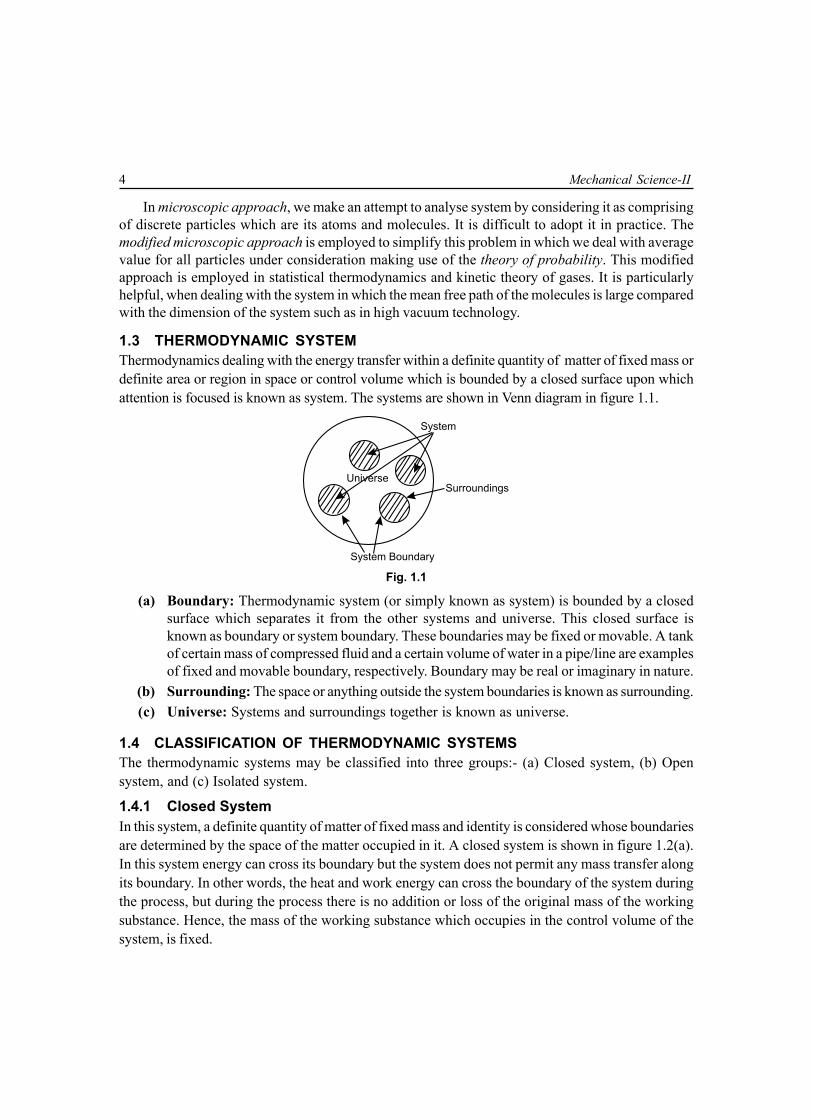
1.3 THERMODYNAMIC SYSTEMThermodynamics dealing with the energy transfer within a definite quantity of matter of fixed mass ordefinite area or region in space or control volume which is bounded by a closed surface upon whichattention is focused is known as system. The systems are shown in Venn diagram in figure 1.1.
Universe
System Boundary
System
Surroundings
Fig. 1.1
(a) Boundary: Thermodynamic system (or simply known as system) is bounded by a closedsurface which separates it from the other systems and universe. This closed surface isknown as boundary or system boundary. These boundaries may be fixed or movable. A tankof certain mass of compressed fluid and a certain volume of water in a pipe/line are examplesof fixed and movable boundary, respectively. Boundary may be real or imaginary in nature.
(b) Surrounding: The space or anything outside the system boundaries is known as surrounding.(c) Universe: Systems and surroundings together is known as universe.
1.4 CLASSIFICATION OF THERMODYNAMIC SYSTEMSThe thermodynamic systems may be classified into three groups:- (a) Closed system, (b) Opensystem, and (c) Isolated system.
1.4.1 Closed SystemIn this system, a definite quantity of matter of fixed mass and identity is considered whose boundariesare determined by the space of the matter occupied in it. A closed system is shown in figure 1.2(a).In this system energy can cross its boundary but the system does not permit any mass transfer alongits boundary. In other words, the heat and work energy can cross the boundary of the system duringthe process, but during the process there is no addition or loss of the original mass of the workingsubstance. Hence, the mass of the working substance which occupies in the control volume of thesystem, is fixed.

Basic Concept and Some Definitions 5
System Boundary
Energy (in)
Closed System(no mass transfer)
Surroundings
Energy (out)
Fig. 1.2 (a)
1.4.2 Open SystemIn this system, both energy (heat and work energy) and mass of the working substance can cross theboundary of the system, during the process. The mass of the working substance within the controlvolume of system may not be constant. It is shown in figure 1.2(b).
System Boundary (real/imaginary)
Energy (in)
Open System
Surroundings
Energy (out)Mass (out)
Mass (in)(both mass andenergy transfer)
Fig. 1.2 (b)
1.4.3 Isolated SystemIn this system, neither energy (heat energy & work energy) nor mass of the working substance cancross the system boundary during the process. During the process ongoing, there is no addition orloss of the energy and mass of working substance which occupy within the control volume. It isshown in figure 1.2.(c).
System Boundary
System Control Volume(no mass/energy transfer)
Surroundings
Fig. 1.2 (c)

6 Mechanical Science-II
1.5 CONTROL MASS AND CONTROL VOLUMEThe region in space of definite quantity of matter of fixed mass and identity is bounded by a closedsurface (boundary), upon which attention is focused for study. Mass inside the system boundary isknown as control mass as shown in figure 1.3(a). In closed system the mass does not cross thesystem boundary, so mass of system is fixed, though its volume can change against a flexible boundary.Therefore fixed mass of closed system is called control mass.
Weights
Control Mass
System Boundary
System(gas)
Pistion
Surroundings
Cylinder
Fig. 1.3 (a)
A control volume is a region in space bounded by a closed envelope on which attention is focusedfor energy analysis. The control volume bounded by a prescribed boundary is known as controlsurface as shown in figure 1.3(b). The control volume need not be fixed in size as well as shape. Itmay not be fixed in position also. However, in most of the applications we deal with control volumewhich are fixed in size and shape as well as fixed in position relative to the observer. An open systemis equivalent in every respect to a control volume.
Heat Q
Mass in
Control Surface
Surroundings
Massout
ControlVolume
Work W
Fig. 1.3 (b)

Basic Concept and Some Definitions 7
1.5.1 Comparison of Properties of a Control Mass and a Control Volume
1.6 THERMODYNAMIC CO-ORDINATESEvery system has certain observable characteristics by which its physical condition may be described.Such characteristics like location, pressure, volume, temperature etc are called properties. Propertiesare the co-ordinates to describe the state of the system. These co-ordinates for locating thermodynamicstate points are defined as the thermodynamic co-ordinates.
1.7 STATE OF A SYSTEMThe state of a system is the configuration of the system at any particular moment which can beidentified by the statement of its properties, such as pressure, volume, temperature etc., so that onestate point may be distinguished from the other states.
1.8 PROPERTIES OF A SYSTEMProperties of a system are thermodynamic co-ordinates of the system which describe its physicalcondition such as location, volume, pressure, temperature etc., So any observable characteristics ofthe system is a property. A sufficient number of independent properties exist to represent the state ofa system. A property of the system depends only upon the state of the system and not upon how thatstate may have been reached. The properties are measurable quantities in terms of numbers andunits of measurements.
Mathematically it can be explained whether any quantity is a property or not as follows.If x and y are two properties of a system, then dx and dy are their exact differentials. In general,
if the differential is of the form of (Mdx + Ndy ), the test for exactness is y x yx
M N ∂ ∂= ∂ ∂
.
1.9 CLASSIFICATION OF PROPERTIES OF A SYSTEMThe thermodynamic properties of a system may be classified into the following two groups:(a) Extensive properties and (b) Intensive properties.
Control mass
1. Refers to a definite quantity of matter onwhich attention is focused.
2. Bounded by a closed boundary which maybe real or imaginary.
3. Matter does not cross the boundaries of acontrol mass.
4. Heat and work interaction are present acrossthe system boundary.
Control volume
1. Refers to a defined region of space on whichattention is focused.
2. Enclosed by a control surface which may bereal or imaginary.
3. Matter continuously flows in and out of thecontrol volume.
4. Control volume can exchange heat and workthrough control surface.

8 Mechanical Science-II
1.9.1 Extensive PropertiesThe properties of a system, whose values for the entire system depending on the mass of the systemare equal to the sum of their values for the individual parts of the system are called extensiveproperties. Total volume, total energy and total mass of the system are extensive properties of thesystem.
The ratio of an extensive property to the mass is called the specific property or the property perunit mass. For example
Specific volume (vs) = 3total volume = m /kgtotal mass m
∀
The ratio of an extensive property to the mole number is called the molar property, like
Molar volume (vm) = 3total volume = m /kgmole number n
∀
1.9.2 Intensive PropertiesThe properties of a system where value do not depend upon the mass of the system are calledintensive properties, such as temperature of the system. It does not depend on the mass of thesystem and whatever remains the mass of the system it is same for the entire system. It is also truefor specific volume, density and pressure of the system.
1.9.3 Difference between Extensive and Intensive Properties with an ExampleThe properties which depend on the mass of a system are called extensive properties, whereas theproperties which do not depend on the mass of a system are called intensive properties. So intensiveproperties are independent of the mass of the properties. At normal temperature and pressure i.e., at0°C and 1 standard atmospheric pressure (at NTP) one mole of a gas occupies a volume of 22.4litres. Consider two systems P and Q such that system P contains 1 mole of oxygen at NTP andsystem Q contains 5 moles of oxygen at NTP. If the volume occupied by the systems P and Q can bemeasured, it will be found that the system Q occupies a volume of 22.4 × 5 = 112.0 litres which isequal to five times the volume occupied by system P. So the volume occupied by a system dependson the mass of the system and hence volume is an extensive thermodynamic property. Measurementof temperature and pressure show that systems P and Q will have the same temperature (0°C) andpressure (one standard atmospheric pressure). Hence, the properties pressure and temperature donot depend on the mass of the system and so are called intensive properties.
1.10 PHASEWhen a quantity of matter is homogeneous throughout in terms of chemical composition and physicalstructure is called a phase. There are three phases, solid, liquid and gas. A system consisting of asingle phase is called a homogeneous system, while a system consisting of more than one phase isknown as a heterogeneous system.
1.11 THERMODYNAMIC EQUILIBRIUMA system is said to be in thermodynamic equilibrium, when no change in any one of the properties dooccur. A system will be in a state of thermodynamic equilibrium, if it satisfies the following three

Basic Concept and Some Definitions 9
requirements of equilibrium (a) Mechanical equilibrium, (b) Chemical equilibrium (c) Thermalequilibrium.
1.11.1 Mechanical EquilibriumThe system is said to be in mechanical equilibrium, when there is no unbalanced force within thesystem.
1.11.2 Chemical EquilibriumThe system is said to be in chemical equilibrium, if there is no chemical reaction and no transfer ofmatter from one part of the system to another.
1.11.3 Thermal EquilibriumWhen a system is in contact with its surroundings across a diathermal wall(wall through which heatcan flow) and if there is no spontaneous change in any of the properties of the system, the system issaid to exist in thermal equilibrium with its surroundings. Also, a system may exist in thermal equilibriumwith another system. Adjacent figure 1.4 illustrates thermal equilibrium between two systems orbetween a system and its surroundings, temperature being one property must be the same.
Adiabatic Wall
Diathermal Wall
System I(x , y , p ,…)1 1 1
System IIx , y , p( ,…)2 2 2
Fig. 1.4
1.12 PATHProperties are the thermodynamic co-ordinates of the state of a system. So the properties are state-variable of the system. When any one or more of the properties of a system change, it is called achange of state. When a system passes through a series of states during a change of state from theinitial state to the final state, it is called the path of the change of state.
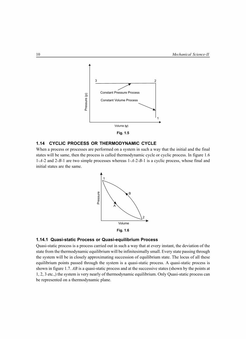
1.13 PROCESSWhen a system passes through a successive states during a change of state from the initial stateto the final state, with a completely specified path for each successive change in states, thechange of state is defined as a process, e.g., a constant volume process, constant pressure process.It is shown in figure 1.5, where 1-2 is a constant volume process and 2-3 is a constant pressureprocess.
A process is designated by the path followed by the system in reaching the final equilibrium statefrom the given initial state.
10 Mechanical Science-II
Volume ( )
A
3 2
1
Constant Pressure Process
Constant Volume Process
Pre
ssure
(p)
Fig. 1.5
1.14 CYCLIC PROCESS OR THERMODYNAMIC CYCLEWhen a process or processes are performed on a system in such a way that the initial and the finalstates will be same, then the process is called thermodynamic cycle or cyclic process. In figure 1.61-A-2 and 2-B-1 are two simple processes whereas 1-A-2-B-1 is a cyclic process, whose final andinitial states are the same.
Volume
A
Pre
ssu
re B
1
2
Fig. 1.6
1.14.1 Quasi-static Process or Quasi-equilibrium ProcessQuasi-static process is a process carried out in such a way that at every instant, the deviation of thestate from the thermodynamic equilibrium will be infinitesimally small. Every state passing throughthe system will be in closely approximating succession of equilibrium state. The locus of all theseequilibrium points passed through the system is a quasi-static process. A quasi-static process isshown in figure 1.7. AB is a quasi-static process and at the successive states (shown by the points at1, 2, 3 etc.,) the system is very nearly of thermodynamic equilibrium. Only Quasi-static process canbe represented on a thermodynamic plane.

Basic Concept and Some Definitions 11
B
A
1
3
2
Thermodynamic Co-ordinate
Ther
mod
ynam
ic C
o-or
dina
te Initial Equilibrium State
Successive Equilibrium States
Final Equilibrium State
X
Y
Fig. 1.7
1.14.2 Non-equilibrium ProcessNon-equilibrium process is a process carried out in such a way that the initial state-point and the finalstate-point are in equilibrium but the intermediate state-points, through which the system is passing,are in non-equilibrium state. Figure 1.8 shows the non-equilibrium process whose initial and finalequilibrium states are joined by a dotted line which has got no-meaning otherwise.
(Initial State)A
B(Final State)
Volume
A
A
A
B
Non-equilibriumProcess
pA
pB
Pre
ssure
Fig. 1.8
1.14.3 Reversible ProcessReversible process is a process carried out in such a way that at every instant, the system deviationis only infinitesimal from the thermodynamic state, and also which can be reversed in direction andthe system retraces the same equilibrium states. Thus in reversible process, the interactions betweenthe system and the surroundings are equal and opposite in direction. The Quasi-static or Quasi-equilibrium process is also known as reversible process. In reversible process the work done couldbe written in the form W = ∫ pd∀ When there is a change in system boundaries.
1.14.4 Irreversible ProcessA process is said to be irreversible, while initial and final states both being in equilibrium, whenreversed, the system and the surroundings do not come to the original initial state and a trace ofhistory of the forward process is left. In actual practice, most of the processes are irreversible, due
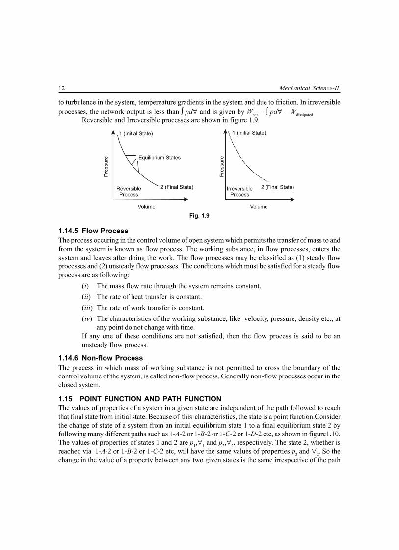
12 Mechanical Science-II
to turbulence in the system, tempereature gradients in the system and due to friction. In irreversibleprocesses, the network output is less than ∫ pd∀ and is given by Wnet = ∫ pd∀ – Wdissipated
Reversible and Irreversible processes are shown in figure 1.9.
Volume Volume
Equilibrium States
2 (Final State)
1 (Initial State)
Pre
ssure
Pre
ssure
1 (Initial State)
2 (Final State)ReversibleProcess
IrreversibleProcess
Fig. 1.9
1.14.5 Flow ProcessThe process occuring in the control volume of open system which permits the transfer of mass to andfrom the system is known as flow process. The working substance, in flow processes, enters thesystem and leaves after doing the work. The flow processes may be classified as (1) steady flowprocesses and (2) unsteady flow processes. The conditions which must be satisfied for a steady flowprocess are as following:
(i) The mass flow rate through the system remains constant.(ii) The rate of heat transfer is constant.(iii) The rate of work transfer is constant.(iv) The characteristics of the working substance, like velocity, pressure, density etc., at
any point do not change with time.If any one of these conditions are not satisfied, then the flow process is said to be anunsteady flow process.
1.14.6 Non-flow ProcessThe process in which mass of working substance is not permitted to cross the boundary of thecontrol volume of the system, is called non-flow process. Generally non-flow processes occur in theclosed system.
1.15 POINT FUNCTION AND PATH FUNCTIONThe values of properties of a system in a given state are independent of the path followed to reachthat final state from initial state. Because of this characteristics, the state is a point function.Considerthe change of state of a system from an initial equilibrium state 1 to a final equilibrium state 2 byfollowing many different paths such as 1-A-2 or 1-B-2 or 1-C-2 or 1-D-2 etc, as shown in figure1.10.The values of properties of states 1 and 2 are p1,∀1 and p2,∀2. respectively. The state 2, whether isreached via 1-A-2 or 1-B-2 or 1-C-2 etc, will have the same values of properties p2 and ∀2. So thechange in the value of a property between any two given states is the same irrespective of the path

Basic Concept and Some Definitions 13
between the two states. Thus in the present illustration, the differences of values of properties, i.e.,2
2 11= – dp p p∫ and
2
1∫ d∀ = ∀2 – ∀1 are always the same between the states 1 and 2 whether the
path followed is 1-A-2 or 1-B-2 or any other one. It is also true for any quantity being a pointfunction, the change of which is independent of path.
The path followed to reach the final state from a initial state is called the process. The quantity,the value of which depends on the path followed during a change of state is a path function. Forexample, in the above figure, the areas under 1-A-2, 1-B-2 etc, are different i.e.,
22 11–dA A A≠∫
A
1
A
2
AA
B
D
E
C1
2
p1
p2
p
Fig. 1.10
Where initial value A1 and the final value A2 have no meaning. The integral value of such quantitiesas
21 2 121
= ordA A A∫The area for process between state 1 and 2 can only be determined, when the path followed isknown.
1.16 UNITThe primary quantities are measured in terms of the basic or fundamental units and the secondaryquantities are measured in terms of derived units.
1.16.1 Fundamental UnitsFundamentals units are the basic unit normally which are unit of mass (M), unit of length (L) and unitof time(T), but in the International System of units, there are seven fundamental units and twosupplementary units, which cover the entire field of science and engineering. These units are shownin the Table 1.1.

14 Mechanical Science-II
Table: 1.1. Fundamental and Supplementary UnitsFundamental Unit:
Sl.No. Physical Quantity Unit Symbol
1. Mass (M) kilogram kg
2. Length (L) metre m
3. Time (t) second s
4. Temperature (T) kelvin K
5. Electric current (I) ampere A
6. Luminous intensity (Iv) candela Cd
7. Amount of substance (n) mole mole
Supplementary Unit:
1. Plane angle (α, β, θ, φ) radian rad
2. Solid angle (Ω) steradian Sr
1.16.2 Derived UnitsSome units expressed in terms of other basic units, which are derived from fundamental units areknown as derived units. The derived units, which will be commonly used in this book, are given inthe following table.
Table: 1.2. Derived Units
Sl.No. Physical Quantity Unit Symbol
1. Area m2 A
2. Angular velocity rad/s ω
3. Angular acceleration rad/s2 α
4. Linear velocity m/s V
5. Linear acceleration m/s2 a
6. Mass density kg/m3 ρ
7. Force, weight N F, W
8. Work, energy, enthalpy J W, E, H
9. Pressure N/m2 p
10. Power Watt P
11. Absolute or dynamic viscosity N-s/m2 µ
12. Kinematic viscosity m2/s υ
13. Characteristic gas constant J/kg.K R
Contd..

Basic Concept and Some Definitions 15
14. Universal gas constant J/kgmol.K Rm
15. Frequency Hz, 1Hz = 1cps f
16. Thermal conductivity W/mK k
17. Specific heat J/kg.K C
18. Molar mass or molecular mass kg/mol M
19. Sp. weight or wt. density kgf/m3 wS
20. Sp. volume m3/kg vS
21. Volume m3 ∀
1.17 SYSTEMS OF UNITSThere are only four systems of units, which are commonly used and universally recognized. Theseare known as:
(1) C.G.S systems (2) F.P.S systems (3) M.K.S systems (4) S.I (System Internationale orInternational system of units).The internationally accepted prefixes in S.I to express large and smallquantities are given below in the table.
Table: 1.3. Prefix Factors
Factor of Multiplication Prefix Symbol
1012 tera T
109 giga G
106 mega M
103 kilo k
122 hecto h
101 deca da
10–1 deci d
10–2 centi c
10–3 milli m
10–6 micro m
10–9 nano n
10–12 pico p
1.18 MASS (M)Mass is the amount of matter contained in a given body and it does not vary with the change in itsposition on the earth’s surface.

16 Mechanical Science-II
1.19 WEIGHT (W)The weight is the amount of force of attraction, which the earth exerts on a given body. The weightof the body will vary with its position on the earth’s surface, because force of attraction vary withvariation of distance between the two bodies.
1.20 FORCE (F)Force may be defined as an agent which produces or tends to produce, destroy or tends to destroythe motion. According to Newton’s Second Law of Motion, the applied force or impressed force isdirectly proportional to the rate of change of momentum
Hence, F ∝ mv – mut
⇒ F ∝ m v – ut
⇒ F ∝ m a∴ F = k .m. aWhere k is the constant of proportionality. If the unit of force adopted so that it produces unit
acceleration to a body of unit mass, then∴ 1 = k.1.1⇒ k = 1⇒ F = maor, Force = mass × × × × × accelerationIn S.I the unit is newton(N) and 1N = 1 kg m/s2.There are two types of units of force, absolute and gravitational. When a body of mass 1 kg is
moving with an acceleration of 1 m/s2, the force acting on the body is 1 newton(N). This is theabsolute unit of force.
When a body of mass 1 kg is attracted towards the earth with an acceleration of 9.81m/s2, theforce acting on the body is 1 kilogram-force, briefly written as ‘kgf’ or kg-wt. The unit of force in kgfis called gravitational or engineers, unit of force or metric unit of force. From the Newton’s SecondLaw of Motion
F = k.m.a = m. c
gg = weight
Where a = g (acceleration due to gravity), and
k =1 ,cg
while
gC = 9.80665 kg 2ms
≈ 9.81 kg . 2ms
. 1
kgf

Basic Concept and Some Definitions 17
and 1 kgf =21 kg ×9.81 m/s
cg = weight
If, local value of g is numerically the same as gC then the weight of 1 kg becomes equal to 1 kgf.The gravitational unit of force is ‘g’ times greater than the absolute unit of force or S.I unit of
force, as1 kgf = 1 kg × 9.81 m/s2 = 9.81 m/s2 = 9.81 N
1.21 SPECIFIC WEIGHT (wS)It is the weight per unit volume. It is also known as the weight density. It may be expressed inkgf/m3, in MKS system of unit and newton/m3 in S.I.
Specific weight (wS) =W∀ =
mg∀ = ρ.g
1.22 SPECIFIC VOLUME (vS)It is defined as the volume per unit mass. It may be expressed in m3/kg.
Specific volume (vS) = m∀
= 1ρ
1.23 PRESSUREPressure is the normal force exerted by a system against unit area of the boundary surface. The unitof pressure depends on the units of force and area. In S.I, the practical units of pressure are N/mm2,N/m2, kN/m2, MN/m2 etc.
A bigger unit of pressure known as bar, such that1 bar = 1 × 10⁵ N/m2 = 0.1 × 10⁶ N/m2 = 0.1 MN/m2
Other practical units of pressure are Pascal (Pa), kilopascal (kPa) & mega Pascal (MPa), such that1 Pa = 1N/m2
1 kPa = 1 kN/m2 = 103 N/m2
1 MPa = 1 × 10⁶ N/m2 = 103 kPa = 1 N/ mm2
1.24 ABSOLUTE, GAUGE AND VACUUM PRESSUREThe pressure is measured in two different systems. In one system, it is measured above the absolutezero or complete vacuum, and is defined as absolute pressure. In other system, pressure is measuredabove the atmospheric pressure, and is defined as gauge pressure. So
(a) Absolute pressure: It is defined as the pressure which is measured with reference toabsolute zero pressure.
(b) Gauge pressure: It is defined as the pressure which is measured with reference toatmospheric pressure. It is measured with the help of a pressure measuring instrument. It isa pressure above the atmospheric pressure.

18 Mechanical Science-II
(c) Vacuum pressure: It is the pressure below the atmospheric pressure. Sometimes it iscalled as negative gauge pressure.The relationship between the absolute pressure, gaugepressure and vacuum pressure are shown in figure 1.11.
Positive GaugePressure
Absolu
teP
ressure
Above
Atm
ospheric
p > 1 atm
p > 1 atm
p < 1 atm
p = 0
Negative Gauge Pressureor Vacuum Pressure
LocalA
tmospheric
Pre
ssure
Absolu
teP
ressure
Belo
w
Pre
ssure
Atm
ospheric
Zero Pressure
Perfect Vacuum
Fig. 1.11
Mathematically(i) Absolute pressure = atmospheric pressure + gauge pressure
pabs = patm + pgauge
(ii) Vacuum pressure = atmospheric pressure − absolute pressure= patm − pabs
1.25 PRESSURE MEASUREMENT BY MANOMETERA manometer is normally used to measure pressure. In manometer the pressure is determined accordingto the hydrostatic formula. The manometric liquid may be mercury, water, alcohol, etc.A U-tube manometer is shown in figure 1.12. Since manometric fluid is in equilibrium, the pressurealong a horizontal line AB is the same for either limb of manometer, then
p + 1 1ρ
c
g zg
= patm + 2 2ρ
c
g zg
Where p is the absolute pressure in the bulb, patm is the atmospheric pressure exerted on the freesurface of liquid and ρ1 and ρ2 are the densities of the liquid in the bulb and manometer respectively.
If ρ1 is small as compared to ρ2 i.e., ρ1<< ρ2, 1 1ρ . 0c
g zz
≈
then p – patm = 2 2ρ .
c
g zg = pgauge

Basic Concept and Some Definitions 19
BA
p1
Z1
p
z2
p2
Open to Atmosphere (p )atm
ManometricLiquid
Fig. 1.12
Table: 1.4. Conversion Factor for Pressure
Bar dyne/cm2 kgf/cm2 N/m2 mm Hg at mm H2O atmor ata or Pa 21°C or torr at 21°C
Bar 1 106 1.01972 105 750.062 10197.2 0.986923
dyne/cm2 10–6 1 1.01972 0.1 750.062 10197.2 0.986923× 10–6 × 10–6 × 10–6 × 10–6
kgf/cm2 0.980665 0.980665 1 0.980665 735.559 10000 0.967838or ata × 106
N/m2 10–5 10 10.1972 1 750.062 10197.2 0.986923or Pa × 10–6 ×10–5 ×10–5 ×10⁻⁵
mm of Hg 1.333233 1.333233 1.3595 1.333233 1 13.5951 1.31578at 21°C × 10–3 × 103 × 10–3 × 10⁻³
mm of H2O 98.0665 98.0665 10–4 9.80665 0.073556 1 96.7838at 21°C × 10–6 × 10⁻⁶
atm 1.01325 1.01325 1.03323 1.01325 760 103523 1× 106 × 105

20 Mechanical Science-II
1.26 NORMAL TEMPERATURE AND PRESSURE (N.T.P)Normal temperature is at 0°C or 273 K temperature and normal pressure is 760 mm of Hg. Normaltemperature and pressure are briefly written as N.T.P.
1.27 STANDARD TEMPERATURE AND PRESSURE (S.T.P)The temperature and pressure of any gas, under standard atmospheric condition, is taken as 15°C(288K) and 760 mm of Hg respectively.
1.28 ENERGYThe simplest definition of energy is the capacity for doing work. In other words, a system is said toposses energy when it is capable of doing work. The energy can be classified as (i) Stored energyand (ii) Transit energy.
The stored energy is a thermodynamic property as it depends on the point, not upon the path. Thestored energy is the energy which is contained within the system boundaries. Examples of storedenergy are (i) potential energy (ii) kinetic energy (iii) internal energy etc.
The transit energy is in transition and crosses the system boundaries. Examples of transit energyare (i) heat (ii) work (iii) electrical energy etc. The transit energy is not a thermodynamic propertyas it depends upon the path.
1.29 TYPES OF STORED ENERGYThe potential energy, kinetic energy or an internal energy are the different types of stored energy andare discussed in detail, as follows:
1.29.1 Potential EnergyThe energy possessed by a body, or a system for doing work, by virtue of its location or configurationis called potential energy. If a body of mass m is at an elevation of z above the datum plane, thepotential energy(P.E) possessed by the body is given by
PE = mgz = W.zwhere g is the acceleration due to gravity.
1.29.2 Kinetic EnergyThe energy possessed by a body, or a system for doing work, by virtue of its motion is called kineticenergy. If a body of mass of m moves with a velocity v the kinetic energy(KE) possessed by the bodyis given by
KE =12
mv2
The sum of the potential energy and kinetic energy of a body is called the Mechanical energy ofthe body.
1.29.3 Internal EnergyThis energy is possessed by a body, or a system due to its molecular arrangement and motion of themolecules. It is usually represented by U and the change in internal energy (dU). It depends upon thechange in temperature of the system.
∴ change of internal energy dU = Cv (T2 − T1)Where Cv is specific heat at constant volume &

Basic Concept and Some Definitions 21
T1 and T2 are the temperature at state points∴ The total energy of the system (E) is equal to the sum of the P.E, K.E and internal energy.
∴∴∴∴∴ E = P.E + K.E + U[any other form of the energy such as chemical, electrical energy etc. are neglected]
Again E = mgz + 12
mv2 + U = ME + U
while Mechanical energy (M.E) = P.E. + K.E = mgz + 12
mv2
For unit mass, total energy
e = gz +12
v2 + u
When the system is stationary and the effect of gravity is neglected, then,∴ E = U and e = u
1.30 LAW OF CONSERVATION OF ENERGYThe law of Conservation of Energy states that The energy can neither be created nor destroyed,though it can be transformed from one form to any other form, in which the energy can exist.
1.31 POWERPower may be defined as the rate of doing work or work done per unit time or rate of energy transferor storage. Mathematically,
Power = w ork donetim e taken
=energy storage or transfer
time takenThe unit of power in S.I is watt (W)
1 W = 1 N.m/s = 1 J/sA bigger unit of power called kilowatt (kW) or megawatt (MW)
1 kW = 1000 W and 1 MW = 106 W = 1000 kWIf T is the torque transmitted expressed in N.m or J and the angular speed is ω in rad/s, then
Power (P) = T × ω
= T × 2π60
N watt, ω = 2πN/60
N is speed in r.p.m
Hence, Efficiency (η) =power outputpower input

22 Mechanical Science-II
Multiple Choice Questions
1. In a closed thermodynamic system there is(a) only mass transfer (b) only energy transfer(c) both mass and energy transfer (d) none of the above
2. In flow system there is(a) no mass transfer across the boundaries (b) neither mass nor energy transfer(c) both mass and energy transfer (d) none of the above
3. In an isolated system there is(a) no mass transfer (b) no energy transfer(c) neither mass nor energy transfer (d) both mass and energy transfer
4. Which of the following are the properties of the system?(a) ∫pd∀ (b) ∫∀dp(c) ∫ (pd∀ + ∀dp) (d) ∫ dT/T = CV .dp/T
5. Which of the following is an intensive property?(a) volume (b) temperature(c) density (d) entropy
6. Which of the following is an extensive property?(a) pressure (b) temperature(c) density (d) volume
7. 1 torr is equivalent to(a) 1 kgf/cm2 (b) 1 N/m2
(c) 1 atm (d) 1mm of Hg
8. The expression ∫pd∀ may be applied for obtaining work of(a) non-flow reversible process (b) steady flow reversible process(c) steady flow non-reversible process (d) steady flow adiabatic reversible process
9. Each of heat and work is(a) point function (b) path function(c) property of a system (d) state description of a system
10. The property which depends only on temperature is(a) internal energy (b) enthalpy(c) entropy (d) none of above
11. A definite area or a space where some thermodynamic process takes place is known as(a) thermodynamic cycle (b) thermodynamic process(c) thermodynamic system (d) thermodynamic law
12. When either of mass or energy is not allowed to cross the boundary of a system; it is then called(a) closed system (b) open system(c) isolated system (d) none of these

Basic Concept and Some Definitions 23
13. Which of the following is not a thermodynamic property?(a) pressure (b) temperature(c) heat (d) specific volume
14. When a process or processes are performed on a system in such a way that the final state is identicalwith the initial state, it is then known as(a) thermodynamic cycle(b) thermodynamic property(c) thermodynamic process(d) zeroth law of thermodynamics
15. Atmospheric pressure is equal to(a) 1.013 bar (b) 101.3 kN/m2
(c) 760 mm of Hg (d) all of the above
16. 1 mm of H2O is equal to(a) 100 ××××× 10–6 bar (b) 0.001 kgf/ cm2
(c) 9.80665 Pa (d) 0.077 mm Hg
17. –40°C is equal to(a) –40°F (b) 230K(c) 400°R (d) –72°F
18. A centrifugal fan forms(a) closed system (b) open system(c) isolated system (d) none of the above
19. Which of the following statement is correct?(a) isolated system uninfluenced by surrounding is called universe.(b) system and surrounding combine to constitute universe whether there are interaction with each
other or not.(c) system which only interacts with surrounding is part of the universe.(d) system and surrounding put together form universe only if there is interaction between them.
20. Thermodynamic system may be defined as a quantity of matter upon which attention is focussed forstudy if(a) it is only bounded by real surface(b) the boundary surfaces are constant in shape and volume.(c) it is not bounded by imaginary surface(d) it is bounded by either real surfaces or imaginary surfaces irrespective of shape or volume.
Answers
1. (b) 2. (c) 3. (c) 4. (c) 5. (b) 6. (d) 7. (d) 8. (a) 9. (b) 10. (a)11. (c) 12. (c) 13. (c) 14. (a) 15. (d) 16. (c) 17. (a) 18. (b) 19. (b) 20. (d)

24 Mechanical Science-II
NUMERICAL EXAMPLES
EXAMPLE 1If pvS = RT (where vS = specific volume, p = pressure, R = a constant and T = temperature) determine
whether the following quantities (i) sv dpdT – T T
∫ and (ii) s
S
pdvdT + T v
∫ can be used as properties.
SOLUTION
Each of the differential is of the form (Mdx + Ndy).
Therefore, apply the test yx
M Ny x
∂ ∂ = ∂ ∂[Condition of exact differential equation]
(i) Thus, for sv dpdT –T T
we can write the condition
1
T
Tp
∂
∂ =
– s
p
vTT
∂ ∂
or,
1
T
Tp
∂
∂ =
–
p
RpT
∂ ∂
as s
s
pv = RTv R=T p
∴
or, 0 = 0
Thus, – sv dpdTT T
is an exact differential equation and may be written as sv dpdT –T T
= dS where S is a point
function and hence a property.
(ii) For S
S
pdvdTt v
+
, we have
1
sT
Tv
∂
∂ =
s
s
v
pvT
∂ ∂
or,
1
sT
Tv
∂
∂ =
2
s
s
v
RTvT
∂
∂

Basic Concept and Some Definitions 25
or, 0 = 2( )
svs
R TTv
∂ ∂ s
s
RTA pv
=
or, 0 = 2s
Rv
But 2s
Rv
≠ 0. So, it is not an exact differential.
Therefore, S
S
pdvdTT v
+
is not a point function. So, it is not a property.
EXAMPLE 2Explain if the following can be used a properties (i) ∫ pd∀ (ii) ∫ ∀dp (iii) ∫ (pd∀ + ∀dp).
SOLUTION
(i) ∫ pd∀ is an expression where p is function of ∀ and they are connected by a line path on p and ∀ plane. Thevalue ∫ pd∀ depends on the area under the line path on p and ∀ planes. Thus it is not an exact differential,it is a path function, not a point function. So it is not a property.
(ii) ∫ ∀dp is such an expression where ∀ is a function of p and they are connected by a line path on p and ∀planes. So it is a path function not a point function. Thus, it is not an exact differential and thus not aproperty.
(iii) ∫ pd∀ + ∫∀dp = ∫ d(p.∀) = p.∀
So, it is an exact differential and hence it is a property.
EXAMPLE 3A manometer contains a fluid having a density of 1200 kg/m3. The difference in height of two
columns is 400 mm. What pressure difference is indicated thus? What would be the height difference, if thesame pressure difference is to be measured by a mercury manometer having mass density of mercury13600 kg/m3.SOLUTION
The pressure difference indicated p1 = ρgh = 1200 × 9.81 × 400/1000 = 4708.8 Pa = 4.7088 kPa
Again p1 = 4708.8⇒ 4708.8 = ρgghg = 13600 × 9.81 × hg
⇒ hg = 4708.8
13600×9.81 = 53.3 mm
So, length of mercury column 53.3 mm.
EXAMPLE 4The pressure of steam inside a boiler, measured by pressure gauge is 1 N/mm2. The barometeric
pressure of the atmosphere is 765 mm of mercury. Determine the absolute pressure of steam in N/m2, kPa, barand N/mm2.

26 Mechanical Science-II
SOLUTION
Gauge pressure = 1 N/mm2 = 1 × 10⁶ N/m2
Atmospheric pressure = 765 mm of Hg
We know that atmospheric pressure
= 765 mm of Hg
= 765 × 133.3 = 0.102 × 10⁶ N/m2 (∵ 1 mm of Hg = 133.3 N/m2)
∴ Absolute pressure of steam
= atmospheric pressure + gauge pressure
= 0.102 ×10⁶ + 1 × 106 = 1.102 × 10⁶ N/m2
= 1102 kPa (∵ 1 kPa = 103 N/m2)
= 11.02 bar (∵ 1 bar = 105 N/m2)
= 1.102 N/mm2 (∵ 1 N/mm2 = 106 N/m2)
EXAMPLE 5In a condenser of a steam power plant, the vacuum pressure is recorded as 700 mm of mercury. If
the barometer reading is 760 mm of mercury, determine the absolute pressure in the condenser in N/m2, kPa, barand N/mm2.SOLUTION
Vacuum pressure = 700 mm of Hg
Barometer reading = 760 mm of Hg
We know that absolute pressure
= atmospheric pressure – vacuum pressure
= barometer pressure – vacuum pressure
= 760 − 700 = 60 mm of Hg
= 60 × 133.3 = 7998 N/m2
= 7.998 kPa
= 0.07998 bar
= 0.007998 N/mm2
EXAMPLE 6Compute the quantity of heat required to raise the temperature of a steel forging of mass 180 kg
from 300 K to 1265 K. The specific heat of steel = 0.49 kJ/ kg K.SOLUTION
Given: m = 180 kg, T1 = 300 K, T2 = 1265 K, C = 0.49 kJ/kg K
We know that quantity of heat required

Basic Concept and Some Definitions 27
= mass × specific heat × rise in temperature
= mC ( T2 − T1)
= 180 × 0.49 ( 1265 − 300)
= 85113 kJ
EXAMPLE 7The forced draught fan supplies air to furnace of the boiler at draught of 30 mm of water. Determine
the absolute pressure of air supply if the barometer reads 760 mm mercury, in kgf/cm2, bar and kPa.SOLUTION
Since it is a forced draught, the absolute pressure is above atmospheric pressure.
Absolute pressure = atmospheric pressure + gauge pressure
= barometer reading + forced draught reading
We know, 1 mm of water 1
13.595= 0.073556 mm Hg
∴ 30 mm of water = 30 × 0.073556 Hg
= 2.20668 mm Hg
Thus, absolute pressure = 760 + 2.20668 = 762.20668 mm Hg
=762.20668735.559
kgf/cm2
= 1.03623 kgf/ cm2
= 1.03623 × 0.981 = 1.01654 bar
=5
31.01654 10
10×
= 101.654 kPa
EXAMPLE 8The pressure in a gas pipe is measured by a mercury manometer as shown in the figure. One leg of
manometer is open to atmosphere. If the difference in the height of mercury column in the two legs is 450 mm,compute the gas pressure in the pipe in kPa, bar and in atm. The barometeric reading is 755 mm Hg. The localacceleration due to gravity is 9.81 m/sec2 and the mass density of mercurry is 13595 kg/m3.SOLUTION
Referring figure,
The pressure of gas at plane a – a is given by
p = pa + ρgh [ Neglecting the density of gas as compared to that of mercury]
And pa = ρgh0
where ρ is density of mercury
28 Mechanical Science-II
h0 is the barometeric height
h is the height of mercury column
g is the local acceleration due to gravity
So, p = ρgh0 + ρgh = ρg (h0 + h)
= 13595 kg/m3 × 9.81 m/sec2 × (0.755 + 0.450) m
= 160.707 × 10³ N/m2
= 160.707 kPa
= 1.60707 bar [∵ 1 bar = 100 kPa]
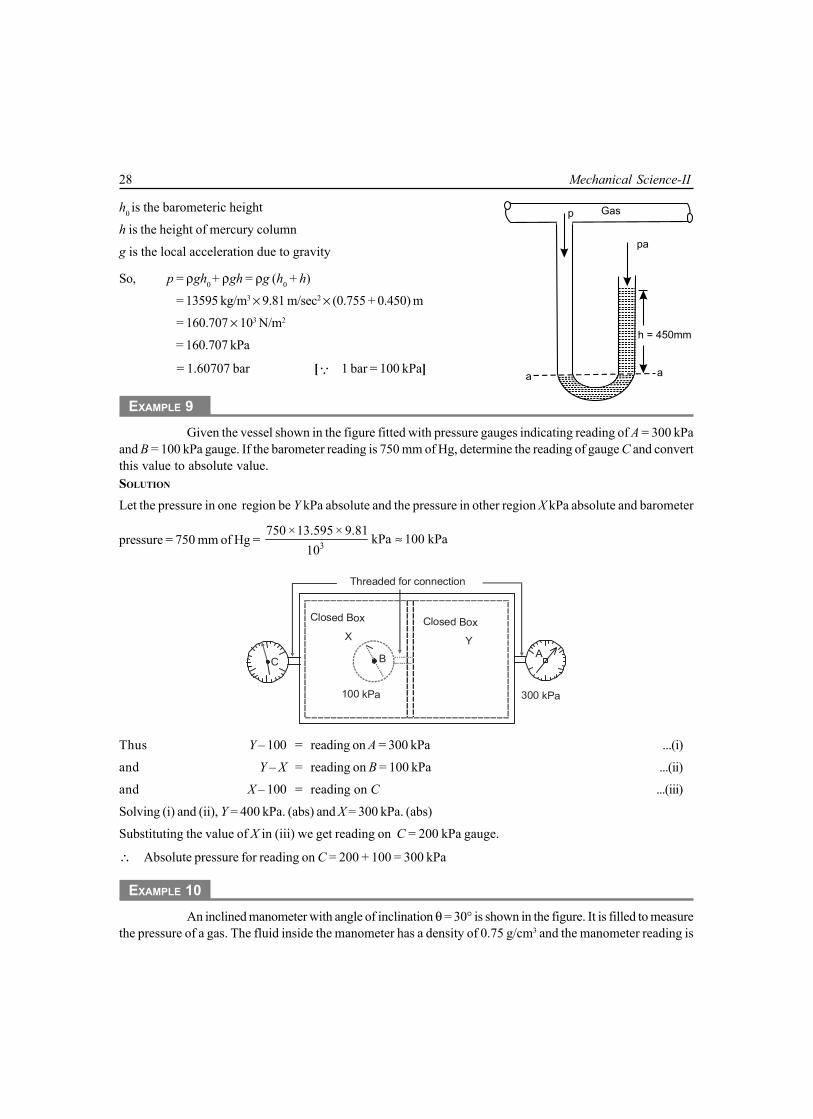
EXAMPLE 9Given the vessel shown in the figure fitted with pressure gauges indicating reading of A = 300 kPa
and B = 100 kPa gauge. If the barometer reading is 750 mm of Hg, determine the reading of gauge C and convertthis value to absolute value.SOLUTION
Let the pressure in one region be Y kPa absolute and the pressure in other region X kPa absolute and barometer
pressure = 750 mm of Hg = 3750 ×13.595 × 9.81 kPa 100 kPa
10≈
A
300 kPa
Closed Box
Y
Closed Box
X
B
100 kPa
Threaded for connection
C
Thus Y – 100 = reading on A = 300 kPa ...(i)
and Y – X = reading on B = 100 kPa ...(ii)
and X – 100 = reading on C ...(iii)
Solving (i) and (ii), Y = 400 kPa. (abs) and X = 300 kPa. (abs)
Substituting the value of X in (iii) we get reading on C = 200 kPa gauge.
∴ Absolute pressure for reading on C = 200 + 100 = 300 kPa
EXAMPLE 10An inclined manometer with angle of inclination θ = 30° is shown in the figure. It is filled to measure
the pressure of a gas. The fluid inside the manometer has a density of 0.75 g/cm3 and the manometer reading is
a a
p Gas
h = 450mm
pa

Basic Concept and Some Definitions 29
labelled on the diagram as x = 0.3 m. If the atmospheric pressure is 101.25 kPa and the acceleration due to gravityis g = 9.7 m/sec2, determine the absolute pressure of the gas in kPa.SOLUTION
For inclined manometer, verticle liquid columnh = 0.3 sin 30° = 0.15 m
The gauge pressure is given bypgauge = ρgh
=( )
–3
3–2
0.75 ×10 9.81 0.1510
× ×
= 1103.625 Pa= 1.103625 kPa
Thus absolute pressure is given bypabs = pgauge + patm
= 1.103625 + 101.25 = 102.353625 kPa
EXAMPLE 11Convert (a) 3 kgf/cm2 absolute to kgf/cm2 gauge, (b) 45 cm vacuum to cm of Hg absolute and to
kgf/cm2 absolute (ata). (c) 0.5 kgf/cm2 absolute i.e., 0.5 ata to cm of Hg vacuum, (d) 25 cm of Hg gauge to cm ofHg absolute and to atmosphere, (e) 1ata to kPa. Barometer may be assumed to be 760 mm of Hg.SOLUTION
Here, 1 kgf/cm2 = 735.559 mm of Hg = 735.6 mm of HgSo, 760 mm Hg = 1.03323 kgf/cm2 = 1.033 kgf/cm2
(a) Absolute pressure − Barometer pressure = Gauge pressureor, 3 – 1.033 = Gauge pressure∴ Gauge pressure = 1.967 kgf/cm2
(b) Barometer pressure − Absolute pressure = Vacuum pressureor, 76 cm of Hg − Absolute pressure = 45 cm of Hg∴ Absolute pressure = (76 − 45) cm Hgor, = 31 cm of Hg absolute(c) Barometer pressure − Absolute pressure = Vacuum pressureor, 1.033 kgf/cm2 − 0.5 kgf/cm2 = Vacuum pressureor, 0.533 kgf/cm2 = Vacuum pressure∴ Vacuum pressure = 0.533 kgf/cm2
= 0.533 × 73.56 cm of Hg vacuum
= 39.20748 cm of Hg vacuum.
θ = 30°
..........
..........
..........
..........
..........
..........
..........
..........
..........
..........
..........
..........
..........
..........
..........
..........
..........
..........
..........
..........
..........
..........
..........
..........
..........
..........
..........
..........
..........
..........
..........
..........
..........
..........
..........
..........
..........
..........
..........
..........
..........
..........
..........
..........
..........
..........
..........
..........
..........
..........
..........
..........
..........
..........
..........
..........
..........
..........
..........
..........
..........
..........
..........
..........
..........
..........
..........
..........
..........
..........
..........
..........
..........
..........
..........
..........
..........
..........
..........
..........
................
................
................
................
....
....
....
....
....
....
....
....
....
..............................................
..........................................
..........................................
..........................................
h
x = 0.3mGAS

30 Mechanical Science-II
(d) Abs pressure − Barometer pressure = Gauge pressure
Abs pressure − 76 cm of Hg = 25 cm of Hg
Abs pressure = 101 cm of Hg absolute
= 101/76 atm = 1.33 atm
(e) 1 ata = 1 kgf/cm2
= 0.981 × 10² kPa
= 98.1 kPa.
EXERCISE
1. Explain the terms (a) thermodynamic state (b) thermodynamic process (c) thermodynamic cycle.
2. What do you understand by macroscopic and microscopic view points of thermodynamics?
3. What is thermodynamic system? Explain its different types.
4. What do you understand by property of a system? Distinguish between extensive and intensiveproperties of a system with the help of an example.
5. What is a thermodynamic process and a cyclic process?
6. Explain the non-equilibrium and quasi-static process. Is the quasi-static process a reversible process?
7. Distinguish between gauge pressure and absolute pressure. How the gauge pressure is convertedinto absolute pressure?
8. What do you understand by N.T.P and S.T.P? What are their values?
9. Compare the control volume and control mass.
10. Define energy. What is stored energy and transit energy. Discuss the types of stored energy.
11. Distinguish between absolute pressure and gauge pressure. How is one related to the other in case ofvacuum.
12. Define the following(a) Point function and Path function(b) Specific weight(c) Specific volume(d) Pressure(e) Temperature(f) Density(g) Flow process & Non-flow process.
13. Mercury of density 13.59508 g/cm3 is used as monometer fluid. What gauge pressure in bar is exertedby a column of mercury of 760 mm ?
Ans. [ 1.01325 bar]
14. Which of the following can be used as properties of the system

Basic Concept and Some Definitions 31
(a) dT dp+T T
∀ ∫
(b)dT dp–T
∀ ∀∫ .
15. A piston has area of 5 cm2. What mass must the piston have if it exerts a pressure of 50 kPa aboveatmospheric pressure on the gas enclosed in the cylinder.
16. A pressure gauge reads 2.4 bar and the barometer reads 75 cm of Hg. Calculate the absolute pressurein bar and in the standard atmosphere.
17. A manometer has a liquid of density 800 kg/cm2, the difference in level of the two legs is 300 mm.Determine the pressure difference read by it in kgf/m2; bar; kPa.
18. The pressure of steam inside a boiler is recorded by a pressure gauge as 1.2 N/mm2. If the barometerreads the atmospheric pressure as 770 mm of Hg, find the absolute pressure of steam inside the boilerin N/m2, kPa and bar.
Ans. [ 1.3026 × 10⁶ N/m2, 1302.6 kPa, 13.026 bar]
19. In a condenser, the vacuum is found to be 145 mm of mercury and the barometer reads 735 mm ofmercury. Find the absolute pressure in a condenser in N/m2, kPa and N/mm2.
Ans. [ 78647 N/m2, 78.647 kPa, 0.078647 N/mm2]

This pageintentionally left
blank

2.1 TEMPERATUREThe temperature is an intensive thermodynamic property of the system, whose value for the entiresystem is not equal to the sum of the temperature of its individual parts. It determines the degree ofhotness or the level of heat intensity of a body or a system. A body is said to be at a high temperatureor hot, if it shows high level of heat intensity in it and a body is said to be at a low temperature or cold,if it shows a low level of heat intensity.
2.2 ZEROTH LAW OF THERMODYNAMICSThis law states,“When each of two systems are in thermal equilibrium with a third system, thenthe two systems are also in thermal equilibrium with one another.”
Let a body X is in thermal equilibrium with a body Y, and also separately with a body Z, thenfollowing above law, Y and Z will be mutually in thermal equilibrium with each other. A system is saidto be in thermal equilibrium, when there is no temperature difference between the parts of thesystem or between the system and the surroundings. Zeroth law provides the basis of temperaturemeasurement.
2.3 MEASUREMENT OF TEMPERATUREThe temperature of a system is a property that determines whether or not a system is in thermalequilibrium with other system. The temperature of a system or body is measured with the help of aninstrument known as Thermometer. A thermometer may be in the form of a glass tube containingmercury in its stem. Or any physical body with at least one measurable property that changes as itstemperature changes can be used as a thermometer, for example, a length of a column of mercury inan evacuated capillary tube. The height of mercury column in a thermometer, therefore, becomes athermometric property. There are other methods of temperature measurement which utilize variousother properties of a materials, which are functions of temperature as thermometric properties. Theparticular substance that exhibits changes in thermometric properties is called thermodynamicsubstance. Commonly used properties of materials employed in temperature-sensing devices orthermometers are given below and the names of the corresponding thermometric properties employed.
2CHAPTER
ZEROTH LAW AND TEMPERATURE
34 Mechanical Science-II
Table: 2.1. Types of Thermometer
Sl.No. Thermometer Thermometric Property Symbol
1. Mercury alcohol in glass thermometer Length L
2. Constant volume gas thermometer Pressure p
3. Constant pressure gas thermometer Volume ∀
4. Electric resistance Resistance R
5. Thermocouple Electromotive force E
6. Radiation (pyrometer) Intensity of radiation I or J
7. Optical pyrometer Monochromatic radiation
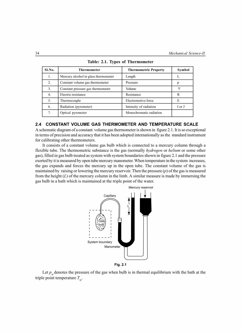
2.4 CONSTANT VOLUME GAS THERMOMETER AND TEMPERATURE SCALEA schematic diagram of a constant volume gas thermometer is shown in figure 2.1. It is so exceptionalin terms of precision and accuracy that it has been adopted internationally as the standard instrumentfor calibrating other thermometers.
It consists of a constant volume gas bulb which is connected to a mercury column through aflexible tube. The thermometric substance is the gas (normally hydrogen or helium or some othergas), filled in gas bulb treated as system with system boundaries shown in figure 2.1 and the pressureexerted by it is measured by open tube mercury manometer. When temperature in the system increases,the gas expands and forces the mercury up in the open tube. The constant volume of the gas ismaintained by raising or lowering the mercury reservoir. Then the pressure (p) of the gas is measuredfrom the height (L) of the mercury column in the limb. A similar measure is made by immersing thegas bulb in a bath which is maintained at the triple point of the water.
Mercury reservoir
Capillary
System boundary
Manometer
Gasbulb
L
Fig. 2.1
Let ptp denotes the pressure of the gas when bulb is in thermal equilibrium with the bath at thetriple point temperature Ttp.

Zeroth Law and Temperature 35
For an ideal gas at constant volume
We have,tp
TT
=tp
pp
∴ T =tp
pp
× T (2.1)
The triple point temperature of water has been assigned a value of 273.16 K.Therefore, equation (2.1) can be rewritten as
T = 273.16tp
pp
(2.2)
The measured pressure (p) at the system temperature (T) as well as the pressure (ptp) at thetriple point temperature change depending on the quantity of gas in the gas bulb. A plot of T calculatedfrom equation (2.2) as a function of ptp appears as shown in Fig. 2.2. It shows that the value of T andptp→ 0 is identical for different gases. This behaviour can be expected because all gases behave likeideal gases as p → 0. Hence to obtain the correct temperature one should ensure that ptp is as lowas possible. Therefore, to obtain the actual temperature of the system, equation (2.2) is modified as
T =0,
273.16 Lttpp p tp
pp→
Measured data extrapolated tozero pressure
pptp
O2
N2
He
H2
ptp
Fig. 2.2
Therefore, in the limit when the pressure tends to zero, the same value is obtained for each gas.Thus, the temperature scale is defined as
T =0,
273.16 Lttpp p tp
pp→
(2.3)
pT = 273.16 Lt
ptp

36 Mechanical Science-II
The temperature value which has been measured does not depend on the properties of thesubstance is called Thermodynamics Temperature Scale.
2.4.1 International Practical Temperature Scale (IPTS-68)In view of the practical difficulties associated with the use of ideal gas thermometer, the InternationalCommittee on Weight and Measures has adopted the International Practical Temperature Scalein 1968 based on a number of easily reproducible fixed points. The standard fixed point which iseasily reproducible by international agreement is triple point of water, the state of equilibrium betweensteam, ice and liquid water. The temperature at this point is defined as 273.16 Kelvin, abbreviatedas 273.16 K, as a matter of convenience. This makes the temperature interval from icepoint = 273.16 K to steam point = 373.16 K equal to 100 K, at pressure of 1atm.
2.4.2 Celsius or Centigrade ScaleThe ice point of water on this scale is marked as zero, and the boiling point of water, at a pressure of1atm is 100. The space between these two points has 100 equal divisions and each division representsone degree Celsius (written as °C); then
t = T − 273.16°C (2.4)
Thus, the Celsius temperature (ts) at which steam condenses at a pressure of 1 atm
ts = TS− 273.16°C = 373.16°C − 273.16°C = 100.0°C
2.4.3 Electrical Resistance ThermometerIn the resistance thermometer the change in resistance of a metal wire due to its change in temperatureis the thermodynamic property. The wire, frequently, may be incorporated in a Wheatstone Bridgecircuit. In a restricted range, the following quadratic equation is often used
Rt = R0 ( 1 + at + bt2 + ct3 + …) (2.5)Where R0 is the resistance of the platinum wire when it is surrounded by melting ice, Rt is the
resistance at temperature t and a and b are constants.The triple point represents an equilibrium state between solid, liquid and vapour phases of substance.
Normal boiling point is the temperature at which the substance boils at standard atmospheric pressureof 760 mm Hg. Normal freezing point is the solidification or melting point temperature of the substanceat standard atmospheric pressure.
Table: 2.2. Fixed Points of the IPTS – 68
Sl.No. Equilibrium State Assigned value of temperature
T(K) t(°C)
1. Triple point of hydrogen 13.81 –259.34
2. Boiling point of hydrogen at 33.306 kPa 17.042 –266.108
3. Normal boiling point of hydrogen 20.28 –252.87
4. Normal boiling point of neon 27.102 –246.048
5. Triple point of oxygen 54.361 –218.789Contd...

Zeroth Law and Temperature 37
6. Normal boiling point of Oxygen 90.188 –182.962
7. Triple point of Water 273.16 0.01
8. Normal boiling point of Water 373.15 100.1
9. Normal freezing point of Antimony 630.74 357.59(Antimony point)
10. Normal freezing point of Zinc (Zinc point) 692.73 419.58
11. Normal freezing point of Silver (Silver point) 1235.08 961.93
12. Normal freezing point of Gold (Gold point) 1337.58 1064.43
The whole temperature scale may be divided into four ranges, based on the available method ofmeasurement. The equation for interpolation for each range are as follows:
(i) From – 259.34°C (Triple point of Hydrogen) to 0°C: A platinum resistance thermometerof a standard design is used. A polynomial equation of the following form is deployed.
Rt = R0 ( 1 + at + bt2 + ct3) (2.6)
Here R0 is the resistance at the ice point is fitted between resistance of the wire (Rt) and thetemperature (t).
(ii) From 0°C to 357.59°C (Antimony point): It is also based on platinum resistancethermometer. The diameter of the platinum wire must lie between 0.05 and 0.2 mm andgoverning equation is
Rt = R0 ( 1 + at + bt2 ) (2.7)
(iii) From 357.59°C to 1064.43°C(Gold point): It is based on standard platinum versus platinumthermocouple. A three term equation, as following, is used.
E = a + bt + ct2 (2.8)
Here E is the EMF of the thermocouple.(iv) Above 1064.43°C: The temperature is calculated from Planck’s equation for black body
radiation.
2.5 HEAT AND HEAT TRANSFERThe heat is defined as the form of energy which is transferred, without transfer of mass, across aboundary by virtue of a temperature difference between the system and the surroundings. It is aform of transit energy which can be identified only when it crosses the boundary of a system.
The temperature difference is the ‘potential’ or ‘force’ and heat transfer is the ‘flux’. The heatcan be transferred in three distinct ways, i.e., conduction, convection and radiation. The processof heat transfer between two bodies in direct contact is called conduction. The heat may be transferredbetween two bodies separated by empty space or gases by electromagnetic waves and the processis known as radiation. A third method of heat transfer is convection through fluid in motion.
The heat always flows from higher temperature to lower temperature without external energy.So, heat is transferred across a boundary from a system at a higher temperature to a system at lowertemperature by virtue of the temperature difference. The heat is a form of transit energy, so it is not

38 Mechanical Science-II
a thermodynamic property. It is not a point function, it is a path function. Conventionally when heatflowing into a system, it is considered positive and heat flowing out of a system, it is considerednegative, shown in Fig.2.3.
System Boundary
Surroundings
Q (out)
(–ve)
System
Q (in)
(+Ve)
Fig. 2.3
2.6 SPECIFIC HEATThe specific heat of a substance is defined as the amount of heat required to raise the temperatureof unit mass of any substance by one degree. It is generally denoted by C and its unit in S.I is takenas kJ/kg.K. Heat required to raise the temperature of m kg mass of a substance from an initialtemperature of T1 to a final temperature of T2, then
Heat required Q = mC (T2 – T1 ) kJ (2.4)where T1 and T2 may be either in 0°C or in K and C is specific heat in kJ/kg.K.The solids and liquids do not change or change very negligibly in volume on heating, therefore
they have only one specific heat. But gases have the following two specific heats depending upon theprocess adopted for heating the gas.
(i) Specific heat at constant pressure Cpand(ii) Specific heat at constant volume CvIt is noted that Cp is always greater than Cv. Relation between two specific heats is: Cp – Cv= R,
where R is known as characteristic gas constant and its unit is J/kg K or kJ/kg.K. Value of gasconstant (R) is different for different gases. For air it is taken as 287J/kg K or 0.278 kJ/kg.K. in S.I.
Ratio of Cp and Cv is, p
v
CC
= γ where γ is adiabatic index. For air γ = 1.4 [For details see chapter
on properties of perfect gas]
2.7 THERMAL OR HEAT CAPACITY OF A SUBSTANCEIt is defined as the amount of heat required to raise the temperature of whole mass of a substancethrough one degree. Mathematically,

Zeroth Law and Temperature 39
Thermal or heat capacity of a substance = mC kJWhere m = mass of the substance in kg, and C = specific heat of the substance in kJ/kg.K.
2.8 WATER EQUIVALENT OF A SUBSTANCEIt may be defined as the quantity of water requires to raise unit temperature by the same quantity ofheat which requires the substance to raise its temperature through one degree. Mathematically,
Water equivalent of a substance = mC kgWhere m = mass of the substance in kg, and
C = specific heat of the substance in kJ/kg.K.The thermal capacity and water equivalent of a substance are equal in numerical value, but in
different units.
2.9 MECHANICAL EQUIVALENT OF HEATHeat and work are mutually convertible which was established by Joule. He established, experimentally,that certain amount of work is required to produce unit amount of heat. The ratio between work (W)and heat (H) i.e., is denoted by J (named after Joule) and is known as Joule’s equivalent ormechanical equivalent of heat.
2.10 WORKIn mechanics, work is the effect of force. The work is said to be done by a force when the force actsupon a body and body moves in the direction of applied force. The magnitude of mechanical work isthe product of the force and the distance moved parallel to the direction of applied force. Mathematically
2
1
= W dW FdS= ∫
where F is applied force, and dS is the differential displacement parallel to direction of applied force.The unit of work depends on the unit of force and unit of distance moved. In S.I, unit of force is
newton and unit of distance is meter, so the practical unit work is N-m. It is known also as joule(briefly written as J). So, 1 N-m = 1 J.
In thermodynamics, work may be defined as the energy in transition between the system andsurrounding. So, the work may be defined as follows:
(a) According to Obert: Work is defined as the energy transferred (without the transferof mass) across the boundary of a system because of an intensive property differenceother than temperature that exists between the system and surrounding.The pressure difference, i.e., the intensive property difference (between the system andsurrounding) at the surface of the system gives rise to a force and the action of this forceover a distance is called mechanical work.Electrical work is also the same case. In this case the intensive property difference is theelectrical potential difference between the system and surrounding. And the resulting energytransfer across the system and boundary is known as electrical work.

40 Mechanical Science-II
(b) According to Keenan: Work is said to be done by a system during a given operationif the sole effect of the system on things external to the system (surroundings) can bereduced to the raising of a weight.The weight may not be raised actually but the net effect external to the system should be theraising of a weight.
Switch ()
Resistance
SystemBoundarySystem
Fig. 2.4 (a)
To give example of this, consider a system consisting of a battery as shown in Fig.2.4(a).The terminals connected to a resistance through a switch is on for a certain period of time,then the current will flow through the battery and resistance. As a result the resistance willbe warmer. This clearly shows that the system (battery) has interaction with the surroundings.In other words, energy transfer(electrical energy) has taken place between the system andthe surroundings because of potential difference(not the temperature). According to thedefinition of work, by laws of mechanics, if there is no force which moves through adistance, then no work is done by the system. However, according to the thermodynamicdefinition, the work is done by system because the resistance can be replaced by a idealmotor(100% efficient) driving a winding drum, thereby raising an weight, as shown inFig. 2.4(b). Thus, the sole effect external to the system (surrounding) has been reduced tothe raising of an weight. Hence, thermodynamic work is done by the system.
System
Fig. 2.4 (b)

Zeroth Law and Temperature 41
Also, it is relevant to mention that work is manifested at the system boundary only during anyinteraction between the system and surroundings. Before interaction no work is present. Only worktransfer takes place.
2.11 SIGN CONVENTION OF WORKIn thermodynamics, by convention, work done by the system is taken to be positive i.e., when workleaves from the system. The work done on the system is taken to be negative i.e., if work enters intothe system from surrounding, as shown in Fig.2.5. In any process when the system does positivework, its surroundings do an equal amount of negative work. Thus, in any process algebraic sum ofwork done by the system and its surrounding is zero. Mathematically,
Wsystem + (– Wsurrounding) = 0 (2.9)
System
W (out)
W (in)
(– ve)
Surroundings
System Boundary
(+ ve)
Fig. 2.5
2.12 WORK DONE DURING A QUASI-STATIC OR QUASI-EQUILIBRIUM PROCESSFrom the concept of mechanics, the differential work done (dW) is given by
dW = F.dS (2.10)where F is the applied force and dS is the differential displacement.
Consider a certain amount of gas contained in a cylinder-piston assembly as shown in theFig.2.6(a) in a schematic representation of work by a gas. The system, enclosed by the dotted line,constitute the gas contained in the cylinder and Fig. 2.6(b) is representation of work done on a p–∀
diagram. The shaded area represents the work done 2
1
pd∀∫ by the gas. In a differential time dt, let
the piston of cross-sectional area A moves a differential distance dL while the motion of piston isopposed by an external pressure (p – dp) where dp→0. Then, the differential work done by the gasis given by
dW = F.dS= (pA) dL [∵ F = p × A]= p.AdL

42 Mechanical Science-II
Cross Sectional Area
p – dp
p p
Gas
dL
Fig. 2.6 (a)
= p. d∀ [∵ d∀ = A dL]
∴ W =2
1
.p d∀∫ (2.11)
It may be noted that the external pressure (p – dp) is always infinitesimally smaller than the gaspressure inside the system. Hence, the expansion process can be reversed at any time by increasingthe external pressure infinitesimally more than the gas pressure. That is, if the external pressure is(p + dp), the gas undergoes a compression process.
1
2
A B
A2A1
dA
p2
p1
Pre
ssure
Volume
Fig. 2.6 (b)
During the process, the expansion or compression of the gas creating a force on the movingboundary are balanced and hence the process is reversible. Being a reversible one, it must be a

Zeroth Law and Temperature 43
Quasi-Static or Quasi-Equilibrium Process, because ‘a reversible process is a quasi-static process,but a quasi-static process need not be a reversible process’.
2.13 WORK AND HEAT TRANSFER — A PATH FUNCTIONConsider that a system, from an initial equilibrium state 1 reaches to a final equilibrium state 2 by tworeversible process 1-A-2 and 1-B-2 as shown in Fig.2.7(a). When the system changes from its initialstate 1 to final state 2, the quantity of work or heat transfer will depend upon the intermediate stagesthrough which the system passes, i.e., its path.
1
2
A B
A
1
A
B
Volume
Pre
ssure
p1
p2
A
2
Fig. 2.7 (a)
Figure 2.7(a) shows two different reversible paths 1-A-2 and 1-B-2 connecting the given initial
and final states of system. Since 2
1
.p d∀∫ represents the area under the curve, the work done during
path 1-A-2 is different from the work done during the path 1-B-2. In other words, the work donedepends on the path, followed in going from one state to another i.e., by a system.
Hence, it is not possible to evaluate the work done purely from a knowledge of its initial and finalstates of a system. The work done by a system is a path function and hence it is not a property of asystem. Work is an interaction, that is energy transfer, between a system and its surroundings.Hence work is energy in transit. Mathematically work is an inexact differential and written as δW.On integrating for path 1-A-2,
2
1,A∫ δW = [ ]2
1,AW = (W1-2)A (2.12)
It should be noted that in the case of inexact differentials such as work, 2
1∫ δW ≠ W2 − W1
because work is not a point function. We never speak of work W1 in the system in state 1 or work W2in state 2. In contrast to this, there is only work, either Win or Wout in transition, which manifests itself

44 Mechanical Science-II
at the system boundary during a process, and can only be found by integration of (pd∀) along thepath followed in the quasi-equilibrium process.
1
2
A B
A
B
Entropy
Tem
pera
ture
T2
S1 S2
T1
Fig. 2.7 (b)
Like work, heat transfer during from its initial state point 1 to final state point 2 will depend on theintermediate state through which the system passes, i.e., its path. In other words, heat is a path functionand is an inexact differential and written as δQ. On intergrating for the path 1-A-2 in Fig. 2.7(b)
2
1,A
Qδ∫ = [Q]21,A = (Q1–2)A= (1Q2)A (2.13)
It may be noted that in the case of inexact differentials such as heat, 2
1,A∫ δQ ≠ Q2− Q1, because
heat is not a point function and it would be more appropriate to write 2
1,A∫ δQ = (Q1-2)A. It can be
written as the integral of the product of intensive property (T) and differential change of an extensive
property, say entropy (S), i.e. 2
1,A∫ T δS. The T-S diagram is shown in the figure.
2.14 COMPARISON OF HEAT AND WORKSimilarities between heat and work are follows :
(i) Heat and Work are neither thermodynamic properties, nor point functions. The systemitself does not posses heat and work. When a system undergoes a change, heat transferor work done may occur. They are both transient phenomena.
(ii) The heat and work are boundary phenomena. They are observed at the boundary ofthe system.

Zeroth Law and Temperature 45
(iii) Heat and work are both transit energy crossing the boundary of the system.(iv) The heat and work both are path functions and hence are inexact differentials. They
are written as δQ and δW.(v) The area under the pressure-volume (i.e., p-∀) diagram represents the work done during
the process and is given by ∫ pd∀. Similarly the area under the temperature-entropy i.e.,(T-S) diagram represents the heat transfer during the process and is given by ∫ TdS.
(vi) Work is written by the integral of the product of the intensive property(p) and differentialchange of the extensive property (∀).
Heat transfer can also be written as the integral of product of the intensive property (T) and thedifferential change of an extensive property, entropy(S).
2.15 EXAMPLE OF WORK2.15.1 Paddle Wheel WorkThis is also known as Stirring Work where ∫ pd∀ = 0, but work is done.
The paddle wheel work is an illustration of shaft-work. Paddle wheel work process is a processinvolving friction in which the volume of the system does not change at all, and still work is done onthe system.
Representation of the process is provided by a system in which a paddle wheel turns a fixedmass of fluid as shown in Fig.2.8. Consider that in the system weight is lowered, paddle wheel runs.The work is transferred across the system boundary in the fluid system. The volume of the systemremains constant and the work, ∫ pd∀ = 0.
Closed System
Closed System
W (in)
Weight = mg
Shaft
Paddle
WindingDrum
Fig. 2.8
If m is the mass of the weight lowered through a distance dz and T is the torque transmitted bythe shaft in rotating through an angle dθ, the differential work transfer to the fluid is given by
δW = mgdz = Tdθ

46 Mechanical Science-II
Work transfer (W) =2
1∫ δW
=2
1∫ mg dz =
2
1∫ T.dθ (2.14)
Thus, ∫pd∀ does not represent work for this case, although work has been done on the system.So work may be done on a closed system even though there is no volume change.
2.15.2 Extension of Solid RodConsider an elastic rod of length L and cross-sectional area A, which is fixed at one end as shown inFig.2.9 as the system. The solid rod is fixed at x = 0, and a tensile force equal to F is applied at theother end of the rod.
Area = A
x 2x1x
F
L
Fig. 2.9
Thus, F = σAwhere s is normal stress acting at the end of the rod. The rod elongates a distance dx due to elasticproperty. The work done due to elongation dx is given by
δW = − σAdxThe negative sign shows that work is done on the rod when dx is positive. The work done for
change of length from x1 to x2 is given by,
W = − 2
1
x
x∫ (σAdx) (2.15)
2.15.3 Stretching of a Liquid Film (Surface Tension)Suppose a liquid film is held between a wire from one side of which can be moved with the help ofa sliding wire as shown in Fig.2.10 as a system. The interfacial tension or surface tension which isthe force per unit length normal to a line on the surface is given by τ.Thus, force is given by, F = 2Lτ;when the factor 2 indicates two film surfaces act at the wire length L.

Zeroth Law and Temperature 47
dx
Rigid Wire FrameSurface of Film
MovableWire
F
x
Fig. 2.10
The work for displacement dx is given by,δW = −2Lτ . dx
Negative sign shows that work is done on the system when dx is positive. The surface in contactwith wire is dA = 2Ldx
Thus,δW = −τdA
∴ W = −2
1
A
A∫ δW
= −2
1
A
A∫ τdA = −τ (A2 − A1) (2.16)
2.15.4 Free Expansion ProcessThe free expansion, or unresisted expansion, process is an irreversible non-flow adiabatic process inwhich the volume of a closed system increases, and still no work at all is done. So, here ∫ pd∀ is finitebut work done is zero. Representation of this unresisted expansion process is shown in Fig. 2.11(a)& (b). A free expansion occurs when a fluid is allowed to expand suddenly into a vacuum chamberthrough an orifice of large dimensions.
System Boundary
Membrane
Fluid
(p , A , T )1 1 1
A B
Vacuum
p = 0ext
Fig. 2.11(a)

48 Mechanical Science-II
Consider two chambers A and B separated by a membrane. The chamber A contains fluid havingvolume ∀1 pressure p1 and temperature T1 and the chamber B is completely evacuated, pressure i.e.,pext = 0. The fluid is in state 1 in chamber A. Let the membrane gets ruptured. The fluid then fills boththe chambers and reaches state 2. Initial pressure p1 of the fluid dropped to p2 in the final state andvolume ∀1 reaches to volume ∀2 in the final state. Both the chambers are completely insulated sothat heat transfer is zero.
Let us first consider the fluid and vacuum together as the system shown in Fig.2.11(a), so as nowork crosses the system boundary. Next we consider only the fluid as the system as in the figure2.11(b). We observe that the system boundary moves and volume of the system change from ∀1 to∀2
. But it is not quasi-equilibrium process and pext = 0 . Hence, ∫pext.d∀ is also zero and therefore, nowork is done in the process. Free expansion process is thus an example of an expansion process inwhich ∫pd∀ is finite, but still W1-2 = 0. Hence, it is adiabatic process where Q1-2 = 0 and U1-2 = 0
(p , A , T )1 1 1
Membrane Ruptured
Fluid
A B
System Boundary
W = 0
Q = 0
Fig. 2.11 (b)
2.15.5 Shaft WorkWhen a shaft within a system is rotated, by a motor, there is work transfer into the system asshown in the Fig.2.8. This is so since the shaft can rotate a drum which in turn can raise on weight.If T is the torque applied to shaft running at N r.p.m, (angular velocity ω) then the rate of workdone would be
W = T.ω = 2π
60NT
(2.17)
Paddle wheel work is an example of negative shaft-work.
2.15.6 Electrical WorkElectrical work done by the flow of a current through electrolytic cell or a conductor or a resistor,etc., is given by
1W2= –2
1∫ E.I.dt
where E is the potential difference, I is the current and dt is the time change.

Zeroth Law and Temperature 49
So, power can be written by
P = −Wt
δδ
= − E.I (2.18)
2.15.7 Flow WorkThe flow work is the work required to move a fluid into or out of a system. To calculate the workrequired, consider an element of fluid of mass dm and volume d∀. It is required to push this fluid intothe control volume of an open system through a passage against an existing pressure p as shown inFig.2.12 (a).Cross-sectional area of the passage is A. The fluid behind this element of fluid acts as apiston, and pushes the fluid into the control volume. Consider the imaginary piston is placed behindthis elemental fluid, as shown in figure 2.12 (b). The distance moved by piston is dx, when the fluidwith volume d∀ has been pushed into the control volume.
Specific volume of the fluid vS = ,ddm
∀
(b)
Pushing of Fluid byan Imaginary Piston
Imaginary Piston
(a)
ControlVolume
Flowing Fluid
Flow
dx
Area A
dmdv
dmdv
dmdv
Control Surface
p
dx
Fig. 2.12 (a & b)
Force F = p.A and dx =dA∀
Now the required flow work isδW = force × distance moved
= F × dx
= p . A dA∀
= p. d∀
Work done per unit mass of the fluid flow is
Wflow =W
dmδ

50 Mechanical Science-II
=.p ddm
∀
= p. ddm
∀
= p. vs (2.19)
So the magnitude of the flow work per unit mass of fluid flow is simply the product of the twoproperties of the fluid, i.e., pressure and specific volume.
2.15.8 Non-flow WorkConsider a closed system process, say a cylinder and piston arrangement as shown in the Fig.2.6(b)from 1 to 2. The non-flow work done by the system in the process per unit mass of the substance is
Wnonflow =2
1∫ pdvS (2.20)
and represented by the area 1-2-b-a-1, this is pdvs work.
2.16 WORK IN NON-FLOW PROCESS VERSUS FLOW PROCESSA process undergone by a closed system of fixed mass is referred to as a non-flow process. Achange of state of a substance taking place while flowing through a control volume in an open systemis referred to as a flow process.
The work done in a non-flow process in closed system is called non-flow work. The work donein a flow process in an open system is equal to the non-flow work plus the flow work.
i.e., wflow = ∫ pdvs + p.vs
Multiple Choice Questions
1. Temperature is a(a) property (b) non property
2. Thermometers used in thermodynamic applications are(a) constant volume gas thermometer(b) constant pressure gas thermometer(c) pyrometer(d) all of these
3. When heat flows into a system, conventionally it is considered(a) negative (b) positive
4. The unit of specific heat of any substance is (a) J/kg (b) Jkg(c) kg/J (d) J/kgK
5. The ratio of Cp and Cy of any substance is called(a) adiabatic constant (b) isothermal index(c) pressure index (d) isobaric constant

Zeroth Law and Temperature 51
6. Heat and work are(a) exact integrals (b) inexact integrals
7. Temperature is an(a) exact integral (b) inexact integral
8. The amount of work done in free expansion process is(a) non zero (b) zero(c) unity (d) none of these
9. In constant volume gas thermometer temperature is measured in terms of(a) height of mercury column (b) diameter of mercury column(c) volume of mercury column (b) none of these
10. The S.I. unit for water equivalent of a substance is(a) kg (b) J/kgK(c) K (d) none of these
11. The S.I. unit for heat capacity of a substance is (a) kg (b) J/kgK(c) K (d) J
12. The generally accepted values of adiabatic constant for air is (a) 1.04 (b) 0.104(c) 10.4 (d) 1.4
13. The S.I. unit for adiabatic constant is(a) J/kg (b) kg/J(c) J/kgK (d) unitless, pure number
14. The specific heat for any gaseous substance in constant volume process is generally symbolised by (a) Cv (b) Cp(c) Cr (d) none of these
15. The specific heat for any gaseous substance in constant pressure process is generally symbolised by(a) Cv (b) Cp(c) Cr (d) none of these
Answers1. (a) 2. (d) 3. (b) 4. (d) 5. (a) 6. (b) 7. (a) 8. (b) 9. (a) 10. (a)
11. (d) 12. (d) 13. (d) 14. (a) 15. (b)
NUMERICAL EXAMPLES
EXAMPLE 1
Over a specified temperature range, the electrical resistance thermometer holds the relationshipas: Rt = R0 [ 1 + α (t – t0)], where R0 is resistance in ohm, measured at reference temperature t0 in 0°C and α ismaterial constant with unit of (°C)–1. The test result are: Rt = 51.39 ohm at t = 0°C, Rt = 51.72 ohm at t = 91°C.Determine the reading of the resistance for 70°C, 50°C and 100°C on this thermometer.

52 Mechanical Science-II
SOLUTION
Given t0 = 0°C, t = 0°C, Rt = 51.39We have Rt = R0 [ 1 + α (t − t0)]So, 51.39 = R0 (1 + 0)∴ R0 = 51.39Again, t0 = 0°C , t = 91.0°C, Rt = 51.72∴ Rt = R0 [ 1 + α (t − t0)]
51.72 = 51.39 [ 1 + α (91 − 0)]= 51.39 + α × 51.39 × 91
Therefore, α =51.72 – 51.39
51.39×91 = 7.05657 × 10⁻⁵/°C
Thus, R70° = R0 [1 + α (t − t0)]= 51.39 [1 + 7.05657 × 10−5 × 70] = 51.644 ohm
R50° = 51.39 [1 + 7.05657 × 10−5 × 50] = 51.57 ohm
R100° = 51.39 [1 + 7.05657 × 10−5 × 100] = 51.75 ohm
EXAMPLE 2The resistance of a platinum wire is found to be 11 ohms at the ice point, 15.247 ohms at steam
point, and 28.887 ohms at the Zinc point. Find the constant a and b in the equation. Rt = R0 (1 + at + bt2).
SOLUTION
Here, R0 = 11ohm, Rsteam = 15.247ohm, Rz = 28.887ohm and Zinc point = 419.58°CFollowing the relation, Rt = R0 (1 + at + bt2)
15.247 = 11 (1+ a × 0.01 + b × 0.012)or, 1.3861 = 1 + 0.01a + 0.0001bor, 0.3861 = 0.01a + 0.0001bor, 38.61 = a + 0.01b (i)And 28.887 = 11 [ 1 + a × 419.58 + b (419.58)2]or, 2.6261 = 1 + 419.58 a + 176047.3764 bor, 1.6261 = 419.58 a + 176047.3764 b (ii)
Solving equations (i) and (ii), we obtain the constants asa = 38.6109, b = − 0.092
EXAMPLE 3The temperature t on a thermometric scale is defined in terms of a property K by the relation
t = a ln K + b where a and b are constants. The values of K are found to be 1.83 and 6.78 at the ice point and thesteam point, the temperatures of which are assigned the numbers 0 and 100 respectively. Determine thetemperature corresponding to a reading of K equal to 2.42 on the thermometer.

Zeroth Law and Temperature 53
SOLUTION
From the relation t = a ln K + b, we have
0 = a ln 1.83 + b (i)
and 100 = a ln 6.78 + b (ii)
Solving above equations, a = 78.68951, and b = − 47.5533282
Hence, relation is t = 78.68951 ln K − 47.5533282
For K = 42, we find t = 78.68951 ln 2.42 − 47.5533282
= 21.989 °C
EXAMPLE 4A constant volume gas thermometer containing nitrogen is brought into contact with a system of
unknown temperature and then into contact with a system maintained at the triple point of water. The mercurycolumn attached to the device has reading of 59.2 and 2.28 cm respectively for the two systems. If the barometricpressure is 960 m bar (96.0 kPa), what is the unknown temperature in Kelvin, if g = 9.806 m/ sec2. Specific gravityof mercury may be taken as 13.6.SOLUTION
We know T = 273.16tp
pp
where T is the unknown temperature, p is the gauge pressure at unknown temperature, ptp is the gauge pressureat the triple point of water.
So, pgauge at unknown temperature
= 3 59.213.6 ×10 × 9.807 ×100
N/m2
= 78.95 kPa = 789.5 m bar
∴ pabs = (789.5 + 960) m bar
= 1749.5 m bar = 174.95 kPa = p
Now, pgauge at triple point temperature
= 33
2.2813.6 ×10 × 9.807 ×10
N/m2
= 3.0406 kPa = 30.406 m bar
∴ pabs = (30.406 + 960) m bar = 990.406 m bar
= 99.0406 kPa = ptp
Hence, the unknown temperature T = 273.16 174.9599.0406
= 482.52 K

54 Mechanical Science-II
EXAMPLE 5A constant volume gas thermometer immersed in boiling water of t1 = 100°C reads z1 = 30.0 cm
of Hg. Later the thermometer is immersed in a radiator fluid at temperature of 150°C. That time, barometricpressure is 76.0 cm Hg. Determine the height z2 of the mercury column, in cm. Assume the gas in thethermometer as perfect gas.SOLUTION
For perfect gas we can write
1 1
1
pT∀
= 2 2
2
pT∀
= constant (i)
At constant volume above relation reduce to
1
1
pT
= 2
2
pT
(ii)
So, 0 2
2
z + zt
= 0 1
1
z + zt (iii)
Here, T1 = 100 + 273 = 373 K, z1 = 30 cmT2 = 150 + 273 = 423 K, z0 = 76 cm
Applying equation (iii), we get z2 = 44.21 cm
EXAMPLE 6A soap film is suspended on a 5 cm × 5 cm wire frame ABCD as shown in figure. The movable wire
BC is displaced by 1 cm to B′C′ by an applied force while the surface tension of soap film remains constant at25 × 10–5 N/cm2. Estimate the work done in stretching the film in N.m.SOLUTION
The film is a closed system with moving boundary. Work done, on both side of the film.
W =2
1
A
A∫ τdA = −
2
1
x
x∫ τ.2L dx
= −τ2L 2
1
x
x∫ dx = −τ2L (x2 – x1)
= −25 × 10–5 × 2 × 5 × 1
= −250 × 10–5 N.cm = −2.5 × 10⁻⁵ N.m
The (–) ve sign indicates that work is done on the film.
EXAMPLE 7A gas in the cylinder and piston arrangement comprises the system is shown in Fig.2.6(a).
It expands from 1.5 m3 to 2 m3 while receiving 200 kJ of work from a paddle wheel. The pressure on the gasremains constant at 600 kPa. Determine the net work done by the system.
A B
C D
5 cm
C
B5 cm
1 cm

Zeroth Law and Temperature 55
SOLUTION
The work done by the piston is given by ∫ pd∀ and this is the work done by the system
Wgas =2
1.5∫ pd∀
= p 2
1.5∫ d∀ [pressure is constant]
= [ ]22 1 1.5–p ∀ ∀
= 6 × 10⁵ (2 − 1.5) N.m or J= 3 × 10⁵ J
The gas also receives 200 kJ from the paddle wheel and this is work done on the system.Thus, the net work done by the system is,
Wnet = 3 × 10⁵ − 200 × 103
= 1 × 10⁵ N.m = 100 kJ
EXAMPLE 8A gas is at a pressure of 3 bar in cylinder attached with frictionless movable piston shown in
Fig.2.6(a). The spring force exerted through the piston is proportional to the volume of gas. Also additionalatmospheric pressure of 1 bar acts on the spring side of piston. Determine the work done by gas in expansionfrom 0.1 m3 to 0.5 m3.SOLUTION
The pressure exerted by the springpS = gas pressure − atmospheric pressure
= 3 – 1 = 2 bar = 2 × 10⁵ N/m2
Thus, the spring force is given byFS = pS × A = (2 × 10⁵ × A) N
where A is cross-sectional area of piston in m2. This force gives spring displacement of x1 = volume 0.1=area A
Thus, spring constant is given by kS = 52×10 ×
0.1A
A
= 20 × 105 A2 N/m
Similarly we can write x2 =0.5A
The work done against the spring
WS =2
1
5 220×10 ×x
x
A xdx∫

56 Mechanical Science-II
= 20 × 105 A2
2
1
2
2
x
x
x
= 10 × 105 A2 [ x22 − x1
2]
= 10 × 105 A22
2 20.5 0.1–A A
= 2.4 × 10⁵ N.m.Work done against atmosphere Watm = 1 × 10⁵ (0.5 – 0.1) = 0.4 × 10⁵ N.m
Thus, total work done by the gas W = WS + Watm
= 2.4 × 10⁵ + 0.4 × 105 = 2.8 × 10⁵ N.m or J.
EXAMPLE 9For a system whose mass is 4.5 kg undergoes a process and the temperature changes from 50°C to
100°C. Assume that the specific heat of the system is a function of temperature only. Calculate the heat transfer
during the process for the following relationship Cn = 200.3
150T
+ + kJ/ kg K.
SOLUTION
Here T1 = 273 + 50 = 323 K, T2 = 273 + 100 = 373 K, m = 4.5 kg.
and Cn = 0.3 + 20+ 150T
∴ Q1–2 =373
323nmC dT∫
=373
323
204.5 0.3 ++150
dTT
∫
=373 373
323 323
4.5 0.3 +/20 + 150/20
dTdTT
∫ ∫
= [ ]373
373323
323
10.3 + ln (0.05 + 75)0.05
T T
= [ ]14.5 0.3× 50 + ln (18.65 + 75) – ln (16.15 + 75)0.05
=1 93.654.5 15 + ln
0.05 91.15
= 69.935 kJ

Zeroth Law and Temperature 57
EXERCISE
1. Define temperature. Name the different temperature scale in common use. Establish relation betweenCelsius and Fahrenheit scale?
2. What is absolute temperature ?
3. What do you understand by N.T.P and S.T.P? What are their values?
4. Distinguish between gauge pressure, absolute pressure and atmospheric pressure. What are theirrelation.
5. Define energy. What is stored energy and transit energy? Discuss the types of stored energy.
6. Define thermodynamic work. Show that both heat and work are a path function not a point function.
7. Work done is given by W = ∫pd∀, Is there be any situation where d∀ = 0 and yet dW ≠ 0?
8. Which of the following characteristics are true for work? (a) It is a path functions (b) It is not aproperty of a system. (c) Its differential is not exact. (d) It is not stored in a system (e) It is energy intransit. (f) It can be indentified only during the course of interaction.
9. Which of the characteristics given in question no. 8 are true for heat.
10. State the Zeorth Law of Thermodynamics. How is mercury in thermometer able to find the temperatureof a body using the Zeroth Law of Thermodynamics.
11. Power transmission through a rotating shaft is a common engineering practice. Derive a relation todetermine the power transmitted through a rotating shaft.
Ans. [P = Tω]
12. An aqueous soap solution is maintained in the form of thin film, on a wire frame as shown in Fig 2.10.If the surface tension of the liquid is 72.75 mN/m. Calculate the work done when the movable wire isdisplaced by 1 cm in the direction indicated.
Ans. [W = –29.1 × 10⁻⁶ J]
13. One end of steel rod of 1 cm in diameter and 50 cm in length is fixed and a force is continuously appliedat the other end in a direction which is parallel to the length of the rod. Calculate the work done by theforce on the steel rod to change its length by 1 cm. Also calculate the stress and force applied on therod. The Young’s modulus of steel is 2 × 10¹¹ N/m2.
Ans. [ W = –1.5708 kJ, F = 3.1416 × 10⁵ N]
14. A piston has area of 5 cm2. What mass must the piston have if it exerts a pressure of 50 kPa aboveatmospheric pressure on the gas enclosed in the cylinder.
Ans. [ 7.71 kg ]
15. A pressure guage reads 2.4 bar and the barometer reads 75 cm of Hg. Calculate the absolute pressurein bar and in the standard atmosphere.
16. A manometer has a liquid of density 800 kg/m3, the difference in level of the two legs is 300 mm.Determine the presure difference. Read it in kgf/m2, bar and kPa.

This pageintentionally left
blank

3.1 INTRODUCTIONVapour is partially evaporated liquid which are in contact with liquid surface and contains someparticles of liquid in suspension. It does not obey the gas laws. Wet and dry steams are the examplesof vapour.
Gas is completely evaporated liquid which are not in contact with liquid surface and does notcontain any particles of liquid in suspension, and it obeys the gas laws. Oxygen, hydrogen andsuperheated steam etc., are the examples of gas.
An ideal or perfect gas may be defined as a state of a substance, which strictly obeys all thegas laws under all conditions of temperature and pressure. In actual practice, there is no real oractual gas which strictly obeys Boyle’s Law, Charle’s Law and Gay-Lussac’s Law over the entirerange of temperature and pressure. But, the real gases which are ordinarily difficult to liquefy (oxygen,hydrogen and air), within certain temperature and pressure limits may be regarded as perfect gases.
3.2 GENERAL GAS EQUATIONThe gas laws give us the relation between the two variables when the third variable is constant. Butin actual practice, all the three variables i.e., pressure, volume and temperature change simultaneously.In order to deal with all practical cases, the Boyle’s Law and Charle’s Law are combined together toform a general gas equation.
According to Boyle’s Law:1p ∝∀
or 1p
∀ ∝ [T = constant]
According to Charle’s Law:T∀ ∝ [p = constant]
Combining these two relations, we havep T∀ ∝
or p KT∀ = , or p KT∀ = (3.1)
3CHAPTER
PROPERTIES AND THERMODYNAMIC
PROCESSES OF GAS

60 Mechanical Science-II
where, K = constant of proportionality and its value depends on mass and properties of the gas. So,the general equation of gas can be
written as, 1 1 2 2
1 2constantp p
T T∀ ∀
= = (3.2)
3.3 EQUATION OF STATE AND CHARACTERISTIC EQUATION OF GASIt is modified form of equation of gas. Let us consider ∀∀∀∀ volume of gas of mass m kg and n numberof moles having molecular weight M. The volume of 1 kg mole gas is vm and the volume of 1 kg gasis known as specific volume (vs).
So, vs = ,m∀
vm = and .mMn n∀ = Now the equation (3.1) is known as equation of state.
When we consider volume of 1 kg mass, the equation (3.1) will be pvs = RT (3.3)
where R is known as characteristic gas constant or simply the gas constant. It is different fordifferent gases. In S.I., R = 287 J/kgK or 0.287 kJ/kgK.
Again, p RTm∀ =
⇒ p mRT∀ = (3.4)The equation (3.4) is known as characteristic equation of gas. Unit of R may be obtained as
R = ( )2 3N/m m
. . .N m/kg K = J/kg K.kg KpmT
×∀ = =
3.3.1 Physical Significance of R
We know characteristic gas constant is pRmT
∀= . So, R is defined as the amount of work per kg of
mass of gas per unit change of absolute temperature.
3.4 UNIVERSAL GAS CONSTANT OR MOLAR GAS CONSTANTWe know the equation of state is p KT∀ = . When we consider volume of 1 kg mole gas (vm), theequation of state will be
pvm = RmT (3.5)Here, K is replaced by Rm, which is called universal gas constant or molar gas constant. It is
constant for all gases.
But, pn∀
= RmT (3.6)
⇒ p∀ = nRmT = mm
Rm R T m TM M
=

Properties and Thermodynamic Processes of Gas 61
Comparing eqns. (3.4) and (3.6),
mRm TM = mRT
⇒ Rm = MR (3.7)This is the relation between universal or molar gas constant (Rm) and characteristic gas
constant. So, the universal gas constant of a gas is the product of characteristic gas constant andthe molecular mass of the gas. In S.I., Rm = 8314 J/kg mole.K = 8.314 kJ/kgmole.K
3.5 SPECIFIC HEAT OF GASThe specific heat of a substance may broadly be defined as the amount of heat required to raisethe temperature of its unit mass through one degree. All the liquids and solids have only onespecific heat. But a gas can have any number of specific heat, lying between zero to infinity, dependingupon the condition, under which it is heated. Only two types of specific heat of gas, specific heat atconstant volume (Cv) and specific heat at constant pressure (Cp) are important from the subjectpoint of view.
3.5.1 Specific Heat at Constant Volume (Cv)It is the amount of heat required to raise the temperature of unit mass of gas through one degreewhen it is heated at a constant volume. It is generally denoted by Cv. Whenever, a gas is heated atconstant volume, total heat energy supplied is utilized to increase the temperature, because no workis done by the gas,
W1–2 = ( )2
2 11
– 0pd p∀ = ∀ ∀ =∫ (3.8)
Hence, total heat (Q1–2) supplied to the gas at constant volume equals with change of internalenergy of the gas (dU).
( )1–2 vQ = mCv (T2 –T1) = dU = U2 – U1 (3.9)
So, Cv =( )( )
1–2
2 1–vQ
m T T (3.10)
3.5.2 Specific Heat at Constant Pressure (Cp)It is the amount of heat required to raise the temperature of the unit mass of a gas through onedegree, when it is heated at constant pressure. It is generally denoted by (Cp). Total heat supplied tothe gas at constant pressure,
( )1–2 pQ = mCp (T2 – T1) (3.11)Here, total heat supplied, when gas is heated at constant pressure is utilized
(a) to raise the temperature of gas which increases internal energy of the gas,dU = mCv (T2 – T1) (3.12)

62 Mechanical Science-II
(b) to do some external work during expansion W pdδ = ∀ which on integration,
2
1
Wδ∫ =2
1
pd∀∫
⇒ W1–2 = ( )2 1 2 1– ( – )p mR T T∀ ∀ = (3.13)
Hence, from above we can write,δQ = dU + δW (3.14)
Integrating within limits, we obtain
( )1–2 pQ = ( ) ( )2 1 2 1– –vmC T T mR T T+ (3.15)
3.6 LINEAR RELATION BETWEEN CP AND CVSpecific heat at constant pressure (Cp) is greater than that at constant volume (Cv). This can beestablished as following.
From eqns. (3.15) and (3.11), we can writemCp (T2 – T1) = mCv (T2 – T1) + mR (T2 – T1)
⇒ Cp = Cv + R (3.16)Hence, characteristic gas constant R = Cp – Cv (3.17)
3.7 RATIO OF Cp AND CvThe ratio of Cp and Cv of a gas is an important parameter in the field of thermodynamics. It is knownas adiabatic index and symbolized by γ. Dividing eqn. (3.16), by Cv we obtain,
p
v
CC = 1
v
RC
+
⇒ γ = 1 + v
RC
(3.18)
The values of Cp and Cv of some common gases along with their γ are given in table 3.1.
Table: 3.1. The values of Cp, Cv and γγγγγ
Sl.No. Name of gases Cp Cv
(kJ/kgK) (kJ/kgK) γγγγγ
1 Air 1.000 0.720 1.400
2 Oxygen (O2) 0.913 0.653 1.390
3 Hydrogen (H2) 14.257 10.133 1.400
4 Nitrogen (N2) 1.043 0.745 1.400
5 Carbon-di-oxide (CO2) 0.846 0.657 1.290
6 Carbon-mono-oxide (CO) 1.047 0.749 1.400Contd...

Properties and Thermodynamic Processes of Gas 63
7 Ammonia (NH3) 2.177 1.692 1.290
8 Methane (CH4) 2.169 1.650 1.310
9 Helium (He) 5.234 3.153 1.660
10 Argon (A) 5.234 3.153 1.660
3.8 ENTHALPY OF A GASOne of the basic qualities most frequently recurring in thermodynamics is enthalpy. It is the sum ofinternal energy (U) and the product of pressure and volume ( p∀ ). It is symbolized by H.
So, H = U + p∀ (3.19)Since, (U p+ ∀ ) is made up entirely of property, therefore, enthalpy (H) is also a property.
Specific enthalpy (h) is enthalpy per unit mass.So, by unit mass consideration we have,
h = u + pvs (3.20)Again we know,
1–2( ) pQ = (U2 – U1) + p ( 2 1–∀ ∀ )
= 2 2 1 1 2 1( + ) – ( + ) = –U p U p H H∀ ∀ (3.21)For unit mass, q 1–2 = h2 – h1 (3.22)Thus, for a constant temperature process, total heat supplied to the gas is equal to the change of
enthalpy.
3.9 THERMODYNAMIC PROCESSES(a) When a system changes from one equilibrium state to another equilibrium state, the path of
successive states through which the system has passed, is known as a thermodynamicprocess. But in actual practice, no system is in true equilibrium during the process becausethe properties such as pressure, volume, temperature etc., are changing. However, if theprocess is assumed to take place sufficiently slowly so that the deviation of the properties atthe intermediate states are infinitesimally small, then every state passed through by the systemwill be in equilibrium and the process is named as quasi-static or reversible process. It isrepresented by a continuous curve on the pressure-volume diagram in Fig. 3.1 (a) and (b).
1 (Initial State)
Equilibrium States
Pre
ssu
re
Volume
ReversibleProcess 2 (Final State)
Pre
ssu
re
IrreversibleProcess 2 (Final State)
1 (Initial State)
Volume
Fig. 3.1 (a) and (b)

64 Mechanical Science-II
(b) If the process takes place in such a manner that the properties at the intermediate states arenot in equilibrium state, except the initial and final states, then the process is said to be non-equilibrium or irreversible process, represented by broken line on pressure-volume diagram.
3.10 CLASSIFICATION OF THERMODYNAMIC PROCESSAll the thermodynamic processes are classified into two groups:
(i) Non-flow process: It is that process which occurs in a closed system and does not permitthe transfer of mass across their boundaries. In these processes, mass transfer does notoccur but energy crosses the system boundary in the form of heat and work. Work done in
this process is, W1–2 = pd∀∫ .
(ii) Flow process: It is that process which does occur in open system and permits the transferof mass into and from the system. The flow processes may be steady or non-steady flowprocesses. The common examples of steady flow processes are flow through nozzles, turbine,
compressors etc. Work done in flow process is Wflow = pd∀∫ + pvs.
3.11 HEATING AND EXPANSION OF GASES IN NON-FLOW PROCESSThe heating and expansion of a gas may be performed in many ways. Following are the differentnon-flow processes as applied to perfect gas. It may be reversible or irreversible.
(a) Reversible non-flow process:(i) Constant volume (Isochoric) process(ii) Constant pressure (Isobaric) process(iii) Hyperbolic process(iv) Constant temperature (Isothermal) process(v) Adiabatic (Isentropic) process(vi) Polytropic process
(b) Irreversible non-flow process: The free expansion process is an irreversible non-flowprocess. In case of cooling and compression the above mentioned processes are alsoapplicable. Cooling is negative heating and compression is negative expansion.
3.12 CONSTANT VOLUME PROCESS OR ISOCHORIC PROCESSWhen gas is heated at constant volume, its pressure and temperature will increase. The process isshown on the pressure-volume ( –p ∀ ) and pressure-temperature ( – p T ) diagrams in Fig. 3.2(a)and (b) respectively. Here follows some relationship within this process.
(a) Pressure, volume-temperature ( – –p T∀ ) relationship: The general equation of gas
is 1 1 2 2
1 2=p p
T T∀ ∀

Properties and Thermodynamic Processes of Gas 65
p2
1
2
Volume =
A
1
A
2
p1
Pre
ssure
Fig. 3.2 (a)
Since, the gas is heated at constant volume, 1 2∀ = ∀
So, 1 2
1 2=p p
T Tor
pT
= constant (3.23)
Thus, the constant volume process is governed by Gay-Lussac’s law.(b) Work done by the gas:
We know that, δW = pd ∀
2p
2
p1 1
T1 T2Temperature
Pre
ssure
Fig. 3.2 (b)
On integrating from state 1 to state 2, we obtain
2 2 2
1 1 1
δ = =W pd p d∀ ∀∫ ∫ ∫⇒ 1–2 2 1= ( – ) = 0W p ∀ ∀ (3.24)
(c) Change in internal energy: We know that, change in internal energy dU = mCvdTOn integrating from state 1 to state 2, we obtain
2 2
1 1
= vdU mC dT∫ ∫
⇒ 2 1 2 1– = ( – )vU U mC T T (3.25)

66 Mechanical Science-II
(d) Supply of heat: We know heat supplied or heat transferδQ = dU + δW
On integrating from state 1 to state 2, we have
2
1
δQ∫ =2 2
1 1
+ δdU W∫ ∫
⇒ Q1–2 = (U2 – U1) + W1 – 2 = mCv (T2 –T1) (3.26)
Since, the gas is heating at constant volume, W1 – 2 = 0(e) Change in enthalpy
dH = dU + d ( )p∀
On integrating from state 1 to state 2, we have
2
1
dH∫ =2 2
1 1
+ ( )dU d p∀∫ ∫
⇒ H2 – H1 = 2 1 1 1 1 2( – ) + –U U p p∀ ∀
= mCv (T2 – T1) + mR (T2 – T1)
= m (T2 – T1) (Cv + R)
= m(T2 – T1) Cp
–p vC C R = ∵ (3.27)
3.13 CONSTANT PRESSURE PROCESS OR ISOBARIC PROCESSWhen a gas is heated at constant pressure, its temperature and volume both will increase. Since,there is a change in its volume, therefore the heat supplied to the gas is utilized to increase the internalenergy of the gas and for some external work.
Consider m kg of a certain gas being heated at a constant pressure from an initial state 1 to a finalstate 2 shown in the pressure-volume diagram ( –p ∀ ) and pressure-temperature (p – T ) diagramin Fig. 3.3 (a) and (b). Now let us derive the following relations.
(a) Pressure, volume-temperature ( – –p T∀ ) relationship
The general equation of gas is 1 1
1
pT∀ = 2 2
2
pT∀
Since, the gas is heated at constant pressure, p1 = p2

Properties and Thermodynamic Processes of Gas 67
p1
1 Volume
= p2
1 2
Pre
ssure
2
Fig. 3.3 (a)
So, 1 2
1 2=
T T∀ ∀ or = constant
T∀ (3.28)
Thus, the constant pressure process is governed by Charle’s law.(b) Work done by the gas
We know that, δW = pd∀
p1
Temperature
= p2
1 2
Pres
sure
T1
T2
Fig. 3.3. (b)
On integrating from state 1 to state 2, we have2 2 2
1 1 1
δ = =W pd p d∀ ∀∫ ∫ ∫
⇒ 1–2 2 1 2 1= ( – ) = ( – )W p mR T T∀ ∀ (3.29)
(c) Change in internal energyWe know that, change in internal energy dU = mCvdTOn integrating from state 1 to state 2, we obtain
2 2
1 1
= vdU mC dT∫ ∫
⇒ 2 1 2 1– = ( – )vU U mC T T (3.30)

68 Mechanical Science-II
(d) Supply of heat
We know heat supplied or heat transfer δQ = dU + δW
On integrating from state 1 to state 2, we have
Qδ∫2
1=
2 2
1 1
+ δdU W∫ ∫
⇒ 1–2( ) pQ = 2 1 1–2( – ) + ( ) pU U W
= mCv(T2 – T1) + mR(T2 – T1)= m(T2 – T1) (Cv + R)
= m(T2 – T1)Cp –p vC C R = ∵ (3.31)
(e) Change in enthalpy
dH = dU + d ( )p∀
On integrating from state 1 to state 2, we have2
dH∫1
=2 2
1 1
+ ( )dU d p∀∫ ∫⇒ 2 1–H H = 2 1 1 1 1 1( – ) + ( – )U U p p∀ ∀
= mCv(T2 – T1) + mR(T2 – T1)= m(T2 – T1) (Cv + R)
= m(T2 – T1)Cp –p vC C R = ∵ (3.32)
3.14 HYPERBOLIC PROCESSIt is a process, in which the gas is heated as expanded in such a way that the product of its pressureand volume remains constant. The hyperbolic process follows law = constantp∀ , so it is governedby Boyle’s law. The hyperbolic process is shown in diagram in Fig. 3.4. Its practical application isisothermal process, which is discussed below.
1p1
p2 2
Hyperbolic Process
p
A
= C
A
1
A
2Volume
Pre
ssure
Fig. 3.4

Properties and Thermodynamic Processes of Gas 69
3.15 CONSTANT TEMPERATURE PROCESS OR ISOTHERMAL PROCESSDuring this process, the temperature of the working substance remains constant. This process is avery slow process. Let the Mass of the working substance is m kg and being headed at constanttemperature from initial state 1 to final state 2 which is shown on ( ( – )p ∀ )and (p – T) diagrams inFig. 3.5 (a) and (b) respectively. The relations for the reversible constant temperature process orisothermal process are discussed below.
(a) Pressure, volume-temperature ( ∀(p – – T) ) relationship
The general equation of gas is 1 1
1
pT∀
= 2 2
2
pT∀
p1
p2
p
A1
A2
Volume
IsothermalExpansion
(p
A
= C)
d
A
Pre
ssure
1
2
d
AA
Fig. 3.5 (a)
Since, the gas is heated at constant temperature, T1 = T2
So, 1 1p ∀ = 2 2p ∀ or = constantp∀ (3.33)
Thus, the constant temperature process is governed by Boyle’s law.
(b) Work done by the gas
We know that, δ =W pd∀
On integrating from state 1 to state 2
2 2
1 1
δ =W pd∀∫ ∫
⇒2
1–21
( ) =TW pd∀∫
In isothermal process p∀ = constant Fig. 3.5 (b)
p1
p2
1
2
Temperature T = T1 2
Pre
ssu
re

70 Mechanical Science-II
So, p∀ = 1 1p ∀
⇒ p = 1 1p ∀∀
Hence,
1–2( )TW =2 2
1 1
1 1 21 1 1 1
1lnp dd p p
∀ ∀
∀ ∀
∀ ∀∀∀ = ∀ = ∀ ∀ ∀ ∀ ∫ ∫ (3.34)
Again we know, expansion ratio (r) is the ratio of volume at the end of expansion to volume atthe beginning of expansion and compression ratio (r) is the ratio of volume at the beginning of
compression to volume at the end of compression and 2
1r ∀=
∀
But 1 1p ∀ = 2 2p ∀ = mRT
Hence, finally 1– 2( )TW = mRT ln r (3.35)
(c) Change in internal energyWe know that, change in internal energy dU = mCvdTIn constant temperature condition, T1 = T2 and dU = 0So, initial internal energy (U1) = final internal energy (U2).
(d) Supply of heatWe know heat supplied or heat transfer δQ = dU + δWOn integrating from state 1 to state 2
2
1
δQ∫ =2 2
1 1
dU W+ δ∫ ∫
⇒ Q1–2 = (U2 – U1) + W1 – 2 = W1 – 2
2
1
δQ∫ 2 21 1
1 1ln lnp mRT
∀ ∀= ∀ = ∀ ∀
(3.36)
(e) Change in enthalpy
dH∫2
1= H2 – H1 = mCp (T2 – T1)
In constant temperature condition, T1 = T2
dH∫2
1
= H2 – H1 = 0
⇒ H2 = H1 (3.37)So, initial enthalpy (H1) = final enthalpy (H2) (3.38)

Properties and Thermodynamic Processes of Gas 71
3.16 ADIABATIC PROCESSDuring the process, if the working substance neither receives nor gives out heat to its surroundings,is called adiabatic process. It may be reversible or irreversible. The reversible or frictionlessadiabatic process is known as isentropic process. In isentropic process entropy is constant, i.e.,
= 0.dS∫Therefore, an isentropic process need not be adiabatic or reversible. If the isentropic process is
reversible, it must be adiabatic. An adiabatic process need not be an isentropic, since entropy canalso increase due to friction etc. But if the process is reversible adiabatic it must be isentropic. Nowconsider m kg of certain gas being heated adiabatically from an initial state 1 to final state 2 shown in( –p ∀ ) diagram in Fig. 3.6. Relation for a reversible adiabatic process is discussed below.
p1
p2
p
A
1
A
2
Volume
AdiabaticExpansion
Pre
ssure
1
(p
A
= C)
d
AA
2
Fig. 3.6
(a) Pressure, volume-temperature ( – –∀∀∀∀p T ) relationship
We know, heat supplied during process, δQ = dU + δW
In an adiabatic process, δQ = 0,
So finally,
+ δ = 0dU W
⇒ + = 0vmC dT pd∀
⇒ = –v
pddTmC dT
∀
Again we know, p∀ = mRT
On differentiation we get,
pd dp∀ + ∀ = mRdT

72 Mechanical Science-II
⇒ dT =+ +=
( – )p v
pd dp pd dpmR m C C
∀ ∀ ∀ ∀
Hence,v
pdmC dT
∀− = ( )+–p v
pd dpm C C
∀ ∀
⇒–p v
v
C CC
= – +pd dppd
∀ ∀∀
⇒ – 1p
v
CC
= – 1 – dppd∀
∀
⇒ γ = – dppd∀
∀
⇒ γd∀∀
= – dpp
Integrating both sides,γ ln + ln p∀ = constant
⇒ γln(p )∀ = constant
⇒ γp∀ = constant
⇒ γ γ1 21 2=p p∀ ∀ = constant (3.38)
The above equation can also be written in this form as,
1
2
pp
= ∀ ∀
γ
2
1 (3.39)
We know from general gas equation,
1
2
pp
= 1 2
2 1
TT
∀×
∀Hence we get,
γ ∀ ∀
2
1= 1 2
2 1
TT
∀×
∀
⇒ 1
2
TT
=–1γ
∀ ∀
2
1(3.40)

Properties and Thermodynamic Processes of Gas 73
Again we can write,
∀∀
2
1=
1/
1
2
pp
γ
(3.41)
Substituting the values, in equations (3.40), we obtained
1
2
TT
=
γ–1γ1
2
pp
(3.42)
Comparing the values, of equations (3.40) and (3.42) we can write
1
2
TT
=
γ–1γ1
2
pp
= 1γ −
∀ ∀
2
1(3.43)
The above equation is known as Poisson’s Equation.(b) Work done
We know that, work done δW = pd∀
On integrating from state 1 to state 2, we obtain
2
1
δW∫ =2
1
pd∀∫
⇒ W1–2 =2
1
pd∀∫In adiabatic process of gas
γp∀ = γ1 1 = constantp ∀
⇒ p = p1 1
γ∀ ∀
Substituting the value of p, we have
W1–2 =2 γ
1 1γ
1
p d∀∀
∀∫
=2 γ 1– γ 1–1–γ
γ 1 11 2 1 11 1
11 – γ 1 – γ
p ppγ γ ∀ ∀ − ∀ ∀∀∀ =
=γ 1– γ 1–
2 12 2 1 1 2 2 1 1
1 – γ 1 – γp p p pγ γ∀ ∀ − ∀ ∀ ∀ − ∀= (3.44)

74 Mechanical Science-II
The equation for work done may also be expressed as follows. We know that 1 1 1p mRT∀ = and
2 2 2p mRT∀ = . Substituting the above values, we have
W1–2 = 2 2 1 1 2 1 2 1– – –= =1 – γ 1 – γ 1 – γ
p p mRT mRT T TmR∀ ∀(3.45)
It is also expressed as
W1–2 = 1 1 2 2 1 1 2 2 1 2 2
1 1 1 1
– = 1 1–1 –1 –1
p p p p mRT pp p
∀ ∀ ∀ ∀ ∀− = − γ γ ∀ γ ∀ (3.46)
(c) Change in internal energy: Change in internal energy
2
1
dU∫ = U2 – U1 = mCv (T2 – T1) (3.47)
(d) Supply of heat: Heat supplied during the processQ1–2 = 0 (3.48)
(e) Change in enthalpy:2
1
dH∫ = H2 – H1 = mCp (T2 – T1) (3.49)
3.17 POLYTROPIC PROCESSThe polytropic process is also known as the general law for expansionand compression of gases and it is given by the relation np∀ = constant.Here n is a polytropic index, which may assume any value from zeroto infinity, depending upon the manner in which the expansion andcompression has taken place. The various equations for polytropicprocess may be expressed by changing the index (n for γ in the adiabaticprocess). Let usconsider m kg of a certain gas being heated polytropicallyfrom an initial state 1 to a final state 2, shown in Fig. 3.7 in the ( –p ∀ )diagram. The following relations for the polytropic process can bederived below.
(a) Pressure, volume-temperature ( – –∀∀∀∀p T ) relationship:The following relations for the polytropic process are derivedin the similar way as discussed for adiabatic process. And wehave,
(i) 1 1np ∀ = 2 2 = constantnp ∀ (3.50)
(ii) 1
2
TT =
–1 –11 2
2 1
n nnp
p ∀= ∀
(3.51)
p1
p2
p
A
1
A
2
PolytropicProcess
A
Pre
ssure
1
(p
A
= C)n
Volume
d
AA
2
Fig. 3.7

Properties and Thermodynamic Processes of Gas 75
(b) Work done: The equation for the work done during a polytropic process may also beexpressed by changing the index n for g in the adiabatic process. So we have,
W1–2 = 2 2 1 1 2 1 2 1– – –= =1– 1 – 1 –
p p mRT mRT T TmRn n n
∀ ∀(3.52)
W1–2 =1 1 2 2 1 1 2 2 1 2 2
1 1 1 1
– = 1 11 1 1
p p p p mRT pn n p n p
∀ ∀ ∀ ∀ ∀− = − − − ∀ − ∀ (3.53)
(c) Change in internal energy: Change in internal energy
2
1
dU∫ = U2 – U1 = mCv (T2 – T1) (3.54)
(d) Supply of heat: Heat supplied during the processδQ = dU + δW
On integration, we have,
Q1–2 = U1–2 + W1–2 = 1 1 2 22 1( – ) +
1vp – pmC T T
n –∀ ∀
= 2 1 1 2– –+γ –1 –1
T T T TmR mRn
= 1 21 1( – ) ––1 γ –1
mR T Tn
= 1 2γ –( – )
( – 1)(γ –1)nmR T T
n
(3.55)
(e) Change in enthalpy2
1
dU∫ = H2 – H1 = mCp (T2 – T1) (3.56)
3.18 GENERAL LAWS FOR EXPANSION AND COMPRESSIONThe general laws for expansion and compression of a perfect gas is = constantnp∀ , when n is theindex of process and it gives the relationship between pressure and volume of a given quantity ofgas. The value of n depends upon the manner of expansion and compression. The following valuesof n are important from the subject point of view.
(a) When n = 0 the equation will be 0 = = constantp p∀ . So, expansion and compression willoccur under constant pressure and it is constant pressure process.

76 Mechanical Science-II
(b) When n = 1 then equation will be1 = = constantp p∀ ∀ . The process is
isothermal or hyperbolic process.(c) When γ > n > 1, the expansion or compression is
polytropic, i.e, = constantnp∀ .(d) When n = γ, the expansion or compression will
be adiabatic, i.e., γ = constantp∀ .(e) When n = α, the equation will be
p Cα∀ =
⇒
1C = constant,p
Cp
α ∀ = α
i.e., constant volume process.
For expansion of a perfect gas for different values of n is shown in pressure-volume diagramin Fig. 3.8.
3.19 REAL GASA hypothetical gas which obeys the law pvs = RT at all pressure and temperature is called an idealgas. But in actual practice, there is no actual gas which strictly obeys this gas law over the entirerange of temperature and pressure and is called the real gas. The real gases are ordinarily difficultto liquefy. The real gas such as oxygen, hydrogen and air within certain temperature and pressurelimits may be regarded as ideal or perfect gases. There is small variation of behaviour in real gasfrom ideal gas.
3.20 REAL GAS AND COMPRESSIBILITY FACTORWe are assuming specific volume of an ideal gas where the equation of gas is ideal( ) = .sp v RT
So, ideal( ) = .sRTvp
If specific volume of a real gas is considered, then, real( ) =sp v RT and in that case,
ideal( ) = .sRTv Zp
Here the term Z is being introducing to signify its variation from ideal
gas behaviour and is named as compressibility factor, or just compressibility.By definition the value of Z ,
real real real
ideal
( ) ( ) ( )= =/ ( )
s s s
s
p v v vZRT RT p v
= (3.57)
p
Pre
ssu
re
Co
nsta
nt
Vo
lum
e
n =
Starting Point
Constant Pressure
Isothermal
Polytropic
Adiabatic
Volume
A
= n
> n > 1
n = 1
n = 0
Fig. 3.8

Properties and Thermodynamic Processes of Gas 77
So, compressibility factor or compressibility is the ratio between specific volumes of real gasand specific volume of ideal gas. It is a dimensionless factor. For ideal gas Z = 1 and for real gas Zis equal to or greater than or less than 1. The non ideality of gases is the differences of the real gasvolume and volume predicted by ideal gas equation, denoted as α or R∀ where,
= ideal realα = ( ) – ( ) (1 – )s sRTv v Zp
= (3.58)
R∀ or α is also termed as the residual volume of the gas. In terms of molar quantities,
= or =m mm
m
pv R TZ vR T p
.
An equation of state can be written in termsof Z as a function of p and T instead of vs as afunction of p and T. So, Z becomes as alternativeproperty. Thus the experimental p – vs – T dataof pure substance can also be fitted into anequation of state of the form Z = f (p, T) andcan be plotted on a graph of Z versus p with Tas parameter. Such a plot is referred to as thecompressibility chart. Fig. 3.9 presents a typicalcompressibility chart for nitrogen.
3.21 LAW OF CORRESPONDING STATE AND GENERALIZED COMPRESSIBILITYCHART
For a gas, the compressibility factor Z is a function of p and T. Thus, graphs in Fig. 3.10 can beplotted for p versus Z at the line of constant temperature and from these graphs, the value of Z canbe found for any value of p and T and then volume can be calculated from the equation.
vs = RTZ .p
(3.59)
For different substance a different compressibilitychart is needed. However, one single generalized chartcan be developed. The basis for this is the law ofcorresponding states. For the purpose we consider thedimensionless property called reduced properties pr, Tr,vs(r), known as the reduced pressure, reducedtemperature and reduced specific volume respectively.The reduced temperature of a substance is defined as theratio of the temperature of the substance to its critical
temperature, i.e., Tr = c
TT . Similarity reduced pressure
2.0
1.6
1.2
1.0
0.8
0.4
0.0
0.1 1.0 2 4 10 20 40
Saturated Vapor
Saturated Liquid
C
130 K
130 K
200 K
300 K110 K
Compressibility Chart for Nitrogen
Com
pre
ssib
ility
(z=
p/R
T)
Pressure (MPa)
Fig. 3.9
z
1
p
T1
T2
T3
>T1>T2T3
Fig. 3.10

78 Mechanical Science-II
pr = c
PP and reduced specific volume vs(r) =
( ),s
s c
vv where pc, Tc, vs(c) are the critical properties of the
substance.Now the law of corresponding state may be stated as follows: If two or more substance have the
same reduced pressure and reduced temperature then they will have the some reduced volume.Mathematically, it can be expressed in the form Z = f (pr, Tr).This relation is referred to as thegeneralized equation of state.
This functional relationship can be expressed in terms of van der Walls equation,
i.e., + ( – )ss
ap v bv
= RT (3.60)
Here a = 2 227
64c
c
R Tp
and b = 8
c
c
RTp
Hence 2
3 22 3
r
27 27– +1 + – = 08 64 512
r r r
r r
p p pZ Z ZT T T
.
1.0
0.75
0.5
0.25
0.0 1.0 2.0 3.0 4.0 5.0 6.0 7.0
Generalised Compressibility Chart
Tr = 2.00
1.50
1.30
1.20
1.10
1.00
zpvlR
T=
Fig. 3.11
Now, if the actual value of Z is plotted against the values of pr for constant Tr, one would get thesome curve for all substances. Such a plot, as shown in Fig. 3.11 is known as the generalizedcompressibility chart. The following observations can be made from this chart:
(i) At all temperatures Z → 1 as pr → 1.(ii) At temperature equals to twice the critical temperature Tr = 2 and above, Z = 1 over a wide
range of pressures up to five times the critical pressure pr = 5.
(iii) The compressibility factor at the critical point Zc = ( ) =c s c c m
m c
p v p vRT R T
is called the critical
compressibility and is found to be equal to 0.275 for all substances.

∀ ∀= =
!" !α ! !γ
# #∀
∀ ∀=
=
∀ = ∀
γ γ∀ = ∀
$ %& ' $( )& %& ' $*)%& '
# #
γ γγ γ ∀= = ∀
#∀
+
1
Volume
1 2
Pre
ssure
2
p = p1 2
p1
Pre
ssure
1
Volume
2
IsothermalExpansion
(p = C)
p2
1
2
AdiabaticExpansion
(p = C)
Pre
ssure
1
Volume
2
p1
p2
2
1
p2
1
2
Volume
p1
Pre
ssure
1 =
2

80M
echanical Science-II
5 6
Reversible Polytropicnon-flowprocess
1 1 2 2
1 2
∀ ∀= =p p CT T
Index n n = n
– ∀pdiagram
General Gas Equation:
1 1 2 2
1 2
p pC
T T∀ ∀
= =
– –∀p T relation 1 1 2 2n np p∀ = ∀
–1 –1
1 1 2
2 2 1
n nn nT p
T p ∀
= = ∀ Pressure
p1
p2
A
1
A
2
Polytropic
Pre
ssu
re1
Process
(p
A
= C)n
Volume
2
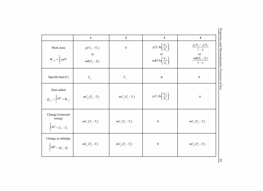
Properties and Thermodynam
ic Processes of Gas
811 2 3 4
Work done 2 1( – )p ∀ ∀ 0 21 1
1lnp
∀∀ ∀ 2 2 1 1–
1 –p p∀ ∀
γ
2
1–21
W pd= ∀∫2 1( – )mR T T 2
1lnmRT
∀ ∀
2 1( – )1 –
mR T Tγ
Specific heat (C) Cp Cv α 0
Heat added
Q1–2 = 2
1
dU∫ + W1–2
Change in internalenergy
2
1
dU∫ = U2 – U1
Change in enthalpy2
1
dH∫ = H2 – H1
or or or
mCp (T2 – T1) mCv (T2 – T1)2
1 11
lnp ∀∀ ∀ 0
mCv (T2 – T1) mCv (T2 – T1) 0 mCv (T2 – T1)
mCp (T2 – T1) mCp (T2 – T1) 0 mCp (T2 – T1)
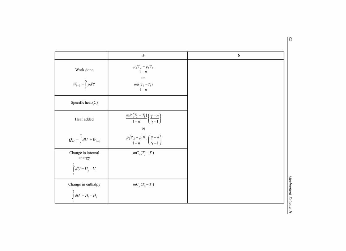
82M
echanical Science-II5 6
Work done 2 2 1 1–1 –
p pn
∀ ∀
2
1–21
W pd= ∀∫ 2 1( – )1 –
mR T Tn
Specific heat (C)
Heat added( )2 1– –1– –1
mR T T nn
γ γ
or
Q1–2 = 2
1
dU∫ + W1–22 2 1 1– –
1– –1p p n
n ∀ ∀ γ γ
Change in internal mCv (T2 – T1)energy
2
1
dU∫ = U2 – U1
Change in enthalpy mCp (T2 – T1)2
1
dH∫ = H2 – H1
or

Properties and Thermodynam
ic Processes of Gas
831 2 3 4
Change in entropyin T – S diagram
Change in entropy
2 1–S S=
Steady flow processwork done 21−W
0 ( )1 1 2 2–– 1
p pγ∀ ∀
γ1 2( – )p p∀
2
1lnp
TmC
T
or
2
1lnpmC
∀ ∀
2
1lnv
TmC
T
or
2
1lnv
pmC
p
( ) 2
1– lnp vm C C
∀ ∀
or
( ) 1
2– lnp v
pm C C
p
21 1
1lnp
∀∀ ∀
or
11 1
2ln
pp
p
∀
T2
EntropyS1
1
2
Tem
pera
ture
S2
= C
T1
T2
EntropyS1
1
2
Tem
pera
ture
S2
p = C
T1
T
EntropyS1
1 2
Tem
pera
ture
S2
T = CT
2
Entropy
1
2
Tem
pera
ture
S
T1
2

84M
echanical Science-II
5 6
Change in entropyin T – S diagram
Steady flow processwork done 21−W
( )1 1 2 2–– 1n p p
n∀ ∀
Change in entropy
12 SS −=
2 1
1 2ln ( – ) ln orp p v
T pm C C C
T p
+
2 2
1 1ln lnv p
pm C C
p ∀
+ ∀
General Gas Equation:
2 22 1
1 1– ln ( – ) ln orv p v
TS S m C C CT
∀= + ∀
( ) 2
1– lnp vm C nC
∀ ∀
or
1
2
– lnvpnmC
n p γ

Properties and Thermodynam
ic Processes of Gas
85Boiler Condenser Evaporator Nozzle
Steady flow energy equation toengineering systems
( )
( ) 212
22
222
211
21
111
2
2
−
−
++++=
++++
wgZVvpu
qgZVvpu
s
s
Turbine RotaryCompressor
ReciprocatingCompressor
1221 hhq −=− 1 2 2 1–q h h− = − 1221 hhq −=− ( )22 1 1 22V V h h= + −
1 2 1 2w h h− = − 1 2 2 1w h h− = − ( )1 2 1 2 2 1w q h h− −= + −
+++=
+++
−
−
212
22
2
211
21
1
2
2
wgZVhm
qgZVhm
orHeat
Exchanger
1–2 1 2q h h= −
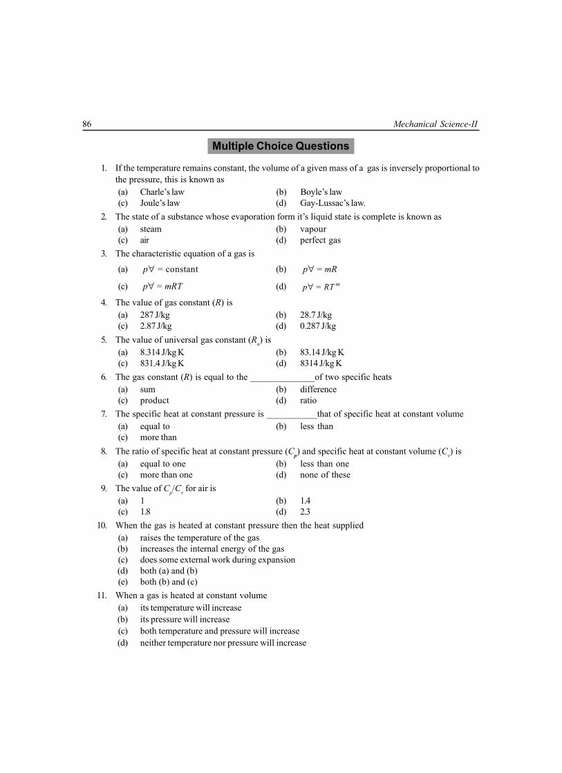
86 Mechanical Science-II
Multiple Choice Questions
1. If the temperature remains constant, the volume of a given mass of a gas is inversely proportional tothe pressure, this is known as(a) Charle’s law (b) Boyle’s law(c) Joule’s law (d) Gay-Lussac’s law.
2. The state of a substance whose evaporation form it’s liquid state is complete is known as(a) steam (b) vapour(c) air (d) perfect gas
3. The characteristic equation of a gas is
(a) = constantp∀ (b) =p mR∀
(c) =p mRT∀ (d) = mp RT∀
4. The value of gas constant (R) is(a) 287 J/kg (b) 28.7 J/kg(c) 2.87 J/kg (d) 0.287 J/kg
5. The value of universal gas constant (Rn) is(a) 8.314 J/kg K (b) 83.14 J/kg K(c) 831.4 J/kg K (d) 8314 J/kg K
6. The gas constant (R) is equal to the ______________of two specific heats(a) sum (b) difference(c) product (d) ratio
7. The specific heat at constant pressure is ___________that of specific heat at constant volume(a) equal to (b) less than(c) more than
8. The ratio of specific heat at constant pressure (Cp) and specific heat at constant volume (Cv) is(a) equal to one (b) less than one(c) more than one (d) none of these
9. The value of Cp/Cv for air is(a) 1 (b) 1.4(c) 1.8 (d) 2.3
10. When the gas is heated at constant pressure then the heat supplied(a) raises the temperature of the gas(b) increases the internal energy of the gas(c) does some external work during expansion(d) both (a) and (b)(e) both (b) and (c)
11. When a gas is heated at constant volume(a) its temperature will increase(b) its pressure will increase(c) both temperature and pressure will increase(d) neither temperature nor pressure will increase

Properties and Thermodynamic Processes of Gas 87
12. The heating of a gas at constant pressure is governed by(a) Boyle’s law (b) Charle’s law(c) Gay-Lussac’s law (d) Joule’s law
13. A process in which the gas is heated or expanded in such a way that the product of it’s pressure andvolume remains constant, is called(a) isothermal process (b) isobaric process(c) adiabatic process (d) polytropic process
14. The hyperbolic process is governed by(a) Boyle’s law (b) Charle’s law(c) Gay-Lussac’s law (d) Joule’s law
15. The heating of gas at constant _____________is governed by Boyle’s law(a) volume (b) pressure(c) temperature (d) none of these
16. In an isothermal process(a) internal energy increases (b) internal energy decreases (c) there is no change in internal energy(d) internal energy first increases and then decreases
17. The expansion ratio (r) is the ratio of
(a)∀∀
1
2
(b)∀∀
2
1
(c)∀ + ∀
∀1 2
2
(d)∀ + ∀
∀1 2
1
18. When the expansion or compression of the gas takes places according to the law np = constant∀ ,then the process is known as(a) isothermal process (b) isobaric process(c) adiabatic process (d) polytropic process
19. An adiabatic process is one in which(a) no heat enters or leaves the gas(b) the temperature of the gas changes(c) the change in internal energy is equal to the work done(d) all of the above
20. The general law of expansion or compression is the process is said to be hyperbolic if n is equal to(a) 0 (b) 1(c) 2 (d) none of these
21. If the value of n = 0 in the general law, then the process is called(a) isochoric process (b) isobaric process(c) isothermal process (d) isentropic process

88 Mechanical Science-II
22. If all the variable of a steam are independent of time it is said to be in(a) steady flow (b) unsteady flow(c) uniform flow (d) closed flow(e) constant flow
23. A control volume refers to(a) a fixed region in space (b) a specified mass(c) an isolated system (d) reversible process only(e) a closed system
24. Internal energy of a perfect gas depends on(a) temperature, specific heats and pressure(b) temperature, specific heats and enthalpy(c) temperature, specific heats and enthalpy(d) temperature only
25. In reversible polytropic process(a) true heat transfer occurs (b) the entropy remains constant(c) the enthalpy remains constant (d) the internal energy remains constant(e) the temperature remains constant
26. An isentropic process is always(a) irreversible and adiabatic (b) reversible and isothermal(c) frictionless and irreversible (d) reversible and adiabatic(e) none of these
27. The net work done per kg of gas in a polytropic process is equal to
(a) 21 1
1lnp
∀∀
∀ (b) 1 1 2( – )p ∀ ∀
(c) 12 2
2–p
∀∀ ∀
(d) 1 1 2 2––1
p pn
∀ ∀
(e) 1 1 2 2––1
p n p nn
28. Steady flow occurs when(a) conditions do not change with time at any point
(b) conditions are the same at adjacent points at any instant(c) conditions changes steadily with the time(d) /d dt∀ is constant
29. A reversible process requires that(a) there be no heat transfer(b) Newton’s law of viscosity be satisfied(c) temperature of system and surrounding be equal(d) there be no viscous or coulomb friction in the system(e) heat transfer occurs from surroundings to system only

Properties and Thermodynamic Processes of Gas 89
30. The first law of thermodynamics for steady of law(a) accounts for all energy entering and leaving a control volume(b) is an energy balance for a specific mass of fluid(c) is an expansion of the conservation of linear momentum(d) is primarily concerned with heat transfer(e) is restricted in it’s application to perfect gases
31. The characteristic equation of gases =p mRT∀ holds good for(a) monoatomic gases (b) diatomic gases(c) real gases (d) ideal gases(e) mixture of gases
32. A gas which obeys kinetic theory perfectly is known as(a) monoatomic gases (b) diatomic gases(c) real gases (d) pure gases(e) perfect gases
33. Work done in a free expansion process is(a) zero (b) minimum(c) maximum (d) positive(e) negative
34. Which of the following is not a property of the system(a) temperature (b) pressure(c) specific volume (d) heat(e) none of these
35. In a polytropic process equation = constantnp∀ . If n = 0, the process is termed as(a) constant volume (b) constant pressure(c) constant temperature (d) adiabatic(e) isothermal
36. In a polytropic process equation, if n is infinitely large, the process is termed as(a) constant volume (b) constant pressure(c) constant temperature (d) adiabatic(e) isothermal
37. The process or system that does not involve heat are called(a) isothermal process (b) equilibrium process(c) thermal process (d) steady process(e) adiabatic process
38. In a reversible adiabatic process the adiabatic ratio is equal to
(a) p
v
CC
(b) p vC C×
(c) v
p
CC
(d)2
p
v
CC
39. In isothermal process(a) temperature increases gradually (b) volume remains constant(c) pressure remains constant (d) enthalpy change is maximum(e) change in internal energy is zero
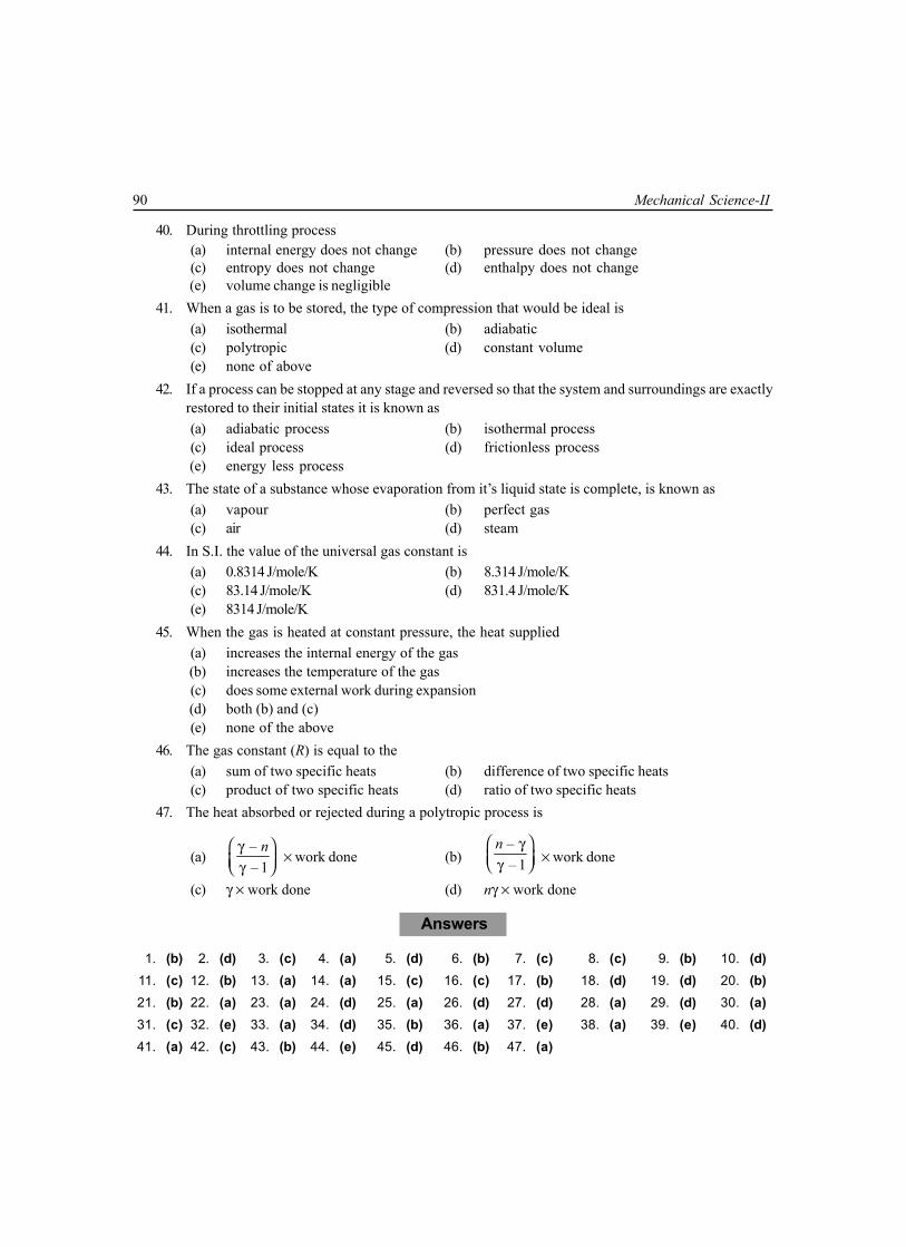
90 Mechanical Science-II
40. During throttling process(a) internal energy does not change (b) pressure does not change(c) entropy does not change (d) enthalpy does not change (e) volume change is negligible
41. When a gas is to be stored, the type of compression that would be ideal is(a) isothermal (b) adiabatic(c) polytropic (d) constant volume(e) none of above
42. If a process can be stopped at any stage and reversed so that the system and surroundings are exactlyrestored to their initial states it is known as(a) adiabatic process (b) isothermal process(c) ideal process (d) frictionless process (e) energy less process
43. The state of a substance whose evaporation from it’s liquid state is complete, is known as(a) vapour (b) perfect gas(c) air (d) steam
44. In S.I. the value of the universal gas constant is(a) 0.8314 J/mole/K (b) 8.314 J/mole/K(c) 83.14 J/mole/K (d) 831.4 J/mole/K(e) 8314 J/mole/K
45. When the gas is heated at constant pressure, the heat supplied(a) increases the internal energy of the gas(b) increases the temperature of the gas(c) does some external work during expansion(d) both (b) and (c)(e) none of the above
46. The gas constant (R) is equal to the(a) sum of two specific heats (b) difference of two specific heats(c) product of two specific heats (d) ratio of two specific heats
47. The heat absorbed or rejected during a polytropic process is
(a)–– 1
n γ γ
× work done (b)–– 1
n γ γ × work done
(c) γ × work done (d) nγ × work done
Answers
1. (b) 2. (d) 3. (c) 4. (a) 5. (d) 6. (b) 7. (c) 8. (c) 9. (b) 10. (d)11. (c) 12. (b) 13. (a) 14. (a) 15. (c) 16. (c) 17. (b) 18. (d) 19. (d) 20. (b)21. (b) 22. (a) 23. (a) 24. (d) 25. (a) 26. (d) 27. (d) 28. (a) 29. (d) 30. (a)31. (c) 32. (e) 33. (a) 34. (d) 35. (b) 36. (a) 37. (e) 38. (a) 39. (e) 40. (d)41. (a) 42. (c) 43. (b) 44. (e) 45. (d) 46. (b) 47. (a)

Properties and Thermodynamic Processes of Gas 91
NUMERICAL EXAMPLES
EXAMPLE 1Some quantity of air at a temperature of 20°C and at a pressure of 2.15 bar is found to occupy
0.20m3. The volume is kept constant when the heat energy equivalent to 20kJ is given to air. Determine the newpressure and temperature. Consider specific heat of air at constant volume 0.706 kJ/kgK. Any missing data maybe assumed.SOLUTION
Here, T1 = 20 + 273 = 293 K,
p1 =5
32.15×10
10 kPa,
1∀ = 0.20 m3, Cv = 0.706 kJ/kgK, Qv = 20 kJLet us assume R = 0.287 kJ/kgK
We know, 1 1p ∀ = mRT1
⇒ 2.15 × 100 × 0.20 = m × 0.287 × 293Therefore
m = 0.511 kgAgain, heat supplied at constant volume
vQ = mCv (T2 – T1)
⇒ 20 = 0.511 × 0.706 (T2 – 293)⇒ T2 = 348.4 K
As, 1 2
1 2=p p
T T being a constant volume process,
p2 = 1 2
1
p TT =
2.15×348.4= 2.55bar = 255kPa
293
EXAMPLE 2When 0.1421 kg of a gas is heated from 27°C to 127°C , it is observed that the gas requires 202 kJ
of heat if heated at constant pressure and 143 kJ of heat if heated at constant volume. Find the adiabatic index,gas constant and molecular weight of the gas.
SOLUTION
Here mass of the gas (m) = 0.1421 kg, initial temperature (T1) = 27 + 273 = 300 K,final temperature (T2) = 127 + 273 = 400 K,heat required at constant pressure Qp = 202 kJ,heat required at constant volume Qv = 143 kJNow, Qp = mCp (T2 – T1)⇒ 202 = 0.1421 (400 – 300)Cp

92 Mechanical Science-II
Therefore Cp = 14.125 kJ/kgKAgain, Qv = mCv (T2 – T1)⇒ 143 = 0.1421(400 – 300)Cv
Therefore Cv = 10.06 kJ/kgK
So, adiabatic index γ =14.125= = 1.4110.06
p
v
CC
Again, R = Cp – Cv = 14.125 – 10.06 = 4.065 kJ/kgK
Assuming, Rm = 8.314 kJ/kgK, M = 8.314
= 24.065
mRR
≈ .
EXAMPLE 3If 0.112m3 of gas at 27°C and 1.913 bar is compressed adiabatically to 1/5th of this volume, determine
(i) the mass of the gas (ii) the pressure and temperature at end of compression and (iii) the work done on thegas. Assume Cp = 1.005kJ/kgK, Cv = 0.718kJ/kgK.SOLUTION
Initial volume 1∀ = 0.112 m3, initial temperature T1 = (27 + 273) = 300 K,initial pressure p1 = 1.013 bar, final volume 2 1/5∀ ∀= .
Adiabatic index γ =1.005= = 1.40.718
p
v
CC
and
R = Cp – Cv = 0.287 kJ/kgK
Again we know m = 1 1
1
1.013×100×0.112= = 0.1317 kg
0.287×300pRT
∀
But p2 =γ
1.411
2= 1.013×5 = 9.642 barp
∀ ∀
Again T2 =–1
∀ ∀
γ1
2 T1 = 300 × 50.4 = 571.1 K
Work done on the gas
W1 – 2 = 2 2 1 1 2 1– ( – )= = 25.617 kJ
γ –1 γ –1p p mR T T∀ ∀
EXAMPLE 4.A system contains 0.15 m3 of a gas at a pressure of 3.8 bar and 150°C. It is expanded adiabatically
till the pressure falls to 1 bar. The gas is then heated at a constant pressure till it’s enthalpy increases by70 kJ.Determine the total work done, Take Cp = 1.00 kJ/kgK, Cv = 0.714 kJ/kgK.

Properties and Thermodynamic Processes of Gas 93
Adiabatic Expansion
Constant PressureHeating
1
2
p1
p = p3 2
1
3
2 3
SOLUTIONHere, 1∀ = 0.15 m3, p1 = 3.8 bar, p2 = 1.0 bar , T1 = 150 + 273 = 423 K, dH = 70 kJ.In Fig., process 1–2 represents adiabatic expansion of the gas and the process 2–3 represents heating atconstant pressure. First of all, let us find the temperature T2 and volume 2∀ after the adiabatic expansion.
We know that adiabatic index, γ = 1.000= = 1.40.714
p
v
CC
Now,2
423T
=
γ–1 1.4–1γ 1.41
2
3.8= = 1.4651
pp
⇒ T2 = 288.7 K
Again,2
0.15∀
=
1 1γ 1.42
1
1= = 0.385
3.8pp
⇒ 2∀ = 0.39 m3
Now let us find the temperature T3 and volume 3∀ after constant pressure heating. If m is the mass of gas
contained in the system we know that gas constantR = Cp – Cv = 0.286 kJ/kgK
And m = 1 1
1
pRT
∀=
53.8×10 ×0.15 = 0.47 kg286× 423
Increase in enthalpy dH = mCp(T3 – T2)
⇒ 70 = 0.47 × 1 (T3 – 288.7)
⇒ T3 = 437.6 KSince the heating is at constant pressure,
3∀ = 32
2
TT
∀ = 3437.60.39 = 0.59 m
288.7×

94 Mechanical Science-II
Work done during adiabatic expansion,
W1–2 =5
1 1 2 23
– (3.8×0.15 – 1.0 ×0.39)10= 45 kJγ –1 (1.4 –1)10
p p∀ ∀=
And work done during constant pressure heating,W2–3 = p2 ( 3∀ – 2∀ ) = 1.0 × 10² (0.59 – 0.39) = 20 kJ
Hence, total work done during constant pressure heating,W = W1–2 + W2–3 = 45 + 20 = 65 kJ
EXAMPLE 50.336 m3 of gas at 10 bar pressure and 150°C temperature expands adiabatically, until its pressure
is 4 bar. It is then compressed isothermally, to its original volume. Determine the final temperature and pressureof the gas. Also determine the change in internal energy. Take Cp = 0.996 kJ/kgK, Cv = 0.703 kJ/kgK.
SOLUTION
Here, 31 3 0.336 m∀ = ∀ = , p1 = 10 bar, p2 = 4.0 bar, T1 = 150 + 273 = 423 K
In figure process 1–2 represents the adiabatic expansion of the gas and the process 2–3 represents theisothermal compression to its original volume.We know that adiabatic index,
γ =0.996 1.4170.703
p
v
CC
= = and
Gas constant R = Cp – Cv = 0.293 kJ/kgK
Now,2
423T =
–1 1.417–11.4171
2
10 1.314
pp
γγ = =
⇒ T2 = 323 KSince the compression is isothermal from 2 to 3,therefore, T3 = T2 = 323 KIf final pressure of the gas is p3, for a constant volume process 3–1,
p3 = 31
1
32310 7.6 bar
423T
pT
= × =
Let us find the mass of the gas m and
m =5
1 1
1
10 10 0.336 2.7 kg293 423
pRT
∀ × ×= =
×
Change in internal energydU = U3 – U1 = mCv (T3 – T1) = 2.7 × 0.703(323 – 423) = –189.8 kJ
The negative sign indicates that there is a decrease in internal energy.
1
2
3
Adiabatic Expansion
Isothermal Compression
p1
p3
p2
A
1 =
A
3
A
2
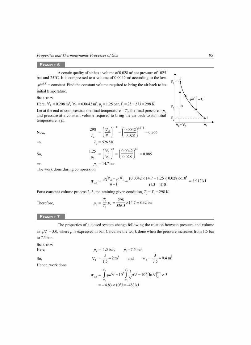
Properties and Thermodynamic Processes of Gas 95
EXAMPLE 6A certain quality of air has a volume of 0.028 m3 at a pressure of 1025
bar and 25°C. It is compressed to a volume of 0.0042 m3 according to the law1.3p∀ = constant. Find the constant volume required to bring the air back to its
initial temperature.SOLUTION
Here, 1∀ = 0.208 m3, 2∀ = 0.0042 m3, p1 = 1.25 bar, T1 = 25 + 273 = 298 K.Let at the end of compression the final temperature = T2, the final pressure = p2and pressure at a constant volume required to bring the air back to its initialtemperature is p3.
Now,2
298T
=–1
2
1
n ∀ ∀
= 1.3–10.0042
0.028 = 0.566
⇒ T2 = 526.5 K
So,2
1.25p
= 2
1
n ∀ ∀
= 1.30.0042
0.028 = 0.085
⇒ p2 = 14.7 barThe work done during compression
W1–2 =5
2 2 1 13
– (0.0042 14.7 – 1.25 0.028) 10 8.913 kJ–1 (1.3 – 1)10
p pn
∀ ∀ × × ×= =
For a constant volume process 2–3, maintaining given condition, T3 = T1 = 298 K
Therefore, p3 = 32
2
29814.7 8.32 bar
526.5T
pT
= × =
EXAMPLE 7The properties of a closed system change following the relation between pressure and volume
as p∀ = 3.0, where p is expressed in bar. Calculate the work done when the pressure increases from 1.5 barto 7.5 bar.
SOLUTION
Here, p1 = 1.5 bar, p2 = 7.5 bar
So, 1∀ = 33 2 m1.5
= and 2∀ = 33 0.4 m7.5
= Hence, work done
W1–2 = [ ]2 2
1 1
0.45 52
310 10 ln 3pd d
∀ ∀
∀ ∀
∀ = ∀ = ∀ ×∀∫ ∫
= – 4.83 × 10⁵ J = –483 kJ
1
2
3
p1
p3
p2
A
2 =
A
3
A
1
p
A1.3= C
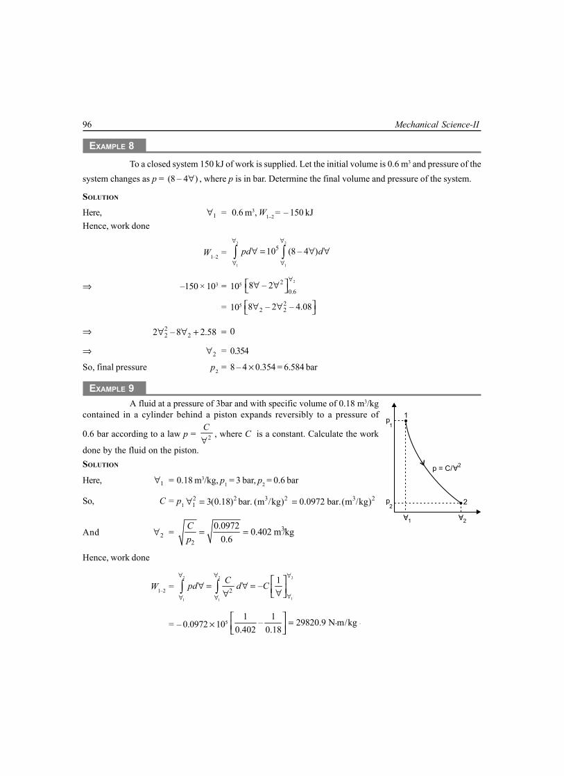
96 Mechanical Science-II
EXAMPLE 8To a closed system 150 kJ of work is supplied. Let the initial volume is 0.6 m3 and pressure of the
system changes as p = (8 – 4 )∀ , where p is in bar. Determine the final volume and pressure of the system.
SOLUTION
Here, 1∀ = 0.6 m3, W1–2 = – 150 kJHence, work done
W1–2 =2 2
1 1
510 (8 – 4 )pd d∀ ∀
∀ ∀
∀ = ∀ ∀∫ ∫
⇒ –150 × 103 = 105 22
0.68 – 2
∀ ∀ ∀
= 105 22 28 – 2 – 4.08 ∀ ∀
⇒ 22 22 – 8 2.58∀ ∀ + = 0
⇒ 2∀ = 0.354
So, final pressure p2 = 8 – 4 × 0.354 = 6.584 bar
EXAMPLE 9A fluid at a pressure of 3bar and with specific volume of 0.18 m3/kg
contained in a cylinder behind a piston expands reversibly to a pressure of
0.6 bar according to a law p = 2C∀
, where C is a constant. Calculate the work
done by the fluid on the piston.SOLUTION
Here, 1∀ = 0.18 m3/kg, p1 = 3 bar, p2 = 0.6 bar
So, C = p12 2 3 2 3 21 3(0.18) bar. (m /kg) 0.0972 bar.(m /kg)∀ = =
And 2∀ = 3
2
0.0972 0.402 m /kg0.6
Cp
= =
Hence, work done
W1–2 =2 2 2
11 1
21–Cpd d C
∀ ∀ ∀
∀∀ ∀
∀ = ∀ = ∀∀ ∫ ∫
= – 0.0972 × 10⁵ 1 1 .– 29820.9 N m/kg
0.402 0.18 =
.
2
1p
1
p2
A
2
p = C/
A2
A
1

Properties and Thermodynamic Processes of Gas 97
EXAMPLE 10A cylinder contains 1 kg of a certain fluid at an initial pressure
of 20 bar. The fluid is allowed to expand reversibly behind a piston
according to a law 2p∀ = constant, until the volume is doubled. Thefluid is then cooled reversibly at constant pressure until the pistonregains its original position. Heat is then supplied reversibly with thepiston firmly locked in position until the pressure rises to the originalvalue of 20 bar. Calculate the net work done by the fluid for an initialvolume of 0.05 m3.
SOLUTION
Here, m = 1 kg, p1 = 20 bar, 1∀ = 0.05 m3, 2∀ = 2 × 0.05 = 0.1 m3
Now, p2 =2 2
1 11
2 120 5 bar
2p
∀ ∀= = ∀ ∀
Work done by the fluid from 1 to 2.
W1–2 =2 2 2 2
1 11 1
21 12
1 1– –Cpd d C p∀ ∀ ∀ ∀
∀ ∀∀ ∀
∀ = ∀ = = ∀ ∀ ∀∀ ∫ ∫
= – 20 × 105 × 0.0025 1 1 .– 50000N m 50 kNm
0.1 0.05 = =
And work done during constant pressure process, from 2 to 3
W2–3 = 2 2 3( – )p ∀ ∀ = 5 × 10⁵ (0.1 – 0.05) = 25000 N.m = 25 kNmIn constant volume process from 3 to 1, W2–3 = 0.Net work done by the fluid,
W = W1–2 – W2–3 = 50 – 25 = 25 kN.m
EXAMPLE 11(a)A gas is enclosed in a piston cylinder assembly as a system. The gas is initially at a pressure of
500 kPa and occupies a volume of 0.2 m3. The gas is taken to the final statewhere p2 = 100 kPa by following two different processes. Calculate thework done by the gas in each case when: (a) the volume of the gas isinversely proportional to the pressure and (b) the process follows the
path p γ∀ = constant, where γ = 1.4.
SOLUTION
(a) The path followed by the system 1p
∀ ∝ i.e., p∀ = constant
So, 2
1
∀∀
= 1 1 1
2and
p pp
p∀
=∀
Pre
ssure
1
23
Consta
nt
Volu
me
Constant Pressure
p1
p2
p
A2= C
A
2
A
1
A
3= Volume
Pre
ssu
re
1
2
p1
p2
A
2
A
1Volume

98 Mechanical Science-II
Hence work done,
W1–2 =2 2
1 1
1 1dpd p
∀ ∀
∀ ∀
∀∀ = ∀
∀∫ ∫
= 21 1
1lnp
∀∀ ∀
= 11 1
2ln pp
p
∀
= (500 × 103 × 0.2 ln 5) J= 160.94 kJ
(b) The path followed by the system, 1 21 2.p pγ γ∀ = ∀
So, 2
1
γ ∀ ∀
= 1
2
pp
and 2∀ =1/ 1/1.4
311
2
500× 0.2 = 0.6313 m
100pp
γ ∀ = Hence work done,
W1–2 =3
1 1 2 23
– (500 × 0.2 – 100 × 0.6313)10 92.175 kJ–1 (1.4 –1) 10
p p∀ ∀= =
γ ×
EXAMPLE 11(b)Determine the total work done by a gas system following an expansion process as shown in the
figure. Initial pressure of the system is (50 E + 2) kPa
Pre
ssure
B
C
p1
p2
Volume
A
0.2 0.4 0.8
p
A1.3= Constant
SOLUTION
Being a constant pressure process,WA – B = 50 × 100 (0.4 – 0.2) = 1000 kJ
Again, 1 1p γ∀ = 2 2p γ∀

Properties and Thermodynamic Processes of Gas 99
Therefore, p2 =1.3
11
2
0.4 × 50 ×100 = 2030.63 kPa0.8
pγ ∀ = ∀
Again, WB – C = 1 1 2 2– (50 ×100 × 0.4 – 2030.63 × 0.8)1251.65 kJ
– 1 1.3 –1p p∀ ∀
= =γ
Hence, total workdone WA – C = WA – B + WB – C = 1000 + 1251.65 = 2251.65 kJ
EXAMPLE 12A piston and cylinder arrangement containing a fluid system has a stirring device as shown in
the figure. The piston is frictionless and it is held down against the fluid due to atmospheric pressure of101.3 kPa.The stirring device is turned 9500 revolutions with an average torque against the fluid of 1.25 N.m.Meanwhile the piston of 0.65 m diameter moves out 0.6 m. Determine the net work transfer for the system.
W1W2
Stirrer
System
Cylinder
0.6 m
SOLUTION
Here, work done by the stirring device upon the systemW1 = 2πNT = 2π × 9500 × 1.25 = 74612.83 N.m = 74.613 kJ
This is a negative workWork done by the system upon the surroundings
W2 = pAL = 101.3 × 20.65 ×0.6 = 20.168 kJ4π ×
Hence, net work transfer for the system.= – 74.613 + 20.168 = – 54.445 kJ
EXAMPLE 13A piston and cylinder arrangement containing a fluid system has a stirring device in the cylinder.
The piston is frictionless and it is held down against the fluid due to the atmospheric pressure of 101.325 kPa.The stirring device is turned 10000 revolutions with an average torque against the fluid of 1.275 Nm. Meanwhilethe piston of 0.6 m diameter moves out 0.8 m. Compute the net work transfer for the system.
SOLUTION
Here, work done by the stirring device upon the systemW1 = 2πNT = 2π × 10000 × 1.275 = 80110.61 Nm = 80.11 kJ
It is a negative work

100 Mechanical Science-II
Work done by the system upon the surroundings
W2 = pAL = 101.325 × 20.6 × 0.8 = 22.92 kJ4π ×
Hence, net work transfer for the system.= – 80.11 + 22.92 = –57.19 kJ
EXAMPLE 14A balloon which is initially collapsed is slowly inflated with helium from a cylinder forming the
balloon into a sphere of 5 m in diameter. The atmospheric pressure is 100 kPa. During the filling process thehelium inside the cylinder remains constant at 300 K all the time. Determine the work by the cylinder-balloonsystem.
InflatedBalloon
Valve
HeliumBottle
p1
p2
Balloon Initially Flat
SOLUTION
Here displacement work
WD = ( ) ( )balloon bottle
pd pd∀ + ∀∫ ∫
= ( )3
2 14 5– 0 100 ×3 2
p ∀ ∀ + = π
= 6544.98 kJ = 6.545 MJ
EXAMPLE 15A spherical balloon of 1 m diameter contains a gas at 150 kPa. The gas inside the balloon is heated
until the pressure increases to 450 kPa. During the process of heating, pressure of the gas inside the balloon isproportional to the cube of the diameter of the balloon. Determine the work done by the gas inside the balloon.
SOLUTION
Here, 3p D∝ ⇒ p = C.D3
Substituting p = 150 kPa and D = 1 m, we have
C = 33 3
150 150 kPa/m .1
pD
= =

Properties and Thermodynamic Processes of Gas 101
When p = 450 kPa
D = 3 450 1.4422 m150
=
Now we can consider, D1 = 1 m, D2 = 1.4422 m
Again, ∀ =3 34
3 2 6D Dπ π =
So, d∀ =2
236 2
DD dD dDπ π× × = ×
Hence work done
W =2 2
1 1
2 23 5
1
.2 2
D D
D D
D Cpd CD dD D dDπ π∀ = =∫ ∫ ∫
=
1.44176
12 6C D π
= 6 6150. [1.4422 –1 ]
2 6π
= 314.09 kJ
EXERCISE
1. Write the characteristic equation of a perfect gas, name symbols and state their unit in S.I. Distinguishbetween specific gas constant and universal gas constant.
2. Derive an expression for heat transfer during polytropic process.
3. Establish a relation between the two specific heat of gas and specific gas constant.
4. Distinguish between gas and vapour.
5. What is perfect gas and what is real gas? Under what condition does a real gas behave as a perfectgas?
6. Establish a relation amongst , ,p T∀ in adiabatic process.
7. What do you understand by enthalpy? Show that for a constant pressure, the heat supplied to the gasis equal to change of enthalpy.
8. What do you understand by a thermodynamic process?
9. Explain the difference between non flow process and a flow process. Derive the equation for workdone during a non-flow process.
10. State the law of corresponding states.

102 Mechanical Science-II
11. Define the compressibility factor and explain its significance.12. A quantity of gas is compressed from 130 kPa and 38°C to 1.25 MPa and 280°C in an engine cylinder.
Find the law of the process and determine per kg of the gas the work transfer. Take R = 0.287 kJ/kg forthe gas.
Ans. [ 1.299 = ,p C∀ W = –238.28 kJ/kg ]
13. A certain gas has Cp =1.9681.507 kJ/kgK and Cv =1.507 kJ/kgK. Find its molecular weight and the gasconstant.
14. A constant volume chamber of 0.3 m3 capacity contain 2 kg of this gas at 5°C. Heat is transferred to thegas until the temperature becomes 100°C. Find the work done, the heat transferred, and the changesin internal energy, enthalpy and entropy.
15. 0.2 m3 of mixture of fuel and air at 1.2 bar and 60°C is compressed until it’s pressure becomes 12 bar andtemperature becomes 270°C,then it is ignited suddenly at constant volume and its pressure becomestwice the pressure at the end of compression. Calculate the maximum temperature reached and changein internal energy. Also compute the heat transfer during the compression process. Consider mixtureas a perfect gas and take = 1.072 kJ/kgK and R = 294 J/kgK.
Ans. [813°C, 143.5 kJ, –16 kJ]
16. An ideal gas at 30°C and 1 bar is compressed adiabatically from 5 m3 to 1 m3. Find the temperature,pressure and work done. Take = 1.4
Ans. [304°C, 9.5 bar, 1.125 kJ]
17. A cylinder contains 0.084 m3 of hydrogen at 7.05 bar and 18°C. It is then compressed adiabatically to14 bar and then expanded isothermally to the original volume of 0.084 m3. Characteristic constant forhydrogen is 4200 J/kgK and its specific heat at constant pressure is 14.28 kJ/kgK. Determine the finalpressure of the gas and the amount of heat which must be added to the gas during isothermalexpansion. Also calculate the heat which must be substracted from the gas after expansion in order toreduce it to its initial state of stressor.
Ans. [2.25 bar, 34.5 kJ, 24.14 kJ]

4.1 INTRODUCTIONWhen a thermodynamic system undergoes aprocess or a combination of processes, as aresult of which the system can be restored to itsinitial state, then the system is said to haveundergone a cyclic process or a cyclic change.It is seen from figure 4.1 that a thermodynamiccycle may be the combination of any number ofprocesses. But the minimum number ofprocesses required to complete a cycle is twoas shown in figure 4.1(c), where process 1 to 2and 2 to 1 comprising the cycle.
4.2 JOULE’S EXPERIMENTJoule carried out a series of experiment during 1843 and1848 that subsequently led to the formulation of the firstlaw of thermodynamics. Of the several experimentsconducted by Joule, the paddle wheel experiment describedbelow is considered as a classical one.
This experiment consisted of two-process cycle arrivedout on a system comprising of a fluid as shown in figure4.2., where work W was done on the system by means ofa paddle wheel. The paddle wheel was made to rotate bylowering the mass which is tied to a string and the stringwas wound on the paddle wheel as shown in Fig. 4.2 (a).While lowering the mass m through a distance Z, work wasdone on liquid (the system) and the amount of work doneon the system was measured. This caused a rise intemperature of fluid and the system has reached a different
4CHAPTER
FIRST LAW OF THERMODYNAMICS
AND ITS APPLICATION
1
2
3
4
4 Processes 3 Processes 2 Processes
11
2
23
(a) (b) (c)
Property
Pro
pe
rty
Fig. 4.1
Fig. 4.2 (a)
Insulation
W
mgSystem Boundary
Process 1-2 (Paddle-WheelWork Entering the System)
Fluid
z

104 Mechanical Science-II
state. The system was then placed in contact with a water bath as shown in figure 4.2. Heat wasthus transferred from the fluid to the water in process 2-1, until the original state of the fluid wasrestored, as indicated by its temperature. Heat Q was measured from the increase in energy ofwater bath.
Insulation
Process 2-1 (Heat Leaving the System)
Q
T
Waterbath
Fluid
System Boundary
Fig. 4.2 (b)
Joule carried out several experiments involving different types of work interaction. Based onthese experimental results Joule found that the net work done on the system is exactly equal to thenet heat interaction, irrespective of the type of the work interaction, the rate at which work was doneand the method employed for transferring the energy in the form of heat from the system. That is
( ) ( )from the system on the system
or – 0.Q W Q Wδ = δ δ δ =∫ ∫ ∫ ∫ Here ∫ denotes integral over a cycle or
cyclic integral.
4.3 FIRST LAW OF THERMODYNAMICS FOR A SYSTEM UNDERGOING ATHERMODYNAMICS CYCLE
The conclusion from the Joule’s experiments leads to the statement of the first law of thermodynamicsas follows:
When a closed system undergoes a thermodynamic cycle, during a cycle the cyclic integralof heat transfer is equal to the cyclic integral of work transfers.
Mathematically Q Wδ = δ∫ ∫ (4.1)
Here denotes integral over a cycle or cyclic integral ∫ has been used to indicate the both Q andW are inexact differentials.
When heat Q and work W are in different units, then a proportionality factor, called themechanical equivalent of heat, denoted by a symbol J is required. So, the first law may be statedas follows, Whenever a system undergoes a cyclic change, the algebraic sum of work transfersis proportional to the algebraic sum of heat transfers or work and heat are mutually convertibleone into other.
Mathematically, J Q Wδ = δ∫ ∫ (4.2)

First Law of Thermodynamics and its Application 105
In M.K.S unit J = 427 kgfm/kcal, If SI is used for heat and work, then J = 1. So it is notnecessary to use any proportionality factor in the first law equation.
4.4 THE IMPORTANT CONSEQUENCES OF THE FIRST LAW OFTHERMODYNAMICS
The first law of thermodynamics leads to the following important consequences.1. Heat interaction is a path function.2. Energy is a property of a thermodynamic system.3. The energy of an isolated system is conserved.4. A perpetual motion machine of the first kind is impossible.
A
B
C
E
1
2
E – E2 1
p
E1E2
Fig. 4.3
4.4.1 Heat Interaction is a Path FunctionEquation (4.1) states the first law for a thermodynamic cycle. But many times we are concernedwith heat and work interaction of a system during a single thermodynamic process. We, thereforeneed the formulation of first law for a process. Referring figure 4.3, suppose a system follows thepath 1-A-2 in reaching the final state 2 starting from the initial state 1. Then the system can berestored to the initial state 1 either by the path 2-B-1 or 2-C-1. Then the combination of the processesleads to two different cycles, namely 1-A-2-B-1 and 1-A-2C-1. Applying the first law thermodynamicsto the cycles 1-A-2-B-1 and 1-A-2-C-1 we get:
1– –2 2– –1 1– –2 2– –1
– – 0A B A B
Q Q W Wδ + δ δ δ =∫ ∫ ∫ ∫ (4.3)
and1– –2 2– –1 1– –2 2– –1
– – 0A C A C
Q Q W Wδ + δ δ δ =∫ ∫ ∫ ∫ (4.4)
Subtracting equation (4.4) from equation (4.3), we get
2– –1 2– –1 2– –1 2– –1
– – 0B C B C
Q Q W Wδ δ δ + δ =∫ ∫ ∫ ∫

106 Mechanical Science-II
or,2– –1 2– –1 2– –1 2– –1
– – 0B C B C
Q Q W Wδ δ = δ δ =∫ ∫ ∫ ∫ (4.5)
We know that work interaction is a path function and δ∫ W represents the area under the – ∀p
curve. Hence,
2– –1 2– –1
– 0B C
W Wδ δ ≠∫ ∫ (4.6)
So, from equation (4.5) and (4.6) we get,
2– –1 2– –1 2– –1 2– –1
– 0 orB C B C
Q Q Q Qδ δ ≠ δ ≠ δ∫ ∫ ∫ ∫ (4.7)
That is, the heat interaction along the path 2-B-1 is different from the heat interaction along thepath 2-C-1. Thus, heat interaction depends on the path followed by a system and heat interaction isa path function. It is not a point function or state function and hence it’s differential is not exact.Heat interaction is not a property of a thermodynamic system.
4.4.2 Energy is a Property of a Thermodynamic SystemFor the purpose, consider the change of state of a system from 1 to 2, along path A and then from 2to 1 along path B and C, thus completing two different cycles, namely 1-A-2-B-1 and 1-A-2-C-1, asshown in figure 4.3 . According to the first law of thermodynamics for both the cycle 1-A-2-B-1 and1-A-2-C-1 we get from equation (4.5),
( ) ( )2– –1 2– –1
– – –B C
Q W Q Wδ δ = δ δ∫ ∫ (4.8)
We know that Qδ∫ and Wδ∫ each depends on the path followed by a system. Equation (4.8)
shows that the value of ( )–Q Wδ δ∫ connecting the states 1 and 2 is the same for the processes 2-
B-1 and 2-C-1. In other words the quantity ( )–Q Wδ δ does not depend on the path followed by asystem, but depends only on the initial and the final states of a system. Hence, the quantity ( )–Q Wδ δ isan exact differential, thus is a property of a system. Thus, property is called the energy E, and thenthe differential change in the energy of a system is given by
–dE Q W= δ δ (4.9)
Here dE is an exact differential. That is, there exits a property called the energy of the systemand its differential change is related to the work and heat interactions. We also know that the energyof a system is sum of macroscopic and microscopic modes of energy and is given by
E KE PE U= + + (4.10)Where KE = Kinetic Energy, PE= Potential Energy, and U= Internal Energy.Comparing equations (4.9) and (4.10), we get
( ) ( ) –dE d KE d PE dU Q W= + + = δ δ

First Law of Thermodynamics and its Application 107
So, change in the value of energy is the algebraic sum of the heat supply and the work doneduring any change in state. This is called the corollary 1 of the first law of thermodynamics.
4.4.3 The Energy of an Isolated System is Conserved (Law of the Conservation ofEnergy)
The energy can neither be created nor destroyed though it can be transformed from one form toanother. In an isolated system, the energy of the system remains constant. According to this law,when a system undergoes a change of state, then both heat transfer and work transfer take place. Thenet energy transfer is stored within the system and is known as stored energy or total energy of thesystem. Mathematically, –dE Q W= δ δ . On integrating this expression for a change of state from 1to 2, we get,
1–2 1–2 2 1– –Q W E E= (4.11)
When 1–2Q = heat transferred to the system during the process from state 1 to 2, 1–2W = workdone by the system on the surrounding during the process,
E1 = total energy of the system at state 1 2
11 1 1 1 1,
2mVPE KE U mgZ U= + + = + +
E2 = total energy of the system at state 2 2
22 2 2 2 22
mVPE KE U mgZ U= + + = + + .
Thus, the above equation (4.11) may be re-written as 1–2 1–2 2 1– –Q W E E=
( ) ( )2 2 2 1 1 1–PE KE U PE KE U= + + + +
( ) ( )2 2
2 12 1 2 1– – –
2 2V Vm gZ gZ m U U
= + + (4.12)
For unit mass this expression gets converted to
( ) ( )2 2
2 11–2 1–2 2 1 2 1– – – –
2 2V Vq w g Z Z u u
= + + (4.13)
Case (1): When there is no change in potential energy of the system i.e., when the height of the
system from the datum level is same ( )2 1Z Z= , then 2 1PE PE= . Thus, the equation (4.12) will be
( )2 2
2 11–2 1–2 2 1– – –
2 2V VQ W U U
= + (4.14)
Case (2): When there is no change in potential energy and also there is no flow of the mass into orout of the system , then 2 1PE PE= and 2 1KE KE= . Thus, the equation (4.12) takes the form
( )1–2 1–2 2 1– –Q W U U dU= = (4.15)
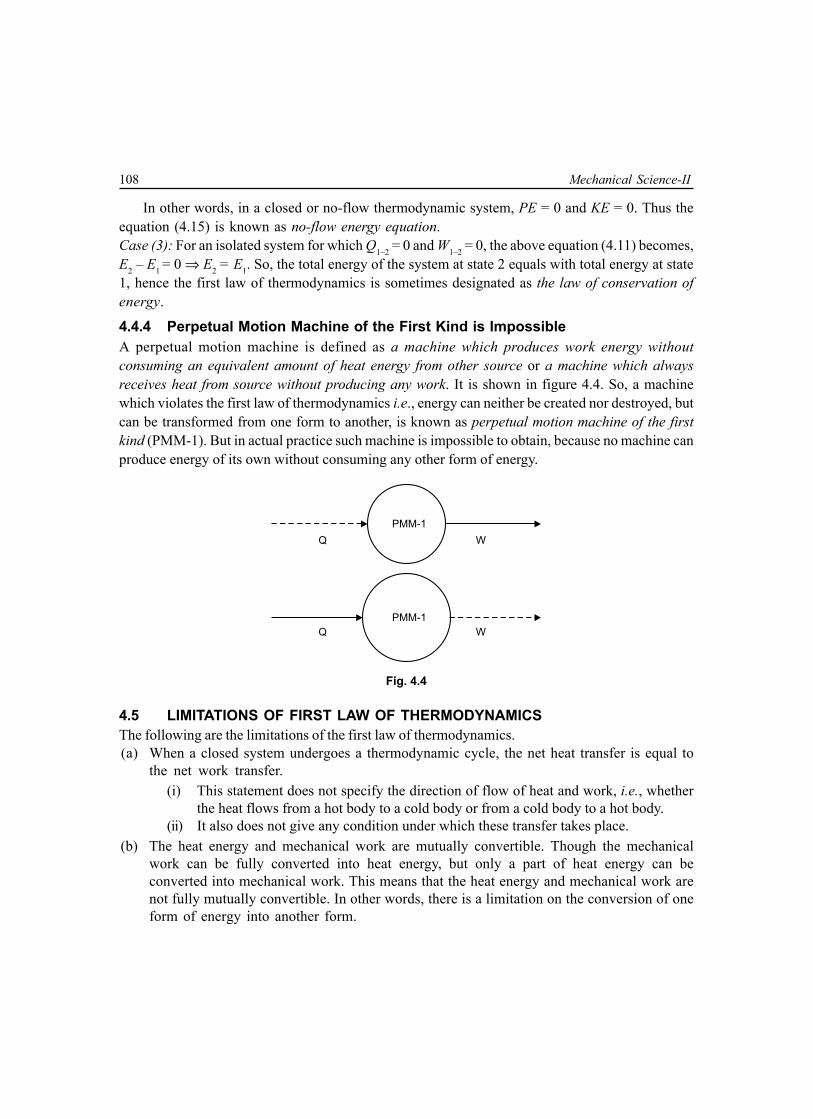
108 Mechanical Science-II
In other words, in a closed or no-flow thermodynamic system, PE = 0 and KE = 0. Thus theequation (4.15) is known as no-flow energy equation.Case (3): For an isolated system for which Q1–2 = 0 and W1–2 = 0, the above equation (4.11) becomes,E2 – E1 = 0 ⇒ E2 = E1. So, the total energy of the system at state 2 equals with total energy at state1, hence the first law of thermodynamics is sometimes designated as the law of conservation ofenergy.
4.4.4 Perpetual Motion Machine of the First Kind is ImpossibleA perpetual motion machine is defined as a machine which produces work energy withoutconsuming an equivalent amount of heat energy from other source or a machine which alwaysreceives heat from source without producing any work. It is shown in figure 4.4. So, a machinewhich violates the first law of thermodynamics i.e., energy can neither be created nor destroyed, butcan be transformed from one form to another, is known as perpetual motion machine of the firstkind (PMM-1). But in actual practice such machine is impossible to obtain, because no machine canproduce energy of its own without consuming any other form of energy.
PMM-1
PMM-1
Q W
Q W
Fig. 4.4
4.5 LIMITATIONS OF FIRST LAW OF THERMODYNAMICSThe following are the limitations of the first law of thermodynamics.(a) When a closed system undergoes a thermodynamic cycle, the net heat transfer is equal to
the net work transfer.(i) This statement does not specify the direction of flow of heat and work, i.e., whether
the heat flows from a hot body to a cold body or from a cold body to a hot body.(ii) It also does not give any condition under which these transfer takes place.
(b) The heat energy and mechanical work are mutually convertible. Though the mechanicalwork can be fully converted into heat energy, but only a part of heat energy can beconverted into mechanical work. This means that the heat energy and mechanical work arenot fully mutually convertible. In other words, there is a limitation on the conversion of oneform of energy into another form.

First Law of Thermodynamics and its Application 109
4.6 APPLICATION OF FIRST LAW THERMODYNAMICS TO A NON-FLOW PROCESSWhen a system undergoes a change of state or a thermodynamic process then both the heat transferand work transfer takes place. The net energy transfer is stored within the system and is known asstored energy or total energy of the system and which was discussed in equation (4.11).
2
1–2 1–2 2 11
– –Q W dE E E= =∫ (4.16)
For non-flow process the stored energy is the internal energy only. Thus, equation (4.16) whenapplied to a non-flow process or a static system may be written as
2
1–2 1–2 2 11
– –Q W dU U U= =∫ (4.17)
It may be noted that heat and work are not properties of the system, but their difference
( )1–2 1–2–Q W during a process is the numerical equivalent of stored energy. Since the stored energy
is a property, therefore ( )1–2 1–2–Q W is also a property.
4.6.1 Types of Non-Flow ProcessNon-flow processes are of two types(a) Reversible non-flow process: All the different reversible
non-flow processes as applicable for perfect gas arediscussed in detail in the previous chapter.
(b) Irreversible non-flow process (free or unresistedexpansion process): The free expansion process is anirreversible process. A free expansion occurs when afluid is allowed to expand suddenly into a vacuumchamber through an orifice of large dimension.
Let us consider the insulated container is divided into twochambers A and B by a partition as shown in figure 4.5(a). Thechamber A contains a perfect gas having volume 1∀ , pressurep1 and temperature T1 while the chamber B is completelyvacuum. As these chambers are insulated, no heat transfer takesplace from its surroundings. Now, if the partition is removed,the gas will expand freely and occupy the whole space as shownin figure 4.5(b). By this, the volume of gas increases to 2∀ ,pressure decreases to p2 and the temperature may also decreaseto T2. Since there is no expansion of the boundary of the systembecause it is rigid, therefore no work is done. Thus for a freeexpansion process of gas following points may be noted:
Fig. 4.5 (a)
Boundary
A
GAS BVacuum
Insulation
Partition
( T1 1p 1)
Fig. 4.5 (b)
BoundaryInsulation
(p T1 2 1)

110 Mechanical Science-II
1. Since the system is perfectly insulated, no heat transfertakes place. So, Q1–2 = 0, therefore, the expansion of thegas may be called as an adiabatic expansion.
2. Since the free expansion of the gas from the equilibriumstate 1 to the equilibrium of state 2 takes place suddenly,therefore the intermediate states out not be in equilibriumstates, as shown on the –p ∀ diagram in figure 4.5(c),thus the process is reversible and expansion is thereforeknown as is reversible adiabatic expansion.
3. Since there is no resistance to overcome during freeexpansion process, therefore no work is done by the system,i.e., W1–2 = 0, thus the free expansion process is also knownas unresisted expansion process.
4. According to the first law of thermodynamics, Q1–2 = W1–2 + 2
1
dU∫ (4.18)
Since for free expansion, Q1–2 = 0 and W1–2 = 0, therefore the change in internal energy,
2
1
dU∫ = U2 – U1 = 0 ⇒ U2 = U1 (4.19)
In other words, the internal energy of the system in a free expansion process remains constant.Thus, the free expansion process is also known as constant internal energy process.
1. We know the change in internal energy 2
1
dU∫ = mCv (T2 – T1) (4.20)
Since 2
1
dU∫ = 0, mCv (T2 – T1) = 0, which leads to T2 = T1 (4.21)
So, there is no change in temperature of the system. In other words no temperature of thesystem, in a free expansion process remains constant. But it cannot be called an isothermal
process, because in an actual isothermal process, work done by the gas is 21–2 1 1
1lnW p
∀= ∀ ∀ but
in free expansion process work done. W1–2 = 0.2. We know that the change in enthalpy
2
1
dT∫ = H2 – H1 = mCp
2
1
dT∫ = mCp (T2 – T1) (4.22)
Fig. 4.5 (c)
Pre
ssu
re(p
)
Volume ( )
1
2
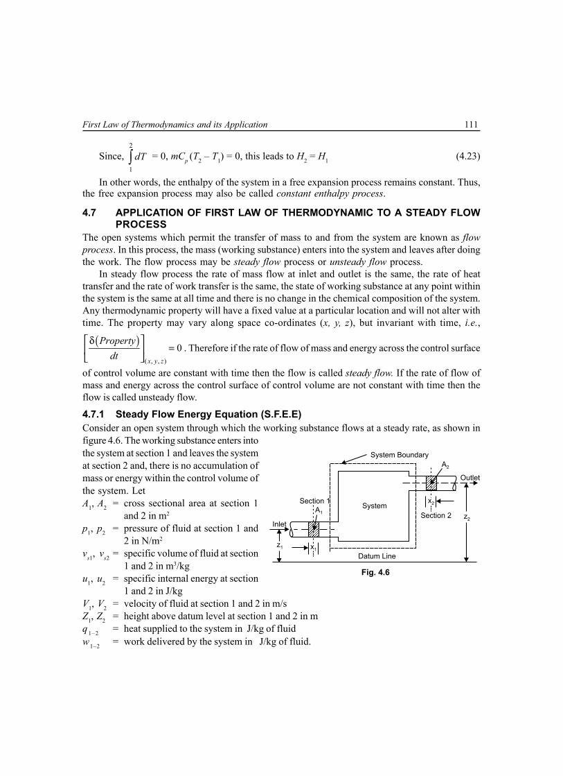
First Law of Thermodynamics and its Application 111
Since, 2
1
dT∫ = 0, mCp (T2 – T1) = 0, this leads to H2 = H1 (4.23)
In other words, the enthalpy of the system in a free expansion process remains constant. Thus,the free expansion process may also be called constant enthalpy process.
4.7 APPLICATION OF FIRST LAW OF THERMODYNAMIC TO A STEADY FLOWPROCESS
The open systems which permit the transfer of mass to and from the system are known as flowprocess. In this process, the mass (working substance) enters into the system and leaves after doingthe work. The flow process may be steady flow process or unsteady flow process.
In steady flow process the rate of mass flow at inlet and outlet is the same, the rate of heattransfer and the rate of work transfer is the same, the state of working substance at any point withinthe system is the same at all time and there is no change in the chemical composition of the system.Any thermodynamic property will have a fixed value at a particular location and will not alter withtime. The property may vary along space co-ordinates (x, y, z), but invariant with time, i.e.,
( )( , , )
0x y z
Propertydt
δ=
. Therefore if the rate of flow of mass and energy across the control surface
of control volume are constant with time then the flow is called steady flow. If the rate of flow ofmass and energy across the control surface of control volume are not constant with time then theflow is called unsteady flow.
4.7.1 Steady Flow Energy Equation (S.F.E.E)Consider an open system through which the working substance flows at a steady rate, as shown infigure 4.6. The working substance enters intothe system at section 1 and leaves the systemat section 2 and, there is no accumulation ofmass or energy within the control volume ofthe system. LetA1, A2 = cross sectional area at section 1
and 2 in m2
p1, p2 = pressure of fluid at section 1 and2 in N/m2
vs1, vs2 = specific volume of fluid at section1 and 2 in m3/kg
u1, u2 = specific internal energy at section1 and 2 in J/kg
V1, V2 = velocity of fluid at section 1 and 2 in m/sZ1, Z2 = height above datum level at section 1 and 2 in mq 1–2 = heat supplied to the system in J/kg of fluidw1–2 = work delivered by the system in J/kg of fluid.
System Boundary
Outlet
A2
x2
z2
x1
A1
z1
Datum Line
System
Inlet
Section 2
Section 1
Fig. 4.6

112 Mechanical Science-II
Consider 1 kg of mass of the fluid (working substance). We know that total energy (J/kg)entering the system per kg of working fluid at section 1 is e1
So, 2
11 1 1 1 1 1–22s
Ve u p v gZ q= + + + + (4.24)
Here flow energy or displacement energy or flow work is the energy required to flow or movethe working fluid against its pressure. Flow work or energy
( ) ( )1 1 1 1 1 1 1 1sFE p A x p A x p v= = = (4.25)Similarly, total energy (J/kg) leaving the system per kg of working fluid at section 2 is e2
So, 2
22 2 2 2 2 1–22s
Ve u p v gZ w= + + + + (4.26)
Assuming no loss of energy during flow, then according to law of conservation of energy 1 2e e=
⇒2 2
1 21 1 1 1 1–2 2 2 2 2 1–22 2s s
V Vu p v gZ q u p v gZ w+ + + + = + + + + (4.27)
Again we know that, specific enthalpy of working fluid h = u + pvsThus, equation (4.27) may be re-written as
2 21 2
1 1 1–2 2 2 1–22 2V Vh gZ q h gZ w+ + + = + + + (4.28)
Otherwise,
1 1 1 1–2 2 2 2 1–2h ke pe q h ke pe w+ + + = + + + (4.29)
It may be noted that all the terms in equation (4.28) represent the energy flow per unit mass ofthe working fluid, i.e., in J/kg. If m1, m2 be the mass flow rate of working fluid in kg/s then, for asteady flow, m1 = m2 = m, i.e., mass flow rate at section 1 equals with mass flow rate at section 2.When the equation (4.28) is multiplied through by the mass (m) in kg/s, then all the term willrepresent the energy flow per unit time, i.e., in J/s.
Thus the equation (4.28) may be re-written as2 2
1 21 1 1–2 2 2 1–22 2
V Vm h gZ q m h gZ w
+ + + = + + + (4.30)
Both the equations (4.28) and (4.30) are known as steady flow energy equation (S.F.E.E.). Thesteady flow energy equation (4.28) for unit mass flow may be rearranged as
( ) ( )2 2
2 11–2 1–2 2 1 2 1– – – –
2 2V Vq w h h g Z Z
= + +
( ) ( ) ( )2 1 2 1 2 1– – –h h ke ke pe pe= + + (4.31)

First Law of Thermodynamics and its Application 113
In differential form, S.F.E.E. takes the shape as
( ) ( )–q w dh d ke d peδ δ = + + (4.32)In thermodynamics, the effect of gravity is generally neglected. Therefore equation (4.31) may
be re-written as
( )2 2
2 11–2 1–2 2 1– – –
2 2V Vq w h h
= + (4.33)
Again if V1 = V2, then equation (4.33) will be reduced to
( )1–2 1–2 2 1– –q w h h= (4.34)In non-flow process the flow work at inlet and outlet is zero, i.e., p1vs1 = 0 = p2vs2. Therefore,
h1 = u1 and h1 = u2.Thus, the equation (4.34) will be q1–2 – w1–2 = (u2 – u1) (4.35)
4.8 MASS BALANCE (CONTINUITY) EQUATIONIn steady flow the mass flow rate (m) of the working fluid entering and leaving the system at sections1 and 2 is given by,
1 1 2 2
1 2s s
AV A Vmv v
= = = (4.36)
This equation is known as equation of continuity.
4.9 WORK DONE IN A STEADY FLOW PROCESSSpecific enthalpy of working fluid of specific volume v will be h = u + pv. Differentiating thisexpression, we get
dh = du + d(pv) = du + pdv + vdp (4.37)According to first law of thermodynamics for closed system, we know that δq = du + pdv.Now equation (4.37) can be written as, dh = δq + vdp.Substituting this in equation (4.32), we obtain
( ) ( ) ( )–q w q vdp d ke d peδ δ = δ + + +
⇒ ( ) ( )– w vdp d ke d peδ = + + (4.38)If the change in kinetic and potential energies
are negligible, i.e., d (pe) = 0 and d(pe) = 0 thenequation (4.38) may be written as
– δw = vdp or δw = –vdp
On integrating, 2 2
1–21 1
–w w vdp= δ =∫ ∫ (4.39)
Fig. 4.7
Pre
ssu
re
Pre
ssu
re
Volume Volume
1
2
1
2
Non-Flow Process Steady Flow Process
∀∫2
1pd – ∀∫
2
1dp

114 Mechanical Science-II
Figures 4.7 (a) & (b) shows the difference between in a non-flow process and steady flow
process respectively. In steady flow process, the work done 2
1–21
–w v dp= ∫ instead of 2
1
pdv∫ in a
non-flow process. The ( ve− ) in (4.39) makes the integral positive quantity and represents the workdone by the system.
4.10 WORK DONE VARIOUS STEADY FLOW PROCESSThe expression for work done in various steady flow processes are obtained as following:
(a) Constant volume process:
Work done ( )2
1–2 1 21
– –W dp p p= ∀ = ∀∫ (4.40)
(b) Constant pressure process:
Work done ( )2
1–2 1 21
– – 0W dp p p= ∀ = ∀ =∫ (4.41)
(c) Constant temperature process:For perfect gas, when temperature remains constant, we have 1 2p p p Constant RT1 2∀ = ∀ = ∀ = =Work done
2 2
11–2 1 1 2 1
1 1
– – – ln – lnpW dp dp p p pp
1∀ = ∀ = = ∀ ∫ ∫
1 1
1 12 2
ln lnp pp RTp p
= ∀ =
2 2
1 11 1
ln lnp RT ∀ ∀
= ∀ = ∀ ∀ (4.42)
(d) Adiabatic processFor adiabatic process 1 21p p p Constantγ γγ
2∀ = ∀ = ∀ =
⇒ 1/
1pp
γ
1
∀ = ∀ Work done
1/2 2
11–2 1
1 1
– – pW dp dpp
γ = ∀ = ∀ ∫ ∫

First Law of Thermodynamics and its Application 115
1–1/ 1–1/
1/ 2 11 1– –
1–1/ 1–1/p pp
γ γγ
= ∀ γ γ
( )1 2––1
p p1 2γ
= ∀ ∀γ (4.43)
(e) Polytropic process:
For polytropic process, 1 1 2n n np p p Constant2∀ = ∀ = ∀ =
Proceed identically as done in adiabatic process.
Work done ( )1–2 1 1 2 2––1nW p p
n= ∀ ∀ (4.44)
4.11 THROTTLING PROCESSThe throttling process is an irreversible steady flowexpansion process in which a perfect gas is expandedthrough an orifice of minute dimension such as a narrowthroat or a slightly opened valve as shown in figure 4.8.Due to the fall in pressure during expansion, the gasshould come out with a large velocity, but due to highfrictional resistance between the gas and the walls ofthe aperture, there is no considerable change in velocity. The K.E of the gas is converted into heatwhich is utilised in warming the gas to its initial temperature. Here no heat is supplied or rejectedduring the throttling process and no work is done for free expansion, Therefore q1–2 = 0 and w1–2 = 0.Since there is no considerable change in velocity and inlet and outlet are at the same level, therefore,V1 = V2 and Z1 = Z2 . Now steady flow energy equation (4.28) for unit mass will be reduced to
h1 = h2 (4.45)It shows that in a throttling process, total enthalpy before throttling = total enthalpy after
throttling. So, the throttling process is a constant enthalpy process
4.12 APPLICATION OF STEADY FLOW ENERGY EQUATION TO ENGINEERINGSYSTEM
The application of steady flow energy equation to some ofthe engineering system such as nozzles, diffusers, boilers,turbine, compressor, condenser, and evaporator arediscussed below.
4.12.1 Nozzle and DiffuserReferring to figure 4.9, a nozzle is a device which increasesthe velocity as kinetic energy of the working fluid at theexpense of its pressure drop. The nozzle is insulated so thatno heat enters into or leaves from the system. The flow Fig. 4.9
Fig. 4.8
p1 p1
Partially Closed Valve
/ / / / / / / / / / / / / / / / / / / / / / / / / / / / / /
/ / / / / / / / / / / / / / / / / / / / / / / / / / / / /
Inlet
Control Volume
Outlet
ConvergingCone
Diverging Cone

116 Mechanical Science-II
through nozzle is considered as adiabatic process, so q1–2 = 0 and the system does not deliver anywork, i.e., w1–2 = 0. There is no change in potential energy, pe2 – pe1 = 0. Following equation (4.29)we know that the steady flow energy equation for unit mass flow energy equation is
( ) ( ) ( )1–2 1–2 2 1 2 1 2 1– – – –q w h h ke ke pe pe= + +
Thus for nozzle it will be reduced to
( ) ( )2 1 2 10 – –h h ke ke= +
⇒2 2
2 11 2– –
2 2V V h h=
This shows that the increase in K.E. will result in decrease in enthalpy. If the process is reversed,it is obvious that the decrease in K.E. will result in increase of enthalpy. Such a system is known as
Diffuser. From the above expression, we have ( )22 1 1 22 –V V h h= + . If the initial velocity or velocity
of approach V1 is very small as compared to outlet velocityV2, then neglecting V1, the expression for V2 will be
( )2 1 22 –V h h= . Here, for continuous steady flow,
mass flow rate 1 1 2 2
1 2s s
AV A Vmv v
= =
4.12.2 BoilerIt is a steam generating device which supplies heat towater and generates steam at certain pressure, as shownin figure 4.10. In this system, there is no change in kineticenergy and potential energy, also there is no work doneby the system. So, w1–2 = 0, pe2 – pe1 = 0, ke2 – ke1 = 0.Hence the steady flow energy equation for a unit massflow for a boiler is reduced to q1–2 = h2 – h1. This showsthat the heat supplied to the system in a boiler increasesthe enthalpy of the system.
4.12.3 TurbineA turbine as shown in figure 4.11 is a device which convertsenergy (K.E) of the working fluid into work in the turbine. Theturbine is insulated so that there is no transfer of heat. In otherwords, the flow through a turbine is considered adiabatic. Forturbine q1–2 = 0 and the change in kinetic energy and potentialenergy is negligible, i.e., pe2 – pe1 = 0, ke2 – ke1 = 0. Then thesteady flow energy equation for a unit mass flow for a turbine Fig. 4.11
Gas/Steam (in)
Turbine
Gas/Steam (out)
W1-2
Steam
Section 1Control Volume
Section 2
Water
Heat
Fig. 4.10

First Law of Thermodynamics and its Application 117
can be written as w1–2 = h2 – h1. This shows that the work done by the system is due to decrease inenthalpy of the working fluid.
4.12.4 CompressorIt is a device in which the fluid is compressed by the shaftwork. It can be treated as turbine for the purpose of steadyflow process. There are two types of compressors:
(a) Rotary Compressor: A rotary compressor, as shownin figure 4.12 is a device which compresses air andsupplies the same at moderate pressure and in largequantities. In rotary compressor, the process can betreated as adiabatic as it is insulated so that no heattransfer takes place, i.e., q1–2 = 0. In rotary compressorchanges in kinetic and potential energies are negligiblei.e. pe2 – pe1 = 0, ke2 – ke1 = 0. Then the steady flowenergy equation for a unit mass flow fora rotary compressor will be reduced to–(w1–2) = h2 – h1
or w1–2 = h2 – h1, or.The (–ve) sign is used because work isdone on the system. This equation showsthat the work is done due to increase inenthalpy.
(b) Reciprocating Compressor: Areciprocating compressor, as shown infigure 4.13 is device supplyingcompressed air at a considerable highpressure and in small quantities. The reciprocating compressor is considered as a steadyflow system provided it includes the receiver which reduces the fluctuation of flowconsiderably. Here the change in K.E. and P.E. are negligible, i.e., pe2 – pe1 = 0,ke2 – ke1 = 0. So, for reciprocating compressor, the steady flow energy equation for a unit
mass flow will be reduced to ( )1–2 1–2 2 1– – – –q w h h = or ( )1–2 1–2 1 2–w q h h= + . The(–ve) sign is used because the heat is rejected and work is done on the system.
4.12.5 CondenserA condenser, as shown in figure 4.14 is a devicewhich is used to condense steam in case of steampower plant using water as the cooling medium,whereas in refrigeration system, it is used tocondense refrigerant vapour using air as thecooling medium. In this system there is no changein K.E. and P.E., i.e., pe2 – pe1 = 0, ke2 – ke1 = 0.Also there is no work done by the system, i.e.,
Fig. 4.12
Air (out) Section 2
Air (in)Section 1
W1-2
RotaryCompressor
Section 1 Section 2
Air (in) Air (out)
ReciprocatingCompressor
Receiver
Fig. 4.13
Fig. 4.14
Entry of Vapour Section 1
Section 2 Exit of Condensate
Entry ofCoolant
Exit ofCoolant

118 Mechanical Science-II
w1–2 = 0. So the steady flow energy equation for unit mass will be reduced to ( )1–2 2 1– –q h h= or
1–2 1 2–=q h h . The (–ve) sign is taken because the heat is lost by the coolant while passing throughthe condenser.
4.12.6 EvaporatorThe evaporator, as shown in figure 4.15 is a device used in refrigeration systems in which the liquidrefrigerant passes, receives heat and leaves as vapour refrigerant. For this system, the change inK.E. and P.E. is negligible. Also there is no work done by the system. So, pe2 – pe1 = 0,ke2 – ke1 = 0 and w1–2 = 0. Hence, the steady flow energy equation for unit mass in a evaporator willbe q1–2 = h2 – h1. The process occurring in a evaporator is the reverse of that of a condenser.
RefrigerantVaporised (out)
Cold Chamber
LiquidRefrigerant
(in)
Section 1
Q
Section 2
Fig. 4.15
4.12.7 Heat ExchangerThe heat exchanger, as shown in figure 4.16 is a device in which heat is transferred from one fluid toanother fluid, where steam is being condensed with the help of cooling water. Here the cooling waterflows through the pipes where the steam flows over the tubes. The exchanger is well insulated fromits out side. Therefore, heat does not cross the control volume surface; rather it is confined onlybetween the two fluids. The change of K.E. and P.E. are also negligible and there is no central workdone. So, for this system pe2 – pe1 = 0, ke2 – ke1 = 0 and w1–2 = 0. Hence, the steady flow energyequation for unit mass in a heat exchanger will be reduced to ( )1–2 2 1– –=q h h or 1–2 1 2–=q h h .The(–ve) sign is taken because the heat is lost by the coolant while passing through the heat exchanger.
From Compressor To Combustion
To Atmosphere From Turbine
HEAT EXCHANGER
Fig. 4.16

First Law of Thermodynamics and its Application 119
Multiple Choice Questions
1. Joule’s statement establishes that (when expressed in some units) during a cycle(a) heat transfer is equal to work transfer(b) work transfer is only a fraction of the heat transfer(c) heat transfer is only a fraction of work transfer(d) There is no relationship between work transfer and heat transfer
2. A system undergoes a process. The energy transfers are tabulated as followsHeat transfer Work transfer Change in internal energy
Q W U(a) 52.7 kJ 20.7 kJ 32 kJ(b) 32 kJ 52.7 kJ 20.7 kJ(c) 30 kJ 20.4 kJ 52.7 kJ(d) 20.7 kJ 32 kJ 52.7 kJ
3. A system undergoes a cycle of process AB, BC, CD and DA . The internal energy changes for variousprocesses in kJ are
AB BC CA DA(a) 32.5 –18.5 –30 16(b) 18.5 –32.5 –30 16(c) 30 –18.5 –32.5 16(d) 16 –18.5 –32.5 30
4. Internal energy of ideal gas is a function of(a) temperature and volume (b) pressure and volume(c) pressure and energy (d) temperature alone
5. Internal energy for gas in general can be written as
(a) = + v T
du dudu dt dvdt dv
(b) = + P T
du dudu dt dvdt dv
(c) = + v P
du dudu dt dvdt dv (d) = + P P
du dudu dt dvdt dv
6. Internal energy change of an ideal gas is expressed as
(a) vdu C dT= (b) pdu C dT=
(c) ( )–P vdu C C dT= (d)
= +
uv
v T
ddu C dT dvd
7. A closed system undergoes a process 1–2 for which the value of W1–2 and Q1–2 are 50 kJ and +20 kJrespectively. If the system is returned to state 1 and Q1–2 is –10 kJ, the work W1–2 is(a) –80 kJ (b) +40 kJ(c) –20 kJ (d) –40 kJ

120 Mechanical Science-II
8. A closed system goes from state 1 to state 2 in a process for which Q = 0 and W = 100 kJ. Then thesystem is returned to state 1 in a record process for which W = 80 kJ. The heat transfer for the recordprocess will be(a) 20 kJ (b) Zero(c) –20 kJ (d) intermediate
9. Figure shows three processes P, Q and R on – ∀p plane namely
isothermal compression ∀ =p C , isentropic compression
γ∀ =p C , polytropic compression ∀ =np C for a perfect gas
where 1< < γn . The correct identification is
(a) P(Isothermal), Q(Isentropic), R(Polytropic)(b) P( Polytrophic), Q(Isothermal), R(Isentropic)(c) P(Isentropic), Q(Polytropic), R(Isothermal)(d) P(Isothermal), Q(Polytropic), R(Isentropic)
10. The work done in a free expansion process is(a) zero (b) minimum(c) maximum (d) positive
11. In a steady flow process(a) the mass flow rate is constant (b) the heat transfer rate is constant(c) the work transfer rate is constant (d) all of the above.
12. The work done in steady flow process is given by
(a)2
1
pd∀∫ (b)2
1
– pd∀∫
(c)2
1
dp∀∫ (d)2
1
– dp∀∫
13. The throttling process is a(a) non-flow process (b) steady flow process(c) non-steady flow process (d) unsteady flow process
Answers
1. (a) 2. (a) 3. (a) 4. (d) 5. (a) 6. (a) 7. (d) 8. (c) 9. (d) 10. (a)
11. (d) 12. (d) 13. (b)
P
Q
R
p
Pre
ssure
Volume
A

First Law of Thermodynamics and its Application 121
NUMERICAL EXAMPLES
EXAMPLE 1A closed system receives a heat transfer of 120 kJ and delivers a work transfer of 150 kJ. Compute
the change of internal energy.
SOLUTION
Here, heat transfer Q = 120 kJ, work transfer W = 150 kJ
We know Q = W + U
⇒ U = Q – W = 120 – 150 = –30 kJ
So, reduction of internal energy = 30 kJ.
EXAMPLE 2300 tonne per second of steam is expanded in a turbine from an initial pressure of 90 bar. The
specific enthalpies of steam at inlet and exit of the turbine are respectively 3300 kJ/kg and 2200 kJ/kg. Neglectingpotential energy and kinetic energy terms and loss due to heat transfer, determine the output of the turbine inMW.SOLUTION
Mass flow rate of steam (m) = 300 t/sec, initial pressure p1 = 90 bar, pressure at exit = 0.1 bar,specific enthalpy at inlet h1 = 3300 kJ/kg, specific enthalpy at exit h2 = 2200 kJ/kgWork output of the turbine
W = m (h1 – h2) = 300 × 103 (3300 – 2200) 10–3 = 33 × 104 MW.
EXAMPLE 3In an air compressor air flows steadily at the rate of 15 kg per minute. The air enters the compressor
at 5 m/s with a pressure of 1 bar and a specific volume of 0.5 m3/kg. It leaves the compressor at 7.5 m/s with apressure of 7 bar and a specific volume of 0.15 m3/kg. The internal energy of the air leaving the compressor is165 kJ/kg greater than that of the air entering. The cooling water in the compressor jackets absorbs heat fromthe air at the rate of 125 kJ/s. Determine: (i) power required to drive the compressor (ii) ratio of the inlet pipediameter to outlet pipe diameter.
SOLUTION
Here, m = 15 kg/min = 0.25 kg/s; V1 = 5 m/s; p1 = 1 bar = 0.1 × 10⁶ N/m2, vs1 = 0.5 m3/kg; V2 = 7.5 m/s; p2 = 7 bar = 0.7 × 10⁶ N/m2; vs2 = 0.15 m3/kg; u2 – u1 = 165 kJ/kg = 165 × 103 J/kg, Q1-2 = 125 kJ/s, q1–2 = 125/0.25 = 500 × 103 J/kg(i) Flow energy at inlet p1 vs1 = 0.1 × 106 × 0.5 = 50 × 103 J/kgFlow energy at outlet p2 vs2 = 0.7 × 106 × 0.15 = 105 × 103 J/kg
Kinetic energy at inlet 2 2
11
5 12.5 J/kg.2 2
Vke = = =

122 Mechanical Science-II
Kinetic energy at outlet 2 2
22
7.5 28.1 J/kg2 2
Vke = = =
From the steady flow energy equation for a unit mass flowu1 + p1vs1 + ke1 + pe1 – q1–2 = u2 + p2vs2 + ke2 + pe2 – w1–2
Neglecting the potential energy, the steady flow energy equation for unit mass may be written as
u1 + p1vs1 + ke1 – q1–2 = u2 + p2vs2 + ke2 – w1–2
⇒ w1–2 – q1–2 = (u2 – u1) + (p2vs2 – p1vs1) + (ke2 – ke1)
⇒ w1–2 – 500 × 103 = 165 – 103 + (105 × 50)103 + (28.1 – 12.5)
So, w1–2 = 720 × 103 J/kg
∴ Power required to drive the compressor
W1–2 = mw1–2 = 0.25 × 720 × 103 J/s = 180 × 103 J/s = 180 kW
(ii) Let, D1 = inlet pipe diameter, D2 = outlet pipe diameter
We know, 1 1 2 2
1 2s s
AV A Vv v
=
⇒ 11 2
2 1 2
. s
s
vA VA V v
=
⇒ 2122
7.5 0.55 0.15
DD
= ×
So, 1
22.236
DD
=
EXAMPLE 4
In a gas turbine, the gases flow at the rate of 5 kg/s. The gases enter the turbine at a pressure 7 barwith a velocity 120 m/s and leaves at a pressure 2 bar with velocity 250m/s.The turbine is insulated. If theenthalpy of the gas at inlet is 900 kJ/kg and at outlet 600 kJ/kg, determine the capacity of the turbine.
SOLUTION
Here, m = 5kg/s, p1 = 0.7 × 10⁶ N/m2, V1 = 120 m/s,p2 = 0.2 × 10⁶ N/m2, V2 = 250 m/s,h1 = 900 × 103 J/kg,h2 = 600 × 103 J/kg
From the steady flow energy equation for a unit mass flow ish1 + ke1 + pe1 – q1–2 = h2 + ke2 + pe2 + w1–2
Neglecting the potential energy,
( ) ( ) ( )
2 21 2
1– 2 1 2 1 2 1 2– – – –2 2
V Vw h h ke ke h h
= + = +

First Law of Thermodynamics and its Application 123
( ) ( )3 2 2 31900 – 600 10 120 – 250 275.95 10 J/kg
2= + = ×
∴ Capacity of the turbine
= mw1–2 = 5 × 275.95 × 103 J/s = 1379.75 × 103 J/s = 1379.75 kW
EXAMPLE 5A non-flow system has a mass of working fluid of 5 kg. The system undergoes a process in which
140 kJ heat is rejected to the surrounding and the system does 80kJ of work .Assuming that the initial specificinternal energy of the system is 500 kJ/kg, determine the final specific internal energy.
SOLUTION
Here, Q = –140 kJ, W = 80 kJ, u1 = 500 kJ/kgAs, Q – W = U2 – U1 ,so, U2 – U1 = –140 – 80 = –220 kJDifference in specific internal energy
2 12 1
– –220– – 44 kJ/kg5
U Uu um
= = =
So, u2 = –44 + 500 = 456 kJ/kg
EXAMPLE 6A system is taken through a series of processes as a result of which it is restored to the initial state.
The work and heat interaction for some of the process are measured and given below. Complete the table anddetermine the net work done and net heat interaction.
Process W(kJ) Q(kJ) ∆U(kJ)1-2 100 200 ?2-3 ? –150 2003-4 –250 ? ?4-1 300 ? 50
SOLUTION
From 1st law of thermodynamics we know, Q – W = U2 –U1.For process 1 – 2, ∆U1–2 = Q1–2 – W1–2 = 200 – 100 = 100 kJFor process 2 – 3, W2–3 = Q2–3 – ∆U2–3 = –150 – 200 = –350 kJFor process 4 – 1, Q4–1 = W4–1 + ∆U4–1 = 300 + 50 = 350 kJFor the entire cycle, ∆U = 0So, ∆U1–2 + ∆U2–3 + ∆U3–4 + ∆U4–1 = 0⇒ 100 + 200 + ∆U3–4 + 50 = 0⇒ ∆U3–4 = –350
Q W = 80 kJ

124 Mechanical Science-II
For process 3 – 4, Q3–4 = W3–4 + ∆U3–4 = –250 – 350 = –600 kJNet work done W = W1–2 + W2–3 + W3–4 + W4–1
= 100 – 350 – 250 + 300 = –200 kJFrom 1st law, it can be said net heat transfer = –200 kJ.
EXAMPLE 7A stationary system consisting of 2 kg of fluid whose properties are related as u = (196 + 0.718t),
pvs = [0.287(t + 273)], where u is the specific internal energy (kJ/kg), t is in °C, p is pressure (kPa) and vs is
specific volume (m3/kg). This system expands in an adiabatic process following 1.2∀p = constant. The initialconditions are p1 = 1 MPa, t1 = 200°C, final pressure p2 = 0.1 MPa. Determine work done and change in energyfor the process.
SOLUTION
Here, U1 = mu1 = 2 (196 + 0.718 × 200) = 679.2 kJ
3
1 1 30.287(200 273)
2 0.2715 m1 10smv +
∀ = = =×
113 1.21.2 31
2 1 32
1 100.2715 1.849 m0.1 10
pp
×∀ = ∀ = = ×
So, 322
1.849 0.9245 m /kg2sv
m∀ = = =
Hence, 3
2 22
0.1 10 0.9245– 273 – 273 49.12 C
0.287 0.287sp v
t × ×= = = °
So, U2 = mu2 = 2 (196 + 0.718 × 49.12) = 462.54 kJHere, dE = dU = U2 – U1 = 462.54 – 679.2 = –216.66 kJFrom 1st law of thermodynamics δW = δQ – dE = 0 – (–216.66) = 216.66 kJ
EXAMPLE 8A gas undergoes a thermodynamic cycle consisting of the following processes: (i) Process 1–2:
constant pressure at p = 1.4 bar, 31 0.28m∀ = , W1–2 = 10.5kJ. (ii) Process 2–3: compression with at
∀p = constant, and U3 = U2 . (iii) Process 3–1: constant volume, U1 – U3 = –26.4kJ. There are no significant
changes in KE and PE. (a) sketch the cycle on a – ∀p diagram (b) calculate the net work done for the cycle inkJ (c) calculate the heat transfer.
Now,

First Law of Thermodynamics and its Application 125
SOLUTION
For process 1–2: p1 = p2 = 1.4 bar = 140 kPa, 1∀ = 0.28 m3, W1–2
= 10.5 kJ
So, ( )1–2 1 2 1–= ∀ ∀W p
⇒ ( )210.5 140 – 0.28= ∀
⇒ 32 0.355 m∀ =
For process 2–3: 33 0.28 m∀ =
So, 3
2–3 2 22
0.28ln 140 0.3551n = –11.79 kJ0.355
W p ∀ = ∀ = × ∀
From 1st law of thermodynamics,
( )2–3 2–3 3 2 2–3–Q W U U W= + =
For process 3–1: being a constant volume process, 3–1 0=W
net 1–2 2–3 3–1 10.5 – 11.79 –1.29 kJW W W W= + + = =
( )1–2 1–2 2 1– 10.5 26.4 36.9 kJQ W U U= + = + =
EXAMPLE 9When a system is taken form state a to state b
in the figure shown along path a – c – b, 84 kJ of heat flowsinto the system and the system does 32 kJ of work.(a) how much will the heat flow into the system along patha – d – b, if the work done is 10.5 kJ? (b) when the system isreturned from b to a along the curved path, the work doneon the system is 21 kJ. Does the system absorb or liberateheat and how much of the heat is absorbed or liberated?Again if Ua = 0 and Ud = 42 kJ, find the heat absorbed in theprocess a – d and d – b.
SOLUTION
Here, – – – – – –84 kJ, 32 kJ, 10.5 kJa c b a c b a d bQ W W= = =
We have, ( )– – – ––a c b b a a c bQ U U W= +
⇒ ( )– 84 – 32 52 kJb aU U = =
So, ( )– – – –– 52 10.5 62.5 kJa d b b a a d bQ U U W= + = + =
( )– –– – 52 – 21 – 73 kJb a a b b aQ U U W= + = =
1 2
3
Pre
ssure
Volume
A
1 =
A
3
A
2
Pre
ssure
Volume
a d
c b

126 Mechanical Science-II
Hence, the system liberates 73 kJ of heat.
Now, – – – – – 10.5 kJa d b a d d b a dW W W W= + = =
And ( )– –– 42 – 0 10.5 52.5 kJa d d a a dQ U U W= + = + =
So, – – – –– 62.5 – 52.5 10 kJd b a d b a dQ Q Q= = =
EXAMPLE 10A fluid system undergoes a non-flow frictionless process following the pressure-volume relation
as 5 1.5p = + ∀
where p is in bar and ∀ in m3. During the process the volume changes from 0.15 m3 to
0.05 m3 and the system rejects 45 kJ of heat. Determine (i) change in internal energy (ii) change in enthalpy.SOLUTION
Here,
11
5 51.5 1.5 34.83 bar and
0.15p = + = + =
∀
And 22
5 51.5 1.5 101.5 bar
0.05p = + = + =
∀
Now, 55
1.5 10W pd d2
1
∀ 0.05
∀ 0.15
= ∀ = + × ∀ ∀ ∫ ∫
( ) 50.0551n 1.5 0.05 – 0.15 100.15
= + ×
5– 5.64 10 – 564 kJJ= × =From 1st law of thermodynamics, ∆U = Q – W = –45 – (–564) = 519 kJSo, internal energy is increased.Change in enthalpy,
( )2 2 1 1= –H U p p∆ ∆ + ∀ ∀
( )3 5519 10 101.5 0.05 – 34.83 0.15 10= × + × ×
3504 10 504 kJJ= × =
EXAMPLE 11The properties of a system during a reversible constant pressure non-flow process p = 1.6 bar
change from 31 10.3 m / kg, 20º Csv t= = to 3
2 20.55 m / kg, 260ºC.sv t= = The specific heat of the fluid is
given by 751.5 kJ/kg°C.45pC
t
= + + Determine (i) heat added/kg (ii) work done/kg (iii) change in internal
energy/kg (iv) change in enthalpy/kg.

First Law of Thermodynamics and its Application 127
SOLUTION
(i) Heat added/kg of the fluid
2
1
260
20
751.5
45
t
pt
q C dt dtt
= = + + ∫ ∫
[ ] 260 + 451.5 260 – 20 751n20 + 45
= +
475.94 kJ/kg=(ii) Work done/kg of the fluid
( )2
1
2 1–v
s sv
w p d p v v= ∀ =∫
( )51.6 10 0.55 – 0.3 Nm/kg= × 340 10 J/kg 40 kJ/kg= × =(iii) Change in internal energy/kg of the fluid – 475.94 – 40 435.94 kJ/kgu q w∆ = = =(iv) Change in enthalpy/kg of the fluid 475.94 kJ/kgh u w q= + = =
EXAMPLE 12Air at 300°C and 1000 kPa (10 bar) expands to 300 kPa (3 bar) respectively following the law
pv1.35 = C. Determine the work done per kg of air, and heat transfer if Cp = 1 kJ/kgK and Cv = 0.714 kJ/kgK.
SOLUTION
Here, 1 273 300 573 K, – 1 – 0.714 0.286 kJ/kg,p vT R C C= + = = = =
Hence, 1 1.4
0.714γ = = =p
v
CC
and
– 1 1.35 – 11.352
2 11
300573 419.37 K
1000
nnp
T Tp
= = = Work done in reversible polytropic process,
( )1 21 1 2 2
1–2––
– 1 – 1= =
R T Tp v p vwn n
( )0.286 573 – 419.37
125.54 kJ/kg1.35 – 1
= =
Heat transferred2
1
– 1.4 1.25 125.54 47.08 kJ/kg– 1 1.4 1
nq pdvγ −= = × =γ −∫
Volume
Pre
ssure
(p
A
= C)
1
2
1.35

128 Mechanical Science-II
EXAMPLE 13At the inlet to a certain nozzle the specific enthalpy of fluid passing is 2800 kJ/kg and the velocity
is 50 m/sec. At the discharge end the specific enthalpy is 2600 kJ/kg. The nozzle is horizontal and there isnegligible heat loss from it, (i) find the velocity at exit of the nozzle (ii) if the inlet area is 900 cm2 and specificvolume at inlet is 0.187 cm3/kg find the mass flow rate (iii) if the specific volume at the nozzle exit is 0.498 m3/kg,find the exit area of the nozzle.
SOLUTION
Here, h1 = 2800 kJ/kg, h2 = 2600 kJ/kg, vs1 = 0.187 m3/kg, vs2 = 0.498 m3/kg, A1 = 900 cm2,V1 = 50 m/sApplying energy equation at section 1 and 2,
2 2
1 21 1 2 2+ + + + +
2 2V VQ Wh gZ h gZ
dm dmδ δ
+ =
Depending on the given condition, above equation gets reduced to
2 2
1 21 22 2
V Vh h+ = +
⇒ ( )22 1 1 22 –V V h h= +
( )2 350 2 2800 – 2600 10 634.4 m/s= + × =
Mass flow rate –4
1 1
1
900 10 50 24.06 kg/s0.187s
AVm
v× ×
= = =
Again, 1 1 2 2
1 2s s
AV A Vm
v v= =
⇒ 2
22
0.498. 24.06
634.4sv
A mV
= = ×
2 20.018887 m 188.87 cm= =
EXAMPLE 14A turbine operates under steady flow condition receiving steam at the following state:
pressure 1.2 MPa, temperature 188°C, enthalpy 2785 kJ/kg, velocity 33.3 m/sec and elevation 3 m. The steamleaves the turbine at the following state:pressure 20 kPa, enthalpy 2512 kJ/kg, velocity 100 m/sec and elevation 0 m. If heat is lost to the surroundingsat the rate of 0.29 kJ/sec and the rate of steam flow through the turbine is 0.42 kg/sec, what is the power outputof the turbine in kW?SOLUTION
Here,p1 = 1.2 MPa, p2 = 20 kPa, h1 = 2785 kJ/kg, h2 = 2512 kJ/kg,V1 = 33.3 m/s, V2 = 100 m/s, Z1 = 3 m, Z2 = 0 m
1 2
1 2
Fluid(inlet)
Fluid(exit)

First Law of Thermodynamics and its Application 129
∴ S.E.F.E. for control volume,
2 2
1 21 1 1–2 2 2 1 22 2 −+ + + = + + +
V Vh Z g q h Z g w
⇒ ( ) ( ) ( )2 21–2 1 2 1 2 1 2 1–2
1– – –
2w h h V V Z Z g q= + + +
( ) ( )2 2 –3 31 0.292785 – 2512 33.3 – 100 10 9.81 3 10 269.27 kJ/kg2 0.42
−= + + × × + =
∴ Power output 1–2 0.42 269.27 113.09 kWmw= = × =
EXAMPLE 15At the Intel to a certain nozzle, the specific enthalpy of a fluid passing is 3000kJ/kg and the
velocity is 60m/sec. At the discharge end, the specific enthalpy is 2762 kJ /kg .The nozzle is horizontal and thereis negligible heat loss from it. (a) find the velocity at exit from the nozzle (b) if the inlet area 0.1m2 and specificvolume at inlet is 0.187 m3/kg, find the mass flow rate (c) if the specific volume at the nozzle exit is 0.498m3/kg,find exit area of the nozzle.
SOLUTION
Here, h1 = 3000 kJ/kg, h2 = 2762 kJ/kg, V1 = 60 m/s, negligible q1–2 = negligible, w1–2 = 0, A1 = 0.1 m2,vs1 = 0.187 m3/kg, vs2 = 0.498 m3/kg
From steady flow energy equation (S.F.E.E.),
2 2
1 21 1 1–2 2 2 1 22 2 −+ + + = + + +
V Vh Z g q h Z g w
⇒ ( ) ( )2 22 1 1 2– 2 –V V h h=
⇒ ( )2 32 60 2 3000 – 2762 10 692.5 m/sV = + =
Mass flow rate m 1 1
1
0.1 6032.08 kg/s
0.187s
AVv
×= = =
Exit area of the nozzle A2 211 1
1 2
32.08 0.498. 0.023 m692.5
s
s
vAVv V
×= = =
EXAMPLE 16During a certain flow process the internal energy per kg of the gas decreases by 160 kJ/kg and the
flow work increases by 5000 kNm for 10 kg of the gas. Determine the change in total enthalpy, specific enthalpychange in flow work per kg.
SOLUTION
As, 1 1 1 1 2 2 2 1ands sh u p v h u p v= + = +
So, ( ) ( )2 1 2 1 2 2 1 1– – –s sh h u u p v p v= + 5000flow work/mass 500 kJ/kg10
= = ∵
–160 500 340 kJ/kg= + =

130 Mechanical Science-II
∴ Specific enthalpy increases = 340 kJ/kg
∴ Total enthalpy increases ( )2 1– 10 340 3400 kJm h h= = × =
EXAMPLE 17A boiler is a steady flow system. Assuming that changes in K.E and P.E are negligible , determine
the heat transferred per kg of steam if the water enters the boiler with an enthalpy of 160 kJ/kg and the steamleaves the boiler with 3128 kJ/kg.
SOLUTION
Now, 2 2
1 21 1 2 22 2
+ + + = + + + sV Vh Z g q h Z g w
Assuming the changes in K.E and P.E negligible,
( ) ( )2 1– – 3182 – 160 3022 kJ/kgsq w h h= = =
For boiler there will be no shaft work, so ws = 0Hence, heat transfer 3022 kJ/kg.
EXERCISE
1. Explain the first law of thermodynamics for the closed systems undergoing a cyclic change.2. Define internal energy and prove that it is a property of a steam.3. State the first law of thermodynamics and prove that for a non-flow process it leads to the energy
equation Q = ∆E + Q.4. What is the mechanical equivalent of heat? Write down its value when heat is expressed in kJ and
work is expressed in Nm.5. What do you mean by PMM-I?6. Why only in constant pressure non-flow process, the enthalpy change is equal to heat transfer?7. Explain clearly the difference between a non-flow and steady flow process.
8. For isothermal flow and non-flow steady processes, prove that, 2 2
1 1
– ,∀ = ∀∫ ∫pd dp also state the
assumptions made.9. Write down the general energy equation for steady flow system and simplify when applied for the
following systems: (i) centrifugal water pump (ii) reciprocating air compressor (iii) steam nozzle(iv) gas turbine.
10. 1.35 kg of air at 179°C expands adiabatically and reversibly to three times its original volume andduring the process, there is fall in temperature to 15.5°C. The mechanical work done during theprocess is 150 kNm. Determine Cp and Cv.
11. The energy of a system increases by 50 kJ while the system is receiving 43 kJ of work. How much heatis transferred and in which direction?

First Law of Thermodynamics and its Application 131
12. 2 kg of a gas at 10 bar expands adiabatically and reversibly till the pressure falls to 5 bar. During theprocess 0.1224 MNm non-flow work is done by the system and the temperature falls from 378°C to257°C. Calculate the value of the index of expansion and characteristic gas constant.
13. Determine the characteristic gas constant if specific volume at 27°C and a pressure of 1 bar is 12 m3.
14. During a non-flow process, work/°C increase in dW/dt = 800 Nm/°C and the internal energy is givenby U = (100 + 5t) Nm/°C. Determine the heat transferred from the system if temperature changes from50°C to 140°C.
15. A gas is contained in a closed rigid tank fitted with paddle wheel. The paddle wheel stirs the gas for20 minutes with the power varying with time W = –10t where W in watts, t in minutes. Heat transferfrom the gas to the surroundings takes place at a constant rate of 50W. Determine (i) rate of changeof energy of the gas at t = 10 minutes. (ii) net change in the energy of the gas.
16. A quantity of gas in a closed container has a pressure of 10 bar and volume of 0.925 m3 andtemperature of 27°C. The characteristic gas constant is 287 Nm/kgK. Determine the mass of the gasin the container. If the pressure of the gas is decreased to 5 bar, how will the temperature of the gasbe affected?
17. A gas occupies 9 m3 at a pressure of 2 bar. If it is compressed isothermally to 1.5 m3 determine the finalpressure. 5 kg of gas at 150°C and 1.5 bar is heated at constant pressure until the volume is doubled.Determine the heat added and the final temperature reached.

This pageintentionally left
blank

5.1 INTRODUCTIONThe first law of thermodynamics gives a quantitative estimate of heat and work interaction betweena system and surroundings. If the system undergoes a thermodynamic process or a cycle, the firstlaw cannot indicate whether the process or cycle in a particular direction would occur at all or not.It is the second law of thermodynamics which provides the answer to the questions of limitations inthe first law of thermodynamics. Before we state the second law, it is necessary to clearly understandthe meaning of the terms like thermal reservoir, source, sink, heat engine, refrigerators and heatpumps.
(a) Thermal Reservoir: A thermal reservoir is a large system to which a finite quantity ofenergy as heat can be added or from which a finite amount of energy as heat can be extractedwithout changing its temperature. The ambient atmosphere is an example of a thermalreservoir. The environment constitutes the longest heat reservoir operating without anychange in temperature. It is used as a heat sink and sometimes as a heat source.
(b) Source: A source is a thermal reservoir at higher temperature from which energy in theform of heat is received by a heat engine.
(c) Sink: A sink is a thermal reservoir at lower temperature to which energy as heat is rejectedby a heat engine.
(d) Heat Engine: A heat engine is a thermodynamic system operating in a cycle to which netpositive amount of heat is added, and from which net positive amount of work is obtained.The heat engine operated in a cycle is known a heat engine cycle. A schematic diagram ofheat engine is shown in figure 5.1. Thus for the satisfactory operation of a heat engine thereshould be at least two reservoirs of heat, one at a higher temperature and the other at alower temperature, as shown in figure 5.1. Heat energy QH is received from the hightemperature reservoir (source) at temperature TH and is supplied to the engine. A part of thisheat energy QL is rejected to the low temperature reservoir(sink) at temperature TL. Then,the remaining heat energy i.e., (QH – QL)is converted into mechanical work (W). The ratioof the maximum mechanical work obtained to the total heat supplied to the engine is knownas maximum thermal efficiency (ηmax) of the engine.
5CHAPTER
SECOND LAW OF THERMODYNAMICS

134 Mechanical Science-II
Mathematically
maxmaximum work obtained
total heat suppliedη =
–H L
H H
Q QWQ Q
= =
1 – 1 –L L
H H
Q TQ T
= =
For a reversible engine we have, .L H
L H
Q QT T
=
(e) Refrigerator and Heat Pump (Reversible Heat Engine):It is a device that removes heat energy from a lowtemperature body (or reservoir) and rejects it to a hightemperature body. It is a thermodynamic system operating ina cycle from which a net negative amount of heat is transferred,and on which a net negative amount of work is done.
Schematic diagram of refrigerator and heat pump are shown in figure 5.2. Though there is nodifference between the cycle of operations of refrigerator and a heat pump and achieve the sameoverall objective, but the basic purpose of each is quite different.
The device is called a refrigerator when the objective is to produce cold. It removes heat from acool body at low temperature below atmospheric temperature, and rejects it to the surrounding i.e.,atmospheric temperature. Thus, a refrigerator R operates betweenthe temperature of the surrounding, and a temperature below thatof the surrounding as shown in figure 5.2(a).
On the other hand, a heat pump is a device which is operating ina cyclic process, when the objective is to maintain the temperatureof a hot body at a temperature higher that the temperature ofsurrounding. Thus, a heat pump P operates between the temperatureof the surrounding, and a temperature above that of the surroundingas shown in figure 5.2(b).
In case of refrigerator, the atmosphere acts as a hot body whilein case of a heat pump, the atmosphere acts as a cold body.
The performance of the refrigerator and heat pump is measuredin terms of coefficient of performance (COP) which is defined asthe ratio of the maximum heat transferred i.e., heat taken from thecold body QL (in case of refrigerator) to the amount of work requiredWR to produce the desired effect. From figure 5.2(a) we have,
QL + WR = QH or, WR = QH – QL
Fig. 5.1
High TemperatureSOURCE (T )H
QH
Heat
Engine
QL
E
W = Q – QE H L
Low TemperatureSINK (T )H
Fig. 5.2 (a)
Atmosphere(T )H
Cold Body
(T )L
R Refrigerator
Q = Q +QH L R
QL
WR
T < TL H
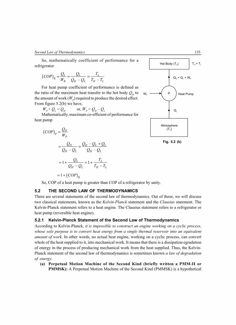
Second Law of Thermodynamics 135
So, mathematically coefficient of performance for arefrigerator
( )– –
L L LR
R H L H L
Q Q TCOPW Q Q T T
= = =
For heat pump coefficient of performance is defined asthe ratio of the maximum heat transfer to the hot body QH tothe amount of work (WP) required to produce the desired effect.From figure 5.2(b) we have,
WP + QL = QH or, WP = QH – QLMathematically, maximum co-efficient of performance for
heat pump
( ) HP
P
QCOPW
=
–
– –H H L L
H L H L
Q Q Q QQ Q Q Q
+= =
1 1– –L L
H L H L
Q TQ Q T T
= + = +
( )1 RCOP= +
So, COP of a heat pump is greater than COP of a refrigerator by unity.
5.2 THE SECOND LAW OF THERMODYNAMICSThere are several statements of the second law of thermodynamics. Out of these, we will discusstwo classical statements, known as the Kelvin-Planck statement and the Clausius statement. TheKelvin-Planck statement refers to a heat engine. The Clausius statement refers to a refrigerator orheat pump (reversible heat engine).
5.2.1 Kelvin-Planck Statement of the Second Law of ThermodynamicsAccording to Kelvin-Planck, it is impossible to construct an engine working on a cyclic process,whose sole purpose is to convert heat energy from a single thermal reservoir into an equivalentamount of work. In other words, no actual heat engine, working on a cyclic process, can convertwhole of the heat supplied to it, into mechanical work. It means that there is a dissipation egradationof energy in the process of producing mechanical work from the heat supplied. Thus, the Kelvin-Planck statement of the second law of thermodynamics is sometimes known a law of degradationof energy.
(a) Perpetual Motion Machine of the Second Kind (briefly written a PMM-II orPMMSK): A Perpetual Motion Machine of the Second Kind (PMMSK) is a hypothetical
Fig. 5.2 (b)
WP
Atmosphere(T )H
P Heat Pump
Q = Q + WH L P
QL
T > TH LHot Body (T )H

136 Mechanical Science-II
device (heat engine) which operates in cycle, absorbing energy as heat from a single thermalreservoir and delivering an equivalent amount of work. A schematic diagram of a perpetualmotion machine of the second kind is shown in figure 5.3. The Kelvin-Planck statement ofthe second law of thermodynamics never supports possibility of devising a PMMSK. So,PMMSK violates the second law of thermodynamics. But the PMMSK does not violate thefirst law of thermodynamics, because, the first law of thermodynamics does not put anyrestriction as to the fraction of heat drawn from a heat reservoir that can be converted towork. 100% efficient heat engine does not violate the first of thermodynamics.
(b) Actual Heat Engine: The statement implies that a heat engineE of the type shown in figure 5.3 which will receive heat (QH)from a high temperature (TH) reservoir, and convert itcompletely into work, is impossible. The only alternative isthat there must be at least one other low temperature (TL)reservoir to which heat QL must be rejected by the engine,because the second law of thermodynamics expresses thefact that the heat engine must reject heat to the low temperaturereservoir while drawing heat from the higher temperaturereservoir and this also implies that two heat reservoirs are anessential minimum for a heat engine. Accordingly, we obtain aschematic representation of a heat engine as shown in figure5.1. All heat engines must conform to this representation.
5.2.2 Clausius Statement of the Second Law ofThermodynamics
According to Clausius, it is impossible to construct a device (or self acting machine) working ina cyclic process, to transfer heat from a body at a lower temperature (TL) to a body at a highertemperature (TH) without the aid of an external agency. In otherwords, heat cannot flow itself from a cold body to a hot body withoutthe help of an external agency i.e., without the expenditure ofMechanical work.
(a) PMM-II: The device (reversible heat engine i.e., refrigeratoror heat pump) which violates the Clausius statement becauseno input work is supplied to the device to transfer heat froma cold body to a hot body is shown in figure 5.4. Such adevice is called perpetual motion machine of the second kind.
(b) 0 Reversible Heat Engine (Refrigerator/Heat Pump):The statement implies that refrigerator R or heat pump P ofthe type shown in figure 5.4 which will receive heat QL froma low temperature reservoir and transfer it to a hightemperature reservoir is impossible. The only alternative isthat there must be some work input (W). Accordingly, weobtain a schematic representation of refrigerator and heat Fig. 5.4
Hot Body (T )H
Refrigeratoror
Heat Pump
Cold Body(T )L
QL
R orP
QH
Fig. 5.3
High TemperatureRESERVOIR (T )H
HeatEngine
E
QH
W = QH

Second Law of Thermodynamics 137
pump as shown in figure 5.2(a) and (b). It is worth pointing out here that the devices infigure 5.2 represents a reversed heat engine since it comprises of all reversible processes.
5.3 EQUIVALENCE OF KELVIN-PLANCK AND CLAUSIUS OF SECOND LAW OFTHERMODYNAMICS
The Kelvin-Planck and Clausius statement of the second law of thermodynamics are, though appearto be different from each other, but these two statements are virtually equivalent in all respects. Theequivalence of Kelvin-Planck and Clausius statements can be proved, if it can be shown that theviolation of Kelvin-Planck statement implies the violation ofClausius statement and vice versa.
5.3.1 A Violation of Kelvin-Planck Statement Leadsto a Violation of Clausius Statement of theSecond Law of Thermodynamics
Consider a system as shown in figure 5.5. In this system, aheat engine having 100% thermal efficiency is violating theKelvin-Planck statement as it converts the heat energy (QL)from a single high temperature reservoir TH , into a equivalentamount of work i.e., W = QH. This work output of the heatengine can be used to drive a heat pump (reversible heatengine) which (W + QL) = QH + QL to a high temperaturereservoir at TH. If the combination of heat engine and areversible heat engine is considered as a single system, asshow in figure 5.5, then the result is a device that operates ina cycle and has no effect on the surroundings other than thetransfer of heat QL from a low temperature reservoir to a hightemperature reservoir, thus violating the Clausius statement.Hence, a violation of Kelvin-Planck statement leads to aviolation of Clausius statement.
5.3.2 A Violation of Clausius Statement Leads toa Violation of Kelvin-Planck Statement ofthe Second Law of Thermodynamics
Consider a system as shown in figure 5.6. In this system, aheat pump (PMM-II) is violating the Clausius statement asit transfers heat from a low temperature reservoir at TL to ahigh temperature reservoir at TH without any expenditureof work. Now let a heat engine, operating between the same heat reservoirs, receivesan amount of heat QH (as discharged by heat pump) fromthe high temperature reservoir at TH , does work WE = QH – QLand rejects an amount of heat QL to the low temperaturereservoir at TL. If the combination of the heat pump and the
Fig. 5.5
QH
High TemperatureReservoir (T )H
E PHeat Engine(PMM - II)
QL
Low TemperatureReservoir (T )L
W = QH
Q + QH L
HeatPump
QH
High TemperatureReservoir (T )H
P EHeat Pump(PMM - II)
QL
Low TemperatureReservoir (T )L
QH
HeatEngine
W = Q – QE H L
QL
Fig. 5.6

138 Mechanical Science-II
heat engine is considered as a single system, as shown in figure 5.6, then the result is a device thatoperates in a cycle whose sole effect is to remove heat at the rate of (QH – QL) and convert itcompletely into a equivalent amount of work, thus violating the Kelvin-Planck statement. Hence, aviolation of Clausius statement leads to a violation of Kelvin-Planck statement of the second law ofthermodynamics.
5.4 REVERSIBLE CYCLEA thermodynamically reversible cycle consists of reversibleprocesses. The process will be reversible when it isperformed in such fashion that the system remains at alltime infinitesimally near a state of thermodynamicequilibrium and at the end of process, both the system andthe surroundings may be restored to their initial state.Therefore, reversible processes are purely ideal. Inreversible process there are no dissipative effect, all thework done by the system during the performance of aprocess in one direction can be returned to the system duringthe reverse process. For example, consider a process inwhich the system (gas) is expanded from state 1 to state 2following the path 1–2 as shown in figure 5.7. If during thethermodynamic process 1–2 the work done on the systemby compressing is W1–2 and heat absorbed is Q1–2 , then byextracting heat Q1–2 from the system, we can bring thesystem and surrounding, back from state 2 to state 1following the same path 2–1, then the process issaid to be reversible process.
5.5 IRREVERSIBLE CYCLEA thermodynamic cycle will be irreversible, if any one of the process, constituting the cycle is anirreversible process. When heat and work are not completely restored back by reversing the process,then the process is known as irreversible or natural or real process. In an irreversible process, thereis a loss of heat due to friction, radiation or conduction. In actual practice most of the process areirreversible to some degree. In irreversible cycle, the initial condition are not restored at the end ofthe cycle.
5.6 REVERSIBILITY AND IRREVERSIBILITY OF THERMODYNAMIC PROCESS(a) Reversibility of Thermodynamic Process
Following are the conditions for reversibility of a cycle.1. The departure from equilibrium is infinitesimal i.e., dT → 0, dp → 0. Accordingly, all the
processes, taking place in the cycle of operation must be infinitely slowly, i.e., in a quasi-equilibrium manner.
2. The pressure and temperature of the working substance must not differ, appreciablyfrom those of the surroundings at any stage in the process.
Fig. 5.7
Pre
ssure
Volume
1
2

Second Law of Thermodynamics 139
3. The working parts of the engine must be friction free, because, there should not beany loss of heat due to friction.
4. There should be no loss of energy during the cycle of operation.
(b) Irreversibility of Thermodynamic ProcessThe main causes for the irreversibility are1. Due to lack of equilibrium during the process.2. Due to involvement of dissipative effects.3. Due to mechanical and fluid friction.4. Due to unrestricted expansion.5. Due to heat transfer with a finite
temperature difference.It is performed at a finite rate with finite potential
differences. If there is some friction involved in theprocess, it becomes irreversible, because frictionconverts the mechanical work into heat. This heatcannot supply back the same amount of mechanicalwork, which was consumed for its production.
5.7 CARNOT CYCLECarnot cycle is a reversible cycle. This cycle wasdevised by Carnot, in 1828, who was the first scientistto analyse the problem of the efficiency of a heatengine, disregarding its mechanical details. This cycle,operating between two heat reservoirs, consists of analternate series of two reversible isothermal and tworeversible adiabatic or isentropic processes. These cyclecan be operated either (i) as a vapour cycle (ii) or as agas cycle.
(i) Vapour Cycle: A cycle is defined as a vapourcycle when the processes involve change ofphase of working substance from liquid tovapour, and from vapour to liquid as shown infigure 5.8 on p-∀ diagram .
The Carnot vapour power cycle can be realised bya combination of flow processes as shown in figure 5.9.The cycle of operations is performed in different unitshaving a defined function. The substance, i.e., fluid,flows from one unit to the other unit in a steady flow. Inthe boiler isothermal process occurs, at temperature
Fig. 5.8
Pre
ssure
Volume
1 2
34
QH
QL
T = ConstantH
T = ConstantL
Q = 0 Q = 0
Fig. 5.9
Pump
Condenser
Boiler
PrimeMover
Win Wout
Heat Sink (T )L
Heat Source (T )H

140 Mechanical Science-II
TH, and water is transferred into steam. In the condenser steam is transferred into water at temperatureTL, the reversible adiabatic expansion operation takes place in the turbine or prime mover andreversible adiabatic compression takes place in the pump.
The Carnot efficiency is given by
CarnotH L
H
T – TT
η =
1 L
H
TT
= −
(ii) Gas Cycle: A cycle, in which the working substance remains a gas throughout, is referredto as a gas cycle, which is shown in figure 5.10.
In the Carnot cycle, the working substance (air supposed to behave like a perfect gas) is subjectedto a cyclic operation, consisting of two isothermal and two reversible adiabatic operations.
p1
p2
p4
p3
1
2
3
4
Iso. exp.
Isen.exp
.
Tem
pera
ture
Iso. comp.
Isen.co
mp
A
1
A
4
A
2
A
3
Volume
H.B.
C.B.
I.C. A
1 2
34
T3 = T4
T1 = T2
Entropy
S , S1 4 S2, S3
B A
Pre
ssure
Fig. 5.10
Here, air is enclosed in a cylinder in which frictionless piston A moves. The walls of the cylinderand piston are perfectly non-conductor of heat. The bottom B of the cylinder can be covered by aninsulating cap i.e., the engine is assumed to work between two sources of infinite heat capacity, oneat a higher temperature and other at a lower temperature. Four stages of the Carnot’s cycle are

Second Law of Thermodynamics 141
considered. The engine cylinder contains m kg of air at its original condition represented by point 1 onp-∀ diagram. At this point p1, T1 and ∀1 be the pressure, temperature and volume of the air.1. First Stage (Isothermal expansion)
The source (hot body H.B.) at a higher temperature is brought in contact with the bottom B ofthe cylinder. The air expands at constant temperature from ∀1 to ∀2 i.e., temperature T2 at point 2 isequal to T1. Isothermal expansion is represented by the curve 1–2 on p-∀ diagram. Heat supplied bythe hot body is totally absorbed by the air and is doing external work.
∴∴∴∴∴ Heat supplied = Work done
So, 1–2 1 1 lnQ p 2
1
∀= ∀ ∀
1 . lnmRT 2
1
∀= ∀
12.3 logmRT 2
1
∀= ∀
12.3 logrmRT=
Let 2
1
∀= =
∀r expansion ratio.
2. Second Stage (Reversible adiabatic expansion)The hot body is removed from the bottom of the cylinder and the insulating cap i.e., is brought in
contact. The air is now allowed to expand reversibly and adiabatically. Curve is represented by(2–3) on p-∀ diagram from ∀2 to ∀3. Temperature falls from T2 to T3 . No heat is absorbed orrejected by the air.∴ Decrease internal energy = Work done by adiabatic exp.
( ) ( )2 3 1 4– ––
– 1 – 1 – 1mR T T mR T Tp p2 2 3 3∀ ∀
= = =γ γ γ
3. Third Stage (Isothermal compression)Removing the insulating cap from the bottom and is brought the cold body (C.B) in its contact.
The air is compressed at constant temperature T3 from ∀3 to ∀4. Isothermal compression is representedby the curve (3–4) on p-∀ diagram. Heat is rejected to the cold body and is equal to the work doneon the air.
Heat rejected ( )3–4 3 3 3ln 2.3 logQ p mRT r3
4
∀= ∀ = ∀

142 Mechanical Science-II
–12
3
TT
γ3
2
∀ = ∀ ∵ and
–11
4
TT
γ4
1
∀= ∀
1–12
3
TT
γ3
2
∀∴ = ∀
and
1–11
4
TT
γ4
1
∀ = ∀
1 2 3 4andT T T T= =∵ ∴ 3 4
2 1
∀ ∀=∀ ∀
r3 2
4 1
∀ ∀∴ = = ∀ ∀
(4) Fourth Stage (Reversible adiabatic compression)Now the insulated cap is brought in contact with the bottom of the cylinder and the air is
allowed to be compressed reversibly and adiabatically represented by the curve (4–1) on p-∀ diagram.Temperature increases from T4 to T1. Since no heat is absorbed or rejected,
∴ Increase in internal energy = Work done
( )1 4––
– 1 – 1mR T Tp p1 1 4 4∀ ∀= =
γ γSo, decrease in internal energy during reversible adiabatic expansion (2–3) = increase in internal
energy during reversible adiabatic compression (4–1) Work done = Heat supplied – Heat rejected
∴ 1 32.3 log – 2.3 logW mRT r mRT r=
( )1 32.3 log –mR r T T=
∴ work done
heat suppliedη =
1 3 3
1 1
–1 –
T T TT T
= =
5.8 REVERSE CARNOT CYCLEThe Carnot cycle is a reversible cycle. If the processes of the Carnot power cycle are carried out inthe reverse order, it will become a refrigerator or heat pump cycle which is discussed before. It isthen referred to as reverse Carnot cycle.
5.9 CARNOT THEOREMIt states that, no heat engine working between two temperature can be more efficient than thereversible engine working between the same two temperature or Carnot engine (hypothetical),among all engines operating between two fixed temperature, is the most efficient.

Second Law of Thermodynamics 143
Multiple Choice Questions
1. In a power plant, Turbine work = 10,000 kJ, pump work = 10 kJ, heat supplied by boiler = 30,000 kJ.Thermal efficiency of the plant will be(a) 27% (b) 33.333%(c) 33.33% (d) 33.30%
2. A refrigerator and heat pump operate between the same temperature limits. If COP of the refrigeratoris 4, the COP of the pump would be(a) 3 (b) 5(c) 4 (d) cannot predict
3. Energy requirement to heat an enclosure fully insulated will be less(a) if heat pump is used for heating (b) if electric strip heater is used for heating(c) if steam is used for heating (d) if hot water is used for heating
4. It is impossible to construct an engine which while operating in a cycle produces no other effect toextract heat from a single reservoir and do equivalent amount of work.(a) this refers to Clausius statement (b) this refers to Kelvin-Planck statement(c) this refers to Carnot theorem (d) this does not refer to any of the above
5. Carnot cycle operates between temperature of 1000 K and 500 K. The Carnot efficiency will be 50%of working substance is(a) air (b) nitrogen(c) ammonia (d) any substance
6. Carnot cycle comprises(a) two isothermal processes and two isentropic processes(b) two constant volume processes and two isentropic processes(c) one constant volume, one constant pressure and two isentropic processes(d) two constant pressure and two isentropic processes
7. A heat engine is supplied with 800 kJ/sec of heat at 600 K and rejection take place at 300 K. Whichof the following results report a reversible cycle.(a) 200 kJ/sec are rejected (b) 400 kJ/sec are rejected(c) 100 kJ/sec are rejected (d) 500 kJ/sec are rejected
8. A heat engine is supplied with 800 kJ/sec of heat at 600 K and rejects 100 kJ/sec at 300 K. The datarefers to(a) reversible cycle (b) irreversible cycle(c) impossible cycle (d) none of the above
9. Equation TdS = dU + pd∀ can be applied to processes which are(a) only reversible (b) only irreversible(c) reversible or irreversible (d) none of the above
144 Mechanical Science-II
10. Change in entropy for isothermal process carried on a gas whose specific volume changes from V1 toV2 and pressure changes from p1 to p2 is given by
(a) ∆S = –Rln 2
1
∀∀
(b) ∆S = Rln 2
1
pp
(c) ∆S = –Rln 2
1
pp
(d) ∆S = –Rln 2
1
∀∀ + Rln
2
1
pp
11. Change in entropy for polytropic process is expressed as
(a) ∆S = Cv ––1
n γ γ
ln 2
1
TT
(b) ∆S = Cv ––1
n γ γ ln
2
1
TT
(c) ∆S = ––1
n RJ
γγ ln
2
1
TT
(c) ∆S = Cv ––1
n γ γ ln
2
1
∀∀
12. The polytropic index of expansion n in the equation pvn = c for constant volume process is(a) 1 (b) 1.4(c) α (d) 0 (zero)
13. The change of entropy of a closed system(a) is same for every process between two specified states(b) is not the same for every process between two specified states(c) is same only for isothermal process between two specified states(d) is the same only for reversible adiabatic process between two specified states.
14. The entropy of fixed amount of an ideal gas(a) decreases in every isothermal compression(b) increase in every isothermal compression(c) remains same in every isothermal compression(d) may increase or decrease in every isothermal compression.
15. The specific internal energy, enthalpy amd entropy of an ideal gas are(a) each function of temperature alone(b) each function of pressure alone(c) each function of volume alone(d) each of the above statements (a), (b) and (c) are false.
16. One of the Tds equation has the form(a) Tds = dh + vdp (b) Tds = dh – vdp(c) Tds = du – pdv (d) Tds = dh + pdv
17. The entropy of a fixed amount incompressible substance(a) decreases in every process in which temperature increases(b) remains same in every process in which temperature increases(c) increases in every process in which temperature increases(d) is not affected in the process by increase or decrease of temperature.
Second Law of Thermodynamics 145
18. A closed system undergoes a process in which the work done on the system in 5 kJ and heat transfer Qoccurs only at temperature Tb, the change in entropy for Q = 5 kJ and internally reversible process is:(a) positive (b) negative(c) zero (d) indeterminate.
19. Same as 18. For Q = 0 and internally reversible process. The change in entropy is(a) positive (b) negative(c) zero (d) indeterminate
20. Same as 18. For Q = –5 kJ and internally reversible the change in entropy is(a) positive (b) negative(c) zero (d) indeterminate
21. Same as 18. For Q = + 5 kJ and internal irreversibilities present the entropy chnage is(a) positive (b) negative(c) zero (d) indeterminate
22. Same as 18. For Q = 0 and internal irreversibilities present the entropy chnage is(a) positive (b) negative(c) zero (d) indeterminate
23. Same as 18. For Q = –5 kJ and internal irreversibilities present the entropy change is(a) positive (b) negative(c) zero (d) indeterminate
24. Which of the following statement is true(a) no process is allowed in which the entropies of both the system and surroundings increase(b) during a process, the entropy the system might decrease, while the entropy of surroundings
increases and conversely.(c) no process is allowed in which the entropies of both the system and the surroundings remain
unchanged.(d) a process can occur in which the entropies of both the system and the surrounding decrease.
Answers1. (d) 2. (b) 3. (a) 4. (b) 5. (d) 6. (a) 7. (b) 8. (c) 9. (c) 10. (c)11. (a) 12. (c) 13. (a) 14. (a) 15. (d) 16. (c) 17. (c) 18. (a) 19. (c) 20. (b)21. (a) 22. (a) 23. (d) 24. (b)
NUMERICAL EXAMPLES
EXAMPLE 1An engine works between the temperature limits of 1775 K and 375 K. What can be the maximum
thermal efficiency of the engine?

146 Mechanical Science-II
SOLUTION
Here, 1775 K, 375 KH LT T= =
max– 1775 – 375
0.18871775
H L
H
T TT
η = = =
EXAMPLE 2A heat engine receives heat @ 1500 kJ/min and gives an output of 8.2 kW. Determine thermal
efficiency and the rate of heat rejection.
SOLUTION
Here,3
3 31500 10 25 10 J/s, 8.2 10 J/s60HQ W×
= = × = ×
High TemperatureSOURCE (T )H
HeatEngine
E
Q = 1500 kJ/minH
Low TemperatureSINK (T )L
QL
W = 8.2 kW
Thermal efficiency th8.2
0.32825H
WQ
η = = =
Rate of heat rejection
( ) 3 3– 25 – 8.2 10 16.8 10 J/s 16.8 kJ/sL HQ Q W= = × = × =
EXAMPLE 3Find the coefficient of performance of heat transfer rate in the condenser
of a refrigerator in kJ/hr, which has a refrigeration capacity of 12,000 kJ/hr, whenpower input is 0.75 kW.
SOLUTION
Here, 12000 kJ/hrLQ =
0.75 60 60 kJ/hrRW = × ×
Hence, ( ) 12000COP 4.44
0.75 60 60L
RR
QW
= = =× ×
Condenser(T )H
Evaporator(T )L
QH
QL
R RefrigeratorWR

Second Law of Thermodynamics 147
Heat transfer rate
12000 0.75 60 60 14700 kJ/hrH LQ Q W= + = + × × =
EXAMPLE 4A house requires 2 × 10⁵ kJ/hr for heating in winter. Heat pump is used to absorb heat from a cold
air house. Work required to operate heat pump is 3 × 10⁴ kJ/hr. Determine heat abstracted from outside andcoefficient of performance.
SOLUTION
Heat requirement QH = 2 × 10⁵ kJ/hrWork required operating heat pump W = 3 × 10⁴ kJ/hrSo, heat abstracted from outside
5 4 4– 2 10 – 3 10 17 10 kJ/hrL HQ Q W= = × × = ×
( )5
5 42 10 6.66
– 2 10 – 17 10H
HH L
QCOP
Q Q×
= = =× ×
EXAMPLE 5A cyclic heat engine operates between a source temperature of 1000°C
and a sink temperature of 40°C. Find the least rate of heat rejection per kW netoutput of the engine.
SOLUTION
Here 1000 273 1273 K, 40 273 313 KH LT T= + = = + =For a reversible heat engine, the rate of heat rejection will be minimum for
max313
1 – 1 – 0.7541273
L
H
TT
η = = =
Again, net
max
11.326 kW
0.754HW
Q = = =η
EXAMPLE 6A reversible heat engine operates between two reservoirs at 600°C and 40°C. The engine drives a
reversible refrigerator, which operates, between reservoirs at 40°C and –20°C. The heat transfer to the engine2 MJ and the net work output of the combined engine and refrigerator plant is 360 kJ. Find the heat transfer tothe refrigerant and the net heat transfer at the reservoir at 40°C. Also find these values if the efficiency of theheat engine and COP of the refrigerator are each 40% of their maximum possible values.
SOLUTION
(i) Here 1 1600 273 873 K, – 20 273 253 K, 40 273 313 K.H H L LT T T T= + = = + = = = + =Let QH = 2000 kJ is the heat transfer to the engine and QH1 is the heat transfer to the refrigerant. So, maximum
efficiency of the heat engine max313
1 – 1 – 0.6415873
L
H
TT
η = = =
High emperatureSOURCE (
TT = 1273 K)H
QH
QL
Low emperatureSINK (
TT = 313 K)L
HeatEngine
EW

148 Mechanical Science-II
1st SourceT = 873 KH
2nd SourceT = 253 KH1
QH QH1
Heat Engine Refrigerator
W
SinkT = T = 313 KL L1
W Q QE H L= –
Q Q WL H E= – Q Q WL H R1 1= +
Again, work done max 2000 0.6415 1283 kJ.E HW Q= × η = × =Since the net work output of the combined heat engine and refrigerator plant is W = WE – WR = 360 kJ, workrequired for the refrigerator WR = WE – W = 1283 – 360 = 923 kJ.We know maximum COP of the refrigerator
( ) 1max
1 1
253COP 4.217– 313 – 253H
H L
TT T
= = =
Again, ( ) 1 1ma
1 1COP
–H H
xH L R
Q QQ Q W
= =
⇒ 1 4.217 923 3892.3 kJHQ = × =
Here, 1 1 3892.3 923 4815.3 kJL H RQ Q W= + = + =
And – 2000 – 1283 717 kJL H EQ Q W= = =
Hence, net heat transfer to the reservoir at 40°C is 1 717 4815.3 5532.3 kJL LQ Q+ = + =(ii) When the efficiency of the heat engine and COP of the refrigerator are each 40% of their maximumpossible values, actual 0.4 0.6415 0.2566η = × =Work done by the engine actual 2000 0.2566 513.2 kJE HW Q= × η = × =Work required for the refrigerator – 513.2 – 360 153.2 kJR EW W W= = =
Now ( )actualCOP 0.4 4.217 1.6868= × =So, heat transfer to the refrigerant 1 1.6868 153.2 258.4 kJHQ = × =
Here, 1 1 258.4 153.2 411.6 kJL H RQ Q W= + = + = and
– 2000 – 411.6 1588.4 kJL H EQ Q W= = =

Second Law of Thermodynamics 149
Hence, net heat transfer to the reservoir at 40°C is
1 1588.4 411.6 2000 kJL LQ Q+ = + =
EXAMPLE 7A Carnot engine working between 650 K and 310 K produce 150 kJ of work. Find the thermal
efficiency and heat added during the process.
SOLUTION
Efficiency 310
1 – 1 – 0.523650
L
H
TT
η = = =
Heat added 150 286.8 kJ
0.523WQ = = =η
EXAMPLE 8A Carnot engine is operated between two reservoirs at TH and TH1. The work output of the engine
is 0.6 times the heat rejected. The difference in temperature between the source and the sink is 200°C. Calculatethe thermal efficiency, source temperature and sink temperature.
SOLUTION
Here, 1– 10.6 H LW Q= and 1– 200 CH HT T = °
Thermal efficiency 1– 1
1– 1 1– 1 1– 1
0.6 0.60.375
0.6 1.6H L
H L H L H L
QWW Q Q Q
η = = = =+ +
Again, 1– 200H H
H H
T TT T
η = =
⇒ 200
533.3 K 260.3 C0.375HT = = = °
⇒ 1 260.3 – 200 60.3 CHT = = °
EXAMPLE 9A Carnot cycle has an efficiency of 32%. Assuming that the lower temperature is kept constant,
determine the % increase on the upper temperature of the cycle if the cycle efficiency is raised to 48%.
SOLUTION
Here, 1 – 0.32L
H
TT
η = =
⇒ 1 – 0.32 0.68L
H
TT
= =
When the efficiency is raised to 48%, 1 – 0.48 0.52LTT
= =

150 Mechanical Science-II
So, 0.68
1.30770.52H
TT
= =
or, 1 0.30771
H
H
T xT
+ +=
⇒ 0.3077x =The % increase on the upper temperature of the cycle is 30.77
EXAMPLE 10A vessel of 2.5 m3 capacity contains 1 kg mole of N2 at 100°C. If the gas is cooled to 30°C, calculate
the change in specific entropy.
SOLUTION
The ratio of specific heats is 1.4 and 1 kg-mole of N2 is 28 kg.Here 100 273 373 K, 30 273 303 KH LT T= + = = + =
Now,8.314
– 0.29728
up v
RC C R
M= = = =
⇒ 1.4 – 0.297v vC C =
⇒ 0.74 kJ/kgKvC =
So, 303
– ln 1.0 0.74 ln – 0.1536 kJ/kgK373
LH L v
H
TS S mC
T = = × =
The negative sign indicates decrease in entropy.
EXAMPLE 11300 kJ/s heat is supplied from a constant fixed source of 290ºC to a heat engine. The heat rejection
takes place at 8.5ºC. The following results were obtained: (i) 215 kJ/s heat rejected (ii) 150 kJ/s heat rejected(iii) 75 kJ/s heat rejected. Determine these cycles are reversible or irreversible.SOLUTION
Applying Clausius inequality to all these processes
(i) 300 215
– – 0.2309 0290 273 8.5 273
QT
δ= = <
+ +∑Hence, the cycle is irreversible.
(ii) 300 150
– 0290 273 8.5 273
QT
δ= =
+ +∑Hence, the cycle is reversible.
(iii) 300 75
– 0.2664 0290 273 8.5 273
QT
δ= = >
+ +∑Hence, the cycle is impossible.

Second Law of Thermodynamics 151
EXAMPLE 121 kg of air is heated on constant volume from 100°C to 400°C. If Cv = 0.7186 kJ/kgK, determine the
change in entropy in the air.
SOLUTION
Change in entropy of air
400 273
100 273
6731 0.7186 ln 0.4241 kJ/K
373
H
L
T
vT
dQ dTS mCT T
+
+
∆ = = = × = ∫ ∫
EXAMPLE 13A Carnot power cycle operates between 1200 K and 300 K. If 4.8 MJ of heat is supplied to the cycle,
determine the heat rejected and the change in entropy for this rejection process.
SOLUTION
For Carnot cycle, H L
H L
Q QT T
=
Hence, 300
4.8 1.2 MJ1200
LL H
H
TQ Q
T= = =
Change in entropy for the process of heat rejection
31.2 10 0.4 kJ/K
300L
H
QS
T×
∆ = = = .
EXAMPLE 14A heat engine receives reversible 420 kJ/cycle heat from a source at 327°C and rejects heat
reversible to a sink at 27°C. There are no other heat transfers. For each of the three hypothetical amount heat
rejection as (i) 210 kJ/cycle (ii) 105 kJ/cycle (iii) 315 kJ/cycle compute the cyclic integral QTδ
in each case. Showwhich one is reversible, irreversible or impossible.SOLUTION
Applying Clausius inequality to all these processes
(i)420 210
– 0327 273 27 273
QT
δ= =
+ +∑Hence, the cycle is reversible.
(ii)420 105
– 0.35 0327 273 27 273
QT
δ= = >
+ +∑Hence, the cycle is impossible.
(iii)420 315
– 0.35 0327 273 27 273
QT
δ= = − <
+ +∑Hence, the cycle is irreversible.
Low TemperatureSINK (T = 300 K)L
QL
E
QH = 4.8 MJ
High TemperatureSOURCE (T = 1200 K)H
WHeatEngine

152 Mechanical Science-II
EXAMPLE 15Two bodies each of equal mass m and equal heat capacity C are at temperature T1 and T2 respectively
and T1 > T2. If the first body is used a source of heat for reversible engine and the second as the sink, show that
the maximum work obtainable from such arrangement is ( )21 2– .mC T T
SOLUTION
Let the common temperature of the two bodies be Tc. Maximum work is obtained when the engine operatesalong a reversible cycle. In that case, entropy change of the composite system formed by the two bodies is zero.Thus,
1 2ln ln 0c cT T
mC mCT T
+ =
⇒ 2
1 2ln 0cT
mCT T
=
⇒ 2
1 21cT
T T=
⇒ 1 2cT T T=Now the work done
Wnet = ( ) ( )1 2– – –c cmC T T mC T T
= ( ) ( )1 1 2 1 2 2– – –mC T T T T T T
= ( )21 2 1 2 1 2– 2 –mC T T T T mC T T + =
EXAMPLE 16A Carnot heat engine draws heat from a reservoir at temperature TA and rejects heat to another
reservoir at temperature TB. The Carnot forward cycle againdrives a Carnot reversed cycle engine or Carnot refrigerator,which absorbs heat from reservoir at temperature TC andrejects heat to reservoir at temperature TB. Derive anexpression for the ratio of heat absorbed from reservoir attemperature TC to heat drawn from reservoir at temperatureTA. If TA is 500 K and TC is 250 K, determine the temperature TB,such that heat supplied to engine QA is equal to heat absorbedby refrigerator QC. Determine efficiency and COP of Carnotrefrigerator.
SOLUTION
carnot
engine– –A B A B
A A A
WQ Q T TQ T Q
η = = =
TC TA
TB
QC QA
Q1AQ2B
QA– Q1B
WCarnotCarnotRefrigerator
CarnotEngine
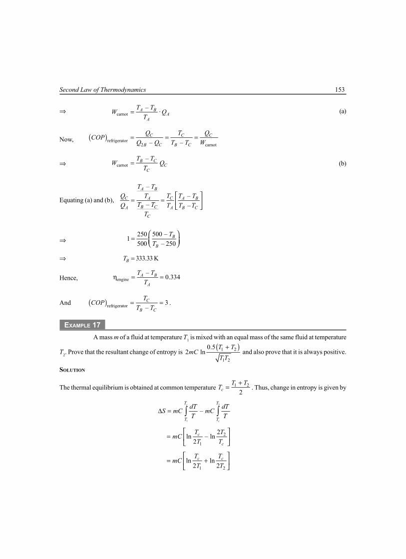
Second Law of Thermodynamics 153
⇒ carnot– .A B
AA
T TW Q
T= (a)
Now, ( )refrigerator2 carnot– –
C C C
B C B C
Q T QCOP
Q Q T T W= = =
⇒ carnot–B C
CC
T TW Q
T= (b)
Equating (a) and (b),
––
– –
A B
C CA A B
B CA A B C
C
T TQ TT T T
T TQ T T TT
= =
⇒ 500 –2501
500 – 250B
B
TT
=
⇒ 333.33 KBT =
Hence, engine–
0.334A B
A
T TT
η = =
And ( )refrigerator 3–C
B C
TCOP
T T= = .
EXAMPLE 17A mass m of a fluid at temperature T1 is mixed with an equal mass of the same fluid at temperature
T2. Prove that the resultant change of entropy is ( )1 2
1 2
0.52 ln
T TmC
T T+
and also prove that it is always positive.
SOLUTION
The thermal equilibrium is obtained at common temperature 1 2
2cT T
T+
= . Thus, change in entropy is given by
2
1
–c
c
T T
T T
dT dTS mC mCT T
∆ = ∫ ∫
2
1
2ln – ln
2c
c
T TmCT T
=
1 2
ln ln2 2
c cT TmC
T T
= +
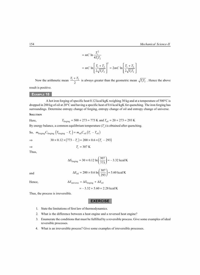
154 Mechanical Science-II
2
1 2ln
4cT
mCT T
=
21 2 1 2
1 2 1 2
ln 2 ln2 2T T T T
mC mCT T T T
+ += =
Now the arithmetic mean 1 2
2T T+
is always greater than the geometric mean 1 2T T . Hence the above
result is positive.
EXAMPLE 18A hot iron forging of specific heat 0.12 kcal/kgK weighing 30 kg and at a temperature of 500°C is
dropped in 200 kg of oil at 20°C and having a specific heat of 0.6 kcal/kgK for quenching. The iron forging hassurroundings. Determine entropy change of forging, entropy change of oil and entropy change of universe.
SOLUTION
Here, forging oil500 273 773 K and 20 273 293 KT T= + = = + =
By energy balance, a common equilibrium temperature (Tc) is obtained after quenching.
So, ( ) ( )forging forging forging oil oil oil– –c cm C T T m C T T=
⇒ ( ) ( )30 0.12 773 – 200 0.6 – 293c cT T× × = × ×
⇒ 307 KcT =Thus,
forging30730 0.12 ln – 3.32 kcal/K773
S ∆ = × =
and oil307200 0.6 ln 5.60 kcal/K293
S ∆ = × =
Hence, universe forging oilS S S∆ = ∆ + ∆
– 3.32 5.60 2.28 kcal/K= + =Thus, the process is irreversible.
EXERCISE
1. State the limitations of first law of thermodynamics.2. What is the difference between a heat engine and a reversed heat engine?3. Enumerate the conditions that must be fulfilled by a reversible process. Give some examples of ideal
reversible processes.4. What is an irreversible process? Give some examples of irreversible processes.

Second Law of Thermodynamics 155
5. Narrate the propositions of Clausius statement and Kelvin-Planck statement.6. Define heat engine, refrigerator and heat pump.7. What is the perpetual motion machine of the second kind?8. What is the efficiency of heat engine?9. What is COP of the reversible heat engine?
10. Derive the expression for COP of heat pump and refrigerator. Establish the relation between COP ofpump and COP of refrigerator.
11. A heat engine is supplied with 278 kJ/s of heat at a constant fixed temperature of 283°C and the heatrejection takes places at 5°C. Then results reported as: (i) 208 kJ/s rejected (ii) 139 kJ/s rejected(iii) 70 kJ/s rejected. Classify which of the results report a reversible cycle or irreversible cycle orimpossible cycle.
12. Source A can supply energy @11 MJ/min at 320°C. A second source B can supply energy@110 MJ/min at 68°C. Which source would you choose to supply energy to an ideal reversible enginethat is to produce large amount of power if the temperature of the surroundings is 40°C.
13. A domestic food freezer maintains a temperature of –15°C. The ambient air temperature is 30°C. If heatleaks into the freezer continuously @1.75 kJ/s, what will be the least power necessary to pump thisheat out continuously.
14. A heat engine supplied heat @1700 kJ/min and gives an output of 9 kW. Determine the thermalefficiency and rate of heat rejection.
15. A fish freezing plant requires 50 tons of refrigerant. The freezing temperature is –40°C while theambient temperature is 35°C. If the performance of the plant is 15% of the theoretical reversedCarnot cycle working within the same temperature limits, calculate the power required.

This pageintentionally left
blank

6.1 INTRODUCTIONWhen first law of thermodynamics was applied for thermodynamic processes, the existence of aproperty, internal energy, was found. This is called the corollary 1 of the First Law ofThermodynamics. Similarly, when second law of thermodynamics applied to thermodynamicprocesses, the second law also leads to the definition of a new property, known as entropy. So, if thefirst law is said to be the law of internal energy, then second law may be stated to be the law ofentropy. The term ‘entropy’ was first introduced by Clausius. Entropy means transformation. It isan important thermodynamic property of a working substance, which increases with addition of heatand decreases with its removal. As a matter of fact, it is comparatively more easy to define changeof entropy than to define the term entropy. When change of entropy (dS) is multiplied by theabsolute temperature (T ), gives the heat (δQ) absorbed or rejected by the working substance.
Mathematically, heat absorbed by the working substance
QQ TdS dST
δδ = ∴ = (6.1)
So change of entropy is the change of heat per unit absolute temperature.Entropy may be defined as following:Entropy is function of a quantity of heat which shows the possibility of conversion of that
heat into work. The increase in entropy is small when heat is added at high temperature and isgreater when heat addition is at low temperature. Thus for minimum entropy there is maximumavailability for conversion into work, for maximum entropy, there is a minimum availability forconversion into work.
It may also be defined as the thermodynamic property of a substance which remains constantwhen substance is expanded or expressed reversible adiabatically in a cylinder.
6.2 IMPORTANCE OF ENTROPYIn a reversible Carnot cycle, the maximum possible efficiency obtainable is given by
max–H L
H
T TT
η = (a)
6CHAPTER
ENTROPY

158 Mechanical Science-II
where TH is highest absolute temperature and TL is lowest absolute temperature. Again, in generalefficiency is given by
maxη = maximum work obtainedheat applied or absorbed
= WQ
δδ
or, Wδ = max Qη × δ
= H L
H
T T QT
−× δ
(6.2)
For one degree temperature drop, the above expression may be written as
Wδ = where 1H LQ T TTδ
− =
= dS= change in entropy (6.3)
It can be understood from above equation that1. The maximum amount of work obtained per degree drop in temperature is equal to
change of entropy i.e., change of entropy is equal to the maximum work for one degreetemperature drop.
2. The change in entropy may be regarded as a measure of the rate of availability orunavailability of heat for temperature into work.
3. The increase in entropy is obtained from a given quantity of heat at low temperature.
6.3 UNITS OF ENTROPYWe know
dS = QTδ
So unit of entropy depends upon the unit of heat and the absolute temperature. If δQ is expressedin kJ and T in K, then unit of entropy kJ/K.
6.4 CLAUSIUS THEOREM
Clausius theorem state that “the cyclic integral QT
δ for a reversible cycle is equal to zero”
Mathematically
R
QTδ∫ = 0
The letter R emphasizes the fact that the equation is valid only for reversible cycle. It can beproved as below.

Entropy 159
Consider a system undergoing a reversible process1–b–2 from a equilibrium state 1 to another equilibrium statepoint 2, by the reversible path is shown in figure 6.1. Let areversible adiabatic 1–a be drawn through 1 and anotherreversible adiabalic 2–c be drawn through 2, then reversibleisothermal a–b–c is drawn in such a way that the areaenclosed by 1–a–b and b–c–2 are equal on a p-∀ diagram.
Then the actual reversible process 1–b–2 can bereplaced by the combination of the above processes,resulting in the overall process 1–a–b–c–2. The process1–b–2 and 1–a–b–c–2 are equivalent if and only if theheat and work interaction are identical for both theprocesses. Applying the first law of thermodynamics forthe two processes,
1. For the process 1–b–2,U2 – U1 = Q1–b–2 – W1–b–2 (a)
2. For the process 1–a–b–c–2,U2 – U1 = Q1–a–b–c–2 – W1–a–b–c–2
= Q1–a + Qa–b–c + Qc–2 – W1–a–b–c–2
= Qa–b–c – W1–a–b–c–2 (b)Since 1-a and c-2 are reversible adiabatic process, Q1–a = 0 and Qc-2 = 0Now consider the cycle 1–a–b–c–2–b–1. The net work done in this cycle is zero since the area
enclosed by 1–a–b is equal to the area enclosed by b–c–2 on a p–∀ diagram in figure 6.1
i.e., ∫ δW = W 1–a–b–c–2 + W2–b–1 = 0
or, W1–a–b–c–2 = –W2–b–1
= W1–b–2 (c)Comparing the equation (a) and (c), we have
Q1–a–b–c–2 – W1–a–b–c–2 = Qa–b–c – W1–b–2
= Q1–b–2 – W1–b–2
∴ Q1–a–b–c–2 = Qa–b–c = Q1–b–2
That is, heat transferred along in the processes 1–b–2 is equal to the heat transferred in theprocesses 1–a–b–c–2. So, the process 1–b–2 can be replaced by the process 1–a–b–c–2.
Any reversible path may be substituted by a reversible zigzag path, between the same end states,consisting of a reversible adiabatic followed by a reversible isothermal and then by a reversibleadiabatic, such that the heat transferred during the isothermal processes is same as that transferredduring the original process.
a
p
Isothermal
2b
1
c
Adiabatic
Fig. 6.1

160 Mechanical Science-II
Consider a system which undergoes the cyclic change asshown in figure 6.2. Now draw a family of closely spaced adiabaticline similar to a–3 and 2–f covering the entire cycle. Then join theadjacent adiabatic lines d–e–f as shown in figure 6.2, such thatthe area of 1–a–b = area of b–c–2 and area of 3–d–e = area ofe–f–4.
Thus the segments 1–b–2 and 3–e–4 of the reversible cycleare replaced by 1–a–b–c–2 and 3–d–e–f–4, respectively. Now thedifferential cycle a–b–c–4–f–e–d–a is a Carnot cycle. Thus theoriginal cycle can be transformed into a combination of severaldifferential Carnot cycles. If the adiabatics are close to one anotherand number of Carnot cycles are large, the saw-toothed zig-zag linewill coincide with the original cycle.
For the elemental cycle a–d–f–c, dQ1 heat is absorbed reversibly at T1 and δQ2, heat is rejectedreversibly at T2
∴1 2
1 2
Q QT T
δ δ= (6.5)
Heat supply is taken as positive and heat rejected as negative
So,1 2
1 20Q Q
T Tδ δ
+ =
If similar equations are written from all the elemental Carnot cycles, then for whole originalcycle
31 2
1 2 3
... 0QQ Q
T T Tδδ δ
+ + + =
0QTδ =∑
or for a differential Carnot cycles
0QT
δ =∫ [ for reversible cycle]
This is known as Clausius theorem.For reversible cycle the thermal efficiency is given by
1 2 1 2
th1 1
Q Q T TQ T− −
η = = (6.6)
But for an irreversible engine according to Carnot theorem, the thermal efficiency is
1 2 1 2
1 1
Q Q T TQ T− −
<
or 2 2
1 11 – 1 –Q T
Q T<
Fig. 6.2
2a
c
4
fd
b
e3
1
p

Entropy 161
or 2 2
1 1
Q TQ T
>
or 2 1
2 1
Q QT T
>
or 1 2
1 2
Q QT T
<
or 1 2
1 2– 0Q Q
T T<
Therefore, in differential form, for irreversible engine
0.QT
δ <∫ (6.7)
6.5 ENTROPY— A POINT FUNCTION OR A PROPERTY OF A SYSTEMLet a system shown in Figure 6.3 be taken from an initialequilibrium state 1 to a final equilibrium state 2 by thereversible path A and the system is brought back from 2to 1 by another reversible path B. Then the two path Aand B together constitute a reversible cycle. From Clasiustheorem, we have
,
0A B
QT
δ=∫
[It can be replaced as the sum of two integrals one forpath A and other for path B]
∴2
1
OA
QT
δ∫ + 1
2
O 0B
QT
δ =∫
or2
1
OA
QT
δ∫ = 1
2
– OB
QTδ∫
Path B is a reversible path,2
1
OA
QT
δ∫ = 2
1
OB
QT
δ∫
Since path A and B represent any two reversible paths, 2
1
O QT
δ∫ is independent of the path.
So 2
1
O QT
δ∫ is a property, is a point function,and its values depend on initial and final points only, not on
the path
Y
X
B
A
1
2
Fig. 6.3

162 Mechanical Science-II
∴ 2
1
O QT
δ∫ = S2 – S1 = dS (change of entropy) (6.8)
6.6 CLAUSIUS INEQUALITYThe Clausius inequality states that when a closed system undergoes a cyclic process, the cyclic
integral of QTδ
is less than zero (negative) for irreversible cyclic process and equal to zero fora reversible cyclic process.
∴ 0QT
δ <∫ ( for irreversible process)
0QT
δ =∫ ( for reversible process)
Combining the above two equation, we have
0QT
δ ≤∫ (6.9)
which is called Clausius inequality. It is already proved in art.6.4. The Clausius inequality not onlygives mechanical expression to the 2nd law of thermodynamics, but it also gives the quantitativemeasure of irreversibility of the system. For example,
For irreversible cyclic process 0QT
δ <∫
So, it may be written as 0Q mTδ + =∫
where m represents the amount by which the given cyclic process is irreversible.
When m is equal to zero, that is 0QT
δ >∫ is impossible, because it voilates the 2nd law of
thermodynamics.
6.7 PRINCIPLE OF INCREASE OF ENTROPYThe equation for the Clausius inequality is written as
0QT
δ ≤∫ (a)
Again we know the change in entropyQdST
δ=
Being a thermodynamic property, the cyclic-integral of a entropy is zero, that is 0dS =∫Therefore equation (a) may be written as
Q dST
δ ≤∫ ∫

Entropy 163
T2
T
T1
2
S2S1
ds
A
1
Fig. 6.4
∴Q dST
δ ≤
∴ QdST
δ≥ (b)
When the process is reversible, thenQdST
δ= (6.10)
and when the process is irreversible, thenQdST
δ> (6.11)
In case of isolated system δQ = 0, if we apply the equation (b) in isolated system the equation(b) will be
dS ≥ 0,when dS = 0, for reversible cyclic process, S = Constant
Now for an irreversible cyclic processdS > 0
Since, in actual practice, all processes are irreversible, therefore the entropy of such system likeuniverse goes on increasing. This is known as the principle of increase of entropy.
6.8 ENTROPY AND TEMPERATURE RELATIONEntropy is the thermodynamic property of a working substance that increases with the increase oftemperature and decreases with decrease of temperature.if δQ = heat absorbed,
dS = increase in entropyT = absolute temperature
∴ δQ = T.dSConsider the heating of a working substance by a
reversible process as shown in the figure 6.4 by a curvefrom 1 to 2 in temperature-entropy diagram.
At a small quantity of heat is supplied δQ,δQ = T .dS
= area under curve during change of entropy
∵2 2
1 1
.Q T dSδ =∫ ∫2 2
1 1
QdST
δ=∫ ∫ (6.12)

164 Mechanical Science-II
So, total area under the T-S diagram of any thermodynamic process represents the heat absorbedor heat rejected.
As QT
δ∫ is same for all reversible paths between states 1 and 2 it is independent of the path and
is a function of end states only.
6.9 GENERAL EXPRESSION FOR CHANGE OF ENTROPY OF A PERFECT GASConsider a certain quantity of perfect gas heated by any thermodynamic process.
Let, m = mass of the gasp1 and p2 = initial and final pressure
∀1 and ∀2 = initial and final volumeT1 and T2 = initial and final absolute temperature
(i) In terms of volume and absolute temperatureδQ = dU + δW
= m.CV.dT + pd∀
∴QTδ
= . .v
dT dm C pT T
∀+
As, p∀ = mRTpT =
mR∀
∴ dS = . .v
dT mRmC dT
+ ∀∀
Q dST
δ = ∵
Integrating within limits,2
1
S
S
dS∫ = 2 2
1 1
.T v
vT v
dT dmC mRT
∀+∀∫ ∫
or, (S2 – S1) = mCv (ln T2 – ln T1) + mR (ln ∀2 – ln ∀1)
2 2
1 1
. .2.3 log logvTm C RT
∀= + ∀
( )2 2
1 1
.2.3 log – logv p vTm C C CT
∀= + ∀ (ii) In terms of pressure and absolute temperature
We know 1 1
1
pT∀
= 2 2
2
pT∀
∴ 2
1
∀∀
= 1 2
2 1
.p Tp T

Entropy 165
Proceeding in the similar way,
( ) 2 1 22 1
1 2 1
. . .– ln lnvT p TS S mC mRT p T
= +
2 1 2
1 2 1
. .ln ln lnvT p TmC mR mRT p T
= + +
[ ]2 1
1 2ln lnv
T pm C R mRT p
= + +
2 1
1 2
. .2.3 log logpT pm C RT p
= +
2 1
1 2
. .2.3 log logpT pm C RT p
= +
(iii) In terms of pressure and volume
We know, 1 1 2 2
1 2
p pT T∀ ∀
=
∴ 2 2 2
1 1 1
.T pT p
∀=
∀Proceeding in the similar fashion
( ) 2 2 22 1
1 1 1
. . .– ln lnvpS S mC mRp
∀ ∀= + ∀ ∀
2 2 2
1 1 1
. .ln ln lnv vpmC mC mRp
∀ ∀= + + ∀ ∀
( )2 2
1 1
. .ln lnv vpmC m C Rp
∀= + + ∀
2 2
1 1
. .ln lnv ppmC m Cp
∀= + ∀
2 2
1 1
. .2.3 log logv ppm C Cp
∀= + ∀
6.10 CHANGE OF ENTROPY OF PERFECT GAS DURING VARIOUSTHERMODYNAMIC PROCESS
(a) Constant volume process (Isochoric process):A certain quantity of gas is heated at constant volume, wherep1 = Initial pressure, T1 = Initial temperature
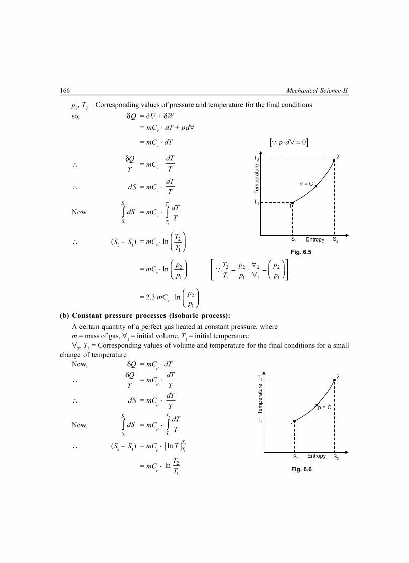
166 Mechanical Science-II
p2, T2 = Corresponding values of pressure and temperature for the final conditionsso, δQ = dU + δW
= mCv . dT + pd∀
= mCv . dT [ ]. 0p d∀ =∵
∴QTδ
= mCv . dTT
∴ dS = mCv . dTT
Now2
1
S
S
dS∫ = mCv . 2
1
T
T
dTT∫
∴ (S2 – S1) = mCv . ln
2
1
TT
= mCv . ln
2
1
pp
2 2 2 2
1 1 1 1
.T p pT p p
∀= = ∀
∵
= 2.3 mCv . ln 2
1
pp
(b) Constant pressure processes (Isobaric process):A certain quantity of a perfect gas heated at constant pressure, wherem = mass of gas, ∀1 = initial volume, T1 = initial temperature∀2, T2 = Corresponding values of volume and temperature for the final conditions for a small
change of temperatureNow, δQ = mCp
. dT
∴QTδ
= mCp . dTT
∴ dS = mCp . dTT
Now,2
1
S
S
dS∫ = mCp . 2
1
T
T
dTT∫
∴ (S2 – S1) = mCp . [ ] 2
1ln T
TT
= mCp . 2
1ln T
T
Fig. 6.5
T22
EntropyS1 S2
Tem
pera
ture
T11
= C
Fig. 6.6
T22
EntropyS1 S2
Tem
pera
ture
T11
p = C

Entropy 167
= 2.3 mCp . log 2
1
TT
= 2.3 mCp . log
2
1
∀ ∀
2 2
1 1
TT
∀= ∀
∵
6.11 IRREVERSIBILITYThe actual work which a system does is always less than the idealized reversible work, and thedifference between the two is called the irreversibility of the process.
If, I = the irreversibility,W = the actual workWmax = the idealized reversible worker maximum work.
Then, Irreversibility, I = Wmax – WThis is also sometimes referred to a degradation or dissipation.The irreversibility in (i) non-flow process and (ii) steady flow-process is discussed below
(i) For a non-flow processIn non-flow process between the equilibrium states, when the system exchanges heat only with
environment, irreversibility for unit mass,i = wmax – wi = [(u1 – u2) – T0 (S1 – S2)] – [(u – u2) + q]
= ( )0 2 1– –T S S q
= ( ) ( )0 0system surroundingT S T S∆ + ∆
So, i ≥ 0(ii) For steady flow-process
i = wmax – w
= 2 21 2
1 1 2 2–2 2
C Cb gz b gz + + + +
2 21 2
1 1 2 2– –2 2
C Ch gz h gz q + + + + +
= ( )0 2 1– –T S S q
= ( ) ( )0 0system surroundingT S T S∆ + ∆
The same expression for irreversibility applies to both flow and non-flow process.

168 Mechanical Science-II
Multiple Choice Questions
1. Second law of thermodynamics defines(a) heat (b) work (c) enthalpy(d) entropy (e) internal energy
2. For a reversible adiabatic process, the change in entropy is(a) zero (b) minimum (c) maximum(d) infinite (c) unity
3. For any reversible process, the change in entropy of the system and surrounding is(a) zero (b) unity (c) negative(d) positive (e) infinite
4. For any irreversible process the net entropy change is(a) zero (b) positive (c) negative(d) infinite (e) unity
5. The processes of a Carnot cycle are(a) two adiabatics and two constant volume(b) one constant volume and one constant pressure and two isentropics(c) two adiabatics and two isothermals(d) two constant volumes and two isothermals(e) two isothermals and two isentropics
6. Isotropic flow is(a) irreversible adiabatic flow (b) ideal fluid flow (c) perfect gas flow(d) frictionless reversible flow (e) reversible adiabatic flow
7. In a Carnot engine, when the working substance gives heat to the sink(a) the temperature of the sink increases(b) the temperature of the sink remains same(c) the temperature of the source decreases(d) the temperature of both the sink and the source decrease(e) changes depend on the operating conditions
8. If the temperature of the source is increased, the efficiency of a Carnot engine(a) decreases (b) increases (c) does not change(d) will be equal to the efficiency (e) depends on other factors
of a practical engine
9. The efficiency of an ideal carnot engine depends on(a) working substance(b) on the temperature of the source only(c) on the temperature of the sink only(d) on the temperature of both the source and the sink(e) on the construction of engine
Entropy 169
10. The efficiency of a carnot engine using on ideal gas as the working substance is
(a) 1 2
1
–T TT
(b) 1
1 2–T
T T(c) 1 2
1 2–T T
T T
(d) 1 2
1 2
–T TT T
(e) ( )( )
2 1 2
1 1 2
–T T TT T T+
11. In a reversible cycle, the entropy of the system(a) increases (b) decreases (c) does not change(d) first increases and then decreases(e) depends on the properties of working substance
12. A frictionless heat engine can be 100% efficient only if its exhaust temperature is:(a) equal to its input temperature (b) less than its input temperature(c) 0°C (d) 0 K(e) –100°C
13. Kelvin-Planck’s law deals with(a) conservation of energy (b) conservation of heat(c) conservation of mass (d) conservation of heat into work(e) conservation of work into heat
14. Which of the following statements is correct according to Clausius statements of second law ofthermodynamics?(a) it is impossible to transfer heat from a body at a lower temperature to a body at a higher temperature(b) it is impossible to transfer heat from a body at a lower temperature to a body at a higher temperature
without the aid of an external source(c) it is possible to transfer heat from a body at a lower temperature to a body at a higher temperature
by using refrigeration cycle(d) none of the above
15. According to Kelvin Planck’s statement of second law of temperature(a) it is impossible to construct an engine working on a cyclic process, whose sole purpose is to
convert heat energy into work(b) it is possible to construct an engine working on cyclic process, whose sole purpose is to convert
the heat energy into work(c) it is impossible to construct a device which while working in a cyclic process produces as effect
other than the transfer of heat from a colder body to a hotter body(d) when two dissimilar metals are heated at one end and cooled at the other, the e.m.f. developed is
proportional to the difference of their temperatures at the two end(e) none of the above
16. The property of working substance which increases or decreases as the heat is supplied or removedin a reversible manner is known as(a) enthalpy (b) internal energy(c) entropy (d) external energy

170 Mechanical Science-II
17. The entropy may be expressed as a function of(a) pressure and temperature (b) temperature and volume (c) heat and work(d) all of the above (e) none of the above
18. The change of entropy, when heat is absorbed by the gas is(a) positive (b) negative (c) positive or negative
19. Which of the following statements is correct?(a) the increase in entropy is obtained from a given quantity of heat at a low temperature(b) the change of entropy may be regarded as a measure of the rate of the availability of heat for
transformation into work.(c) the entropy represents the maximum amount of work obtainable per degree drop in temperature(d) all of the above
20. The condition for the reversibility of cycle is(a) the pressure and temperature of working substance must not differ, appreciably from those of the
surroundings at any stage in the process(b) all the processes taking place in the cycle of operation, must be extremely slow(c) the working parts of the engine must be friction-free(d) there should be no loss of energy during the cycle of operation(e) all of the above
21. In an irreversible process there is a(a) loss of heat (b) no loss of work(c) gain of heat (d) no gain of heat
22. The main cause for the irreversibility is(a) mechanical and fluid friction(b) unrestricted expansion(c) heat transfer with a finite temperature difference(d) all of the above
23. The efficiency of the Carnot cycle may be increased by(a) increasing the highest temperature(b) decreasing the highest temperature(c) increasing the lowest temperature(d) decreasing the lowest temperature(e) keeping the lowest temperature constant.
24. Which of the following is the correct statement ?(a) all the reversible engines have the same efficiency(b) all the reversible and irreversible engines have the same efficiency(c) irreversible engines have maximum efficiency(d) all engine are designed as reversible in order to obtain maximum efficiency

Entropy 171
Answers1. (d) 2. (a) 3. (a) 4. (b) 5. (e) 6. (e) 7. (b) 8. (b) 9. (d) 10. (a)11. (c) 12. (d) 13. (d) 14. (b) 15. (c) 16. (c) 17. (a) 18. (a) 19. (d) 20. (e)21. (a) 22. (d) 23. (d) 24. (a)
NUMERICAL EXAMPLES
EXAMPLE 10.05 m3 of air at a pressure of 8 bar and temperature 280°C expands to eight times its original volume
and the final temperature after expansion is 25°C. Calculate the change of entropy of air during the process.Assume Cp = 1.005 kJ/kg K and Cv = 0.712 kJ/kg K.
SOLUTION
Given ∀1 = 0.05 m3, p1 = 8 bar = 8 × 10⁵ N/m2
T1 = 280°C = (280 + 273) = 553 K
∀2 = 8∀1 = 8 × 0.05 = 4m3
T2 = 25°C = (25 + 273) = 298K
Cp = 1.005 kJ/kg K, Cv = 0.712 kJ/kg K
Let m = mass of air in kgHere R = Cp – Cv = 1.005 – 0.712 = 0.293 kJ/kg K
= 293 J/kg KAs, p1∀1 = mRT1
m = 5
1 1
1
8 10 0.05 0.247 kg293 553
pRT
∀ × ×= =
×Change of entropy
(S2 – S1) = 2.3 m 2 2
1 1
. .log logvTC RT
∀+ ∀
= 298 0.42.3 0.247 0.712 log 0.293 log553 0.05
× +
= [ ]0.568 – 0.19 0.26+
= 0.04 kJ/K
EXAMPLE 2A vessel of 2.5 m3 capacity contains 1 kg mole of N2 at 100°C. If the gas is cooled to 30°C, calculate
the change in specific entropy. The ratio of specific heats is 1.4 and one kg-mole nitrogen is 28 kg.
SOLUTION
Here, ∀ = 2.5 m3 , M = 1 kg mole = 28 kg

172 Mechanical Science-II
T1 = 100°C = (100 + 273) = 373 K
T2 = 30°C = (30 + 273) = 303 K
V = 1.4p
v
CC
=
Ru = Universal gas constant = 8.314 kJ/kg K
R = 8.314
0.297 kJ/kg K28
uRM
= =
∵ Cp – Cv = R ∴ 1.4Cv – Cv = 0.297
So, Cv = 0.297
0.74 kJ/kg K0.4
=
Hence, (S2 – S1) = 2.3 m Cv .log 2
1
TT
= 2.3 × 1 × 0.74 log 303373
= –0.1536 kJ/kg K(–) indicates decrease in entropy.
EXAMPLE 3300 kJ/s of heat is supplied at a constant fixed temperature of 290°C to a heat engine. The heat
rejection takes place at 8.5°C. The following results were obtained.(i) 150 kJ/sec are rejected(ii) 215 kJ/sec are rejected
(iii) 75 kJ/sec are rejected.Classify which of the result report a reversible, cyclic or irreversible cycle or impossible results. Heat suppliedat 290°C = 300 kJ/sec and heat rejected at 8.5°C (i) 150 kJ/sec (ii) 215 kJ/sec (iii) 75 kJ/sec.
SOLUTION
Applying Clausius inequality to the cycle or process
(i)cyclic
QT
δ∑ = 300 150
–290 273 8.5 273+ +
= 0.5328 – 0.5328 = 0∴∴∴∴∴ Cycle is reversible
(ii)cyclic
QT
δ∑ = 300 215–
290 273 8.5 273+ +
= 0.5328 – 0.7638 < 0

Entropy 173
∴∴∴∴∴ Cycle is irreversible
(iii)cyclic
QT
δ∑ = 300 75
–290 273 8.5 273+ +
= 0.5328 – 0.2664 = 0.2664 > 0∴∴∴∴∴ Cycle is impossible by 2nd law of thermodynamics.
EXAMPLE 4One kilogram of air is heated on constant volume from 100°C and 400°C. If Cv = 0.7186 kJ/kg K,
determine the change in entropy of the air.
SOLUTION
Change of Entropy of air
(S2– S1) = 2 2
1 1
T T
vT T
Q dTm CT T
δ=∫ ∫
= 2.3 m Cv . log 2
1
TT
= 2.3 × 1 × 0.7186 × log
400 273100 273
+ +
= 0.4236 kJ/K
EXAMPLE 5A Carnot power cycle is operated between 1200 K and 300 K. If 4.8 MJ of heat is supplied to the
cycle, determine the heat rejected and the change in entropy for the process of heat rejection.
SOLUTION
For Carnot Cycle
H
H
QT = L
L
QT
(reversible cycle)
∴ QL = L
H
TT
QH
= 300
4.8 1.2 MJ1200
× =
Change of entropy for the process heat rejection
∆S = 31.2 10 4.0 kJ/K
300L
L
QT
×= =
TH
TL
QL
QH
W
E

174 Mechanical Science-II
EXAMPLE 6 A heat engine receives reversible 420 kJ/cycle of heat from a source at 327°C and rejects heat
reversibly to a sink at 27°C. There are no other heat transfers. For each of the three hypothetical amount of heat
rejection in (a), (b) and (c) below. Compute the cycle integral of QT
δ from this result. Show which is irrevers-
ible which is reversible and which is impossible. (a) 210 kJ/cycle (b) 105 kJ/cycle (c) 315 kJ/cycle.
SOLUTION
Here, T1 = 327°C, Q1 = 420 kJ/cycleT2 = 27°C
(a) As Q2 = 210 kJ/cycle
QT
δ∫ =
420 210–
327 273 27 273+ +
= 420 210
– 0600 300
=
∴ Case is reversible(b) As Q2 = 105 kJ/cycle
QT
δ∫ =
420 105–
327 273 27 273+ += 0.35 > 0
∴∴∴∴∴ Case is impossible
(c) As Q3 = 315 kJ/cycle
QT
δ∫ =
420 315–
327 273 27 273+ +
= – 0.35 < 0
∴∴∴∴∴ Case is irreversible
EXAMPLE 7 An iron cube at a temperature of 400°C is dropped into an insulated bath containing 10 kg water
at 25°C. The water finally reaches a temperature of 50°C at steady state. Given that the specific heat of water isequal to 4186 J/kg K. Find the entropy changes for the iron cube and the water. Is the process reversible? If sowhy?
SOLUTION
Given temperature of iron cube = 400°C = 400 + 273 = 673 KTemperature of water = 25°C = 25 + 273 = 298 K
Mass of water = 10 kg

Entropy 175
Temperature of water and cube after equilibrium= 50°C = 50 + 273 = 323 K
Specific heat of water, Cpw = 4186 J/kg K
Now, heat lost by iron cube = Heat gained by water
So, miCpi (673 – 323) = mw Cpw (323 – 298)
= 10 × 4186 (323 – 298)
∴ miCpi = 10 4186 (323 – 298)
2990(673 – 323)
×=
Where mi = Mass of iron in kg, and
Cpi = Specific heat of iron in J/kg K.
Entropy of iron at 673 K = miCpi ln 673273
= 2990 ln 673273
= 2697.8 J/K [ Taking 0°C as datum]
Entropy of water at 298 K= mwCpw ln 298273
= 10 × 4186 ln 298273
= 3667.8 J/K [ Taking 0°C as datum]
Entropy of iron at 323 K = 2990 × ln 323273
= 502.8 J/K
Entropy of water at 323 K = 10 × 4186 ln 323273
= 7040.04 J/K
Changes in entropy of iron = 502.8 – 2697.8 = –2195 J/K
Change in entropy of water = 7040.04 – 3667.8 = 3372.24 J/K
Net change in entropy (∆S) = 3372.24 – 2195 = 1177.24 J/K.> 0
Hence, the process is irreversible.
EXAMPLE 8An ideal gas is heated from temperature T1 to T2 by keeping its volume constant. The gas is
expanded back to its initial temperature according to the law p∀n = constant. If the entropy change in thetwo processes are equal, find the value of n in terms of the adiabatic index g.

176 Mechanical Science-II
SOLUTION
Change in entropy during constant volume process
= mCv ln 2
1
TT
(i)
Change in entropy during polytropic process (p∀n = constant)
= mCv –– 1
nn
γ
ln 2
1
TT
(ii)
For the same entropy,we have
–– 1
nn
γ
= 1
or, (γ – n) = (n – 1) or, 2n = γ + 1
∴ n = 1
2γ +
EXAMPLE 9 Air at 20°C and 1.05 bar occupies 0.025 m3. The air is heated at constant volume until the pressure
is 4.5 bar, and then cooled at constant pressure back to original temperature. Calculate:(i) the net heat flow form the air.(ii) the net entropy changeSketch the process on T-S diagramAssume, Cp = 1.005 kJ/kgK, Cv = 0.718 kJ/kgK
SOLUTION
For airT1 = 20 + 273 = 293 K∀1 = ∀3 = 0.025 m3
p1 = 1.05 bar = 1.05 × 10⁵ N/m2
p2 = 4.5 bar = 4.5 × 10⁵ N/m2
(i) Net heat flow:For a perfect gas (corresponding to point 1 of air)
m = 5
1 13
1
1.05 10 0.025 0.0312 kg0.287 10 293
pRT
∀ × ×= = × ×For a perfect gas at constant volume
1
1
pT =
2
2
pT
or1.05293
= 2
4.5T
⇒ T2 = 4.5 293
1255.7 kg1.05
×=
2
3
1
T(K)
S3 S1 S2 S
T = T1 3

Entropy 177
At constant volume,Q1–2 = mCv (T2 – T1) = 0.0312 × 0.718 (1255.7 – 293)
= 21.56 kJAlso at constant pressure,
Q2–3 = mCp (T1 – T2) = 0.0312 × 1.005 (293 – 1255.7) = –30.18 kJ
Net heat flow = Q1–2 + Q2–3 = 21.56 + (–30.18) = –8.62 kJHeat rejected = 8.62 kJ(ii) Net entropy change:Referring to figure, net decrease in entropy
S1 – S3 = (S2 – S3) – (S2 – S1)At constant pressure δQ = mCp dT,
So, S2 – S3 = 1255.7
293
1255.70.0312 1.005 ln293
pmC dTT
= × ∫ = 0.0456 kJ/K
At constant volume δQ = mCv dT,
So, S2 – S1 = 1255.7
293
1255.70.0312 0.718 ln293
vmC dTT
= × ∫
= 0.0326 kJ/KHence, (S1 – S3) = (S2 – S3) – (S2 – S1)
= 0.0456 – 0.0326 = 0.013 kJ/K
Hence, decrease in entropy = 0.013 kJ/K.
EXAMPLE 100.04 kg of carbondioxide (moecular weight = 44) is compressed
from 1 bar, 20°C, until the pressure is 9 bar, and the volume is then0.003 m3. Calculate the change of entropy. Take Cp for carbondioxide as 0.88 kJ/kg K, and assume carbon dioxide to be a perfectgas.
SOLUTION
Mass of carbondioxide, m = 0.04 kgMolecular weight, M = 44Initial pressure, p1 = 1 bar = 1 × 10⁵ N/m2
Initial temperature T1 = 20 + 273 = 293 KFinal pressure p2 = 9 bar
T(K)
9 bar
T2 2
T1 1
1 bar
A
SS1S2
SA
0.003 m3

178 Mechanical Science-II
Final volume ∀2 = 0.003 m3
Cp for carbondioxide = 0.88 kJ/kg KCharacteristics gas constant
R = uRM
= 8314
44 = 189 Nm/kgK
To find T2, using the relationp2∀2 = mRT2
∴ T2 = 5
2 2 9 10 0.003 357 K0.04 189
pmR
∀ × ×= =×
Now SA – S2 = R ln 2
1
pp
= 318910
ln (9/1) = 0.4153 kJ/kg K
Also at constant pressure from 1 to A
SA – S1 = Cpln 2
1
TT
= 0.88 ln357293
= 0.1738kJ/kg K
Then (S1 – S2) = (SA – S2) – (SA – S1) = 0.4153 – 0.1738 = 0.2415 kJ/kg KHence for 0.04 kg of carbondioxide, decrease in entropy
= m(S1 – S2) = 0.04 × 0.2415 = 0.00966 kJ/k
EXAMPLE 11Calculate the change of entropy of 1 kg of air expanding polytropically in a cylinder behind a
piston from 7 bar and 600°C to 1.05 bar. The index of expansion is 1.25.
SOLUTION
Here, p1 = 7 bar = 7 × 10⁵ N/m2
T1 = 600 + 273 = 873 Kp2 = 1.05 bar = 1.05 × 10⁵ N/m2
Index of expansion, n = 1.25Mass of air = 1 kg
To find T2, using the relation
2
1
TT
=
–1
2
1
nnp
p
⇒ 2
873T
=
1.25–11.251.05
7
∴ T2 = 873 ×
1.25–11.251.05
7
= 597.3 K
Now replace the process 1 to 2 by process 1 to A and A to 2.
T1
T2 2
1 A
S1 S2
T(K)
1.05 bar
SA
7.0 bar

Entropy 179
Then at constant temperature from 1 to A
SA – S1 = R ln 2
1
∀ ∀
= R ln 1
2
pp
= 0.544 kJ/kg K
At constant temperature from A to 2
SA – S2 = Cp ln 2
1
TT
= 1.005 ln 873
597.3 = 0.3814kJ/kg K
Then S2 – S1 = 0.544 – 0.3814 = 0.1626 kJ/kg KIncrease in entropy = 0.1626 kJ/kg K
EXAMPLE 12In an air turbine the air expands from 7 bar and 460°C to 1.012 bar and 160°C. The heat loss from the
turbine can be assumed to be negligible.(i) show that the process is irreversible.(ii) calculate the change of entropy per kg of air.
SOLUTION
Here, p1 = 7 bar = 7 × 10⁵ N/m2
T1 = 460 + 273 = 733 Kp2 = 1.012 bar = 1.012 × 10⁵ N/m2
T2 = 160 + 273 = 433 K
(i) Since heat loss is negligible, the process is adiabatic.For a reversible adiabatic process for a perfect gas,
2
1
TT
=
–1
2
1
pp
γγ
∴∴∴∴∴ 2
733T
= 1.4–11.41.012
7
∴∴∴∴∴ T2 = 421.8 K = 148.8°CBut the actual temperature 160°C at 1.012 bar. Hence the process is irreversible.(ii) Change of entropy can be found by cosidering a reversible constant pressure process between 2 and 2′.
∴∴∴∴∴ S2′ – S2 = Cp ln 2
2
TT ′
= 1.005 ln
433421.6
= 0.02681 kJ/kg K
Increase in entropy = 0.02681 kJ/kg K
T(K)7 bar
1.012 bar1
2'
2
S = S1 2S2' S

180 Mechanical Science-II
EXAMPLE 13A fluid undergoes a reversible adiabatic compression from 4 bar, 0.3 m3 to 0.08 m3 according to
p∀1.25 = constant. Determine (i) change in enthalpy (ii) change in internal energy (iii) change in entropy (iv) heattransfer (v) work transfer.SOLUTION
p1 = 4 bar = 4 × 10⁵ N/m2
∀1 = 0.3 m3 , ∀2= 0.08 m3
For reversible adiabatic process,p1∀1
n = p2∀2n (i)
∴ p2 = 1.25
11
2
0.34 20.87 bar0.08
n
p ∀ = = ∀
(i) We know 2
1
H
H
dH∫ = 2
1
p
p
dp∀∫ (ii)
Also, p1∀1n = p∀n
∴ ∀ = 1/
1 1nnp
p ∀
From equation (ii)2
1
H
H
dH∫ = 2
1
1/1 1
np n
p
pdp
p ∀ ∫
or, H2 – H1 = ( )2
1
1–1 /1 /1 1 1 – 1 /
pnnn
p
ppn
∀
= ( )2 2 1 1–
–1n p p
n∀ ∀
[ From equation (i)]
= ( )5 5
31.25 20.87 10 0.08 – 4 10 0.3 kJ
1.25 –1 10 × × × × ×
= 234.8 kJ∴∴∴∴∴ Change in enthalpy = 234.8 kJ
(ii) H2 – H1 = (U2 + p2∀2) – (U1 + p1∀1)
= (U2 – U1) + (p2∀2 – p1∀1)
∴ U2 – U1 = (H2 – H1) – (p2∀2– p1∀1)
= 234.8 – 5 5
320.87 10 0.08 – 4 10 0.3
10 × × × ×
= 187.84 kJ
p
2
p = constant1.25
1

Entropy 181
∴∴∴∴∴ Change in internal energy = 187.84 kJ(iii) Change in entropy (S2 – S1) = 0(iv) Heat transfer, Q1–2 = 0(v) Work transfer, W1–2
∴∴∴∴∴ W1–2 = Q1–2 – (U2 – U1) = 0 – 187.84 = –187.84 kJ
EXAMPLE 143 kg of water at 80°C is mixed with 4 kg of water at 15°C in an isolated system. Calculate the change
of entropy due to mixing process. Assume specific heat of water at constant pressure in 4.187 kJ/kgK.
SOLUTION
Applying first law of thermodynamics to the isolated system:Total energy before mixing = Total energy after mixing∴ 3Cpw (80 – 0) + 4Cpw (15 – 0)
= 7Cpw (tm – 0)[ Cpw = Specific heat of water at constant pressure]or, 240Cpw + 60Cpw = 7Cpw tm
or, 240 + 60 = 7tm
∴ tm = 300
7 = 42.85°C
Initial entropy of the system
= 3Cpw ln
80 273 15 2734 ln273 273pwC+ + +
= 0.7709Cpw + 0.2139Cpw = 0.9848Cpw
Final entropy of the system
= (3 + 4)Cpw ln 42.85 273 1.0205273 pwC+ =
Net change in entropy,∆S = Final entropy – Initial entropy
= 1.0205 Cpw – 0.9848 Cpw
= 0.0357 Cpw [Cpw = 4.187 kJ/kg K]= 0.1495 kJ/K
∴ Change in entropy = 0.1495 kJ/K.
EXERCISE
1. What do you mean by Clausius inequality?
2. What do you mean by the term ‘entropy’? What are the characteristics of entropy?
Barrier
Water(3 kg at 80 degree C)
Water(4 kg at 15 degree C)
Isolated System

182 Mechanical Science-II
3. Prove that entropy is a property of a system.
4. What is a temperature–entropy diagram?
5. Derive the expressions for entropy changes for a closed system in the following cases: (i) general casefor change of entropy of a gas (ii) heating a gas at constant volume (iii) heating a gas at constantpressure (iv) polytropic process.
6. 1 kg of ice at –5°C is exposed to the atmosphere, which is at 20°C. The ice melts and comes into thermalequilibrium with the atmosphere. Determine the increase of entropy in the universe. What is theminimum amount of work necessary to convert the water back into ice at –5°C. Take Cp of the ice2.093 kJ/kg C and the latent heat of fusion of ice 333.33 kJ/kg.
7. 1 m3 of air is heated reversibly at constant pressure from 15°C to 300°C, and is then cooled reversiblyat constant volume back to the initial temperature. If initial pressure is 1.03 bar, calculate the net heatflow and overall change of entropy.
8. 1 kg of air is allowed to expand reversibly in a cylinder behind a piston in such a way that thetemperature remains constant at 260°C while the volume is doubled. The piston is then moved in, andheat is rejected by the air reversibly at constant pressure until the volume is the same as it was initially.Calculate the net heat flow and the overall change of entropy.
9. In reversible process, the rate of heat transfer to the system per unit temperature rise is given by0.5 kJ/C. Find the change in entropy of the system if its temperature rises from 500 K to 800 K.
10. 0.03 m3 of nitrogen contained in a cylinder behind a piston is initially at 1.05 bar and 15°C. The gas iscompressed isothermally and reversibly until the pressure is 4.2 bar. Calculate the change of entropy,the heat flow, and the work done and sketch the processes on pressure-volume diagram andtemperature-entropy diagram. Assume nitrogen to act as a perfect gas and its molecular weight is 28.

7.1 INTRODUCTIONAll the thermodynamic devices employ a fluid as a medium of energy transport between the systemand the surrounding. This fluid is known as the working substance. Substances may exist in variousforms. A phase is any homogeneous form of a substance, that is, solid, liquid and gas.
A pure substance is one that is homogeneous and invariable in chemical aggregate. It mayexist in one or more phase, but the chemical composition remains the same in all phases. Thus, solidwater (ice), liquid water or water vapour (steam) are pure substance since chemical composition isthe same in each phase. In the steam power plant, the working substance is water. It is vaporised tosteam in the boiler. The steam flows through and run the turbine. It is condensed to liquid water in thecondenser. The water is then returned to the boiler by a pump. The mixtures of water and steam orvapour are pure substance since chemical composition is the same in each phase.
In this chapter, we will consider a system comprising of a single component, that as a system inwhich only one pure substance is present. Our aim here is to study the phase in which this puresubstance may exist, and also the conditions or states as specified by its properties under which itmay exist in a particular space. Also in this chapter, we shall consider methods (Table, charts, equationsetc.) for the presentation of thermodynamic properties of pure substances.
7.2 PHASE EQUILIBRIUM OF A PURE SUBSTANCE ON T-V DIAGRAMConsider 1 kg of water ice at –40°C (–40°F)contained in piston-cylinder arrangement as shownin figure 7.1. The piston and weights maintain aconstant pressure in the cylinder. If we heat thesystem from outside, change of state of water thattake place inside the cylinder as a result of thisheating. The change in state of water on heatingand cooling at constant pressure on temperature,i.e., specific volume diagram is shown in figure 7.2in stepwise manner.
7CHAPTER
PROPERTIES OF PURE SUBSTANCES
Fig. 7.1
(a) (b) (c) (d) (e) (f) (g) (h) (i)
patm
f1
F f2f2
s s sf1

184 Mechanical Science-II
Step-1Process S–S: At temperature 40°C,ice is at solid state S. The volume ofice will increase slightly with theincrease in temperature as shown infigure 7.1(b). It will cause the pistonto move slightly upwards. At the endof this step, the ice is in state S as infigure 7.2. It is sensible heating, inwhich the temperature of the substancechange but the phase remain the same,is known as melting of ice into water.
Step-2Process S–f1: On further heating,temperature remaining constant at 0°C, ice in state S melts to water in state f1. There is a change ofphase from solid to liquid. In this process, there is a nominal decrease in the specific volume, sinceliquid water at 0°C is heavier than ice. Until all the ice melted to water as shown in figure 7.1(f) inbetween such as at A in figure 7.2. There is a mixture of solid and liquid in equilibrium as shown infigure 7.1(c).
It is seen from figure 7.2 that water-ice decrease in volume when changing from solid to liquidphase. It is latent heating, in which the phase changes, with temperature remaining constant.
Step-3Process f1–f2: On further heating causes the temperature of liquid water at f1 at 0°C to rise. Thetemperature continues to rise until point f2 at 100°C is reached. In this process, the specific volume ofwater at first decreases as the temperature rises to about 4°C, and then increases. A state of liquidwater in between this process of heating, say F at 60°C, is shown in figure 7.1(e). After reaching100°C temperature the state is shown in figure 7.1(f). Process f1–f2 is sensible heating.
Step-4Process f2–g: If heating is continued, water in state f2 starts evaporating, the temperature remainingconstant at 100°C. As a result, there is a large increase in specific volume of water as it changesfrom liquid phase to vapour phase. Until all the liquid water has evaporated to vapour at g as in figure7.1(h). In between such as at B in figure 7.2. There is a mixture of liquid and vapour in equilibrium asshown in figure 7.1(g). So the process f2–g is latent heating, called vaporisation of liquid water intowater vapour.
Step-5Process g–G: On further heating of vapour at g causes its temperature to rise above 100°C, sayto 350°C at G. The vapour at G, as shown in figure 7.1(i), occupies a greater volume than thevapour at g.
We see that there are two kinds of change of state taking place on addition of heat at constantpressure. These are sensible heating and latent heating. Thus, in figure 7.2, we have melting of ice
Fig. 7.2
SaturatedLiquid
Vaporisation
SuperheatedVapour
Superheating
Desuperheating
G
p = 1 atm
Condensation
SubcoolingSensibleHeating
SubcooledLiquid F
Saturated Liquid
MeltingSaturated Solid
Freezing A
Specific Volume,
Subcooling
Subcooled Ice
gB
S
S
f1
f2
Te
mp
era
ture
t,°C
300
100
60
4
0
– 40SensibleHeating

Properties of Pure Substances 185
in water, (process S–f1 at 0°C) and vaporisation of liquid water into water vapour, (process f2–g at100°C).
If the process is carried in the opposite direction by cooling is shown in figure 7.2 starting from G,process G–g sensible cooling of water vapour, process g–f2 condensation of steam, process f2–f1sensible cooling of water, process f1–S is fusion of water into ice and finally process S–S is sensiblecooling of ice.
7.3 TEMPERATURE AND TOTAL HEAT GRAPH DURING STEAM FORMATIONThe process of steam formation, as discussedbefore, may also be represented on a graph,whose abscissa represents the total heat andthe vertical ordinate represents thetemperature. The point A represents theinitial condition of water at 0°C and pressurep, in bar is shown in figure 7.3. The lineABCD shows the relation betweentemperature and heat at a specific pressureof p(in bar).
For formation of super heated steamfrom water at freezing point the heat isabsorbed in the three stages.
1. Heating of water up to boilingtemperature or saturationtemperature t shown by AB. Heatabsorbed by water is known assensible heat.
2. Change of state from liquid to steam is shown by BC. Heat absorbed during this stage is PQknown as latent heat of vaporisation.
3. CD is the super heating process. Heat absorbed during this process is given by QR is knownas heat of superheating. If pressure increases the boiling point also increases.
The line joining the point A, B, E, K is known as saturated liquid line which forms the boundarybetween water and steam. Similarly a line passing through any steam points L, F, C is known as drysaturated steam line, which forms boundary lines between wet and superheated steam. When thepressure and saturation temperature increases the latent heat of vaporisation decreases, it becomeszero at N, where liquid and dry state lines meet. This point is known as critical point and thetemperature corresponding to the critical point N is known as critical temperature and the pressureas critical pressure.
For steam critical temperature = 374.15°C and critical presssure = 220.9 bar ≈ 221 bar.
7.4 PHASE EQUILIBRIUM AT HIGHER PRESSURENow increase the weights on the piston in figure 7.1, thus increasing the pressure on ice. We observe
Fig. 7.3
Critical PointN
K
E
L
FP1
P2
M
G
D
RQ
CPB
P
Heat ofSuperheating
Latent Heatof Vaporisation
Sensible Heat
A
t
supt
Tem
pera
ture
tC
Dry Steam Line
Liquid Line
WaterRegion
SuperheatedRegion
Water-Steam Region

186 Mechanical Science-II
similar changes of state taking place, is shown in figure 7.2, with the following difference shown infigure 7.4.
(a) As the saturation pressure isincreased, the saturation temperaturetsat for boiling and condensation isalso increased.
(b) As the saturation pressure isincreased, the saturation temperaturetsat for melting and freezing is slightlydecreased.
(c) If the specific volume of saturatedliquid water at f is vf and saturatedwater vapour at g is vg then theincrease in specific volume (vg – vf)becomes smaller and smaller athigher and higher pressures.
In figure 7.4 at a pressure 220.9 bar shown by line p = pC , increase in specific volume (vg – vf)becomes zero, i.e., vg = vf . At this pressure vg = vf = 0.003155 m3/kg and there is no constanttemperature vaporisation process. There is a point of inflexion at C with zero slope at a temperatureof 374.15°C or 647.15 K and is called critical point. At the critical point the saturated liquid andsaturated vapour states are identical. The pressure, temperature and specific volume at this point arenamed as critical pressure, critical temperature and critical volume. Critical data for some substanceare given in table 7.1, with critical temperatures in decreasing order.
Fig. 7.4
V = 0.00315 m /kgc
3 p > pc
p = p = 220.9 barc
T = 647.3 Kc c p > 1 atm
p = 1 atm
G = 1.01325 bar
p < 1 atm
p = 0.006113 bar
g
273.15 k
Critical Point
2 g
g'
1
f2
f , f1 2
s
s'f1
Tem
pera
ture
,T
4°C0°C
– 40°C S Sublimation
Volume,
Substance CriticalTemperature
(°°°°°C)
CriticalPressure (bar)
CriticalVolume(m3/kg)
Mercury >1550 >200 _
Water 374.3 220.9 0.003155
Ammonia 132 112.8 _
Carbon-dioxide 31.05 73.9 0.002143
Oxygen –118.35 50.8 0.002438
Nitrogen –147 33.99 _
Hydrogen –239.85 13.0 0.032192
Helium –267.9 2.29 _
Table: 7.1Critical Data for Some Substance

Properties of Pure Substances 187
It is seen that there are no separate or distinct liquid and vapour phases at a pressure critical andabove. Below the critical temperature and above critical pressure the fluid is considered as compressedliquid and as superheated vapour if the temperature is higher than critical.
7.5 PHASE EQUILIBRIUM AT LOWER PRESSURESIf we decreases the weights in the experiment of the art 7.2 , so that pressure on the piston is belowatmospheric pressure the saturation temperature for vaporisation decreases. The specific volumeduring phase change from liquid to vapour is more. The melting point of ice is slightly higher than0°C. The line of vaporisation and melting processes come closer as shown in figure 7.4. When we goto lower and lower pressure, at a saturation pressure of 0.006113 bar, the line for vaporisation andmelting process conjoin at a temperature of 0.01°C. At this temperature and pressure, we see that allthe three phases of water solid, liquid and vapour can exist in equilibrium. This known as the triplepoint state. The straight line such as s – f1 – f2 – g in figure 7.4 is called the triple point line.
7.6 THERMODYNAMIC SURFACEGraphical representation of the state of a pure substance which must have two independent properties,and any third as dependent one, can only be provided by a three dimensional plot. Such plots arecalled thermodynamic surfaces. The thermodynamics surfaces of a substance such as water whichexpands on freezing p–∀–T diagram is shown in figure 7.5. The constant temperature line, one
Table: 7.2Triple Point Data for Some Substance
Substance Temperature (0°°°°°C) Pressure (bar)
Copper 1083 0.000079
Silver 961 0.01
Zinc 419 5.066
Water 0.01 0.006113
Mercury –39 0.00000013
Ammonium –78 6.1
Carbon-dioxide –52 517
Oxygen –210 12.53
Nitrogen –219 0.15
Hydrogen –259 7.194
Helium –271 0.5

188 Mechanical Science-II
drawn through the critical point is called critical isotherm, and one with a phase transition.Figure 7.6 shows a p–∀–T surface for a normal substance which contracts on freezing.
Solid +Liquid
Liquid +Vapour
Solid
Solid +Vapour
Gas
Vapour
p
Critical Point
CriticalIsotherm
T
Fig. 7.5
7.7 p–∀∀∀∀∀ DIAGRAM OF A PURE SUBSTANCESThe p–∀ diagram of a pure substance is an another projection of the thermodynamic surface. It isvery useful in analysing problem of thermodynamics. Figure 7.6 shows this diagram for a substancelike water that expands on freezing.
CompressedLiquid
n n
GF
c
F
Liquid +Vapour(wet. region)
Bg
db
f
Triple point line
Solid + Vapour
G2
Gas
G1
Solid
T = Constantc
SuperheatedVapour
vf vg v
So
lid+
Liq
uid
p
e
a
x
l
Fig. 7.6

Properties of Pure Substances 189
7.8 IMPORTANT TERMS OF STEAM(a) Wet steamWhen the steam contains moisture or particle of water in suspension it is called wet steam. It meansevaporation of water not completed and the whole of the latent heat has not been absorbed.
(b) Dry saturated steamWhen the wet steam is further heated and it does not contain any suspended particles of waterknown as dry saturated steam. The dry saturated steam has absorbed its full latent heat and behavespractically in the same way as a perfect gas.
(c) Superheated steamWhen the dry steam is further heated at a constant pressure, thus rising its temperature it is said to besuperheated steam. Since the press is constant the volume of super heated steam increases. Thevolume of 1 kg of superheated steam is considerably greater than the volume of 1 kg of dry saturatedsteam at the same pressure.
(d) Dryness fraction or quality of wet steamIt is the ratio of the mass of actual dry steam to the mass of same quantity of wet steam. It denotedby ‘x’
x = g g
g f
m mm m m
=+
mg = Mass of actual dry streammf = Mass of water in suspensionm = Mass of wet steam
= mg + mf
(e) Sensible heat of waterSince specific heat of water at constant pressure = 4.2 kJ/kg K∴ Heat absorbed by 1 kg of water from 0°C to t°C (sensible heat)
= 1 × 4.2 (t + 273) – (0 + 273) = 4.2 t kJ/kg
Note: Sensible heat of water is taken equal to the specific enthalpy = hf..
(f) Latent heat of vaporisationIt is the amount of heat absorbed to evaporate 1 kg of water at its boiling point or saturation temperaturewithout change of temperature. It is denoted by change of temperature hfg and the value depends onits pressure. Latent heat of steam or heat of vaporisation or water = 2257 kJ/kg at atmosphericpressure. If the steam is wet and dryness fraction is x, heat absorbed by it during evaporation is xhfg.
(g) Enthalpy or total heat of steamEnthalpy = Sensible heat + Latent heat
It is amount of heat absorbed by water from freezing point to saturation temperature plus theheat absorbed during evaporation denoted by hg and the value of dry saturation steam may be readdirectly from the steam table.

190 Mechanical Science-II
Enthalpy of(i) wet steam
h = hf + xhfg. x = dryness fraction(ii) dry steam in case of dry steam x = 1
h = hg = hf + hfg(iii) superheated steamIf we further add heat to the dry steam its temperature increases while the pressure remains
constant. The increase in steam temperature shows the super heat stage of the steamh sup = hf + hfg + Cp (tsup – t)
where, tsup = temperature other superheated steamt = saturation temperature at constant pressure
tsup – t = degree of superheatCp of steam lies between 1.67 kJ/kg K to 2.5 kJ/kg K.
(h) Specific volume of steamIt is the volume occupied by the steam per unit mass at a given temperature and pressure and isexpressed in m3/kg. It is reciprocal of the density of steam in kg/m3. Specific volume decreases asthe increases in pressure.
(i) Wet steamConsider 1 kg of wet steam of dryness fraction x, i.e., this steam will have x kg of dry steam and
(1–x) kg of water. Let vf be the vol of 1 kg of water then, volume of one kg of wet steam = xvg + (1–x) vf
∵ vf is very small as compared to vg∴ (1–x) vf may be rejectedSo, volume of 1 kg of wet steam = xvg m
3
Specific volume of wet steam v = xvg m3/kg.(ii) Dry steamWe know in case of dry steam mass of water in suspension is zero and dryness fraction = 1
So, specific volume of dry steam = vg m3/kg
(iii) Superheated steam When the dry saturated steam is further heated under a constant pressure, there is no increase
in volume with the rise in temperature. The super heated steam behaves like a perfect gas.∴ According to Charle’s law
sup
sup
gv vT T
= So, sup.
supg Tv
vT
=
v sup = specific volume of super heated steamvg = specific volume of dry steam at the pressure of steam formationTsup = absolute temperature of super heated steam.T = absolute temperature at the pressure of steam for motion.

Properties of Pure Substances191
Table: 7.3. Saturated Water and Steam (Temperature) TablesTemperature Absolute Specific volume Specific enthalpy Specific entropy Temperature
in °C pressure in m3/kg in kJ/kg in kJ/kg in °Cin bar Water Steam Water Evaporation Steam Water Evaporation Steam
(t) (p) (vf ) (vg ) (hf ) (hfg ) (hg ) (sf ) (sfg ) (sg ) (t)
0 0.00611 0.001000 206.31 0.0 2501.6 2501.6 0.000 9.158 9.158 0
1 0.00657 0.001000 192.61 4.2 2499.2 2503.4 0.015 9.116 9.131 1
2 0.00706 0.001000 176.92 8.4 2496.8 2505.2 0.031 9.074 9.105 2
3 0.00758 0.001000 168.17 12.6 2494.5 2507.1 0.046 9.033 9.079 3
4 0.00813 0.001000 157.27 16.8 2492.1 2508.9 0.061 8.992 9.053 4
5 0.00872 0.001000 147.16 21.0 2489.7 2510.7 0.076 8.951 9.027 5
6 0.00935 0.001000 137.78 25.2 2487.4 2512.6 0.091 8.911 9.002 6
7 0.01001 0.001000 129.06 29.4 2485.0 2514.4 0.106 8.870 8.976 7
8 0.01072 0.001000 120.97 33.6 2482.6 2516.2 0.121 8.830 8.951 8
9 0.01147 0.001000 113.44 37.8 2480.3 2518.1 0.136 8.791 8.927 9
10 0.01227 0.001000 106.43 42.0 2477.9 2519.9 0.151 8.751 8.902 10
11 0.01312 0.001000 99.909 46.2 2475.5 2521.7 0.166 8.712 8.878 11
12 0.01401 0.001000 93.835 50.4 2473.2 2523.6 0.181 8.673 8.854 12
13 0.01497 0.001001 88.176 54.6 2470.8 2525.4 0.195 8.635 8.830 14
14 0.01597 0.001001 82.900 58.7 2468.5 2527.2 0.210 8.597 8.806 14
15 0.01704 0.001001 77.978 62.9 2466.1 2529.1 0.224 8.559 8.783 15
16 0.01817 0.001001 73.384 67.1 2463.8 2530.9 0.239 8.520 8.759 16
17 0.01936 0.001001 69.095 71.3 2461.4 2532.7 0.253 8.483 8.736 17
18 0.02062 0.001001 65.087 75.5 2459.0 2534.5 0.268 8.446 8.714 18
19 0.02196 0.001002 61.341 79.7 2456.7 2536.4 0.282 8.409 8.691 19

192M
echanical Science-II(t) (p) (vf ) (vg ) (hf ) (hfg ) (hg ) (sf ) (sfg ) (sg ) (t)
20 0.02337 0.001002 57.838 83.9 2454.3 2538.2 0.296 8.372 8.668 2021 0.02485 0.001002 54.561 88.0 2452.0 2540.0 0.310 8.336 8.646 2122 0.02642 0.001002 51.492 92.2 2449.6 2541.8 0.325 8.299 8.624 2223 0.02808 0.001002 48.619 96.4 2447.2 2543.6 0.339 8.263 8.602 2324 0.02982 0.001002 45.926 100.6 2444.9 2545.5 0.353 8.228 8.581 24
25 0.03166 0.001003 43.402 104.8 2442.5 2547.3 0.367 8.192 8.559 2526 0.03360 0.001003 41.034 108.9 2440.2 2549.1 0.381 8.157 8.538 2627 0.03564 0.001003 38.813 113.1 2437.8 2550.9 0.395 8.122 8.517 2728 0.03778 0.001004 36.728 117.3 2435.4 2552.7 0.409 8.087 8.496 2829 0.04004 0.001004 34.769 121.5 2433.1 2554.5 0.423 8.052 8.475 29
30 0.04242 0.001004 32.929 125.7 2430.7 2556.4 0.437 8.018 8.455 3031 0.04491 0.001005 31.199 129.8 2428.3 2558.2 0.450 7.984 8.434 3132 0.04753 0.001005 29.572 134.0 2425.9 2560.0 0.464 7.950 8.414 3233 0.05029 0.001005 28.042 138.2 2423.6 2561.8 0.478 7.916 8.394 3334 0.05318 0.001006 26.601 142.4 2421.2 2563.6 0.491 7.883 8.374 34
35 0.05622 0.001006 25.245 146.6 2418.8 2565.4 0.505 7.849 8.354 3536 0.05940 0.001006 23.967 150.7 2416.4 2567.2 0.518 7.817 8.335 3637 0.06274 0.001007 22.763 154.9 2414.1 2569.0 0.532 7.783 8.315 3738 0.06624 0.001007 21.627 159.1 2411.7 2570.8 0.545 7.751 8.296 3839 0.06991 0.001007 20.557 163.3 2409.3 2572.6 0.559 7.718 8.277 39
40 0.07375 0.001008 19.546 167.5 2406.9 2574.4 0.572 7.686 8.258 4041 0.07777 0.001008 18.592 171.6 2404.5 2576.2 0.585 7.654 8.239 4142 0.08199 0.001009 17.692 175.8 2402.1 2577.9 0.599 7.622 8.221 4243 0.08639 0.001009 16.841 180.0 2399.7 2579.7 0.612 7.591 8.203 4344 0.09100 0.001009 16.036 184.2 2397.3 2581.5 0.625 7.559 8.184 44
45 0.09582 0.001010 15.276 188.4 2394.9 2583.3 0.638 7.528 8.166 4546 0.10080 0.001010 14.557 192.5 2392.5 2585.1 0.651 7.497 8.148 4647 0.10612 0.001011 13.877 196.7 2390.1 2586.9 0.664 7.466 8.130 4748 0.11162 0.001011 13.233 200.9 2387.7 2588.6 0.678 7.435 8.113 4849 0.11736 0.001012 12.623 205.1 2385.3 2590.4 0.691 7.404 8.095 49

Properties of Pure Substances193
(t) (p) (vf ) (vg ) (hf ) (hfg ) (hg ) (sf ) (sfg ) (sg ) (t)
50 0.12335 0.001012 12.046 209.3 2382.9 2592.2 0.704 7.374 8.078 5051 0.12961 0.001013 11.499 213.4 2380.5 2593.9 0.716 7.344 8.060 5152 0.13611 0.001013 10.980 217.6 2378.1 2595.7 0.729 7.314 8.043 5253 0.14293 0.001014 10.488 221.8 2375.7 2597.5 0.742 7.284 8.026 5354 0.15002 0.001014 10.022 226.0 2373.2 2599.2 0.755 7.254 8.009 54
55 0.15741 0.001015 9.5789 230.2 2370.8 2601.0 0.768 7.225 7.993 5556 0.16511 0.001015 9.1587 234.3 2368.4 2602.7 0.780 7.196 7.976 5657 0.17313 0.001016 8.7598 238.5 2366.0 2604.5 0.793 7.166 7.959 5758 0.18147 0.001016 8.3808 242.7 2363.5 2606.2 0.806 7.137 7.943 5859 0.19016 0.001017 8.0208 246.9 2361.1 2608.0 0.818 7.109 7.927 59
60 0.19920 0.001017 7.6785 251.1 2358.6 2609.7 0.831 7.080 7.911 6061 0.20861 0.001018 7.3532 255.3 2356.1 2611.4 0.844 7.051 7.895 6162 0.21838 0.001018 7.0437 259.5 2353.7 2613.2 0.856 7.023 7.879 6263 0.22855 0.001019 6.7493 263.6 2351.3 2614.9 0.868 6.995 7.863 6364 0.23912 0.001019 6.4690 267.8 2348.8 2616.6 0.881 6.967 7.848 64
65 0.25009 0.001020 6.2023 272.0 2346.4 2618.4 0.893 6.939 7.832 6566 0.26150 0.001020 5.9482 276.2 2343.9 2620.1 0.906 6.911 7.817 6667 0.27334 0.001021 5.7062 280.4 2341.4 2621.8 0.918 6.884 7.802 6768 0.28563 0.001022 5.4756 284.6 2338.9 2623.5 0.930 6.856 7.786 6869 0.29838 0.001022 5.2558 288.8 2336.4 2625.2 0.943 6.828 7.771 69
70 0.31162 0.001023 5.0463 293.0 2333.9 2626.9 0.955 6.802 7.757 7071 0.32535 0.001024 4.8464 297.2 2331.4 2628.6 0.967 6.775 7.742 7172 0.33958 0.001024 4.6557 301.3 2329.0 2630.3 0.979 6.748 7.727 7273 0.35434 0.001025 4.4737 305.5 2326.5 2632.0 0.991 6.721 7.712 7374 0.36964 0.001025 4.3000 309.7 2324.0 2633.7 1.003 6.695 7.698 74
75 0.38549 0.001026 4.1341 313.9 2321.5 2635.4 1.015 6.668 7.683 7576 0.40191 0.001027 3.9757 318.1 2318.9 2637.0 1.027 6.642 7.669 7677 0.41891 0.001027 3.8243 322.3 2316.4 2638.7 1.039 6.616 7.655 7778 0.43652 0.001028 3.6796 326.5 2313.9 2640.4 1.051 6.590 7.641 7879 0.45474 0.001029 3.5413 330.7 2311.4 2642.1 1.063 6.564 7.627 79

194M
echanical Science-II
(t) (p) (vf ) (vg ) (hf ) (hfg ) (hg ) (sf ) (sfg ) (sg ) (t)
80 0.47360 0.001029 3.4091 334.9 2308.9 2643.8 1.075 6.538 7.613 8081 0.49311 0.001030 3.2826 339.1 2306.3 2645.4 1.087 6.512 7.599 8182 0.51329 0.001031 3.1616 343.3 2303.8 2647.1 1.099 6.487 7.586 8283 0.53416 0.001031 3.0458 347.5 2301.2 2648.7 1.111 6.461 7.572 8384 0.55573 0.001032 2.9350 351.7 2298.7 2650.4 1.123 6.436 7.559 84
85 0.57803 0.001033 2.8288 355.9 2296.1 2652.0 1.134 6.411 7.545 8586 0.60108 0.001033 2.7272 360.1 2293.5 2653.6 1.146 6.386 7.532 8687 0.62489 0.001034 2.6298 364.3 2291.0 2655.3 1.158 6.361 7.519 8788 0.64948 0.001035 2.5365 368.5 2288.4 2656.9 1.169 6.337 7.506 8889 0.67487 0.001035 2.4470 372.7 2285.8 2658.5 1.181 6.312 7.493 89
90 0.70109 0.001036 2.3613 376.9 2283.2 2660.1 1.193 6.287 7.480 9091 0.72815 0.001037 2.2791 381.1 2280.6 2661.7 1.204 6.263 7.467 9192 0.75606 0.001038 2.2002 385.4 2278.0 2663.4 1.216 6.238 7.454 9293 0.78489 0.001038 2.1245 389.6 2275.4 2665.0 1.227 6.215 7.442 9394 0.81461 0.001039 2.0519 393.8 2272.8 2666.6 1.239 6.190 7.429 94
95 0.84526 0.001040 1.9822 398.0 2270.1 2668.1 1.250 6.167 7.417 9596 0.87686 0.001041 1.9153 402.2 2267.5 2669.7 1.261 6.143 7.404 9697 0.90944 0.001041 1.8510 406.4 2264.9 2671.3 1.273 6.119 7.392 9798 0.94301 0.001042 1.7893 410.6 2262.3 2672.9 1.284 6.096 7.380 9899 0.97761 0.001043 1.7300 414.8 2259.6 2674.4 1.296 6.072 7.368 99
100 1.0133 0.001044 1.6730 419.1 2256.9 2676.0 1.307 6.048 7.355 100102 1.0876 0.001045 1.5655 427.5 2251.6 2679.1 1.329 6.002 7.331 102104 1.1668 0.001047 1.4662 435.9 2246.3 2682.2 1.352 5.956 7.308 104106 1.2504 0.001048 1.3742 444.4 2240.9 2685.3 1.374 5.910 7.284 106108 1.3390 0.001050 1.2889 452.9 2235.4 2688.3 1.396 5.865 7.261 108
110 1.4327 0.001052 1.2099 461.3 2230.0 2691.3 1.418 5.821 7.239 110112 1.5316 0.001054 1.1366 469.8 2224.5 2694.3 1.440 5.776 7.216 112114 1.6362 0.001055 1.0685 478.3 2218.9 2697.2 1.462 5.732 7.194 114116 1.7465 0.001057 1.0052 486.7 2213.5 2700.2 1.484 5.688 7.172 116118 1.8628 0.001059 0.94634 495.2 2207.9 2703.1 1.506 5.645 7.151 118

Properties of Pure Substances195
(t) (p) (vf ) (vg ) (hf ) (hfg ) (hg ) (sf ) (sfg ) (sg ) (t)
120 1.9854 0.001061 0.89152 503.7 2202.3 2706.0 1.528 5.601 7.129 120122 2.1145 0.001063 0.84045 512.2 2196.6 2708.8 1.549 5.559 7.108 122124 2.2504 0.001064 0.79283 520.7 2190.9 2711.6 1.570 5.517 7.087 124126 2.3933 0.001066 0.74840 529.2 2185.2 2714.4 1.592 5.475 7.067 126128 2.5435 0.001068 0.70691 537.8 2179.4 2717.2 1.613 5.433 7.046 128
130 2.7013 0.001070 0.66814 546.3 2173.6 2719.9 1.634 5.392 7.026 130132 2.8670 0.001072 0.63188 554.8 2167.8 2722.6 1.655 5.351 7.006 132134 3.0407 0.001074 0.59795 563.4 2161.9 2725.3 1.676 5.310 6.986 134136 3.2229 0.001076 0.56618 572.0 2155.9 2727.9 1.697 5.270 6.967 136138 3.4138 0.001078 0.53641 580.5 2150.0 2730.5 1.718 5.229 6.947 138
140 3.6139 0.001080 0.50849 589.1 2144.0 2733.1 1.739 5.189 6.928 140142 3.8231 0.001082 0.48230 597.7 2137.9 2735.6 1.760 5.150 6.910 142144 4.0420 0.001084 0.45771 606.3 2131.8 2738.1 1.780 5.111 6.891 144146 4.2709 0.001086 0.43460 614.9 2125.7 2740.6 1.801 5.071 6.872 146148 4.5101 0.001089 0.41288 623.5 2119.5 2743.0 1.821 5.033 6.854 148
150 4.7600 0.001091 0.39245 632.2 2113.2 2745.4 1.842 4.994 6.836 150155 5.4333 0.001096 0.34644 653.8 2097.4 2751.2 1.892 4.899 6.791 155160 6.1806 0.001102 0.30676 675.5 2081.2 2756.7 1.943 4.805 6.748 160165 7.0077 0.001108 0.27240 697.2 2064.8 2762.0 1.992 4.713 6.705 165170 7.9202 0.001114 0.24255 719.1 2048.0 2767.1 2.042 4.621 6.663 170
175 8.9244 0.001121 0.21654 741.1 2030.7 2771.8 2.091 4.531 6.622 175180 10.027 0.001128 0.19380 763.1 2013.2 2776.3 2.139 4.443 6.582 180185 11.233 0.001135 0.17386 785.3 1995.1 2780.4 2.187 4.355 6.542 185190 12.551 0.001142 0.15632 807.5 1976.8 2784.3 2.236 4.268 6.504 190195 13.987 0.001149 0.14084 829.9 1957.9 2787.8 2.283 4.182 6.465 195
200 15.549 0.001156 0.12716 852.4 1938.5 2790.9 2.331 4.097 6.428 200205 17.243 0.001164 0.11503 875.0 1918.8 2793.8 2.378 4.013 6.391 205210 19.077 0.001172 0.10424 897.7 1898.5 2796.2 2.425 3.929 6.354 210215 21.060 0.001181 0.094625 920.6 1 877.7 2798.3 2.471 3.846 6.317 215220 23.198 0.001190 0.086038 943.7 1856.2 2799.9 2.518 3.764 6.282 220

196M
echanical Science-II
(t) (p) (vf ) (vg ) (hf ) (hfg ) (hg ) (sf ) (sfg ) (sg ) (t)
225 25.501 0.001199 0.078349 966.9 1834.3 2801.2 2.564 3.682 6.246 225230 27.976 0.001209 0.071450 990.3 1811.7 2802.0 2.610 3.601 6.211 230235 30.632 0.001219 0.065245 1013.8 1788.5 2802.3 2.656 3.519 6.175 235240 33.478 0.001229 0.059654 1037.6 1764.6 2802.2 2.702 3.439 6.141 240245 36.523 0.001240 0.054606 1061.6 1740.0 2801.6 2.748 3.358 6.106 245
250 39.776 0.001251 0.050037 1085.8 1714.6 2800.4 2.794 3.277 6.071 250255 43.246 0.001263 0.045896 1110.2 1688.5 2798.7 2.839 3.197 6.036 255260 46.943 0.001276 0.042134 1134.9 1661.5 2796.4 2.885 3.116 6.001 260265 50.877 0.001289 0.038710 1159.9 1633.6 2793.5 2.931 3.035 5.966 265270 55.058 0.001303 0.035588 1185.2 1604.7 2789.9 2.976 2.954 5.930 270
275 59.496 0.001317 0.032736 1210.8 1574.7 2785.5 3.022 2.873 5.895 275280 64.202 0.001332 0.030126 1236.8 1543.6 2780.4 3.068 2.790 5.858 280285 69.186 0.001349 0.027733 1263.2 1511.3 2774.5 3.115 2.707 5.822 285290 74.461 0.001366 0.025535 1290.0 1477.6 2767.6 3.161 2.624 5.785 290295 80.037 0.001384 0.023513 1317.3 1442.5 2759.8 3.208 2.539 5.747 295
300 85.927 0.001404 0.021649 1345.0 1406.0 2751.0 3.255 2.453 5.708 300305 92.144 0.001425 0.019927 1373.4 1367.7 2741.1 3.303 2.366 5.669 305310 98.700 0.001448 0.018334 1402.4 1327.6 2730.0 3.351 2.277 5.628 310315 105.61 0.001473 0.016856 1432.1 1285.5 2717.6 3.400 2.186 5.586 315320 112.89 0.001500 0.015480 1462.6 1241.1 2703.7 3.450 2.092 5.542 320
325 120.56 0.001529 0.014195 1494.0 1194.0 2688.0 3.501 1.996 5.497 325330 128.63 0.001562 0.012989 1526.5 1143.7 2670.2 3.553 1.896 5.449 330335 137.12 0.001598 0.011854 1560.2 1089.5 2649.7 3.606 1.792 5.398 335340 146.05 0.001639 0.010780 1595.5 1030.7 2626.2 3.662 1.681 5.343 340345 155.45 0.001686 0.097631 1632.5 966.4 2598.9 3.719 1.564 5.283 345
350 165.35 0.001741 0.087991 1671.9 895.8 2567.7 3.780 1.438 5.218 350355 175.77 0.001809 0.078592 1716.6 813.8 2530.4 3.849 1.295 5.144 355360 186.75 0.001896 0.069398 1764.2 721.2 2485.4 3.921 1.139 5.060 360365 198.33 0.002016 0.060116 1818.0 610.0 2428.0 4.002 0.956 4.958 365370 210.54 0.002214 0.049728 1890.2 452.6 2342.8 4.111 0.703 4.814 370374.15 221.20 0.003170 0.003170 2107.4 0.0 2107.4 4.443 0.000 4.443 374.15

Properties of Pure Substances197
Table: 7.4. Saturated Water and Steam (Pressure) TablesAbsolute Temperature Specific volume Specific enthalpy Specific entropy Absolutepressure in °C in m3/kg in kJ/kg in kJ/kg K pressure
in bar in bar
Water Steam Water Evaporation Steam Water Evaporation Steam(p) (t) (vf ) (vg ) (hf ) (hfg ) (hg ) (sf ) (sfg ) (sg ) (p)
0.0061 0.000 0.001000 206.31 0.0 2501.6 2501.6 0.000 9.158 9.158 0.0061
0.010 6.983 0.001000 129.21 29.3 2485.1 2514.4 0.106 8.871 8.977 0.010
0.015 13.04 0.001001 87.982 54.7 2470.8 2525.5 0.196 8.634 8.830 0.015
0.020 17.51 0.001001 67.006 73.5 2460.1 2533.6 0.261 8.464 8.725 0.020
0.025 21.10 0.001002 54.256 88.4 2451.8 2540.2 0.312 8.333 8.645 0.025
0.030 24.10 0.001003 45.667 101.0 2444.6 2545.6 0.354 8.224 8.578 0.030
0.035 26.69 0.001003 39.479 111.8 2438.6 2550.4 0.391 8.132 8.523 0.035
0.040 28.98 0.001004 34.802 121.4 2433.1 2554.5 0.423 8.053 8.476 0.040
0.045 31.03 0.001005 31.141 130.0 2428.2 2558.2 0.451 7.983 8.434 0.045
0.050 32.90 0.001005 28.194 137.8 2423.8 2561.6 0.476 7.920 8.396 0.050
0.060 36.18 0.001006 23.741 151.5 2416.0 2567.5 0.521 7.810 8.331 0.06
0.070 39.03 0.001007 20.531 163.4 2409.2 2572.6 0.559 7.718 8.277 0.07
0.080 41.53 0.001008 18.105 173.9 2403.2 2577.1 0.593 7.637 8.230 0.08
0.090 43.79 0.001009 16.204 183.3 2397.8 2581.1 0.622 7.566 8.188 0.09
0.100 45.83 0.001010 14.675 191.8 2392.9 2584.7 0.649 7.502 8.151 0.10
0.11 47.71 0.001011 13.416 199.7 2388.4 2588.1 0.674 7.444 8.118 0.11
0.12 49.45 0.001012 12.362 206.9 2384.3 2591.2 0.696 7.391 8.087 0.12
0.13 51.06 0.001013 11.466 213.7 2380.3 2594.0 0.717 7.342 8.059 0.13
0.14 52.57 0.001013 10.694 220.0 2376.7 2596.7 0.737 7.296 8.033 0.14
0.15 54.00 0.001014 10.023 226.0 2373.2 2599.2 0.755 7.254 8.009 0.15

198M
echanical Science-II
(p) (t) (vf ) (vg ) (hf ) (hfg ) (hg ) (sf ) (sfg ) (sg ) (p)
0.16 55.34 0.001015 9.4331 231.6 2370.0 2601.6 0.772 7.215 7.987 0.160.17 56.62 0.001015 8.9111 236.9 2366.9 2603.8 0.788 7.178 7.966 0.170.18 57.83 0.001016 8.4452 242.0 2363.9 2605.9 0.804 7.142 7.946 0.180.19 58.98 0.001017 8.0272 246.8 2361.1 2607.9 0.818 7.109 7.927 0.190.20 60.09 0.001017 7.6498 251.5 2358.4 2609.9 0.832 7.077 7.909 0.20
0.21 61.15 0.001018 7.3073 255.9 2355.8 2611.7 0.845 7.047 7.892 0.210.22 62.16 0.001018 6.9951 260.1 2353.4 2613.5 0.858 7.018 7.876 0.220.23 63.14 0.001019 6.7093 264.2 2351.0 2615.2 0.870 6.991 7.861 0.230.24 64.08 0.001019 6.4467 268.2 2348.6 2616.8 0.882 6.964 7.846 0.240.25 64.99 0.001020 6.2045 272.0 2346.3 2618.3 0.893 6.939 7.832 0.25
0.26 65.87 0.001020 5.9803 275.7 2344.2 2619.9 0.904 6.915 7.819 0.260.27 66.72 0.001021 5.7724 279.2 2342.1 2621.3 0.915 6.891 7.806 0.270.28 67.55 0.001021 5.5778 282.7 2340.0 2622.7 0.925 6.868 7.793 0.280.29 68.35 0.001022 5.3982 286.0 2338.1 2624.1 0.935 6.847 7.781 0.290.30 69.12 0.001022 5.2293 289.3 2336.1 2625.4 0.944 6.825 7.769 0.30
0.32 70.62 0.001023 4.9220 295.6 2332.4 2628.0 0.962 6.785 7.747 0.320.34 72.03 0.001024 4.6504 301.5 2328.9 2630.4 0.980 6.747 7.727 0.340.36 73.37 0.001025 4.4076 307.1 2325.5 2632.6 0.996 6.711 7.707 0.360.38 74.66 0.001026 4.1900 312.5 2322.3 2634.8 1.011 6.677 7.688 0.380.40 75.89 0.001027 3.9934 317.7 2319.2 2636.9 1.026 6.645 7.671 0.40
0.42 77.06 0.001027 3.8148 322.6 2316.3 2638.9 1.040 6.614 7.654 0.420.44 78.19 0.001028 3.6522 327.3 2313.4 2640.7 1.054 6.584 7.638 0.440.46 79.28 0.001029 3.5032 331.9 2310.7 2642.6 1.067 6.556 7.623 0.460.48 80.33 0.001029 3.3663 336.3 2308.0 2644.3 1.079 6.530 7.609 0.480.50 81.35 0.001030 3.2401 340.6 2305.4 2646.0 1.091 6.504 7.595 0.50
0.52 82.33 0.001031 3.1233 344.7 2302.9 2647.6 1.103 6.478 7.581 0.520.54 83.28 0.001031 3.0148 348.7 2300.5 2649.2 1.114 6.455 7.569 0.540.56 84.19 0.001032 2.9139 352.5 2298.2 2650.7 1.125 6.431 7.556 0.560.58 85.09 0.001033 2.8197 356.3 2295.8 2652.1 1.135 6.409 7.544 0.580.60 85.95 0.001033 2.7317 359.9 2293.7 2653.6 1.145 6.388 7.533 0.60

Properties of Pure Substances199
(p) (t) (vf ) (vg ) (hf ) (hfg ) (hg ) (sf ) (sfg ) (sg ) (p)
0.62 86.80 0.001034 2.6491 363.5 2291.4 2654.9 1.155 6.367 7.522 0.620.64 87.62 0.001034 2.5715 366.9 2289.4 2656.3 1.165 6.346 7.511 0.640.66 88.42 0.001035 2.4985 370.3 2287.3 2657.6 1.174 6.326 7.500 0.660.68 89.20 0.001036 2.4297 373.6 2285.2 2658.8 1.183 6.307 7.490 0.680.70 89.96 0.001036 2.3647 376.8 2283.3 2660.1 1.192 6.288 7.480 0.70
0.72 90.70 0.001037 2.3031 379.9 2281.4 2661.3 1.201 6.270 7.471 0.720.74 91.43 0.001037 2.2448 382.9 2279.5 2662.4 1.209 6.253 7.462 0.740.76 92.14 0.001038 2.1895 385.9 2277.7 2663.6 1.217 6.235 7.452 0.760.78 92.83 0.001038 2.1369 388.9 2275.8 2664.7 1.225 6.219 7.444 0.780.80 93.51 0.001039 2.0869 391.7 2274.1 2665.8 1.233 6.202 7.435 0.80
0.85 95.15 0.001040 1.9721 398.6 2269.8 2668.4 1.252 6.163 7.415 0.850.90 96.71 0.001041 1.8691 405.2 2265.7 2670.9 1.270 6.125 7.395 0.900.95 98.20 0.001042 1.7771 411.5 2261.7 2673.2 1.287 6.091 7.378 0.951.00 99.63 0.001043 1.6938 417.5 2257.9 2675.4 1.303 6.057 7.360 1.001.01325 100.00 0.001044 1.6730 419.1 2256.9 2676.0 1.307 6.048 7.355 1.01325
1.05 101.0 0.001045 1.6181 423.3 2254.3 2677.6 1.308 6.025 7.343 1.051.10 102.3 0.001046 1.5492 428.8 2250.8 2679.6 1.333 5.995 7.328 1.101.15 103.6 0.001047 1.4861 434.2 2247.4 2681.6 1.347 5.966 7.313 1.151.20 104.8 0.001048 1.4281 439.3 2244.1 2683.4 1.361 5.937 7.298 1.201.25 106.0 0.001049 1.3746 444.4 2240.8 2685.2 1.374 5.911 7.285 1.25
1.30 107.1 0.001050 1.3250 449.2 2237.8 2687.0 1.387 5.885 7.272 1.301.35 108.2 0.001050 1.2791 453.4 2234.8 2688.7 1.399 5.860 7.259 1.351.40 109.3 0.001051 1.2363 458.4 2231.9 2690.3 1.411 5.836 7.247 1.401.45 110.4 0.001052 1.1963 462.8 2229.0 2691.8 1.423 5.812 7.235 1.451.50 111.4 0.001053 1.1590 467.1 2226.3 2693.4 1.433 5.790 7.223 1.50
1.60 113.3 0.001055 1.0911 475.4 2220.8 2696.2 1.455 5.747 7.202 1.601.70 115.2 0.001056 1.0309 483.2 2215.8 2699.0 1.475 5.706 7.181 1.701.80 116.9 0.001058 0.97718 490.7 2210.8 2701.5 1.494 5.668 7.162 1.801.90 118.6 0.001059 0.92895 497.9 2206.1 2704.0 1.513 5.631 7.144 1.902.00 120.2 0.001061 0.88540 504.7 2201.6 2706.3 1.530 5.597 7.127 2.00

200M
echanical Science-II(p) (t) (vf ) (vg ) (hf ) (hfg ) (hg ) (sf ) (sfg ) (sg ) (p)
2.1 121.8 0.001062 0.84586 511.3 2197.2 2708.5 1.547 5.564 7.111 2.12.2 123.3 0.001064 0.80980 517.6 2193.0 2710.6 1.563 5.532 7.095 2.22.3 124.7 0.001065 0.77677 523.7 2188.9 2712.6 1.578 5.502 7.080 2.32.4 126.1 0.001066 0.74641 529.6 2184.9 2714.5 1.593 5.473 7.066 2.42.5 127.4 0.001068 0.71840 535.3 2181.1 2716.4 1.607 5.445 7.052 2.5
2.6 128.7 0.001069 0.69247 540.9 2177.3 2718.2 1.621 5.418 7.039 2.62.7 130.0 0.001070 0.66840 546.2 2173.7 2719.9 1.634 5.392 7.026 2.72.8 131.2 0.001071 0.64600 551.4 2170.1 2721.5 1.647 5.367 7.014 2.82.9 132.4 0.001072 0.62509 556.5 2166.6 2723.1 1.660 5.342 7.002 2.93.0 133.5 0.001074 0.60553 561.5 2163.2 2724.7 1.672 5.319 6.991 3.0
3.1 134.7 0.001075 0.58718 566.2 2159.9 2726.1 1.683 5.297 6.980 3.13.2 135.8 0.001076 0.56995 570.9 2156.7 2727.6 1.695 5.274 6.969 3.23.3 136.8 0.001077 0.55373 575.5 2153.5 2729.0 1.706 5.253 6.959 3.33.4 137.9 0.001078 0.53843 579.9 2 150.4 2730.3 1.717 5.232 6.949 3.43.5 138.9 0.001079 0.52397 584.3 2147.3 2731.6 1.727 5.212 6.939 3.5
3.6 139.9 0.001080 0.51029 588.5 2 144.4 2732.9 1.738 5.192 6.930 3.63.7 140.8 0.001081 0.49733 592.7 2141.4 2734.1 1.748 5.173 6.921 3.73.8 141.8 0.001082 0.48502 596.7 2138.6 2735.3 1.758 5.154 6.912 3.83.9 142.7 0.001083 0.47333 600.8 2135.7 2736.5 1.767 5.136 6.903 3.94.0 143.6 0.001084 0.46220 604.7 2 132.9 2737.6 1.776 5.118 6.894 4.0
4.1 144.5 0.001085 0.45159 608.5 2 130.2 2738.7 1.786 5.100 6.886 4.14.2 145.4 0.001086 0.44147 612.3 2127.5 2739.8 1.795 5.083 6.878 4.24.3 146.3 0.001087 0.43181 616.0 2124.9 2740.9 1.803 5.067 6.870 4.34.4 147.1 0.001088 0.42257 619.6 2122.3 2741.9 1.812 5.050 6.862 4.44.5 147.9 0.001089 0.41373 623.2 2119.7 2742.9 1.820 5.035 6.855 4.5
4.6 148.7 0.001090 0.40526 626.7 2117.2 2743.9 1.829 5.018 6.847 4.64.7 149.5 0.001090 0.39714 630.1 2114.7 2744.8 1.837 5.003 6.840 4.74.8 150.3 0.001091 0.38934 633.5 2112.2 2745.7 1.845 4.988 6.833 4.84.9 151.1 0.001092 0.38186 636.8 2109.8 2746.6 1.853 4.973 6.826 4.95.0 151.8 0.001093 0.37466 640.1 2107.4 2747.5 1.860 4.959 6.819 5.0

Properties of Pure Substances201
(p) (t) (vf ) (vg ) (hf ) (hfg ) (hg ) (sf ) (sfg ) (sg ) (p)
5.2 153.3 0.001095 0.36106 646.5 2102.7 2749.2 1.875 4.931 6.806 5.25.4 154.8 0.001096 0.34844 652.8 2098.1 2750.9 1.890 4.903 6.793 5.45.6 156.2 0.001098 0.33669 658.8 2093.7 2752.5 1.904 4.877 6.781 5.65.8 157.5 0.001099 0.32572 664.7 2089.3 2754.0 1.918 4.851 6.769 5.86.0 158.8 0.001101 0.31546 670.4 2085.1 2755.5 1.931 4.827 6.758 6.0
6.2 160.1 0.001102 0.30584 676.1 2080.8 2756.9 1.944 4.803 6.747 6.26.4 161.4 0.001104 0.29680 681.5 2076.7 2758.2 1.956 4.780 6.736 6.46.6 162.6 0.001105 0.28829 686.8 2072.7 2759.5 1.968 4.757 6.725 6.66.8 163.8 0.001107 0.28026 692.0 2068.8 2760.8 1.980 4.735 6.715 6.87.0 165.0 0.001108 0.27268 697.1 2064.9 2762.0 1.992 4.713 6.705 7.0
7.2 166.1 0.001110 0.26550 702.0 2061.2 2763.2 2.003 4.693 6.696 7.27.4 167.2 0.001111 0.25870 706.9 2057.4 2764.3 2.014 4.672 6.686 7.47.6 168.3 0.001112 0.25224 711.7 1053.7 2765.4 2.025 4.652 6.677 7.67.8 169.4 0.001114 0.24610 716.3 2050.1 2766.4 2.035 4.633 6.668 7.88.0 170.4 0.001115 0.24026 720.9 2046.5 2767.4 2.046 4.614 6.660 8.0
8.2 171.4 0.001116 0.23469 725.4 2043.0 2768.4 2.056 4.595 6.651 8.28.4 172.4 0.001118 0.22938 729.9 2039.6 2769.4 2.066 4.577 6.643 8.48.6 173.4 0.001119 0.22431 734.2 2036.2 2770.4 2.075 4.560 6.635 8.68.8 174.4 0.001120 0.21946 738.5 2032.8 2771.3 2.085 4.542 6.627 8.89.0 175.4 0.001121 0.21482 742.6 2029.5 2772.1 2.094 4.525 6.619 9.0
9.2 176.3 0.001123 0.21037 746.8 2026.2 2773.0 2.103 4.509 6.612 9.29.4 177.2 0.001124 0.20610 750.8 2023.0 2773.8 2.112 4.492 6.604 9.49.6 178.1 0.001125 0.20201 754.8 2019.8 2774.6 2.121 4.476 6.597 9.69.8 179.0 0.001126 0.19808 758.7 2016.7 2775.4 2.130 4.460 6.590 9.8
10.0 179.9 0.001127 0.19430 762.6 2013.6 2776.2 2.138 4.445 6.583 10.0
10.5 182.0 0.001130 0.18548 772.0 2006.0 2778.0 2.159 4.407 6.566 10.511.0 184.1 0.001133 0.17739 781.1 1998.6 2779.7 2.179 4.371 6.550 11.011.5 186.0 0.001136 0.17002 789.9 1991.4 2781.3 2.198 4.336 6.534 11.512.0 188.0 0.001139 0.16321 798.4 1984.3 2782.7 2.216 4.303 6.519 12.012.5 189.8 0.001141 0.15696 806.7 1977.5 2784.2 2.234 4.271 6.505 12.5

202M
echanical Science-II
(p) (t) (vf ) (vg ) (hf ) (hfg ) (hg ) (sf ) (sfg ) (sg ) (p)
13.0 191.6 0.001144 0.15114 814.7 1970.7 2785.4 2.251 4.240 6.491 13.013.5 193.3 0.001146 0.14576 822.5 1964.2 2786.7 2.267 4.211 6.478 13.514.0 195.0 0.001149 0.14073 830.1 1957.7 2787.8 2.284 4.181 6.465 14.014.5 196.7 0.001151 0.13606 837.5 1951.4 2788.9 2.299 4.154 6.453 14.515.0 198.3 0.001154 0.13167 844.6 1945.3 2789.9 2.314 4.127 6.441 15.0
15.5 199.8 0.001156 0.12756 851.6 1939.2 2790.8 2.329 4.100 6.429 15.516.0 201.4 0.001159 0.12370 858.5 1933.2 2791.7 2.344 4.074 6.418 16.016.5 202.9 0.001161 0.12006 865.3 1927.3 2792.6 2.358 4.049 6.407 16.517.0 204.3 0.001163 0.11664 871.8 1921.6 2793.4 2.371 4.025 6.396 17.017.5 205.7 0.001166 0.11340 878.2 1915.9 2794.1 2.384 4.001 6.385 17.5
18.0 207.1 0.001168 0.11033 884.5 1910.3 2794.8 2.398 3.977 6.375 18.018.5 208.5 0.001170 0.10742 890.7 1904.8 2795.5 2.410 3.955 6.365 18.519.0 209.8 0.001172 0.10467 896.8 1899.3 2796.1 2.423 3.933 6.356 19.019.5 211.1 0.001174 0.10204 902.7 1894.0 2796.7 2.435 3.911 6.346 19.520.0 212.4 0.001177 0.09955 908.5 1888.7 2797.2 2.447 3.890 6.337 20.0
21.0 214.8 0.001181 0.094902 919.9 1878.3 2798.2 2.470 3.849 6.319 21.022.0 217.2 0.001185 0.090663 930.9 1868.1 2799.1 2.492 3.809 6.301 22.023.0 219.6 0.001189 0.086780 941.6 1858.2 2799.8 2.514 3.771 6.285 23.024.0 221.8 0.001193 0.083209 951.9 1848.5 2800.4 2.534 3.735 6.269 24.025.0 223.9 0.001197 0.079915 961.9 1839.1 2801.0 2.554 3.699 6.253 25.0
26.0 226.0 0.001201 0.076865 971.7 1829.7 2801.4 2.574 3.665 6.239 26.027.0 228.1 0.001205 0.074033 981.2 1820.5 2801.7 2.592 3.632 6.224 27.028.0 230.0 0.001209 0.071396 990.5 1811.5 2802.0 2.611 3.600 6.211 28.029.0 232.0 0.001213 0.068935 999.5 1802.7 2802.2 2.628 3.569 6.197 29.030.0 233.8 0.001216 0.066632 1008.3 1794.0 2802.3 2.646 3.538 6.184 30.0
31.0 235.7 0.001220 0.064473 1017.1 1785.4 2802.3 2.662 3.509 6.171 31.032.0 237.4 0.001224 0.062443 1025.4 1776.9 2802.3 2.679 3.480 6.159 32.033.0 239.2 0.001227 0.060533 1033.7 1768.6 2802.3 2.694 3.452 6.146 33.034.0 240.9 0.001231 0.058731 1041.8 1760.3 2802.1 2.710 3.424 6.134 34.035.0 242.5 0.001235 0.057028 1049.7 1752.3 2802.0 2.725 3.398 6.123 35.0

Properties of Pure Substances203
(p) (t) (vf ) (vg ) (hf ) (hfg ) (hg ) (sf ) (sfg ) (sg ) (p)
36.0 244.2 0.001238 0.055417 1057.5 1744.2 2801.7 2.740 3.371 6.111 36.037.0 245.8 0.001242 0.053889 1065.2 1736.2 2801.4 2.755 3.345 6.100 37.038.0 247.3 0.001245 0.052439 1072.7 1728.4 2801.1 2.769 3.321 6.090 38.039.0 248.8 0.001249 0.051061 1080.1 1720.7 2800.8 2.783 3.296 6.079 39.040.0 250.3 0.001252 0.049749 1087.4 1712.9 2800.3 2.797 3.272 6.069 40.0
42.0 253.2 0.001259 0.047306 1101.6 1697.8 2799.4 2.823 3.225 6.048 42.044.0 256.1 0.001266 0.045078 1115.4 1682.9 2798.3 2.849 3.180 6.029 44.046.0 258.8 0.001273 0.043036 1128.8 1668.2 2797.0 2.874 3.136 6.010 46.048.0 261.4 0.001279 0.041158 1141.8 1653.9 2795.7 2.897 3.094 5.991 48.050.0 263.9 0.001286 0.039425 1154.5 1639.7 2794.2 2.921 3.053 5.974 50.0
52.0 266.4 0.001293 0.037820 1166.9 1625.7 2792.6 2.943 3.013 5.956 52.054.0 268.8 0.001299 0.036330 1179.0 1611.8 2790.8 2.965 2.974 5.939 54.056.0 271.1 0.001306 0.034942 1190.8 1598.2 2789.0 2.986 2.937 5.923 56.058.0 273.4 0.001312 0.033646 1202.4 1584.6 2787.0 3.007 2.899 5.906 58.060.0 275.6 0.001319 0.032433 1213.7 1571.3 2785.0 3.027 2.863 5.890 60.0
62.0 277.7 0.001325 0.031295 1224.9 1558.0 2782.9 3.047 2.828 5.875 62.064.0 279.8 0.001332 0.030225 1235.8 1544.8 2780.6 3.066 2.794 5.860 64.066.0 281.9 0.001338 0.029218 1246.5 1531.8 2778.3 3.085 2.760 5.845 66.068.0 283.9 0.001345 0.028267 1257.1 1518.8 2775.9 3.104 2.727 5.831 68.070.0 285.8 0.001 351 0.027368 1267.4 1506.0 2773.4 3.122 2.694 5.816 70.0
72.0 287.7 0.001358 0.026517 1277.7 1493.2 2770.9 3.140 2.662 5.802 72.074.0 289.6 0.001365 0.025711 1287.8 1480.4 2768.2 3.157 2.631 5.788 74.076.0 291.4 0.001371 0.024944 1297.7 1467.8 2765.5 3.174 2.600 5.774 76.078.0 293.2 0.001378 0.024215 1307.5 1455.4 2762.7 3.191 2.569 5.760 78.080.0 295.0 0.001384 0.023521 1317.2 1442.7 2759.9 3.208 2.539 5.747 80.0
82.0 296.7 0.001391 0.022860 1326.7 1430.3 2757.0 3.224 2.510 5.734 82.084.0 298.4 0.001398 0.022228 1336.2 1417.8 2754.0 3.240 2.481 5.721 84.086.0 300.1 0.001404 0.021624 1345.4 1405.5 2750.9 3.256 2.452 5.708 86.088.0 301.7 0.001411 0.021046 1354.7 1393.1 2747.8 3.271 2.424 5.695 88.090.0 303.3 0.001418 0.020493 1363.8 1380.8 2744.6 3.287 2.395 5.682 90.0

204M
echanical Science-II
(p) (t) (vf ) (vg ) (hf ) (hfg ) (hg ) (sf ) (sfg ) (sg ) (p)
92 304.9 0.001425 0.019962 1372.8 1368.5 2741.3 3.302 2.367 5.669 9294 305.5 0.001432 0.019453 1381.7 1356.3 2738.0 3.317 2.340 5.657 9496 308.0 0.001439 0.018964 1390.6 1344.1 2734.7 3.332 2.313 5.644 9698 309.5 0.001446 0.018493 1399.4 1331.9 2731.2 3.346 2.286 5.632 98
100 301.0 0.001453 0.018041 1408.0 1319.7 2727.7 3.36l 2.259 5.620 100
105 314.6 0.001470 0.016981 1429.5 1289.2 2718.7 3.396 2.194 5.590 105110 318.0 0.001489 0.016007 1450.5 1258.8 2709.3 3.430 2.129 5.560 110115 321.4 0.001508 0.015114 1471.3 1228.2 2699.5 3.464 2.066 5.530 115120 324.6 0.001527 0.014285 1491.7 1197.5 2698.2 3.497 2.003 5.500 120125 327.8 0.001547 0.013518 1511.9 1166.5 2678.4 3.530 1.941 5.471 125
130 330.8 0.001567 0.012800 1531.9 1135.1 2667.0 3.561 1.880 5.441 130135 333.8 0.001588 0.012130 1551.8 1103.3 2655.1 3.593 1.818 5.411 135140 336.6 0.001611 0.011498 1571.5 1070.9 2642.4 3.624 1.756 5.380 140145 339.4 0.001634 0.010905 1591.3 1037.9 2629.2 3.655 1.694 5.349 145150 342.1 0.001658 0.010343 1610.9 1004.2 2615.1 3.686 1.632 5.318 150
155 344.8 1.001683 0.009813 1630.7 969.7 2600.4 3.716 1.570 5.286 155160 347.3 0.001710 0.009310 1650.4 934.5 2584.9 3.747 1.506 5.253 160165 349.7 0.001739 0.008833 1670.4 898.5 2568.9 3.778 1.442 5.220 165170 352.3 0.001770 0.008372 1691.6 860.0 2551.6 3.811 1.375 5.186 170175 354.6 0.001803 0.007927 1713.3 820.0 2533.3 3.844 1.306 5.150 175
180 357.0 0.001840 0.007497 1734.8 779.1 2513.9 3.877 1.236 5.113 180185 359.2 0.001881 0.007082 1756.5 736.5 2493.0 3.910 1.164 5.074 185190 361.4 0.001926 0.006676 1778.7 691.8 2470.5 3.943 1.090 5.033 190195 363.6 0.001978 0.006276 1801.9 643.9 2445.8 3.978 1.011 4.989 195200 365.7 0.002037 0.005875 1826.6 591.6 2418.2 4.015 0.926 4.941 200
205 367.8 0.002110 0.005462 1854.2 532.0 2386.2 4.056 0.830 4.886 205210 369.8 0.002202 0.005023 1886.3 461.2 2347.5 4.105 0.717 4.822 210215 371.8 0.002342 0.004509 1929.4 365.2 2294.6 4.170 0.566 4.736 215220 373.7 0.002668 0.003735 2010.3 186.3 2196.6 4.293 0.288 4.581 220221.2 374.15 0.003170 0.003170 2107.4 000.0 2107.4 4.443 0.000 4.443 221.2

Properties of Pure Substances205
Table: 7.5. Specific Volume of Superheated SteamAbsolute Saturation Specific volume (v) in m3/kg at various temperatures in °CPressure Temperature
in bar in °C(p) (ts ) 100 150 200 250 300 350 400 500 600 700 800
0.02 17.5 86.08 97.63 109.2 120.7 132.2 143.8 155.3 178.4 201.5 224.6 247.60.04 29.0 43.03 48.81 54.58 60.35 66.12 71.89 77.66 89.20 100.7 112.3 123.80.06 36.2 28.68 32.53 36.38 40.23 44.08 47.93 51.77 59.47 67.16 74.85 82.540.08 41.5 21.50 24.40 27.28 30.17 33.06 35.94 38.83 44.60 50.37 56.14 61.910.10 45.8 17.20 19.51 21.83 24.14 26.45 28.75 31.06 35.68 40.30 44.91 49.53
0.15 54.0 11.51 13.06 14.61 16.16 17.71 19.25 20.80 23.89 26.98 30.07 33.160.20 60.1 8.585 9.748 10.91 12.07 13.22 14.37 15.53 17.84 20.15 22.45 24.760.25 65.0 6.874 7.808 8.737 9.665 10.59 11.52 12.44 14.29 16.14 17.99 19.840.30 69.1 5.714 6.493 7.268 8.040 8.811 9.581 10.35 11.89 13.43 14.70 16.510.35 72.7 4.898 5.568 6.233 6.896 7.557 8.218 8.879 10.20 11.52 12.84 14.16
0.40 75.9 4.279 4.866 5.448 6.028 6.607 7.185 7.763 8.918 10.07 11.23 12.380.45 78.7 3.803 4.325 4.844 5.360 5.875 6.389 6.903 7.930 8.957 9.984 10.990.50 81.3 3.418 3.889 4.356 4.821 5.284 5.747 6.209 7.134 8.057 8.981 9.9040.60 86.0 2.844 3.238 3.628 4.016 4.402 4.788 5.174 5.944 6.714 7.484 8.2540.70 90.0 2.434 2.773 3.108 3.441 3.772 4.103 4.434 5.095 5.755 6.415 7.074
0.80 93.5 2.126 2.425 2.718 3.010 3.300 3.590 3.879 4.457 5.035 5.613 6.1900.90 96.7 1.887 2.153 2.415 2.674 2.933 3.190 3.448 3.962 4.475 4.989 5.5021.00 99.6 1.696 1.936 2.172 2.406 2.639 2.871 3.103 3.565 4.028 4.490 4.9521.50 111.4 .. 1.285 1.444 1.601 1.757 1.912 2.067 2.376 2.685 2.993 3.3012.00 120.2 .. 0.9595 1.080 1.199 1.316 1.433 1.549 1.781 2.013 2.244 2.475

206M
echanical Science-II
(p) (ts ) 100 150 200 250 300 350 400 500 600 700 800
2.5 127.4 .. 0.7641 0.8620 0.9574 1.052 1.145 1.239 1.424 1.610 1.795 1.9803.0 133.5 .. 0.6337 0.7164 0.7964 0.8753 0.9535 1.031 1.187 1.341 1.496 1.6503.5 138.9 .. 0.5406 0.6123 0.6814 0.7493 0.8166 0.8835 1.017 1.149 1.282 1.4144.0 143.6 .. 0.4707 0.5343 0.5952 0.6549 0.713 9 0.7725 0.8892 1.005 1.121 1.2374.5 147.9 .. 0.4165 0.4738 0.5284 0.5817 0.6343 0.6865 0.7905 0.8939 0.9971 1.100
5.0 151.8 .. .. 0.4250 0.4744 0.5226 0.5701 0.6172 0.7108 0.8040 0.8969 0.98966.0 158.8 .. .. 0.3520 0.3939 0.4344 0.4742 0.5136 0.5918 0.6696 0.7471 0.82457.0 165.0 .. .. 0.2999 0.3364 0.3714 0.4057 0.4396 0.5069 0.5737 0.6402 0.70668.0 170.4 .. .. 0.2608 0.2932 0.3241 0.3543 0.3842 0.4432 0.5017 0.5600 0.61819.0 175.4 .. .. 0.2303 0.2596 0.2874 0.3144 0.3410 0.3936 0.4458 0.4976 0.5493
10.0 179.9 .. .. 0.2059 0.2328 0.2580 0.2824 0.3065 0.3540 0.4010 0.4477 0.494311.0 184.1 .. .. 0.1859 0.2108 0.2339 0.2563 0.2782 0.3215 0.3644 0.4069 0.449212.0 188.0 .. .. 0.1692 0.1924 0.2139 0.234 5 0.2547 0.2945 0.3338 0.3729 0.411813.0 191.6 .. .. 0.1551 0.1769 0.1969 0.2161 0.2348 0.2716 0.3080 0.3441 0.380014.0 195.0 .. .. 0.1429 0.1636 0.1823 0.2002 0.2177 0.2520 0.2859 0.3194 0.3528
15.0 198.3 .. .. 0.1324 0.1520 0.1697 0.1865 0.2029 0.2350 0.2667 0.2980 0.329216.0 201.4 .. .. .. 0.1419 0.1587 0.1745 0.1900 0.2202 0.2499 0.2793 0.308617.0 204.3 .. .. .. 0.1329 0.1489 0.1640 0.1786 0.2070 0.2351 0.2628 0.290418.0 207.1 .. .. .. 0.1250 0.1402 0.1546 0.1684 0.1954 0.2219 0.2481 0.274219.0 209.8 .. .. .. 0.1179 0.1325 0.1461 0.1593 0.184 9 0.2101 0.2350 0.2597
20.0 212.4 .. .. .. 0.1115 0.1255 0.1386 0.1511 0.1756 0.1995 0.2232 0.246722.0 217.2 .. .. .. 0.1004 0.1134 0.1255 0.1370 0.1593 0.1812 0.2028 0.224224.0 221.8 .. .. .. 0.09108 0.1034 0.1146 0.1252 0.1458 0.1659 0.1858 0.205426.0 226.0 .. .. .. 0.08321 0.09483 0.1053 0.1153 0.1344 0.1530 0.1714 0.189528.0 230.0 .. .. 0.07644 0.08751 0.09740 0.1067 0.124 6 0.1419 0.1590 0.1759
30.0 233.8 .. .. .. 0.07055 0.08116 0.09053 0.09931 0.1161 0.1323 0.1483 0.164132.0 237.4 .. .. .. 0.06538 0.07559 0.08451 0.09283 0.1087 0.1239 0.1390 0.153834.0 240.9 .. .. .. 0.06080 0.07068 0.07920 0.08711 0.1021 0.1165 0.1307 0.144736.0 244.2 .. .. .. 0.05670 0.06630 0.07448 0.08202 0.09626 0.1100 0.1234 0.136638.0 247.3 .. .. 0.05302 0.06237 0.07025 0.07747 0.09104 0.1041 0.1168 0.1294

Properties of Pure Substances207
(p) (ts ) 100 150 200 250 300 350 400 500 600 700 800
40.0 250.3 .. .. .. .. 0.05883 0.06645 0.07338 0.08634 0.09876 0.1109 0.122942.0 253.2 .. .. .. .. 0.05563 0.06300 0.06967 0.08209 0.09397 0.1056 0.117044.0 256.0 .. .. .. .. 0.05270 0.05986 0.06630 0.07823 0.08961 0.1007 0.111646.0 258.8 .. .. .. .. 0.05003 0.05699 0.06322 0.07470 0.08562 0.09626 0.106748.0 261.4 .. .. .. .. 0.04757 0.05436 0.06039 0.07147 0.08197 0.09219 0.1022
50.0 263.9 .. .. .. .. 0.04530 0.05194 0.05779 0.06849 0.07862 0.08845 0.0980955.0 269.9 .. .. .. .. 0.04343 0.04666 0.05213 0.06202 0.07131 0.08031 0.0891260.0 275.6 .. .. .. .. 0.03615 0.04222 0.04738 0.05659 0.06518 0.07348 0.0815965.0 280.8 .. .. .. .. 0.03258 0.00848 0.04338 0.05203 0.06003 0.06774 0.0752670.0 285.8 .. .. .. .. 0.02946 0.00523 0.03992 0.04809 0.05559 0.06279 0.06980
75.0 290.5 .. .. .. .. 0.02672 0.03243 0.03694 0.04469 0.05176 0.05852 0.0650980.0 295.0 .. .. .. .. 0.02426 0.02995 0.03431 0.04170 0.04839 0.05477 0.0609685.0 299.2 .. .. .. .. 0.02191 0.02776 0.03200 0.03908 0.04544 0.05148 0.0573290.0 303.3 .. .. .. .. .. 0.02579 0.02993 0.03674 0.04280 0.04853 0.0540895.0 307.2 .. .. .. .. .. 0.02403 0.02808 0.03465 0.04045 0.04591 0.05119
100.0 311.0 .. .. .. .. .. 0.02242 0.02641 0.03276 0.03832 0.04355 0.04858110.0 318.0 .. .. .. .. .. 0.01961 0.02351 0.02950 0.03466 0.03947 0.04408120.0 324.6 .. .. .. .. .. 0.01721 0.02108 0.02679 0.03160 0.03607 0.04033130.0 330.8 .. .. .. .. .. 0.01510 0.01902 0.02449 0.02902 0.03319 0.03716140.0 336.6 .. .. .. .. .. 0.01321 0.01723 0.02251 0.02680 0.03072 0.03444
150.0 342.1 .. .. .. .. .. 0.01146 0.01566 0.02080 0.02488 0.02859 0.03209160.0 347.3 .. .. .. .. .. 0.00976 0.01428 0.01929 0.02320 0.02672 0.03003170.0 352.3 .. .. .. .. .. .. 0.01303 0.01797 0.02172 0.02507 0.02821180.0 357.0 .. .. .. .. .. .. 0.01191 0.01679 0.02040 0.02300 0.02659190.0 361.4 .. .. .. .. .. 0.01089 0.0l573 0.01922 0.02229 0.02515
200.0 365.7 .. .. .. .. .. .. 0.00995 0.01477 0.0l816 0.02111 0.02385210.0 369.8 .. .. .. .. .. .. 0.00907 0.01391 0.01720 0.02004 0.02267220.0 373.7 .. .. .. .. .. .. 0.00825 0.01312 0.01633 0.01907 0.02160221.2 374.15 .. .. .. .. .. .. 0.00816 0.01303 0.01622 0.01895 0.02135

208M
echanical Science-IITable: 7.6. Specific Enthalpy of Superheated Steam
Absolute Saturation Specific enthalphy (h) in kJ/kg at various temperatures in °CPressure Temperature
in bar in °C(p) (ts ) 100 150 200 250 300 350 400 500 600 700 800
0.02 17.5 2688.5 2783.7 2880.0 2977.7 3076.8 3177.5 3279.7 3489.2 3705.6 3928.8 4158.70.04 29.0 2688.3 2783.5 2879.9 2977.6 3076.8 3177.4 3279.7 3489.2 3705.6 3928.8 4158.70.06 36.2 2688.0 2783.4 2879.8 2977.6 3076.7 3177.4 3279.6 3489.2 3705.6 3928.8 4158.70.08 41.5 2687.8 2783.2 2879.7 2977.5 3076.7 3177.3 3279.6 3489.1 3705.5 3928.8 4158.70.10 45.8 2687.5 2783.1 2879.6 2977.4 3076.6 3177.3 3279.6 3489.1 3705.5 3928.8 4158.7
0.15 54.0 2686.9 2782.4 2879.5 2977.3 3076.5 3177.7 3279.5 3489.1 3705.5 3928.7 4158.70.20 60.1 2686.3 2782.3 2879.2 2977.1 3076.4 3177.1 3279.4 3489.0 3705.4 3928.7 4158.70.25 65.0 2685.7 2782.0 2879.0 2977.0 3076.3 3177.0 3279.3 3489.0 3705.4 3928.7 4158.60.30 69.1 2685.1 2781.6 2878.7 2976.8 3076.1 3176.9 3279.3 3488.9 3705.4 3928.7 4158.60.35 72.7 2684.5 2781.2 2878.5 2976.7 3076.0 3176.8 3279.2 3488.9 3705.3 3928.7 4158.6
0.40 75.9 2683.8 2780.9 2878.2 2976.5 3075.9 3176.8 3279.1 3488.8 3705.3 3928.6 4158.60.45 78.7 2683.2 2780.5 2878.0 2976.3 3075.8 3176.7 3279.1 3488.8 3705.2 3928.6 4158.50.50 81.3 2682.6 2780.1 2877.7 2976.1 3075.7 3176.6 3279.0 3488.7 3705.2 3928.6 4158.50.60 86.0 2681.3 2779.4 2877.3 2975.8 3075.4 3176.4 3278.8 3488.6 3705.1 3928.5 4158.50.70 90.0 2680.0 2778.6 2876.8 2975.5 3075.2 3176.2 3278.7 3488.5 3705.0 3928.4 4158.4
0.80 93.5 2678.8 2777.8 2876.3 2975.2 3075.0 3176.0 3278.5 3488.4 3705.0 3928.4 4158.40.90 96.7 2677.5 2777.1 2875.8 2974.8 3074.7 3175.8 3278.4 3488.3 3704.9 3928.3 4158.31.00 99.6 2676.2 2176.3 2875.4 2974.5 3074.5 3175.6 3278.2 3488.1 3704.8 3928.2 4158.31.50 111.4 .. 2772.5 2872.9 2972.9 3073.3 3174.7 3277.5 3487.6 3704.4 3927.9 4158.02.00 120.2 .. 2768.5 2870.5 2971.2 3072.1 3173.8 3276.7 3487.0 3704.0 3927.6 4157.8

Properties of Pure Substances209
(p) (ts ) 100 150 200 250 300 350 400 500 600 700 800
2.5 127.4 .. 2764.5 2868.0 2969.6 3070.9 3172.8 3275.9 3486.5 3703.6 3927.3 4157.63.0 133.5 .. 2760.4 2865.5 2967.9 3069.7 3 171.9 3275.2 3486.0 3703.2 3927.0 4157.33.5 138.9 .. 2756.3 2863.0 2966.2 3068.4 3170.9 3274.4 3485.4 3702.7 3926.7 4157.14.0 143.6 .. 2752.0 2860.4 2964.5 3067.2 3170.0 3273.6 3484.9 3702.3 3926.4 4156.94.5 147.9 .. 2746.7 2857.8 2962.8 3066.0 3 169.1 3272.9 3484.3 3701.9 3926.1 4156.7
5.0 151.8 .. .. 2855.1 2961.1 3064.8 3168.1 3272.1 3483.8 3701.5 3925.8 4156.46.0 158.8 .. .. 2849.7 2957.6 3062.3 3166.2 3270.6 3482.7 3700.7 3925.1 4155.97.0 165.0 .. .. 2844.2 2954.0 3059.8 3164.3 3269.0 3481.6 3699.9 3924.5 4155.58.0 170.4 .. .. 2838.6 2950.4 3057.3 3162.4 3267.5 3480.5 3699.1 3923.9 4155.09.0 175.4 .. .. 2832.7 2946.8 3054.7 3160.5 3266.0 3479.4 3698.2 3923.3 4154.5
10.0 179.9 .. .. 2826.8 2943.0 3052.1 3158.5 3264.4 3478.3 3697.4 3922.7 4154.111.0 184.1 .. .. 2820.7 2939.3 3049.6 3156.6 3262.9 3477.2 3696.6 3922.0 4153.612.0 188.0 .. .. 2814.4 2935.4 3.046.9 3154.6 3261.3 3476.1 3695.8 3921.4 4153.113.0 191.6 .. .. 2808.0 2931.5 3.044.3 3152.7 3259.7 3475.0 3695.0 3920.8 4152.714.0 195.0 .. .. 2801.4 2927.6 3 041.6 3150.7 3258.2 3473.9 3694.1 3920.2 4152.2
15.0 198.3 .. .. 2794.7 2923.5 3038.9 3148.7 3256.6 3472.8 3693.3 3919.6 4 151.716.0 201.4 .. .. .. 2919.4 3036.2 3146.7 3255.0 3471.7 3692.5 3918.9 4151.317.0 204.3 .. .. .. 2915.3 3033.5 3144.7 3253.5 3470.6 3691.7 3918.3 4150.818.0 207.1 .. .. .. 2911.0 3030.7 3142.7 3251.9 3469.5 3690.9 3917.7 4150.319.0 209.8 .. .. .. 2906.7 3027.9 3140.7 3250.3 3468.4 3690.0 3917.1 4149.8
20.0 212.4 .. .. .. 2902.4 3025.0 3138.6 3248.7 3467.3 3689.2 3916.5 4149.422.0 217.2 .. .. .. 2893.4 3019.3 3134.5 3245.5 3465.1 3687.6 3915.2 4148.424.0 221.8 .. .. .. 2884.2 3013.4 3130.4 3242.3 3462.9 3685.9 3914.0 4147.526.0 226.0 .. .. .. 2874.7 3007.4 3126.1 3239.0 3460.6 3684.3 3912.7 4146.628.0 230.0 .. .. 2864.9 3 001.3 3121.9 3235.8 3458.4 3682.6 3911.5 4145.6
30.0 233.8 .. .. .. 2854.8 2995.1 3117.5 3232.5 3456.2 3681.0 3910.3 4144.732.0 237.4 .. .. .. 2844.4 2988.7 3113.2 3229.2 3454.0 3679.3 3909.0 4143.834.0 240.9 .. .. .. 2833.6 2982.2 3108.7 3225.9 3451.7 3677.7 3907.8 4142.836.0 244.2 .. .. .. 2822.5 2975.6 3104.2 3222.5 3449.5 3676.1 3906.5 4141.938.0 247.3 2811.0 2968.9 3099.7 3219.1 3447.2 3674.4 3905.3 4 141.0

210M
echanical Science-II(p) (ts ) 100 150 200 250 300 350 400 500 600 700 800
40.0 250.3 .. .. .. .. 2962.0 3095.1 3215.7 3445.0 3672.8 3904.1 4140.042.0 253.2 .. .. .. .. 2955.0 3090.4 3212.3 3442.7 3671.1 3902.8 4139.144.0 256.0 .. .. .. .. 2947.8 3085.7 3208.8 3440.5 3669.5 3901.6 4138.246.0 258.8 .. .. .. .. 2940.5 3080.9 3205.3 3438.2 3667.8 3900.3 4 137.248.0 261.4 .. .. .. .. 2933.1 3076.1 3201.8 3435.9 3666.2 3899.1 4136.3
50.0 263.9 .. .. .. .. 2925.5 3071.2 3198.3 3433.7 3664.5 3897.9 4135.355.0 269.9 .. .. .. .. 2905.8 3058.7 3189.3 3427.9 3660.4 3894.8 4 133.060.0 275.6 .. .. .. .. 2835.0 3045.8 3180.1 3422.2 3656.2 3891.7 4 130.765.0 280.8 .. .. .. .. 2863.0 3032.4 3170.8 3416.4 3652.1 3888.6 4128.870.0 285.8 .. .. .. .. 2839.0 3018.7 3161.2 3410.6 3647.9 3885.4 4126.0
75.0 290.5 .. .. .. .. 2814.1 3004.5 3151.6 3404.7 3643.7 3882.4 4123.780.0 295.0 .. .. .. .. 2786.6 2989.9 3141.6 3398.8 3639.5 3879.2 4 121.385.0 299.2 .. .. .. .. 2757.1 2974.7 3131.5 3392.8 3635.4 3876.1 4119.090.0 303.3 .. .. .. .. .. 2959.0 3121.2 3386.8 3631.1 3873.0 4116.795.0 307.2 .. .. .. .. .. 2942.7 3110.7 3380.7 3627.0 3869.9 4114.4
100.0 311.0 .. .. .. .. .. 2925.8 3099.9 3374.6 3622.7 3866.8 4112.0110.0 318.0 .. .. .. .. .. 2889.6 3077.8 3362.2 3614.2 3860.5 4107.3120.0 324.6 .. .. .. .. .. 2849.7 3054.8 3349.6 3605.7 3854.3 4102.7130.0 330.8 .. .. .. .. .. 2805.0 3030.7 3336.8 3597.1 3848.0 4098.0140.0 336.6 .. .. .. .. 2754.2 3005.6 3323.8 3588.5 3841.7 4093.3
150.0 342.1 .. .. .. .. .. 2694.8 2979.1 3310.6 3579.8 3835.4 4088.6160.0 347.3 .. .. .. .. .. 2620.8 2951.3 3297.1 3571.0 3829.1 4084.0170.0 352.3 .. .. .. .. .. .. 2921.7 3283.5 3562.2 3822.8 4079.3180.0 357.0 .. .. .. .. .. .. 2890.3 2269.6 3553.4 3816.5 4074.6190.0 361.4 .. .. .. .. .. 2856.7 3255.4 3544.5 3810.2 4070.0
200.0 365.7 .. .. .. .. .. .. 2820.5 3241.1 3535.5 3803.8 4065.3210.0 369.8 .. .. .. .. .. .. 2781.3 3226.5 3526.5 3797.5 4060.6220.0 373.7 .. .. .. .. .. .. 2738.8 3211.7 3517.4 3791.1 4055.9221.2 374.15 .. .. .. .. .. .. 2734.5 3210.7 3516.4 3789.1 4054.7

Properties of Pure Substances211
Table: 7.7. Specific Entropy of Superheated SteamAbsolute Saturation Specific entropy (s) in kJ/kg K at various temperatures in °CPressure Temperature
in bar in °C(p) (ts ) 100 150 200 250 300 350 400 500 600 700 800
0.02 17.5 9.193 9.433 9.648 9.844 10.025 10.193 10.351 10.641 10.904 11.146 11.3710.04 29.0 8.873 9.113 9.328 9.524 9.705 9.874 10.031 10.321 10.585 10.827 11.0510.06 36.2 8.685 8.925 9.141 9.337 9.518 9.686 9.844 10.134 10.397 10.639 10.8640.08 41.5 8.552 8.792 9.008 9.204 9.385 9.554 9.711 10.001 10.265 10.507 10.7310.10 45.8 8.449 8.689 8.905 9.101 9.282 9.450 9.608 9.898 10.162 10.404 10.628
0.15 54.0 8.261 8.502 8.718 8.915 9.096 9.264 9.422 9.712 9.975 10.217 10.4420.20 60.1 8.126 8.368 8.584 8.781 8.962 9.130 9.288 9.578 9.842 10.084 10.3090.25 65.0 8.022 8.264 8.481 8.678 8.859 9.028 9.186 9.476 9.739 9.981 10.2060.30 69.1 7.936 8.179 8.396 8.593 8.774 8.943 9.101 9.391 9.654 9.897 10.1210.35 72.7 7.864 8.107 8.325 8.522 8.703 8.872 9.030 9.320 9.583 9.826 10.050
0.40 75.9 7.801 8.045 8.263 8.460 8.641 8.810 8.968 9.258 9.522 9.764 9.9890.45 78.7 7.745 7.990 8.208 8.405 8.587 8.755 8.914 9.204 9.467 9.709 9.9340.50 81.3 7.695 7.941 8.159 8.356 8.538 8.707 8.865 9.155 9.419 9.661 9.8860.60 86.0 7.609 7.855 8.074 8.272 8.454 8.622 8.781 9.071 9.334 9.576 9.8010.70 90.0 7.535 7.783 8.002 8.200 8.382 8.551 8.709 9.000 9.263 9.505 9.730
0.80 93.5 7.470 7.720 7.940 8.138 8.320 8.489 8.648 8.938 9.214 9.444 9.6690.90 96.7 7.413 7.664 7.884 8.083 8.266 8.435 8.593 8.884 9.147 9.389 9.6141.00 99.6 7.362 7.614 7.835 8.034 8.217 8.386 8.544 8.835 9.098 9.341 9.5651.50 111.4 .. 7.419 7.644 7.845 8.028 8.198 8.356 8.647 8.911 9.153 9.3782.00 120.2 .. 7.279 7.507 7.710 7.894 8.064 8.223 8.514 8.778 9.020 9.245

212M
echanical Science-II(p) (ts ) 100 150 200 250 300 350 400 500 600 700 800
2.5 127.4 .. 7.169 7.400 7.604 7.789 7.960 8.119 8.410 8.674 8.917 9.1423.0 133.5 .. 7.077 7.312 7.518 7.703 7.874 8.034 8.326 8.590 8.833 9.0583.5 138.5 .. 6.998 7.237 7.444 7.631 7.802 7.962 8.254 8.518 8.761 8.9864.0 143.6 .. 6.929 7.171 7.380 7.568 7.740 7.899 8.192 8.456 8.699 8.9254.5 147.9 .. 6.866 7.112 7.323 7.512 7.684 7.844 8.137 8.402 8.645 8.8705.0 151.8 .. .. 7.059 7.272 7.461 7.634 7.795 8.088 8.353 8.596 8.8216.0 158.8 .. .. 6.966 7.183 7.374 7.548 7.709 8.003 8.268 8.511 8.7377.0 165.0 .. .. 6.886 7.107 7.300 7.475 7.636 7.931 8.196 8.440 8.6658.0 170.4 .. .. 6.815 7.040 7.235 7.411 7.573 7.868 8.134 8.377 8.6039.0 175.4 .. .. 6.751 6.980 7.177 7.354 7.517 7.812 8.079 8.323 8.549
10.0 179.9 .. .. 6.692 6.926 7.125 7.303 7.467 7.763 8.029 8.273 8.50011.0 184.1 .. .. 6.638 6.876 7.078 7.257 7.421 7.718 7.985 8.229 8.45512.0 188.0 .. .. 6.587 6.831 7.034 7.214 7.379 7.677 7.944 8.188 8.41513.0 191.6 .. .. 6.539 6.788 6.994 7.175 7.340 7.639 7.906 8.151 8.37814.0 195.0 .. .. 6.494 6.748 6.956 7.139 7.305 7.603 7.871 8.116 8.34315.0 198.3 .. .. 6.451 6.710 6.921 7.104 7.271 7.570 7.839 8.084 8.31116.0 201.4 .. .. .. 6.674 6.887 7.072 7.239 7.540 7.808 8.054 8.28117.0 204.3 .. .. .. 6.640 6.856 7.042 7.210 7.511 7.779 8.025 8.25218.0 207.1 .. .. .. 6.607 6.826 7.013 7.182 7.483 7.752 7.998 8.22619.0 209.8 .. .. .. 6.576 6.797 7.986 7.155 7.457 7.727 7.973 8.20020.0 212.4 .. .. .. 6.545 6.770 6.960 7.130 7.432 7.702 7.949 8.17622.0 217.2 .. .. .. 6.488 6.718 6.911 7.082 7.386 7.657 7.904 8.13224.0 221.8 .. .. .. 6.434 6.670 6.866 7.038 7.344 7.615 7.862 8.09126.0 226.0 .. .. .. 6.382 6.625 6.824 6.998 7.305 7.577 7.825 8.05328.0 230.0 .. .. 6.333 6.582 6.784 6.960 7.269 7.541 7.789 8.01830.0 233.8 .. .. .. 6.286 6.542 6.747 6.925 7.235 7.508 7.756 7.98632.0 237.4 .. .. .. 6.240 6.504 6.712 6.891 7.203 7.477 7.726 7.95534.0 240.9 .. .. .. 6.195 6.467 6.679 6.860 7.172 7.447 7.697 7.92736.0 244.2 .. .. .. 6.151 6.432 6.647 6.829 7.144 7.420 7.669 7.90038.0 247.3 .. .. .. 6.109 6.397 6.616 6.801 7.117 7.393 7.643 7.874

Properties of Pure Substances 213
7.8.1 Steam Tables and Their UsesThe properties of dry saturated steam like its temperature of formation i.e., saturation temperature,sensible heat, latent heat of vaporisation, enthalpy or total heat, specific volume of water, specificvolume of vapour, enthalpy of liquid and enthalpy of vapour, vary with pressure and can be found byexperiments only. Then properties have been carefully determined and made available in a tabularform known as steam tables.
There are two important steam tables, one in terms of absolute pressure and other in terms oftemperature. The properties of dry saturated steam is shown in the five tables (from 7.3 to 7.7).
7.9 ENTROPY OF STEAMThe entropy of steam consist of
(a) Increase in entropy of water during heating from freezing point to boiling point, correspondingto the pressure at which the water is being heated.
(b) Increase in entropy during evaporation.(c) Increase in entropy during super heating.
7.10 ENTROPY OF WATERConsider 1 kg of water being heated at a constant pressure from freezing point (0°C or 273 K) to theboiling temperature. Now consider an instant when the absolute temperature of water is T K.
Let for small rises in temperature of dT, the heat absorbed by 1 kg of water is δq then δq = mass × specific heat of water × rise in temperature = 1 × Cw × dT = Cw . dT Cw = specific heat of water
= 4.2 kJ/kg Kwe know that increase in entropy for rise in temperature dT
ds = .w
q dTCT Tδ =
total increase in entropy of water from freezing point to boiling point
0 273
s TwC dTdsT
=∫ ∫
∴ Sf = Cw . ln 2.3 log273 273wT TC =
Sf can be directly steen from the steam tables.
7.11 ENTROPY INCREASES DURING EVAPORATIONWhen the water is completely evaporated into steam it absorbs full latent heat hfg at constanttemperature T, corresponding to the given pressure. We know that
heat absorbedEntropyabsolute temperature
=

214 Mechanical Science-II
Increase of entropy during evaporation
Sfg = fghT
If the steam is wet with dryness fraction x, the evaporation will be partial. In such a case heatabsorbed = xhfg
∴ Increase in entropy Sfg = fgxhT
7.12 ENTROPY OF WET AND DRY STEAMThe entropy of wet and dry steam above the freezing point of water is the entropy of water plus theentropy during evaporation.
∴ Increase in entropy
= Sf + fgxhT
= Sf + xsfg (for wet steam)= Sf + sfg
= Sg (for dry steam)Sg can directly be read from steam tables.
7.13 ENTROPY FOR SUPERHEATED STEAMDuring super heating heat is supplied at constant pressure and the temperature of dry steam (T)increases to the temperature of superheated steam (Tsup) For a small rise in temp dT the heatabsorbed.
δq = 1 × Cp . dT
∴q
Tδ
= .
pC dTT
∴ dS = Cp .
dTT
Cp = specific heat of super heated steam may be taken between 1.67 to 2.5 kJ/kg K.∴ Total increase in entropy from T K to Tsup K.
sup
g
S
S
ds∫ = supT
pT
dTCT∫
∴ Ssup – Sg = Cp. ln
supTT

Properties of Pure Substances 215
∴ (Ssup – Sg) = 2.3 Cp. log
supTT
(Ssup – Sg) = increase in entropy of superheated steam.∴ For 1 kg of super heated steam
S sup = Sg + 2.3 Cp log supTT
= sup2.3 logfgf p
h TS C
T T
+ +
7.14 EXTERNAL WORK OF EVAPORATIONLatent heat of vaporisation supplied during the evaporation not only changes the phase of the substancebut also does an external work in moving the piston at constant pressure due to increase in volumefrom vf to vg.
∴∴∴∴∴ External work of evaporation per kg of dry saturated steam= p (vg – vf) kJ= pvg kJ [∵vf is very small at low pressure]
∴∴∴∴∴ External work of evaporation per kg of wet steam= pxvg kJ
And external work of evaporation per kg of superheated steam= pvsup kJ
7.15 INTERNAL LATENT HEATIt is obtained by subtracting the external work of evaporation from the latent heat of evaporation.
∴∴∴∴∴ Internal latent heat of dry saturated steam= (hfg – pvg) kJ/kg
7.16 INTERNAL ENERGY OF STEAMThe internal energy of steam is defined as the difference between the enthalpy of the steam and theexternal work of evaporation.
∴∴∴∴∴ Internal energy of dry saturated steamu g = hg – pvg kJ/kg
Internal energy of wet steamu = (hf + xhfg – pxvg) kJ/kg
Internal energy of superheated steamu sup = hsup – pvsup kJ/kg

216 Mechanical Science-II
7.17 TEMPERATURE-ENTROPY DIAGRAM OF WATER AND STEAMIt is useful in solving the problem on adiabatic expansion and compression of steam. The abscissa ofthe diagram represents the entropy of the vertical ordinate showing the values of temperature asshown in figure 7.7. Consider 1 kg of water and steam above the freezing point of water at constantpressure.When heat is added to the water entropy will increase where the logarithmic curve increasein entropy = Sf = AB.
On further heating water starts evaporating and receives heat at constant temperature T. Entropygoes on increasing till the entire latent heat required to evaporate 1 kg of water has been supplied,increase in entropy Sfg = BC.
D
CB
A b c d
TSUP
Entropy
SfgSf
273 K
T
Ssup
WaterLine
Critical Pointp3 p2 p1
374°CWaterRegion
B3
B2
B1
B
C3
x=
1.0
C1
P
Tem
pera
ture
x=
0
0.2
0.80.6
0.4
SuperheatedRegion
C2
Dry Steam
C Line
A
Entropy
Fig. 7.7 Fig. 7.8
If we draw a family of similar curves at different pressure and plot the points B1, B2 and C1, C2etc., then the line joining the points A, B1, B2, B3 etc. is called water line. Similarly, the line joining thepoints C, C1, C2, C3 etc. is called dry steam line. The point where the water and dry steam line meets(P) is called critical point, it is represented by 374.15°C.
7.18 ISOTHERMAL LINES ON T-S DIAGRAMWe know that there is no change of temperature duringisothermal process.
1 kg of wet steam at 250°C, x = 0.2 at A expandedisothermally up to x = 0.8 at B
∴∴∴∴∴ increase in entropy= Sb – Sa
= 5.42 – 3.45= 1.97 kJ/kg. K.
Isothermal line AB is shown in figure 7.9.
7.19 ISENTROPIC LINESThere is no increase or decrease in enthalpy or total heatduring an isentropic process. There is no change in entropyduring the process.
Fig. 7.9
x=
0.8
P
Tem
pera
ture
x=
0.2
Entropy
A B
SA SB

Properties of Pure Substances 217
Consider a sample of 1 kg of wet steam at temperatureof 310°C and dryness fraction of 0.8 at A. Let the sampleexpanded isentropically till its dryness fraction 0.6 marks B.
TA = 310°C, TB = 40°CFall in temperature = 310 – 40
= 270°CIt is shown in figure 7.10 on t-s diagram.
7.20 ENTHALPY–ENTROPY (h-s) DIAGRAM FORWATER AND STEAM OR MOLLIER CHART
Mollier chart is a graphical representationof the steam tables, in which the enthalpy(h) is plotted along the ordinate and entropy(s) along abscissa. First of all, enthalpy andentropy of water and dry saturated steam,for any particular pressure, are obtainedfrom the steam tables. These values ofenthalpies and entropies are plotted and thenliquid line and dry saturated line is obtained.Both these line meet at C, i.e., the criticalpoint as shown in figure 7.11. The criticalpoint corresponds to the enthalpy of liquidand dry saturated steam at 221.2 bar. Theenthalpy-entropy chart like temperature-
entropy chart, is also very useful in solving the problems in adiabatic or isentropic expansion andcompression of steam. In actual diagram, abscissa of the diagram represents the entropy of 1 kg ofwater and steam, i.e., specific entropy above the freezing point of water and the vertical ordinateshows the values of specific enthalpy i.e., total heat, as shown in figure 7.12.
The diagram is divided into two parts by a line termed as saturation line. Upper region of thesaturation line is called superheated region where temperature of steam increases at given pressureand lower region of saturation line is called wet region where temperature of steam remains constantat a given pressure.
The Mollier diagram has the following lines1. Dryness fraction lines2. Constant volume (i.e., specific volume) line3. Constant pressure lines4. Isothermal lines5. Isentropic lines and6. Throttling line
Fig. 7.10Entropy
Te
mp
era
ture
P
A
B
TA
x=
0.6
TB x=
0.8
Fig. 7.11
Constant PressureLines
Liquid Region
Constant Temperature Lines
Superheated
Steam Region
Saturation Line
Wet Steam Region
C
Entropy (s) in kJ/kg K
Enth
alp
y(h
)in
kJ/k
g

218 Mechanical Science-II
Fig. 7.12
Specific Entropy (kJ/kgK)
5.0 5.2 5.4 5.6 5.8 6.0 6.2 6.4 6.6 6.8 7.0 7.2 7.4 7.6 7.8 8.0 8.2 8.4 8.6 8.8 9.04200
4100
4000
3900
3800
3700
3600
3500
3400
3300
3200
3100
3000
2900
2800
2700
2600
2500
2400
2300
2200
2100
2000
1900
1800
1700
4200
4100
4000
3900
3800
3700
3600
3500
3400
3300
3200
3100
3000
2900
2800
2700
2600
2500
2400
2300
2200
2100
2000
1900
1800
1700
5.0 5.2 5.4 5.6 5.8 6.0 6.2 6.4 6.6 6.8 7.0 7.2 7.4 7.6 7.8 8.0 8.2 8.4 8.6 8.8 9.0
Specific Entropy (kJ/kgK)
Specific
Entr
opy
(kJ/k
gK
)
Specific
Entr
opy
(kJ/k
gK
)
800°C

Properties of Pure Substances 219
7.21 DRYNESS FRACTION LINES ON H-S DIAGRAMBelow the saturation line is known as wetregion, so the dryness fraction lines aredrawn only below the saturation (whichrepresents dryness fraction equal to 1.0).These lines represent the condition of wetsteam between various values of enthalpyand entropy as shown in figure 7.13. Forexample, a sample of 1 kg of wet steam ofdryness of 0.9 is represented by the line ABwhich is shown in figure 7.13. If A and Bbe the initial and final stage, then enthalpyat point A is hA = 2500 kJ/kg and enthalpyat point B is hB = 2400 kJ/kg is shown infigure 7.13.
7.22 CONSTANT VOLUME LINEThe constant volume lines are drawn in boththe wet region and superheated steam region.This lines are straight in the wet steam region,but curved upwards above the saturationcurve, i.e., superheated region as shown infigure 7.14 by parts AB and CD of line ofconstant volume 1.0.
7.23 CONSTANT PRESSURELINE
Constant pressure lines are drawn in bothupper and lower region of saturated steamline. These lines are straight in the wet regionbecause during vaporisation the increase ofenthalpy is directly proportional to theincrease in quality, and hence to the increasein entropy. It is curve and it is closer to wetregion than superheated region is shown infigure 7.15.
7.24 ISOTHERMAL LINEThe isothermal lines or constant pressurelines are drawn only above the saturation line.These lines represent the condition ofsuperheated steam between various values of enthalpy and entropy, as shown in figure 7.16 by theline AB.
350°C
D
CSaturation Line
0.95
B
A50
20
51.0 0.05 0.75
Entropy ( )S
HD
HC
HB
HA
En
tha
lpy
()
H
Fig. 7.13
Saturation Line
EntropyE
nth
alp
y(
)H
x = 0.95
0.90.850.8
HB
HAA
SA SB
B
Fig. 7.14
Fig. 7.15
Enth
alp
y(
)H
0.8
0.95
Saturation Line
400°C
D
C
B
A
HD
HC
HB
HA
Entropy ( )S
0.1
1.0
5.0
1550
0.02

220 Mechanical Science-II
Entropy ( )S
Enth
alp
y(
)H HB
HAA
B400°C
SA SB
Saturation Line
Fig. 7.16
7.25 ISENTROPIC LINE ON (H-S) DIAGRAMIsentropic process is a reversible adiabatic process. In this process entropy is constant. So isentropicline is parallel to vertical axis by the line AB which is shown in figure 7.17.
300°C
B
A
0.5
10
HA
HBEnth
alp
y(
)H
Entropy ( )S
Sat. Line
Fig. 7.17
7.26 THROTTLING LINES ON H-S DIAGRAMIn throttling process enthalpy before throttling is equal to enthalpy after throttling i.e., there is nochange of enthalpy. So enthalpy line AB will be parallel to horizontal axis as shown in figure 7.18.
BA
Enth
alp
y(
)H
1.0
14
0.88
Sat. Line
Entropy ( )SSA SB
Fig. 7.18

Properties of Pure Substances 221
Multiple Choice Questions
Choose the correct answer1. (a) Specific volume of water decreases on freezing; (b) Boiling point of water decreases with increasing
pressure; (c) Specific volume of CO2 increases on freezing; (d) Freezing temperature of water decreaseswith increasing pressure.
2. (a) The slope of vaporisation curve is always negative; (b) The slope of vaporisation curve is alwayspositive; (c) The slope of sublimation curve in negative for all pure substances; (d) The slope offusion curve is positive for all pure substances; (e) The slope of fusion curve is positive for all puresubstances.
3. (a) The process of passing from liquid to vapour is condensation; (b) An isothermal line is also aconstant pressure line during wet region; (c) Pressure and temperature are independent during phasechange; (d) The term dryness fraction is used to describe the fraction by mass of liquid in the mixtureof liquid water and water vapour.
4. The latent heat of vaporisation at critical point is
(a) less than zero; (b) greater than zero; (c) equal to zero; (d) none of above.
5. (a) Critical point involves equilibrium of solid and vapour phases; (b) Critical point involves equilibriumof solid and liquid phases; (c) Critical point involves equilibrium of solid, liquid and vapour phases;(d) Triple point involves equilibrium of solid, liquid and vapour phases.
6. With the increase in pressure
(a) boiling point of water increases and enthalpy of evaporation increases.
7. With increase in pressure
(a) enthalpy of dry saturated steam increases; (b) enthalpy of dry saturated steam decreases.(c) enthalpy of dry saturated steam remains same; (d) enthalpy of dry saturated steam first increasesand then decreases.
8. Dryness fraction of steam is defined as
(a) mass of water vapour in suspension/(mass of water vapour in suspension + mass of dry steam);(b) mass of dry steam/mass of water vapour in suspension; (c) mass of dry steam/(mass of dry steam+ mass of water vapour in suspension); (d) mass of water vapour in suspension/mass of dry steam.
9. The specific volume of water when heated at 0°C
(a) first increases and then decreases; (b) first decreases and then increases; (c) increases steadily(d) decreases steadily
10. Only throttling calorimeter is used for measuring:
(a) Very low dryness fraction up to 0.7; (b) Very high dryness fraction up to 0.98; (c) dryness fractionof only low pressure steam; (d) dryness fraction of only high pressure steam
11. Heat of superheated steam is given by
(a) hsup = hf + hfg + Cps loge sup
s
TT
; (b) hsup = hf + xhfg; (c) hsup = hf + hfg; (d) hsup = hf + xhfg + Cps loge 273sT
.

222 Mechanical Science-II
12. Volume of wet steam (per kg) with dryness fraction x is given by(a) x3vg; (b) xvf ; (c) x2 (vg – vf); (d) x2 vg; (e) none of these
13. Internal latent heat is given by
(a) hfg – gpvJ
; (b) hg – gpvJ
; (c) hsup – fpvJ
; (d) hfg + gpvJ
; (e) none of the above
14. Entropy of 1 kg of water at TK is given by
(a) Cpw loge 273T ; (b) Cpw loge
2
1
TT
; (c) Cpw loge 273T ; (d) Cpw loge
2
273T ; (e) none of the above
15. Entropy of wet steam (1 kg) is given by
(a) sf + fg
s
xhT
; (b) sg + fg
s
xhT
; (c) sf + fg
s
hT
; (d) sf + Cps loge sup
s
TT
; (e) none of the above
16. In throttling process
(a) h12 = h2; (b) h1 = h2; (c) h1 = h2 + fg
s
hT
; (d) h2 = h1 + fg
s
hT ; (e) none of the above
17. In isentropic process
(a) w = 2 (u2 – u1); (b) w = (u2 – u1)2 ; (c) w = u2 – u1 ; (d) w = (u2 – u1)
1/2; (e) none of the above
Answers1. (d) 2. (a) 3. (b) 4. (c) 5. (d) 6. (b) 7. (b) 8. (c) 9. (b) 10. (b)11. (a) 12. (e) 13. (a) 14. (a) 15. (a) 16. (b) 17 (c)
NUMERICAL EXAMPLES
EXAMPLE 1Determine the quantity of heat required to produce 1 kg of steam at a pressure of 6 bar at a
temperature of 25°C under the following conditions.(a) When the steam is wet having a dryness fraction 0.9, (b) When the steam is dry satuarted, (c) When it issuper heated at a constant pressure at 250°C. Assume the mean specific heat of superheated steam to be2.3 kJ/kg.
SOLUTION
Here, p = 6 bar, tw = 25°C, x = 0.9tsup = 250°C
Following values are obtained from steam table for p = 6 barhf = 670.4 kJ/kg, hfg = 2085 kJ/kgt = 158.8°C
(a) When the steam is wet, entropy of total heat of 1 kg of wet steam h = hf + xhfg
= 670.4 + 0.9 × 2085= 2546.9 kJ

Properties of Pure Substances 223
Since the water is at a temperature of 25°C therefore heat already in water= 4.2 × 25 = 105 kJ
Heat actually required= 2546.9 –105 = 2441.9 kJ
(b) When the steam is dry, saturated entropy or total heat of 1 kg of dry saturated steamhg = hf + hfg
= 670.4 + 2085 = 2755.4 kJHeat actually required
= 2755.4 – 105 = 2650.4 kJ(c) When the steam is superheated, enthalpy or total heat of 1 kg of superheated steam
hsup = hg + Cp (tsup – t)= 2755.4 + 2.3 [(250 + 273) – (158.8 + 273)]= 2965.16 kJ
Heat actually required= 2965.16 – 105 = 2860.16 kJ
EXAMPLE 2Steam enters an engine at a pressure of 12 bar with a 67°C of superheat. It is exhausted at a
pressure of 0.15 bar and 0.95 dryness fraction. Find the drop in entropy of the steam. Cp = 2.04 kJ/kg
SOLUTION
Here, p1 = 12 bar, (tsup – t) = 67°Cp2 = 0.15 bar, x = 0.95
From steam table corresponding to a pressure of 12 bar, we havehf = 798.4 kJ/kg, hfg = 1984.3 kJ/kg
We know that enthalpy or total heat of 1 kg of superheated streamhsup = hf + hfg + Cp (tsup– t) = 798.4 + 1984.3 + 2.04 × 67 = 2919.38 kJ/kg
Similarly for pressure 0.15 bar from steam tableshf = 226 kJ/kg, hfg = 2373.2 kJ/kg
We know enthalpy or total heat of 1 kg of wet steamh = hf + xhfg = 226 + 0.95 × 2373.2 = 2480.54 kJ/kg
Drop in enthalpy of the steam= hsup – h = (2919.38 – 2480.54) = 438.84 kJ/kg
EXAMPLE 3A steam engine obtains steam from a boiler at a pressure of 15 bar and 0.98 dry. It was observed
that the steam loses 21 kJ of heat per kg as it flows through the pipeline, pressure remaining constant. Calculatedryness fraction of steam at the engine end of the pipeline.
SOLUTION
Given p = 15 bar, heat loss = 21 kJ/kg.
224 Mechanical Science-II
From steam tables corresponding to the pressure of 15 bar, we havehf = 844.6 kJ/kg and hfg = 1945.3 kJ/kg
∴ Enthalpy of wet steam at the boiler endh1 = hf + x . hfg
= 844.6 + 0.98 × 1945.3= 2751 kJ/kg
As steam loses 21 kJ/kg of steam, enthalpy of wet steam at the engine endh2 = hf + x2hfg and h2 = 2751 – 21 = 2730 kJ
∴ 2730 = 844.6 + x2 × 1945.3∴ x2 = 0.97Therefore, at the end of pipeline dryness fraction is 0.97.
EXAMPLE 4 Calculate the enthalpy of 1 kg of steam at a pressure of 8 bar and dryness fraction of 0.8. How must
heat would be rejected to raise 2 kg of its steam from water at 20°C?
SOLUTION
Here, p = 8 bar and x = 0.8Enthalpy of 1 kg of steam, from steam table
hf = 720.9 kJ/kg and hfg = 2046.5 kJ/kg∴ h = hf + xhfg
= 720.9 + 2046.5 × 0.8= 2358.1 kJ
Heat required to rise 2 kg of this steam from water at 20°C.Heat already in water = 4.2 × 20 = 84 kJ∴ Heat required per kg of steam
= 2358.1 – 84= 2274.1 kJ
∴ Heat required for 2 kg of steam= 2 × 2274.1 = 4548.2 kJ
EXAMPLE 5Find the entropy of 1 kg of dry saturated steam at a pressure of 5.2 bar. The boiling point of water
at this pressure is given by 152.6°C and the total heat at this temperature is utilised.
SOLUTION
Here, p = 5.2 bar and T = 152.6°C = 152.6 + 273 = 425.6 KFrom steam table, hfg = 2102.7 kJ/kgWe know entropy of 1 kg of dry saturated steam
Sg = fgf
hS
T+

Properties of Pure Substances 225
= 2.3 Cw log 273fghT
T +
= 2.3 × 4.2 log 425.6 2102.7273 425.6
+
= 1.863 + 4.94= 6.803 kJ/ kg K
EXAMPLE 6Calculate the entropy of 1 kg of wet steam with dryness fraction of 0.9 at a pressure of 8.4 bar.
SOLUTION
Here, x = 0.9 and p = 8.4 barFrom steam table for pressure 8.4 bar, boiling point is 172.4°C∴ T = 172.4 + 273 = 445.4 K
hfg = 2039.6 kJ/kg Sf = 2.066 kJ/kgKFor 1 kg of wet steam, entropy
S = Sf + fgxhT
= 2.066 + 0.9 2039.6
445.4×
= 2.066 + 4.12 = 6.186 kJ/kg KAlso S = Sf + xSfg directly can be read from steam table.
EXAMPLE 7In a Carnot cycle, heat is supplied at 350°C and is rejected at 25°C. The working fluid is water,
which while receiving heat, evaporates from liquid at 350°C to steam at 350°C. From the steam tables theentropy change for this process 1.438 kJ/kg. If the cycle operates on a stationary mass of 1 kg of water, find theheat supplied, work done and heat rejected per cycle, what is the pressure of water during heat reception?
SOLUTION
Here, T1 = 350°C = 350 + 273 = 623 K, T2 = 25°C = 25 + 273 = 298 K(S2 – S1) = 1.438 kJ/kg K
Heat supplied per cycle= (S2 – S1) T1 = 1.438 × 623 = 895.87 kJ/kg
Work done per cycle= (S2 – S1) (T1 – T2) = 1.438 (623 –298) = 467.35 kJ/kg
Heat rejected per cycle= (S2 – S1) T200 = 1.438 × 298 = 428.52 kJ/kg
From the steam tables corresponding to 350°C the pressure is 165.35 bar.

226 Mechanical Science-II
EXERCISE
1. What is pure substance?2. Draw and explain a p-T (pressure-temperature) diagram for a pure substance.3. What is a triple point?4. Explain with a neat diagram p-∀-T surface.5. Does wet steam obey laws of perfect gases?6. Describe the process of formation of steam and give its graphical representation also.7. Explain the following terms relating to steam formation:
(i) Sensible heat of water (ii) Latent heat of steam (iii) Dryness fraction of steam (iv) Enthalpy of wetsteam (v) Superheated steam.
8. What advantages are obtained if superheated steam is used in steam prime movers?9. What do you ment by following:
(i) Internal latent heat (ii) Internal energy of steam (iii) External work of evaporation (iv) Entropy ofevaporation (v) Entropy of wet steam (vi) Entropy of superheated steam.
10. Write a short note on Mollier Chart.11. 300 tonnes per second of steam is expanded in a turbine from an initial pressure of 90 bar to 0.1 bar. The
specific enthalpy of steam at inlet and exit of the turbine are 3300 kJ/kg and 2200 kJ/kg, respectively.Neglecting potential energy and kinetic energy terms and heat transfer loss, find the output of theturbine in MW.
12. A 0.025 m3 vessel contains 0.3 kg of steam at 2 MPa. Determine the quality and enthalpy of the steam.13. In a throttling calorimeter, the steam produced by a boiler is admitted at a pressure of 17 bar absolute.
After throttling, the steam is discharged into the atmosphere at 120°C. Find the quality of boiler steamif the barometer reads 760 mm of Hg. Take for superheated steam, Cp as 2.1 kJ/kgK. Show the processdiagrammatically.
14. Steam at 6 bar absolute from a fire-tube boiler is passed through a throttling calorimeter. After throttling,the steam is let out into the atmosphere at 120°C. If the barometer reading is 750 mm of Hg, find thechange of entropy per kg of steam while Cp is 2.1 kJ/kgK for superheated steam.
15. 0.5 kg of steam at 00 kPa and 0.98 dry is superheated at constant pressure or 300°C. Using steam tablefind the amount of heat added to the steam in the superheater. Take Cp as 2.1 kJ/kgK for superheatedsteam.
16. Determine the quantity of heat required to produce 1 kg of steam at a pressure of 6 bar at 25°C whensteam is (i) wet with 0.90 dry (ii) dry saturated (iii) superheated at constant 250°C. Assume meanspecific heat for superheated steam 2.3 kJ/kgK.
17. A steam engine obtains steam from a boiler at 15 bar and 0.98 dry. While flowing through pipeline atconstant pressure, rate of heat loss is 2.1 kJ/kg. What is dryness fraction at the end of pipeline?
18. At 300°C and 20 bar pressure, what is the volume of 1 kg superheated steam?19. Feed water is supplied to the boiler at 45°C and is converted into steam at 5.5 bar pressure at 188°C.
Assuming relevant data, compute rate of heat supply.

Properties of Pure Substances 227
20. At constant 18 bar pressure 0.9 dry steam is heated until dry and saturated. What is increase involume, heat supplied, and work done per kg of steam? Now volume remaining constant, what amountof heat is to be extracted for reducing pressure to 14 bar?
21. What is the mass of 0.8 dry steam of 0.50 m3 at 4 bar? What is enthalpy of 1 m3 of steam?
22. 0.8 dry steam is produced at 8 bar. Calculate (i) external work done during evaporation (ii) internallatent heat of steam.
23. Determine internal energy per kg of superheated steam at 14 bar and 573 K. If the steam is expanded to1.4 bar and 0.8 dry, what is the change in internal energy?

This pageintentionally left
blank

8.1 INTRODUCTIONThermodynamic cyclic process consists of a series of thermodynamic processes, which takes placein a certain order, and the initial conditions are restored at the end of the processes. The study ofvarious thermodynamic cycles is very much essential for the power developing system.
A cycle, which requires four piston strokes and two complete revolutions of the crank, is knownas four stroke cycle.
When a cycle requires only two piston strokes and one revolution of the crank, is known as twostroke cycle. When air is assumed to be the working fluid (substance) inside the engine cylinder, thecycle is called as an air cycle.
8.2 ASSUMPTIONS IN THERMODYNAMIC CYCLESThe analysis of all thermodynamic cycles or air cycles is based on the following assumptions:
1. The gas in the engine cylinder is a perfect gas, i.e., it obeys the gas laws and constantspecific heats.
2. All the expansion and compression are isentropic or reversible adiabatic and takes placewithout any internal friction.
3. The properties of the working substance can be calculated by the application of thecharacteristic equation for a perfect gas i.e., p∀ = mRT
or R = pmT
∀
= universal gas constant
molecular weight of gasmR
M=
= 8314
29 ≈ 287 J/kg K
= 0.287 kJ/kg K for airThis value of R are same at moderate temperatures.
8CHAPTER
THERMODYNAMIC AIR STANDARD CYCLES

230 Mechanical Science-II
4. The working substance is a fixed mass of air either contained in a closed system or flowingat constant rate round a closed circuit.
5. The kinetic and potential energies of working substances are neglected.6. The gas does not undergo any chemical changes, the addition of heat from outside source
and removal of heat to outside sink is by simple heat transfer.
8.3 CLASSIFICATION OF THERMODYNAMIC CYCLESThe thermodynamic cycles, in general, may be classified into the following two types;
(1) Reversible or ideal and (2) Irreversible or natural or real cycle. These have already beendiscussed, in detail, in chapter 5.
8.4 IMPORTANT PARAMETERS IN AIR STANDARD CYCLE ANALYSIS(a) Air Standard Efficiency (Thermal Efficiency)
It is defined as the ratio of net work transfer during cycle to the net heat transfer to the cycle. Itis denoted by η.
(b) Specific Work TransferIt is work transfer per unit mass of the working substance (w)
(c) Specific Air ConsumptionIt is the quantity of working substance required for doing unit work transfer or the flow rate of
working substance for unit power. It is inverse of specific work transfer.
(d) Work RatioIt is the ratio of net work transfer in a cycle to the positive work transfer during the cycle. It is
denoted by rw and is given by
rwpositive work transfer – negative work transfer
positive work transfer=
net work transfer in a cyclepositive work transfer in a cycle
=
8.5 IMPORTANT TERMS USED IN THERMODYNAMIC CYCLES(a) Cylinder bore: The inner diameter of the cylinder, in which the piston moves, is known as
cylinder bore.(b) Stroke length: The piston moves through the cylinder due to rotation of the crank. Its
extreme positions are known as top dead centre (TDC) and bottom dead centre (BDC)respectively as shown in figure 8.1. The distance between these two extreme positions isknown as stroke length or simply stroke.
(c) Clearance volume: The volume occupied by the working fluid, when piston reaches thetop dead centre, is known as clearance volume. It is generally denoted by ∀c.

Thermodynamic Air Standard Cycles 231
(d) Swept volume: The volume swept by the piston, when itmoves between the two extreme positions is known as sweptvolume or displacement volume or stroke volume. It isgenerally denoted by ∀s.
∴ ∀S = piston area × stroke length = 2
4d lπ ×
(e) Total cylinder volume: The volume occupied by the workingfluid, when the piston is at the bottom dead centre, is knownas total cylinder volume. Total cylinder volume (∀) is equalto the sum of clearance volume ∀c and swept volume (∀s).∴∴∴∴∴ ∀ = ∀c + ∀s (8.1)
(f) Compression ratio: The ratio of total cylinder volume to clearance volume is known ascompression ratio. It is denoted generally by (r)
∴ r = 1c s s
s c
∀ + ∀ ∀= +
∀ ∀(g) Expansion ratio: It is the ratio of cylinder to the volume of cylinder when gas starts to
expand. Sometimes it is equal to compression ratio.(h) Cut-off ratio: It is the ratio of the volume at the point of cut off of fuel to the clearance
volume. It is generally denoted by ρ
ρ = cut-off volume
clearance volume (8.2)
(i) Mean effective pressure: As a matter of fact, pressure in the cylinder keeps on changingwith the position of the piston. For all sorts of calculations, we need the mean effectivepressure, which may be defined as the constant pressure acting on the piston during theworking stroke. It will be able to do the same amount of work, as done by the actual varyingpressure, produced during the cycle. Mean effective pressure is the ratio of work done tothe stroke volume or piston displacement volume. It is denoted by pm
p m = work done
wtroke volume(8.3)
(j) Efficiency of cycle: It may be defined as the ratio of work done to the heat supplied duringa cycle. Mathematically
Efficiency of cycle (η) = work done
heat suppliedAgain work done is equal to heat supplied minus the heat rejected, the efficiency of cycle
therefore may also be expressed
η = heat supplied – heat rejected
heat supplied(8.4)
T.D.C.
Piston
Cylinder
B.D.C
Crank
Clerance
StrokeLength
Fig. 8.1

232 Mechanical Science-II
This efficiency is the theoretical efficiency of the cycle. Therefore it is known as theoreticalthermal efficiency. This efficiency does not take into account the practical losses, which occur inrunning of the engine. When air is assumed to be the working substance inside the engine cylinder,the efficiency obtained is known as air standard efficiency. It is also called ideal efficiency.
(k) Indicated thermal efficiency: It is the ratio of the heat equivalent to one kW hour to theheat in fuel per I.P. hour. Mathematically it is
ηt = heat equivalent to 1 kWhheat in fuel per I.P. hour
= ( )3600 3600 . .
..
. .ff
I Pm Cm C
I P
= (8.5)
Here mf is mass of fuel in kg/h, C is calorific value of fuel in kJ/kg and I.P. is the indicated power.(l) Relative efficiency: It is also known as efficiency ratio. The relative efficiency of an I.C.
engine is the ratio of indicated thermal efficiency to air standard efficiency. Mathematically
ηR =indicated thermal efficiency
air standard efficiency (8.6)
8.6 TYPES OF THERMODYNAMIC CYCLESThough there are many types of thermodynamic cycles, yet the following are important from thesubject point of view:
(1) Carnot cycle (2) Stirling cycle (3) Ericsson cycle (4) Joule cycle (5) Otto cycle (6) Dieselcycle and (7) Dual combustion cycle.
8.7 CARNOT CYCLEWe have already discussed the Carnot cycle in chapter 5.
8.8 OTTO CYCLEThe first successful engine working on this cycle was built by A. Otto. These days many gas, petroland many of the oil engines run on this cycle. It is also known as constant volume cycle. Here heatis received and rejected at constant volume. In comparison to the other cycles the air is assumed tobe the working substance.
T2
T1
T3
T4
Tem
pera
ture
Entropy
1
4
3
2Const. vol.
Const. vol.
(b) T-S Diagram
Volume 1 4
3
2
p1
Pre
ssure
p3
p4
p2
4
1
Isen. exp.
Isen. comp.
(a) p- Diagram
S =3 4S S =1 2S
Fig. 8.2

Thermodynamic Air Standard Cycles 233
The ideal otto cycle consists of two constant volume and two reversible adiabatic or isentropicprocesses as shown in p-∀ and T-S diagram in figure 8.2. Let engine cylinder contains m kg of air atpoint 1 and at this point pressure = p1, volume = ∀1, temperature = T1.1. First stage (reversible adiabatic or isentropic expansion)
The air is expanded reversibly and adiabatically from temperature T1 to T2. In this process noheat is absorbed or rejected by the air as shown by (1–2).2. Second stage (constant volume cooling)
The air is cooled at constant volume from temp T2 to T3, shown by (2–3). Heat rejected by airduring this process Q2–3 = mCv (T2 – T3)3. Third stage (reversible adiabatic or isentropic compression)
The air is compressed reversibly and adiabatically from temperature T3 to T4 as shown by thecurve (3–4). Here no heat is absorbed or rejected by the air.4. Fourth stage (constant volume heating)
The air is now heated at constant volume from temp T4 to T1, given by curve (4–1). Heatabsorbed by the air during this process Q4 –1 = mCv (T1 – T4)
We see that the air has been brought back to its original condition of pressure volume andtemperature, thus completing the cycle.
∴ Work done = heat absorbed – heat rejected= mCv (T1 – T4) – mCv (T2 – T3)
∴ ηotto = work done
heat absorbed
= ( ) ( )
( )1 4 2 3
1 4
– – ––
v v
v
mC T T mC T TmC T T
= 2 3
1 4
–1 –
–T TT T
= ( )( )
3 2 3
4 1 4
/ – 11 –
/ – 1T T TT T T (8.7)
Also for reversible adiabatic compression process (3–4), we know
–1 –1
3 4
4 3
1TT r
γ γ ∀ = = ∀ 3 2
4 1r
∀ ∀= = ∀ ∀
∵
∴ –1
32
1 4
1TTT T r
γ = =
∴ 1 2
4 3
T TT T
=
∴ ηotto= ( )3 2
–14 1
11 – 1 – 1 –T TT T r γ= = (8.8)

234 Mechanical Science-II
8.9 JOULE’S CYCLEIt consists of two constant pressure and two reversible adiabatic or isentropic processes. It is shownin p–∀ and T–S diagram in figure 8.3. Let the engine cylinder contains m kg air and its pressure = p1,volume = ∀1, temperature = T1
2
3
1
T2
T1
T3
T4
Tem
pera
ture
Pre
ssure
p = p1 2 1 2
3
4
4
Volume Entropy
p = p3 4
321
Isen.exp
.
Isen.co
mp.
Constant press.
Constant press.
4
(a) p- Diagram (b) T-S Diagram
S = 41 S S = 22 S
Fig. 8.3
1. First stage (constant pressure heating)Air is heated at constant pressure from initial temperature T1 to final temperature T2. So heat
supplied to the air Q1–2 = mCp (T2 – T1)2. Second stage (isentropic expansion)
Air is allowed to expand reversibly and adiabatically from ∀2 to ∀3. Temperature falls from T1 toT3 and no heat is absorbed or rejected.3. Third stage (constant pressure cooling)
The air is now cooled at constant pressure from temperature T3 to temperature T4. Heat rejectedby the air Q3–4 = mCp (T3 – T4)4. Fourth stage (isentropic compression)
Temperature increases from T4 to T1. No heat is absorbed or rejected by the air. No interchangeof heat takes place during two adiabatic processes. So work done by constant pressure process
= Heat supplied – Heat rejected= mCp (T2 – T1) – mCp (T3 – T4)= mCp [(T2 – T1) – (T3 – T4)]
∴ η joule = Work done
Heat supplied
= ( ) ( )
( )2 1 3 4
2 1
– – ––
p
p
mC T T T TmC T T
= 3 4
2 1
–1 –
–T TT T

Thermodynamic Air Standard Cycles 235
= ( )( )
3 4 3
2 1 2
1 – /1 –
1 – /T T TT T T (8.9)
Again for isentropic expansion process
3
2
TT
=
–1–132
3 2
pp
γγγ ∀
= ∀ For isentropic compression process
4
1
TT
=
–1–11 4
4 1
pp
γγγ ∀
= ∀
As 3
2
TT
= 4
1
TT
∴ 3
2
TT
= 4
3
TT [ ]1 2 3 4andp p p p= =∵
∴ η joule = 3 4–1
2 1
11 – 1 – 1 –T TT T r γ= = (8.10)
8.10 DIESEL CYCLEThis cycle is devised by Dr Rudloph Diesel with an idea to attain a higher thermal efficiency with ahigh compression ratio. It is also known as constant pressure cycle as heat is received at constantpressure.
An ideal diesel cycle consists of two reversible adiabatic or isentropic, a constant pressure and aconstant volume processes as shown in p–∀ and T–S diagram in figure 8.4. Let the engine containsm kg of air at point where, pressure = p1, volume = ∀1, temperature = T1
Volume Entropy
(a) p- Diagram (b) T-S Diagram
2T2
T1
1
T3
T4
4
3
Tem
pera
ture
Constant press.
Constant vol.
S = 41 S S = 22 S
21
3
4
p = p1 2
Pre
ssure
p3
p4
1 2 3 4=
Isen. exp.
Isen. comp.
Fig. 8.4
1. First stage (constant pressure heating)Air is heated at constant pressure from initial temperature T1 to final temperature T2. So heat
supplied to the air Q1–2 = mCp (T2 – T1). Since supply of heat is cut off at point 2 therefore it is knownas cut off point.

236 Mechanical Science-II
2. Second stage (reversible adiabatic or isentropic expansion)The air is expanded reversibly and adiabatically from temperature T2 to T3. No heat is absorbed
or rejected by the air.3. Third stage (constant volume cooling)
Air is now cooled at constant volume from temperature T3 to T4. So heat rejected by the airQ3–4 = mCv (T3–T4)4. Fourth stage (reversible adiabatic or isentropic compression)
The air compressed reversibly and adiabatically from temperature T4 to T1 and in this process, noheat is absorbed or rejected thus the air has been brought to its original conditions completing thecycle.
Therefore, Work done = heat absorbed – heat rejected= mCp (T2 – T1) – mCv (T3 – T4)
ηdiesel = Work done
Heat supplied
= ( ) ( )
( )2 1 3 4
2 1
– – ––
p v
p
mC T T mC T TmC T T
= ( )( )
3 43 4
2 1 2 1
–– 11 – 1 –– –
v
p
T TC T TC T T T T
= γ (8.11)
Compression ratio = 4
1r
∀= ∀
Cut off ratio ρ = 2
1
∀∀
Expansion ratio r1 = 3 4
2 2
∀ ∀= ∀ ∀ [ ]3 4∀ = ∀∵
= 4 1
1 2
1 rr∀ ∀× = × =
∀ ∀ ρ ρAt constant pressure heating process 1 – 2
1
1T∀
= 2
2T∀
∴ T2 = 21 1
1T T∀ = × ρ
∀Similarly for isentropic expansion process (2–3)
–13 2
2 3
TT
γ ∀= ∀ =
–1 –1
1
1r r
γ γ ρ =

Thermodynamic Air Standard Cycles 237
∴ T3 = –1 –1
2 1T Tr r
γ γρ ρ = ρ
For isentropic compression process (4–1)
1
4
TT = ( )
–1–14
1r
γγ ∀
= ∀
∴ T1 = ( ) –14.T r γ
∴ T2 = T1ρ = T4 . ( ) –1.r γ ρ
∴ T3 = ( )–1
–14 4
. .T r Tr
γγ γρ ρ = ρ
∴ ηdiesel = 3 4
2 1
–11 ––
T TT T
γ
= 4 4–1 –1
4 4
.1 –1 – . . .–T T
T r T r
γ
γ γ
ρ γ ρ
= ( )
( )( )–1
– 111 –– 1r
γ
γ
ρ
γ ρ
(8.12)
8.11 COMPARISON BETWEEN THE EFFICIENCY OF OTTO AND DIESEL CYCLEFOR SAME COMPRESSION RATIO
Efficiency of Otto cycles
ηotto = –111 –
r γ
And efficiency of diesel cycle
ηdiesel = ( )
( )–1
– 111 –– 1r
γ
γ
ρ
γ ρ
The efficiency of the ideal Diesel cycle is lower than that of Otto cycle, for the same compressionratio. This is due to the fact that the cut-off ratio ρ is always greater than unity and hence the termwith in the large bracket of ηdiesel increases with increase of cut-off ratio. Thus the negative termincrease and the efficiency is reduced.
238 Mechanical Science-II
The Diesel cycle efficiency increases with decrease in cut-off ratio and approaches maximum(equal to Otto cycle efficiency) when the term within the large bracket is unity.
Multiple Choice Questions
1. The air standard otto cycle comprises:(a) two constant pressure processes and two constant volume processes(b) two constant pressure processes and two constant entropy processes(c) two constant volume processes and two constant entropy processes(d) none of the above
2. The air standard efficiency of otto cycle is given by:
(a) 111
r γ +η = + (b) –111 –
r γη =
(c) – 111
r γη = + (d) – 112 –
r γη =
3. The thermal efficiency of theoretical otto cycle:(a) increase with increase in compression ratio(b) increases with increase in isentropic index γ(c) does not depend upon the pressure ratio(d) follows all the above
4. The work output of theoretical otto cycle:(a) increases with increase in compression ratio(b) increases with increase in pressure ratio(c) increases with increase in adiabatic index γ(d) follows all the above
5. For same compression ratio:(a) thermal efficiency of otto cycle is greater than that of diesel cycle(b) thermal efficiency of otto cycle is less than that of diesel cycle(c) thermal efficiency of otto cycle is same as that for diesel cycle(d) thermal efficiency of otto cycle cannot be predicted
6. In air standard diesel cycle, at fixed compression ratio and fixed value of adiabatic index (γ):(a) thermal efficiency increases with increase in heat addition cut-off ratio(b) thermal efficiency decreases with increase in heat addition cut-off ratio(c) thermal efficiency remains same with increase in heat addition cut-off ratio(d) none of the above
Answers
1. (b) 2. (b) 3. (d) 4. (d) 5. (a) 6. (b)

Thermodynamic Air Standard Cycles 239
NUMERICAL EXAMPLES
EXAMPLE 1In an Otto cycle the temperature at the beginning and end of the isentropic compression are 316 K
and 596 K respectively. Determine the air standard efficiency and the compression ratio, take γ = 1.4
SOLUTION
Here T3 = 316 K, T4 = 596 K, γ = 1.4, r = 3
4
∀∀
We know for isentropic compression
3
4
TT
= ( ) ( )
– 14
– 1 1.4 – 1 0.43
1 1 1rr r
γ
γ
∀= = = ∀
∴ (r)0.4 = 4
3
596316
TT
=
∴ r = 1/ 0.4596 4.885
316 =
Air standard efficiency
η = ( ) – 1
11 –r γ
∴ η = 3
4
316 596 – 316 2801 – 1 –
596 596 596TT
= = =
= 0.47
EXAMPLE 2An air motor works on Joule’s cycle between 5 bar and 1 bar. The temperature at the beginning of
isentropic expansion is 773 K and at the beginning of isentropic compression is 293 K. Determine the work doneper kg of air and ideal efficiency. Assume Cp = 1 kJ/kgK and γ = 1.4.
SOLUTION
Given p1 = p2 = 5 bar p3 = p4 = 1 barT2 = 773 K, T4 = 293 K, Cp = 1 kJ/kg K, γ = 1.4.
We know that for isentropic expansion process
3
2
TT
= ( )– 1 1.4 – 1
1.4 0.2863
2
10.2 0.6311
5pp
γγ = = =
∴ T3 = T2 × 0.6311 = 773 × 0.6311 = 488 K

240 Mechanical Science-II
Similarly for isentropic compression process
4
1
TT
= ( )– 1 1.4 – 1
1.4 0.2864
1
10.2 0.6311
5pp
γγ = = =
∴ T1 = 4 293464 K
0.6311 0.6311T
= =
∴ Heat supplied = mCp (T2 – T1) = 1 × 1 (773 – 464) = 309 kJ
∴ Heat rejected = mCp (T3 – T4) = 1 × 1 (488 – 293) = 195 kJ
∴ Work done = Heat supplied – Heat rejected = (309 – 195) = 114 kJ
Ideal efficiency = Work done 114 0.369Heat supplied 309
= =
EXAMPLE 3In a diesel engine the compression ratio is 13:1 and the fuel is cut off at 8% of the stroke. Find the
air standard efficiency of the engine, take γ for air = 1.4.
SOLUTION
Given, r = compression ratio = 4
113
∀=
∀
Since the cut off takes place at 8% of the stroke, therefore volume at cut off ,∀2 = ∀1 + 8% of the stroke volume
= ∀1 + 0.08 (∀4 – ∀1)Let us assume the clearance volume ∀1 = 1 m3, So ∀4 = 13 m3
∴ ∀2 = ∀1 + 0.08 (13 – 1) = 1 + 0.08 × 12 = 1.96 m3
Cut off ratio = 2
1
1.961.96
1∀
= =∀
Efficiency η = ( ) ( )– 11 – 11 –
– 1r
γ
γ
ρ γ ρ
= ( ) ( )1.4
1.4 – 11 1.96 – 11 –
1.4 1.96 – 113
= 1 – 0.417 = 0.583

Thermodynamic Air Standard Cycles 241
EXAMPLE 4In an ideal diesel cycle, the temperature at the beginning and end of compression are 57°C and
603°C respectively. The temperatures at the beginning and end of expansion are 1950°C and 870°C respectively.Determine the ideal efficiency of the cycle. Take γ = 1.4, if the compression ratio is 14 and the pressure at thebeginning of the compression is 1 bar, calculate the maximum pressure in the cycle.
SOLUTION
Here, T4 = 57 + 273 = 330 K, T1 = 603 + 273 = 876 KT2 = 1950 + 273 = 2223 K, T3 = 870 + 273 = 1143 K.
r = 44
114, 1 barp
∀= =
∀
Therefore, η = 3 4
2 1
–11 ––
T TT T
γ
= 1 1143 – 3301 –
2223 – 876 γ
= 1 – 0.431 = 0.569Maximum pressure in the cycle = p1
For reversible adiabatic compression
1 1p γ∀ = 4 4p γ∀
So, p1 = ( )1.444
1. 14 1 40.23 barp
γ ∀ = × = ∀
EXAMPLE 5An air standard diesel cycle has a compression ratio of 18 and the heat transfer to the working fluid
per cycle is 1800 kJ/kg. At the beginning of the compression process the pressure is 0.1 MPa and the temperatureis 15°C. Determine (a) the pressure and temperature at each point in the cycle (b) thermal efficiency (c) effectivepressure.
2 Adiabatic exp.Constant pr.
2T2
1
T1
1
T3
T44
3
Constant vol.Adiabatic comp.
3
4
p = p1 2
Volume
Entropy
Pre
ssure
p3
p4
Tem
pera
ture
1 2 3 = 4

242 Mechanical Science-II
SOLUTION
Here, p4 = 0.1 MPa = 100 kPa, T4 = 15°C = 15 + 273 = 288 K
r = compression ratio = 4
118
∀= ∀
Now, ∀4 = 34
4
0.287 2880.827 m /kg
100RTp
×= =
∴ ∀1 = 34 0.8270.046 m /kg
18r∀
= =
∴1
4
TT = ( )
– 11.4 – 14
118 3.1777
γ ∀= = ∀
∴ Τ1 = 288 × 3.1777 = 915.17 K
Again, 1
4
pp = ( )1.44
118 57.2
γ ∀= = ∀
∴ p1 = 4100 57.2
57.2 5.72 MPa1000
p ×× = =
EXAMPLE 6Gas is entering in a turbine @ 15 kg/s, while 1 kg
gas occupies 0.45 m3. Power developed by the pump is 12,000kW. Velocities and enthalpies at inlet and outlet section ofthe turbine are 50 m/s, 110 m/s, 1260 kJ/kg and 400 kJ/kgrespectively. Find out the amount of heat rejected and alsothe cross-section at the inlet.
SOLUTION
Rate of flow of gases m = 15 kg/s,Volume of gases at the inlet
vs = 0.45 m3/kgPower developed by the turbine P = 12000 kW
∴ Work done w = 12000
15 = 800 kW/kg
Enthalpy of the gases at the inlet h1 = 1260 kJ/kgEnthalpy of the gases at the outlet h2 = 400 kJ/kgVelocity of the inlet V1 = 50 m/secVelocity at the outlet V2 = 110 m/sec(i) Heat rejected
21
1 2V
h q+ + = 2
22 2
Vh w+ +
W
Qout
Turbine
Gas (out)
Gas (in)

Thermodynamic Air Standard Cycles 243
or,2
3501260
2 10q+ +
×=
2
3110400 800
2 10+ +
×
or, 25001260
2 1000q+ +
×=
110 110400 800
2 1000×
+ +×
or, 1260 + 1.25 + q = 400 + 6.05 + 800∴ q = –55.2 kJ/kgSo, heat rejected @ 55.2 kJ/kg = 55.2 × 15 kJ/s. = 828 kW
Therefore, Inlet area = 2volume flow rate 0.45 15 0.135 mvelocity 50
×= =
EXAMPLE 7Some amount of fluid is heated from 50°C to 450°C at constant 2 bar pressure. Initial and final
specific volumes of the fluid are 1 m3/kg and 1.8 m3/kg. Determine (i) heat added to the fluid (ii) work done of the
fluid (iii) change in internal energy (iv) change in enthalpy for a steady flow process. Assume Cp = 2.5 + 40+ 20T
SOLUTION
vs1 = 1 m3/kg, T1 = 50°C, vs2 = 1.8 m3/kg, T2 = 450°CSpecific heat at constant 2 bar pressure
Cp = 40
2.520T
++
(i) Heat added per kg of the fluid is given by
q = 2
1
450
50
40. 2.520
T
pT
C dT dTT
= + + ∫ ∫
= ( ) 45050
2.5 40 ln 20T T + +
= ( ) 450 202.5 450 – 50 40 ln50 20
++ +
= 4702.5 400 40 ln70
× + = 1076 kJ/kg
(ii) Work done/kg of the fluid
w = 2
1
s
s
s
v
v
pdv∫= p (vs2 – vs1)= 2 × 10⁵ (1.8 – 1) = 2 × 105 × 0.8 N.m/kg= 160 × 103 = 160 kJ/kg.

244 Mechanical Science-II
(iii) Change in internal energy∆u = q – w = 1076 – 160 = 996 kJ/kg
(iv) Change in enthalpy (for steady flow process)∆h = q = 1076 kJ/kg
EXAMPLE 8Calculate the entropy change of 10 gm of water at 20°C when it is converted to ice at –10°C.
Assume the specific heat of water to remain constant at 4.2 J/gm K and that of ice to be half of the value andtaking the latent heat of fusion of ice at 0°C to be 335 J/gm
SOLUTION
Entropy change of water from 20°C to 0°C
∆S1 = [ ]273 0
273293
273 20
.10 4.2 ln – 2.97 J/KpmC dT
TT
+
+
= × =∫Entropy change of water from 0°C to ice at 0°C
∆S2 = 10 335
– 12.27 J/K273 0
mLT
×= =
+Entropy change of ice at 0°C to ice at –10°C
∆S3 = [ ]273 – 10
263273
273 0
. 4.210 ln – 0.783 J/K2
pmC dTT
T+
= × =∫
∴ Net entropy change ∆S = ∆S1 + ∆S2 + ∆S3
= –2.97 – 12.27 – 0.783 = –16.023 J/K
EXAMPLE 9A lump of steel of mass 10 kg at 627°C is dropped in 100 kg oil at 30°C. The specific heats of steel
and oil are 0.5 kJ/kg K and 3.5 kJ/kg K respectively. Calculate the entropy change of the steel the oil anduniverse.
SOLUTION
Let the final temperature at equilibrium = TKHere for thermal equilibrium heat lost by steel = Heat gained by oil∴ [mCp
. (∆T)]steel = [mCp.(∆T)]oil
∴ 10 × 0.5 (627 + 273 – T ) = 100 × 3.5 × [T – (273 + 30)]∴ T = 311.41 K∴ Change of entropy of steel
(∆S)steel = 311.41
627 273
.pmC dTT+
∫

Thermodynamic Air Standard Cycles 245
= 311.4110 0.5 ln – 5.306 J/K
900 × =
∴ Change of entropy of oil
(∆S)oil = 311.41
30 273
.pmC dTT+
∫
= 311.41100 3.5 ln 9.582 J/K
303 × =
∴ Change of entropy of the universe(∆S)universe = (∆S)steel + (∆S)oil
= – 5.306 + 9.582 = 4.276 kJ/K.
EXAMPLE 10The compression ratio in an air standard Otto cycle is 8. At the beginning of the compression
stroke the pressure is 0.1 MPa and the temperature is 15°C. The heat transfer to the air per cycle is 1800 kJ/kg.Determine (a) the pressure and temperature at the end of each process of the cycle (b) thermal efficiency(c) mean effective pressure
SOLUTION
Volume
1 4
3
2
p1
Pre
ssure
p3
p4
p2
4
1
T2
T1
T3
T4Tem
pera
ture
Entropy
1
4
3
2
Const. vol.
Const. vol.
Heat rejected in constant volume process (2–3)Q2–3 = mCv (T2 – T3)
Heat absorbed in constant volume process (4–1)Q4–1 = mCv (T1 – T4)
Given p3 = 0.1 MPa = 100 kPa, T3 = (273 + 15) = 288K
r = 3 2
4 18, heat transfer 1800 kJ/kg
∀ ∀= = =
∀ ∀

246 Mechanical Science-II
Now, 4
3
TT
= ( ) ( )– 1 0.41
28 2.297
Tr
Tγ= = =
∴ T4 = T3 × 2.297 = 661.54 KT1 = 2.297 T2 (i)
Again, mCv [(T1 – T4) – (T2 – T3)] = 1800
or Cv (2.297 T2 – 661.54 – T2 + 288) = 1800 [ ]For unit mass, is, = 1 kgm
or Cv ( 1.197 T2 – 373.54) = 1800
∴ T2 = 1800 1373.54
1.197vC
+ × (ii)
Assuming, Cp = 1 kJ/kgK, Cv = 1
1.4pC
=γ
= 0.714
From equation (ii), T2 = 2418.17 KFrom equation (i), T1 = 5554.54 K
Again, 4
3
pp
= (r)γ = (8)1.4 = 18.379 = 1
2
pp (iii)
∴ p4 = 100 × 18.379 = 1837.9 kPa
For constant volume process, 2
2
pT = 3
3
pT
∴ p2 = 2418.17
100 839.64 kPa288
× =
From equation (iii), p1 = 839.64 × 18.379 = 15431.74 kPa
Thermal efficiency η = ( ) ( )– 1 0.4
1 11 – 1 – 0.56478r γ = =
Again we can write ∀3 = 4 1 28 8∀ = ∀ = ∀
∴ Work done = ( ) ( )1 1 2 2 4 4 3 31
– – –– 1
p p p p ∀ ∀ ∀ ∀ γ
∴ 1800 = [ ]1 1 1 11
15431.74 – 839.64 8 – 1837.9 100 80.4
∀ × ∀ ∀ + × ∀
∴ ∀1 = 0.0938 m3/kg∴ Stroke volume = 0.0938 × 8 = 0.7504 m3/kg
∴ Mean effective pressure = Work done
Stroke volume
= 1800
0.7504= 2398.72 kPa

Thermodynamic Air Standard Cycles 247
EXAMPLE 11An air standard otto cycle operates with the compression and expansion strokes being polytropic
with n = 1.35 for each stroke. Calculate the thermal efficiency of the cycle for a compression ratio of 9.
SOLUTION
Compression ratio (r) = 9, Polytropic constant (n) = 1.35Efficiency of the otto cycle is
ηotto = ( ) – 1
11 –r γ
= 1.35 – 111 – 0.5365
9=
EXAMPLE 12An air standard diesel cycle has a compression ratio of 22 and cut off ratio of 2.2. Determine the
thermal efficiency of the cycle.
SOLUTION
Compression ratio (r) = 22, Cut-off ratio (ρ) = 2.2
So, ηdiesel = ( ) ( )– 1
1 – 11 –– 1r
γ
γ
ρ γ ρ
= ( )
( )( )
1.4
1.4 – 1
2.2 – 111 –1.4 2.2 – 122
= 0.6515
EXERCISE
1. What is a cycle? what is the difference between an ideal and actual cycle?
2. What is an air-standard efficiency?
3. What is relative efficiency?
4. Derive expressions of efficiency in the following cases:
(i) Carnot cycle; (ii) Diesel cycle; (iii) Dual combustion cycle.
5. Explain “Air standard analysis” which cycle has been adopted for I.C. engine cycle. State theassumption made for air standard cycle.
6. Efficiency of Otto cycle and Diesel cycle—which one is more?
7. A 6-cylinder petrol engine has volume compression ratio 5:1 and clearance volume in each cylinder is110 cc. Engine consumes fuel 10 kg/hr. having calorific value 10,000 k cal/kg. Engine runs at 2400 rpmand efficiency ratio 0.66. Estimate mean effective pressure developed.
Ans. [7.038 kgf/cm2]

248 Mechanical Science-II
8. Carnot engine produces 150 kJ work between 650 K and 37°C. what is the thermal efficiency and heatadded during the process?
9. Being operated between two reservoirs at T1 and T3, output of Carnot engine is 0.6 times the heatrejected. Determine thermal efficiency, temperatures of source and sink, if source is 200°C higher thansink.
Ans. [37.5%, 260.3°C, 60.3°C]
10. Initial and final temperatures of isentropic compression in an Otto cycle are 316 K and 323°C, respectively.What is the compression ratio and air-standard efficiency? Take γ = 1.4.
Ans. [ 4.885, 47%]
11. Engine, working on Otto cycle has stroke 22.5 cm and 0.15 m diameter. Calculate air-standard efficiencyof the engine, while γ = 1.4 and clearance volume = 1.25 × 10⁻³ m3.
Ans. [43.6%]
12. In a diesel engine, fuel cut-off is at 8% of the stroke. What is its air-standard efficiency, beingcompression ratio 13:1 and γ (air) = 1.4 ?
Ans. [58.3%]
13. In a ideal diesel engine clearance volume is 10% of swept volume while stroke is 0.2 m and diameter150 mm. If cut-off occurs at 6% of the stroke, calculate its air-standard efficiency and compressionratio.
Ans. [57.53%, 11]
14. A 4-cylinder 4-stroke petrol engine has bore 6.5 cm, stroke 95 mm, speed 3000 rpm, clearance volume65 cc, relative efficiency 50%, calorific value of fuel used 46 MJ/kg. When tested it develops 70 Nmtorque. Determine, specific fuel consumption, brake mean effective pressure of the engine.
Ans. [0.308925 kg/kWh, 6.976 bar]
15. A 4-stroke petrol engine having 6 cylinders is to operate with a compression ratio of 8, and deliverspower of 300 kW at 2400 rpm. Find out engine bore and stroke length and fuel consumption rate whilestroke is 1.6 times the bore, mechanical efficiency 88% indicated mean effective pressure 9.5 kgf/cm2,relative efficiency 50% and calorific value of fuel 11000 kcal/kg.
Ans. [134.36 mm, 214.98 mm, 83.067 kg/hr.]
16. Following are the particulars of a 2-stroke diesel engine; bore = 10 cm stroke = 150 mm, pistonspeed = 300 m/min, torque developed = 58 Nm, mechanical efficency = 0.80, indicated thermal efficiency= 0.40, calorific value of fuel = 44 MJ/kg. Determine (i) indicated power (ii) indicated mean effectivepressure (iii) fuel consumption rate on brake power basis.
17. A 4-cylinder 2-stroke petrol engine develops 30 kW at 2500 rpm. Mean effective pressure of each is800 kN/m2 and mechanical efficiency 80%. Calculate diameter and stroke of each cylinder, of stroke tobore ratio is 1.5. Also calculate the brake specific fuel consumption of the engine, if brake thermalefficiency is 28% and calorific value of petrol is 44 × 106 J/kg.
Ans. [5.75 cm, 8.625 cm, 0.2922 kg/kwh]

9.1 INTRODUCTIONWe have already discussed the air standard cycle inthe previous chapter. In this chapter, we shall discussthe steam power cycle, i.e., thermodynamic cycle ofvapour. In a vapour cycle, all the theory remains thesame, except the working substance, which is steam.Though there are many vapour cycles, from the subjectpoint of view, important vapour power cycles are(i) Carnot vapour power cycle which is alreadydicussed in chapter 5 (ii) Rankine vapour cycle.
9.2 RANKINE CYCLERankine cycle is a thermodynamic cycle. It is modifiedform of Carnot cycle. It has practical application onthermal power plant (steam power plant). It consistsof four units, i.e., boiler, turbine, condenser and fuelpump. Schematic diagram of steam power plant orturbine plant is shown in figure 9.1.
Consider 1 kg of saturated water at pressure p1and absolute temperature T1 as represented by point 1in figure 9.2 (a), (b) and (c). The cycle is completedby the following four processes: isothermalexpansion, isentropic expansion, isothermalcompression and isentropic compression.Process: (1–2)
Reversible adiabatic expansion in the turbine.Process: (2–3)
Constant pressure transfer of heat in thecondenser.
9CHAPTER
STEAM POWER CYCLE
Turbine
WTRankineCycle
Condenser
Pump
Cooling Water
WP
3
4
24
1
Q1
Boiler
Q2
Fig. 9.1
Fig. 9.2 (a)
SuperheatedSteam
T1"
1"4
p2
3
Dry Saturated Steam
Wet Steam
2' 2 2"
p
1'
p2
1p1

250 Mechanical Science-II
Process: (3–4)Reversible adiabatic pumping process in the fuel pump.
p2
Wet Steam
SuperheatedSteam
1"Dry SaturatedSteam
1'1
T
p1
2'
4
2 2"
S
3
SuperheatedSteam
p1
Dry Saturated Steam
Wet Steam1"
1
p2
3
2"22'
4
h
S
1'
Fig. 9.2(b) Fig. 9.2(c)
Process: (4–1)Constant pressure transfer of heat in the boiler.Figure 9.1 shows the Rankine cycle and figure 9.2, p–∀, T–S and h–s diagram (when the
saturated steam enters the turbine, the steam can be wet or superheated also).Consider 1 kg of fluid,applying steady flow energy equation (S.F.E.E) to boiler, turbine, condenser and pump.
(i) For boiler (as control volume), we gethf 4 + q1 = h1 ⇒ q1 = h1 – hf 4 (9.1)
(ii) For turbine (as control volume), we get [wT = Turbine work] h1 = wT + h2 ⇒ wT = h1 – h2 (9.2)
(iii) For condenser, we get h2 = q2 + hf 3 ⇒ q2 = h2 – hf 3 (9.3)
(iv) For the feed pump, we get hf 3 + wp = hf 4 [wp = Pump work]
⇒ wp = hf4 – hf 3 (9.4)∴ Efficiency of the Rankine cycle
η = 1 1
–T pnet w wwq q
=
= ( ) ( )1 2 4 3
1
– – –f fh h h hq
(9.5)
Using general property relation for reversible adiabatic compression, T.ds = dh – vdp and ds = 0
∴ dh = vdp⇒ ∆h = v3
. ∆p⇒ hf4 – hf 3 = v3(p1 – p2)

Steam Power Cycle 251
As (hf4 – hf 3) is very small in comparison to wT and can be neglected, especially when the boilerpressure is low.
ηRankine = 1 2
1 4
–– f
h hh h
.
9.3 VAPOUR COMPRESSION REFRIGERATION CYCLEThe refrigeration cycles are classified as vapour compression refrigeration cycle and gasrefrigeration cycle based on the working medium employed in the refrigerator. The basiccomponents involved in a vapour compression refrigeration plant are shown in schematic diagramof vapour compression refrigeration plant in figure 9.3. There are four basic units, compressor,condenser, throttle valve and evaporator. The p–∀, T–S, h–s and schematic diagram is shown infigures 9.4 and 9.5.
Condenser
Throttle Valve
Evaporator
Compressor
W
2
QH
3
4 1
QL
Thermal Reservoir (T )H
Thermal Reservoir (T )L
W
QH
QL
Fig. 9.3 Fig. 9.4
The vapor compression refrigeration cycle consists of following processes.
4
3 22'
1
1'
h=
c
s=
c
P
(a)
h=
c
2'
2
3
4 1'1
T
p1
p2
2'
2
1
1'4
3
h
(b) (c)S s
p2
p1
p 1
p 2
Fig. 9.5

252 Mechanical Science-II
Process 1–2: The working fluid at state 1 (a mixture of liquid and vapour) is isentropicallycompressed to state 2 (saturated vapour) inside the compressor.
Process 2–3: Isothermal energy rejection as heat (QH) to the surroundings at TH in a condenser.At the end of the process, the working fluid is available at state 3(saturated liquid).
Process 3–4: In throttle valve, the working fluid is expanded isentropically to a low pressure.The temperature of the working fluid is TL at the end of the expansion process.
Process 4–1: Isothermal energy transfer as heat (QL) from the low temperature body at TL tothe working fluid. If the flow rate of the refrigerant or working through the device is m then, energyextracted from the cold body
QL = m (h1 – h4) (9.6)Work done on the compressor
W = m (h2 – h1) (9.7)
∴ COP = ( )( )
1 4 1 4
2 1 2 1
– –– –
L m h hQ h hW m h h h h
= = (9.8)
Since process 3–4 is a throttling process, we have h4 = h3
Multiple Choice Questions
1. The Rankine Cycle, as compared to Carnot Cycle, has work ratio(a) high (b) low
2. The ideal cycle on which a steam engine works is(a) Carnot Cycle (b) Rankine Cycle(c) Otto Cycle (d) Joule Cycle
3. In a Rankine Cycle with superheated steam(a) the work done increases(b) the specific steam consumption decreases(c) the dryness fraction of steam after isentropic expansion increases(d) all of the above
4. Rankine Cycle comprises(a) two isothermal and two isentropics (b) two isobarics and two isothermals(c) two isobarics and two isentropics (d) two isothermals and two isochorics
5. Which one is a thermodynamic cycle?(a) Diesel Cycle (b) Rankine Cycle(c) Otto Cycle (d) Joule Cycle
6. The highest temperature during the cycle, in a vapour compression system, occurs after(a) compression (b) condensation(c) expansion (d) evaporation

Steam Power Cycle 253
7. In a vapour compression system, the lowest temperature during the cycle occurs after(a) compression (b) condensation(c) expansion (d) evaporation
8. Sub-cooling in a refrigerator cycle(a) does not alter COP (b) increases COP (c) decreases COP
Answers
1. (a) 2. (b) 3. (d) 4. (c) 5. (b) 6. (a) 7. (d) 8. (c)
NUMERICAL EXAMPLES
EXAMPLE 1 In a steam power cycle, the steam supply is at 15 bar and dry and saturated. The condenser
pressure is 0.4 bar. Calculate the Carnot and Rankine efficiency of the cycle. Neglect pump work.
SOLUTION
Steam supply pressure (p1) = 15 bar, x1 = 1, and condensor pressure (p2) = 0.4 barFrom steam tables, at 15 bar
ts = 198.3°C, hg = 2789.9 kJ/kg, sg = 6.4406 kJ/kg KSo, T1 = 198.3 + 273 = 471.3 KFrom steam tables, at 0.4 bar
ts = 75.9°C, hf = 317.7 kJ/kg, hfg = 2319.2 kJ/kgsf = 1.0261 kJ/kg K, sfg = 6.6448 kJ/kg K
So, T2 = 75.9 + 273 = 348.9 K
ηCarnot = 1 2
1
– 471.3 – 348.90.259
471.3T T
T= =
ηRankine = 1 2
1
–Adiabatic or isentropic heat dropHeat supplied – f
h hh h
=
But, h2 = hf 2 + x2 hfg2= 317.7 + x2 × 2319.2As steam expands isentropically, s1 = s2
∴ 6.6448 = 1.0261 + x2 × 6.6448∴ x2 = 0.845∴ h2 = 317.7 + 0.845 × 2319.2 = 2277.4 kJ/kg
∴ ηRankine = 2789.9 – 2277.4
0.2073.2789.9 – 317.7
=

254 Mechanical Science-II
EXAMPLE 2In a Rankine cycle, the steam at inlet to turbine is saturated at a pressure of 35 bar and the exhaust
pressure is 0.2 bar. Determine (i) pump work (ii) turbine work (iii) Rankine efficiency (iv) condensor heat flow(v) dryness at the end of expansion. Assume flow rate of 9.5 kg/s.
SOLUTION
Pressure and condition of steam at inlet to the turbine p1 = 35 bar, x = 1,exhaust pressure p2 = 0.2 bar, flow rate m = 9.5 kg/secFrom the steam tables, at 35 bar
h1 = 2802 kJ/kg, sg1 = 6.1228 kJ/kg Kat 0.20 bar,
hf 3 = hf = 251.5 kJ/kg, hfg = 2358.4 kJ/kgvf = 0.001017 m3/kg, sf = 0.8321 kJ/kgKsfg = 7.0773 kJ/kg K
(i) The pump work= (p5 – p3) vf
= [(35 – 0.2) 105 × 0.001017] × 10–3 kJ/kg= 3.54 kJ/kg
also hf4 – hf 3 = 3.54 kJ/kg∴ hf4 = 3.54 + 251.5 = 255.04 kJ/kgPower required to drive the pump = 9.5 × 3.54 = 33.63 kW(ii) Turbine work
s1 = s2 = sf 2 + x2 sfg2
∴ 6.1228 = 0.8321 + x2 × 7.0773
∴ x2 = 6.1228 – 0.83210.747
7.0773=
∴ h2 = hf 2 + x2hfg2
= 251.5 + 0.747 × 2358.4 = 2013 kJ/kg.Turbine work = m (h1 – h2) = 9.5 (2802 – 2013) = 7495.5 kW[Pump work is very small in comparison to turbine work](iii) Rankine efficiency
ηRan = 1 2
1 2
– 2802 – 2013 0.3093– 2802 – 251.5f
h hh h
= =
(iv) Condensor heat flow= m (h2 – hf 2)= 9.5 ( 2013 – 251.5) = 16734.25 kW
(v) The dryness at the end of expansionx2 = 0.747
5 1
23
S
T
p = 35 bar1
p2 = 0.20 bar4

Steam Power Cycle 255
EXAMPLE 3Determine the amount of heat which should be supplied to 2 kg of water at 25°C to convert it into
steam at 5 bar and 0.9 dry. Consider specific heat of water = 4.18 kJ/kgK.
SOLUTION
Mass of water to be converted into steam mw = 2 kg, temperature of water tw = 25°C, pressure of steam 5 bar,dryness fraction = 0.9From steam table, at 5 bar,
hf = 640.1 kJ/kg, hfg = 2107.4 kJ/kg∴ Enthalpy of 1 kg of steam (above 0°C)
h = hf + xhfg
= 640.1 + 0.9 × 2107.4= 2536.76 kJ/kg
∴ Sensible heat associated with 1 kg of water= mw × Cpw (tw – 0)= 1 × 4.18 (25 – 0) = 104.5 kJ
∴ Net quantity of heat to be supplied per kg of water= 2536.76 – 104.5 = 2432.26 kJ
∴ Total heat to be supplied = 2 × 2432.26 = 4864.52 kJ
EXAMPLE 4What amount of heat would be required to produce 4.4 kg of steam at pressure of 6 bar and
temperature of 250°C from water at 30°C. Take specific heat for superheated steam as 2.2 kJ/kg K.
SOLUTION
Here, m = 4.4 kg, p = 6 bar, tsup = 250°Ctemperature of water = 30°C, Cps = 2.2 kJ/kgK.From steam table at 6 bar,
ts = 158.8°C, hf = 670.4 kJ/kg, hfg = 2085 kJ/kgEnthalpy of 1 kg superheated steam recorded from 0°C
hsup = hf + hfg + Cps [ tsup – ts]= 670.4 + 2085 + 2.2 (250 – 158.8)= 2956 kJ
Heat already with 1 kg of water= 1 × 4.18 (30 – 0) = 125.4 kJ
Net amount of heat required to be supplied/kg= 2956 – 125.4 = 2830.6 kJ/kg
Total Heat required = 4.4 × 2830.6 = 12454.6 kJ

256 Mechanical Science-II
EXAMPLE 5If a certain amount of steam is produced at a pressure of 8 bar and dry = 0.8. Calculate (i) external
work done during evaporation (ii) internal latent heat of steam.
SOLUTION
Here, p = 8 bar and x = 0.8From steam tables at 8 bar
vg = 0.240 m3/kg hfg = 2046.5 kJ/kg(i) External work during evaporation
= p.x.vg = 8 × 105 × 0.8 × 0.24 N-m
= 58 ×10 × 0.8 × 0.241000
kJ = 153.6 kJ
(ii) Internal latent heat= xhfg – external work= 0.8 × 2046.5 – 153.6 = 1483.6 kJ
EXAMPLE 6Find the specific volume enthalpy and internal energy of wet steam at 18 bar. Dryness
fraction = 0.85
SOLUTION
Here, p = 18 bar and x = 0.85From steam tables at p = 18 bar
hf = 884.6 kJ/kg hfg = 1910.3 kJ/kgvg = 0.110 m3/kg hf = 884.5 kJ/kghg = 2794.8 kJ/kg
(i) Specific volume of wet steamv = x vg = 0.85 × 0.110 = 0.0935 m3/kg
(ii) Specific enthalpy of wet steamh = hf + xhfg
= 884.5 + 0.85 × 1910.3 = 2508.25 kJ/kg(iii) Specific internal energy of wet steam
w = (1 – x) hf + xhg = ( 1 – 0.85)884.5 + 0.85 × 2794.8= 2508.25 kJ/kg
EXAMPLE 710 kg of water at 45°C is heated at constant pressure of 10 bar until it becomes superheated vapour
at 300°C. Find the change in volume, enthalpy, internal energy and entropy. Consider specific heats forsuperheated steam and water are 2.25 kJ/kgK and 4.187 kJ/kgK respectively.

Steam Power Cycle 257
SOLUTION
At p = 10 bar = 1000 kPats = 273 + 179.9 = 452.9 K, tsup = 300 + 273 = 573 Kvg = 0.194, Cpw = 4.187, Cps = 2.25, hfg = 2013.6 kJ/kg , hg = 2776.1 kJ/kg
Now, vsup = sup× 0.194 × 573452.9
g
s
v tt
=
= 0.245 m3/kgAt 45°C, vf = 0.00101 m3/kgChange in volume
= m (vsup – vf)= 10 (0.245 – 0.00101) = 2.4399 m3 = 2.44 m3
Change in enthalpy∴ ∆H = m[Cpw (ts – t1) + hfg + Cps (tsup – ts)]
= 10[4.187 (179.9 – 45) + 2013.6 + 2.25 (300 – 179.9)]= 28486.5 kJ
hsup = hg + Cps (300 – ts)= 2776.1 + 2.25 (300 – 179.9) = 3046.3 kJ/kg
So, h1 = hsup – H
m∆
= 3046.3 – 28486.5
10 = 3046.3 – 2848.65
= 197.65 kJ/kgChange in internal energy
u1 = h1 – p1v1 = 197.65 – 1000 (0.00101) = 196.64 kJ/kgusup = hsup – psup × vsup
= 3046.3 – 1000 × 0.245 = 2801.3 kJ/kg∴ ∆U = m (usup – u1) = 10 (2801.3 – 196.64) = 26046.6 kJChange in entropy
∆S = 273 176.9 273 300
273 45 273 179.9pw fg ps
dT dTm C S CT T
+ +
+ +
+ +
∫ ∫
= 452.9 57310 4.187 ln 4.45 2.25 ln318 452.9
+ +
= 64.59 kJ/K
0.00101 0.001127
p
10 bar
0.09582 bar
179.9°C
45°C

258 Mechanical Science-II
EXERCISE
1. Draw the Carnot vapour power cycle on p–∀, T–S and h–S diagrams. Establish that its efficiencydepends on temperature limits only.
2. Explain the working of a steam power plant with the help of Rankine cycle.
3. What are the limitations for which the Carnot cycle is not used in steam power plants?
4. Show Rankine cycle on p–∀ and T–S diagrams and explain the processes involved.
5. Draw the Rankine cycle on T–S diagram using dry saturated steam and obtain an expression for theRankine cycle efficiency.
6. Draw the schematic diagram of steam power plant.
7. Draw layout of a vapour compression refrigerating system and also show corresponding pr.-vol. andtemp.-enthalpy diagram. State functions of each components.

THERMODYNAMICS1. Arora, C.P., Thermodynamics, Tata Mc Graw-Hill Publishing Company Limited, New Delhi, 2001.
2. Ballaney, P.L., Thermal Engineering, Khanna Publishers, Delhi, 2003.
3. Khurmi, R.S. and Gupta, J.K., A Text book of Thermal Engineering, S. Chand & Company Ltd., 1996.
4. Rao, Y.V.C., Engineering Thermodynamics, University Press (India) Private Limited, Hyderabad, 2003.
5. Rajput, R.K., Thermal Engineering (6th ed.), Laxmi Publications Pvt. Ltd., New Delhi, 2006.
BIBLIOGRAPHY

This pageintentionally left
blank

Group–B
Fluid Mechanics

This pageintentionally left
blank

1.1 DEFINITION OF FLUIDTo speak very loosely, fluid is a state of matter which flows. From the view point of Fluid Mechanics,all matters are segregated into two states, one is solid and the other is fluid. Hence, both liquid andgas are termed as fluid. Fluid is so defined as one which under continuously applied tangentialstress, starts deforming continuously as long as shear stress is applied. By nature, any fluidmay be Real or Ideal, Newtonian or Non-Newtonian, Compressible or Incompressible. It is ofspecial mention that no fluid is truly ideal, but is nearly ideal.
1.2 FLUID MECHANICS AND ITS PERVIEWFluid mechanics is that branch of mechanics, which studies behavioural aspects of fluids, either inmotion or at rest, with subsequent effects of boundaries, which may be either solid or fluid. Fluidstatics deals with fluid at rest. But fluid dynamics concerns about the fluid at motion.
From our day-to-day activities to highly specialised phenomenon may be included within theperview of fluid mechanics. From breathing to blood flow, floating of ships to swimming againstcurrent, motion of submarines to flight of Concord aircrafts, water distribution network to turbineaction in hydel plant, design of missile to rotation of windmill are a few glimpses where fluidmechanics has direct involvement.
1.3 FLUID AS A CONTINUUMContinuum is an idealisation of continuousdescription of matter and properties of matterconsidered as continuous function of spacevariables. In molecular concept there existsintermolecular space, but in continuum approach,actual conglomeration of separate molecules occur,leaving no empty space within the matter orsystem. Schematically it is shown in figure 1.1.
1CHAPTER
INTRODUCTION AND
FUNDAMENTAL CONCEPTS
Fig 1.1
Domain ofMolecular Effect
Domain of Continuum
Asymptotic Value
Range of Varlation
=
m
A
A
A
c

264 Mechanical Science-II
In liquids, the cohesive force amongst all molecules are strong enough, so that the entire massof liquid can behave as a continuous mass of substance. So, liquids can be analysed throughcontinuum approach. This is true for solid also.
But in case of gases, the story is somewhat different. Mean free path of a gas is an averagedistance of molecules between two successive collisions. If this mean free path of a gas is lessthan 1/100 th part of a characteristic length, that gas can be considered continuous and can beanalysed through continuum approach. Deviation of any gas from this minimum value will cease itto form continuum.
1.4 PROPERTIES OF FLUIDThere exist a few characteristics of a fluid in continuum, independent of motion of fluid. Thesecharacteristics are termed as basic properties of a fluid. Such a few properties are discussedhereinafter.
1.4.1 DensityThe density of fluid is defined as mass per unit volume. It is symbolised by ‘ρ’ (rho). The densityat a point within fluid is expressed as
Lt m dmd
δρ = =δ∀ → 0 δ∀ ∀ (1.1)
where δm and δ∀ represent elemental mass and elemental volume, respectively. Otherwise it canbe said as specific mass. Sometimes the term ‘mass density’ is also used. The dimensionalexpression of density is ML–3.
1.4.2 Specific WeightThe specific weight is the weight of fluid per unit volume, and is symbolised by ‘γ’ (gamma). Itcan be expressed as,
dw dm g dm g gd d d
× γ = = = × = ρ × ∀ ∀ ∀ (1.2)
where ‘g’ is the acceleration due to gravity. Dimensionally, specific weight is ML–2T–2. Weightdensity is another name of specific weight.
1.4.3 Specific VolumeThe specific volume is the volume of the fluid per unit mass. It is the reciprocal of mass density.So,
1s
dvdm
∀= =ρ (1.3)
Dimensionally specific volume is M–1L3.

Introduction and Fundamental Concepts 265
1.4.4 Specific GravityThe specific gravity of a liquid (S) is the ratio of its density or specific weight to that of waterunder standard temperature and pressure, (standard pressure = 1atm. and standard temperature =4°C). So,
liq liq
water / 4 C water/4ºCS
°
γ ρ= =
γ ρ (1.4)
Being a ratio, specific gravity has no unit and is a pure number.
1.4.5 Viscosity and Newton’s Law of ViscosityIt is a property of the fluid, the effect ofwhich is better understood when the fluidis in motion. In a fluid flow, while differentfluid elements move with differentvelocities, each element will feel someresistance due to friction. Now it beginsto move at a strain rate proportional toshearing stress. Referring to figure 1.2(a),showing shearing effect of two adjacentlayers, displacement occurred inelemental time ‘δt’ is ‘δu.δt’, subtendingshearing strain ‘δθ’. So,
tδθτ ∝δ (1.5a)
From geometry, we can say, .
tan u ty
δ δδθ =δ
Considering ‘δθ’ be very small and within limits, tan dθ ≈ dθ
and .du dtd
dyθ =
Therefore d dudt dyθ = (1.5b)
Following equation (1.5a), within limits and introducing constant of proportionality, we obtain
d dudt dyθτ = µ = µ (1.5c)
In fluid mechanics our concentration focuses on velocity distribution [figure 1.2 (b)] and hence,dudy
τ = µ (1.5d)
y
x
u t
t
u = u
u = 0
y
(a) (b)
u(y)
Velocityprofile
du
dy
No slip at wall
dy
du
0
Fig. 1.2

266 Mechanical Science-II
This relationship is famous as Newton’s law of viscosity, after Sir Isaac Newton, who proposedthis law in 1687. This constant of proportionality ‘µ’ (mu) is termed as coefficient of viscosity orcoefficient of dynamic or kinetic viscosity. Dimensionally, it is expressed as ML–1T–1.
Another type of viscosity exists which is kinematic viscosity. Coefficient of kinematic viscosityis the ratio of kinetic viscosity and mass density. It is expressed as ‘ν’(nu).
v µ=ρ (1.5e)
Dimensionally, kinematic viscosity is L2T–1.Two factors are generally responsible for generation of viscosity:1. Intermolecular force of cohesion.2. Exchange of molecular momentum.
1.4.5.1 Newtonian and Non-Newtonian FluidIn this article, a term has an obvious appearance that is Rheology.
As per the strict definition, rheology is concerned with the description of the flow behaviour ofall types of matter. By convention, however, the main interests of rheology are restricted to industriallyrelevant materials with properties intermediate between those of ideal solids and liquids. So, anuseful engineering definition of rheology is the description of materials using ‘constitutive equation’between the stress history and strain history.
The fluid which obeys Newton’s law of viscosity is called Newtonian Fluid, e.g., air andwater.
There are certain fluids, where the linear relationship between shear stress (γ) and deformation
rate ddtθ
or velocity gradient
dudy
does not exist. And these are specified as Non-Newtonian
Fluid. It is also of various types, which is shown in this tree diagram.
Non-Newtonian Fluid
Time IndependentTime Dependent
Thixotropic Rheopectic PseudoplasticBinghamPlastic
Dilatant

Introduction and Fundamental Concepts 267
A generalised Power-law model can describe both Newtonian and Non-Newtonian fluid asfollowing:
nduA Bdy
τ = + (1.6)
(i) When n = 1, B = 0, it is Newtonian fluid.(ii) When n > 1, the fluid is dilatant, i.e., quicksand, butter, printing ink.(iii) When n < 1, the fluid is pseudoplastic, i.e., gelatine, blood, milk, paper pulp, etc.(iv) When n = 1, B ≠ 0, the fluid is Bingham plastic, i.e., sewage sludge, drilling muds,
etc.Thixotropic fluid is a special type of Non-Newtonian fluid, which shows an increase in apparent
viscosity with time. Lipstick and certain paints show thixotropic behaviour.In reverse, the Non-
Newtonian fluids showing decreasein apparent viscosity with time areRheopectic fluid, e.g, bentonitesolution, gypsum suspensions inwater etc. Illustration of varioustype of fluids is shown in figure 1.3.
1.4.5.2 Real Fluid and IdealFluid
All the fluid which we encounter inour day to day activities may havesome viscosity. Some of them havethe property of compressibility, i.e.,under pressure the volume getsreduced. These are the real fluids.In order to achieve simplificationsin various theories of fluid, sometimes it is assumed to be inviscid or non-viscous and incompressible.And any inviscid, incompressible fluid is an ideal fluid. But in reality, there exists no ideal fluid.
1.4.6 Bulk Modulus of Elasticity and CompressibilityBulk modulus of elasticity (E) is defined as the ratio of volumetric stress to volumetric strain. So,
–0
Lt pE δ=δ∀δ∀ →
∀
– dp
d=
∀ ∀
ShearStress
(
YieldStress
0
Ideal Bingham Plastic
Plastic
Dilatant
Newtonian
Pseudoplastic
Shear Strain Rate0
ShearStress
Rheopectic
CommonFluids
Thixotropic
Strain RateConstant
Time
(a) (b)
Fig. 1.3
dθdt

268 Mechanical Science-II
We can express mass of substance asm = ρ∀
Taking differential of above equation, we obtaindm = ρd∀ + ∀dρ
Mass being an invariant parameter, dm = 0So, ρd∀ + ∀dρ = 0
Therefore, – d∀∀
=dpρ
Substituting in the expression of bulk modulus of elasticity, we obtain
E =/
dp dpd d
= ρρ ρ ρ
(1.7)
The bulk modulus of elasticity is dimensionally expressed as ML–1T–2 and that values forwater and air at atmospheric pressure are approximately 2000 MPa and 0.101 MPa.
Compressibility (K) or coefficient of compressibility is defined as reciprocal of bulk modulus ofelasticity. So,
1 1 dKE dp
ρ= =ρ (1.8)
The property of compressibility is usually referred in the context of gas. Dimensionally, it isM–1LT–2.
For an isothermal process, Constantp =ρ
∴ Constant =dp pd
=ρ ρ
∴ .Bulk modulus( ) = =dpE pd
ρρ (1.8a)
For an isentropic process, Constant =p Cγ =ρ
∴ –1. . .dp C dγ= γ ρ ρ
⇒ –1. .dp C
dγ= γ ρ
ρ
–1. .p pγ
γ
= γ ρ = γ ρ ρ
∴ . .Bluk modulus ( ) dpE pd
= ρ = γρ (1.8b)

Introduction and Fundamental Concepts 269
Mach Number (Ma) is a very useful dimensionless parameter for the analysis of flow, especiallycompressible. It is the ratio of velocity of fluid flow to the velocity of sound in the flowing mediumat that condition. So,
Ma Va
= (1.9)
The Mach Number is named after Ernst Mach (1838–1916), an Austrian physicist. The valueof Mach number 0.30 is a very significant one, below which a flow normally is considered to beincompressible.Variety of fluid flow according to Mach Number are:
0.3< Ma < 0.8 : Subsonic Flow0.8< Ma < 1.0 : Subsonic-Transonic Flow1.0< Ma < 1.2 : Supersonic-Transonic Flow1.2< Ma < 3.0 : Supersonic Flow3.0< Ma : Hypersonic Flow
1.4.7 Surface Tension of LiquidReferring to figure 1.4 (a), the molecule ‘p’ with diameter‘2a’experiences equal attraction from surrounding molecules at alldirection. But the molecule ‘q’ on the surface experiences a resultantinward pull due to unbalanced cohesive force of the molecules. Thehorizontal components of cohesive force of the molecules keep a fluidparticle on the surface under tension and this tensile force acting normalto a unit length on the surface is called surface tension σ (sigma).
Figures 1.4 (b) and (c) show a small differential membrane areaof the interface with radii of curvature of R1 and R2, If the pressuredifference be ∆p, then from equilibrium in vertical direction gives,
Elevation Side View
d1
R 1
p
!ds 2
d /21
d2
ds1 d
s 1
R 2
d
!ds2
!
!
Fig. 1.4(b)
( ) ( )1 21 2 2 1. . . .2 sin 2 sin
2 2d dp ds ds ds dsα α∆ = σ + σ
p
q
2a
Fig. 1.4(a)

270 Mechanical Science-II
( )2 1 1 2. . .ds d ds d= σ α + α
1 2
2 11 2
. . .ds dsds dsR R
= σ +
( )1 21 2
1 1. ..ds dsR R
= σ +
⇒1 2
1 1.pR R
∆ = σ +
⇒ 1 2
1 1p
R R
∆σ =
+ (1.10)
The dimensional formula for surface tension is MT–2, as ‘σ’ is considered as force per unitlength.
1.4.8 CapillarityIt is a phenomenon by virtue of which it is understood that if a liquid either rises or falls in a tubedipped into the liquid. This rise or fall depends upon whether force of adhesion is more than thatof cohesion or not. In the adjoining figure, considering vertical equilibrium, we have capillaryrise or depression ‘h’ as
2cos
4d h g Dπ ρ = σπ θ
⇒ 4 coshgD
σ θ=ρ
(1.11)
h
D
h
D
Capillary Rise Capillary Depression
!$D !$D
h
Fig. 1.5

Introduction and Fundamental Concepts 271
For pure water in air in clean glass tube, θ = 0° and in case of mercury it is capillary depressionand θ = nearly 130° (Fig. 1.5).
Parameters Dimensions and Unit
Parameter
DensitySpecific WeightSpecific VolumeSpecific Gravity
Dynamic Viscosityor
Kinetic Viscosity
KinematicViscosity
Bulk Modulus
Compressibility
Surface Tension
Dimension UnitsC.G.S S.I. Commonly
UsedML–3 gm/cc kg/m3 kg/m3
ML–2T–2 dyne/cc N/m3 N/m3
M–1L3 cc/gm m3/kg m3/kgPURE NUMBER
ML–1T–1 dyne.s/cm2
= poise
Ns/m2
= Paspoise or
centipoise
L2T–1 cm2/s =stoke
m2/s stoke orcentistoke
ML–1T–2 dyne/cm2 N/m2=Pascal (Pa)
1MPa= 106 N/m2
= 1 N/mm2
M–1LT2 cm2/dyne m2/N
MT–2 dyne/cm N/m N/m
Multiple Choice Questions
1. An ideal fluid is(a) very viscous (b) one which obeys Newton’s law of viscosity(c) frictionless and incompressible (d) none of these.
2. A fluid is a substance that(a) always expands until it fills any containers(b) is practically incompressible(c) cannot withstand any shear force(d) cannot remain at rest under the action of any shear force(e) obeys Newton’s law of viscosity(f) none of the above.
3. Shear stress in a fluid flowing between two parallel plates(a) is constant over the c/s(b) is zero at the plate and increase linearly to the midpoint(c) varies parabolically across the section(d) is zero at the midpoint and varies linearly with the distance from the midpoint.

272 Mechanical Science-II
4. The property of fluid by virtue of which it offers resistance to shear is called(a) surface tension(b) adhesion(c) cohesion(d) viscosity(e) all of the above.
5. Newton’s law of viscosity states that shear stress is directly proportional to(a) velocity (b) velocity gradient(c) shear strain (d) viscosity
6. Newton’s law of viscosity relates(a) pressure, velocity and viscosity(b) shear stress and rate of angular deformation in a fluid(c) shear stress, temperature, viscosity and velocity(d) pressure, viscosity and rate of angular deformation(e) none of the above.
7. Stoke is the unit of(a) surface tension (b) viscosity(c) kinematic viscosity (d) none of the above
8. Poise is the unit of(a) mass density (b) kinematic viscosity(c) velocity gradient (d) dynamic viscosity
9. Specific volume has the dimension of(a) M–1L3 (b) ML–3
(c) MLT–1 (d) M–1L–1T.
10 The S.I. unit of specific gravity is(a) N/m3 (b) Pascal(c) dyne (d) none of the above.
11. The ratio of velocity of fluid and that of air is defined by(a) Froude’s Number (b) Nusselt’s Number(c) Mach Number (d) Chezy’s coefficient.
12. Compressibility of a fluid is the reciprocal of(a) acceleration due to gravity (b) modulus of rigidity(c) bulk modulus of elasticity (d) Poisson’s Ratio.
13. A liquid has a viscosity of 0.005 Pas and a density of 850 kg/m3. The kinematic viscosity may beobtained correctly as(a) 5.882 µm2/s (b) 0.0652 × 10⁻⁴ m2/s(c) 5.895 stoke (d) 0.00582 kg/m3

Introduction and Fundamental Concepts 273
14. The atmospheric pressure measured as 760 mm of mercury column is equal to(a) 1.033 m of water column(b) 0.1033 N/mm2
(c) 10.33 N/mm2
(d) 10.33 m of water column(e) none of the above
15. Surface tension has the dimension(a) F (b) FL–1
(c) FL–2 (d) FL–3
16. Capillarity is due to(a) adhesion (b) cohesion(c) adhesion and cohesion (d) neither adhesion nor cohesion.
17. A perfect gas(a) has zero viscosity (b) has constant viscosity(c) is incompressible (d) satisfies p = ρRT
18. The bulk modulus of elasticity(a) is independent of pressure and viscosity(b) increases with the pressure
(c) has the dimensions of 1p
(d) is larger when the fluid is more compressible.
19. An ideal fluid is the one which is(a) non-viscous and incompressible (b) compressible and has low density(c) elastic and viscous (d) steady and incompressible
20. Which fluid does not experience shear stress during flow?(a) pseudoplastic (b) dilatant(c) inviscid (d) Newtonian
Answers
1. (c) 2. (d) 3. (b) 4. (d) 5. (b) 6. (b) 7. (c) 8. (d) 9. (a) 10. (d)11. (c) 12. (c) 13. (a) 14. (d) 15. (b) 16. (c) 17. (d) 18. (b) 19. (a) 20. (c)
Fill in the blanks
1. The rise of sap in a tree is a phenomenon of _________.
2. The spherical shape of rainwater drop is a phenomenon of _____.
3. Cavitation is a phenomenon due to _________.

274 Mechanical Science-II
4. The flow of an oil jet without break up is due to _________.
5. Cohesion acts between molecules of ____________.
6. If Mach Number is less than 0.3, the fluid is _________.
7. Mass __________ and density are the same parameter.
8. Pascal is the S.I. unit of ________.
9. An ideal fluid is __________ and __________.
10. Printers ink is a ___________ Newtonian fluid.
11. In Newton’s law of viscosity the flow must be _________.
12. The velocity distribution of fluid following Newton’s law of viscosity may be linear or __________.
13. Capillary angle in pure water in air in a clear glass tube is ________.
14. Capillary rise of mercury in glass tube is ________ upward.
Answers
1. capillarity 2. surface tension 3. vapour pressure 4. viscosity 5. same fluid 6. incompressible 7. density
8. stress 9. inviscid incompressible 10. non 11. laminar 12. non-linear 13. zero degree 14. convex
NUMERICAL EXAMPLES
EXAMPLE 1A circular disc of diameter ‘d’ is slowly rotated in a liquid of large viscosity ‘µ’at a small distance
‘h’ from a fixed surface. Derive an expression for torque ‘T’ necessary to maintain an angular velocity ‘ω’.SOLUTION
Let us consider an annular element of width ‘dr’at a distance ‘r’ from centre line.
From Newton’s law, shear stress dudy
τ = µ (a)
∴ Shear force .Area (2 )sdudF r drdy
= τ × = µ π (b)
∴ Torque produced 2. .(2 )sdudT dF r r drdy
= × = µ π (c)
As ‘h’ is very small, velocity distribution may be considered linear.
∴ du rdy h
ω=
So, 2. 2rdT r dr
hω = µ π
r dr
d
h
&
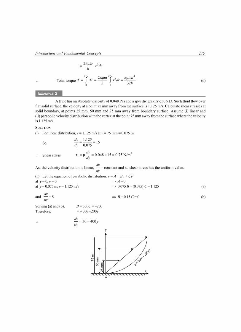
Introduction and Fundamental Concepts 275
32 . r drh
πµω=
∴ Total torque / 2 / 2 4
3
0 0
232
d d dT dT r drh h
πµω πµω= = =∫ ∫ (d)
EXAMPLE 2A fluid has an absolute viscosity of 0.048 Pas and a specific gravity of 0.913. Such fluid flow over
flat solid surface, the velocity at a point 75 mm away from the surface is 1.125 m/s. Calculate shear stresses atsolid boundary, at points 25 mm, 50 mm and 75 mm away from boundary surface. Assume (i) linear and(ii) parabolic velocity distribution with the vertex at the point 75 mm away from the surface where the velocityis 1.125 m/s.
SOLUTION
(i) For linear distribution, v = 1.125 m/s at y = 75 mm = 0.075 m
So, 1.125 150.075
dvdy
= =
∴ Shear stress 20.048 15 0.75 N/mdvdy
τ = µ = × =
As, the velocity distribution is linear, dvdy
= constant and so shear stress has the uniform value.
(ii) Let the equation of parabolic distribution: v = A + By + Cy2
at y = 0, v = 0 ⇒ A = 0at y = 0.075 m, v = 1.125 m/s ⇒ 0.075 B + (0.075)2C = 1.125 (a)
and 0dvdy
= ⇒ B + 0.15 C = 0 (b)
Solving (a) and (b), B = 30, C = –200Therefore, v = 30y –200y2
∴ 30 – 400dv ydy
=
75
mm
50
mm
25
mm v
=30
y–
200y
o
y
y
2

276 Mechanical Science-II
Hence at y = 0, 30,dvdy
= v = 0 ⇒ τ = 1.44 N/m2
y = 0.025, 20,dvdy
= v = 0.625 ⇒ τ = 0.96 N/m2
y = 0.050, 10,dvdy
= v = 0.880 ⇒ τ = 0.48 N/m2
y = 0.050, 0,dvdy
= v = 1.125 ⇒ τ = 0.
EXAMPLE 3A cylinder of 0.12 radius rotates concentrically inside a fixed cylinder of 0.13 m radius. Both the
cylinders are 0.3 m long. Determine the viscosity of the liquid which fills the space between the cylinders if atorque of 0.88 Nm is required to maintain angular velocity of 2π rad/s.
SOLUTION
Torque = Shear stress × Surface area × Lever arm⇒ 0.88 = τ × (2πr × 0.3) × r (a)
⇒ 20.467
rτ =
Now 20.467dv
dr rτ
= =µ µ
⇒ 20.467drdv
r=
µ(b)
Integrating (b), in
out
0.12
20.13
0.467v
v
drdvr
=µ∫ ∫
⇒ Vin – Vout =0.467 1 1–
0.12 0.13 µ
⇒ ω × 0.12 – 0 =0.2993
µ
⇒ 2π × 0.12 =0.2993
µ
⇒ µ = 0.3970 PasHence, absolute value is 0.3970 Pas
0.3 m
0.24 m 0.01 m

Introduction and Fundamental Concepts 277
EXAMPLE 4
The velocity profile is a laminar flow through a round pipe is expressed as 2
20
2 1– ru Ur
=
, where
U = average velocity, r0 = radius of pipe. Draw dimensionless shear stress profile 0
τ τ
against 0
rr
where τ0
is wall shear stress. Find τ0, when oil flows with absolute viscosity 4 × 10⁻² Ns/m2 and velocity of 4 m/s in a pipeof diameter 150 mm.SOLUTION
Given: 2
20
2 1– ru Ur
=
∴ 20
4–du Urdr r
= (a)
∴ 20
4–du Urdr r
µτ = µ = (b)
and 00 0
4–r
du Udr r=
µτ = µ = (c)
So, 0
ττ
= 0
rr
and the plot is shown.
From (c), –2
20
4 4 10 4– 8.534 N/m0.075
× × ×τ = = (in absolute value)
EXAMPLE 5Neglecting temperature effect, the empirical pressure-density relation for water is
7
3001 – 3000.a a
pp
ρ= × ρ Determine isothermal bulk modulus of elasticity and compressibility of water
at 1,10 and 100 atmospheric pressure.SOLUTION
The relation given, 7
3001 – 3000.a a
pp
ρ= × ρ (a)
Differentiating with respect to ρ,
6
71 . 7 3001a a
dpp d
ρ= × ×ρ ρ
⇒ 6
77 3001 aa
dp pd
ρ= × × ×ρ ρ
(r/r0)
(/
)0
1.0
0.5
0
0 0.5 0.1
45°

278 Mechanical Science-II
⇒ 7
7 3001 aa
dp pd
ρρ = × × × ρ ρ (b)
From equation (1.7), dpEd
= ρρ
7
7 3001 aa
p ρ
= × × × ρ
17 3001 3000
3001aa
ppp
= × × × + ×
[Substituting from(a)]
7 3000aa
ppp
= × × + (c)
From equation (c)So, at p = 1pa, E1 = 21007 pa
p = 10pa, E10 = 21070 pa
p = 100pa, E100 = 21700 pa
If pa = 1.0132 × 10⁵ N/m2,E1 = 2.1284 × 10⁹ N/m2, K1= 0.4698 × 10⁻⁹ m2/NE10 = 2.1348 × 10⁹ N/m2, K10= 0.4684 × 10⁻⁹ m2/NE100 = 2.1986 × 10⁹ N/m2, K100= 0.4548 × 10⁻⁹ m2/N
EXAMPLE 6A cylinder 0.35 m3 of air at 50°C and 276 kN/m2 absolute. The air is compressed to 0.071 m3.
(i) Assuming isothermal condition, what is the pressure at new volume and bulk modulus of elasticity at newstate? (ii) Assuming isentropic condition, what is the pressure and bulk modulus of elasticity for γ = 1.4.
SOLUTION
(i) For isothermal condition p1∀1 = p2∀2
⇒ 0.35 × (276 × 103) = 0.071 × p2
⇒ p2 = 1360 × 103 N/m2 = 1.36 MPa∴ Isothermal bulk modulus = p2 =1.36 MPa(ii) For isentropic condition,
p1∀11.4 = p2∀2
1.4
⇒ (0.35)1.4 × (276 × 103) = (0.071)1.4 × p2
⇒ p2 = 2.575 MPa∴ Isentropic bulk modulus = γp2 = 1.4 × 2.575 = 3.605 MPa

Introduction and Fundamental Concepts 279
EXAMPLE 7
The mean free path of a gas is ( )–1/ 21.26 RTµλ =
ρ. Find out air density when mean free path is
10 mm, temperature 20°C, µ = 1.8 × 10⁻⁵ kg/ms, R = 287 J/kg K.
SOLUTION
Here, λ = 10 mm = 0.01 m, µ = 1.8 × 10⁻⁵ kg/msT = 20°C = 293 K, R = 287 J/kg K
From the given relation: ( )–1/ 21.26 RTµλ =ρ
⇒ ( )–1/ 21.26 RTµρ =
λ
( )–5
–1/ 21.8 101.26 287 2930.01×
= × ×
= 7.82 × 10⁻⁶ kg/m3.
EXAMPLE 8A shaft 80 mm in diameter is being pushed through a bearing sleeve of 80.2mm diameter and 0.3 m
long. Assumed uniform clearance is flooded with lubricating oil of viscosity 0.1 kg/ms and specific gravity 0.9.(i) If the shaft moves axially at 0.8 m/s, calculate resistance force exerted by oil on the shaft. (ii) If shaft is axiallyfixed and rotated at 1800 r.p.m., estimate resisting torque exerted by oil and power required.
SOLUTION
(i) Given,
0.2 mm
0.1 kg/ms, = 0.3 m, 0.0001 m,2
l yµ = = =
v = 0.8 m/s, d = 80 mm = 0.08 m∴ Resisting force = τ × πdl
v dly
= µ × × π
0.80.1 0.08 0.3 N0.0001
= × × π × ×
60.32 N=(ii) Given,
µ = 0.1 kg/ms, l = 0.3 m, y = 0.0001 m, d = 0.08 m, N = 1800 rpm
7.539 m/s60dNv π
= =
Shaft
0.3 m
80 mm
0.1 mm

280 Mechanical Science-II
Lubricant film ofthickness 'h'
1m/s
30°
Block contactarea 'A'
w = 1000 N
∴ Resisting force v dly
= µ × × π
7.5390.1 0.08 0.3 N0.0001
= × × π × ×
568.4272 N=
∴ Resisting torque ( )568.4272 × 0.04 Nm=
22.737 Nm=
∴ Power transmitted2 1800 122.737 kW
60 1000π × = × ×
4.285 kW=
EXAMPLE 9A body weighing 1000 N slides down at
a uniform speed of 1 m/s along a lubricated inclinedplane making 30° with the horizontal. The viscosity oflubricant is 0.1 kg/ms and contact area of the body is0.25 m2. Determine the lubricant thickness assuminglinear velocity distribution.
SOLUTION
Let the thickness of oil = h m
∴∴∴∴∴ Velocity gradient 1 per secdu
dy h
=
∴∴∴∴∴ Shearing viscous force acting (F)
. .du Ady
= µ
21 0.025 0.0250.1 0.25 kgm/s N
h h h= × × = =
Horizontal component of the body = 1000 sin 30° = 500 N
∴∴∴∴∴ From condition of equlibrium, 0.025500 mm
h=
⇒ h = 5 × 10⁻⁵ m = 0.05 mm
EXAMPLE 10A uniform film of oil 0.13 mm thick separates two discs, each of 200 mm diameter, mounted
co-axially. Ignoring the edge effects, calculate the torque necessary to rotate one disc relative to other at aspeed of 7 r.p.m., if the oil has a viscosity of 0.14 Pas.

Introduction and Fundamental Concepts 281
r dr
200 mm0.13 mm
SOLUTION
Let us consider an annular element of width ‘dr’, at a distance r from centreline.
Here, –32 2 7
0.14 47365.550.13 10
du rN r rdy dy
π π ×µ = µ = × =
×
∴ Force acting on this element ( ) 47365.55 2dF rdr= × π
∴ Torque acting on this element ( ) 3297606.53dT dF r r dr= × =
∴ Total torque (T) 0.1
3
0
297606.53 7.44 Nm.dT r dr= = =∫ ∫
EXAMPLE 11A piston 79.6 mm diameter and 210 mm long works in a cylinder of
80 mm diameter. If the annular space is filled with a lubricating oil of viscosity0.065 kg/ms, calculate the speed at which the piston will move through thecylinder, when an axial load of 85.6 N is applied. Neglect inertia of the piston.
SOLUTION
Effective area subjected to shear (A) = (π × 0.0796 × 0.21) m2
Let the speed of rotation = v m/s∴ Viscous force acting on the piston (F)
( )
–30.065 0.0796 0.21 N
80 – 79.6 102
v= × × π × × ×
( )17.0673 v N= ×
As per given condition: 17.0673 85.6v× =
⇒ 5.01 m/s.v =
210 mm
79.6 mm
80 mm
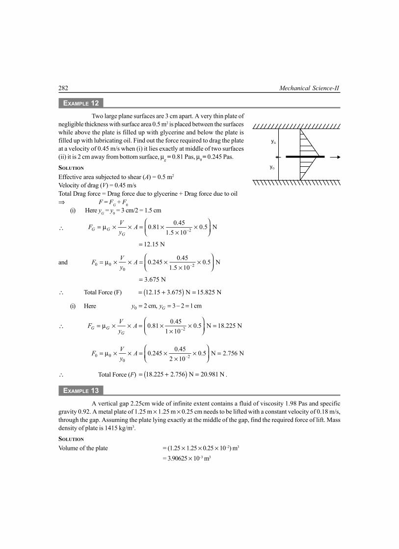
282 Mechanical Science-II
EXAMPLE 12Two large plane surfaces are 3 cm apart. A very thin plate of
negligible thickness with surface area 0.5 m2 is placed between the surfaceswhile above the plate is filled up with glycerine and below the plate isfilled up with lubricating oil. Find out the force required to drag the plateat a velocity of 0.45 m/s when (i) it lies exactly at middle of two surfaces(ii) it is 2 cm away from bottom surface, µg = 0.81 Pas, µ0 = 0.245 Pas.
SOLUTION
Effective area subjected to shear (A) = 0.5 m2
Velocity of drag (V) = 0.45 m/sTotal Drag force = Drag force due to glycerine + Drag force due to oil⇒ F = FG + F0
(i) Here yG = y0 = 3 cm/2 = 1.5 cm
∴ –20.450.81 0.5 N
1.5 10G GG
VF Ay
= µ × × = × × ×
12.15 N=
and 0 0 –20
0.450.245 0.5 N1.5 10
VF Ay
= µ × × = × × ×
3.675 N=
∴ Total Force (F) ( )12.15 3.675 N 15.825 N= + =
(i) Here 0 2 cm, 3 2 1cmGy y= = − =
∴ –20.450.81 0.5 N 18.225 N
1 10G GG
VF Ay
= µ × × = × × = ×
0 0 –20
0.450.245 0.5 N 2.756 N2 10
VF Ay
= µ × × = × × = ×
∴ Total Force (F) ( )18.225 2.756 N 20.981 N= + = .
EXAMPLE 13A vertical gap 2.25cm wide of infinite extent contains a fluid of viscosity 1.98 Pas and specific
gravity 0.92. A metal plate of 1.25 m × 1.25 m × 0.25 cm needs to be lifted with a constant velocity of 0.18 m/s,through the gap. Assuming the plate lying exactly at the middle of the gap, find the required force of lift. Massdensity of plate is 1415 kg/m3.
SOLUTION
Volume of the plate = (1.25 × 1.25 × 0.25 × 10–2) m3
= 3.90625 × 10⁻³ m3
yG
yO

Introduction and Fundamental Concepts 283
∴ Self weight of plate = (3.90625 × 10–3 × 1415 × 9.807) N= 54.207 N
Specific weight of fluid = (0.92 × 1000 × 9.807) N/m3
= 9022.44 N/m3
∴ Buoyant force acting upward = (9022.44 × 3.90625 × 10–3) N= 35.244 N
Therefore effective downward force (F1) = (54.207 – 35.244) N = 18.963 NWhen the plate is within fluid, wall-to-plate clearance on each side
2.25 – 0.25
cm2
=
–21 10 m= ×
Area of plate subjected to shear = (1.25 × 1.25 ) m2 = 1.5625 m2
∴ Shear force acting on each side of plate
–20.181.98 1.5625 N 55.687 N
1 10
= × × = ×
∴ Total shear force on both side of plate (F2)
( )2 55.687 N 111.374 N= × =
To lift up the plate, the total shear force (F2) and effective downward force (F1) of the plate will have toovercome.So the net drag force F = F1 + F2
= (18.963 + 111.374) N = 130.337 N.
EXAMPLE 14The surface tension of water in contact with air at 20°C is 0.0705 N/m. The pressure inside a water
droplet is 0.018 N/cm2 higher than outside pressure. What is the diameter of the water droplet?
SOLUTION
From equation (1.10), ∆p = 0.018 N/cm2 = 180 N/m2
σ = 0.0705 N/m and R1 = R2 = R
∴ 2p
R
∆σ =
⇒ –42 2 0.0705 7.834 10 m180
Rpσ ×
= = = ×∆
1.0 cm
1.0 cm
0.25 cm
F

284 Mechanical Science-II
So, diameter of the droplet = (2 × 7.834 × 10–4) m = 1.5668 × 10⁻³m = 1.57 mm.
EXAMPLE 15
Find surface tension of a soap bubble of 48 mm diameter while pressure inside is 3.12 Pa higherthan atmospheric one.
SOLUTION
As it is a hollow bubble it will have two sets of interface surface, one is inner surface and inside air, other isouter surface and outside air. And surface tension will act both outside surface and inside surface of bubble.Hence
4R
pσ
=∆
⇒ –3. 3.12 48 10 N/m 0.01872 Nm.
4 4 2p R∆ × ×
σ = = =×
EXAMPLE 16Calculate capillary rise in a glass table of 2.35 mm diameter, when vertically immersed in (i) mercury
(ii) water. Surface tension in contact with air is 0.518 N/m for mercury and 0.07238 N/m for water. Specific gravityand angle of contact for mercury is 13.596 and 130° respectively.
SOLUTION
Here, 31000 kg/m ,wρ = 0.07238 N/mwσ =
( ) 313.596 1000 kg/m ,mρ = × 0.518 N/mmσ =
0 , 130w mθ = ° θ = °∴ Capillary rise for water
–34 cos 4 0.07238 cos 0
m1000 9.807 2.35 10
w ww
wh
g dσ θ × × °
= =ρ × × × × ×
0.01256 m 12.56 mm= =Capillary depression for mercury
( ) –34 cos 4 0.518 cos130 m
13.596 1000 9.807 2.35 10m m
mm
hg d
σ θ × × °= =ρ × × × × × ×
–3– 4.2505 10 m – 4.25 mm= × =Here, (–) ve sign indicates capillary fall instead of capillary rise.
EXAMPLE 17The space between a shaft and a concentric sleeve is filled up with Newtonian fluid. If a force of
550 N is applied parallel to the shaft, the sleeve attains a speed of 1.3 m/s. How much speed will attain the sleeve,if above force is increased to 1550 N, the temperature being the same?

Introduction and Fundamental Concepts 285
SOLUTION
Let the clearance between shaft and sleeve be ‘dy’, radius of the shaft‘r’ and length of sleeve ‘l’.Viscosity remaining same, we obtain two sets of equations
( )1.3550 2 rldy
= µ × × π (a)
( )1550 2V rldy
= µ × × π (b)
Doing (b) ÷ (a), 1550550 1.3
V=
⇒ 3.66 m/s.V =
EXAMPLE 18A hydraulic ram 200 mm diameter and 1.2 m long moves within a concentric cylinder 200.2 mm
diameter. The annular clearance is filled with oil of relative density 0.85 and kinematic viscosity 400 mm2/s. Whatis the viscous force resisting the motion when the ram moves at a speed of 120 mm/s.
SOLUTION
Dynamic viscosity (µ) = υρ= (400 × 10–6 × 0.85 × 103) Ns/m2
= 0.34 Ns/m2
So, Shear stress τ dudy
= µ ×
1200.34200.2 – 200
2
= ×
= 408 N/m2
∴ Shear force (F) = τ × (πdl)= 408 × (π × 200 × 10–3 × 1.2) N= 307.62 N.
EXAMPLE 19The space between two large flat and parallel walls 25 mm apart is filled with liquid of viscosity
0.7 Ns/m2. Within this space a thin flat plate 250 × 250 is towed at a velocity of 150 mm/s at a distance of 19 mmfrom one wall, the plate and its movement being parallel to the walls. Assuming linear variations of velocitybetween the plate and the walls, determine the force exerted by the liquid on the plate.
Shaft
dy
L

286 Mechanical Science-II
SOLUTION
Effective area of plate on shear (A)= 250 × 250 × 10–6 m2
= 0.0625 m2
Velocity of drag (V) = 150 mm/s = 0.15 m/s
Total drag force (F) = 1 2
V V At t
µ × + µ ×
= –31 1 10.7 0.15 0.0625 N6 19 10
× + × × = 1.439 N.
EXAMPLE 20A large plate moves with speed v0 over a stationary plate on a layer of oil. If the velocity profile is
that of a parabola, with the oil at the plates having the same velocity as the plates, what is the shear stress onthe moving plate from the oil? If a linear profile is assumed, what is the shear stress on the upper plate?SOLUTION
Let us assume equation of parabolic velocity profile v2 = k1y (a)
Applying boundary condition at y = d, v = v0
From (a), 20 1v k d=
⇒ 20
1v
kd
=
∴ 2
2 0 .vv y
d=
⇒ 0yv vd
=
So, –1/ 20 1. .2
vdv ydy d
=
( ) 01/ 2vdy
=
At 0 01. ., |2 2y d
v vdvy ddy dd d=
µµ= τ = µ = =
Considering linear profile, v = k2 y
at y = d, v = v0 ⇒ 02
vkd
=
∴ 0 .vv yd
=
Oil Layer
y
v0
v
LinearProfile
dParabolic Profile
19 mm
6 mm
25 mm

Introduction and Fundamental Concepts 287
⇒ 0vdvdy d
=
∴ 0vdvdy d
τ = µ = µ
At 0, vy dd
= τ = µ .
EXERCISE
1. (a) State and explain Newton’s law of viscosity.
(b) Define Newtonian and Non-Newtonian fluids with examples.
2. Define the following terms(a) Surface Tension (b) Rheology(c) Ideal fluid (d) Bulk modulus of elasticity of a compressible fluid
3. Explain dynamic viscosity and kinematic viscosity. Give their dimensions.
4. Explain the phenomenon of capillarity. Obtain an expression for capillary rise of a fluid.
5. A plunger is moving through a cylinder at a speed of 6.1 m/s. The diameter and length of the plungerare 126.7 mm and 25 mm respectively. The diameter of the cylinder is 127 mm. The film of oil separatingplunger from the cylinder has a viscosity of 0.95765 N-s/m2. What is the force required to maintain thismotion?
Ans. [12.275 N]
6. Calculate the density, specific weight and volume of chloride gas at 25°C and pressure of6,00,000 N/m2 absolute.
Ans. [ 17.1 kg/m3, 168 N/m3, 0.0585 m3/kg]
7. A high pressure steel container is partially full of a liquid at a pressure of 10 atm. The volume of theliquid is 1.232 L. At a pressure of 25 atm, the volume of the liquid equals 1.231 L. What is the averagebulk modulus of elasticity of the liquid over the given range of pressure of the temperature aftercompression is allowed to return to the original temperature. What is the coefficient of compressibility?
Ans. [1.872 × 10⁶ k Pa, 0.000534 m2/MN]
8. Water is moving through a pipe. The velocity profile is given by 2
2–4 4
dv r β= µ
What is the shear
stress at the wall of the pipe and at r = d/4. If the given profile persists a distance L along the pipe, whatdrag is induced by the water on the pipe in the direction of flow over this distance?
Ans. 22β β βπ– , – ,
4 8 4r d d L

288 Mechanical Science-II
9. A cylinder of weight 9.1 kg, diameter 152 mm and height 127 mm slides through a lubricated pipe. Theclearance between cylinder and pipe is 0.025 mm. If the cylinder is observed to decelerate @ 0.61 m/s2
when the speed is 6.1 m/s, what is the viscosity of the oil?Ans. [ 6.411 × 10⁻³ Pas]
10. In a stream of glycerine in motion, at a certain point, the velocity gradient is 0.25 m/s/m. Mass densityof fluid is 1268.4 kg/m3 and kinematic viscosity is 6.30 × 10⁻⁴ m2/s. Calculate shear stress at that point.
Ans. [ 0.2 N/m2]11. Surface tension of water in contact with air at 20°C is given as 0.0716 N/m. Pressure inside a droplet of
water is to be 0.0147 N/cm2 greater than the outside pressure, calculate diameter of droplet of water.
Ans. [1.94 mm]
12. Find surface tension in a soap bubble of 30 mm diameter when the inside pressure is 1.962 N/m2 aboveatmosphere.
Ans. [0.00735 N/mm]
13. Capillary rise in the glass tube used for measuring water level is not to exceed 0.5 mm. Determine itsminimum size, given that surface tension for water in contract with air = 0.07112 N/m.
Ans. [5.8 cm]
14. A very large thin plate is centered in a gap of width 6 cm with different oil of unknown viscositiesabove and below, the viscosity of one being twice that of the other. When pulled at a velocity of30 cm/s, the resulting force on 1 m2 of plate due to viscous shear on both sides is 29.4 N. Assumingviscous flow and neglecting all end effects, calculate viscosities of the oil.
Ans. [0.98 Pas, 1.96 Pas]

2.1 FORCES ON FLUID ELEMENTIf an infinitesimally small region in the continuum of fluid can be separated out, then that particularregion is defined as a fluid element. A fluid element, on isolation from all its surroundings issubjected to variety of forces, whether it is in rest or in motion. All the forces acting on any fluidelement can be classified broadly into two groups:
(a) Body Forces: are forces acting throughout the body of the fluid element and distributedover entire volume of the element. Forces due to gravitational acceleration, electromagneticfield are such body forces. These are expressed as force per unit mass.
(b) Surface Forces: are forces acting directly on the surface of fluid element in contact. Viscousforce is such a surface force. All surface forces are normally resolved along normal directionand perpendicular to the normal (tangential) direction. Hence surface forces have twocomponents, one is normal force and the other is tangential force.
2.1.1 Pascal’s Law of HydrostaticsLet us consider a small tetrahedral fluid element OABC asshown in Figure 2.1. Triangular face ABC has aninfinitesimally small area dA , which makes angle α withx-plane(bounded by y-axis and z-axis),angle β withy-plane(bounded by x-axis and z-axis) and angle γ withz-plane(bounded by x-axis and y-axis). Now projection of‘dA’ on x-plane, y-plane and z-plane are
1. .cos21. .cos21. .cos2
dA dy dz
dA dx dz
dA dx dy
α = β = γ =
2CHAPTER
FLUID STATICS
z
B
dz
A
y
C
x
dx dyO
Differential Tetrahedron
z
x Y
Fig. 2.1
(2.1)

290 Mechanical Science-II
Now, σ is pressure of fluid in any arbitrary direction and σx , σy , σz indicate pressure alongx-axis, y-axis and z-axis respectively.
To attain conditions of equilibrium of the tetrahedral element, the normal surface forces due tofluid pressure along the co-ordinate axes will have to be resolved. Therefore
. .– cos 02
. .– cos 02
. .– cos 02
x
y
z
dy dz dA
dx dz dA
dx dy dA
σ σ α = σ σ β = σ σ γ =
(2.2)
Clubbing (2.1) & (2.2), we obtain,
00
0
x
y
z
σ =σ = σ =
(2.3)
or σ = σx = σy = σz (2.4)As the direction of σ acting normal to the surface dA is arbitrary, pressure at a point in a
static fluid is the same in all direction. This is known as Pascal’s Law of hydrostatics, asestablished by a French Mathematician, B.Pascal in 1653. Very commonly the stress σ in equation(2.4) is denoted as p, a scalar quantity.
2.2 EQUILIBRIUM OF STATIC FLUIDELEMENT
Let us consider a differential fluid element in the shape ofa parallelepiped, shown in figure 2.2. It is subjected to bothbody force and surface force. Body force arises due toearth’s field of gravitation and surface force due to normalpressure acting on element.
The component of body force along co-ordinate axesare X, Y and Z, per unit mass. Mass density of the elementis ρ. Normal pressure p is acting on rear surface of theelement in x-plane, as shown.
Rate of change of p along dx length = px
∂∂
So, the normal pressure on front surface of the element in x-plane pp dxx
∂ = + ∂
Differentialfluid element
x
y
z
o
p
dz
dy
∂pp + dx
∂x
dx
Fig. 2.2

Fluid Statics 291
Considering equilibrium of forces along x-axis
– 0pp dy dz p dx dy dz X dx dy dzx
∂ + + ρ = ∂
⇒ – – 0pp p dx X dxx
∂+ ρ =
∂
⇒ 1 p X
x∂ =
ρ ∂ (2.5)
In the similar fashion, we can consider the equilibrium along y-axis and z-axis, finally yieldingEuler’s Equations of Equilibrium as
1 p X
x∂ =
ρ ∂ (2.6a)
1 p Y
y∂ =
ρ ∂ (2.6b)
1 p Z
z∂ =
ρ ∂ (2.6c)
2.3 SOLUTION OF EULER’S EQUATIONSLet us consider a specific case, where the fluid is static and z-axis coincides with the direction ofgravitational acceleration. Here component of body forces along x-axis and y-axis are zero, i.e.,X = 0 = Y.
Due to special choice of coordinate axes, the partial differential form in equation (2.6c) can bechanged to total differential form. Replacing Z by –g [(–)ve sign due to downward direction of g],above equation can be re-written as
1 –dp gdz
=ρ
(2.7)
Solution of this equation may be found for the following cases.
2.3.1 Incompressible Fluid (uniform density)Adjoining figure 2.3 illustrates this specific condition. Tofind expression of pressure p at any z height, we are tointegrate equation (2.7).
1 –dp g dz=ρ∫ ∫
⇒ 0–p gz C= +ρ
H
h
z
z
pa
Atmospheric Pressure
Fig. 2.3

292 Mechanical Science-II
⇒ p = –ρgz + C , where C = ρ .C0 (2.8)Applying boundary condition as, at z = H, p = pa
pa = –ρgH + C⇒ C = pa + ρgH (2.9)
Substituting in equation (2.8), p = –ρgz + pa + ρgH⇒ p = pa + ρg (H – z) = pa + ρgh (2.10)
Here this expression is formed in terms of absolute pressure. In terms of gauge pressure,pa = 0 and it will be, p = ρgh (2.11)
2.3.2 Isothermal StateAt initial reference level, say, on earth’s surface, the pressure and mass density of compressiblefluid are p0 and ρ0 respectively. Applying Boyle’s Law,
0
0
pp=
ρ ρ (2.12)
Substituting in equation(2.7), 1 –dp gdz=ρ
⇒ 0
0
. –pdp gdz
p=
ρ [ ]substituting from eq. 2.12 (2.13)
Integrating 0 0
0
0–
p z
p z
p dp g dzp
=ρ ∫ ∫
⇒ ( )00
0 01n – –
p p g z zp
= ρ (2.14)
⇒ ( )00
0 01n – –
gp z zp p
ρ=
⇒ ( )00
0 0exp – –
gp z zp p
ρ=
(2.15)
For a perfect gas,
0
00
p R T=ρ (2.16)
Substituting in equation (2.15),
( )00 0
exp – –p g z zp RT
=

Fluid Statics 293
⇒ ( )0
00
– –. expg z z
p pRT
=
(2.17)
2.3.3 Adiabatic StateFor an adiabatic process,
0
0
ppκ κ=
ρ ρ (2.18)
⇒ 1/
00
kpp
ρ = ρ
(2.19)
Substituting in equation (2.7),
1/
0
0
1 . –kp dp gdz
p
= ρ (2.20)
Integrating 0 0
1/ –1/0
0
1 . . –p Z
k k
p z
p p dp g dz=ρ ∫ ∫ (2.21)
⇒ ( )0
1–1/1/
0 0 0. – –1 –1/
pkk
p
pp g z zk
= ρ
⇒ ( )1/ 1–1/1–1/0 0 0 0
. . – – ––1
k kkkp p p g z zk
= ρ (2.22)
⇒ ( ) 1/ –1 1–1/ 1–1/0 0 0 0 0. .– . –
–1k k kkg z z p p p p
k ρ = (2.23)
So, from equation (2.23),
( )–1
00
0 0– 1 –
–1
kkpk pz z
k g p
= ρ
⇒ ( ) –100
0 0
–11 – –
kkgp kz z
p p k ρ =
( ) –10
0
–11 – –
kkg kz z
RT k =
(2.24)

294 Mechanical Science-II
2.3.4 Polytropic StateIn a polytropic process,
0
0n n
pp =ρ ρ (2.25)
Following equation (2.24) and (2.25), we can write,
( ) –10
0 0
–11 – –
nnp g nz z
p RT n =
(2.26)
2.3.5 Temperature Lapse RateThe variation of temperature in atmosphere with altitudefrom M.S.L. is shown in figure 2.4. Troposphere is incontact with the surface of the earth up to an altitude of 7km in polar and 14 km in equatorial region, averaging 11km in general. And lapse rate (α) of temperature isconstant, 6.5 K/km, and T0 = 288 K, while
T = T0 – αz (2.27)As we know, p = ρRT and from equation (2.7)
( )0–
–dp g dzp R T z
=α (2.28)
Integrating within limits,
0
0 0 0
–ln ln
–T zp g
p R T z α
= α α
⇒ 0
0 0 0
–exp. ln
–T zp g
p R T z α
= α α (2.29)
2.4 GAUGE PRESSURE AND ABSOLUTE PRESSUREThe air in the atmosphere exerts a natural pressure on all the surfaces in contact, which is knownas Atmospheric Pressure. It varies with change of altitude and can be measured with the help ofa barometer. Hence atmospheric pressure is sometimes denoted as Barometric Pressure. In normalcondition this pressure at mean sea level is
76 cm of mercury column=10.33 m of water column=10,330 kgf/m2 = 101.32 kN/m2 = 1.013 bar
The pressure exerted by any fluid can be measured either (i) absolute zero as datum, or(ii) atmospheric pressure as datum. When pressure is measured considering vacuum or absolute
100
80
60
40
20
0–100 –80 –60 –40 –20 0 20
Ionosphere
Mesosphere
Temperature °C
Altitude
km
StratosphereTroposphere
Fig. 2.4

Fluid Statics 295
zero as datum, it is called an Absolute Pressure. If the datum be atmospheric pressure, themeasured pressure is termed as Gauge Pressure. So,
Gauge pressure = Absolute pressure – Atmospheric pressure.If gauge pressure is below atmospheric pressure, then it is called Negative gauge pressure or
Vacuum pressure or Suction pressure.
2.4.1 BarometerThe instrument which measures atmospheric pressure is known asbarometer and is shown in figure 2.5. The column of mercury rises inthe inverted tube by capillarity and the space above this columnapparently empty but actually is filled up with mercury vapour, isknown as Torricellian Vacuum. Hence the atmospheric pressure canbe expressed as,
patm = pvap + ρgh (2.30)Generally, the effect of vapour pressure is neglected in computation
of atmospheric pressure but an error of 0.14% to 0.16% is invoked.
2.5 MEASUREMENT OF PRESSUREThere happens to exist number of devices, applying which the fluid pressure can be measured.
VapourPressure
pa
h
Fig. 2.5
Pressure MeasuringDevices
Manometer Mechanical Gauge
SimpleManometer
DifferentialManometer
BourdonTube
PressureGauge
DiaphragmPressure
Gauge
Piezometer U-tubeManometer
Inclined TubeManometer
BellowsPressureGauge
Dead WeightPressureGauge
U-tubeDifferentialManometer
Inverted U-tubeDifferentialManometer
MicroManometer

296 Mechanical Science-II
2.6 MANOMETERA manometer is a device for measuring the difference between two pressures by balancing acolumn of liquid.
2.6.1 Simple ManometerIt measures pressure at point in a fluid contained in a conduit or vessel.
(a) Piezometer: It is an ordinary vertical tube, connected to a conduitcarrying liquid is used to measure gauge pressure, and is called apiezometer tube or simply a piezometer, as ‘piezo’ means ‘pressure’.
The liquid in piezometer rises freely until equilibrium. In figure 2.6, ‘h’ isthe pressure head at A. Piezometer cannot measure pressure too high due tolarge length of tube and vacuum pressure due to air entrance inside conduit.
(b) U-tube manometer: A U-tube, as shown in figure 2.7, may be usedto measure pressure in a conduit or container having a fluid of massdensity ρA. The manometric tube should contain a liquid having massdensity ρB, such that ρB > ρA. For water and alcohol, commonmanometric fluid is mercury, while for gas it may be water.Now in order to write an equation for pressure equilibrium, following mnemonic, first suggestedby Professor John Foss of Michigan State University, can be used.
p ↓ = p↑ + γ ∆ z (2.31)Following this, pressure at P
pp = p1 + ρA .g (y + x) (2.32)
Then jump across along the same line at Q. Aslevel is not changing, then
pQ = pp= p1 + ρA . g (y + x) (2.33)
Now, pressure at open end of the tube patm = pQ – ρB . g . x = p1 + ρA .g (y + x) – ρB . g . x (2.34a)
⇒ p1 = patm + (ρB – ρA ) g.x – ρA .g.y (2.34b)(c) Inclined tube manometer: It is just a
modification of an ordinary U-tube manometer,for improvement of sensitivity, shown in figure 2.8.The c/s area of the reservoir is made much higherthan that of the inclined tube. This arrangement enables the manometric liquid remainpractically constant in the reservoir due to a small change in pressure. The inclined tubefacilitates the movement ‘l’ of the meniscus to be recorded with greater sensitivity, andsatisfies the relation
h = l sinθ (2.35)
h
+A
Fig. 2.6
A
P
B
Q
y
x
patm
p1
Fluid
Fluid
Fig. 2.7

Fluid Statics 297
Here smaller the inclination, higher is the sensitivity. Butan inclination less than 5° makes the reading of the exactposition of meniscus troublesome and hence should not beused.
2.6.2 Differential ManometerIt is used to determine a small or moderately high pressuredifference between any two points in two conduits or two
reservoirs. A light oileven air may be themanometric fluid.Normally U-tube differential manometer is employed toascertain high pressure difference (Fig. 2.9). InvertedU-tube manometer, shown in figure 2.10, generallymeasures low or moderate pressure difference.Theprocedure for obtaining equilibrium equation for pressuredifference is same as before. Referring figure 2.9.
pA + ρ1gz1 – ρ2gz2 – ρ3gz3 = pB
⇒ pA – pB
= ρ2gz2 + ρ3gz3 – ρ1gz1 (2.36)
Again for inverted U-tube manometer in figure 2.10,
pA – ρ1gz1 + ρ2gz2 + ρ3gz3 = pB
⇒ pA – pB = ρ1gz1 – ρ2gz2 – ρ3gz3 (2.37)
2.6.2.1 MicromanometerSometimes it is necessary to measure small pressure differenceaccurately and micromanometer is employed. As shown in figure 2.11,it is seen that other than manometric fluid and working fluid, anothergauge fluid is used. The equation of hydrostatic equilibrium will be
p1 + ρw . g (h + ∆z) + ρG
. g (z + 2y
– ∆z)
– ρm . g . y – ρG
. g (z – 2y
+ ∆z) – ρw . g (h – ∆z ) = p2 (2.38)
Here ρm > ρG > ρwFrom continuity of gauge liquid
A . ∆z = a . y/2 (2.39)
A
B
h
l
Fig. 2.8
!3 Z3
Z2!2!1
Z1
+ B
+ A
Fig. 2.9
Z2
!2
Z3
!3
!"Z1
+ A
+ B
Fig. 2.10

298 Mechanical Science-II
Initial Level ofGauge Liquid
h
Working Fluid ofDensity
!wp1
p >p1 2
c/s area 'A'
c/s area 'a'
Gauge Liquid
of Density !G
P!m G w> >! !
Manometric iquid
of ensity
L
D #m
Q
Initial Level ofManometric
Fluid2
y
2
y
z
$z$z
p2
Fig. 2.11
Clubbing (2.38) and (2.39), we find
1. . . .. .– –
2 2 2w G ma y y a yp g h g z g yA A
+ ρ + + ρ + ρ
2. . . .– – – –
2 2 2G wy a y a yg z g h p
A A ρ + ρ =
⇒ 1 2. . . . . . . . .– –w G G m
a ap g y g y g y g y pA A
+ ρ + ρ ρ ρ =
⇒ 1 2– – 1 – –m G wa ap p gyA A
= ρ ρ ρ (2.40)
If , 0aA aA
>> ≈
Therefore, p1 – p2 ≈ gy (ρm – ρG ) (2.41)
2.7 HYDROSTATIC FORCE ON SUBMERGEDPLANE SURFACE
Let us consider a plane surface of arbitrary shape and ofarea A, completely submerged below the free surface ofliquid MN. The plane makes an angle θ with the horizontal.The reference system of axes is shown in figure 2.12. Theforce acting on the elemental area dA at a vertical depth hcan be written
dF = ρgh dA (2.42)On integration over the entire area A, total force acts
as
M N
hh
y
x
xcG
C
dA
y
yc
d
A
y
xx
Fig. 2.12
Fluid Statics 299
[ ]sin sinA A A
F dF gh dA gy dA h y= = ρ = ρ θ = θ∫ ∫ ∫ ∵
sinA
g y dA= ρ θ∫ (2.43)
As we know, centroidal coordinate of the plane is ( , )G x y
A
A
y dAy
dA= ∫
∫So,
Ay dA Ay=∫
Substituting in equation (2.43),
( )sinF g A y= ρ θ
= g Ahρ sinh y = θ ∵ (2.44)
This is the resultant hydrostatic force acting on the plane. Let us consider the point C (xC, yC)as centre of pressure, where the above force acts. Considering moment equilibrium about x-axis,we can write,
.C A
y F y dF= ∫
⇒ 1 . ( sin )C A
y y gy dAF
= ρ θ∫
2 2( sin )
( sin )A A
A A
gy dA y dA
gy dA y dA
ρ θ= =
ρ θ∫ ∫∫ ∫ (2.45)
Similarly, from moment equilibrium about y-axis,
1
C Ax xdF
F= ∫
( sin )
sinA A
A A
g xy dA xy dA
gy dA y dA
ρ θ= =
ρ θ∫ ∫∫ ∫
(2.46)
Again, second moment of area about x-axis, applying parallel axis theorem,
2 2x xA
y dA I I Ay= = +∫ (2.47 a)
and product moment of area, applying parallel axis theorem
xy x yAxy dA I I Ax y= = +∫ (2.47 b)
Substituting in equation (2.45) and (2.46),

300 Mechanical Science-II
2
x xC
I Ay Iy yAy Ay+= = + (2.48 a)
x y x yC
I A x y Ix x
A y A y+
= = + (2.48 b)
It is of special mention that, while the plane area becomes symmetrical about any of the
centroidal axes orx x y y= = , then x yI becomes zero and
– xC
Id y yAy
= = (2.49)
2.8 HYDROSTATIC FORCE ONSUBMERGED CURVED SURFACE
A curved surface of total area A in 3-D Cartesiancoordinate system is shown in figure 2.13. Its outersurface is subjected to atmospheric pressure, whilethe inner surface under liquid pressure. Free surfaceof the liquid coincides with x – y plane. An elementalarea dA is considered, while an elemental force dFacts along the outer normal to this area. If l, m, andn be the direction cosines of the outer normal todA, then
dAx = dA.l = dA cosαdAy = dA.m= dA cosβ (2.50)dAz = dA .n = dA cosγ
Here dAx, dAy, dAz are the projections of dA on x-plane, y-plane and z-plane, respectively. So,along x, y and z direction, components of forces are
dFx = ρgzdAx
dFy = ρgzdAy (2.50)dFz = ρgzdAz
On integration total forces on those three planes are
x x x xF gzdA gz A= ρ = ρ∫ (2.51 a)
y y y yF gzdA gz A= ρ = ρ∫ (2.51 b)
z z zF gzdA gzA g= ρ = ρ = ρ ∀∫ (2.51 c)
D
z
dFz
dFx
Fx
EdFyE'D'
C
dAx
Axy c
Q'
zc
P' PA
dA
x
yQ
Fig. 2.13

Fluid Statics 301
Here xz and yz are centroid of the projected area Ax and Ay respectively and ∀ is the volumeof liquid supported vertically by the surface A. To find the coordinate of centre of pressure C ofthe horizontal force Fx ,
. x
Cx
z dFz
F= ∫
and. x
Cx
y dFy
F= ∫
2 .
.x
x x
z dAA z
= ∫
.
.x
x x
yz dAA z
= ∫
.y
x x
IA z
= .yz
x x
IA z
= (2.52)
2.9 BUOYANCY & ARCHIMEDES LAWWhile a body is submerged entirely or partially in a non-reacting, insoluble, static fluid, it experiences an upwardvertical lift. This phenomenon is called ‘buoyancy’ and theupward thrust generated is ‘buoyant force’.
Referring to figure 2.14, the resultant horizontal forcein any direction for such a closed surface is zero. Toevaluate the vertical resolution of resultant hydrostaticforce, an elemental vertical prism of c/s are dAz is assumed,the top surface which is at z1 height and bottom surface atz2 height. Considering the condition of vertical equilibrium,
dFB = dF2 – dF1
= p2 . dAz – p1
. dAz
= ρg (z2 – z1)dAz
= ρgd∀ (2.53)Where d∀ is the volume of the elemental prism. Integrating the equation we obtain,
FB = ∫∀ ρgd∀ = ρg∀ (2.54)Here ∀ is total volume of the body. To obtain the point of action of buoyant force,
xB . FB = ∫x . dFB
⇒ xB = .x gd xd
g
ρ ∀ ∀=
ρ ∀ ∀∫ ∫ (2.55)
And xB is the centroid of the displaced volume of liquid. Explaining this, Archimedes(285–212 B.C.) propounded his famous law, which states,
z
x
xB
O x
z2
z1
p1
dF1
FB
BdAz
Free surface patm
dF2
Fig. 2.14
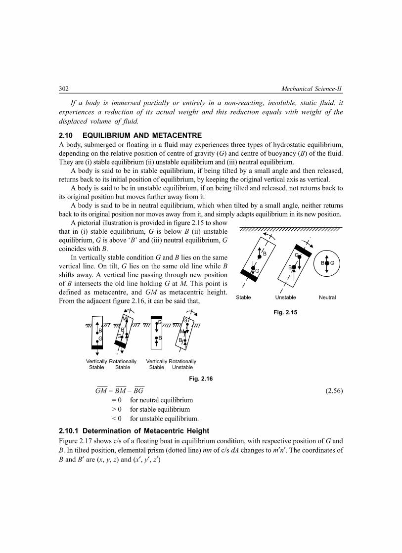
302 Mechanical Science-II
If a body is immersed partially or entirely in a non-reacting, insoluble, static fluid, itexperiences a reduction of its actual weight and this reduction equals with weight of thedisplaced volume of fluid.
2.10 EQUILIBRIUM AND METACENTREA body, submerged or floating in a fluid may experiences three types of hydrostatic equilibrium,depending on the relative position of centre of gravity (G) and centre of buoyancy (B) of the fluid.They are (i) stable equilibrium (ii) unstable equilibrium and (iii) neutral equilibrium.
A body is said to be in stable equilibrium, if being tilted by a small angle and then released,returns back to its initial position of equilibrium, by keeping the original vertical axis as vertical.
A body is said to be in unstable equilibrium, if on being tilted and released, not returns back toits original position but moves further away from it.
A body is said to be in neutral equilibrium, which when tilted by a small angle, neither returnsback to its original position nor moves away from it, and simply adapts equilibrium in its new position.
A pictorial illustration is provided in figure 2.15 to showthat in (i) stable equilibrium, G is below B (ii) unstableequilibrium, G is above ‘B’ and (iii) neutral equilibrium, Gcoincides with B.
In vertically stable condition G and B lies on the samevertical line. On tilt, G lies on the same old line while Bshifts away. A vertical line passing through new positionof B intersects the old line holding G at M. This point isdefined as metacentre, and GM as metacentric height.From the adjacent figure 2.16, it can be said that,
B
G
B
G
MG
B
M
G
B
VerticallyStable
RotationallyStable
VerticallyStable
RotationallyUnstable
Fig. 2.16
GM = BM – BG (2.56)= 0 for neutral equilibrium> 0 for stable equilibrium< 0 for unstable equilibrium.
2.10.1 Determination of Metacentric HeightFigure 2.17 shows c/s of a floating boat in equilibrium condition, with respective position of G andB. In tilted position, elemental prism (dotted line) mn of c/s dA changes to m′n′. The coordinates ofB and B′ are (x, y, z) and (x′, y′, z′)
Fig. 2.15

Fluid Statics 303
Initial volume ∀ = ∫A zdA (2.57 a)New immersed volume ∀/ = ∫A (z + xα)dA (2.57 b)If the rotation α is so provided that both the above
volumes remaining the same, ∫A zdA = ∫A (z + xα)dA
⇒ ∫A x .dA = 0(2.58)
This implies that y-axis must pass through centroidof area A. Now,
∀.x = ∫A x .zdA, ∀.y = ∫A y .zdA, ∀.z = 12
∫A z2dA (2.59)
∀′.x′ = ∫A x(z + xα)dA, ∀′.y′ = ∫A y(z + xα)dA, ∀′.z′ = 12
∫A(z2 – x2α2)dA
So, considering, ∀ = ∀′
BB′ = x′ – x = α∀
∫A x2dA = α∀
. Iy
⇒ BM .α = α∀
. Iy
⇒ BM = yI∀
(2.60)
Hence, GM = BM – BG = yI∀
– BG (2.61)
Multiple Choice Questions
1. Pressure at a point in a static mass of liquid depends upon(a) shape and size of container(b) depth below free liqiuid surface(c) specific weight of liquid and depth below free liquid surface(d) all the above
2. Differential form of pressure variation in static fluid is (z measured vertically upward)(a) dp = –γdz (b) dp = –ρdz(c) dρ = –γdz (d) dp = –zdρ
3. Atmospheric pressure is(a) gauge pr. – Abs. pr. (b) abs. pr. – Gauge pr.(c) abs. pr. – Vacuum pr. (d) gauge pr. + Vacuum pr.
Equilibrium Position Tilted Position
m
m
z z
B W
G
On n'x O
M
nG W
B'WB
,x

304 Mechanical Science-II
4. Pressure in metre of oil (sp. gr. = 0.78), equivalent to 80 m of water is(a) 64.32 (b) 80.64(c) 102.56 (d) 88.18
5. In isothermal atmosphere, the pressure(a) varies in same way as in density(b) linearly decrease with elevation(c) exponentially increase with elevation (d) remains constant
6. To avoid capillary correction in manometer, diameter of tube should be(a) = 5 mm (b) < 3 mm(c) < 5 mm, > 3 mm (d) ≥ 6 mm
7. Centre of pressure for a plane, vertically immersed in static mass of fluid is(a) always above centroid of area(b) always coinciding with centroid of area(c) sometimes above, sometimes below centroid of area(d) always below centroid of area
8. Horizontal force component on a submerged curved surface is(a) weight of liquid vertically above the surface(b) weight of liquid retained in the surface(c) product of area and pr. at centroid(d) force on a vertical projection of curved surface
9. Vertical force component on a submerged curved surface is(a) force on horizontal projection of curved surface(b) product of area and pr. at centroid(c) weight of liquid vertically above curved surface(d) its horizontal component
10. A small boat carrying 5 passengers in a pond. If all passengers jump out of boat to pond, the waterlevel in pond will(a) rise (b) fall (c) not change
11. Buoyant force is(a) resultant force on floating body from fluid surrounding(b) resultant force on any body(c) volume of displaced liquid(d) force necessary to maintain equilibrium of a submerged body
12. Line of action of buoyant force acts through(a) C.G. of any submerged body(b) centroid of volume of any floating body(c) centroid of displaced volume of fluid(d) centroid of horizontal projection of body

Fluid Statics 305
13. A body will float in stable equilibrium, if(a) metacentric height zero(b) C.G. is below centre of buoyancy(c) metacentric height positive and C.G. above centre of buoyancy(d) metacentre above C.G.
14. Normal stress is same in all direction at a point in a fluid(a) when the fluid is at rest(b) when fluid is inviscid(c) when fluid is inviscid and incompressible
15. Hydrostatic force on one side of a circular surface of unit area, with centroid 10 m below free waterlevel (density ρ) is(a) < 10 ρg(b) = 10 ρg(c) ρg × vert.dist. from free surface to centre of pressure(d) none of the above.
16. Differential manometer is used to measure(a) velocity at a point in fluid(b) pressure at a point in fluid(c) difference of pressure between two points in fluid(d) none of the above
17. Water column equivalent to 760 mm of mercury is(a) 1.033 m (b) 10.33 m(c) 0.033 N mm (d) 10.33 N/mm2
18. Hydrostatic law states that rate of increase of pressure in a vertical direction is equal to(a) density of fluid (b) specific gravity of fluid(c) specific weight of fluid (d) none of the above
19. Sensitiveness of an ordinary U-tube manometer can be increased without changing manometer fluidby(a) setting it horizontal (b) keeping it vertical(c) setting it inclined (d) none of the above
20. A manometer may be(a) single limbed (b) double limbed(c) multilimbed (d) all of the above
21. Mercury is used in barometer on account of(a) negligible capillary effect (b) high density(c) very low vapour pressure (d) low compressibility

306 Mechanical Science-II
22. The problems of hydrostatics are influenced by following forces(a) gravity and viscous force (b) gravity and pressure force(c) viscous and surface tension force (d) gravity and surface tension force
23. Indicate the variation of hydrostatic pressure with depth below free surface(a) it decreases with increase in depth(b) there is no change with depth(c) it increases with increase in depth(d) after a certain depth, there is no change in pressure
24. Absolute pressure in flow system(a) always above local atm. pr.(b) is a vacuum pressure(c) may be above, below or equal to the local atm. pr.(d) is also called negative pr.
25. Local atmospheric pressure is measured by(a) barometer (b) bourdon gauge(c) vacuum gauge (d) manometer
26. Gauge pressure in flow system are measured by(a) manometer (b) aneroid barometer(c) vacuum gauge (d) bourdon gauge
27. Absolute pressure is measured by(a) Bourdon gauge (b) aneroid barometer(c) differential manometer (d) hook gauge
28. Point through which resultant hydrostatic force acts is called(a) metacentre (b) centre of pressure(c) centre of buoyancy (d) centre of gravity
29. Mercury is used in manometer for measuring(a) low pressure accurately (b) large pressure only(c) all pressure except smaller ones (d) very low pressure
30. A floating body displaces a volume of liquid equal to(a) its own volume (b) its own weight(c) its submerged weight (d) none of the above
31. Centre of buoyancy is(a) the point through submerged weight of body acts(b) the point through which buoyancy force acts(c) the point through which resultant hydrostatic force acts(d) centre of gravity of liquid displaced by the body
Fluid Statics 307
32. Metacentric height is the distance between(a) C.G. and metacentre (b) C.G. and centre of buoyancy(c) metacentre and centre of buoyancy (d) none of the above
33. Metacentric height of a floating body depends on(a) the shape of its water-line area (b) volume of liquid displaced by the body(c) distance between metacentre and C.G. (d) none of the above
34. A floating body will remain in stable equilibrium so long as(a) metacentre lies below C.G. (b) metacentre above C.G.(c) metacentre and C.G. at the same position (d) none of the above
35. A differential manometer is used fore measurement of(a) pressure at a point (b) velocity at a point(c) difference of pressure at two points (d) discharge
Answers
1. (c) 2. (a) 3. (b) 4. (c) 5. (c) 6. (d) 7. (d) 8. (d) 9. (c) 10. (b)11. (d) 12. (c) 13. (d) 14. (a) 15. (c) 16. (c) 17. (b) 18. (c) 19. (c) 20. (d)21. (c) 22. (b) 23. (c) 24. (c) 25. (a) 26. (a) 27. (b) 28. (b) 29. (c) 30. (b)
31. (b) 32. (a,b) 33. (a) 34. (b) 35. (c)
True or False
1. Law of Archimedes is valid for a vessel in free fall.
2. A submarine can cruise smoothly under water only when C.G. is above centre of buoyancy.
3. To decrease frequency of rolling, the metacentric height of a passenger ship is kept lower than that ofnaval or cargoship.
4. Centre of pressure is independent of orientation of the area.
5. A piezometer is used to measure gauge pressure of liquid.
6. Pascal’s Law is not valid for incompressible fluid.
7. Different diameters in two limbs of a U-tube manometer will not affect operation of manometer.
8. Pressure decreases as depth of liquid increases.
9. Find pressure on a surface rarely acts normal to the surface.
10 Study of pressure exerted by fluid in motion is known as hydrostatics.
Answers1. True 2. False 3. True 4. False 5. True6. False 7. False 8. False 9. False 10. False

308 Mechanical Science-II
Fill in the Blanks
1. Body and Surface force acting on a fluid element in static equilibrium are _____________ and____________.
2. Pressure at all points on a horizontal plane in a continuous fluid at rest is ____________.3. Pressure in a fluid at rest remains _______________ on a plane normal to the body force.4. Buoyant force in case of a satellite moving in a circular orbit is _______________.5. Once it starts to rise, an inflated balloon attains a definite height, when the buoyant force
_____________ the weight.6. Centre of gravity of the displaced fluid is the centre of ______________.7. The resultant force exerted on a body by a surrounding static fluid is _____________ force.8. Centre of pressure is the ____________ on the submerged area at which resultant _____________
force is supposed to act.9. Atmospheric pressure is also known as _____________ pressure.
10. In measuring gauge pressure with an instrument ___________ pressure is taken as datum.11. Pressure ___________ atmospheric pressure is known as vacuum pressure.12. Any pressure measured taking datum as zero is termed as ____________ pressure.13. Name of S.I. unit of pressure is _____________.14. A pressure of absolute zero can exist only in complete ___________.15. ___________ is a simplest form of single –limb manometer.16. An inclined single limbed manometer is useful for measurement of _________ pressure.17. ___________ manometer is used to measure pressure difference between two points in closed conduit.18. Inverted U-tube differential manometer is used for measuring difference of __________ pressure.19. Generally for measurement of high pressure _________ gauges are used.20. The most common type of mechanical pressure gauge is ____________ pressure gauge.
Answers1. weight, pressure 2. same 3. constant 4. zero 5. equals6. buoyancy 7. buoyant 8. point, hydrostatic 9. barometric 10. atmospheric
11. below 12. absolute 13. Pascal 14. vacuum 15. Piezometer16. small 17. Differential 18. low 19. mechanical 20. Bourdon tube
NUMERICAL EXAMPLES
EXAMPLE 1A barometer is made by dipping a graduated inverted tube into the measuring liquid open in
atmosphere. Estimate the height of liquid column in the barometer where atmospheric pressure is 100 kN/ m2.(a) when the liquid is mercury and (b) when the liquid is water. The measuring temperature is 50°C where vapour

Fluid Statics 309
pressure of mercury and water 0.015 × 10⁴ N/m2 and 1.23 × 10⁴ N/m2 and densities are 13500 kg/m3 and980 kg/m3 respectively. What would be % error if effect of vapour is neglected?
SOLUTION
(a) Equation of pressure equilibrium including effect of vapour pressure is 100 × 103 = 0.015 × 10⁴ + 13500 × 9.807 × hm
⇒ hm = 0.754 mwithout considering effect of vapour pressure,
100 × 103 = 13500 × 9.807 × h′m⇒ h′m = 0.755 m
∴ Percentage error 0.755 – 0.754
100 0.13260.754
= × =
(b) Equation of pressure equilibrium including effect of vapour pressure is 100 × 103 = 1.23 × 10⁴ + 980 × 9.807 × hw
⇒ hw = 9.125 mwithout considering effect of vapour pressure,
100 × 103 = 980 × 9.807 × h′w⇒ h′w = 10.405 m
∴ Percentage error 10.405 – 9.125100 14.027
9.125= × = .
EXAMPLE 2
Density (kg/m3) of a fluid mixture varies with z as 2
10.1 1 –500 1000
z z ρ = + . Assuming the
mixture to be stationary, determine the pressure difference between bottom and top of a 60 m tall reactor.
SOLUTION
As we know –dp gdz
= ρ
∴ 2
– 10.1 1 –500 1000
z zdp gdz g dz = ρ = +
Integrating,
0
260
0
–10.1 1 –500 1000
p
p
z zdp g dz = +
∫ ∫
⇒
602 3
0 60
– –10.1 –2 500 3 10
z zp p g z
= + × ×
2 3
660 60–10.1 9.807 60 –
1000 3 10
= × + ×

310 Mechanical Science-II
3 2– 5.593 10 N/m= ×
So, the difference of pressure is 5.593 kN/m2
EXAMPLE 3Find the atmospheric pressure just at the end of troposphere which extends upto a height of
11.02 km from sea level. Consider a temperature variation in the tropospheric as T = 288.16 – 6.49 × 10⁻³z, wherez in metre and T in Kelvin. Atmospheric pressure at sea level is 101.32 kN/m2.
SOLUTION
As we know – anddp g p RTdz
= ρ = ρ
∴ –
–pdp gdz gdz
RT= ρ =
⇒ ( )–3– – .
288.16 – 6.49 10dp gdz g dzp RT R z
= =×
(a)
Integrating equation (a)
( )–3
–3–30 0
(288.16 – 6.49 10 ) 1ln . ln6.49 10288.16 – 6.49 10
p g zp R z
× = × ×× (b)
Now, p0= 101.32 × 10³ N/m2, z0 = 0, z = 11.02 × 10³ m, R = 287 J/kg KSubstituting in equation (b)
ln p – ln(101.32 × 10³)
( )–3 3
–3
288.16 – 6.49 10 11.02 109.807 1ln287 288.16 6.49 10
× × × = × ×
⇒ ln p = 10.024⇒ p = (e)10.024 = 22561.76 N/m2 = 22.562 kN/m2.
EXAMPLE 4Find the pressure at an elevation of 300 m above the sea level by assuming (a) an isothermal
condition of air and (b) an isentropic condition of air. Pressure and temperature at sea level are 101.32 kN/m2 and293.15 K. Consider air to be an ideal gas with R = 287 J/kgK and γ = 1.4
SOLUTION
(a) As we know 0
0
.– and pdp pg dz= =ρ ρ ρ
∴ 0
0
.. –pdp g dzp
=ρ
(a)

Fluid Statics 311
Integrating (a),
0 0
0
0–
p z
p z
p dp g dzp
=ρ ∫ ∫ (b)
Finally from equation (2.17), we obtain,
( )0
00
– –. expg z z
p pRT
=
(c)
[Students will have to complete the integration obtained from (b) to (c). Otherwise marks will be deductedin University Exam.]Here, p0 = 101.32 kN/m2, T0 = 293.15 K, R = 287 J/kgK.
z0 = 0, z = 3000 m.Substituting in equation (c)
p = 71.42 kN/m2
(b) Go through article 2.3.3 and deduce the final equation as,
( )–1
00 0
–11– –p gz zp RT
γγ γ= γ
(d)
Substituting the values and γ = 1.4 p = 70.07 kN/m2.
EXAMPLE 5What is the pressure intensity in the ocean at a depth of 1500 m, assuming (a) salt water
incompressible with specific weight of 10050 N/m3 and (b) salt water compressible and weight 10050 N/m3 at thefree surface and E = 2070 MN/m2 (constant).
SOLUTION
(a) Here pressure p = ρgh = 10050 × 1500 N/m2 = 15.075 MPa
(b) As we know 1 anddp dpg Edz d
= = ρρ ρ
,
Clubbing both equations we obtain,
.E d g dzρ
= ρρ (a)
Integrating, 0 0
2
z
z
dE g dzρ
ρ
ρ=
ρ∫ ∫
⇒ ( )0
01– –E z z
g
ρ
ρ
= ρ
⇒ ( )00
1 1– –E z zg
= ρ ρ

312 Mechanical Science-II
⇒ ( )0 0 0– –E
E g z zρ =ρ ρ
(b)
Again, ddp E ρ=
ρ(c)
Integrating, 0 0
p
p
ddp Eρ
ρ
ρ=
ρ∫ ∫ (d)
⇒ 00
.– lnp p E ρ= ρ (e)
From equations (b) and (e)
( )00 0
.– ln– –
Ep p EE g z z
= ρ (f)
Substituting the values, p = 15.13 MPa.
EXAMPLE 6A hydraulic press has a ram of 28 cm diameter and plunger of 5 cm diameter. How much weight can
be lifted by the press when 438 N force is applied on the piston?
SOLUTION
c/s area of ram = 4π
× (0.28)2 m2 = 0.06157 m2
c/s area of plunger = 4π
× (0.05)2 m2 = 1.9634 × 10⁻³ m2
Stress or pressure intensity on plunger
2 2–3
438N/m 223082.408N/m
1.9634 10= =
×Same pressure intensity will act under ram, by virtue of Pascal’s law∴ Force generated over ram = (223082.408 × 0.06157) N
= 13.735 kN.
EXAMPLE 7In the adjacent figure, left tube is filled with water, right tube with CCl4 (sp.gr. = 1.59) and middle
bent part with compressed air at 300 kN/m2. Barometer reads 76 cm of mercury. Determine(a) pressure difference in kN/m2 between A and B, if z = 0.45 m(b) absolute pressure in B in mm of mercury.SOLUTION
Following the mnemonic in (2.31),Absolute pressure at A
pA = (300 × 103 + 1.8 × 103 × 9.807) N/m2
= (317.6526 × 10³) N/m2

Fluid Statics 313
Absolute pressure at B pB = [ 300 × 103 + (1.8 – 0.45) × 103 × 9.807 × 1.59] N/m2
= (321.0507 × 10³) N/m2
∴ Pressure difference between A and B pB – pA = (3.3981 × 10³) N/m2
= 3.391 kN/m2
Equivalent height of mercury column for absolute pressure at B
3
3321.0507 10 m 2.4078m.
10 9.807 13.569×
= =× ×
EXAMPLE 8A multi-tube using water and mercury is used to measure pressure of air in a vessel, as shown in
the figure. For the given values of height, calculate gauge pressure in the vessel. h1 = 0.5 m, h2 = 0.5 m, h3= 0.3 m,h4 = 0.7 m, h5 = 0.1 m, h6 = 0.5 m
SOLUTION
Specific weight of air (γa) =12 N/m3
water (γw) =103 × 9.807 = 9807 N/m3
mercury (γm) =13.596 × 9.807 = 133335.97 N/m3
As the pressure is to be expressed in gauge pressure, patm = 0 at openend of tube. Following the principle in (2.31), equation of pressureequilibrium ispatm + h6
.γm + h5.γm – h5
.γw – h4.γw + h4
.γm
– h3.γm – (h2 – h3)γw + h2
.γm – h1.γa = p
⇒ p = 0 + 0.5γm + 0.1γm – 0.1γw – 0.7γw + 0.7γm – 0.3γm – ( 0.5 – 0.3)γw + 0.5γm – 0.4γa
= (0.5 + 0.1 + 0.7 – 0.3 + 0.5)γm – (0.1 + 0.7 – 0.2)γw – 0.4γa = 1.5γm – 0.6γw – 0.4γa
= 1.5 × 133335.97 – 0.6 × 9807 – 0.4 × 12= 194114.955 N/m2
= 194.11 kN/m2.
EXAMPLE 9A typical differential manometer is attached to two
sections at A and B, as in the figure. Calculate pressure differencebetween sections A and B. Densities of water and mercury1000 kg/m3 and 13570 kg/m3, respectively.
SOLUTION
Here, pG = pC = pD and pE = pF
So, following the principle in (2.31),pA – ρw
.g.z – ρw.g.0.6 + ρw
.g.(0.6 + z) = pB
⇒ pA – pB = 0.6.ρm.g – 0.6.ρw
.g
1.8
m
A B
Z
Water
Air
Air
h1h2 h3
h4h6
h5
O O
Mercury

314 Mechanical Science-II
= 0.6 (13570 – 1000) × 9.807 N/m2
= 73964.39 N/m2 = 73.96 kN/m2
EXAMPLE 10Diameters of reservoir and tube in an
inclined tube manometer are 50 mm and 5 mmrespectively. What will be % error in measuring pS , ifreservoir deflection is neglected?
SOLUTION
Let the level of gange fluid deflects from b – b toc – c, by a height ‘h’.From continuity of fluid,
( ) ( )2 250 54 4
h Rπ π× × = × ×
(a)⇒ h = 0.01 R (b)Now pC–C = pD
⇒ pS= ρg.g (h + R sinθ)
= ρg.g (0.01R + R/2)
= ρg × g × 0.51R (c)
Again without considering deflection of gauge fluid p′S = pb–b = ρg × g × R sinθ = ρg × g × 0.5 R (d)
From (c) and (d) error in per cent
= 0.01
100 100 1.960.51
s s
s
p pp× ′
× = × =
EXAMPLE 11Calculate the pressure difference between pipes
A and B for the inverted U-tube manometers.SOLUTION
From equilibrium of pressure,
pA – 0.165 ρw.g + 0.05ρoil
.g + (0.165 – 0.05 – 0.05) ρw.g = pB
⇒ pA – pB = 0.165.ρw .g – 0.065.ρw
.g – 0.05.ρoil.g
= 0.1 × 103 × 9.807 – 0.05 × 0.9 × 103 × 9.807 = 539.385 N/m2
b
chcb
D
= 30°
ps
R
R sin
ps
165 mm
P Q
50 mm
Water
A
B
50 mm
Oil (Sp. Gr. = 0.9)

Fluid Statics 315
EXAMPLE 12A manometer attached to a tank containing three
different fluids is shown in the figure. What will be the differencein the elevation of the mercury column in the manometer?
SOLUTION
The equation of pressure equilibrium will be,
pair + poil + pwater + ρw × g × 1.0 – ρm × g × y = 0⇒ 30 × 103 + 0.82 × 103 × 9.807 × (5 – 2) + 103 × 9.807 × (2 – 0)
+ 103 × 9.807 × 1.0 = 13.596 × 103 × 9.807 × y⇒ (13.596 × 9.807)y = 30 + 0.82 × 9.807 × 3 + 9.807 × 3⇒ y = 0.6265 m.
EXAMPLE 13A differential manometer is attached to two
tanks, as in the figure. Calculate pressure difference betweenchambers A and B. Specific gravities of oil, carbon-tetrachloride and mercury are 0.89,1.59 and 13.596respectively.
SOLUTION
From the equilibrium of pressure,pA + 0.89 × 103 × 9.807 × 1.1 + 13.596 × 103 × 9.807 × 0.3 – 1.59 × 103 × 9.807 × 0.8 – pB = 0
pA – pB = 12474.504 – 9601.053 – 40000.792 = – 37127.341 N/m2 = – 37.127 kPa
The result shows that pB is higher than pA and the difference of pressure is 37.127 kPa.
EXAMPLE 14Determine the pressure difference between points A and B. Specific gravities of benzene, kerosene
and air are 0.88, 0.82 and 1.2 × 10⁻³ respectively.
Elev. 6 m
Elev. 5 m
Elev. 2 m
1.00 my
Mercury
Water
Elev. 0 m
Oil (s.g. = 0.82)
Air pressure = 30 kpa$

316 Mechanical Science-II
SOLUTION
Considering pressure equilibriumpA + γb × 0.2 – γm × 0.08 – γk × (0.4 – 0.08) + γw × (0.4 – 0.14) – γa × 0.09 = pB
⇒ pA – pB = γm × 0.08 + γk × 0.32 + γa × 0.09 – γb × 0.2 – γw × 0.26= 13.596 × 103 × 9.807 × 0.08 + 0.82 × 103 × 9.807 × 0.32 + 1.2 × 10–3 × 103 × 9.807 × 0.09 – 0.88 × 103 × 9.807 × 0.20 – 103 × 9.807 × 0.26= 103 × 9.807 (1.08768 + 0.2624 + 1.08 × 10⁻⁴ – 0.176 – 0.26)= 8965.44 N/m2 = 8.965 kPa
EXAMPLE 15Referring to the figure, if pB – pA = 99.0 kPa , what must the height H be? Sp. gravity of Meriam red
oil = 0.827.
SOLUTION
From equilibrium of pressure,pA – γw × H – γ0 × 0.18 + γm × (0.18 + H + 0.35) = pB
⇒ pB – pA = – γw × H – γ0 × 0.18 + γm × (H + 0.53) = (γm – γw) H – γ0 × 0.18 + γm × 0.53 = (13.596 – 1) × 103 × 9.807 × H – 0.827 × 103 × 9.807 × 0.18 + 13.596 × 103 × 9.807 × 0.53
⇒ 99 × 103 = 7.057 × 103 × 9.807 + 12.596 × 103 × 9.807 × H⇒ –12.596 × 9.807 × H = 7.057 × 9.807 – 99⇒ H = 0.241 m
EXAMPLE 16Neglecting air pressure, compute the difference in pressure in tanks A and B, while d1 = 300 mm,
d2 = 150 mm, d3 = 460 mm, d4 = 200 mm.
SOLUTION
Equation of pressure equilibrium will bepA+ γw × d1 – γm × d3 – γm × d4 sin 45° = pB
⇒ pA – pB = γm × 0.46 + γm × 0.2 × 1/√2 – γw × 0.3
= 103 × 9.807 (13.596 × 0.46 + 13.596 × 0.2 × 1/√2 – 0.3)
= 77249 N/m2
= 77.249 kN/m2
EXAMPLE 17For the setup shown in the figure, what is the absolute pressure in drum A at position a ? Assume
an atmospheric pressure of 101.3 kPa.
d1
d2
d3
WaterA
AirB
b
d4
Mercury
95°
a
Meriamred oil(0.827)
Water
A
B
18 cm
H
35 cm
Mercury

Fluid Statics 317
Air
600 mm
H O2
300mm
150mm
100 mm
Hg
Oilspecificgravity 0.8
Aa
SOLUTION
From the equation of pressure equilibrium,patm + γw × (0.6 – 0.3) – γm × 0.15 + γ0 × (0.15 + 0.1) = pA
⇒ pA = 101.3 × 10³ + 103 × 9.807 × 0.3 – 13.596 × 103 × 9.807 × 0.15 + 0.8 × 103 × 9.807 × 0.25
= 86.203 kPa
EXAMPLE 18The pressure and temperature of air at MSL are 101.3 kN/m2 and 15°C respectively. Calculate the
pressure and density at an altitude of 3 km, if the lapse rate is 7°C per km, and R = 287 J/kg K.
SOLUTION
For any polytropic state,
0
0n n
pp =ρ ρ
⇒ 0 0
0n n
RTRT ρρ =ρ ρ
[ ]0 0 0andp RT p RT= ρ = ρ∵
⇒ 0–1 –1
0n n
TT =ρ ρ
⇒ –1
0 0
nTT
ρ= ρ (a)
Again,
0 0 0 0 0
p RT Tp RT T
ρ ρ= = ρ ρ
1–1
0 0
.nT TT T
=
–1
0
nnT
T
= (b)

318 Mechanical Science-II
Change of pressure in a polytropic state, as given in equation (2.26)
( )–1
00 0
–11– –
nnp g nz z
p RT n =
(c)
⇒ ( )–1 –1
00 0
–11– –
n nn nT g nz z
T RT n
=
⇒ 0 0
–11–T n gzT n RT
= (d)
differentiating (d) with respect to ‘z’
–1–dT g n
dz R n =
⇒ –1
1– R dTng dz
= (e)
So, the polytropic power index n for the present case will be
–1287 71 –
9.807 1000n = ×
1.2576=Applying equation (c),
( ) ( )
1.25761.2576–1
0
9.807 1.2576 – 11 – 3000 – 0287 273 15 1.2576
pp
= × +
0.6910=
⇒ 101.3 0.6910p = ×
270.00 kN/m=Applying equation (2.27), temperature at 3000 m will be
T = T0 – αz
715 – 3000 273
1000 = × +
267 K=From the equation of state, the density at 3000 m
3
370 10 0.913 kg/m287 267
pRT
×ρ = = =
×

Fluid Statics 319
EXAMPLE 19The diameters of a small piston and a large piston of a hydraulic jack are 4 cm and 11 cm respectively.
A force of 85 N is applied on small piston. Find the load lifted by large piston while the small one is 40 cm abovethe large one. Density of liquid 1000 kg/m3.
SOLUTION
c/s area of small piston (a) = ( )2 20.04 m4π
×
large piston (A) = ( )2 20.11 m4π
×
Force on small piston (Fa) = 85 N
So, pressure intensity at X – X
0.4aFg
a= + ρ × ×
( )2
2
85 1000 9.807 04 N/m0.04
4
= + × ×π ×
271563.65 N/m=∴ Force generated on large piston
( )271563.65 0.11 N4π
= × ×
680.09 N=
EXAMPLE 20Find out the value of h of an inverted U-tube
manometer, as shown.
SOLUTION
Equation of pressure equilibriumpA – γA × 0.3 – γm × h + γB × (h + 0.3) – pB = 0 (a)
As both the pipe are in same datum, pA = pB
From (a), γB × (h + 0.3) – γm × h – γA × 0.3 = 0⇒ (γB – γm) h = (γA – γB) × 0.3
⇒ (1.0 – 0.7) h = (1.2 – 1.0) × 0.3
⇒ h = 0.2 m
W
X X
40 cm
Fa

320 Mechanical Science-II
EXAMPLE 21A circular plate 3 m diameter is submerged in water as shown in the figure. It’s greatest and least
depths are below the surface being 2 m and 1 m respectively. Find total pressure on front face of the plate andposition of centre of pressure.
SOLUTION
Area of the plate (A) 2 23 7.0685 m4π
= × =
2 –1 1
sin3 3
θ = =
Distance of centre of gravity from the free surface of water
h = 1 + 1.5 sinθ = 1.5 m∴ Total pressure force on the front of the plate.
.F h A= γ
( )310 9.807 1.5 7.0685 N= × × ×
103981.17 N=If the distance of centre of pressure from free surface of water is h*,
24
2
2
13sin 64 3* 1.5
3 1.54
Ih hAh
π × × θ= + = +π × ×
1.5416 m=
EXAMPLE 22An inclined rectangular sluice gate AB, 1.2 m × 5 m, shown in the figure is installed to control the
discharge of water. A is hinged. Determine the force normal to the gate applied at B to open it.
SOLUTION
Area of gate (A) = (1.2 × 5) m2 = 6 m2
Depth of C.G. of the gate from free surface of water
5 – sin 45h BG= °
0.65 – m 4.576 m
2 = =
∴ Total pressure force acting on the plate
F Ah= γ = (103 × 9.807 × 6 × 4.576) N = 269260.99 N
Free water surface
5m
B
HG
F A
P
h*
45°
hinge
1.2m
DCO
h
A
E G
B0.6m
z
B
Water SurfaceD
C
B
A
E
$
h
2m
1m

Fluid Statics 321
Depth of centre of pressure
3 25.0 1.2 sin 45* 4.576 4.589 m
12 6 4.576h
× °= × + = ×
Here, * 5
6.489 m, and 7.071 msin 45º sin 45
hOH OB= = = =°
∴ BH = OB – OH = (7.071 – 6.489) m = 0.582 m AH = AB – BH = (1.2 – 0.582) m = 0.618 m
Take moment of force about A,P AB F AH× = ×
⇒ AHP FAB
= ×
0.618269260.99 N 138669.41 N1.2
= × =
EXAMPLE 23A cubical tank has sides of 1.5 m. It
contains water for the lower 0.6 m depth. Upperremaining part is filled with oil of sp. gr. 0.9. Calculatetotal pressure and position of centre of pressurefor one vertical side of the tank.
SOLUTION
The pressure intensity variation diagram is shownin the figure
Pressure intensityat D (pD) = ρoil × g × hoil
= (0.9 × 103 × 9.807 × 0.9) N/m2
= 7943.67 N/m2
at B (pB) = 7943.67 + ρw × g × hw
= (7943.67 + 103 × 9.807 × 0.6) N/m2
= 13827.87 N/m2
∴ DE = 7493.67 N/m2 and BC = 13,827.87 N/m2
Now, F1 = (1/2 × 0.9 × 7943.67) × 1.5 = 5361.98 Nh1 = (2/3 × 0.9) m = 0.6 m below AF2 = (0.6 × 7943.67) × 1.5 = 7149.303 Nh2 = (0.9 + 0.6/2) m = 1.2 m below AF3 = 1/2 × 0.6 × (13827.87 – 7943.67) × 1.5 = 2647.89 N
1.5m
0.9m
0.6m
1.5m
A
D
B
A
F1
F2F3
BF C
E
Oil (sp.gr. = 0.9)
water
D

322 Mechanical Science-II
h3= (0.9 + 2/3 × 0.6) m = 1.3 m below ATotal Force (F) = F1 + F2 + F3 = 15,159.17 NIf F acts at a depth h* from free surface of liquid, taking moment of all forces about A,F × h* = F1 × h1 + F2 × h2 + F3 × h3
⇒ ( ) ( ) ( )5361.98 0.6 7149.303 1.2 2647.89 1.3
* m15,159.17
h× + × + ×
=
1.0052 m=
EXAMPLE 24The figure shows the c/s of a tank
full of water under pressure. Length of the tankis 2 m. An empty cylinder lies along the lengthof the tank on one of its corner as shown. Findhorizontal and vertical components of the forceacting on the curved surface ABC of thecylinder.
SOLUTION
Gauge pressure indicated on the gauge= 0.2 kgf/cm2 = (0.2 × 9.807) N/cm2
= (0.2 × 9.807) × 104 N/m2
∴ Equivalent pressure head
4
30.2 9.807 10 m 2 m
10 9.807× ×
= =×
∴ Equivalent free surface of water will be 2 m above tank top.∴ Horizontal component of force
= hγ × (area projected on vertical plane)
= 103 × 9.807 × (2 + 1.5/2) × (1.5 × 2)= 80907.75 N
Vertical component of force= Weight of water supported by curved surface ABC= Weight of water in CODEABC= Weight of water in (CODFBC – AEFB) (a)
Weight of water in CODFBC (W1)= Weight of water in (COB + ODFBO)
Tank full of water
A
B
C
R = 1m
2.0m
1.5m
A
C
DEF
H
2.5m
G
B O1.5m
0.2 kgf/cm2
O

Fluid Statics 323
= ( )21 2 1 2.5 N4π × × γ × + γ × × ×
= 64439.799 N (b)Weight AEFB (W2) = [γ × area of (AEFG + AGBH – ABH)] × 2 N (c)But area ABH = Area AOB – ∆ AOH
2 1– 1 sin 1 cos
360 2R θ
= π × × θ × θ°
2 30 1– sin 30 cos30
360 2R= π × × ° × °
°–1 0.5sin 0.5
1.0 θ = = ∵
20.04529 m=From (c), W2 = 103 × 9.807[2.0 × (1 – 1cos30°) + 0.5 × (1 – 1cos30°) – 0.04529] × 2 N
= 5681.126 NSubstituting (b) and (c) in (a)Vertical component of force
= (64439.799 – 5681.126) N = 58758.673 N.
EXAMPLE 25
A dam has a parabolic shape 2
00
xy yx
=
as shown in figure, having x0 = 6 m and y0 = 9 m. The
fluid is water with density 1000 kg/m3. Compute horizontal, vertical and resultant thrust exerted by water permetre length of the dam.SOLUTION
Substituting values, 2
00
xy yx
=
2 2
96 4x x = =
2or, 4x y=
Horizontal thrust by water ( Ahγ )
Fx = force on vertical surface OB= [103 × 9.807 × (9 × 1) × 9/2]= 397183.5 N
Y
B A
dyx
O Xxx = 6m0
y = 9m0
y=
y 0(
)2
xx 0
y

324 Mechanical Science-II
Vertical thrust by water
Fy = 9
3
0
10 9.807 1 Nxdy
× × ×
∫
= 9
0
9807 2 Ny dy
×
∫
= 93
2
0
219614 N
3y
= 353052 NResultant thrust exerted by water
F = 2 2x yF F+
= 2 2397183.5 353052 N 531413.63 N+ =
and θ = 1tan 41.63ºy
x
FF
− =
EXAMPLE 26A float valve regulates the flow of oil of sp. gr. 0.8 into a cistern. The spherical float is 15 cm in
diameter. AOB is a weightless link carrying the float at one end , and a valve at the other end which closes thepipe through which oil flows into cistern. The link is mounted in a frictionless hinge at O and ∠∠∠∠∠AOB = 135°.OA = 20 cm and the distance between centre of the float and the hinge is 50 cm. When the flow is stopped, AOwill be vertical. The valve is to be pressed on to the seat with a force of 9.81 N to completely stop the flow of oilinto the cistern. It was observed that the flow of oil is stopped when the free surface of oil in the cistern is 35cm below hinge. Determine weight of the float.
SOLUTION
Let weight of the float = WWhen the oil flow stopped, position of float is shown in the figure. Let the centre of float is h below level ofoil.
Now, 0.35
sin 45º0.50
h+=
⇒ 0.00355mh =
Volume of oil displaced = 2/3πr3 + πr2 × h= 2/3π(0.075)3 + π(0.075)2 × 0.00355 m3
= 9.463 × 10⁻⁴ m3
∴ Buoyant force = (0.8 × 103 × 9.807 × 9.463 × 10–4) N= 7.424 N
Oil Supply AP
C Bh
D
$
Oil(sp.gr. = 0.8)
15
35
20
50
45°
O

Fluid Statics 325
∴ Net vertical force on float = (7.424 – W) NTake moment about hinge O
P × 0.2 = (7.424 – W) × 0.5 cos45°
⇒ 9.81 × 0.2 = (7.424 – W) × 0.5 × 12
⇒ W = 1.875 N
EXAMPLE 27A rectangular pontoon is 5 m long, 3 m wide and 1.20 m high. The depth of immersion of the
pontoon is 0.8 m in sea-water. If C.G. is 0.6 m above bottom of pontoon, determine metacentric height. Thedensity of sea water = 1025 kg/m3.
SOLUTION
Here, AG = 0.6 m, AB = 1/2 × 0.8 = 0.4 m∴ BG = AG – AB = (0.6 – 0.4) m = 0.2 mVolume of the submerged part
∀ = 3 × 0.8 × 5 m3 = 12 m3
Moment of inertia of plan of the pontoon
3
4 45 3 m 11.25 m12
I ×= =
∴ Metacentric height
–IGM BG=∀
11.25 – 0.2 m
12 =
0.7375 m=
EXERCISE
1. State and prove Pascal’s Law of pressure at a point.
2. Prove that pressure varies exponentially with elevation for isothermal condition.
3. Derive Euler’s equation of motion along a streamline for an ideal fluid.
4. Differentiate between (i) absolute and gauge pressure (ii) simple manometer and differential manometer(iii) manometer and mechanical gauge.
5. Explain the working principle of a micromanometer.
6. What is temperature lapse rate? Derive its expression.
A
BG
3m
5.0m
1.2m0.8m0.4m
Plan at Water Surface
0.6m

326 Mechanical Science-II
7. Find out expression for the force acting and its point of action on submerged plane surface due tohydrostatic effect.
8. Explain how will you find the resultant pressure on a curved surface immersed in a liquid.
9. Define the term buoyancy and centre of buoyancy. Obtain the expression for buoyant force and itscentre of action.
10. What is metacentre? Derive an expression for metacentric height in terms of centre of gravity andcentre of buoyancy.
11. An open tank contains water up to a depth of 1.5 m and above it an oil of sp.gr. = 0.8 for a depth of2 m. Find the pressure intensity at the interface of the two liquids and at bottom of the tank.
Ans. [15.7 kPa, 30.4 kPa]
12. Diameters of a small piston and a large piston of a hydraulic jack are 2 cm and 10 cm respectively. Aforce of 60 N is applied on the small piston. Find the load lifted by large piston when (i) pistons are atsame level (ii) small piston is 20 cm above large piston. Liquid inside the jack is water.
Ans. [ 1500 N, 1520.5 N]
13. Determine gauge and absolute pressure at 2 m below free surface of water, while atmospheric pressureis 101.043 kPa.
Ans. [0.01962 MPa, 0.12066 MPa]
14. A simple manometer used to measure pressure of oil (sp. gr. = 0.8) flowing in a pipeline. Its right limbis open to atmosphere and left limb is connected to the pipe. Centre of the pipe is 9 cm below the levelof mercury (sp. gr. =13.6) in the right limb. If difference of mercury level in the two limbs is 15 cm,determine absolute pressure of oil in the pipe in N/cm2.
Ans. [12.058 N/cm2]
15. A U-tube differential manometer connects two pressure pipe A and B. Pipe A contains carbon tetra-chloride having a specific gravity 1.594 under a pressure of 11.772 N/cm2and pipe B contains oil(sp. gr. = 0.8) under a pressure of 11.772 N/cm2. The pipe A lies 2.5m above pipe B. Find the differenceof pressure measured by mercury as fluid filling U-tube.
Ans. [31.36 cm of mercury]
16. An inverted differential manometer containing an oil of sp. gr. 0.9 is connected to find difference ofpressures at two points of a pipe containing water. If manometer reading is 40 cm, find the differenceof pressures.
Ans. [392.4 N/m2]
17. Calculate the pressure at a height of 8000 m above MSL if atmosphere pressure is 101.3 kN/m2 andtemperature 15°C at MSL assuming (a) air is incompressible (b) pressure variation follows isothermallaw (c) pressure variation follows adiabatic law.
Ans. [607.5 Pa, 31.5 Pa, 37.45 Pa]
[Note: Take density of air at MSL = 1.285 kg/m3 and neglect variation of gravitational acceleration withaltitude.]

Fluid Statics 327
18. A micromanometer consist of two cylindrical bulbs A and B each 10 cm2 c/s area, which are connectedby a U-tube, with vertical limbs each of 0.25 cm2 c/s area. A liquid of sp. gr. 1.2 is filled in A and anotherliquid of sp.gr. 0.9 is filled in B, the surface of separation being in the limb attached to B. Find thedisplacement of the surface of separation, when the pressure on the surface in B is greater than thatin A by an amount equal to 1.5 cm head of water.
Ans. [4.26 cm]
19. What is the position of the centre of pressure for a vertical semi-circular plane submerged inhomogeneous liquid with its diameter d at the free surface?
Ans. [on centreline at depth]
20. How thick is the layer of liquid mud of sp.gr. 1.6 at the bottom of the tank with water 7.5 m deep aboveit, if there is a pressure of 5 kg/cm2 against the bottom of the tank?
Ans. [26.56 m]
21 A solid cylinder of diameter 5 m has a height of 5 m. Find the metacentric height of the cylinder, if sp.gr.of the material is 0.7 and floating in water with its axis vertical. State, whether the equilibrium is stableor unstable.
Ans. [– 0.304 m, unstable]
22. A rectangular pontoon 8 m long, 7 m wide and 3 m deep weighs 588.6 kN. It carries on its upper deckan empty boiler of 4 m diameter weighing 392.4 kN. The C.G. of the boiler and the pontoon are at theirrespective centres along a vertical line. Find the metacentric height. Weight density of sea-water is10104 N/m3.
Ans. [0.325 m]

This pageintentionally left
blank

3.1 INTRODUCTIONThe kinematics of fluid flow deals with only the space-time behaviour and associated velocity andacceleration, but without taking the effect of different forces associated in it. This chapter providessome definitions and types of fluid flow and the ways to characterise them in space-time frameand also the equation of continuity. Understanding of fluid kinematics is a pre-requisite to achievea better understanding of dynamics of flow governed by the force criterion.
3.2 SCALAR AND VECTOR FIELDFrom the name itself scalar is a parameter, which can be scaled or measured. Scalar quantity hasonly magnitude, no direction or sense. Mass, density, temperature, etc., are scalar quantities. If atevery point in a region, scalar quantities, a scalar function has a defined value, the region isdefined as a scalar field.
Vector means a carrier, which carries, in the present context, some physical quantity fromone place to another. So a vector quantity is specified by its magnitude, direction and sense.Force, velocity and displacement are such vector quantities. If a vector function at every point in aregion has a definite value, the region is called a vector field.
3.3 DESCRIPTION OF FLUID FLOWA flow field is region, where at every instant of time, flow is defined at each and every point.Usually a flow field is described by velocity, a vector quantity, defined at each point, bearingsame or different magnitude, direction and sense. Normally, the entire picture of fluid motion inany flow field are described by two approaches, one after Lagrange and another after LeonhardEuler.
3.3.1 Lagrangian ApproachHere motion of a fluid is described by the kinematic behaviour of individual fluid particle. A fluidparticle can be described, at any instant of time, by their spatial coordinates. So in a 3-D rectangularCartesian frame, it can be expressed as,
3CHAPTER
KINEMATICS OF FLUID FLOW

330 Mechanical Science-II
( )( )( )
0 0, 0
0 0, 0
0 0, 0
, ,
, ,
, ,
x x x y z t
y y x y z t
z z x y z t
==
=
( 3.1)
Here 0 0 0, ,x y z are initial coordinates and x, y, z are coordinates at t-th instant of time. Hencea position vector of particle can be defined as,
S i x j y k z= + + (3.2)
Here S is the position vector and , ,i j k are unit vectors along x-axis, y-axis and z-axisrespectively. The velocity and acceleration of the particle along three axes, at any instant of timewill be:
0 0 0
0 0 0
0 0 0
, ,
, ,
, ,
(3.3 )
x y z
x y z
x y z
dxudt
dyv adt
dzwdt
= = =
0 0 0
0 0 0
0 0 0
2
2, ,
2
2, ,
2
2, ,
(3.3 )
xx y z
yx y z
zx y z
d xadt
d ya bdt
d zadt
= =
= 3.3.2 Eulerian ApproachThis approach considers velocity vector V and its variation at every location (S ) of fluid flow,instead of considering movement of individual fluid particle. The flow field in this approach isexpressed as,
( ),V V S t= (3.4)
where, andV i u j v k w S i x j y k z= + + = + +
So,( )( )( )
, , ,
, , ,
, , ,
u u x y z t
v v x y z t
w w x y z t
=
= =
(3.5)
3.4 CLASSIFICATION OF FLOWThe velocity of flow and other hydrodynamic parameters like pressure, density, etc., are variablefrom one point to other point or from one instant of time to other instant of time. Depending onthese variations, fluid flow can broadly be classified as:

Kinematics of Fluid Flow 331
(i) Laminar and Turbulent flow(ii) Steady and Unsteady flow(iii) Uniform and Non-uniform flow(iv) Rotational and Irrotational flow(v) One, Two and Three dimensional flow
3.4.1 Laminar and Turbulent FlowLaminar flow is one where fluid particles move along a smooth path in layers, with one layer(lamina) sliding smoothly over an adjacent layer. Laminar flow generally occurs when velocity offlow is small or viscosity is high. The velocity distribution in closed conduit is parabolic.
To interpret physically, a turbulent flow is a laminar flow on which small but random fluctuatingmotion is superimposed, as shown in figure 3.1. These random fluctuations, called turbulence, mayvary from point to point and from time to time. Time average velocity of turbulent flow is calledtemporal mean velocity. Here shear stress depends on both viscosity and distribution of turbulence.
V
umax
u
V
Laminar Flow Turbulent Flow
RandomFluctuations
TemporalMean Velocity(dotted line)
umax
Fig. 3.1
Experimentations on Reynold’s apparatus show (Fig. 3.2) that the path of dye in laminar flowis almost a straight line, while in turbulent flow, wavy, broken, discontinuous lines are found. Adimensionless number, Reynold’s Number characterises whether a flow is laminar or turbulent.
Perspex Tube
Trace of Dye
Laminar Flow Turbulent Flow
Perspex Tube
Diffused Dye
Fig. 3.2
3.4.2 Steady and Unsteady FlowA flow is said to be steady, if physical properties, such as velocity, pressure or density do notchange with time, at any point. That is,

332 Mechanical Science-II
0, 0, 0V pt t t
∂ ∂ ∂ρ= = =
∂ ∂ ∂(3.6)
If at any point, above characteristics, either one or some or all, change with time, then theflow will be defined as an unsteady flow. So,
0, 0, 0V pt t t
∂ ∂ ∂ρ≠ ≠ ≠∂ ∂ ∂ (3.7)
Tidal bore in a river is an example of natural unsteady flow.To determine whether a flow is steady or unsteady, influence of random fluctuations associated
with turbulence is generally neglected and only general fluid motion is taken into consideration.The steady and unsteady flow at a point for laminar and turbulent flow is shown in figure 3.3.
Steady
Unsteady
(a) Laminar Flow
Velocity
Time
Steady
Unsteady
(b) Turbulent Flow
Velocity
Time
Fig. 3.3
3.4.3 Uniform and Non-uniform FlowUniform flow is one, where at every point of the flow field, velocity is identical in magnitude anddirection, i.e., spatially invariant. So,
0VS
∂=
∂(3.8)
However uniform flow is not possible in a real fluid, in the strictness of definitions.If the velocity of flow of the fluid changes from point to point at any instant, it is non-uniform
flow. Mathematically,
0VS
∂ ≠∂ (3.9)
All these four types of flow discussed till now can also combine to each other to generate(i) steady uniform flow (ii) steady non-uniform flow (iii) unsteady uniform flow (iv) unsteadynon-uniform flow.

Kinematics of Fluid Flow 333
3.4.4 Rotational and Irrotational FlowIf the fluid particles, while moving in the direction of flow, rotate about their mass centre, the flowis defined as a rotational flow.
A flow will be considered irrotational, if fluid particles, during moving in the direction of flow,do not rotate about their mass centre. No irrotational flow can exist for a real fluid. For theirrotational flow,
v ux y
∂ ∂=∂ ∂ (3.10)
3.4.5 Compressible and Incompressible FlowA compressible flow is one, where density of the fluid is not constant and varies from point topoint.
A flow will be considered incompressible, if the density of fluid is spatially invariant, i.e., doesnot change from point to point.
3.4.6 One, Two and Three Dimensional FlowOne dimensional flow is defined as the flow, where flow properties like velocity, pressure anddensity vary in one direction only, i.e., in longitudinal directions. So,
( ) ( ) ( ), or , or ,V f x t V f y t V f z t= = = (3.11a)In two dimensional flow, above flow parameters vary in two mutually perpendicular directions,
i.e., ( ) ( ) ( ), , or , , or , ,V f x y t V f y z t V f x z t= = = (3.11b)In three dimensional flow, variation of flow properties occur in all the three directions, generating
a most complex type of motion to analyse.
3.5 DESCRIPTION OF FLOW PATTERNSFluid mechanics is a highly visual subject. The flow patterns can be visualised in many a differentway, and sketches or photographs of these facilitates a lot to understand the flow, qualitativelyand often quantitatively also. Some of the basic line patterns are described here.
3.5.1 Streamline, Stream Function and Stream TubeA streamline is an imaginary line through the flow field, such that at every point of it, the tangentindicates the direction of the velocity vector at the point, as shown in figure 3.4. If u and v are thecomponents of V along x and y-direction respectively, then,
tanv dyu dx
= θ =
Here dy and dx are y and x-component of the differential displacement dS long a streamline, inthe immediate vicinity of P. Therefore, the differential equation of the streamline will be
u vdx dy
= (3.12)

334 Mechanical Science-II
VelocityVector
Streamline
Streamlines
v
P( , y)x
Streamtube
Streamtube
u
Streamline
Fig. 3.4
In three dimensional flow system, it will be,
.u v wdx dy dz
= = (3.13)
The stream function ψ (psi) is defined as a scalar function of space and time, such that itspartial derivative with respect to any direction gives the velocity component at right angles to thisdirection. So, ψ = (x, y, t) can be defined such that,
and –u vy x
∂ψ ∂ψ= =∂ ∂ (3.14)
Since ψ is a point function, at every point of the flow field,
. .. – 0d dx dy v dxx y
∂ψ ∂ψψ = + = =∂ ∂
⇒ Constantψ =So on a streamline, the value of stream function is constant.The streamtube is an imaginary tube formed by a group of streamlines passing through a
small closed curve, may or may not be circular. The cross-section of stream tube is finite and itssurface across which there cannot be any flow is called a stream surface.
3.5.2 PathlineA pathline is the trajectory of an individual fluid particle over aperiod of time. In a steady laminar flow, a pathline coincideswith a streamline. In an unsteady flow, as a particle falls on anew streamline at every instant of time, pathline and streamlineare not the same. Two pathlines can intersect each other orcan form a loop. In capillary surface waves, pathlines are circularbut streamlines are sinusoidal. The equation of pathline is:
, ,x udt y vdt z wdt= = =∫ ∫ ∫ (3.15)
Fig 3.5
Pathline
Stream Surface

Kinematics of Fluid Flow 335
3.5.3 StreaklineIn flow visualisation, it is common practice to inject smoke intogas and dye into liquids. A streakline is a locus line at a giveninstant, connecting temporary locations of all fluid particlespassing through a given point of injection. It is also called afilament line. In a steady laminar flow, the streamline, pathlineand streakline are identical.
3.5.4 TimelineA timeline is a set of fluid particles that form a line at a given instant.
3.5.5 Equipotential Lines and Flow NetA velocity potential φ(phi) is defined as scalar function ofspace and time, so that its negative partial derivative withrespect to any direction gives fluid velocity in that direction.
So, velocity potential ( ), ,f x y tφ = is such that,
– , – , –u v wx y z
∂φ ∂φ ∂φ= = =∂ ∂ ∂ (3.16)
Equipotential line is a line for which velocity potentialis constant at every point.
A grid obtained by drawing a series of streamlines andequipotential lines is defined a orthogonal flow net or simplythe flow net (Fig. 3.7).
3.6 CONSERVATION OF MASSThe law of conservation of mass states that, masscan neither be created nor destroyed.Mathematically, for a closed system of mass m,
this law can be expressed as, 0dmdt
= . Hence
for a control volume, the law of conservation ofmass can be re-instated as (Fig. 3.8),
Rate of influx – Rate of efflux = Rate of accumulationThis statement can be expressed analytically in terms of velocity and density field of a flow
and resulting expression is known as equation of continuity.
3.6.1 Continuity Equation in Three DimensionLet us consider a parallelepiped defining a differential control volume of mass dxdydzρ . Componentsof velocity along x-axis, y-axis and z-axis are u, v and w respectively. Referring to figure 3.9,
Rate of mass influx through ABCD face . . .u dy dz= ρ
Dye Injection Point
Fig. 3.6
1
2
3
4
Streamline
V
O
u – x 3
2
1
Equipotential Line
y
x
v – y
Fig. 3.7
Mass of FluidEntering the
Region
Control
Surface
Mass of FluidLeaving the
Region
FixedRegion as
ControlVolume
Fig. 3.8

336 Mechanical Science-II
Rate of mass efflux through EFGH face
( ). . . . . .u dy dz u dy dz dxx
∂= ρ + ρ∂
Rate of mass accumulation along x-direction
( ). . . . . . . . .–u dy dz u dy dz u dy dz dxx
∂ = ρ ρ + ρ ∂
( )– udxdydzx
∂= ρ
∂(3.17a)
Similarly rate of mass accumulation along y-direction
( )– udxdydzy
∂= ρ∂ (3.17b)
and along z-direction ( )– udxdydzz
∂= ρ∂ (3.17c)
So, total mass accumulation rate
( ) ( ) ( )– u v w dxdydzx y z
∂ ∂ ∂= ρ + ρ + ρ ∂ ∂ ∂ (3.18)
Again rate of mass increase in control volume
( ) ( )dxdydz dxdydzt t
∂ ∂ρ= ρ =
∂ ∂(3.19)
Equating (3.18) and (3.19) we have,
( ) ( ) ( ) ( )– u v w dxdydz dxdydzx y z t
∂ ∂ ∂ ∂ρρ + ρ + ρ = ∂ ∂ ∂ ∂
⇒ ( ) ( ) ( ) 0u v wt x y z
∂ρ ∂ ∂ ∂+ ρ + ρ + ρ =∂ ∂ ∂ ∂ (3.20)
This is the most general form of equation of continuity in three dimensional Cartesian coordinatesystem. It is applicable for steady and unsteady flow, uniform and non-uniform flow, compressibleand incompressible flow.
(i) For steady flow: 0t
∂ρ =∂
Continuity equation: ( ) ( ) ( ) 0u v wx y z
∂ ∂ ∂ρ + ρ + ρ =∂ ∂ ∂
(3.21)
A
B
C
D
E
F
G
H
Z
Ydx
dy
dzw
uv
X
Fig. 3.9

Kinematics of Fluid Flow 337
(ii) For incompressible flow: ρ = constant
Continuity equation: 0u u ux x x
∂ ∂ ∂+ + =∂ ∂ ∂
(3.22)
3.6.2 Continuity Equation in Two DimensionIn this case, velocity component along z-direction, w = 0. So generalised expression will be
( ) ( ) 0u vt x y
∂ρ ∂ ∂+ ρ + ρ =∂ ∂ ∂ (3.23)
(i) For steady flow: ( ) ( ) 0u vx y
∂ ∂ρ + ρ =∂ ∂
(3.24)
(ii) For incompressible flow: 0u vx y
∂ ∂+ =∂ ∂
(3.25)
3.6.3 Continuity Equation in One DimensionHere the velocity components both along y-direction and z-direction are zero, i.e., v = 0 = w. Sogeneralised expression is
( ) 0ut x
∂ρ ∂+ ρ =∂ ∂ (3.26)
(i) For steady flow: ( ) 0ux
∂ρ =
∂(3.27)
(ii) For incompressible flow: 0ux
∂ =∂
⇒ u = constant⇒ A × u = constant⇒ Q = Au = constant (3.28)
Here, A is c/s area of a conduit. So, through aclosed conduit of uniform c/s, rate of flow is constantfor a steady incompressible flow of fluid. This is equallytrue for conduit of variable c/s.
A streamtube as shown in Fig. 3.10 is consideredwith c/s area of influx end is dA1 and of efflux end isdA2. The principle of conservation of fluid mass canbe expressed mathematically as, 1 1 1 2 2 2dAV dA Vρ = ρ .
For incompressible fluid, 1 2ρ = ρ .So, dA1 = dA2 = volume rate of flow = dQ.Hence, total volume rate of flow
1 1 2 2 1 1 2 2Q dQ dAV dA V AV A V= = = = =∫ ∫ ∫ (3.29)
dA
V1
V2
dA2
Fig. 3.10

338 Mechanical Science-II
3.6.4 Continuity Equation in Cylindrical Polar CoordinateIn this system of coordinate, a point in space is described by (r, θ, z). Generalised continuityequation in space takes the shape as,
( ) ( ) ( )1 1. . . . 0r zV r V Vt r r r zθ
∂ρ ∂ ∂ ∂+ ρ + ρ + ρ =∂ ∂ ∂θ ∂
(3.30)
(i) For steady flow: ( ) ( ) ( )1 1. . . . 0r zV r V Vr r r zθ
∂ ∂ ∂ρ + ρ + ρ =∂ ∂θ ∂
(3.31)
(ii) For incompressible flow: ( ) ( ) ( )1 1. 0r zV r V Vr r r zθ
∂ ∂ ∂+ + =∂ ∂θ ∂
(3.32)
3.6.5 Continuity Equation in Spherical Polar CoordinateIn this system, any point in space is described by (R, θ, φ). Continuity equation in its generalisedform can be expressed as,
( ) ( ) ( )22
1 1 1. . . . .sin 0sin sinRR V V V
t R R RR θ θ∂ρ ∂ ∂ ∂+ ρ + ρ + ρ φ =∂ ∂ φ ∂θ φ ∂θ
(3.33)
For a steady incompressible flow, it reduces to,
( ) ( ) ( )21 1 1. .sin 0sin sinRR V V V
R R θ φ∂ ∂ ∂+ + φ =
∂ φ ∂θ φ ∂θ (3.34)
3.6.6 Velocity and AccelerationLet us consider V as the resultant velocity at any point in a Eulerian flow field and u, v, w are itscomponents along x-axis, y-axis and z-axis respectively. So,
( )( )( )
1
2
3
, , ,
, , ,
, , ,
u f x y z t
v f x y z t
w f x y z t
=
= =
(3.35)
So, 2 2 2
2 2 2 dx dy dzV u v wdt dt dt
= + + = + +
Total or substantial acceleration a has components along x-axis, y-axis and z-axis as ax, ay, azrespectively. Applying chain rule of differentiation, we find,
xdu u dx u dy u dz uadt x dt y dt z dt t
∂ ∂ ∂ ∂= = + + +∂ ∂ ∂ ∂

Kinematics of Fluid Flow 339
u u u uu v wx y z t
∂ ∂ ∂ ∂= + + +∂ ∂ ∂ ∂
u u u uu v wt x y z
∂ ∂ ∂ ∂= + + + ∂ ∂ ∂ ∂ = Local Acceleration + Convective Acceleration (3.36)
Local acceleration is the rate of increase of velocity with respect to time at a given point in
the flow field. It is also termed as temporal acceleration. For the x-axis, ut
∂∂ is local acceleration.
Convective acceleration is the rate of change of velocity due to change of position of fluid
particles in a fluid flow. For the x-axis, u u uu v wx y z
∂ ∂ ∂+ + ∂ ∂ ∂ is the convective acceleration.
Following the same principle,
y
z
v v v va u v wt x y z
w w w wa u v wt x y z
∂ ∂ ∂ ∂= + + + ∂ ∂ ∂ ∂
∂ ∂ ∂ ∂ = + + + ∂ ∂ ∂ ∂
For steady flow, there exists no local acceleration, i.e.,
0u v wt t t
∂ ∂ ∂= = =∂ ∂ ∂
(3.37)
In two dimensional flow, x
y
u u ua u vt x y
v v va u vt x y
∂ ∂ ∂= + + ∂ ∂ ∂
∂ ∂ ∂ = + + ∂ ∂ ∂
(3.38)
In one dimensional flow,
xu ua ut x
∂ ∂= +
∂ ∂
⇒ su ua ut S
∂ ∂= +∂ ∂
(3.39)
This is tangential total acceleration. The expression for normal acceleration,
2
.where,nn n
u u dSa u ut r r
∂= + =
∂

340 Mechanical Science-II
Features of acceleration of different types of flow are summarised as following:(i) Steady uniform flow: No acceleration(ii) Steady non-uniform flow: Convective acceleration(iii) Unsteady uniform flow: Local or temporal acceleration(iv) Unsteady non-uniform flow: Both accelerationIn polar coordinate system,
2. –
.. –
r rr r
rr
V VV Va Vr r r
V V V V Va Vr r r
θ θ
θ θ θ θθ
∂ ∂= + ∂ ∂θ ∂ ∂ = + ∂ ∂θ
where, Vr and Vθ are components of velocity along radial direction and azimuthal directionrespectively.
Multiple Choice Questions
1. Steady flow is one in which(a) velocity does not change from place to place(b) velocity may change in direction but magnitude remains unchanged(c) velocity at given point does not change with time(d) mass flow rate remains constant
2. A flow is said to be uniform when(a) at any given instant, velocity vector remains unchanged in magnitude and direction(b) at any instant, velocity vector has the same directions at all points in the flow field(c) at any instant, velocity vector may change its direction, but magnitude remains unchanged(d) none of the above
3. The flow of river during the heavy rainfall is(a) steady, uniform, 2-D flow (b) unsteady, uniform, 3-D flow(c) unsteady, non-uniform, 3-D flow (d) none of the above
4. Continuity equation is based on the principle of(a) conservation of energy (b) conservation of mass(c) conservation of momentum (d) Newton’s law of viscosity
5. Laminar flow is characterised by(a) irregular motion of fluid particle(b) fluid particles moving in layers parallel to the boundary(c) high Reynold’s number of flow(d) none of the above

Kinematics of Fluid Flow 341
6. A turbulent flow is considered steady, when(a) discharge remains constant(b) velocities at a point are time invariant(c) temporal mean velocity at a point remains time invariant(d) none of the above
7. One obtains a steady, uniform flow(a) when ideal fluid passes through a long pipe at constant rate(b) when real fluid passes through a long pipe at constant rate(c) when ideal fluid passes through a converging duct at constant rate(d) when real fluid passes through a converging duct at constant rate
8. Flow of water passing through a pipe is laminar, when(a) fluid is ideal(b) fluid is real(c) velocity of flow is more than critical velocity(d) Reynold’s number is less than 2000
9. An ideal fluid flowing through a tapering pipe is an example of(a) steady and uniform flow (b) steady and non-uniform flow(c) unsteady and uniform flow (d) unsteady and non-uniform flow
10. A streamline is a line(a) drawn normal to velocity vector at any point(b) such that, streamline divides the passage into equal number of parts(c) which is along the path of a particle(d) tangent to which is in the direction of velocity vector at every point
11. Streamline, pathline and streakline are identical, when(a) flow is uniform(b) flow is steady(c) flow velocities do not change steadily with time(d) flow is neither steady nor uniform
12. The material acceleration zero for a(a) steady flow (b) steady and uniform flow(c) unsteady and uniform flow (d) unsteady and non-uniform flow
13. Continuity equation in generalised form is(a) A1V1 = A2V2 (b) ρ1 A1 = ρ2 A2
(c) ρ1 A1V1 = ρ2 A2V2 (d) p1 A1V1 = p2 A2V2
14. Irrotational flow means(a) fluid does not rotate while moving(b) fluid moves in a straight line(c) net rotation of fluid particles about their mass center is zero(d) none of the above

342 Mechanical Science-II
15. If the fluid particles move in a zigzag way, the flow is called(a) unsteady flow (b) turbulent flow(c) non-uniform flow (d) incompressible flow
16. If the density of fluid changes from point to point in a flow region, it is called(a) steady flow (b) unsteady flow(c) non-uniform flow (d) compressible flow
17. If velocity in a fluid flow changes with respect to length of direction of flow, it is called(a) unsteady flow (b) compressible flow(c) irrotational flow (d) none of the above
18. The acceleration of a fluid particle in the direction of x is given by
(a)u v w uu v wx y z t
∂ ∂ ∂ ∂+ + +
∂ ∂ ∂ ∂(b)
u v w uu u ux y z t
∂ ∂ ∂ ∂+ + +
∂ ∂ ∂ ∂
(c)u u u uu v wx y z t
∂ ∂ ∂ ∂+ + +∂ ∂ ∂ ∂
(d) none of the above
19. The local acceleration of a fluid particle in the direction of y is given by
(a)vt
∂∂
(b)u wu vx y
∂ ∂+
∂ ∂
(c)vvx
∂∂
(d) none of the above
20. The convective acceleration of a fluid particle in the direction of z is given by
(a)w w wu v wx y z
∂ ∂ ∂+ +∂ ∂ ∂
(b)u v ww w wx y z
∂ ∂ ∂+ +
∂ ∂ ∂
(c)w w wu v wz y x
∂ ∂ ∂+ +∂ ∂ ∂
(d)w w ww w wx y z
∂ ∂ ∂+ +
∂ ∂ ∂21. A control volume refers to
(a) a fixed region in space (b) a specified mass(c) a closed system (d) a reversible process only
22. One dimensional flow is(a) steady uniform flow (b) uniform flow(c) flow which neglect changes in a transverse direction(d) restricted to flow in a straight line
23. A practical example of steady non-uniform flow is given by(a) motion of river around bridge piers(b) steadily increasing flow through a pipe(c) constant discharge through a long, straight tapering pipe(d) none of the above

Kinematics of Fluid Flow 343
24. Specify, which of the following must be fulfilled by the flow of any fluid, real or ideal, laminar orturbulent(a) Newton’s law of viscosity (b) velocity at boundary must be zero(c) continuity equation (d) velocity normal to a solid boundary is zero
25. The science dealing with the geometry of motion of fluids without reference to the forces causing themotion is(a) hydrostatics (b) hydrokinetics(c) hydrokinematics (d) none of the above
Answers
1. (c), (d) 2. (a) 3. (c) 4. (b) 5. (b) 6. (c) 7. (a) 8. (d) 9. (b) 10. (d)11. (b) 12. (b) 13. (c) 14. (c) 15. (b) 16. (d) 17. (d) 18. (c) 19. (a) 20. (a)21. (a) 22. (c) 23. (c) 24. (c) 25. (c)
Fill in the Blanks
1. The flow of water in the hose of a fire-fighting pump is a _______________ , ____________ flow.2. The flow of a water from a domestic tap is a ______________ , _________________ flow.3. The flow from a rotating lawn sprinkler is a _______________ , _________________ flow.4. The flow of water over a wide spillway in a river is a ______________ , ________________ flow.5. The flow of gas through the nozzle of a jet engine is a ______________ , ________________ flow.6. The flow in a river during tidal bore is an example of _______________ , ________________ flow.7. The flow of fluid through a capillary tube is a __________________ flow.8. In ______________ flow, transfer of momentum is on a microscopic level.9. In ______________ flow, transfer of momentum is on molecular level.
10. A 2-D unsteady pressure field is represented by p=__________________.
Answers
1. uniform, steady 2. non-uniform, steady 3. non-uniform, steady 4. non-uniform, steady5. non-uniform, steady 6. non-uniform, unsteady 7. laminar 8. turbulent
9. laminar 10. p (x, y, t)
True or False
1. Pathlines cannot intersect either in steady or unsteady flow.
2. For a steady flow, mass flow rate remains constant between two streamlines.
3. Streamlines cannot start or end anywhere except at the interface or infinity.
4. Streamlines do not intersect, but converge at stagnation point, where velocity is zero.

344 Mechanical Science-II
5. Flow of water through a river bed may be uniform or may be non-uniform.
6. In turbulent flow, shear stress depends on viscosity and turbulence distribution.
7. For a steady flow, tangential velocities do not vary in magnitude with the variation of gap betweenstreamline.
8. In a turbulent flow, a pathline coincide with a streamline.
9. The equation of continuity is valid both for incompressible and compressible flow.
10. A flow net can be obtained associating a set of streamlines and a set of streaklines.
Answers
1. False 2. True 3. True 4. True 5. False
6. True 7. False 8. False 9. True 10. False
NUMERICAL EXAMPLES
EXAMPLE 1In a 1-D flow field, the velocity at a point may be given in the Eulerian system as u = x + t.
Determine the displacement of fluid particle whose initial position is x0 at initial time t0 in Lagrangian system.
SOLUTION
Here, u x t= +
⇒ dx x tdt
= +
⇒ –dx x tdt
=
The solution of this 1st degree differential equation – –1tx Ae t=
The value of constant A can be found out by applying boundary condition.
00 0– –1tx Ae t=
⇒ 0
0 0 1t
x tA
e+ +
=
So, ( ) ( )0
0
–0 00 0
1– – 1 1 – –1t tt
tx t
x e t x t e te
+ + = = + + .
EXAMPLE 2
A 2-D flow is described in Lagrangian system as ( )– –20 0 01 – ,kt kt ktx x e y e y y e= + = . Find (a)
equation of pathline of the particle (b) velocity components in Eulerian system.

Kinematics of Fluid Flow 345
SOLUTION
(a) Pathline will be found out by eliminating t from these two equations. Substituting the value of y we have,
( )2
– –2 0 00 0 0 01 – 1 –kt kt y y
x x e y e x yy y
= + = +
⇒ 2 2 30 0 0 0– – 0y x x y y y y y+ =
⇒ ( )2 30 0 0 0– – 0y x y x y y y+ =
This is the equation of pathline.(b) x-component of velocity
( )– –20 0 1–kt ktdx du x e y e
dt dt = = +
– –20 0– 2kt ktkx e ky e= +
( )–2 –20 0– – 1– 2kt ktk x y e ky e = +
–2 –20 0 0– – 2kt ktkx ky ky e ky e= + +
–20 0– ktkx ky ky e= + +
( )–20– 1 ktkx ky e= + +
( )– –2– 1kt ktkx kye e= + +
( )– –3– kt ktkx ky e e= + +
y-component of velocity, ( )0 0 .kt ktdy dv y e y ke kydt dt
= = = =
EXAMPLE 3
Given a velocity field ( ) ( )3 24 2 6 3V xy t i x j xt z k= + + + + + . Find the acceleration of a fluid
particle (2, 4, – 4) and time t = 3.
SOLUTION
For the given velocity field, components along x, y and z axes are:
3
2
4 2
6
3
u xy t
v x
w xt z
= + + = = +

346 Mechanical Science-II
So, xu u u ua u v wt x y z
∂ ∂ ∂ ∂= + + +∂ ∂ ∂ ∂
2 42 4 2 6y xy ty x= + + + +
yv v v va u v wt x y z
∂ ∂ ∂ ∂= + + +
∂ ∂ ∂ ∂
2 3 272 18 36x x y x t= + +
zw w w wa u v wt x y z
∂ ∂ ∂ ∂= + + +
∂ ∂ ∂ ∂
2 2 3 26 12 3 6 3xt t xyt t xt z= + + + + +Substituting x = 2, y = 4, z = – 4, t = 3 we have
170 units, 572 units, 1296 unitsx y za a a= = =
and 2 2 2 1426.78 unitsx y za a a a= + + =
EXAMPLE 4
Find the acceleration component at a point (1,1,1) for the following flow field 22 3 ,u x y= +
2– 2 3 3v xy y zy= + + and 2 232 – 9
2w z xz y z= + .
SOLUTION
Components of acceleration
( )( )
1,1,11,1,1
32 unitsxu u u ua u v wt x y z
∂ ∂ ∂ ∂= + + + = ∂ ∂ ∂ ∂
( ) ( )1,1,1
1,1,1
– 7.5 unitsyv v v va u v wt x y z
∂ ∂ ∂ ∂= + + + = ∂ ∂ ∂ ∂
( )( )
1,1,11,1,1
23 unitszw w w wa u v wt x y z
∂ ∂ ∂ ∂= + + + = ∂ ∂ ∂ ∂
EXAMPLE 5Find the acceleration components along radial and azimuthal direction at a point r = 2a, θ = π/2
for a 2-D flow field 2 2
2 2– 1– cos and 1 sin .ra aV u V ur rθ
= θ = + θ

Kinematics of Fluid Flow 347
SOLUTION
2 2
2 2sin 1– , cos 1r VV a au ur r
θ ∂∂= θ = θ + ∂θ ∂θ
2 2
3 32 2– cos , – sinr VV ua ua
r rr rθ∂∂
= θ = θ∂ ∂
Hence, acceleration in radial direction
( )( )
2 2
2 , / 22 , / 2
5. – – units16
r rr ra
a
V VV V ua Vr r r
θ θπ
π
∂ ∂= + = ∂ ∂θ
and that along azimuthal direction
( )( )
2 , / 22 , / 2
.. – 0 unitr
raa
V V V V Va V
r r rθ θ θ θ
θ ππ
∂ ∂ = + = ∂ ∂θ
EXAMPLE 6
Given the velocity field ( ) ( )26 16 10 20V x i y j t k= + + + m/s. What is the pathline of a
particle which is at (2,4,6) at time t = 2s?
SOLUTION
Component of velocity in x-direction 6dxu xdt
= =
Integrating 2 2
6x tdx dt
x=∫ ∫
⇒ ln 6 –11.307x t=Similarly for y-direction and z-direction, we can have
4 216 10
y tdy dty
=+∫ ∫
⇒ ( )ln 16 10 16 – 27.695y t+ =
and 2
6 2
20z t
dz t dt=∫ ∫
⇒ 320– 47.33
3z t=
Solving for t, we have ( )1/33 47.33
20t z = +

348 Mechanical Science-II
So, finally the equation of the pathline will be
( ) ( )1/ 3ln ln 16 10 22 – 39 11.689 47.33 – 39.x y t z+ + = = +
EXAMPLE 7
A velocity field is given by 23 , 2 , 0u y v x w= = = in arbitrary units. Is this flow steady orunsteady? Is it 2-D or 3-D? At (2,1,0) compute (a) velocity (b) local acceleration (c) convective acceleration.
SOLUTION
This flow is steady, all equations here are time invariant. The flow is 2-D as everywhere.
(a) The velocity field is 23 2V y i x j→ → →
= +
At (2,1,0), 3 4V i j→ → →
= + and magnitude 2 23 4 5 units= + =
(b) Local acceleration in two directions
0, 0u vt t
∂ ∂= =
∂ ∂(c) Convective acceleration in two directions
2,1,02,1,0
22,1,0
2,1,0
12 24 units
6 6 units
u uu v xyx y
v vu v yx y
∂ ∂+ = = ∂ ∂
∂ ∂+ = = ∂ ∂
EXAMPLE 8
The velocity vector for a field ( )2 3V x i y j z k→ → → →
= − + + − . Find equation of the streamline passing
(1,1,2).
SOLUTION
Here, , 2 , 3u x v y w z= − = = −From the equation of streamline,
u v wdx dy dz
= =
⇒ 2 3dx dy dz
x y z= =
− −
Integrating within limits, 1 1
2
yx dx dyx y
=−∫ ∫

Kinematics of Fluid Flow 349
⇒ 1 xy
=
⇒ 1 22 3
y zdy dzy z
=−∫ ∫
⇒ 1 3 zy
= −
Combining these two results, 1 3x zy
= = −
EXAMPLE 9
Two velocity components are given as ( )22 2
2xyzux y
−=
+ and ( )2 2
ywx y
=+
. Find the third
component such that they satisfy the continuity equation.
SOLUTION
For an incompressible flow, the equation of continuity is
0u v wx y z
∂ ∂ ∂+ + =
∂ ∂ ∂
Now, ( )
2 3
32 2
6 2u x yz y zx x y
∂ −=
∂ + and 0
wz
∂=
∂
Substituting in the governing equation, we have
( )2 3
32 2
6 2 0 0x yz y z vyx y
− ∂+ + =
∂+
⇒ ( )2 3
32 2
6 2x yz y zv yx y
− +∂ = ∂+
On integration we have, ( )
( )2 2
22 2
z x yv C
x y
−= +
+
EXAMPLE 10The velocity components in a 2-D flow field for an incompressible fluid are expressed as
322
3yu x x y= + − and
32 2
3xv xy y= − − . Show that these functions represent a possible case of an irrotational
flow.

350 Mechanical Science-II
V = 2.5 m/sec1
1
2
3
V=
2
2 m/sec
15cm
30 cm
20cm
SOLUTION
Here, 2 2 and 2 2 u vxy xyx y
∂ ∂= − = −
∂ ∂
Now, 2 2 2 2 0u v xy xyx y
∂ ∂+ = − + − =∂ ∂
EXAMPLE 11
A gas, following p RT= ρ , flows steadily in a horizontal pipe of constant diameter. Considering
the flow isothermal and 1 2: 8 : 9p p = , find the ratio of V1 and V2.
SOLUTION
From the given condition, we can write 1 2A A= and 1 2T T=From the principle of conservation of mass,
1 1 1 2 2 2AV A Vρ = ρ
⇒ 1 1 2 2V Vρ = ρ [ ]1 2A A=∵
⇒ 1 21 2
1 2
p pV V
RT RT=
⇒ 1 1 2 2p V p V= [ ]flow isothermal∵
⇒ 1 2
2 1
V pV p
=
98
=
EXAMPLE 12Referring to adjoining figure, find the discharge in pipe 1 and velocity of flow in pipe 3.
SOLUTION
Cross-sections of
pipe 1 ( ) 2 31 0.3 0.07068 m
4A π
= × =
pipe 2 ( ) 2 32 0.2 0.07068m
4A π
= × =
pipe 3 ( ) 2 33 0.15 0.07068 m
4A π
= × =
Discharge of pipe 1 ( ) 31 1 1 0.07068 2.5 0.1767 m /sQ AV= = × =
From the concept of continuity, 1 2 3Q Q Q= +
⇒ 30.03141 2 0.01767 0.1767V× + =
⇒ 3 6.44 m/sV =

Kinematics of Fluid Flow 351
EXAMPLE 13In the adjoining figure, CD carries 1/3rd of flow in AB. Find volume rate of flow in AB, velocity in
BC, velocity in CD and diameter of CE.
SOLUTION
Volume rate of flow in AB
2 31.2 3 3.393 m /s4ABQ π
= × × =
Again, BC ABQ Q=
⇒ 21.5 3.3934 BCVπ
× =
⇒ 1.92 m/sBCV =
But, 13CD ABQ Q=
⇒ 2 3.3930.8
4 3CDVπ× =
⇒ 2.25 m/sCDV =
Now, BC CD CEQ Q Q= +
⇒ 23.3933.393 2.5
3 4 CEQπ= + ×
⇒ 1.0733mCEQ =
EXAMPLE 14A jet of water from a 25mm diameter nozzle is directed vertically upwards.
Assuming that jet remains and neglecting any loss of energy what will be the diameterat a point 4.5 m above nozzle, if velocity with which jet leaves the nozzle is 12 m/s.
SOLUTION
If velocity at 4.5 m above the nozzle be V, using equation of motion,
2 212 2 9.807 4.5V = − × ×
⇒ 7.465 m/sV =From equation of continuity,
2 20.025 12 7.4654 4
Dπ π× × = × ×
⇒ 0.031696 m 31.696 mmD = =
A B
C
D
E
Q1
0.8m
Q2
1.5 m1.2 m3m/s
2.5m/s
Jet ofWater
Dia = 25 mm
Nozzle
4.5 m

352 Mechanical Science-II
EXAMPLE 15
The velocity vector for a 2-D incompressible flow field is given by 2 2
xV ix y
→ → = +
2 2y j
x y
→ + +
. State whether the flow is continuous or discontinuous.
SOLUTION
Here, 2 2 2 2,x yu v
x y x y= =
+ +
So, ( ) ( )
( ) ( )
2
22 2 2 2
2
22 2 2 2
1 2
1 2
u xx x y x y
v yy x y x y
∂ = −∂ + +
∂= −
∂ + +
Hence, 0u vx y
∂ ∂+ =∂ ∂
So, the flow field satisfies continuity. Hence the flow is continuous.
EXAMPLE 16A nurse is withdrawing blood from a patient, as shown in the figure. The piston is being withdrawn
at speed of 6.35mm/s. The piston allows air to move through its peripheral region of clearance with the glass atthe cylinder @ 0.02 cm3/s. What is the average speed of blood flow in the needle? Choose the region just to theright of the piston to the tip of the needle as a control volume. Inside diameter of needle and tube is 0.5 mm and5 mm respectively.
SOLUTION
Let the average speed of blood flow in the needle is V m/s.From conservation of mass, it can be saidTotal blood collected = blood sucked through needle + blood collected through peripheral clearance.
2 2 3π πρ × ×5 ×6.35 ρ × ×0.5 ρ ×0.0.×104 4b b bV= +
⇒ 555mm/s 55.5 cm/sV = =

Kinematics of Fluid Flow 353
EXAMPLE 17Meriam red oil (sp.gr. = 0.827) flows through 750 mm diameter pipeline @40 kL/min. Compute
volume flux, average velocity and mass flux.SOLUTION
Volume flux 3
36
40,000 10 0.667 m /s60 10
Q ×= =×
Again, 20.667 0.754
AV Vπ= = × ×
⇒ 1.509 m/sV =
Mass flux 30.827 10 0.667 551.609kg/sQ= ρ = × × =
EXAMPLE 18Water flows steadily at three sections, as shown in the figure, through a box. Diameters at sections
1, 2, 3 are 7.5 cm, 5.0 cm, 2.5 cm respectively. Flow rate in section 1 is 0.03 m3/s in and velocity in section 2 is10 m/s. Compute average velocity and volume flux at section 3.
SOLUTION
Let us assume flow through section 3 is inward.So, 1 3 2Q Q Q+ =
⇒ 2 33 0.05 10 0.03 0.0103 m /s
4Q π
= × × − = −
Negative sign indicates that the assumed direction of flow through section 3is outward and its magnitude 0.0103m3/s. Now, average velocity at section 3.
2
0.0103 20.98 m/s0.025
4
= =π ×
EXAMPLE 19A diffuser consists of two parallel circular plates
of 20 cm diameter 0.5 cm apart and connected to a 3 cm pipe asshown in the figure. If the streamline are assumed to be radialin the diffuser, what mean velocity in the pipe will correspondto an exit velocity of 0.5 m/s?
SOLUTION
From continuity equation,
pipe platesQ Q=
⇒ 20.03 0.2 0.005 0.54
Vπ× = π × × ×
⇒ 2.2 m/s.V =
1
2
3
Water
30 mm
0.5 m/s
5 mm
200 mm
0.5 m/s

354 Mechanical Science-II
EXAMPLE 20A liquid is flowing at constant Q through a divergent pipe, as shown in the figure. Assume
velocity axial and uniform at any section, find out the acceleration at the inlet and outlet of the pipe.
SOLUTION
Let the diameter is Dx at a distance x from D1.
Now, ( )1 2 1xxD D D Dl
= + −
The velocity at this section, ( )
2
1 2 1
4QuxD D Dl
= π + −
And ( )
2 13
1 2 1
8 D Du Qx lxD D D
l
−∂ −= ×
∂ π + −
So, convective acceleration ( )
( )
22 1
52
1 2 1
32Q D Duux xl D D D
l
− −∂= =
∂ π + −
Convective acceleration at the inlet (for x = 0) ( )2
2 12 5
1
32Q D DlD
− −=
π
Convective acceleration at outlet (for x = l ) ( )2
2 12 5
2
32Q D DlD
− −=
π.
EXERCISE
1. Define (a) streamline (b) pathline (c) timeline (d) streakline.
2. Write the differences between (a) steady and unsteady flow (b) uniform and non-uniform flow(c) laminar and turbulent flow (d) rotational and irrotational flow.
3. Define velocity potential function and stream function. What are the conditions for the flow to beirrotational?
4. Obtain an expression for continuity equation for a two dimensional flow.
5. Explain local acceleration and convective acceleration.
6. The velocity vector in a fluid flow is given by 3 22 5 4V x i x y j t k→ → → →
= − + . Find velocity and acceleration
of a fluid particle at (1, 2, 3) at time t = 1.
Ans. [10.95 units, 16.12 units]
Directionof Flow
x
L
D1Dx
D2

Kinematics of Fluid Flow 355
7. Calculate the unknown velocity components of the following so that they satisfy continuity equations:(a) (b)
(a) 24 , 4u x v xyz= = (b) 2 34 3 , 4 2u x xy w z xy yz= + = − −
Ans. [(a) ( )28 2 ,w xz xz f x y= − − +
(b) ( )2
28 3 ,2yv xy yz f x z= − − + + ]
8. If for a 2-D potential flow, the velocity potential is given by φ = 4x(3y – 4), determine the velocity atpoint (2, 3). Determine also the value of stream function Ψ at this point.
Ans. [40 units, 2 236 4 42
x y y ψ = − − , – 18]
9. For the steady incompressible flow, are the following values of u and v are possible? (a) u = 4xy + y2,v = 6xy + 3x (b) u = 2x2 + y2, v = –4xy.
Ans. [(a) No. (b) Yes]
10. Show that, ( )22 2
2xyzux y
= −+
, ( )( )
2 2
22 2
x y zv
x y
−=
+ , 2 2
ywx y
=+
are the velocity components of a possible
fluid motion. Is this motion irrotational?Ans. [Yes]
11. A pipeline 60 cm diameter bifurcates at a Y junction into two branches 40 cm and 30 cm in diameter. Ifthe rate of flow in the main pipe is 1.5 m3/s and the mean velocity of flow in the 30 cm pipe is 7.5 m/s,determine the rate of flow in 40 cm pipe.
Ans. [0.97 m3/s]

This pageintentionally left
blank

4.1 INTRODUCTIONIn the previous chapter, the aspects related to displacement, acceleration and velocity of a fluidflow have been elaborated. It did not take into account of force effect. Here aspect of forces incase of a fluid flow is taken into consideration in dealing flow of a fluid. So this discussion issometimes designated as kinetics of fluid flow. The dynamic behaviour of fluid flow is analysedusing Newton’s 2nd law of motion.
Here various types of forces coming into play are forces due to gravity (FG), pressure (FP),viscosity (FV), turbulence effect (FT), elasticity (FE) etc. Hence net force (F) can be written as,
F = FG + FP + FV + FT + FE (4.1)
Considering only x-direction, the equation of motion is
Fx = max = (FG + FP + FV + FT + FE)x (4.2)For y and z-direction also, similar expressions can be found.Here as change of volume being small, the effects of elasticity are neglected, and hence
Reynold’s equation is obtained asFx = max = (FG + FP + FV + FT)x (4.3)
At low Reynold’s number, effect of turbulence becomes negligible. Considering this in view,following equations in three mutually perpendicular directions are obtained as Navier-Stokesequation.
( )( )( )
x x G P V x
y y G P V y
z z G P V z
F ma F F F
F ma F F F
F ma F F F
= = + += = + +
= = + +
(4.4)
For an ideal fluid flow, the effect of viscosity can be neglected. HenceFx = max = (FG + FP )x (4.5)
This equation is known as Euler’s equation of motion.
4CHAPTER
DYNAMICS OF FLUID FLOW

358 Mechanical Science-II
4.2 EQUATION OF STEADY MOTION ALONG STREAMLINELet us consider a frictionless steady flow along a streamline.A cylindrical differential element as shown in figure 4.1 oflength dS and cross sectional area dA is assumed alongstreamline. Intensity of pressures on the faces of the elementare p and (p + dp). So the pressure force acting on theelement tending to accelerate fluid mass will be
p.dA – (p + dp)dA = –dp.dA (4.6)If γ be the unit weight of fluid mass, gravity force acting
vertically downward will be (λ.dA.dS). Component of gravityforce along direction of motion will be
( ) ( ) ( ). . . . ..– cos – –dzdA dS dA dS dA dzdS
= λ θ = λ = λ (4.7)
Therefore, the net force acting on the element.. .– –F dp dA da dZ= λ (4.8)
The velocity being V along the direction of motion, acceleration for the steady flow will
be . dVVdS
. Applying Newton’s law of motion, we have,
. . . . . .– – dVdp dA dA dZ dA dS Vg dSλλ =
⇒ 0dp VdV gdZp
+ + = (4.9)
This equation is commonly referred as one-dimensional Euler’s equation for an ideal fluid,as it was first derived by Leonhard Euler in about 1750. Andit is applicable irrespective of any fluid flow, whethercompressible or incompressible.
For a real fluid, referring to figure 4.2, an additional term,force due to fluid friction will be effective. If τ be the shearstress and r be the radius of the fluid element, the frictionalforce along the direction of motion will be (–τ.2.πrdS).Modifying equation (4.9), we arrive at
. . . . . . .– – – 2 dVdp dA dA dZ r dS dA dS Vg dSγλ π τ =
⇒ .2–dp dSVdV gdZr
τ+ + =ρ ρ
(4.10)
This is Euler’s equation for one-dimensional real fluid flow.
Fig. 4.1
(p+dp) dAStreamline
dz
dA dS = W
pdA
dS
Fig. 4.2
(p+dp) dA Streamline
dz
dA dS = W
pdA
dS
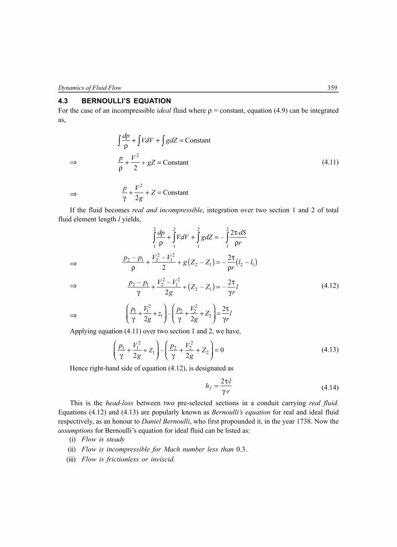
Dynamics of Fluid Flow 359
4.3 BERNOULLI’S EQUATIONFor the case of an incompressible ideal fluid where ρ = constant, equation (4.9) can be integratedas,
⇒2
Constant
Constant2
dp VdV gdZ
p V gZ+
+ + =ρ
+ =ρ
∫ ∫ ∫
(4.11)
⇒2
Constant2
p V Zg
+ + =γ
If the fluid becomes real and incompressible, integration over two section 1 and 2 of totalfluid element length l yields,
2 2 2 2
1 1 1 1
.2–dp dSVdV gdZr
τ+ + =ρ ρ∫ ∫ ∫ ∫
⇒ ( ) ( )2 2
2 1 2 12 1 2 1
– – 2– – –2
p p V V g Z Z l lr
+τ
+ =ρ ρ
⇒ ( )2 2
2 1 2 12 1
– – 2– –2
p p V V Z Z lg r
+τ
+ =γ γ
(4.12)
⇒2 2
1 1 2 21 2–
22 2
p V p Vz Z lg g r
τ+ + + + = γ γ γ Applying equation (4.11) over two section 1 and 2, we have,
2 21 1 2 2
1 2– 02 2
Zp V p V Z
g g+
+ + + = γ γ
(4.13)
Hence right-hand side of equation (4.12), is designated as.2
.flh
rτ=
γ (4.14)
This is the head-loss between two pre-selected sections in a conduit carrying real fluid.Equations (4.12) and (4.13) are popularly known as Bernoulli’s equation for real and ideal fluidrespectively, as an honour to Daniel Bernoulli, who first propounded it, in the year 1738. Now theassumptions for Bernoulli’s equation for ideal fluid can be listed as:
(i) Flow is steady(ii) Flow is incompressible for Mach number less than 0.3.(iii) Flow is frictionless or inviscid.

360 Mechanical Science-II
(iv) Flow is along a streamline.(v) No shaft work or transfer of heat between two pres-selected sections.
4.4 DIFFERENT HEADSIn the equation (4.11), each term on the left-hand side has the dimension of length. Thus it can betermed
pγ
= Pressure Head, 2
2V
g = Velocity Head, Z = Datum Head and sum of these three heads is
denoted by total head (H). So for an incompressible ideal fluid, H1 = H2 and for incompressiblereal fluid, H1 – H2 = hf . Again,
Pressure head . .. .
p p A lA l
= = =γ γ
pressure energy per unit weight
Velocity head 2 2 2. 1/ 2
.2 2V V m mV
g g m mg= = = = kinetic energy per unit weight
Datum head mgZZmg
= = = potential energy per unit weight
So, total head at any section of a conduit carrying incompressible fluid isH = [pressure energy + K.E. + P.E.] per unit weight.
A M
B
C
D
N
E
F
B
z
Hydraulic Grade Line(H.G.L.)
HeadLoss
Energy Grade Line (E.G.L)
hf
Datum Plane
V2
2g= Loss of Head at
SubmergedDischarge
C
V2
2g
p
T
Fig. 4.3
4.5 HYDRAULIC GRADE LINE (HGL) AND ENERGY GRADE LINE (EGL)Summation of pressure head and datum head at each section for a conduit of incompressible flow,if joined by an imaginary line is called hydraulic grade line (HGL) or piezometric head line(PHL) or static head (SH).
The locus of the total head along the length of the conduit is energy grade line (EGL).Sometimes it is also called total head line (THL). Illustration is given in Fig. 4.3.

Dynamics of Fluid Flow 361
4.6 MAJOR AND MINOR HEAD LOSSThe head loss in a conduit carrying incompressible fluid, as shown in equation (4.14) is termed asmajor head loss. This is the frictional head loss resulting from wall shear stress within the conduit.For a circular pipe flowing full, the expression for major head loss is
2. .
2fL Vh fD g
= (4.15)
Here L is the length and D is the diameter of the conduit and V is the velocity of flow. Thefactor f is known as friction factor. This equation is popularly known as Darcy-Weisbach equation.In a slightly different form, if D is replaced by hydraulic radius Rh, equation (4.15) becomes
2. .
2fh
L Vh fR g
= (4.16)
For a circular conduit flowing full, hydraulic radius Rh = D/4 and hence,2 2 24. . . . . .4
2 2 2f fL V L V L Vh f f C
D g D g D g= = = (4.17)
This is Fanning’s equation and Cf is known as coefficient of friction.Some gas and water pipelines include pipe bends, valves, T-joints and regions where cross
sectional area of the pipe changes abruptly. Local frictional loss at these points, including entranceand exit arise out of the effect of separation and are known as minor losses. It is expressed as
2.2fVh K
g= (4.18)
Here K is a constant bearing different value for commercial fittings, entrance and exit.
4.7 ABSOLUTE AND RELATIVE ROUGHNESSThe internal wall of the conduit or open channel cannot be perfectly smooth. Some protrusionsevenly or unevenly spaced and of variable heights are noticed inside the wall. Average height ofthese protrusions is defined as absolute roughness. It is symbolised by ε (epsilon) and expressedin the unit of length.
When absolute roughness is divided by the diameter of the pipe, the obtained quantity iscalled relative roughness (εr). Relative roughness εr = ε/D is a pure number.
4.8 REYNOLD’S NUMBERIn a fluid flow through a completely filled conduit, gravity force and capillarity have very negligibleeffect on flow pattern. Only the significant forces acting are inertia force and fluid friction due toviscosity. The ratio of inertia force to viscous force is called Reynold’s number (Re), in the honourof Osborne Reynold, who presented this through his experimental work in 1882. So,
eVD VDR ρ= =µ υ (4.19)

362 Mechanical Science-II
Reynold’s number is a quantity which determines whether the flow is laminar or turbulent.If it is less than 2000, the flow is laminar. Turbulent flow starts at 4000. In between laminar andturbulent flow, transition flow exists where 2000 < Re < 4000.
Both the friction factor and coefficient of friction are dependent on Reynold’s number (Re) andrelative roughness (εr) as f = φ1(Re, εr) and Cf = φ2(Re, εr). For a hydraulically smooth pipe, theeffect of relative roughness become negligible and friction factor depends only on Reynold’s number.
4.9 APPLICATION OF BERNOULLI’S EQUATIONBernoulli’s equation has wide variety of applications in the solution of a number of fluid flowproblems. This equation along with the equation of continuity serves very effectively for measurementof flow through pipes. Some flow measuring devices, otherwise known as flow-meters arediscussed here.
4.9.1 OrificemeterAn orifice is an opening (usually circular) in the wall of a tankor in a plate normal to the axis of the pipe, the plate being eitherat the end or at any intermediate location of the pipe. A standardsharp-edged orifice is shown in figure 4.4. Thickness of theorifice will be small enough, so that cannot affect the flow offluid through it. While the streamlines converge towardsapproaching an orifice, they continue to converge beyondupstream of the orifice, until reaching at section x-y where theybecome parallel. This section x-y bears a minimum area ordiameter of flow and the section is defined as vena contracta.Beyond vena contracta, streamlines diverge.
The performance of an orifice is related with three constants, namely, coefficient of contraction(Cc), coefficient of velocity (Cv), coefficient of discharge (Cd).
Coefficient of contraction is the ratio of the area of a jet at vena contracta (AC) to the areaof orifice (AO).
So, Cc
O
AArea at vena contractaCArea of orifice A
= = (4.20a)
Ideal velocity is one that would be attained in the jet at frictionless condition. Coefficientof velocity is the ratio of actual average velocity at vena contracta (VC) to ideal velocity (Vi).
So, Cv
i
VActual average velocityCIdeal velocity V
= = (4.20b)
Coefficient of discharge is the ratio of actual rate of discharge (Q) to ideal rate of discharge(Qi) at no-friction and no-contraction condition.
So, di
Actual rate of discharge QCIdeal discharge Q
= = (4.20c)
Fig. 4.4

Dynamics of Fluid Flow 363
The mutual relationship amongst these three coefficients can easily be established as
C C C C
d c vi O i O i
Q A V A VC C CQ A V A V
×= = = × = ×× (4.21)
An orifice or an orifice-plate, when used in a pipeline, is called an orificemeter, which providesa simple and cheap arrangement for measurement of flow through a pipe. An orificemeter fittedalong a horizontal pipe line is shown in Fig. 4.5, where section 1 is assumed at upstream side andsection 2 at vena contracta. Applying Bernoulli’s equation at these two section yields,
V2
2g
E.G.L.hf
V2
2g
H.G.L.p1
D1D2
D0
h
p3
p2
Fig. 4.5
2 2
1 1 2 2
2 2p V p V
g g+ = +
γ γ
⇒ 2 2
1 2 2 1– –2 2
p p V Vg g
=γ γ
(4.22)
If h be the piezometric head difference at these two sections, above equation can be writtenas,
2 2
2 1–2 2V Vh
g g=
⇒ 22 12V gh V= + (4.23)
This is the ideal velocity at section 2. Now the actual velocity at this section will be
22 12vV C gh V= + .
Again, 1 1 2 2 2. .
c OAV A V C A V= =
⇒ 1 21
. .Oc
AV C VA
= (4.24)

364 Mechanical Science-II
Hence,2
2 22 2
1
. .2 Ov c
AV C gh C VA
= +
(4.25)
⇒2
2 2 2 22
1
.1– 2Ov c v
AV C C C ghA
=
⇒2
2 2 22
1
.1 – 2Od v
AV C C ghA
=
[ ]d v cC C C= ×∵
⇒ 2 22
1
2
1–v
Od
ghV CACA
=
So, actual discharge
2 2 2 22
1
2. . . .
1c O c O v
Od
ghQ A V C A V C A CACA
= = =
−
22
1
2. .
1d O
Od
ghC AACA
=
− (4.26)
4.9.2 VenturimeterA venturimeter is a device which is used tomeasure both compressible as well asincompressible flow rate through a conduit.G.B. Venturi, the famous Italian physicistinvestigated its principle in about 1791 and itwas applied to measurement by ClemensHerschel in 1886. As shown in figure 4.6, aventurimeter attached along a horizontal pipeattached along a horizontal pipe consists of atube having constricted throat producingincreased velocity and reduced pressure,followed by a diverging part. ApplyingBernoulli’s equation in section 1 and 2,
2 21 1 2 2
2 2p V p V
g g+ = +
γ γ
Fig. 4.6
E.G.L
H.G.L
V2
2g
hf
p1
γ
h
1 220° 5°
Inlet Throat Diverging Cone
p2
γ
V2
2g

Dynamics of Fluid Flow 365
⇒ 2 2
2 1 1 2– –2 2V V p p h
g g= =
γ γ(4.27)
Here h is the piezometric head difference. Now ideal discharge
1 1 2 2iQ AV A V= =
⇒ 1 21 2
,i iQ QV VA A
= = (4.28)
Hence,
22 2
2 12 22 1
1 1– –2 2 2
iQV Vhg g g A A
= =
⇒ 1 2 2 21 2
2–ighQ A A
A A= (4.29)
So, actual discharge .d iQ C Q=
1 2 2 21 2
2–dghC A A
A A= (4.30)
If a U-tube manometer is employed to measure the difference in pressure head at section 1and 2, then for a definite level difference (say x) of manometric fluid in the two limbs, it is
1 2– –1mp p x γ
= γ γ γ
⇒ – 1mh x γ
= γ (4.31)
If an inverted U-tube manometer is used, then 1 – mh x γ
= γ (4.32)
4.10 STATIC PRESSURE AND STAGNATION PRESSUREThe static pressure is a parameter necessary for description of the state of a flowing fluid. Thehydrostatic pressure created by collision of molecules is known as static pressure in a fluid flow.When the fluid is at rest, this pressure is the same in all the directions.
While a fluid is flowing past an immersed body, there exists a particular streamline whichstrikes a points on the body, almost vertically. As a result, resultant velocity at that point reduces tozero, converting the entire kinetic energy of fluid to the increased pressure. This point on the body

366 Mechanical Science-II
is defined as stagnation point or point of stagnation(Fig. 4.7). The values of pressure, density andtemperature at stagnation point are defined asstagnation pressure (ps), stagnation density (ρs) andstagnation temperature (Ts). Stagnation pressure ispossible to occur only in the case of reversibleadiabatic process or isentropic process.
From the definition itself, it is evident that stagnationpressure is the algebraic summation of static pressure(po) and dynamic pressure, i.e.,
2
2s op p V
g= +
γ γ(4.33)
4.11 PITOT TUBEIt is a device used for measuring the velocity of flow at any pointin a pipe or an open channel. The principle of measurement offlow using pitot-tube was first adopted by Henri Pitot, a Frenchscientist in 1732, during velocity measurement in River Seine.
In its simplest form, a pitot-tube is a right-angled glass tube,long enough to neglect the effect of capillarity, shown in Fig. 4.8.One end of the tube is directed to face the flow while its other endis open to atmosphere. If the rise along fluid be h, then employingthe concept of stagnation pressure,
2
–2
s op p V hg
= =γ γ
⇒ 2V gh= (4.34)
This is the theoretical velocity through the pitot-tube. Actualvelocity of flow can be obtained by introducing the coefficientof pitot-tube, as
2ac pV C gh= (4.35)The value of Cp lies between 0.97 and 1.00, depending on
the degree of turbulence.Another arrangement of pitot-tube is shown in Fig. 4.9,
where piezometer at section a measures static pressure andpitot-tube at section b measures total pressure or stagnationpressure.
Streamlines
BODY
Streamlines
S
Fig. 4.7
Fig. 4.8
a
2g
v
Stagnation Point
po
S
v2
b
2g
v
Stagnation Point
po
a
S
v2
Fig 4.9

Dynamics of Fluid Flow 367
The arrangement of measurement of static pressure and total pressure when are combinedinto one instrument, it is called pitot-static tube. A particular type of pitot-tube is Prandtl’s tubeor Prandtl’s static tube. Schematic views of normal pitot-static tube and Prandtl’s tube are givenin Fig. 4.10 and 4.11.
Small Holes on BothSides of Outer Tube
Total Head Static Head
Fig. 4.10
Fig. 4.11
Multiple Choice Questions
1. Bernoulli’s equation is obtained by the integration of(a) Navier-Stokes equation (b) Reynold’s equation(c) Euler’s equation (d) none of these
2. Bernoulli’s equation written in the form 2
2p V z
g+ +
γ = constant, represents total energy per unit
(a) volume (b) mass(c) weight (d) none of these

368 Mechanical Science-II
3. Piezometric head is the summation of(a) velocity head and datum head (b) pressure head and velocity head(c) velocity head in the direction of flow (d) none of these
4. HGL indicates the variation of(a) total energy in direction of flow (b) piezometric head in direction of flow(c) velocity head in direction of flow (d) pressure head in direction of flow
5. EGL always lies(a) above (b) below(c) parallel to (d) along HGL
6. EGL in pipe flow is a graphical representation of Bernoulli’s equation and measured above(a) centerline of pipe (b) top of the pipe(c) arbitrary horizontal datum (d) top of piezometer tube
7. Total energy represented by Bernoulli’s equation has the unit(a) kgm/m (b) Nm/N(c) kgm2/s (d) kgm/s
8. Stagnation point is a point where(a) pressure is zero (b) total energy is zero(c) velocity of flow reduces to zero (d) total energy is maximum
9. Pitot-tube is an instrument for measuring(a) pressure of flow (b) velocity of flow(c) discharge of fluid (d) total energy
10. Stagnation pressure is the sum of(a) vacuum pressure and static pressure (b) static pressure and dynamic pressure(c) dynamic pressure and vacuum pressure (d) none of these
11. Venturimeter is used to measure(a) piezometric head (b) velocity head(c) discharge through a pipe (d) none of these
12. A venturimeter is preferable to orificemeter, because(a) it is cheaper (b) it is more convenient to use(c) energy loss is less (d) it requires smaller length
13. Cd of an orificemeter is always(a) greater than Cc (b) equal to Cc
(c) equal to Cv (d) less than Cc
14. Which of the following devices is used for measuring pipe flow?(a) mouthpiece (b) notch(c) weir (d) orificemeter

Dynamics of Fluid Flow 369
15. In orifice flow, vena contracta represents(a) jet has maximum flow area(b) pressure is above atmosphere(c) jet area is minimum and streamline are parallel(d) pressure is below atmosphere
16. Reynold’s number is the ratio of(a) inertia force and gravity force (b) inertia force and viscous force(c) pressure force and inertia force (d) none of these
17. Value of Reynold’s number below which flow through closed conduit will be laminar is(a) 5,000 (b) 20,000(c) 2,000 (b) 3,000
18. Reynold’s number is expressed as
(a) VDρµ
(b)2V Dρ
(c)2V Dρ
υ(d)
2 2V Dυ
19. Energy loss in pipeline is due to(a) viscous action only (b) surface roughness only(c) pipe wall friction and viscous action (d) turbulent shear stress alone
20. Minor loss in pipe flow are those(a) which have small magnitude(b) which are caused by local disturbances caused by valves, bends etc.(c) caused by friction(d) none of these.
21. The unit of relative roughness is(a) m (b) N(c) kg (d) dimensionless, pure number
22. The parameters on which the friction factor is dependent are(a) relative roughness and Reynold’s number (b) absolute roughness and viscosity(c) Reynold’s number and specific gravity (d) none of these
23. Coefficient of discharge (Cd) in terms of Cc and Cv are(a) Cd = Cc × Cv (b) Cd = Cc /Cv
(c) Cd = Cv /Cc (d) none of these
24. Bernoulli’s equation can be applied to(a) venturimeter (b) pitot-tube(c) orificemeter (d) all of these

370 Mechanical Science-II
25. For hydrodynamiclly smooth boundaries, friction factor for turbulent flow is(a) dependent on Reynold’s number(b) constant(c) function of Reynold’s number and relative roughness(d) dependent on roughness only
26. The losses in fluid flow is more in(a) laminar flow (b) turbulent flow(c) transition flow (d) critical flow
27. HGL is(a) always above centerline of pipe (b) always sloping downward in sloping direction(c) never above EGL (d) none of these
28. Bernoulli’s equation is based on(a) principle of conservation of energy (b) principle of conservation of mass(c) principle of conservation of momentum (d) none of these
29. Euler’s equation of motion can be integrated when it is assumed that(a) continuity equation is satisfied(b) fluid is incompressible(c) velocity potential exists and density is constant(d) flow is irrotational and incompressible
30. Specify, which of the following must be fulfilled by the flow of any fluid, real or ideal, laminar orturbulent(a) Newton’s law of viscosity (b) continuity equation(c) velocity at boundary must be zero (d) velocity normal to solid boundary is zero
31. Head loss in turbulent flow of pipe(a) varies directly as the velocity(b) varies directly as the square of the velocity(c) varies inversely as the square of the velocity(d) varies approximately as the square of the velocity
32. In laminar flow through a closed conduit, discharge varies(a) linearly as the viscosity (b) as the square of the radius(c) inversely as the pressure drop (d) inversely as the viscosity
33. For laminar flow in a pipe of circular cross section Darcy friction factor is(a) independent of Reynold’s number and independent of pipe wall friction(b) inversely proportional to Reynold’s number and independent of pipe wall roughness(c) directly proportional to Reynold’s number and independent of pipe wall roughness(d) inversely proportional to Reynold’s number and directly proportional to pipe wall roughness

Dynamics of Fluid Flow 371
34. From the following statement, choose the correct one related to Bernoulli’s equation(a) equation is valid for steady flow of an incompressible ideal or real fluid along a streamline(b) energy equation for the flow of a frictionless fluid of constant density along a streamline with
gravity as the only body force(c) equation is derived from dynamic consideration involving gravity, viscous and inertia forces(d) constant in the equation varies across streamlines if flow is irrotational
35. Euler’s equation of motion is a(a) statement of energy balance(b) preliminary step to derive Bernoulli’s equation(c) statement of conservation of momentum for a real, incompressible fluid(d) statement of conservation of momentum for an inviscid fluid flow
36. Study of fluid motion with forces causing flow is known as(a) kinematics of fluid flow (b) kinetics of fluid flow(c) statics of fluid flow (d) none of the above
37. The term V2/2g in Bernoulli’s equation is known as(a) kinetic energy (b) pressure energy(c) kinetic energy per unit weight (d) none of these
38. Difference of pressure head (h) measured by mercury-oil differential manometer is given by
(a) 1– g
o
Sh x
S
= (b) ( )–g oh x S S=
(c) ( )–o gh x S S= (d) –1g
o
Sh x
S
=
39. Ratio of area of jet at vena-contracta to area of orifice is known as(a) coefficient of discharge (b) coefficient of velocity(c) coefficient of contraction (d) coefficient of viscosity
40. Ratio of actual velocity at vena-contracta to ideal velocity(a) coefficient of discharge (b) coefficient of velocity(c) coefficient of contraction (d) coefficient of viscosity
Answers
1. (c) 2. (c) 3. (c) 4. (b) 5. (a) 6. (c) 7. (b) 8. (c) 9. (b) 10. (b)11. (c) 12. (c) 13. (d) 14. (d) 15. (c) 16. (b) 17. (c) 18. (a) 19. (c) 20. (b)21. (d) 22. (a) 23. (a) 24. (d) 25. (a) 26. (b) 27. (c) 28. (a) 29. (c) 30. (b)31. (d) 32. (d) 33. (b) 34. (a) 35. (a) 36. (b) 37. (c) 38. (d) 39. (c) 40. (b)

372 Mechanical Science-II
True or False
1. Friction factor in the Darcy-Weisbach equation is given by 20 / 0.5f V= τ ρ
2. Minor losses can be expressed either as fraction of kinetic energy or equivalent length.3. HGL cannot have positive slope.4. Concept of hydraulic radius is relevant to both laminar and turbulent flow.5. In ageing of pipes, friction factor increases linearly with tie.6. The term 2 / 2V g in Bernoulli’s equation is known as kinetic energy per unit weight.7. Orificemeter can also be used for measuring flow of an open channel.8. In orificemeter, coefficient of discharge is always less than unity.9. At stagnation point, velocity of flow is maximum.
10. In a hydraulically smooth pipe, Reynold’s number is not dependent on relative roughness.
Answers1. False 2. True 3. False 4. False 5. False6. True 7. False 8. True 9. False 10. True
NUMERICAL EXAMPLES
EXAMPLE 1A vertical venturimeter shown in figure, has an area ratio 5, with throat diameter 1 cm. When oil of
specific gravity 0.8 flows through it, mercury in the differential gauge indicates a difference in height of 12 cm.Find discharge through venturimeter.
SOLUTION
Difference in piezometric head
1 21 2
oil– – 1mp pZ Z x
γ+ + = γ γ γ
⇒13.5960.12 –1 1.919 m
0.8h = =
But, 1 25 andA A=
2 –5 22 0.01 7.8539 10 m
4A π
= × = ×
So, actual discharge through venturimeter, from equation (4.30)
1 2 2 21 2
2–dghQ C A A
A A=
( ) ( ) ( )2–5
2 2–5 –5
2 9.807 1.9190.98 5 7.8539 105 7.8539 10 – 7.8539 10
× ×= × × ×× × ×
–4 34.819 10 m /s= ×

Dynamics of Fluid Flow 373
EXAMPLE 2A pitot-static tube is used to measure velocity of water in a pipe. The stagnation pressure head is
8 m and static pressure head is 6 m. Calculate the velocity of flow, assuming coefficient of tube 0.98.
SOLUTION
Referring to equation (4.33)
2– 8 – 6 2
2s op pV
g= = =
γ γ
⇒ 6.263V =
Introducing discharge coefficient, actual velocity of flow 0.98 6.263 6.137 m/s= × =
EXAMPLE 3A vertical pipe of 1 m diameter and 20 m length has a pressure head of 5.5 m of water at the upper
end. When water flows through the pipe at an average velocity of 4.5 m/s, the head loss due to friction is 1.2 m.Find the pressure at the lower end of the pipe, when the flow is (a) upward (b) downward.
SOLUTION
(a) For upward flow; upper section is considered section 2–2 and lower section is 1–1
Here, ( )21 2 2 15.5 m, 4.5 m/s, 1.2 m, – 20 mf
pV V h Z Z= = = = =
γ
Applying Bernoulli’s equation2 2
1 1 2 21 22 2 f
p V p VZ Z hg g
+ + = + + +γ γ
⇒ ( )1 22 1– 5.5 20 1.2 26.7 mf
p pZ Z h= + + = + + =
γ γ(a) For downward flow; upper section is 1–1 and lower section is 2–2.
Here, ( )11 2 1 25.5 m, 4.5 m/s, 1.2 m, – 20 mf
pV V h Z Z= = = = =
γApplying Bernoulli’s equation
2 21 1 2 2
1 22 2 fp V p VZ Z h
g g+ + = + + +
γ γ
⇒ ( )2 11 2– – 5.5 20 – 1.2 24.3 mf
p pZ Z h= + = + =
γ γ
EXAMPLE 4A siphon is shown in the figure. A is 1 m above water level, indicates point 1. Bottom of siphon is
below A. Assuming friction to be negligible, determine velocity of flow at outlet and the pressure at A.

374 Mechanical Science-II
SOLUTION
Applying Bernoulli’s equation at 1 and 2
2 21 1 2 2
1 22 2p V p VZ Z
g g+ + = + +
γ γ
Here, 1 2–1m, – 8 m,Z Z= = atmospheric pressure 1 2 0p p
= = =γ γ
and cross-sectional area of the tank is
much larger than of the tube, so, 1 2.V V<<
Hence,2
21 22
VZ Zg
= +
⇒ 2 11.717 m/s AV V= ≈Again, applying Bernoulli’s equation at 1 and A
2 21 1
12 2A A
Ap V p VZ Z
g g+ + = + +
γ γ
But, 11 –1 m, 0, 0A
pZ Z= = =
γ
Hence,2
1 2A Ap VZ
g= +
γ
⇒ – 7.999 mAp=
γSo, at A, the pressure is negative, i.e., suction pressure.
EXAMPLE 5Referring to the figure of siphon carrying oil
(0.8), calculate (a) velocity of oil through siphon(b) pressure at A, B and C. (c) maximum height of C can beaccommodated above the level in the vessel(d) maximum vertical depth of right limb of siphon. Takevapour pressure at working temperature 29.5 kPa andatmospheric pressure 101 kPa.
SOLUTION
(a) Applying Bernoulli’s equation at 1 and D, where
1 1.5 4 5.5 m, 0,DZ Z= + = =
atmospheric pressure = 110, and ,D
Dp p
V V= = <<γ γ
we have2
1 2DVZg
=
⇒ 10.386 m/sDV =
C
B
A
D
H
h1.5 m
4 m
1.5 m
1

Dynamics of Fluid Flow 375
(b) As cross-section of siphon tube does not change, velocity of oil through siphon will be10.386 m/sB DV V= = .
Here ( )1 1.5 1.5 m of oil gauge and 4 m and 0AA B A
p pZ Z V= + = = = =
γ γ.
Applying Bernoulli’s equation at A and B2
2A B Bp p V
g= +
γ γ
⇒ ( )210.3861.5 – – 4.0 m of oil gauge
2 9.807Bp
= =γ ×
So, absolute pressure at 101 – 4 0.8 9.807 69.62 kPaB = × × =
Absolute pressure at 101 1.5 0.8 9.807 112.768 kPaA = + × × =Applying Bernoulli’s equation between 1 and C
221 1
12 2C C
Cp Vp V Z Z
g g+ + = + +
γ γ
⇒ ( ) ( )210.3865.5 – 7 – – 7 m of oil gauge
2 9.807Cp
= =γ ×
Absolute pressure at 101 – 7 0.8 9.807 46.08 kPaC = × × =(c) At maximum height of C, the pressure will be equal with vapour pressure. Considering absolute pressure,Bernoulli’s equation yields
221 1
12 2Vap C
Cp Vp V Z Z
g g+ + = + + ′
γ γ
⇒ ( )3 3 2
3 3101 10 29.5 10 10.3865.5 5.5
2 9.8070.8 9.807 10 0.8 9.807 10h× ×
+ = + + +×× × × ×
⇒ 3.614 mh =(d) Let H be the value of maximum depth at which pressure at C equals to vapour pressure. Now applying
Bernoulli’s equation at 1 and D, 2DV gH=Again, Bernoulli’s equation at 1 and C, considering absolute pressure,
231
329.5 10 1.5
20.8 9.807 10Dp V
H Hg
×+ = + + +
γ × ×
⇒ H = 3 3
3 3101 10 29.5 10– – 1.5 7.613 m.
0.8 9.807 10 0.8 9.807 10× ×
=× × × ×

376 Mechanical Science-II
EXAMPLE 6Water flows through a 300 × 150
venturimeter @0.037 m3/s and differentialgauge is deflected 1 m. Specific gravity of thegauge liquid is 1.25. Determine coefficient ofdischarge of the meter.
SOLUTION
Applying Bernoulli’s equation between A andB, where ZA = 0 = ZB yields
2 2
2 2A A B Bp V p V
g g+ = +
γ γ (a)
Applying equation of continuity between A and B,
BA B
A
AV V
A
=
⇒ 2
2 2BA B
A
AV VA
= (b)
Substitution (b) into (a), we obtain ( )
2
2
2 –
1–
A BB
B
A
g p pV
AA
=
γ
So, actual discharge ( )
2
2
2 –
1–
A Bd B B d B
B
A
g p pQ C A V C A
AA
= =
γ
(c)
Again from differential gauge,
( ) ( )– – 1.25 1 1A Bp pZ Z× + + =
γ γ
⇒ – 0.25A Bp p=
γ γSubstituting in (c) we obtain,
24
4
2 9.807 0.25.0.037 0.154 0.151–
0.3
d B B dC A V C π × ×= =
⇒ Cd = 0.9155
300 mm dia. z
C
1 mD
C'300 mm dia.
150 mm dia.
BA

Dynamics of Fluid Flow 377
EXAMPLE 7A venture section of a pipe flow is shown in the figure. Derive an expression for V2, just sufficient
to cause the reservoir liquid to rise in tube upto section 1.
Water
Water
D2
V2
V1
p = p2 atm
1
D1
patm
h
SOLUTION
For the liquid to rise through the tube, atm 1–p p h≥ γ (a)
Using continuity equation, 2
2 21 2 2
1 1
A DV V VA D
= =
Applying Bernoulli’s equation at 1 and 2, while Z1 = Z2
2 2 2atm1 1 2 2 2
2 2 2pp V p V V
g g g+ = + = +
γ γ γ
⇒( )2 2 421 2 2 2
atm 11
12 2
V V V Dp pg g D
− − = γ = γ − (b)
Comparing the two values, given in equations (a) and (b)
422 2
1–1
2V D h
g D
γ ≥ γ
⇒ 2 42
1
2
– 1
ghVDD
=
EXAMPLE 8Air flows through a duct and Pitot-static tube measuring the velocity is attached to a differential
manometer containing water. If deflection of the manometer is 100 mm, calculate air velocity, assumingρair = 1.22 kg/m3 and coefficient of tube be 0.98.

378 Mechanical Science-II
SOLUTION
Now, 3
water0.1 9.807 10– 81.967 m of air
1.22 9.807s op P
h × ×= = =
γ γ ×Applying equation (4.35)
2 0.98 2 9.807 81.967 39.294 m/sac pV C gh= = × × =
EXAMPLE 9Water flows at a velocity of 1.417 m/s. A differential gauge which contains a liquid of specific
gravity 1.25 is attached to a Pitot-static tube. What is the deflection of the gauge fluid? Coefficient of the tubeis 1.
SOLUTION
Following equation (4.35)
2p wV C gh=
⇒ 1.417 1 2 9.807 wh= × ×
⇒ 0.1023 m of waterwh =From manometric equation of differential gauge,
– 1mw m
wh h
γ= γ
⇒ 1.250.1023 – 1
1 mh =
⇒ 0.4092 mmh =
EXAMPLE 10A vertical venturimeter carries a liquid of sp.gr. 0.8. Inlet and outlet diameters are 150 mm and 75 mm
respectively. Pressure connection at throat is 150 mm above inlet. If actual flow rate is 40 lit/s andCd = 0.96, calculate (a) pressure difference between inlet and throat (b) difference in mercury level in a U-tubemanometer connected between inlet and throat.SOLUTION
(a) Let inlet is section 1 and throat is section 2. Here,
2 21 0.15 0.01767 m
4A π
= = , 2 –3 22 0.075 4.4178 10 m
4A π
= = × ,
3 –6 340 10 10 m /sQ = × × , 0.96dC = .
Substituting in 1 2 2 21 2
2–dghQ C A A
A A= we can obtain, h = 4.25 m
So, piezometric head difference
1 2
1 2–p ph Z Z
= + + γ γ

Dynamics of Fluid Flow 379
⇒ ( )1 24.25 – 0 – 0.15p p = + γ γ
⇒ 1 2– 4.4p p
=γ γ
⇒ 1 2– 4.4 0.8 9.807 34.52 kPap p = × × =
(b) Again using equation (4.31)
0.15 – 1mmh h
γ+ = γ
⇒ 13.5964.4 – 10.8 mh =
⇒ 0.275 mmh =
EXAMPLE 11The head loss from the entrance to the throat of a 254 × 127 venturimeter is 1/6th times the
throat velocity head. If mercury in the differential gauge attached to the meter deflects 101.6 mm, what is theflow of water through the venturimeter?SOLUTION
Difference in piezometric head
13.596– 1 – 1 0.1016 1.2797 m
1m
mh h γ = = = γ
Being horizontal, Bernoulli’s equation applied at entrance and throat yields
2 2 2 2
1 1 2 2 2 2 212 2 2 6 2f
p V p V p V Vhg g g g
+ = + + = + +γ γ γ
⇒ 2 2
1 2 2 1– 1.167 –2 2
p p V Vg g
=γ γ
⇒ 2
2 22 1
1 11.2797 1.167 –2Q
g A A
=
( )2
32 4 4
1 1.167 1– 0.06 m /s2 9.807 0.127 0.254/ 4
Q = = × π
[Here Cd is not introduced in the computation, because its effect has already been considered in terms ofheadloss]
EXAMPLE 12The air supply to an oil-engine is measured by inducting air directly from the atmosphere into a
large reservoir through a sharp edged orifice of 50mm diameter. Pressure difference across the orifice is measured

380 Mechanical Science-II
by an alcohol manometer set at a slope of θ = sin–1 (0.1) to the horizontal. Calculate the volume flow rate of airif manometer reading is 271mm. Consider sp.gr. of alcohol is 0.8, Cd = 0.62, Cc = 0.6, atm.pr. = 775 mm of Hg, atm.temp. = 15.8°C.
SOLUTION
Vertical height of manometric fluid . sin 0.271 0.1 0.0271 malh h= θ = × =
Equivalent height of air column
3
air0.8 10– 1 –1 0.0271 17.787 m
1.217m
alh h γ ×= = = γ
Here, V1 = 0, as section 1 is open to atmosphere, and
2
2 air 1 air2 2dv
c
CV C gh V gh
C= + =
0.62
2 9.807 17.7870.6
= × ×
= 19.3 m/sApplying equation of continuity, flow rate
2 32 2 2 0.6 0.05 19.3 0.02273 m /s
4c OQ A V C A V π= = = × × × =
EXAMPLE 13What is the size of an orifice required to discharge 0.016 m3/s of water under a head of 8.69 m, while
Cd = 1.0.
SOLUTION
Velocity of flow
2 2 9.807 8.69 13.055 m/sV gh= = × × =Applying equation of continuity, c/s area
6 20.01610 1225.58 mm
13.055QAV
= = × =
EXAMPLE 14Flow of air at 49°C is measured by a Pitot-static tube. If the velocity of air is 18.29 m/s and the
coefficient of tube is 0.95, what differential reading will be shown in a water manometer? Assume density ofair to be constant at 1.2 kg/m3.
SOLUTION
Applying equation (4.35)
air2pV C gh=
⇒ air18.29 0.95 2 9.807 h= × ×
⇒ air 18.89792 mh =

Dynamics of Fluid Flow 381
Again from equation of differential manometer
airair
1wwh h
γ= − γ
⇒ 31018.89792 1
1.2 wh
= −
⇒ hw = 0.022704 m = 22.704 mm
EXAMPLE 15A pump is installed in a pipeline, 5 cm dia., carrying oil of sp.gr. 0.83. It returns the oil to a 5 cm dia.
pipe at the same elevation with a pressure increase of 1.4 kg/cm2. Quantity of oil flowing in the pipeline is10 lit/s. The motor driving the pump delivers 3.8 metric H.P. to the pump shaft. Calculate loss of energy in thepump in kg-m/kg and kg-m/s.
SOLUTION
Applying Bernoulli’s equation at sections 1 and 2,
2
1 112
p V Zg
+ + +γ
energy from pump
= 2
2 222
p V Zg
+ + +γ
losses in pump
Here, 1 2 1 2 2 1, andZ Z V V p p= = >
1 2energy from pump losses in pumpp p
+ = +γ γ
⇒ 1 2losses in pump – energy from pumpp p = + γ γ
So, 2
31.4 100– energy from pump10 0.83
×= +
×
– 16.87 m energy from pump= +
Now, energy from pump 3.8 75 285 kg m/s= × = ×Energy from pump per kg of oil
= 3 –6 3285 34.3 kgm/kg
10 10 10 0.83 10=
× × × ×So, losses in pump
( )–16.87 34.3 17.43 kgm/kg of oil= + =
( )3 –6 3or, 17.43 10 10 10 0.83 10 144.7 kgm/s× × × × × =
Pump
1 2
1 2

382 Mechanical Science-II
EXAMPLE 16Water moves steadily through turbine @ 0.23
m3/s. Pressure at (1) and (2) are 186.4 kN/m2 and19.6 kN/m2 respectively. Neglecting transfer of heat,determine the H.P. delivered to the turbine from water.
SOLUTION
Here,
2 2 2 21 20.2 0.03141 m , 0.4 0.12566 m
4 4A Aπ π
= = = =
So,
1 20.23 0.23
7.322 m/s, 1.83 m/s0.03141 0.12566
V V= = = =
Applying Bernoulli’s equation at sections 1 and 2
2 2
1 1 2 21 22 2
p V p VZ Z Hg g
+ + = + + +γ γ
Head delivered to the turbine
( )2 2
1 2 1 21 2
– ––
2p p V VH Z Z
g= + +
γ
( ) ( )
3 2 2
3
186.4 19.6 10 7.322 – 1.831.3 – 0 24.8675 m2 9.8079.807 10
+= + + =
××H.P. delivered to turbine
310 0.23 24.8675 76.26 metric H.P.
75 75QHγ × ×
= = =
EXAMPLE 17A venturimeter with 30 cm diameter inlet and 15 cm throat is used for measuring flow of oil of
sp.gr. 0.9. The oil-mercury differential gauge shows a reading of 33 cm. Assuming the coefficient of meter 0.98,calculate the discharge.
SOLUTION
Here, 2 2 2 21 20.3 0.07068 m , 0.15 0.01767 m
4 4A Aπ π
= = = =
Again, oiloil
13.596– 1 – 1 0.33 4.655 m0.9
mmh h
γ = = = γ
To obtain the discharge through venturimeter, substitute values in 1 2 2 21 2
2–dghQ C A A
A A=
which is 0.17089 m3/s.
Turbine1
2
d = 20 cm1
1.3 m
d =40 cm2

Dynamics of Fluid Flow 383
EXAMPLE 18A 20 cm waterpipe has in it a venturimeter of throat
diameter 12.5 cm as shown in the figure, which is connected to amercury manometer showing a difference of 86.5 cm. Find thevelocity in the throat and the discharge.
SOLUTION
Applying Bernoulli’s equation in sections 1 and 2,
2 2
1 1 2 212 2
p V p V yg g
+ = + +γ γ (a)
From the principle of manometer
( )1 22 2 10.865 – 0.865 13.596 – –
p py y y+ + × =
γ γ
⇒ 1 2110.8955
p py= + +
γ γ (b)
Substituting (b) in (a)
2 2
2 1 2 21 110.8955
2 2p V p Vy y
g g+ + + = + +
γ γ
⇒ 22 2 2
2 1 2 2
110.8955 10.8955
2 2 2V V V A
g g g A
= + = +
= 42
2 0.12510.89552 0.2V
g +
⇒ 2
20.8474 10.89552V
g=
⇒ 2 15.88 m/sV =
Discharge 2 32 2 0.125 15.88 0.1948 m /s
4Q A V π
= = × × =
EXAMPLE 19A venturimeter is installed in a pipeline of 30 cm diameter. The throat-pipe diameter ratio is 1:3. The
pressure in the pipeline is 137.7 kN/m2 and the vacuum in the throat 37.5 cm of mercury. If 4% of the differentialhead is lost between gauges, find the flow in the pipeline.
SOLUTION
Let us consider pipeline as section 1 and throat section 2.
So, 2
2 1
1 2
1 13 9
A VA V
= = =
⇒ 1 2 2 19 and 9A A V V= =
2
12.5 cm
20 cmDatum
y1
y2
Hg
1
86.5 cm

384 Mechanical Science-II
Again, 22 – 0.375 13.596 9.807 – 50 kN/mp = × × =
Now, 2 2
1 1 2 2
2 2 fp V p V h
g g+ = + +
γ γ
2
2 2 1 20.042
p V p pg
= + + − γ γ γ
1 24% of –fp ph
= γ γ
∵
⇒ 2 2
1 2 2 10.962 2
p p V Vg g
− = − γ γ
⇒( )2 2
1 19137.7 500.969.807 2 9.807 2 9.807
V V+ = − × ×
⇒ 1 2.122 m/sV =
So, discharge 2 31 1 0.3 2.122 0.1499 m /s
4Q AV π
= = × × =
EXAMPLE 20At a point in the pipeline where diameter is 20 cm, velocity of water is 4 m/s and pressure
3.5 kg/cm2. At a point 15 m downstream, diameter reduces to 10 cm. Calculate pressure at this point if pipe isvertical with (a) downward flow and (b) upward flow.
SOLUTION
Considering no head loss between 1 and 2, velocity at 2 is
21
2 12
0.24 16 m/s
0.1A
V VA
= = × =
(a) Here, 2 2
1 1 2 21 22 2
p V p VZ Zg g
+ + = + +γ γ
⇒ 4 2 2
23.5 10 4 1615 01000 2 9.807 2 9.807
p×+ + = + +
× γ ×
⇒ 22 37.7638 m of water 3.77638 kg/cmp
= =γ
(b) Here, 2 2
1 1 2 21 22 2
p V p VZ Zg g
+ + = + +γ γ
⇒ 4 2 2
23.5 10 4 160 151000 2 9.807 2 9.807
p×+ + = + +
× γ ×
⇒ 22 7.7638 m of water 0.77638 kg/cmp
= =γ
2 21 1
15 m
1 12 2
15 m
(b)Upward Flow
(a)Downward Flow

Dynamics of Fluid Flow 385
EXAMPLE 21The velocity of water in pipeline was measured with Pitot-static tube. The difference of head at the
centre of the pipe was 89 mm of water. If mean velocity of water is three-fourth the velocity at the centre,determine rate of flow. Diameter of the pipe is 280 mm. Take Cp = 0.99.
SOLUTION
Velocity at the centre of the pipe
2 0.99 2 9.807 0.089 1.308 m/spV C gh= = × × =
Mean velocity 3
1.308 0.981 m/s4
= × =
Rate of flow 2 30.28 0.981 0.0604 m /s4
Q AV π= = × =
EXAMPLE 22Adjacent figure shows a siphon
discharging oil (sp.gr. = 0.84) from a reservoir intoopen air. If the velocity of flow in the pipe is V, thehead loss from point 1 to 2 is 2V 2/2g, and that frompoint 2 to 3 is 3V 2/2g, determine the volume flow ratein the siphon pipe and absolute pressure at point 2.Assume an atmosphere pressure 101.358 kPa.
SOLUTION
Different head losses between sections are asfollowing:
2 2
1–2 2–32 3, and2 2V Vh hg g
= =
∴ 2
1–3 1–2 2–352Vh h hg
= + =
Applying Bernoulli’s equation between sections 1 and 3
22
3 31 11 3 1–32 2
p Vp V Z Z hg g
+ + = + + +γ γ
Here, V1 = 0, V2 = V3 = V and being open to atmosphere, p1 = p3 = 0
So, ( )2
2 54.6 – 1.5 02 2V V
g g= + +
⇒ V = 3.183 m/s = V2 = V3
Volume flow rate 2 33 3 0.075 3.183 0.014 m /s
4Q A V π
= = × × =
1.5 m
4.6 m
7.5 cm Diameter Pipe
2
3
1
Oil (s.g. = 0.84)

386 Mechanical Science-II
Applying Bernoulli’s equation between sections 1 and 2
2 2
1 1 2 21 2 1–22 2
p V p VZ Z hg g
+ + = + + +γ γ
⇒ ( )2 2
2 3.183 3.1834.6 –1.5 4.6 22 9.807 2 9.807
p= + + +
γ × ×
⇒ 2 –3.049 m of oilp
=γ
⇒ 2 gauge (–3.409 0.84 9.807) – 25.117 kPap = × × =
⇒ ( )2 absolute 101.358 – 25.117 76.241 kPap = =
EXAMPLE 23Compute the ideal flow rate through the
pipe system shown in the figure.
SOLUTION
Applying Bernoulli’s equation between 1 and 2 andassuming no head loss,
2 2
1 1 2 21 22 2
p V p VZ Zg g
+ + = + +γ γ
⇒ 2
1 1 20.6 sin 30 0 02
p V pg
+ + ° = + +γ γ
⇒ 2
1 2 1– – 0.32V p p
g
= γ γ Again from the equation of manometer,
1 2–1.2 sin 60p p
° =γ γ
⇒ 1 2– 1.0392p p
= γ γ Combining these two results, we obtain
2
1 1.0392 – 0.3 0.73922V
g= =
⇒ 1 3.807 m/sV =
Ideal flow rate 2 31 1 0.2 3.807 0.1196 m /s
4Q AV π
= = × =

Dynamics of Fluid Flow 387
EXAMPLE 24The flow from two reservoirs mixes together
and flows through a common pipe. Both reservoir containsame liquid and open to atmosphere. Neglecting frictionalloss, find flow rate through common pipe.
SOLUTION
Applying Bernoulli’s equation between 1 and 22 2
1 1 2 21 22 2
p V p VZ Zg g
+ + = + +γ γ
⇒ 2
atm 2 210 0
2p p Vh
g+ + = + +
γ γ
⇒ 2
atm 2 21 2
p p Vhg
+ = +γ γ
(a)Applying Bernoulli’s equation between 3 and 4, in the similar way,
⇒ 2
atm 4 42 2
p p Vhg
+ = +γ γ (b)
Applying Bernoulli’s equation between 5 and 6, in the similar way
2 2
5 5 6 65 62 2
p V p VZ Z
g g+ + = + +
γ γ
⇒ ( )2 2
5 5 atm 630 –
2 2p V P V
hg g
+ + = + +γ γ
⇒ 5 atm
3–p P
h=γ γ (c)
As points 2,4 and 5 lie on the boundary of control volume, as shown in the figure, p2 = p4 = p5 (d)
Substituting (c) and (d) into (a),
2
atm atm 21 3–
2P P Vh h
g+ = +
γ γ
⇒ ( )2 1 32V g h h= + (e)Substituting (c) and (d) into (b),
2
atm atm 42 3–
2P P Vh h
g+ = +
γ γ
⇒ ( )4 2 32V g h h= + (f)
Reservoir 2
3
4
5
6
1 h2
d2
h3d3
d1
Reservoir 1
h1
ControlVolume
Datum forPotentialEnergy
patm
2
patm

388 Mechanical Science-II
10 cm dia. 6 cm dia.
1
2y
8 cm
1
2
So, flow through common pipe 1 2 1 2 2 4Q Q Q AV A V= + = +
( ) ( )2 21 1 3 2 2 32 2
4d g h h d g h hπ = + + +
2 21 1 3 2 2 32
4g d h h d h hπ = + + +
EXAMPLE 25In the figure, the fluid
flowing is air (γa = 12 N/m3) and themanometric fluid is Meriam Red Oil(sp. gr. = 0.827). Assuming no loss,compute the flow rate.
SOLUTION
Applying Bernoulli’s equation betweensections 1 and 2,
2 2
1 1 2 21 22 2a a
p V p VZ Z
g g+ + = + +
γ γ
⇒ 2
1 2 20 0 02a a
p p Vg
+ + = + +γ γ [ ]1 2Assuming V V
⇒ 2
1 2 2–2a a
p p Vg
=γ γ (a)
From the equation of manometer,
31 28 1
– 0.827 10 9.807 0.08 –100 12 100a a
p py y+ + × × × × = γ γ
⇒ 1 2– 53.989a a
p p=
γ γ(b)
Solving (a) and (b), 2
2 53.9892V
g=
⇒ 2 32.541 m/sV =
Flow rate 2 32 2 0.06 32.541 0.092 m /s
4Q A V π
= = × =
EXAMPLE 26Inlet and throat diameters of a horizontal venturimeter are 30 cm and 10 cm respectively. The liquid
flowing through the venturimeter is water. Pressure intensity at inlet is 13.734 N/cm2, while vacuum pressure at

Dynamics of Fluid Flow 389
throat is 37 cm of mercury. Find flow rate, assuming 4% of the differential head is lost between inlet and throat.Find also value of Cd.
SOLUTION
Now, 2 2 2 –3 21 20.3 0.07068 m , 0.1 7.854 10 m
4 4A Aπ π
= = = = ×
21 13.734 N/cm 137.34 kPap = =
( )2 – 37 cm of Hg = – 0.37 ×13.596 × 9.807 – 49.33 kPap = =Therefore, differential head
( ) 31 2
3
137.34 49.33 10– 19.034 m of water
9.807 10p p
h+ ×
= = =γ γ ×
Head loss hf = 0.04h = 0.76137 m of water
Coefficient of discharge –
0.979fd
h hC
h= =
Flow rate 1 2 2 21 2
2–dghQ C A A
A A= and substitute the values to find as 0.14949 m3/s.
EXAMPLE 27In a vertical pipe conveying oil (sp.gr. = 0.8), two pressure gauges have been installed at A and B,
where the diameters are 16 cm and 8 cm respectively. A is 2 m above B. The pressure gauge readings show thatpressure at B is greater than pressure at A by 0.981 N/cm2. Neglecting all losses, calculate the flow rate. Ifgauges at A and B are replaced by tubes filled with same liquid and connected to a U-tube containing mercury,calculate difference in mercury level in two limbs of the U-tube.
SOLUTION
Here, 2 21 0.16 0.0201 m ,
4A π
= =
2 –3 2
2 0.08 5.0265 10 m4
A π= = ×
Applying Bernoulli’s theorem,
2 2
1 1 2 21 22 2
p V p VZ Zg g
+ + = + +γ γ
⇒ ( )2 2
1 2 2 11 2
– ––
2p p V VZ Z
g+ =
γ
⇒ 242
3 2 22 1
0.981 10 1 1– 2 –29.807 10 0.8Q
g A A × + =
× ×
16 cm
A
B8 cm
2 m
X
Section 1
Section 1

390 Mechanical Science-II
⇒ ( ) ( )
22
2 23
1 10.7496 –2 9.807 0.02015.0265 10
Q = × ×
⇒ 30.019906 m /sQ =Piezometric head difference
( )1 2oil 1 2
––
p ph Z Z= +
γ
⇒ oil
13.5960.7496 m –1 –10.8
mm mh h
γ = = = γ
⇒ 0.04686 mmh =
EXAMPLE 28A submarine moves horizontally in sea and has its axis 15 m below the surface of water. A Pitot-
tube properly placed just in front of the submarine and along its axis is connected to the two limbs of U-tubecontaining mercury. Difference of mercury level is found to be 170 mm. Find speed of the submarine knowingthat sp.gr. of mercury is 13.6 and that of sea water is 1.026 with respect to fresh water.
SOLUTION
Now, seasea
13.6–1 0.17 –1 2.0834 m1.026
mmh h
γ = − = γ
Speed of the submarine
sea2 1.0 2 9.807 2.0834 6.3924 m/spV C gh= = × × =
EXAMPLE 29A Pitot tube is inserted in a pipe of 300 mm diameter. Static pressure in a pipe is 100 mm of mercury
(vacuum). The stagnation pressure at the centre of the pipe, recorded by a Pitot-tube is 0.981 N/cm2. Calculaterate of flow of water through pipe, if mean velocity of flow is 0.85 times the central velocity. Take Cv = 0.98.
SOLUTION
Area of pipe 2 20.3 0.07068 m ,4
A π= =
Static pressure 3 2– 100 mm or Hg –13.3335 10 N/mop = = ×
Stagnation pressure 4 20.981 10 N/msp = ×
Rise in fluid 9.81 13.3335– 2.359 m
9.807s op ph += = =
γ γ
Velocity at centre 0.98 2 9.807 2.359 6.666 m/sV = × × =

Dynamics of Fluid Flow 391
Mean velocity 0.85 6.666 5.6661 m/smV = × =
Rate of flow 35.6661 0.07068 0.400479 m /smQ V A= × = × =
EXAMPLE 30Find the discharge of water flowing through a pipe 30 cm diameter placed in an inclined position
where a venturimeter is inserted, having throat diameter of 15 cm. Level difference of manometric fluid(sp.gr. = 0.6) is 30 cm. Head loss between inlet and throat is 0.2 times the kinetic head of pipe.SOLUTION
Here, 2 2 2 21 20.3 0.07068 m , 0.15 0.01767 m
4 4A Aπ π
= = = =
Now, 0.61 – 0.3 1 – 0.12 m1.0
mw m
wh h
γ = = = γ
1 2
1 2–p pZ Z
= + + γ γ
Again, 2 2
1 1 2 21 22 2 f
p V p VZ Z hg g
+ + = + + +γ γ
⇒2 2 2
1 2 2 1 11 2– – 0.2
2 2 2p p V V V
Z Zg g g
+ + = + γ γ
⇒ 22 22 1
1 10.12 – 0.82Q
g A A
=
2
2 21 1
–2 9.807 0.01767 0.07068
Q = ×
⇒ 30.0279 m /s=
EXERCISE
1. (a) State Bernoulli’s theorem for steady flow of an incompressible fluid.
(b) Derive an expression for Bernoulli’s equation from the first principle.
2. Write down Euler’s equation of motion along a streamline and show how Bernoulli’s equation can bederived from it for a compressible fluid.
3. With the aid of a diagram, mention a device for measuring the velocity of flow at any point in a pipe.4. Define (i) total pressure (ii) static pressure (iii) stagnation pressure (iv) HGL (v) EGL.5. What is venturimeter? Derive an expression for the discharge through a venturimeter.6. What is the difference between Pitot tube and Pitot-static tube?7. Compare relative merits and demerits of an orificemeter and a venturimeter.8. Define an orificemeter. Obtain an expression for flow rate through an orificemeter.

392 Mechanical Science-II
9. Water is pumped at the rate of 300 lit/s through a 30 cm pipe up to a hill top. On the hill top, which hasan elevation of 50 m, the diameter of pipeline reduces to 20 cm. If the pump maintains a pressure of1 kg/cm2 at the hill top, what is the pressure at the foot-hill having zero elevation?
Ans. [6.373 kg/cm2, 258.6 H.P.]10. Water flows @75 lit/s in a pipe whose diameter at sections 1-1 and 2-2 are 300 mm and 150 mm
respectively, which are at heights of 5 m and 3 m above datum. If pressure at 1-1 be 450 kPa, neglectingloss of energy, calculate pressure at 2-2.
Ans. [461.177 kPa]11. Oil of specific gravity 0.90 flows in a pipe of 30 cm diameter @120 lit/s and pressure at point A is
0.25 kg/cm2 gauge. If the point A is 5.2 m above datum, compute total energy at A in terms of metre ofoil.
Ans. [8.152 m]12. A vertical venturimeter of d/D = 0.6 is filled in a 10 cm dia. pipe. Throat is 20 cm above inlet and
Cd = 0.92. Determine (i) pressure difference at inlet and throat (ii) difference on a vertical differentialmanometer, when liquid of sp.gr. = 0.8 flows through the venturimeter @50 lit/s.
Ans. [1.33 kg/cm2, 1.024 m]13. A venturimeter is used for measuring petrol (sp.gr. = 0.81) in a pipe line inclined 35° to horizontal. If
throat area ratio is 4 and difference in mercury level in the gauge is 5 cm, calculate flow rate in lit/hr. ifpipe diameter is 30 cm.
Ans. [2.52 × 10⁵ lit/hr.]14. A pipe carrying oil (sp.gr. = 0.877) changes in size from 15 cm at section A to 45 cm at section B. Section
A is 3.6 m lower than B and the pressures are 0.92 kg/cm2 and 0.61 kg/cm2 respectively. If discharge is0.145 m3/s, determine head loss and direction of flow.
Ans. [3.32 m of oil, A to B]15. Find the velocity of flow of CCl4 (sp.gr. = 1.59) through a pipe, when a differential gauge attached to
Pitot tube shows a reading of 10 cm. Take the coefficient of Pitot tube as 0.98.Ans. [3.77 m/s]
16. A Pitot-tube was used to measure the quantity of water flowing in a pipe of 30 cm diameter. The waterwas raised to a height of 25 cm above centerline of the pipe in a vertical limb of the tube. If meanvelocity is 0.78 times the velocity at center and Cp = 0.98, find quantity of water in lit/s. Static pressurehead at the center of the pipe is 20 cm.
Ans. [53.52 lit/s]17. Water flows @0.147 m3/s through a 15 cm diameter orifice inserted in a 30 cm diameter pipe. If pressure
gauges fitted u/s and d/s of the orifice plate have shown readings of 1.8 kg/cm2 and 0.9 kg/cm2
respectively, find the coefficient of discharge of the orificemeter.Ans. [0.61]
18. An orificemeter with orifice diameter 15 cm is inserted in a pipe of 30 cm diameter. The pressure gaugesfitted u/s and d/s of the orificemeter gives readings of 4.715 N/cm2 and 9.81 N/cm2 respectively. Findthe flow rate while Cd = 0.6. If instead of water, oil of sp.gr. = 0.8 is flowing through the orificemeter inwhich pressure difference is measured by a mercury-oil differential manometer on two sides of theorificemeter, find rate of flow of oil when reading of manometer is 40 cm.
Ans. [108.434 lit/s, 122.68 lit/s]

FLUID MECHANICS1. Daugherty, R.L., Franzini, J.B., Finnemore, E.J., Fluid Mechanics with Engineering Applications
(SI Metric Ed.) McGraw-Hill Book Co., Singapore, 1989.
2. White, F.M., Fluid Mechanics (4th. Ed.), McGraw-Hill Companies Inc., Singapore, 1999.
3. Evett, J.B. and Liu, C., Schaum’s 2500 Solved Problems in Fluid Mechanics and Hydraulics,McGraw-Hill Book Co., Singapore, 1989.
4. Ray, D.N., Applied Fluid Mechanics, Affiliated East West Press Pvt. Ltd., New Delhi, 2002.
5. Modi, P.N. and Seth, S.M., Hydraulics and Fluid Mechanics, Standard Book House, Delhi, 1987.
6. Som, S.K. and Biswas, G., Introcution to Fluid Mechanics and Fluid Machines, Tata McGraw-HillPublishing Company Limited, New Delhi, 2004.
7. Bansal, R.K., A Text Book of Fluid Mechanics and Hydraulic Mechanics, Laxmi Publications Pvt. Ltd.,New Delhi.
8. Jain, A.K., Fluid Mechanics.
BIBLIOGRAPHY

This pageintentionally left
blank

Question Paper 395
ENGINEERING & TECHNOLOGY EXAMINATIONS, JUNE-2005MECHANICAL SCIENCE
SEMESTER-2Time: 3 Hours Full Marks: 70
Note: Answer Question No. 1 and any three from Group–A and any two from Group–B.
1. Choose the correct answer for any ten of the following: 10 × 1 =10(a) Work done in a free expansion process is
(i) Positive (ii) Negative(iii) Zero (iv) Maximum
(b) The internal energy of system is a function of only(i) Pressure (ii) Absolute temperature(iii) Volume (iv) Pressure and temperature
(c) Entropy change depends on(i) Heat transfer (ii) Mass transfer(iii) Change of temperature (iv) Thermodynamic state
(d) The cycle with constant volume heat addition and heat rejection is called(i) Carnot cycle (ii) Joule cycle(iii) Rankine cycle (iv) Otto cycle
(e) ‘Tripple point’ of a pure substance is a point at which(i) Liquid and vapour exist together(ii) Solid and vapour exist together(iii) Solid and liquid exist together(iv) Solid, liquid and vapour phases exist together
(f) The more effective way of increasing the efficiency of a Carnot engine is to(i) Increase the upper temperature (ii) Decrease the upper temperature(iii) Increase the lower temperature (iv) Decrease the lower temperature
(g) An ideal fluid is the one which is(i) Non-viscous and incompressible (ii) Compressible and has low density(iii) Elastic and viscous (iv) Steady and incompressible
(h) Mercury is used inbarometers on account of its(i) Negligle capillary effect (ii) High density(iii) Very low vapour pressure (iv) Low compressibility

396 Mechanical Science-II
(i) A stagnation point is a point is fluid flow where(i) Pressure is zero (ii) Velocity of flow reduces to zero(iii) Total energy is zero (iv) Total energy is maximum
(j) Which fluid does not experience shear stress during flow?(i) Pseudo plastic (ii) Dilatant(iii) Inviscid (iv) Newtonian
Group–A(Answer any three questions)
2. (a) What do you mean by control volume? 2(b) What is Quasi-static process? 4(c) A certain gas has Cp = 1.968 and Cv = 1.507kJ/kg. Find its molecular weight and the gas
constant. 6A constant volume chamber of 0.3 m3 capacity contains 2 kg of this gas at 5°C. Heat istransferred to the gas until the temperature becomes 100°C. Find the work done, theheat transferred, and the changes in internal energy, enthalpy and entropy.
3. (a) What is a steady flow process? Write the steady flow energy equation for a controlvolume and explain the various terms in it. 3
(b) At the inlet to a certain nozzle, the enthalpy of the fluid passing is 3000 kJ/kg and thevelocity is 60 m/s. At the discharge end; the enthalpy is 2762 kJ/kg. The nozzle is hori-zontal and there is negligible heat loss from it. (a) Find the velocity at exit from thenozzle. (b) If the inlet area is 0.1 m2 and the specific volume at inlet is 0.187 m3/kg, findthe mass flow rate. (c) If the specific volume at the nozzle exit is 0.498 m3/kg, find theexit area of the nozzle. 9
4. (a) State Clausius inequality and explain its significance. 4(b) Define COP of a refrigerator and a heat pump. Establish the relation
COPhp = COPref + 1. 85. (a) What is a pure substance? 2
(b) What is the ‘critical point’? State the values of critical pressure and critical temperatureof water. 3
(c) What arc the four basic components of a steam power plant? Show by a block diagram.3(d) Draw the nature of p-v and T-S plots of a Rankine cycle (with superheated steam at
turbine inlet). 46. (a) Draw a block diagram of a vapour compression refrigeration cycle and also show the
corresponding p-v and T-S plots. 5

Question Paper 397
(b) An engine working on the Otto cycle is supplied with air at 0.1 MPa, 35°C. The com-pression ratio is 8. Heat supplied is 2100 kJ/kg. Calculate the maximum pressure andtemperature of the cycle, the cycle efficiency, and the mean effective pressure (For air,Cp = 1.005, Cv = 0.718 and R = 0.287 kJ/kg K). 7
Group–B(Answer any two questions)
7. (a) State and explain Newton’s law of viscosity. 3(b) Define non-Newtonian fluid with two examples. 3(c) The space between two large flat and parallel walls 25 mm apart is filled with liquid of
viscosity 0.7 N.S/m2. Within this space a thin flat plate, 250 mm × 250 mm is towed at avelocity of 150 mm/s at a distance of 19 mm from one wall, the plate and its movementbeing parallel to the walls. Assuming linear variation in velocity between the plates andthe walls. Determine the force exerted by the liquid on the plate. 6
8. (a) Define the term “bulk” modulus of elasticity” of a compressible fluid. 2(b) State Pascals law of hydrostatics. 2(c) Calculate the atmospheric pressure at the end of troposphere which extends up to a
height of 11 km from sea level. Consider a temperature variation in the troposphere asT = 288 – 0.00649 z where z is the elevation in metres and T is temperature in kelvin. Theatmospheric pressure at sea level is 101 kN/m, for air R = 287 J/kg K. Derive theequation you see for your calculation. 8
9. (a) Write the difference between steady flow and uniform flow. 2(b) Define (i) Streamline and (ii) Streakline 2(c) Obtain an expression for continuity equation for a two dimensional flow. 5(d) A two dimensional flow is described in the Lagrangian as
X = X0ekt + Y0 (1 – e–2kt)
Y = Y0ekt
Find the equation of path line of the particle and the velocity components in Eulerian system.310. (a) Write Bernoulli’s equation and describe the various terms in it. 2
(b) What are the assumptions involved in the derivation of Bernoulli’s equation? 3(c) Water flows through a 300 mm × 150 mm venturimeter at the rate of 0.037 m3/3 and
differential gauge is deflected 1 m as shown in the figure. Specific gravity of the gaugeliquid is 1.25. Determine the coefficient of discharge of the meter. 7

398 Mechanical Science-II
ENGINEERING & TECHNOLOGY EXAMINATIONS, JUNE - 2006MECHANICAL SCIENCE
SEMESTER- 2
Time Allotted: 3 Hours Full Marks: 70
The figures in the margin indicate full marks.Candidates are required to give their answers in their own words as far as practicable.Any missing data may be assumed suitably with Justificatlon.
Note: Answer Question No. 1 and any three from Group–A and any two from Group–B.
1. Choose the correct answers for any ten of the following: 10 × 1 = 10(i) An open system is one in which
(a) heat and work cross the boundary of the system, but the mass of the workingsubstance does not
(b) mass of working substance crosses the boundary of the system but the heat andwork do not
(c) both the heat and work as well as mass of the working substances cross theboundary of the system
(d) neither the heat and work nor the mass of the working substances crosses theboundary of the system.
(ii) Which of the following is an intensive property of a thermodynamic system ?(a) Volume (b) Temperature(c) Mass (d) Energy.
(iii) During throttling process(a) internal energy does not change (b) pressure does not change(c) entropy does not change (d) enthalpy does not change(e) volume change is negligible.
(iv) Kelvin-Planck’s law deals with(a) conservation of energy (b) conservation of heat(c) conservation of mass (d) conversion of heat into work(e) conversion of work into heat.
(v) If a heat engine attains 100% thermal efficiency, it violates(a) zeroth law of thermodynamics (b) first law of thermodynamics(c) second law of thermodynamics (d) law of conservation of energy.

Question Paper 399
(vi) For an irreversible process entropy change is(a) greater than δ Q / T (b) equal to δ Q / T(c) less than δ Q / T (d) equal to zero.
(vii) The continuity equation ( at two sections 1 and 2 ) for an incompressible fluid is given as
(a) ρ1 A1 21V = ρ2 A2
22V (b) ρ1 A1 V1 = ρ2 A2 V2
(c) A1 V1 = A2 V2 (d) 21ρ A1 V1 = 2
2ρ A2 V2.
(viii) Euler’s equation is written as
(a)dρp
+ υ2 . dυ + g . dz = 0 (b)dρp
+ υ . dυ + g . dz = 0
(c)dρp
+ υ2 . dυ + g2 . dz = 0 (d) 2dρp
+ υ2 . dυ + g . dz = 0.
(ix) Kinematics viscosity is defined as equal to(a) dynamic viscosity × density (b) dynamic viscosity / density(c) dynamic viscosity / pressure (d) pressure × density.
(x) For pipes, turbulent flow occurs when Reynolds number is(a) less than 2000 (b) between 2000 and 4000(c) more than 4000 (d) less than 4000.
(xi) The change of entropy when heat is absorbed by the gas is(a) positive (b) negative(c) positive or negative (d) none of these.
(xii) Spherical shape of droplets of mercury is due to(a) high density (b) high surface tension(c) high adhesion (d) low vapour pressure.
Group–A(Answer any three)
2. (a) Explain intensive property. 2
(b) Prove that for polytropic process W1 – 2 = 2 2 1 1–1 –
P V P Vn
4
(c) A gas is enclosed in a piston-cylinder assembly as a system. The gas is initially at apressure of 500 kPa and occupies a volume of 0.2 m 3. The gas is taken to the final statewhere P2 = 100 kPa by following two different processes. Calculate the work done by thegas in each case.

400 Mechanical Science-II
(i) The volume of the gas is inversely proportional to the pressure.(ii) The process follows the path. PV γ = constant where γ = 1.4. 6
3. (a) Explain first law of thermodynamics for a closed system undergoing a change of state.3(b) A turbine operates under steady flow conditions, receiving steam at the following state:
Pressure 1.2 MPa, Temperature 188°C, Enthalpy 2785 kJ/kg, Velocity 33.3 m/sec andelevation 3 m. The steam leaves the turbine at the following state:Pressure 20 kPa, Enthalpy 2512 kj/kg, Velocity 100 m/sec and elevation 0 m. Heat is lostto the surroundings at the rate of 0.29 kj/kg. If the rate of steam flow through the turbineis 0.42 kg/sec. what is the power output of the turbine in kW? 9
4. (a) What is cyclic heat engine? 4(b) A Carnot cycle has an efficiency of 32%. Assuming that the lower temperature is kept
constant, determine the’ percentage increase of the upper temperature of the cycle if thecycle efficiency is raised to 48%. 8
5. (a) Write the principle of entropy. 3(b) Calculate the entropy change of 10 gm of water at 20°C, when it is converted to ice at
–10°C. Assume the specific heat of water to remain constant at 4.2 J/gmK and that of iceto be half of the value and taking the latent heat of fusion of ice at 0°C to be 335 J/gm. 9
6. (a) Prove that entropy change for an ideal gas
s2 – s1 = cp ln 2
1
TT
– R ln 2
1
pp
5
(b) A vessel of volume 0.04 m3 contains a mixture of saturated water and saturated steam ata temperature of 250°C. The mass of the liquid present is 9 kg. Find the pressure, themass, the specific volume, the enthalpy, the entropy and the internal energy. 7
Group–B( Answer any two questions)
7. (a) State Newton’s law of viscosity. 2(b) What is Bulk Modulus of Elasticity ? 2(c) The space between two large flat and parallel walls 25 mm apart is filled with a liquid of
absolute viscosity 0.7 Ns/m2. Within this space a thin flat plate, 250 mm × 250 mm is towedat a velocity of 150 mm/s at a distance of 6 mm from one wall, the plate and its movementbeing parallel to the walls. Assuming linear variations of velocity between the plate and thewalls, determine the force exerted by the liquid on the plate. 8
8. (a) The velocity distIibution for a two-dimensional incompressible flow is given by
2 2 2 2– , –= =+ +x yu u
x y x yShow that it satisfies continuity. 4

Question Paper 401
(b) Water is flowing through two different pipes A and B to which an inverted differentialmanometer having an oil of sp.gr. 0.9 is connected. The pressure in the pipe A is 2·5 m ofwater. Find the pressure in the pipe B for the manometer readings as shown in Fig. 1. 8
P Q
12 cm
30 cm
10 cm
Fig. 1
9. (a) Derive Euler’s equation of motion along a streamline. 5(b) A vertical venturimeter shown in Fig. 2 has an area ratio of 5. It has a throat diameter of
1 cm. When oil of sp. gr. 0.8 flows through it the mercury in the differential gauge indicatesa difference in height of 12 cm. Find the discharge through the venturimeter. 7
1
2
10 cm
12 cm
Mercury
Fig. 2
A
A

402 Mechanical Science-II
ENGINEERING & MANAGEMENT EXAMINATIONS,JUNE - 2007
MECHANICAL SCIENCESEMESTER- 2
Time: 3 Hours Full Marks: 70Group–A
(Multiple Choice Type Questions)
1. Choose the correct alternatives for the following: 10 × 1 = 10(i) Which of the following quantities is not a property of a system?
(a) Pressure (b) Temperature(c) Heat (d) Specific volume.
(ii) During throttling process(a) internal energy does not change(b) pressure does not change(c) entropy does not change(d) enthalpy does not change(e) volume does not change.
(iii) Thermal power plant works on(a) Carnot cycle (b) Joule cycle(c) Rankine cycle (d) Otto cycle.
(iv) Work done in a free expansion process is(a) positive (b) negative
(c) zero (d) maximum.(v) The more effective way of increasing efficiency of Carnot engine is to
(a) increase higher temperature(b) decrease higher temperature(c) increase lower temperature(d) decrease lower temperature.
(vi) A refrigerator and a heat pump operate between the same temperature limits. If C.O.P.of the refrigerator is 4, the C.O.P. of the pump would be(a) 3 (b) 4(c) 5 (d) cannot be predicted(e) None of these.

Question Paper 403
(vii) A pitot tube is used for measuring(a) state of flow (b) density of fluid(c) velocity of fluid (d) none of these.
(viii) Stream line, path line and streak line are identical when(a) the flow is uniform(b) the flow is steady(c) the flow velocities do not change steadily with time(d) the flow is neither steady nor uniform.
(ix) Bernoulli’s equation deals with the law of conservation of(a) mass (b) momentum(c) energy (d) work.
(x) Which fluid does not experience shear stress during flow?(a) Pseudoplastic (b) Dilataut(c) Inviscid (d) Newtonian.
Group–B(Short Answer Type Questions) Answer any three questions 3 × 5 = 15
2. (a) What is the basic difference between a process and a cycle? 2(b) Show that work done in isothermal process from state 1 to state 2 is given by:
W1–2 = p1 V1 ( lnp1 – lnp2 ). 33. What is steady flow process? Write the steady flow energy equation for a single stream entering
and a single stream leaving a control volume and explain the various terms in it. 2 + 34. (a) State second law of thermodynamics. 3
(b) What is a perpetual motion machine of 2nd kind? 25. (a) Explain the no-slip condition of viscous fluids. 2
(b) State and prove Pascal’s law of hydrostatics. 36. A hot plate of area 0.125 m2 is pulled at 0.25 m/s with respect to another parallel plate 1 mm
distant from it the space between the plates containing water of viscosity 0.001 N-s/m2. Find theforce necessary to maintain this velocity and also the power required. 5
404 Mechanical Science-II
Group–C(Long Answer Type Questions)
Answer any three questions. 3 × 5 = 45
7. (a) A mass of 8 kg gas expands within a flexible container so that p-v relationship is of theform pv1·2 = constant. The initial pressure is 1000 kPa and the initial volume is 1 m3. Thefinal pressure is 5 kPa. If specific internal energy of the gas decreases by 40 kj/kg. findthe heat transfer in magnitude and direction. 7
(b) A heat pump working on the Carnot cycle takes in heat from a reservoir at 5°C anddelivers heat to a reservoir at 60°C. The heat pump is driven by a reversible heat enginewhich takes in heat from a reservoir at 840°C and rejects heat to a reservoir at 60°C. Thereversible heat engine also drives a machine that absorbs 30 kW. If the heat pump ex-tracts 17 kJ/s from the 5°C reservoir, determine (a) the rate of heat supply from the840°C source and (b) the rate of heat rejection to the 60°C sink. 8
8. (a) A lump of steel of mass 10 kg at 627°C is dropped in 100 kg of oil at 30°C. The specificheats of steel and oil are 0.5 kJ /kg-K and 3.5 kJ /kg-K respectively. Calculate the entropychange of the steel, the oil and the universe. 7
(b) At the inlet to a certain nozzle, the enthalpy of the flowing fluid is 3000 kJ /kg and thevelocity is 60 m/s. At the discharge end the enthalpy is 2762 kJ /kg. The nozzle is horizon-tal and there is negligible heat loss from it.(i) Find the velocity at exit from the nozzle,(ii) If the inlet area is 0·1 m2 and the specific volume at inlet is 0·187 m3/kg, find the
mass flow rate,(iii) If the specific volume at the nozzle exit is 0·498 m3/kg, find the exit area of the
nozzle. 89. (a) What is a pure substance? 2
(b) What is the “critical point” ? State the values of critical pressure and critical temperatureof water. 3
(c) Why is Carnot cycle not practicable for a steam power plant? 3(d) In an ideal air-standard diesel cycle, the pressure and temperature at intake are 1.03 bar
and 27°C respectively. The maximum pressure in the cycle is 47 bar and heat suppliedduring the cycle is 545 kJ /kg. Determine(i) The compression ratio(ii) The temperature at the end of compression(iii) The temperature at the end of combustion(iv) The air standard efficiency.
Assume γ = 1.4 and CP = 1·004 kJ/kg-K for air. 710. (a) How does a heat pump differ from a refrigerator? 3
(b) A household refrigerator is maintained at a temperature of 2°C. Every time the door isopened, warm material is phased inside, introducting an average of 420 kJ but making

Question Paper 405
only a small change in the temperature of the refrigerator. The door is opened 20 times aday and the refrigerator operates at 15% of the ideal COP. The cost of work is Rs. 5.00per kWh. What is the monthly bill for this refrigerator? The atmosphere is at 30°C. 6
(c) A blower handles 1 kg/s of air at 20°C and consumes a power of 15 kW. The inlet andoutlet velocities of air are 100 m/s and 150 m/s respectively. Find the exit air tempera-ture, assuming adiabatic conditions. Take Cp of air as 1.005 kJ/kg-K. 6
11. (a) Draw the rheological curve for a class of Newtonian and non-Newtonian fluids. 3(b) Distinguish between incompressible and compressible flow. 3(c) What is the stagnation pressure at a point in a fluid flow? 2(d) Two pipes A and B are in the same elevation. Water 1s contained in A and rises to a level
of 1.8 m above it. Carbon tetrachloride( Sp . Gr . 1.6 ) is contained in B. The inverted U-tube is filled with compressed air at 350 kN/m2 and 27°C. Barometer reads 760 mm ofmercury.Determine:(i) The Pressure difference between A and B if z = 0.4 m, and(ii) The absolute pressure in B. 7
1.8 m
Z
A B
12. (a) A diffuser consists of two circular parallel plates 200 mm in diameter and 5 mm apartand connected to a 30 mm diameter pipe as shown in fig. below. If the stream lines areassumed to be radial in the diffuser, what mean velocity in the pipe will correspond to anexit velocity of 0.5 m/s. 5
0.5 m/s 0.5 m/s
200 mm
5m
m
30 mm
(b) A venturimeter with inlet and throat diameters are 150 mm and 75 mm respectively ismounted in a vertical pipe carrying water, the flow being upwards. The throat section is250 mm above the inlet of the venturimeter. The discharge of the venturimeter is40 lit/sec. Find the static pressure difference between the inlet and throat section if thecoefficient of discharge for venturimeter is 0.96. 10

406 Mechanical Science-II
ENGINEERING & MANAGEMENT EXAMINATIONS, JUNE - 2008MECHANICAL SCIENCE
SEMESTER - 2Time: 3 Hours Full Marks: 70
Group–A( Multiple Choice Type Questions )
1. Choose the correct alternatives for the following: 10 × 1 = 10(i) Which of the following is an intensive thermodynamic property?
(a) Volume (b) Temperature(c) Mass (d) Energy.
(ii) For an irreversible process, change in entropy is(a) greater than dQ/T (b) less than dQ/T(c) zero (d) equal to dg/T.
(iii) During throttling which of the following quantity does not change?(a) Internal energy (b) Entropy(c) Pressure (d) Enthalpy.
(iv) Work done in a free expansion is(a) Positive (b) Negative(c) Zero (d) Maximum.
(v) A cycle with constant volume heat addition and constant volume heat rejection is(a) Otto cycle (b) Diesel cycle(c) Joule cycle (d) Rankine cycle.
(vi) Triple point of a pure substance is a point at which ,(a) liquid and vapour coexist (b) solid and vapour coexist(c) solid and liquid coexist (d) all three phases coexist.
(vii) Bernoulli’s equation deals with the conservation of(a) Mass (b) Momentum(c) Energy (d) Work.
(viii) Continuity equation is based on the principle of conservation of(a) Mass (b) Momentum
(c) Energy (d) Entropy.

Question Paper 407
(ix) A Pitot tube is used for measuring(a) State of fluid (b) Velocity of fluid(c) Density of fluid (d) Viscosity of fluid.
(x) Dynamic viscosity has dimensions of(a) MLT–2 (b) ML–1 T–1
(c) ML–1 T–2 (d) M–1 L–1 T–1
Group–B(Short Answer Type Questions)Answer any three of the following. 3 × 5 = 15
2. State the first law of thermodynamics for a closed system undergoing a cycle and a process.3. Explain thermodynamic equilibrium.
4. The fluid flow is given by V = x2 Y i+ Y2z – (2xyz + yz2)k. Show that this is a case of possiblesteady incompressible flow. Calculate the velocity and acceleration at ( 2, 1, 3 ).
5. Draw a block diagram of vapour compression refrigeration cycle and also show the correspond-ing P-V and T-S plots.
6. Derive Bernoulli’s equation from first principles, stating the assumptions.7. Explain PMM-1 and PMM-2.
Group–C(Long Answer Type Questions)Answer any three of the following. 3 × 15 = 45
8. (a) Which is a more effective way of increasing the efficiency of a Carnot engine to increasesource temperatue ( T1 ), keeping sink temperature ( T2 ) constant or to decrease T2keeping T1 constant.
(b) State Clausius inequality.(c) A mass of m kg of liquid ( specific heat. = Cp ) at a temperature T1 is mixed with an equal
mass of the same liquid at a temperature T2(T1 > T2) and the system is thermally insu-
lated. Show that the entropy change of the universe is given by 2 mCpl 1 2
1 2
T TT T
+
and
prove that this is necessarily positive. 3 + 2 + 109. (a) Derive the expression for efficiency of an Otto cycle and show the process on p-V and
T-s planes.(b) For the same compression ratio, explain why the efficiency of Otto cycle is greater than
that of Diesel cycle.

408 Mechanical Science-II
(c) In a diesel engine the compression ratio is 13 : 1 and fuel is cut off at 8% of the stroke.Find the air standard efficiency of the engine. Take γ for air = 1.4. 5 + 3 + 2 + 5
10. (a) A gas occupies 0.024 m3 at 700 kPa and 95°C. It is expanded in the non-flow processaccording to the law pv1.2 = constant to a pressure of 70 kPa after which it is heated at aconstant pressure back to its original temperature.Sketch the process on, the p-V and T-s diagrams and calculate for the whole process thework done and the heat transferred. Take Cp =1.047 and Cv = 0.775 kJ/kg K for the gas.
(b) A rigid closed tank of volume 3 m3 contains 5 kg of wet steam at a pressure of 200 kPa.The tank is heated until the steam becomes dry saturated. Determine the pressure andthe heat transfer to the tank. 8 + 7
11. (a) Write the steady flow energy equation for a single steam entering and single steam leav-ing a control volume and explain the various terms.
(b) At the inlet to a nozzle, the enthalpy of the fluid passing is 3000 kJ /kg and velocity is 60m/s. At the exit, the enthalpy is 2762 kJ/kg. The nozzle is horizontal and there is negligibleheat loss.(i) Find the velocity at the nozzle exit’(ii) The inlet area is 0.1 m2 and the specific volume at inlet is 0.187 m3/kg. Find the
mass flow rate.(iii) If the specific volume at the nozzle exit is 0.498 m3/kg, find the exit area of the
nozzle. 6 + 912. (a) Derive Euler’s equation of motion along a streamline.
(b) A venturimeter has inlet and throat diameters of 300 mm and 150 mm. Water flowsthrough it at the rate of 0.065m3/s and the differential gauge is deflected by 1.2 m. Thespecific gravity of the manometric liquid is 1.6. Determine the coefficient of discharge ofthe venurimeter.
(c) A jet of water from a 25 mm diameter nozzle is directed vertically upwards. Assumingthat the jet remains circular and neglecting any loss of energy, what will be the diameterof the, jet at a point 4.5 m above the nozzle, if the jet leaves the nozzle with a velocity of12 m/s? 5 + 5 + 5
13. (a) A circular disk of diameter d is slowly rotated in a liquid of viscosity µ at a small distanceh from a fixed surface. Derive an expression for the torque T necessary to maintain anangular velocity ω.
(b) Distinguish between the follow:(i) laminar and turbulent flow(ii) compressible and incompressible fluid(iii) static pressure and stagnation pressure(iv) viscous and inviscid fluid. 7 + 8
14. Write short notes on any three of the following: 3 × 5(a) Pitot tube (b) Orifice meter(c) Point function and path function (d) Streamline streakline and pathline.

INDEX
AAbsolute pressure 17Adiabatic expansion 110Adiabatic index 38, 62Adiabatic process 47, 71, 114Air cycle 229Air standard efficiency 230, 232
BBoiler 116Boundary 4Boyle’s Law, Charle’s Law and Gay-Lussac’s Law 59
CCarnot cycle 139, 249Carnot efficiency 140Carnot theorem 142Centigrade scale 36Characteristic equation of gas 60Characteristic gas constant 38, 61Chemical equilibrium 9Classification of properties of a system 7Clausius inequality 162Clausius statement 136
Clausius Theorem 158Clearance volume 230Closed system 4, 6Co-efficient of performance 134Compressibility 76Compressibility factor 76Compression ratio 231Compressor 117Condenser 117Conduction 37Convection 37Constant enthalpy process 111Constant internal energy process 110Constant pressure cycle 235Constant pressure line 219Constant pressure process 9, 66, 114, 166Constant temperature process 69, 114Constant volume cycle 232Constant volume gas thermometer 34Constant volume line 219Constant volume process 9, 64, 114, 165Continuum 3Control mass 6, 7Control surface 6, 7Control volume 4, 5, 6, 7, 111
Group–A
Thermodynamics

410 Mechanical Science-II
Convection 37Critical compressibility 78Critical isotherm 188Critical point 78, 185, 216Critical pressure 185Critical temperature 78, 185Cut-off ratio 231Cyclic process 103Cylinder bore 230
DDerived Units 14Diesel cycle 235Diffuser 116Displacement energy 112Dry saturated steam 189Dryness fraction 189Dryness fraction lines 219
EEfficiency 22Efficiency of cycle 231Electrical resistance thermometer 36Electrical work 39, 48Enthalpy 63, 157, 189Entropy 3, 157Equation 113Equation of continuity 113Equation of state 60Evaporator 118Exact differentials 7Expansion ratio 231Extensive properties 7External combustion engines 3
FFirst law of thermodynamics 103, 105, 133First law thermodynamics 105Flow energy 112Flow process 50, 64, 111Flow work 49, 112, 113Four stroke cycle 229
Free expansion process 48Freezing point 36Frictionless adiabatic process 71Fundamental units 13
GGas cycle 140Gas refrigeration cycle 251Gauge pressure 17
HHeat capacity 39Heat engine 3, 133Heat exchanger 118Heat pump (Reversible heat engine) 134Heat pumps 133Heterogeneous system 8High temperature 33Homogeneous system 8Hyperbolic process 68
IIdeal efficiency 232Ideal gas 35, 76Indicated thermal efficiency 232Inexact differentials 43, 44, 45, 104Intensive properties 7Intensive property 44Internal combustion engine 3Internal energy 20International practical temperature scale 36Irreversibility 139, 167Irreversible 64Irreversible non-flow process 64, 109Isentropic lines 216Isentropic process 71Isobaric process 66, 166Isochoric process 64, 165Isolated system 5, 105Isothermal lines 216Isothermal process 68, 110

Index 411
JJoule’s cycle 234
KKelvin-Planck statement 135Kinetic energy 20
LLatent heat of vaporisation 185Latent heating 184Law of conservation of energy 21, 108, 112Law of internal energy 157Law of the conservation of energy 107Low temperature 33
MMacroscopic approach 3Manometer 18Mass balance equation 113Mean effective pressure 231Mechanical equilibrium 9Mechanical equivalent of heat 39Mechanical work 39Melting point 36Microscopic approach 3Molar gas constant 60Molar volume 8Mollier chart 217Momentum 16
NNo-flow energy equation 108Non-ideality of gases 77Non-flow process 50, 64, 109, 113, 114, 167Non-flow work 50Nozzle 115
OOpen system 5, 6Otto cycle 232
PPaddle wheel work 45Path function 13, 44, 105, 106Path 9Perfect gas 59Perpetual motion machine of the first kind (PMM-1)
108Perpetual motion machine of the second kind 135Phase 8, 183Phase equilibrium 183PMM-II 136Point function 13, 44, 106Poisson’s equation 73Polytropic index 74Polytropic process 74, 115Potential energy 20Principle of increase of entropy 163Process 9Properties of a system 7Property 7Pump work 250Pure substance 183
QQuasi-equilibrium 41Quasi-equilibrium process 48Quasi-static 41, 63Quasi-static process 43
RRadiation 37Rankine cycle 249Real gas 76Reciprocating compressor 117Reduced pressure 77Reduced specific volume 77Reduced temperature 77Refrigerators 133, 134Relative efficiency 232

412 Mechanical Science-II
Residual volume 77Reversibility 138Reversible adiabatic expansion 110Reversible non-flow process 64, 109Reversible process 43, 63Rotary compressor 117
SSaturated liquid line 185Saturated steam line 185Second law of thermodynamics 133Sensible heating 184Shaft-work 45, 48Sink 133Source 133Specific air consumption 230Specific enthalpy 63, 112, 113, 189Specific heat 38, 61Specific heat at constant pressure 38, 61Specific heat at constant volume 38, 61Specific volume 8, 17Specific volume of ideal gas 77Specific volumes of real gas 77Specific weight 17Specific work transfer 230Standard atmospheric pressure 36State function 106State of a system 7State point 7Steady flow 111Steady flow energy equation 116, 118Steady flow energy equation (S.F.E.E) 111, 112,
116, 117, 118Steady flow process 111, 113, 167Steam tables 213Stored energy 20, 107Stroke length 230Superheated steam 189Superheated vapour 187Supplementary units 13
Surrounding 4Swept volume 231system boundary 4, 6
TTemperature scale 35Theoretical thermal efficiency 232Thermal equilibrium 33Thermal efficiency (ηmax) 133Thermal engineering 3Thermal equilibrium 9, 34Thermal reservoir 133Thermodynamic co-ordinates 7Thermodynamic cycle 103Thermodynamic equilibrium 8Thermodynamic property 33, 38, 111Thermodynamic substance 33Thermodynamic surface 187Thermodynamic system 105Thermodynamic system 4Thermodynamics 3Thermometric property 33Thermometric substance 34Throttling lines 220Throttling process 115Total cylinder volume 231Total energy 107Transit energy 20Transit energy 37Triple point 34, 187Triple point line 187Triple point of water 36Triple point temperature 34Turbine 116Turbine work 250Two stroke cycle 229
UUniversal gas constant 60Universe 4Unresisted expansion process 110

Index 413
Unsteady flow 111Unsteady flow process 111
VVacuum pressure 18van der Walls equation 78Vapour 59Vapour compression refrigeration cycle 251Vapour cycle 139
WWater equivalent 39Wet steam 189Wheatstone bridge 36Work ratio 230Working substance 183
ZZeroth law of thermodynamics 33

414 Mechanical Science-II
Group–B
Fluid Mechanics
AAbsolute pressure 294Absolute roughness 361Archimedes law 301Atmospheric pressure 294
BBarometer 295Barometric pressure 294Bernoulli’s equation 359Bingham plastic 267Body forces 289, 290Bulk modulus of elasticity 267Buoyancy 301
CCapillarity 270Centre of buoyancy 302Centre of gravity 302Characteristic length 264Co-efficient of compressibility 268Coefficient of contraction 362Coefficient of discharge 362Coefficient of dynamic 266Coefficient of friction 361Coefficient of velocity 266, 362Coefficient of viscosity 266Compressibility 267Compressible flow 333Continuity equation 335Continuum 263Convective acceleration 339
DDarcy-Weisbach equation 361Datum head 360Density 264
Differential manometer 297Dilatant 267
EEquipotential line 335Euler’s equations 291, 357
FFanning’s equation 361Filament line 335Flow 331Flow net 335Flow-meters 362Fluid dynamics 263Fluid element 289Fluid mechanics 263Fluid statics 263, 289Friction factor 361
GGauge pressure 294, 295
HHead-loss 359Hydraulic grade line 360Hydrostatic force 298
IIdeal fluid 267Inclined tube manometer 296Incompressible flow 333Irrotational flow 333Isentropic process 268, 366Isothermal process 268
KKinetic viscosity 266Kinetics of fluid flow 357

Index 415
LLaminar flow 331Local acceleration 339
MMach number 269Major head loss 361Mass density 264, 290Mean free path 264Metacentric height 302Micromanometer 297Minor losses 361
NNavier-stokes equation 357Neutral equilibrium 302Newton’s law of viscosity 265, 266Newtonian fluid 266, 267Non-newtonian fluid 266Non-uniform flow 332Normal force 289
OOrifice 362Orificemeter 363Orifice-plate 363
PPascal’s law 289, 290Pathline 334Piezometer 296Piezometric head line 360Pitot-static 367Pitot-tube 366Prandtl’s tube 367Pseudoplastic 267
RReal Fluid 267
Relative roughness 361Reynold’s equation 357Reynold’s number 331, 361Rheology 266Rotational flow 333
SScalar field 329Simple manometer 296Specific gravity 265Specific mass 264Specific volume 264Specific weight 264Stable equilibrium 302Stagnation density 366Stagnation point 366Stagnation pressure 366Stagnation temperature 366Static head 360Static pressure 365Steady 331Streakline 335Stream function 334Stream surface 334Streamline 333Streamtube 334Suction pressure 295Surface forces 289, 290Surface tension 269
TTangential force 289Temperature lapse rate 294Temporal acceleration 339Temporal mean velocity 331Timeline 335Total head 360Total head line 360Turbulent flow 331

416 Mechanical Science-II
UUniform flow 332Unstable equilibrium 302Unsteady flow 332U-tube manometer 296
VVacuum pressure 295
Vector field 329Velocity head 360Velocity potential 335Vena contracta 362Venturimeter 364Viscosity 265
WWeight density 264