Embed Size (px)
Citation preview
Distribution Construction Standards
Revised
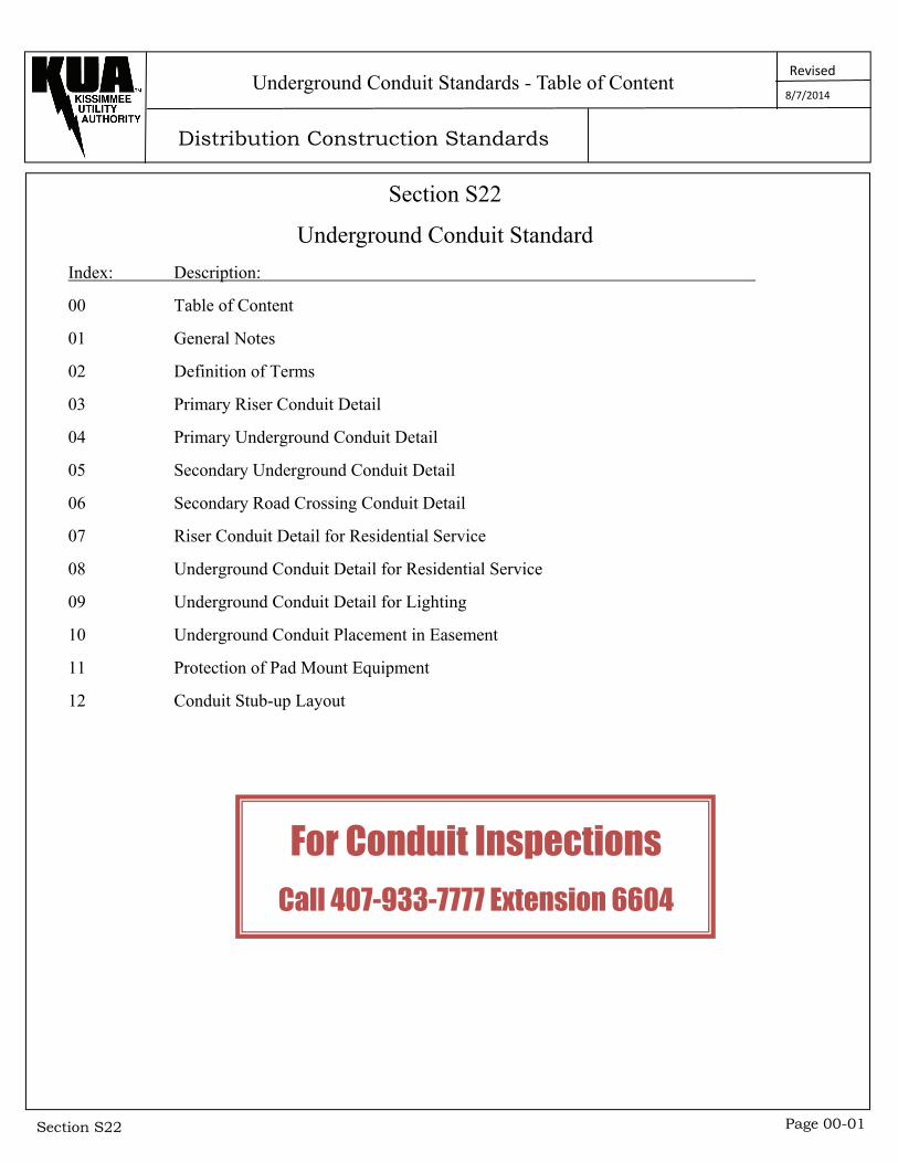
Section S22 Page 00-01
Section S22
Underground Conduit Standard
Index: Description:
00 Table of Content
01 General Notes
02 Definition of Terms
03 Primary Riser Conduit Detail
04 Primary Underground Conduit Detail
05 Secondary Underground Conduit Detail
06 Secondary Road Crossing Conduit Detail
07 Riser Conduit Detail for Residential Service
08 Underground Conduit Detail for Residential Service
09 Underground Conduit Detail for Lighting
10 Underground Conduit Placement in Easement
11 Protection of Pad Mount Equipment
12 Conduit Stub-up Layout
Underground Conduit Standards - Table of Content 8/7/2014
For Conduit Inspections
Call 407-933-7777 Extension 6604
Distribution Construction Standards
Revised
Section S22 Page 01-01
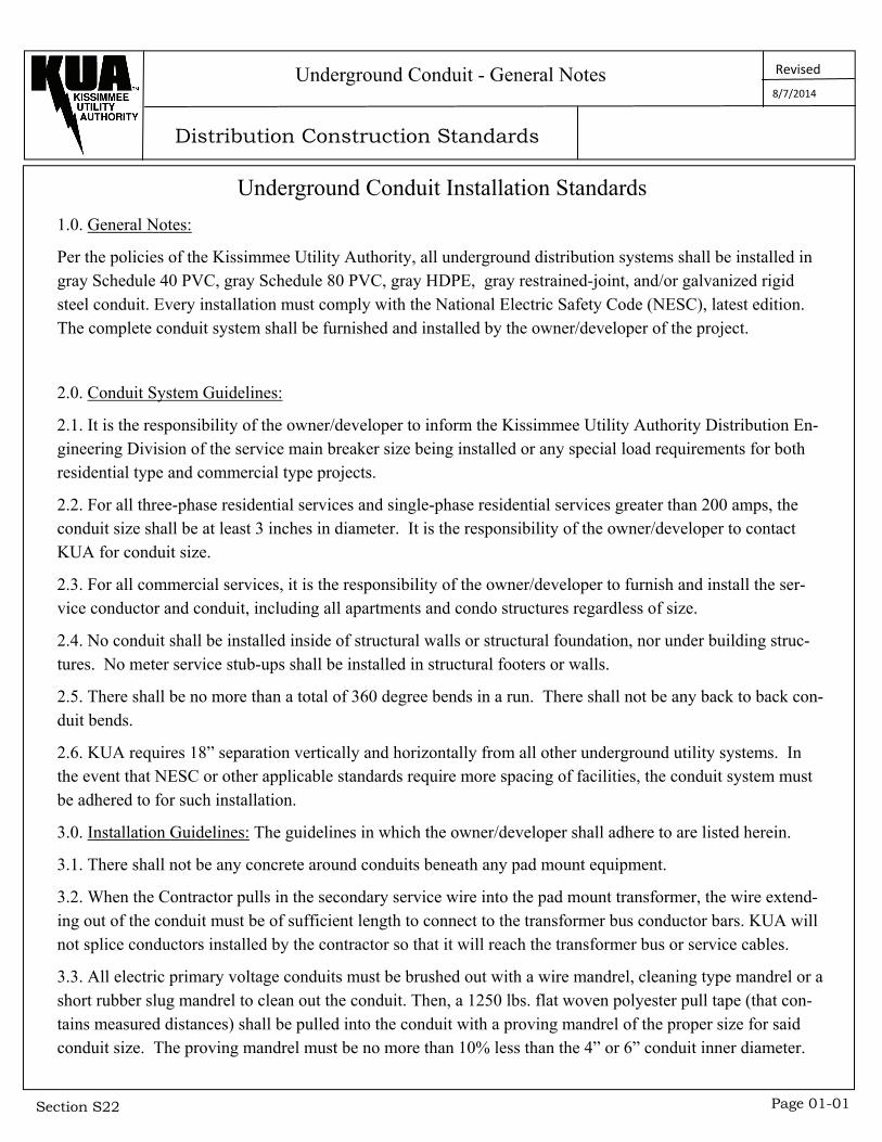
Underground Conduit Installation Standards
1.0. General Notes:
Per the policies of the Kissimmee Utility Authority, all underground distribution systems shall be installed in gray Schedule 40 PVC, gray Schedule 80 PVC, gray HDPE, gray restrained-joint, and/or galvanized rigid steel conduit. Every installation must comply with the National Electric Safety Code (NESC), latest edition. The complete conduit system shall be furnished and installed by the owner/developer of the project.
2.0. Conduit System Guidelines:
2.1. It is the responsibility of the owner/developer to inform the Kissimmee Utility Authority Distribution En-gineering Division of the service main breaker size being installed or any special load requirements for both residential type and commercial type projects.
2.2. For all three-phase residential services and single-phase residential services greater than 200 amps, the conduit size shall be at least 3 inches in diameter. It is the responsibility of the owner/developer to contact KUA for conduit size.
2.3. For all commercial services, it is the responsibility of the owner/developer to furnish and install the ser-vice conductor and conduit, including all apartments and condo structures regardless of size.
2.4. No conduit shall be installed inside of structural walls or structural foundation, nor under building struc-tures. No meter service stub-ups shall be installed in structural footers or walls.
2.5. There shall be no more than a total of 360 degree bends in a run. There shall not be any back to back con-duit bends.
2.6. KUA requires 18” separation vertically and horizontally from all other underground utility systems. In the event that NESC or other applicable standards require more spacing of facilities, the conduit system must be adhered to for such installation.
3.0. Installation Guidelines: The guidelines in which the owner/developer shall adhere to are listed herein.
3.1. There shall not be any concrete around conduits beneath any pad mount equipment.
3.2. When the Contractor pulls in the secondary service wire into the pad mount transformer, the wire extend-ing out of the conduit must be of sufficient length to connect to the transformer bus conductor bars. KUA will not splice conductors installed by the contractor so that it will reach the transformer bus or service cables.
3.3. All electric primary voltage conduits must be brushed out with a wire mandrel, cleaning type mandrel or a short rubber slug mandrel to clean out the conduit. Then, a 1250 lbs. flat woven polyester pull tape (that con-tains measured distances) shall be pulled into the conduit with a proving mandrel of the proper size for said conduit size. The proving mandrel must be no more than 10% less than the 4” or 6” conduit inner diameter.
Underground Conduit - General Notes 8/7/2014
Distribution Construction Standards
Revised
Section S22 Page 01-02
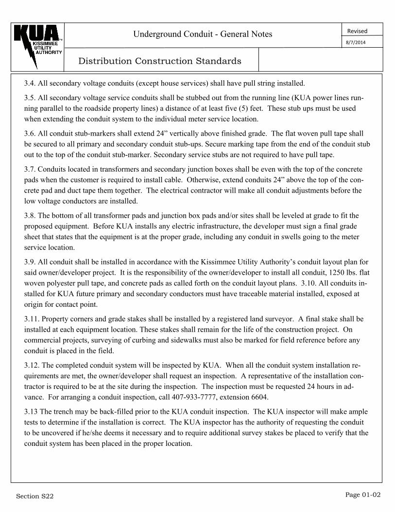
3.4. All secondary voltage conduits (except house services) shall have pull string installed.
3.5. All secondary voltage service conduits shall be stubbed out from the running line (KUA power lines run-ning parallel to the roadside property lines) a distance of at least five (5) feet. These stub ups must be used when extending the conduit system to the individual meter service location.
3.6. All conduit stub-markers shall extend 24” vertically above finished grade. The flat woven pull tape shall be secured to all primary and secondary conduit stub-ups. Secure marking tape from the end of the conduit stub out to the top of the conduit stub-marker. Secondary service stubs are not required to have pull tape.
3.7. Conduits located in transformers and secondary junction boxes shall be even with the top of the concrete pads when the customer is required to install cable. Otherwise, extend conduits 24” above the top of the con-crete pad and duct tape them together. The electrical contractor will make all conduit adjustments before the low voltage conductors are installed.
3.8. The bottom of all transformer pads and junction box pads and/or sites shall be leveled at grade to fit the proposed equipment. Before KUA installs any electric infrastructure, the developer must sign a final grade sheet that states that the equipment is at the proper grade, including any conduit in swells going to the meter service location.
3.9. All conduit shall be installed in accordance with the Kissimmee Utility Authority’s conduit layout plan for said owner/developer project. It is the responsibility of the owner/developer to install all conduit, 1250 lbs. flat woven polyester pull tape, and concrete pads as called forth on the conduit layout plans. 3.10. All conduits in-stalled for KUA future primary and secondary conductors must have traceable material installed, exposed at origin for contact point.
3.11. Property corners and grade stakes shall be installed by a registered land surveyor. A final stake shall be installed at each equipment location. These stakes shall remain for the life of the construction project. On commercial projects, surveying of curbing and sidewalks must also be marked for field reference before any conduit is placed in the field.
3.12. The completed conduit system will be inspected by KUA. When all the conduit system installation re-quirements are met, the owner/developer shall request an inspection. A representative of the installation con-tractor is required to be at the site during the inspection. The inspection must be requested 24 hours in ad-vance. For arranging a conduit inspection, call 407-933-7777, extension 6604.
3.13 The trench may be back-filled prior to the KUA conduit inspection. The KUA inspector will make ample tests to determine if the installation is correct. The KUA inspector has the authority of requesting the conduit to be uncovered if he/she deems it necessary and to require additional survey stakes be placed to verify that the conduit system has been placed in the proper location.
Underground Conduit - General Notes 8/7/2014
Distribution Construction Standards
Revised
Section S22 Page 01-03
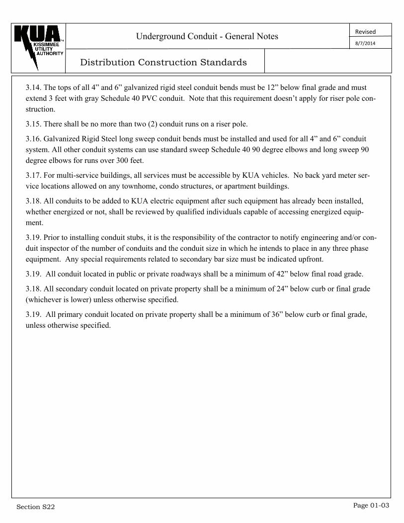
3.14. The tops of all 4” and 6” galvanized rigid steel conduit bends must be 12” below final grade and must extend 3 feet with gray Schedule 40 PVC conduit. Note that this requirement doesn’t apply for riser pole con-struction.
3.15. There shall be no more than two (2) conduit runs on a riser pole.
3.16. Galvanized Rigid Steel long sweep conduit bends must be installed and used for all 4” and 6” conduit system. All other conduit systems can use standard sweep Schedule 40 90 degree elbows and long sweep 90 degree elbows for runs over 300 feet.
3.17. For multi-service buildings, all services must be accessible by KUA vehicles. No back yard meter ser-vice locations allowed on any townhome, condo structures, or apartment buildings.
3.18. All conduits to be added to KUA electric equipment after such equipment has already been installed, whether energized or not, shall be reviewed by qualified individuals capable of accessing energized equip-ment.
3.19. Prior to installing conduit stubs, it is the responsibility of the contractor to notify engineering and/or con-duit inspector of the number of conduits and the conduit size in which he intends to place in any three phase equipment. Any special requirements related to secondary bar size must be indicated upfront.
3.19. All conduit located in public or private roadways shall be a minimum of 42” below final road grade.
3.18. All secondary conduit located on private property shall be a minimum of 24” below curb or final grade (whichever is lower) unless otherwise specified.
3.19. All primary conduit located on private property shall be a minimum of 36” below curb or final grade, unless otherwise specified.
Underground Conduit - General Notes 8/7/2014
Distribution Construction Standards
Revised
Section S22 Page 02-01
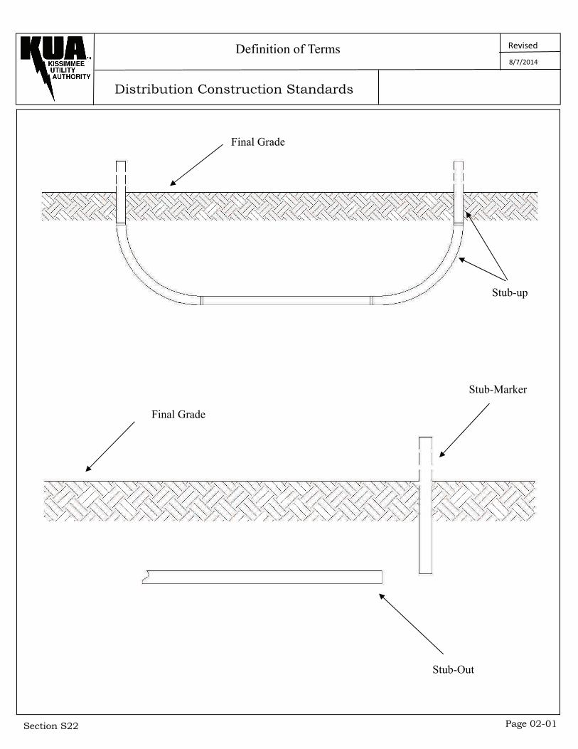
Definition of Terms
Final Grade
Stub-up
Final Grade
Stub-Marker
Stub-Out
8/7/2014
Distribution Construction Standards
Revised
Section S22 Page 03-01
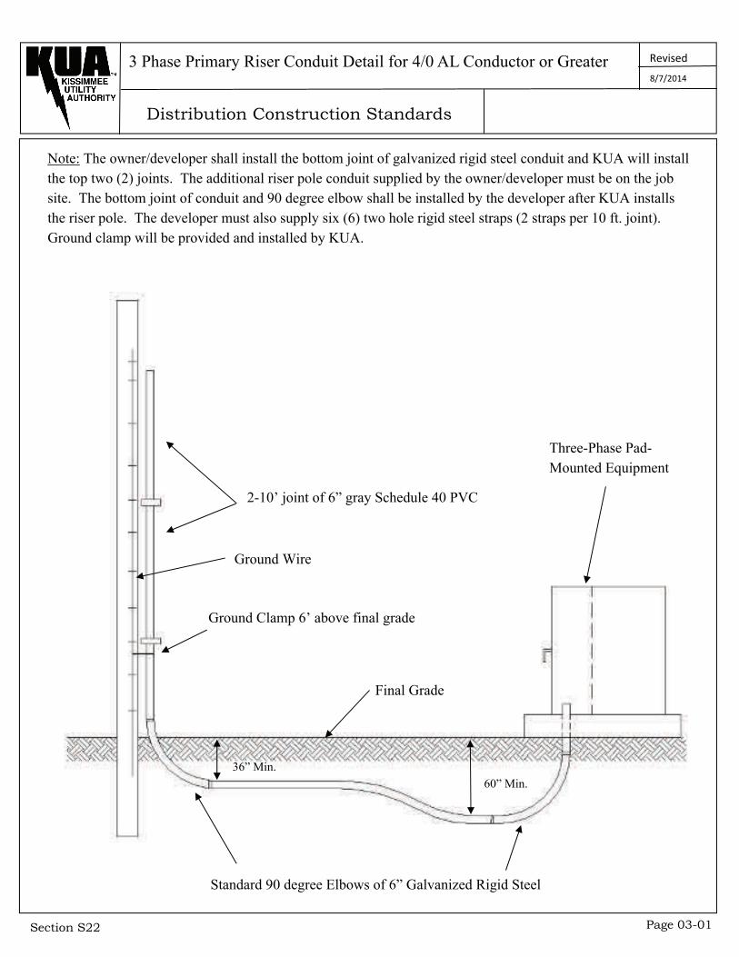
3 Phase Primary Riser Conduit Detail for 4/0 AL Conductor or Greater
Note: The owner/developer shall install the bottom joint of galvanized rigid steel conduit and KUA will install the top two (2) joints. The additional riser pole conduit supplied by the owner/developer must be on the job site. The bottom joint of conduit and 90 degree elbow shall be installed by the developer after KUA installs the riser pole. The developer must also supply six (6) two hole rigid steel straps (2 straps per 10 ft. joint). Ground clamp will be provided and installed by KUA.
2-10’ joint of 6” gray Schedule 40 PVC
Ground Wire
Final Grade
36” Min.
Ground Clamp 6’ above final grade
60” Min.
Three-Phase Pad-Mounted Equipment
Standard 90 degree Elbows of 6” Galvanized Rigid Steel
8/7/2014
Distribution Construction Standards
Revised
Section S22 Page 03-02
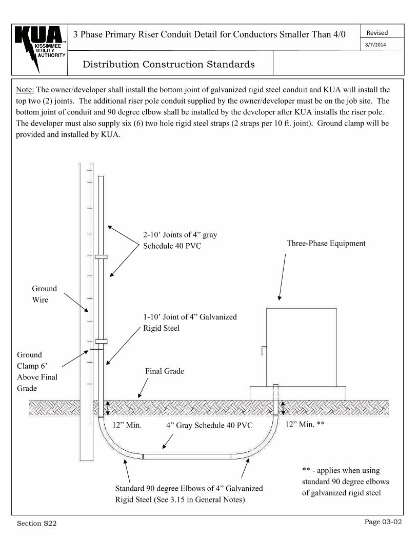
Note: The owner/developer shall install the bottom joint of galvanized rigid steel conduit and KUA will install the top two (2) joints. The additional riser pole conduit supplied by the owner/developer must be on the job site. The bottom joint of conduit and 90 degree elbow shall be installed by the developer after KUA installs the riser pole. The developer must also supply six (6) two hole rigid steel straps (2 straps per 10 ft. joint). Ground clamp will be provided and installed by KUA.
3 Phase Primary Riser Conduit Detail for Conductors Smaller Than 4/0
2-10’ Joints of 4” gray Schedule 40 PVC
Ground Wire
Ground Clamp 6’ Above Final Grade
1-10’ Joint of 4” Galvanized Rigid Steel
Final Grade
Three-Phase Equipment
12” Min. 4” Gray Schedule 40 PVC
Standard 90 degree Elbows of 4” Galvanized Rigid Steel (See 3.15 in General Notes)
** - applies when using standard 90 degree elbows of galvanized rigid steel
12” Min. **
8/7/2014
Distribution Construction Standards
Revised
Section S22 Page 03-03
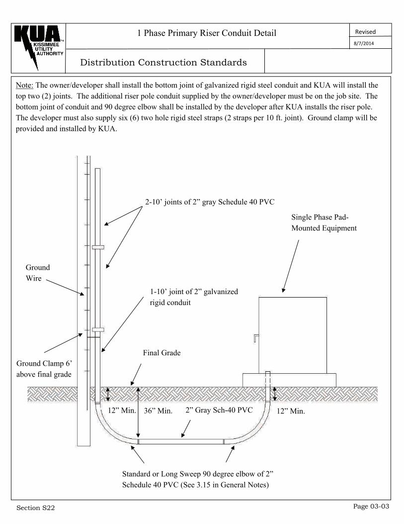
1 Phase Primary Riser Conduit Detail
Note: The owner/developer shall install the bottom joint of galvanized rigid steel conduit and KUA will install the top two (2) joints. The additional riser pole conduit supplied by the owner/developer must be on the job site. The bottom joint of conduit and 90 degree elbow shall be installed by the developer after KUA installs the riser pole. The developer must also supply six (6) two hole rigid steel straps (2 straps per 10 ft. joint). Ground clamp will be provided and installed by KUA.
2-10’ joints of 2” gray Schedule 40 PVC
Ground Wire
Ground Clamp 6’ above final grade
1-10’ joint of 2” galvanized rigid conduit
Single Phase Pad-Mounted Equipment
Final Grade
36” Min. 12” Min. 2” Gray Sch-40 PVC 12” Min.
Standard or Long Sweep 90 degree elbow of 2” Schedule 40 PVC (See 3.15 in General Notes)
8/7/2014
Distribution Construction Standards
Revised
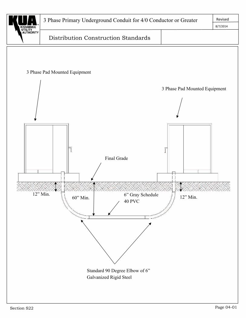
Section S22 Page 04-01
3 Phase Primary Underground Conduit for 4/0 Conductor or Greater
12” Min.
3 Phase Pad Mounted Equipment
6” Gray Schedule 40 PVC
Final Grade
Standard 90 Degree Elbow of 6” Galvanized Rigid Steel
3 Phase Pad Mounted Equipment
60” Min. 12” Min.
8/7/2014
Distribution Construction Standards
Revised
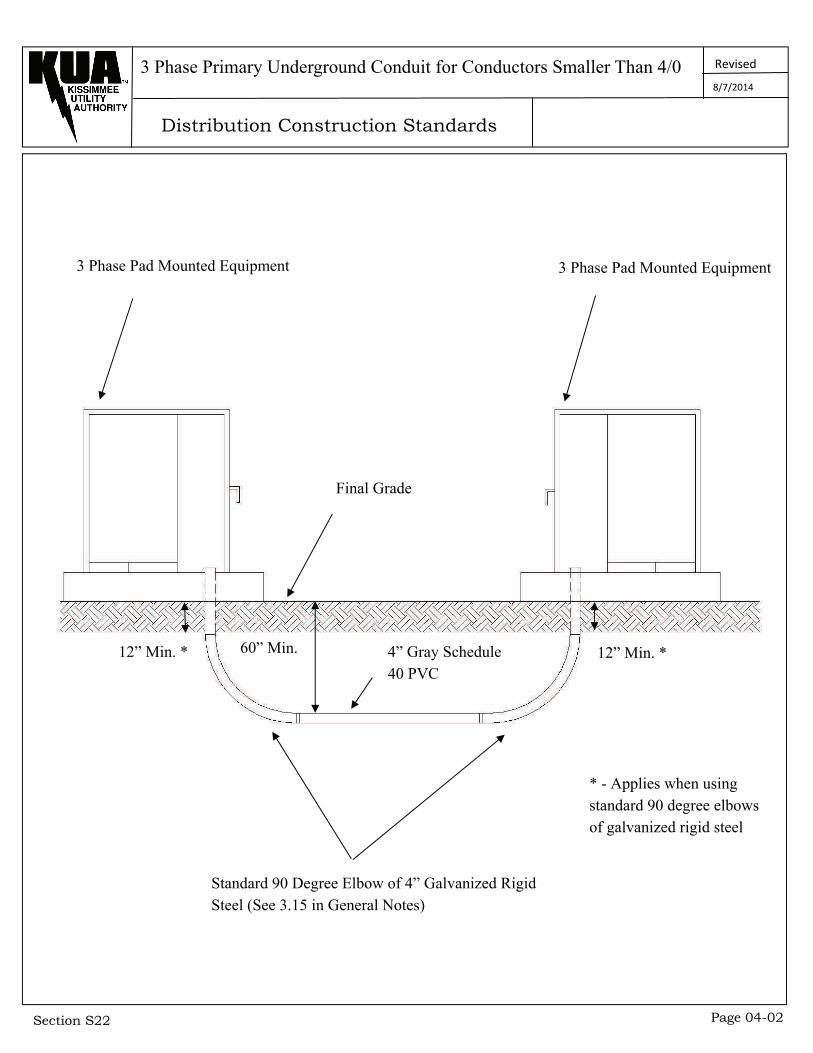
Section S22 Page 04-02
3 Phase Primary Underground Conduit for Conductors Smaller Than 4/0
3 Phase Pad Mounted Equipment 3 Phase Pad Mounted Equipment
12” Min. *
Final Grade
60” Min. 4” Gray Schedule 40 PVC
12” Min. *
Standard 90 Degree Elbow of 4” Galvanized Rigid Steel (See 3.15 in General Notes)
* - Applies when using standard 90 degree elbows of galvanized rigid steel
8/7/2014
Distribution Construction Standards
Revised
Section S22 Page 04-03
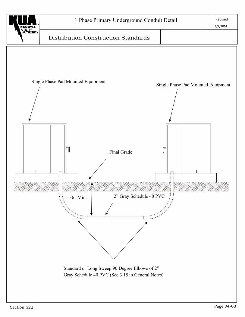
Single Phase Pad Mounted Equipment
1 Phase Primary Underground Conduit Detail
Single Phase Pad Mounted Equipment
Final Grade
36” Min. 2” Gray Schedule 40 PVC
Standard or Long Sweep 90 Degree Elbows of 2” Gray Schedule 40 PVC (See 3.15 in General Notes)
8/7/2014
Distribution Construction Standards
Revised
Section S22 Page 05-01
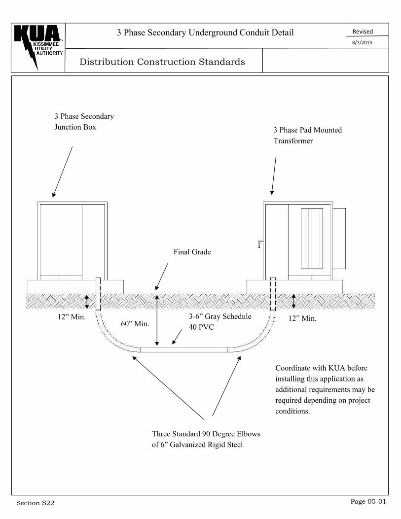
3 Phase Secondary Underground Conduit Detail
3 Phase Secondary Junction Box 3 Phase Pad Mounted
Transformer
Final Grade
60” Min. 3-6” Gray Schedule 40 PVC
12” Min. 12” Min.
Coordinate with KUA before installing this application as additional requirements may be required depending on project conditions.
Three Standard 90 Degree Elbows of 6” Galvanized Rigid Steel
8/7/2014
Distribution Construction Standards
Revised
Section S22 Page 05-02
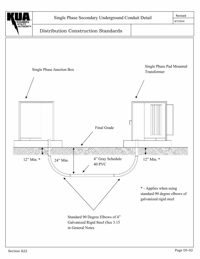
Single Phase Junction Box Single Phase Pad Mounted Transformer
Single Phase Secondary Underground Conduit Detail
Final Grade
12” Min. * 12” Min. * 24” Min. 4” Gray Schedule 40 PVC
Standard 90 Degree Elbows of 4” Galvanized Rigid Steel (See 3.15 in General Notes
* - Applies when using standard 90 degree elbows of galvanized rigid steel
8/7/2014
Distribution Construction Standards
Revised
Section S22 Page 06-01
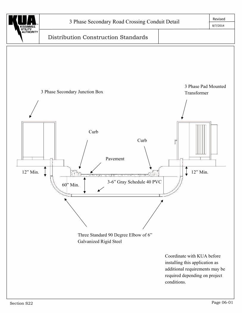
3 Phase Secondary Road Crossing Conduit Detail
3 Phase Secondary Junction Box 3 Phase Pad Mounted Transformer
12” Min. 12” Min.
Curb
Pavement
Curb
60” Min. 3-6” Gray Schedule 40 PVC
Three Standard 90 Degree Elbow of 6” Galvanized Rigid Steel
Coordinate with KUA before installing this application as additional requirements may be required depending on project conditions.
8/7/2014
Distribution Construction Standards
Revised
Section S22 Page 06-02
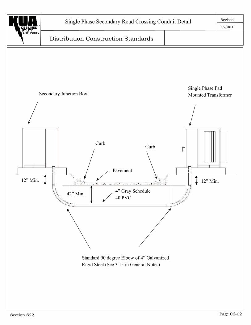
Single Phase Secondary Road Crossing Conduit Detail
Secondary Junction Box Single Phase Pad Mounted Transformer
Curb
Pavement
Curb
12” Min. 12” Min.
42” Min.
Standard 90 degree Elbow of 4” Galvanized Rigid Steel (See 3.15 in General Notes)
4” Gray Schedule 40 PVC
8/7/2014
Distribution Construction Standards
Revised
Section S22 Page 07-01
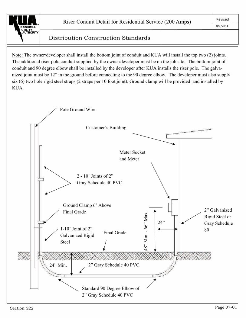
Note: The owner/developer shall install the bottom joint of conduit and KUA will install the top two (2) joints. The additional riser pole conduit supplied by the owner/developer must be on the job site. The bottom joint of conduit and 90 degree elbow shall be installed by the developer after KUA installs the riser pole. The galva-nized joint must be 12” in the ground before connecting to the 90 degree elbow. The developer must also supply six (6) two hole rigid steel straps (2 straps per 10 foot joint). Ground clamp will be provided and installed by KUA.
Riser Conduit Detail for Residential Service (200 Amps)
Pole Ground Wire
2 - 10’ Joints of 2” Gray Schedule 40 PVC
Ground Clamp 6’ Above Final Grade
1-10’ Joint of 2” Galvanized Rigid Steel
24”
48”
Min
. - 6
6” M
ax.
Meter Socket and Meter
Customer’s Building
2” Galvanized Rigid Steel or Gray Schedule 80
Final Grade
24” Min. 2” Gray Schedule 40 PVC
Standard 90 Degree Elbow of 2” Gray Schedule 40 PVC
8/7/2014

Distribution Construction Standards
Revised
Section S22 Page 07-02
Note: The owner/developer shall install the bottom joint of conduit and KUA will install the top two (2) joints. The additional riser pole conduit supplied by the owner/developer must be on the job site. The bottom joint of conduit and 90 degree elbow shall be installed by the developer after KUA installs the riser pole. The galva-nized joint must be 12” in the ground before connecting to the 90 degree elbow. The developer must also supply six (6) two hole rigid steel straps (2 straps per 10 foot joint). Ground clamp will be provided and installed by KUA.
Riser Conduit Detail for Residential Service (Greater Than 200 Amps)
Pole Ground Wire
2 - 10’ Joints of 3” Gray Schedule 40 PVC
Ground Clamp 6’ Above Final Grade
1-10’ Joint of 3” Galvanized Rigid Steel
24”
48”
Min
. - 6
6” M
ax.
Meter Socket and Meter
Customer’s Building
3” Galvanized Rigid Steel or Gray Schedule 80
Final Grade
24” Min. 3” Gray Schedule 40 PVC
Standard 90 Degree Elbow of 2” Gray Schedule 40 PVC
8/7/2014
Distribution Construction Standards
Revised
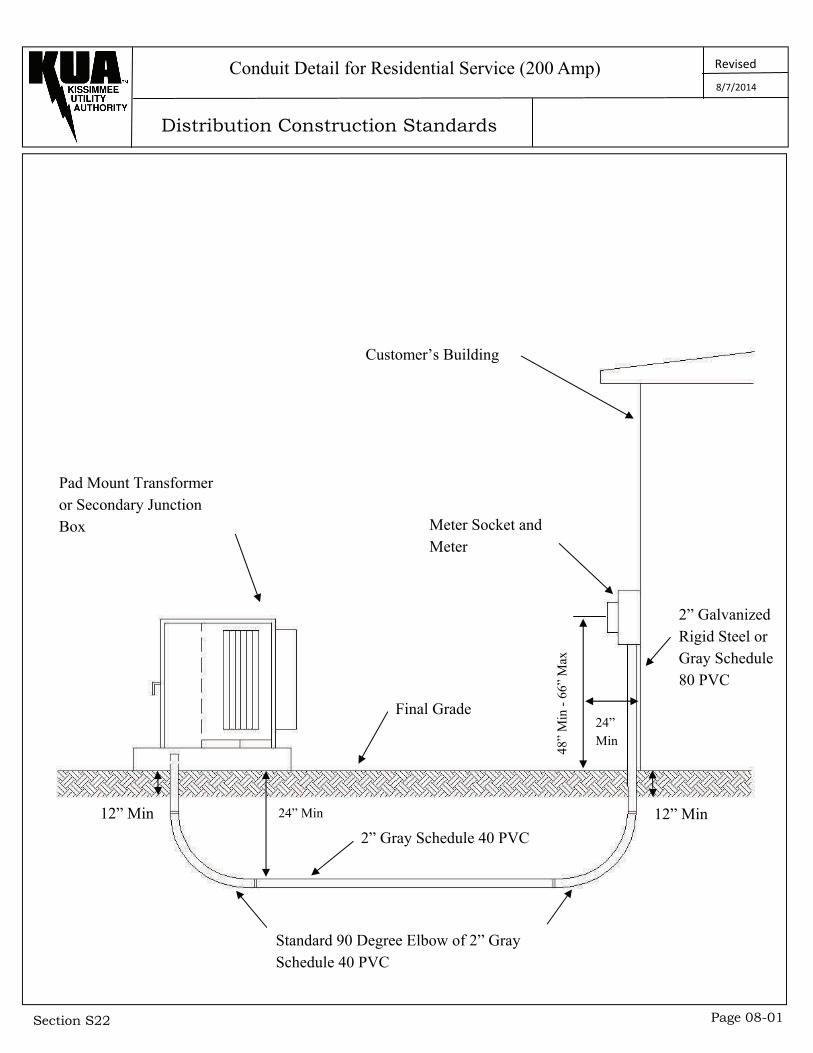
Section S22 Page 08-01
Conduit Detail for Residential Service (200 Amp)
Pad Mount Transformer or Secondary Junction Box
Customer’s Building
12” Min 12” Min
48”
Min
- 6
6” M
ax
24” Min
Final Grade
2” Galvanized Rigid Steel or Gray Schedule 80 PVC
Meter Socket and Meter
24” Min
2” Gray Schedule 40 PVC
Standard 90 Degree Elbow of 2” Gray Schedule 40 PVC
8/7/2014
Distribution Construction Standards
Revised
Section S22 Page 08-01
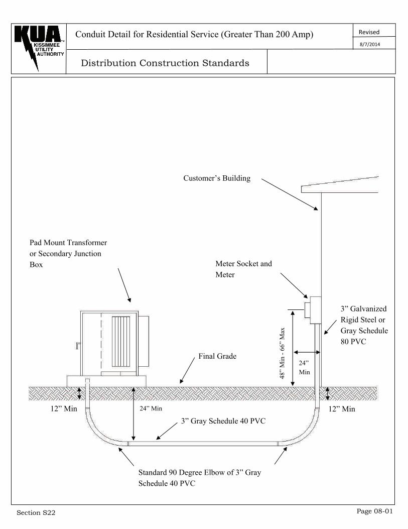
Conduit Detail for Residential Service (Greater Than 200 Amp)
Pad Mount Transformer or Secondary Junction Box
Customer’s Building
12” Min 12” Min
48”
Min
- 6
6” M
ax
24” Min
Final Grade
3” Galvanized Rigid Steel or Gray Schedule 80 PVC
Meter Socket and Meter
24” Min
3” Gray Schedule 40 PVC
Standard 90 Degree Elbow of 3” Gray Schedule 40 PVC
8/7/2014
Distribution Construction Standards
Revised
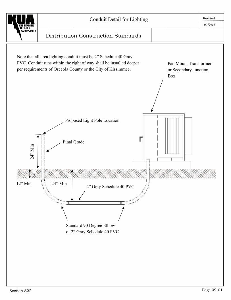
Section S22 Page 09-01
Conduit Detail for Lighting
Pad Mount Transformer or Secondary Junction Box
12” Min
24”
Min
Proposed Light Pole Location
Final Grade
24” Min 2” Gray Schedule 40 PVC
Note that all area lighting conduit must be 2” Schedule 40 Gray PVC. Conduit runs within the right of way shall be installed deeper per requirements of Osceola County or the City of Kissimmee.
Standard 90 Degree Elbow of 2” Gray Schedule 40 PVC
8/7/2014
Distribution Construction Standards
Revised
Section S22 Page 10-01
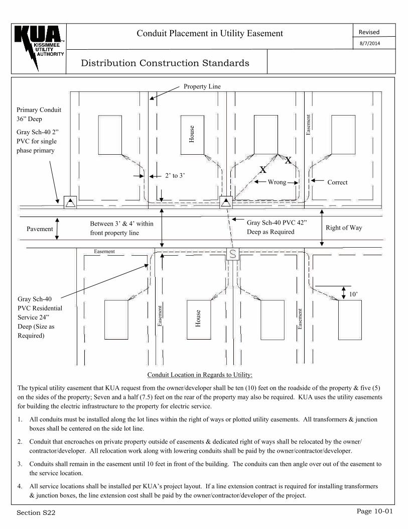
Conduit Placement in Utility Easement
Primary Conduit 36” Deep
Gray Sch-40 2” PVC for single phase primary
Property Line
2’ to 3’
Hou
se
X X
Wrong
Pavement
Easement
Correct
Eas
emen
t
Between 3’ & 4’ within front property line
Eas
emen
t
Gray Sch-40 PVC 42” Deep as Required
Right of Way
10’ E
asem
ent
Hou
se
Gray Sch-40 PVC Residential Service 24” Deep (Size as Required)
Conduit Location in Regards to Utility:
The typical utility easement that KUA request from the owner/developer shall be ten (10) feet on the roadside of the property & five (5) on the sides of the property; Seven and a half (7.5) feet on the rear of the property may also be required. KUA uses the utility easements for building the electric infrastructure to the property for electric service.
1. All conduits must be installed along the lot lines within the right of ways or plotted utility easements. All transformers & junction boxes shall be centered on the side lot line.
2. Conduit that encroaches on private property outside of easements & dedicated right of ways shall be relocated by the owner/contractor/developer. All relocation work along with lowering conduits shall be paid by the owner/contractor/developer.
3. Conduits shall remain in the easement until 10 feet in front of the building. The conduits can then angle over out of the easement to the service location.
4. All service locations shall be installed per KUA’s project layout. If a line extension contract is required for installing transformers & junction boxes, the line extension cost shall be paid by the owner/contractor/developer of the project.
8/7/2014
Distribution Construction Standards
Revised
Section S22 Page 11-01
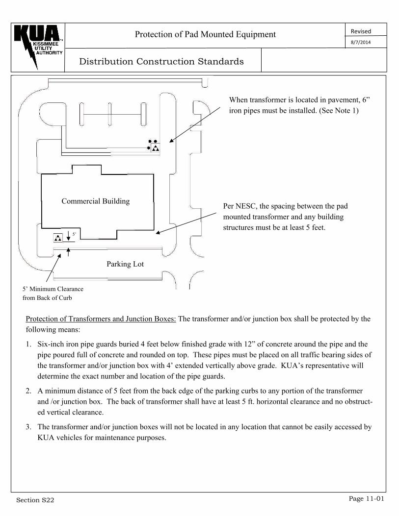
Protection of Pad Mounted Equipment
Commercial Building
5’
Parking Lot
5’ Minimum Clearance from Back of Curb
When transformer is located in pavement, 6” iron pipes must be installed. (See Note 1)
Per NESC, the spacing between the pad mounted transformer and any building structures must be at least 5 feet.
Protection of Transformers and Junction Boxes: The transformer and/or junction box shall be protected by the following means:
1. Six-inch iron pipe guards buried 4 feet below finished grade with 12” of concrete around the pipe and the pipe poured full of concrete and rounded on top. These pipes must be placed on all traffic bearing sides of the transformer and/or junction box with 4’ extended vertically above grade. KUA’s representative will determine the exact number and location of the pipe guards.
2. A minimum distance of 5 feet from the back edge of the parking curbs to any portion of the transformer and /or junction box. The back of transformer shall have at least 5 ft. horizontal clearance and no obstruct-ed vertical clearance.
3. The transformer and/or junction boxes will not be located in any location that cannot be easily accessed by KUA vehicles for maintenance purposes.
8/7/2014
Distribution Construction Standards
Revised
Section S22 Page 12-01
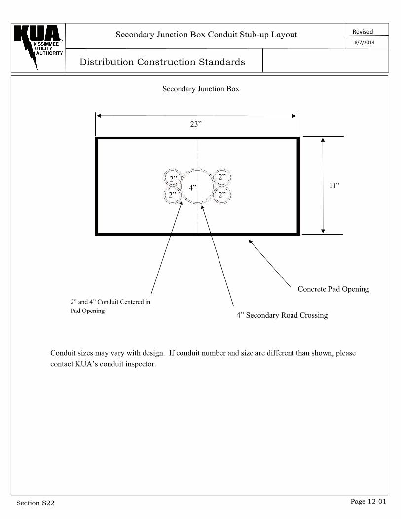
Secondary Junction Box Conduit Stub-up Layout
Secondary Junction Box
23”
4” 2”
2” 2”
2” 11”
Concrete Pad Opening
4” Secondary Road Crossing
2” and 4” Conduit Centered in Pad Opening
Conduit sizes may vary with design. If conduit number and size are different than shown, please contact KUA’s conduit inspector.
8/7/2014
Distribution Construction Standards
Revised
Section S22 Page 12-02
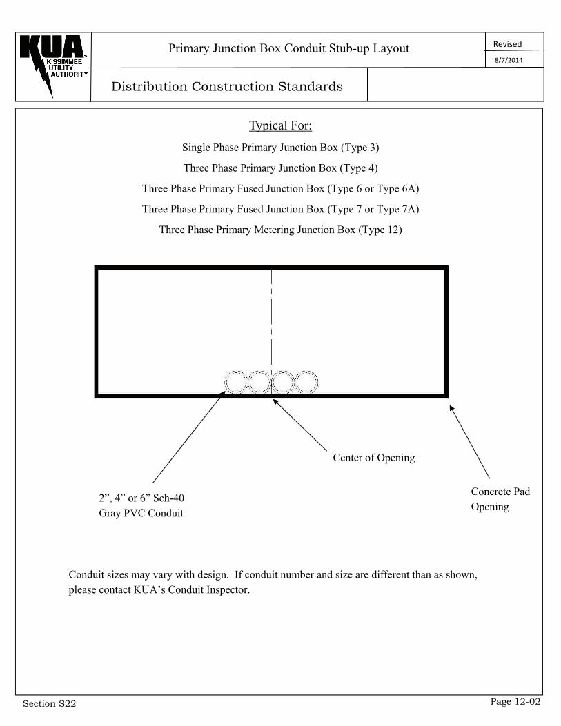
Primary Junction Box Conduit Stub-up Layout
Typical For:
Single Phase Primary Junction Box (Type 3)
Three Phase Primary Junction Box (Type 4)
Three Phase Primary Fused Junction Box (Type 6 or Type 6A)
Three Phase Primary Fused Junction Box (Type 7 or Type 7A)
Three Phase Primary Metering Junction Box (Type 12)
Center of Opening
Concrete Pad Opening
2”, 4” or 6” Sch-40 Gray PVC Conduit
Conduit sizes may vary with design. If conduit number and size are different than as shown, please contact KUA’s Conduit Inspector.
8/7/2014
Distribution Construction Standards
Revised
Section S22 Page 12-03
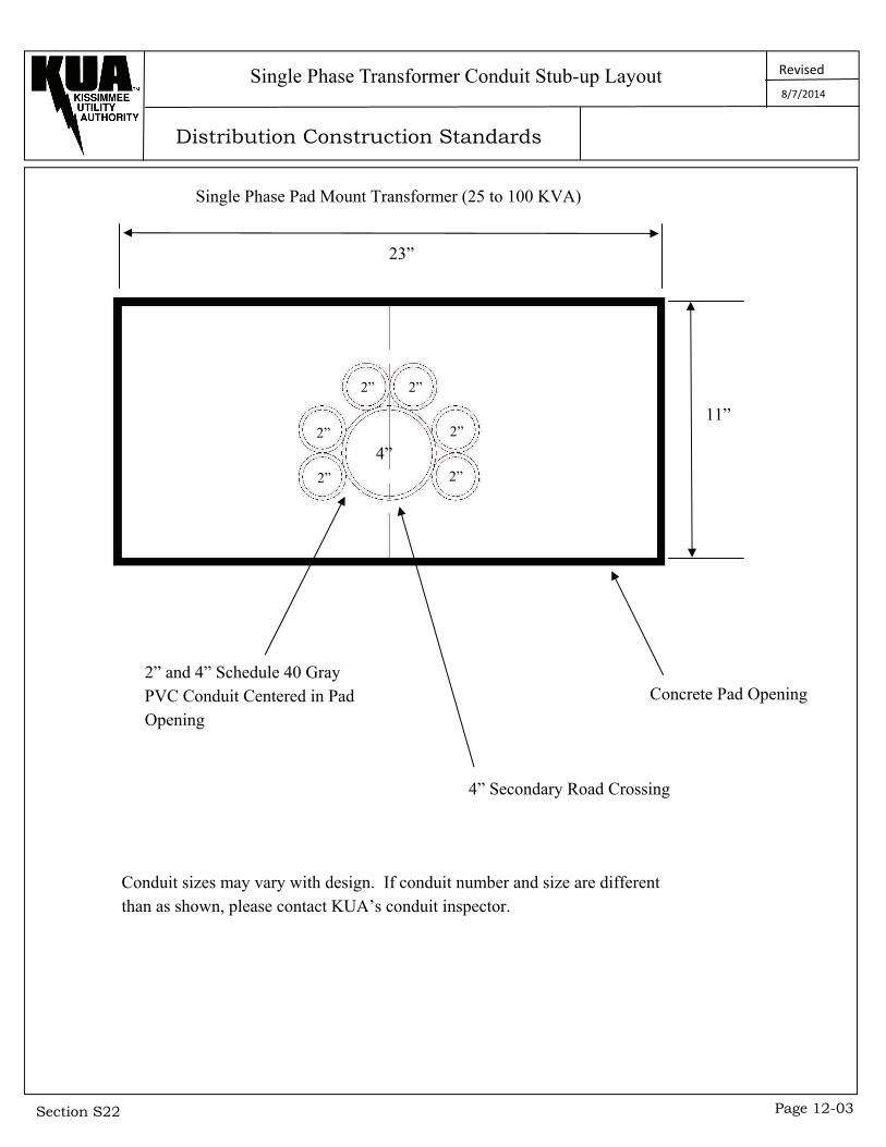
Single Phase Transformer Conduit Stub-up Layout
4” 2”
2”
2” 2”
2”
2”
23”
11”
Concrete Pad Opening
4” Secondary Road Crossing
2” and 4” Schedule 40 Gray PVC Conduit Centered in Pad Opening
Conduit sizes may vary with design. If conduit number and size are different than as shown, please contact KUA’s conduit inspector.
Single Phase Pad Mount Transformer (25 to 100 KVA)
8/7/2014
Distribution Construction Standards
Revised
Section S22 Page 12-04
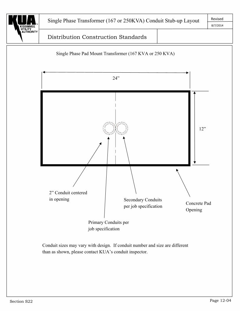
Single Phase Transformer (167 or 250KVA) Conduit Stub-up Layout
Single Phase Pad Mount Transformer (167 KVA or 250 KVA)
24”
12”
Concrete Pad Opening
Secondary Conduits per job specification
Primary Conduits per job specification
2” Conduit centered in opening
Conduit sizes may vary with design. If conduit number and size are different than as shown, please contact KUA’s conduit inspector.
8/7/2014

Distribution Construction Standards
Revised
Section S22 Page 12-05
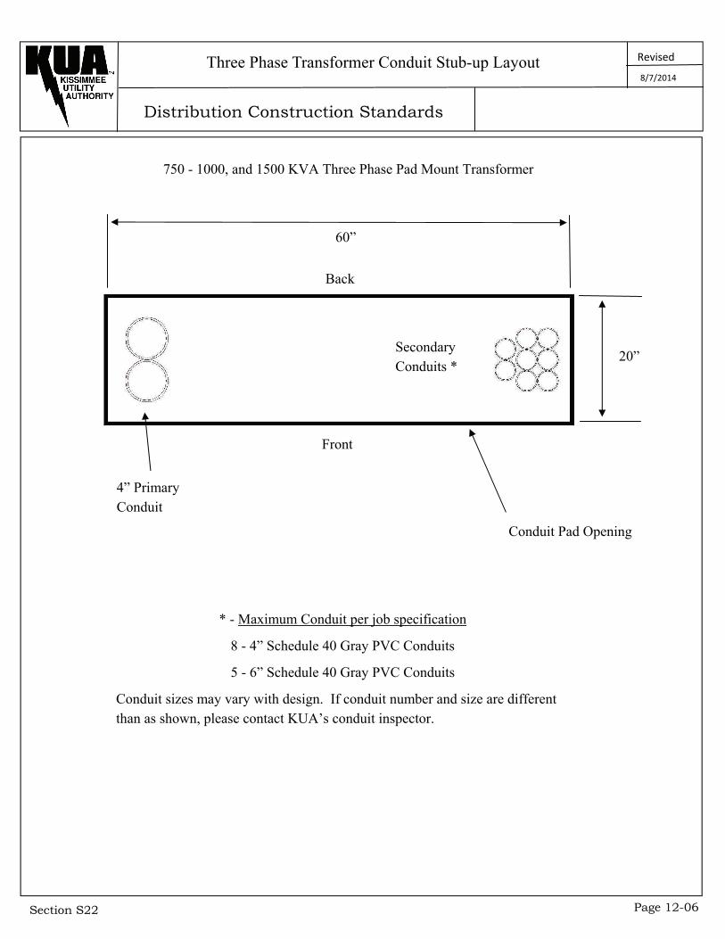
Three Phase Transformer Conduit Stub-up Layout
75 - 112 - 150 - 225 - 300 - 500 KVA Three Phase Pad Mount Transformer
44”
Back
Front
Secondary Conduits *
Conduit Pad Opening
4” Primary Conduit
* - Maximum Conduit per job specification
8 - 4” Schedule 40 Gray PVC Conduits
5 - 6” Schedule 40 Gray PVC Conduits
Conduit sizes may vary with design. If conduit number and size are different than as shown, please contact KUA’s conduit inspector.
8/7/2014
12”
Distribution Construction Standards
Revised
Section S22 Page 12-06
Three Phase Transformer Conduit Stub-up Layout
750 - 1000, and 1500 KVA Three Phase Pad Mount Transformer
60”
Back
Front
Secondary Conduits *
Conduit Pad Opening
4” Primary Conduit
* - Maximum Conduit per job specification
8 - 4” Schedule 40 Gray PVC Conduits
5 - 6” Schedule 40 Gray PVC Conduits
Conduit sizes may vary with design. If conduit number and size are different than as shown, please contact KUA’s conduit inspector.
8/7/2014
20”

Distribution Construction Standards
Revised
Section S22 Page 12-07
Three Phase Transformer Conduit Stub-up Layout
2000 KVA Three Phase Pad Mount Transformer
68”
Back
Front
Secondary Conduits *
Conduit Pad Opening
4” Primary Conduit
* - Maximum Conduit per job specification
8 - 4” Schedule 40 Gray PVC Conduits
6 - 6” Schedule 40 Gray PVC Conduits
Conduit sizes may vary with design. If conduit number and size are different than as shown, please contact KUA’s conduit inspector.
8/7/2014
18”
Distribution Construction Standards
Revised
Section S22 Page 12-08
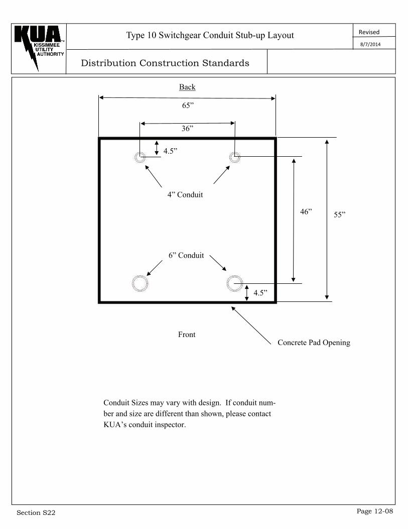
Type 10 Switchgear Conduit Stub-up Layout 8/7/2014
4.5”
46”
36”
Back
55”
4.5”
4” Conduit
6” Conduit
Concrete Pad Opening Front
Conduit Sizes may vary with design. If conduit num-ber and size are different than shown, please contact KUA’s conduit inspector.
65”

Distribution Construction Standards
Revised
Section S22 Page 12-09
Type 11 Switchgear Conduit Stub-up Layout 8/7/2014
36”
67”
Back
7.25”
7.25”
15.5” 48” 62.5”
15.5”
6” Conduit
6” Conduit
4” Conduit
6” Conduit
Front
Concrete Pad Opening
Conduit sizes may vary with design. If conduit number and size are different, please contact KUA’s conduit inspector.
Distribution Construction Standards
Revised
Section S22 Page 12-10
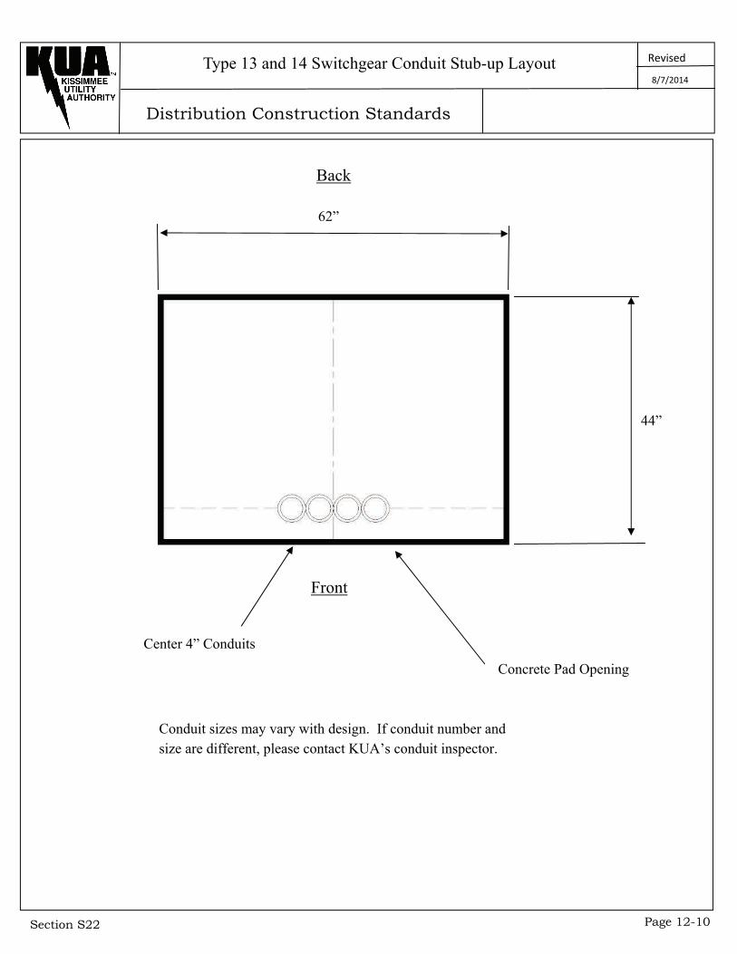
Type 13 and 14 Switchgear Conduit Stub-up Layout 8/7/2014
62”
Back
44”
Front
Conduit sizes may vary with design. If conduit number and size are different, please contact KUA’s conduit inspector.
Concrete Pad Opening
Center 4” Conduits
Distribution Construction Standards
Revised
Section S22 Page 12-11
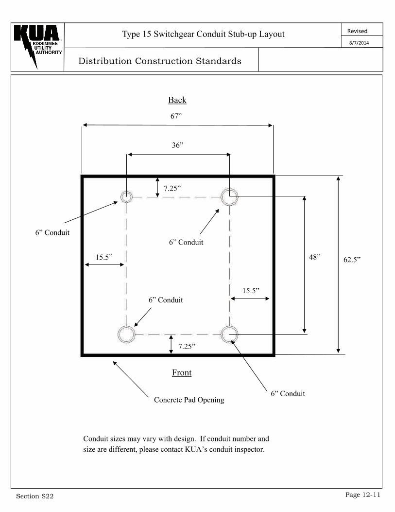
Type 15 Switchgear Conduit Stub-up Layout 8/7/2014
36”
67”
Back
7.25”
7.25”
15.5” 48” 62.5”
15.5”
6” Conduit
6” Conduit
6” Conduit
6” Conduit
Front
Concrete Pad Opening
Conduit sizes may vary with design. If conduit number and size are different, please contact KUA’s conduit inspector.
Distribution Construction Standards
Revised
Section S22 Page 12-12
Open Delta Conduit Stub-up Layout 8/7/2014
24” 24”
40”
2” Conduit High Leg
2” Conduit Primary
2” Conduit Centered in Opening
2” Conduit Bridge
Conduit Future Service
12” 12”
Concrete Pad Opening
2” Conduit High Leg
2” Conduit Primary
2” Conduit Bridge
Concrete Pad Opening