Embed Size (px)
Citation preview
AD/A-004 462
STORABILITY INVESTIGATIONS OF WATERLONG-TERM STORAGE EVALUATION
E. M. Vander Wall, et al IAerojet Liquid Rocket Company
Prc pared for: i
Air Force Rocket Propulsion Laboratory
December 1974
DISTRIBUTED BY:
Nationl Technical Information ServiceU. S. DEPARTMENT OF COMMERCE
UNCLASSIFIEDSECURITY CLASSIFICATION OF THIS PAGC (When Dotat Entered)
READ INSTRU'CTIONSREPORT DOCUMENTATION PAGE BEFORE COMPLETINS. I.ORMJt'-14PONT NUMBER - ----- . GOVT ACCESSION NO. 3. CPI T'CA LUNI IE
AFRPL-TR-74-76 a0Wgx4. TITLE (and Su~btite) S. TYPE OF REPORT & pEklo00 COVERED
Storability Investigations of Water, Long-Term ,Annual
Storage Evaluation 6. PERFORMING ORG. REPORT NUMBER
7. AU THOR(s) 0. CONTRACT OR GRANT NUMPEIR(.)
Vander Wall, E. M., and Janser, G. R. F04611-72-C-0062
9. PERFCO.JINO ORWGANIZATION NAME AND ADDRESS 10. PROGRAM ECFM NT. WF :T, TASK.AREA AWORK UNI P!,,fJ jRS
Aerojet Liquid Rocket Company 62302F, 3059, 11Sacramento, California
ICONTROLLING OFFICE NAME AND ADDRESS 12. REPORT DATE:
Air Force Rocket Propulsion Laboratory - 77em_ - l97413. N;UMAF A OFi PA C,.Edwards, California 93523&6
M.IONITORING AGENCY NAME &ADDRESS(if diIlaenI (romn Controlllod! OlIIce) IS. SECURITY CL AST (A ,f ...-.. tJ
Unclassified1947-. OCL ASS( I CA NO N '~n'ri Af )N
SCHEDULE
L. -6IsTRiii 6d66__TIO f~ SAEENT (;'t cth-I R port-)
Approved for Public Release; Distribution unlimited.
I? DSRIEUTION ST hTEMENT (of the obstroct entered in Block 20. it ?dffnI 1I,.,, R#po1f)
S-.-.-----.- P, 7 1975It. SUPI'LEMENTARY NOTES Itn,-do~ed by EHIA AL..I~~
INFORMATION SERVICE Ir U S r.t~er'o# of CommerceSprmgf od VA 22?1
1-KE'; WORDS (Cnl.eon -eras. 3ld. II necoe-ary and Identify by bf-tr number)
Hig Purity Water, Stainless Steels, Inconel, Titanium, Particulate-Formationin Water, Effect of Microorganisms on Water Storability, Fluid/MaterialCompatibility, Biological Growth, Long-Teri Storage of Water
20. A8STRAC ...rc ongo~.deI eetry end IdttnI$ty by 11., h S b
The objective of this program is to gather data that will permit the AirForce to assess the long term storage characteristics of water particularlywith regard to formation of particulate matter, so that the feasibility oflong-term storage of water for use as a transpiration coolant can be deter-mined. Five metallic materials of construction are included in the program:304 stainless steel, A-286 (aged) steel, 17-4 (aged) stainless steel,Inconel 718 (aged), 6A1-4V titanium (STA). Two types of water are used in
ODno 1473 EDITION OF I NOV 65 IS OBSOLETE ~UCASFE
SECURITY CLASSIFICATION OF THISPG ("otn Data rnte.Sd)
PRICES SUBJECT low CIIANG~r
UNCLASSIFIEDSECURITY CLASSIFICAIION OF THIS PAGE(WhW D*s1 Entered)
Abstract (cont.)
the program: oxygen-saturated, deionized, filtered, and oxygen-free,deionized, filtered. Five-year storage tests have been initiated in 304 and17-4 PH stainless steels, A-286 steel, Inconel 718, and 6AI-4V titanium (STA)containers using the filtered, deionized waters.
Evaluation of water and containers stored for six-months and twelve-monthshas been completed. The data show that both oxygen-saturated and oxygen-freewater can be stored in appropriate metal containers for the selected timeperiods without detrimental particulate matter formation or significantchanges in the quality of the water. It is in excellent cundition fortranspiration coolant purposes.
UNCLASSIFIED
SECURITY CLASSIFICATION OF THIS PAGE(Who Pots Entered)
NTIS IWi .'- . Gc: I
.I . i',! C~ r; ........ ................
When U.S. Government drawings, specifications, or other data areS. used for any purpose other than a definitely related Government
procurement operation, the Government thereby incurs no responsi-i bility nor any obligation whatsover, and the fact that the
Government may have formulated, furnished, or in any way suppliedthe said drawings, specifica'ions, or other data, is not to beregarded by implication or otherwise, or in any manner licensingthe holder or any other person or corporation, or conveying anyrights or permission to manufacture, use, or sell any patentedinvention that may in any way be related thereto.
FOREWORD
This report covers the work performed under Contract F04611-72-C-OOL2,
"Storability Investigations of Water," performed by the Aerojet Liquid RocketCompany at Sacramento, California, and conducted under Air Force Project Task305911 VD. The performance period covered from 15 August 1973 to 30 September1974.
Th project managet i'5 r. S D. osenberg; the project chemist is
Dr. E. M. Vander Wall. The experimental work was conducted by Dr. Vander Wall;
R. L. Beegle, Jr., senior chemist; J. A. Cabeal, senior laboratory technician;and G. R. Jansei, metallurgy specialist.
The program was administered under the direction of the Air ForceRocket Propulsion Laboratory, Mr. Oree Dyes, Project Engineer.
This report has been reviewed by the Information Office/DOZ and isreleasable to the National Technical Information Service (NTIS). At NTIS itwill be available to the general public including foreign nations.
Oree Dyes, GS- Clark W. Hawk, GS-14Project Enginir Chief, Engine Components Branch
FOR THE COMMANDER
Charles E. Sieber, Colonel, USAFChief, Liquid Rocket Division
.. . ......... ... ,,,- , , / Inl nu ,,,
TABLE OF CONTENTS
Page
I. Introduction I
II. Experimental Results and Discussions 2
A. Materials Selection 2
1. Waters 2
2. Metals 3
B. Container Sterilization and Filling 3
C. Storage Conditions 4
Water Characterization 4
A. Procedures 4
B. Discussion of Results 5
Biological Characterization 7
A. Procedures 7
B. Discussion of Results 7Container Examination 8
A. Procedures 8
B. Discussion of Results 9
1. General Visual Examination 9
2. Metallographic and Chemical Analyses 9
3. Implications of the Results of the Examination 40
III. Conclusions and Recommendations 42
A. Conclusions 42
B. Recommendations 42
Preceding page blankv
TABLE LIST
Table Page
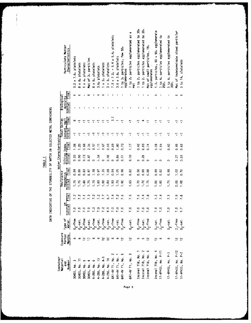
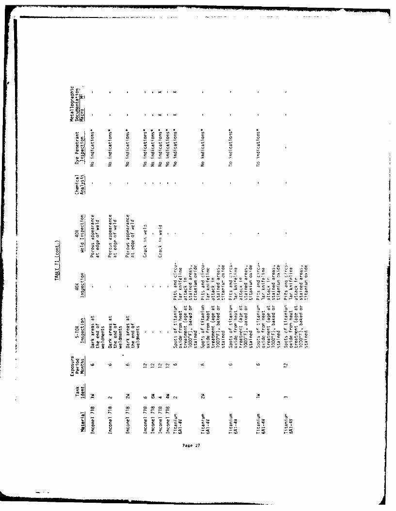
I Data Indicative of the Storability of Water in Selected 6Metal Containers
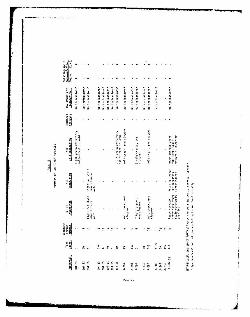
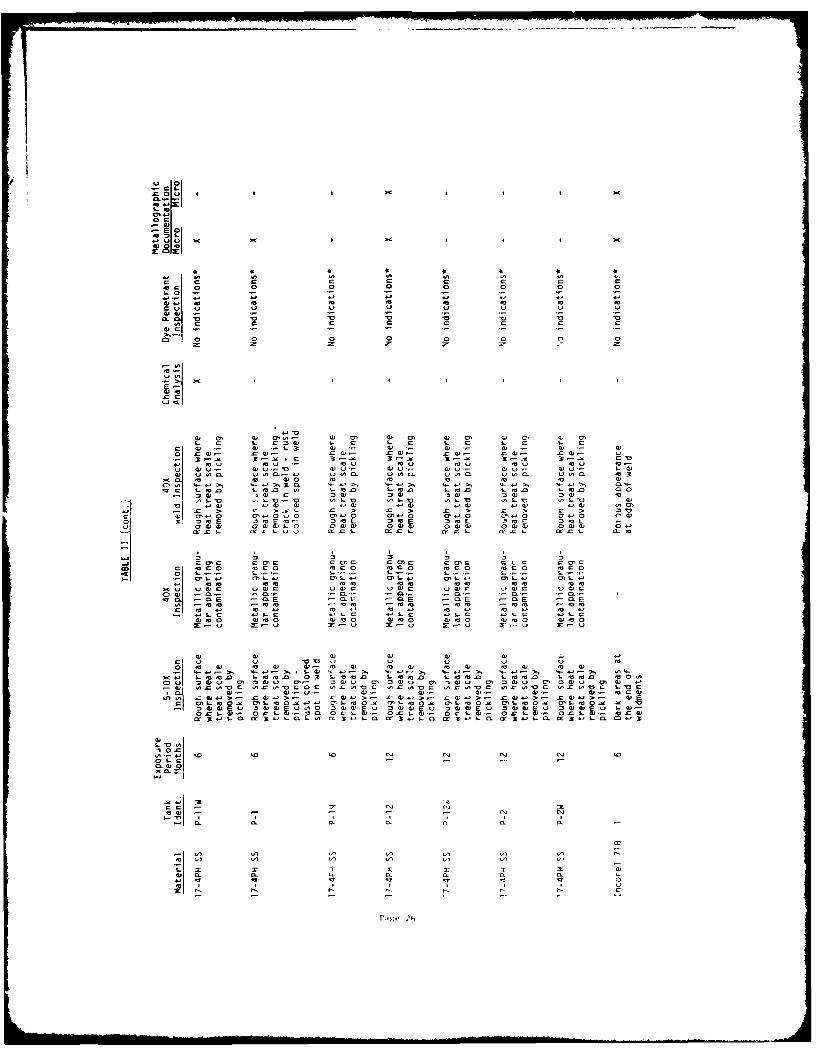
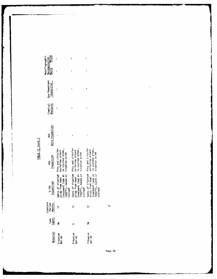
II Swnmnary of Container Analyses 25
vi
FIGURE LIST
Figure Page
1 304 Stainless Steel Containers, Magnification 1/3X i0
2 A-286 Containers, Magnification 1/3X 11
3 17-..-h H-1024 Stainless Steel Containers, Magnification 1/3X 12
4 Inconel 718 Containers, Magnification 1/3X 13
5 6AI-4V Titanium Containers, Magnification 1/3X 14
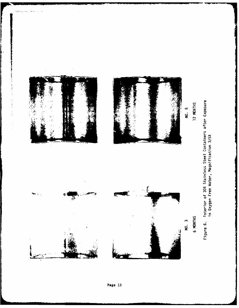
6 Interior of 304 Stainlecs Steel Containers after Exposure 15in Oxygen Free Water, Magnification 3/5X
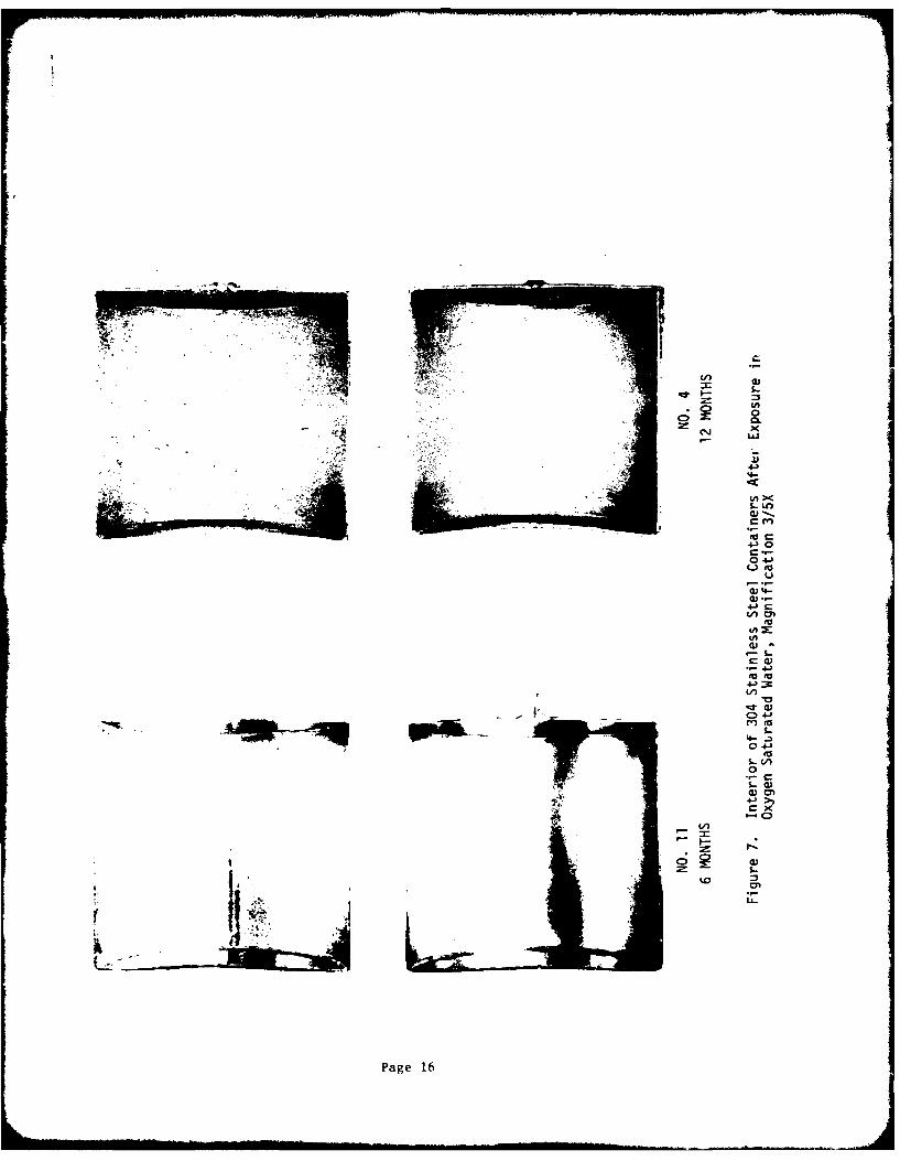
7 Interior of 304 Stainless Steel Containers after Exposure 16in Oxygen Saturated Water, Magnification 3/5X
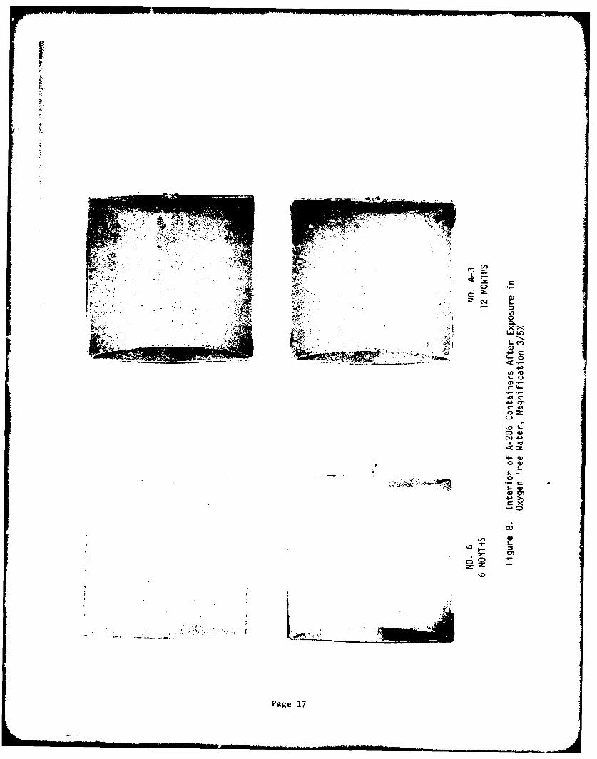
8 Interior of A-286 Containers after Exposure in Oxygen 17Free Water, Magnification 3/5X
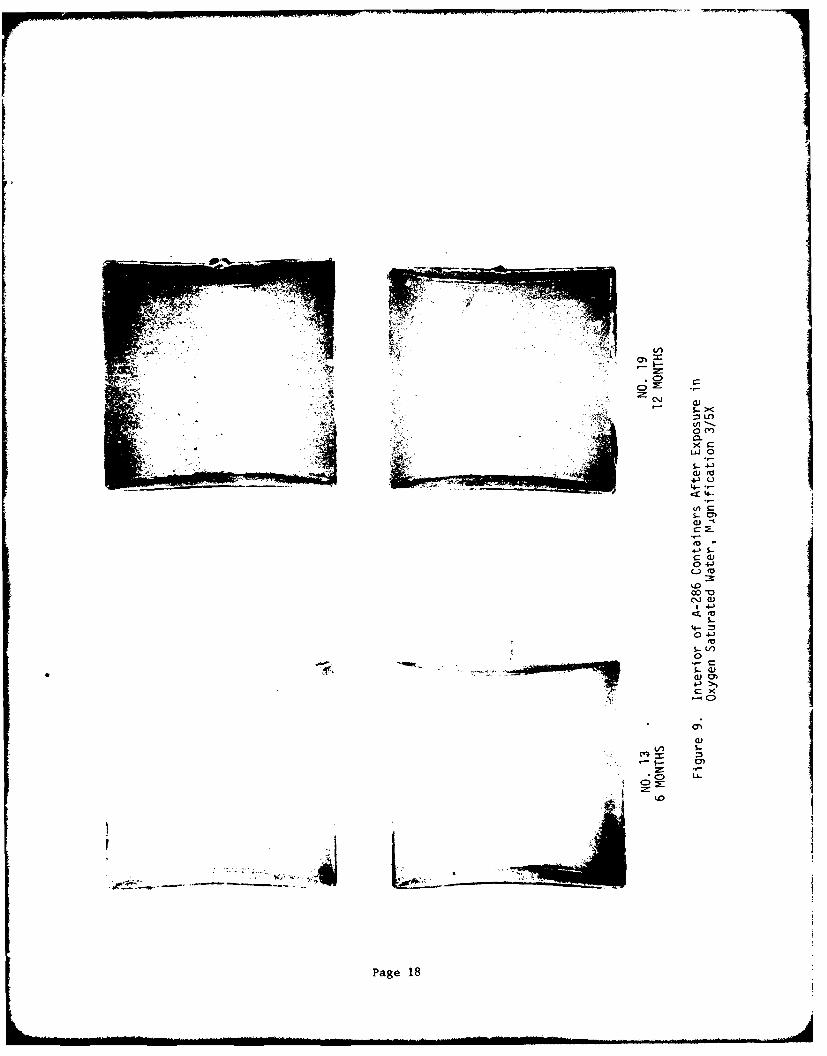
9 Interior of A-286 Containers after Exposure in Oxygen 18Saturated Water, Magnification 3/5X
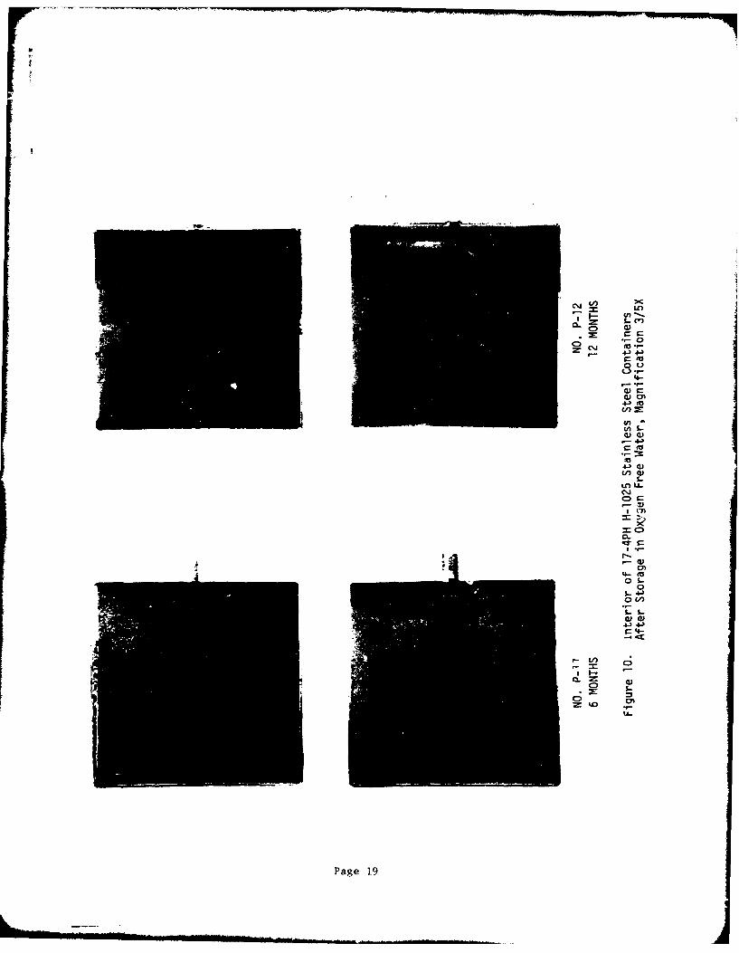
10 Interior of 17-4PH H-1025 Stainless Steel Containers after 19Storage in Oxygen Free Water, Magnification 3/5X
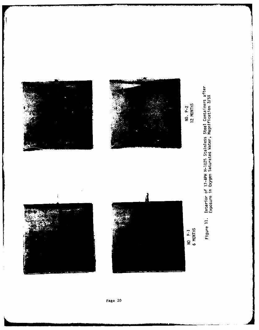
11 Interior of 17-4PH 1-1025 Stainless Steel Containers after 20Exposure in Oxygen Saturated Water, Magnification 3/5X
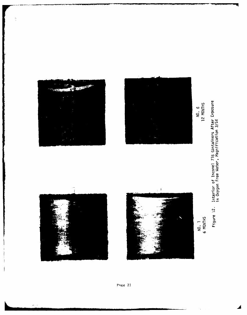
12 Interior of Inconel 718 Containers after Exposure in Oxygen 21Free Water, Magnification 3/5X
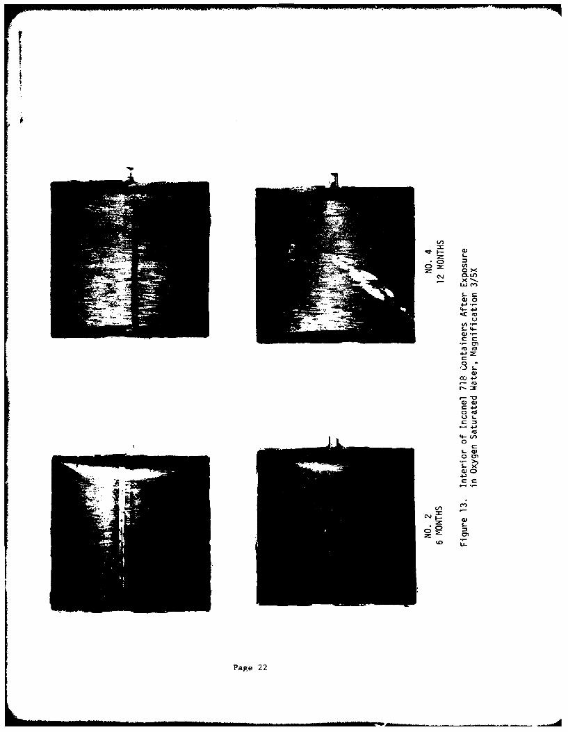
13 Interior of Inconel 718 Containers after Exposure in Oxygen 22Saturated Water, Magnification 3/5X
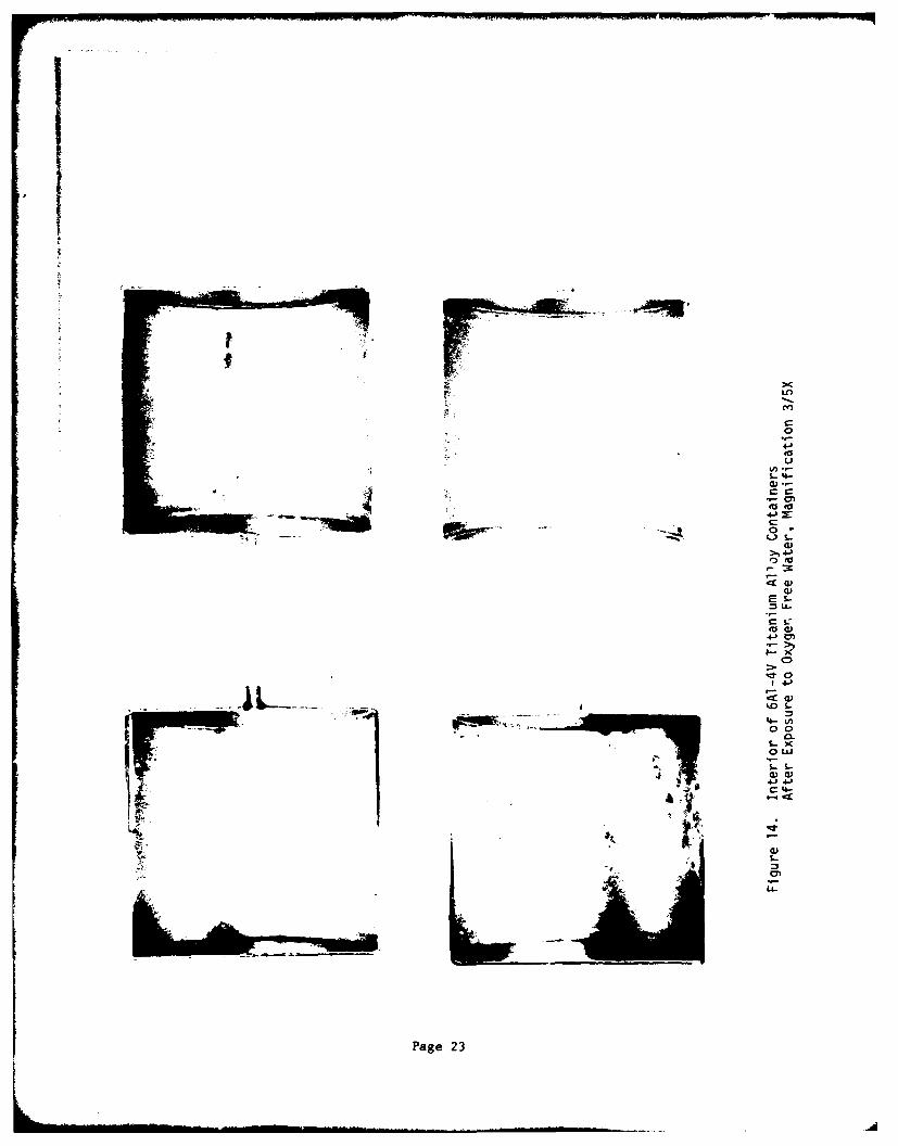
14 Interior of 6A1-4V Titanium Alloy Containers after 23Exposure to Oxygen Free Water, Magnification 3/5X
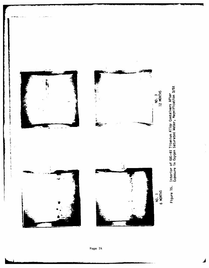
15 Interior of 6AI-4V Titanium Alloy Containers after Exposure 24in Oxygen Saturated Water, Magnification 3/5X
16 Opaque Appeaiinig Contaminant in Closure Weld of 304 No. 3 30Container (Arrows), Section of Weld Taken Through Contaminant(Lower Photo). Most of Contaminant Was Lost during Sectioning
due to Brittleness.
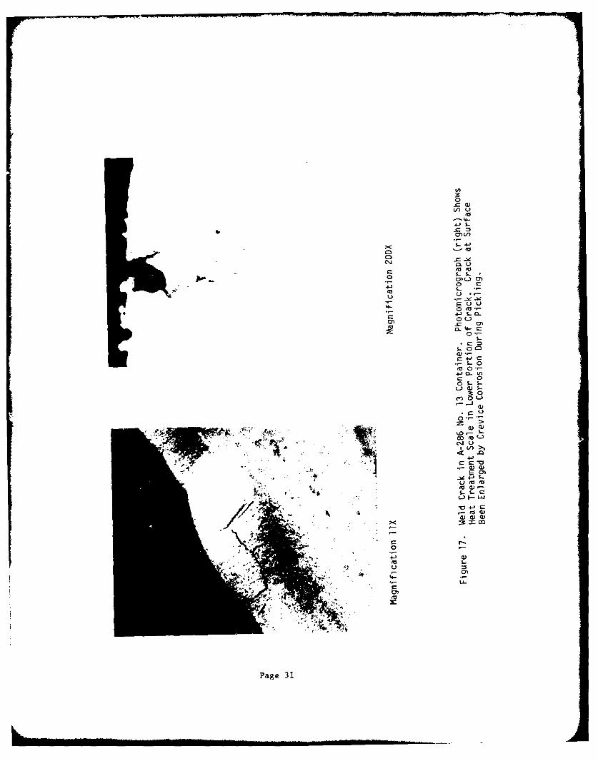
17 Weld Crack in A-286 Ne. 13 Container. Photomicrograph (right) 31Shows Heat Treatment Scale in Lower Portion of Crack. Crackat Surface Has Been Enlarged by Crevice Corrosion duringPickling.
vii
FIGURE LIST (cont.)
Figure Page
18 Weld Crack in A-286 No. 6 Container. Photomicrograph (bottom) 32Shows Enlargement of Crack by Crevice Corrosion duringPickling.
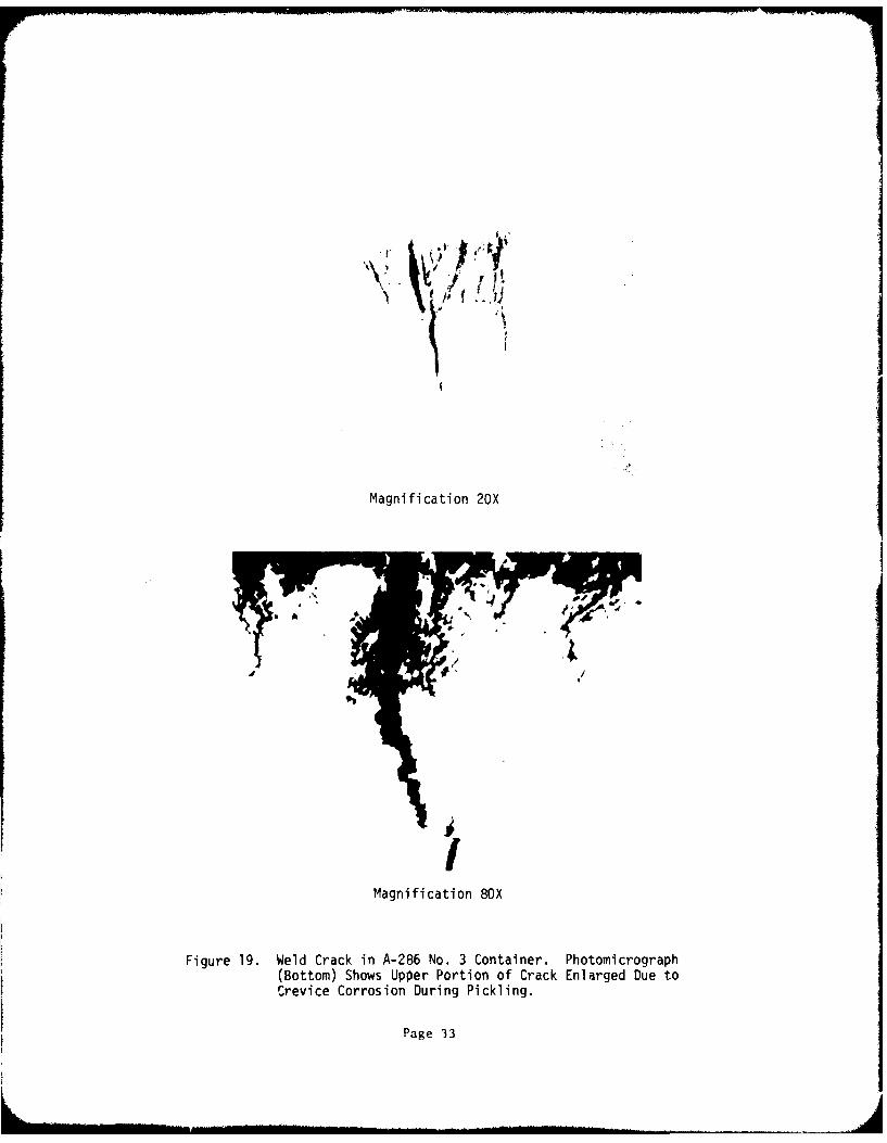
19 Weld Crack in A-286 No. 3 Container. Photomicrograph (bottom) 33Shows Upper Portion of Crack Enlarged due to Crevice Corrosionduring Pickling.
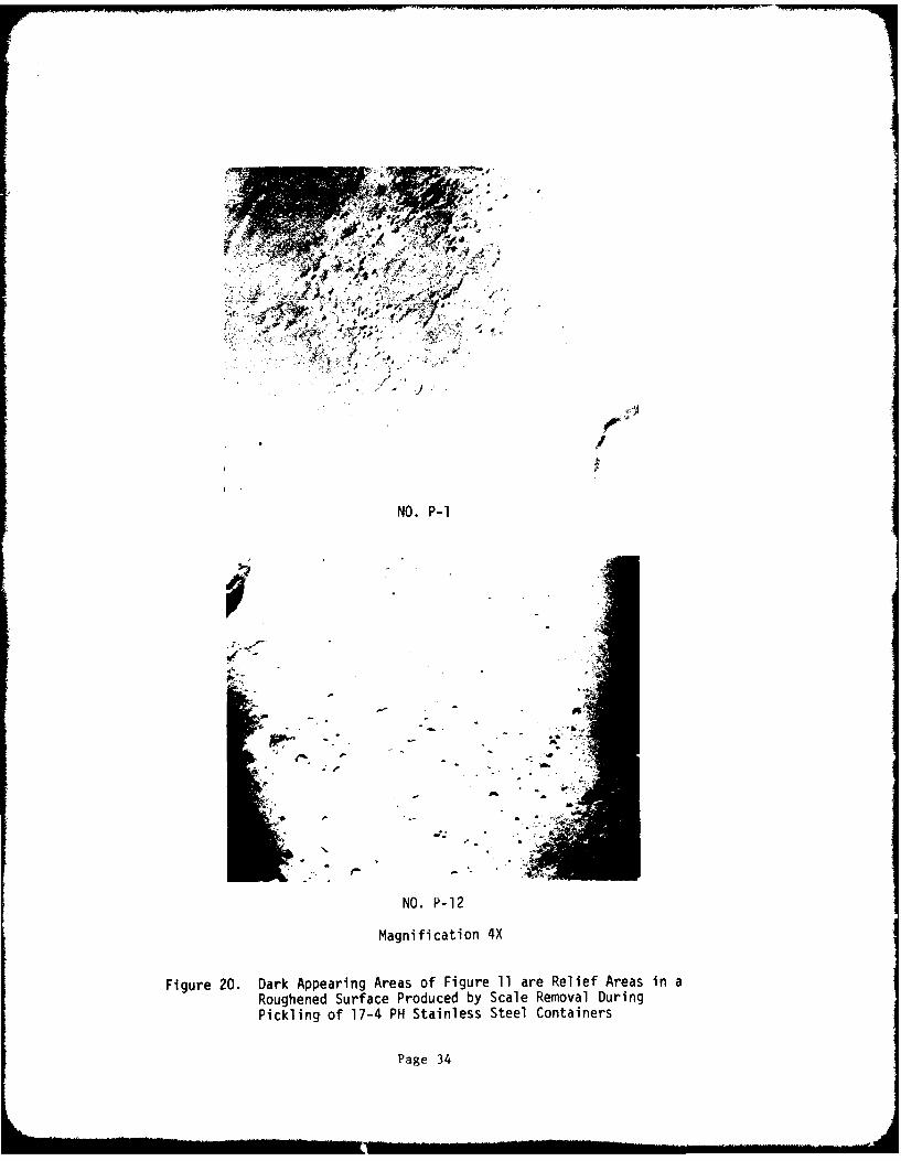
20 Dark Appearing Areas of Figure 11 Are Relief Areas ii, a 34Roughened Surface Produced by Scale Removal during Picklingof 17-4 PH Stainless Steel Containers
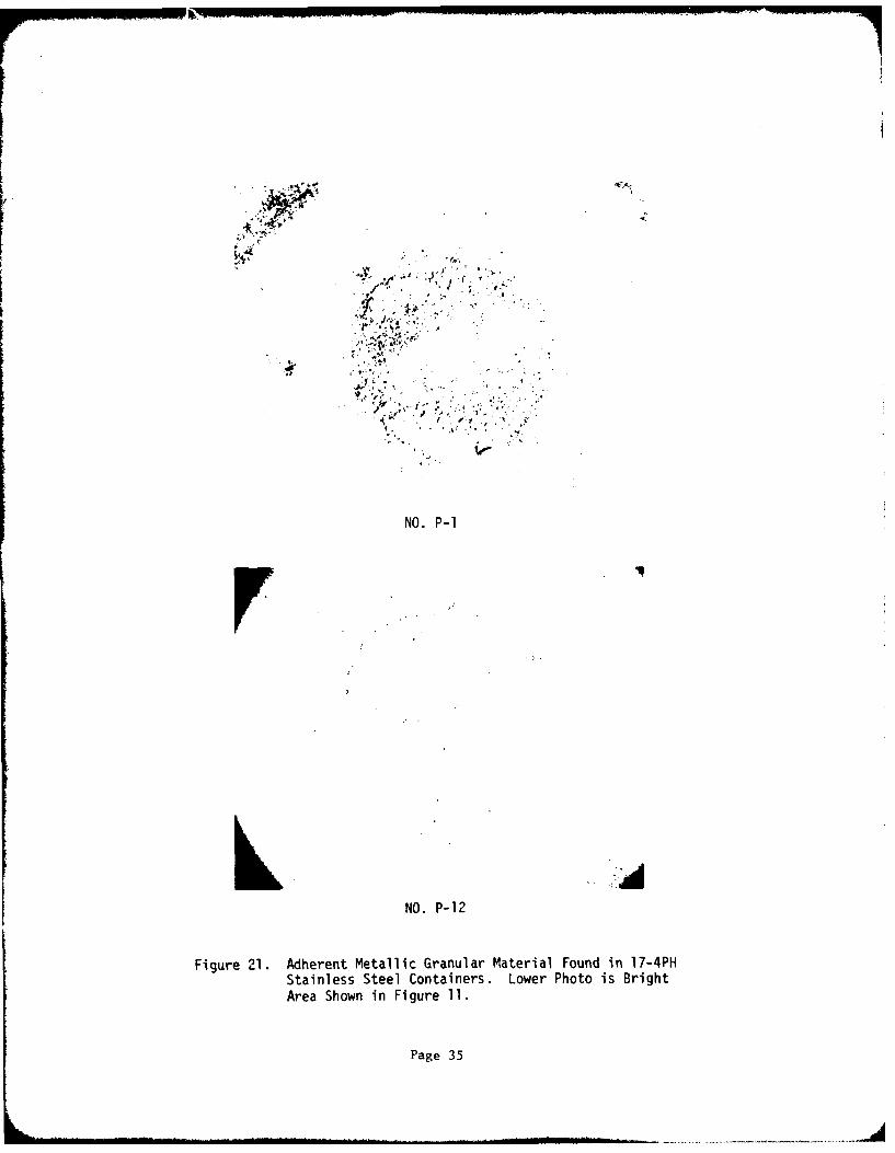
21 Adherent Metallic Granular Material Found in 17-4PH Staluiess 35
Steel Containers. Lower Photo Is Bright Area Shown inFigure 11
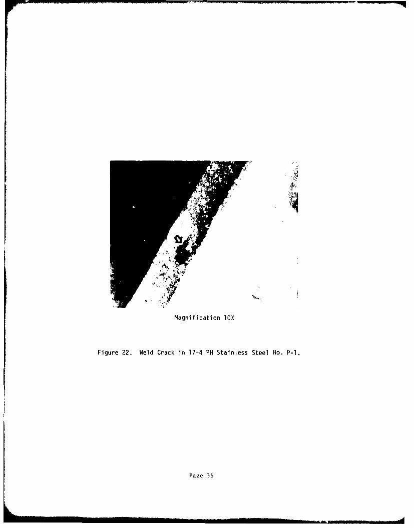
22 Weld Crack in 17-4 PH Stainless Steel No. P-1 36
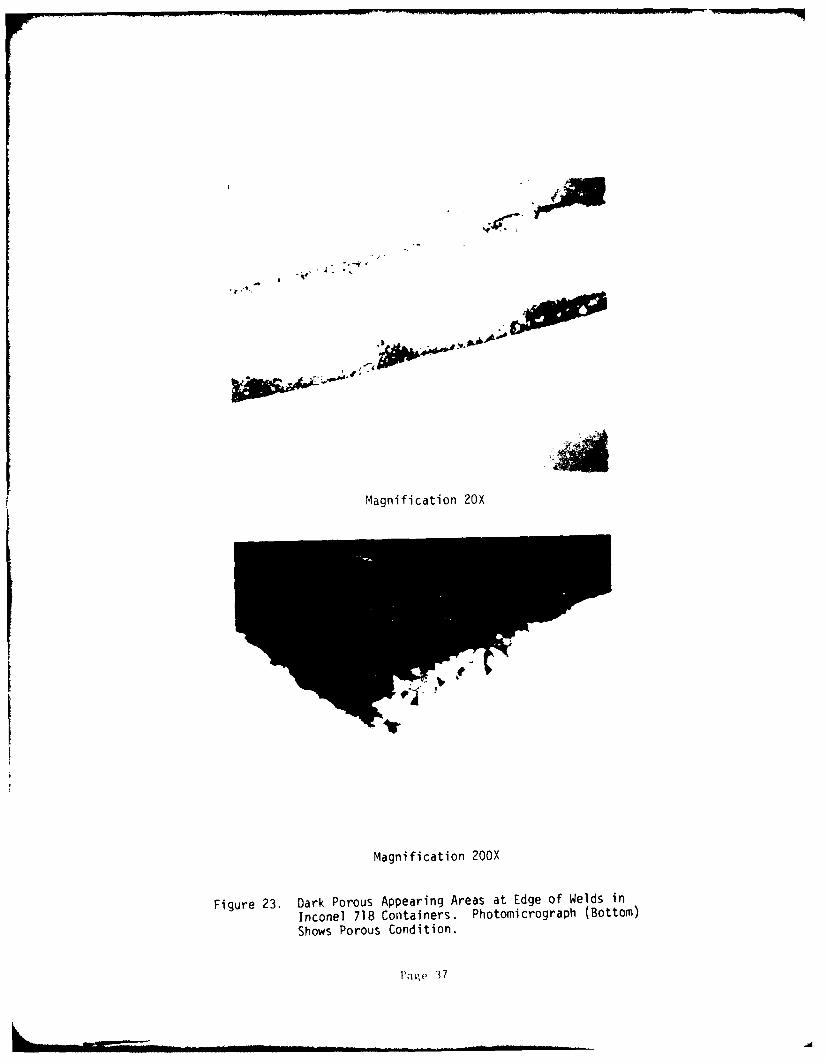
23 Dark Porous Appearing Areas at Edge of Welds in Inconel 718 37Containers. Photomicrograph (bottom) Shows Porous Condition.
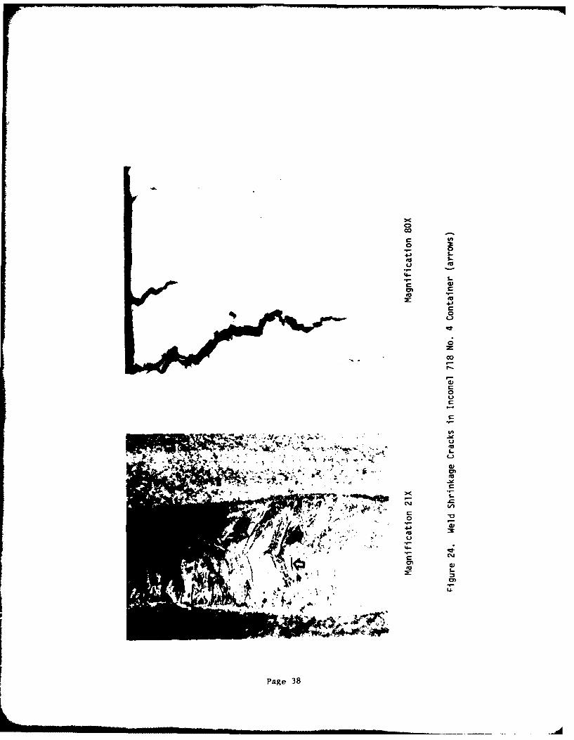
24 Weld Shrinkage Crackq in Inconel 718 No. 4 Container (Arrows) 38
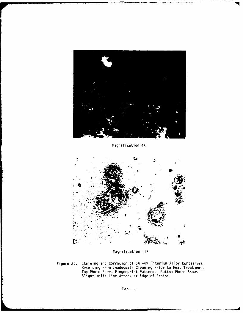
25 Staining and Corrosion of 6AI-4V Titanium Alloy Cc.tainers 39Resulting from Inadequate Cleaning Prior to Heat Treatment.Top Photo Shows Fingerprint Pattern. Bottom Photo ShowsSlight Knife Line Attack at Edge of Stains.
viii
-. 1p Pil p
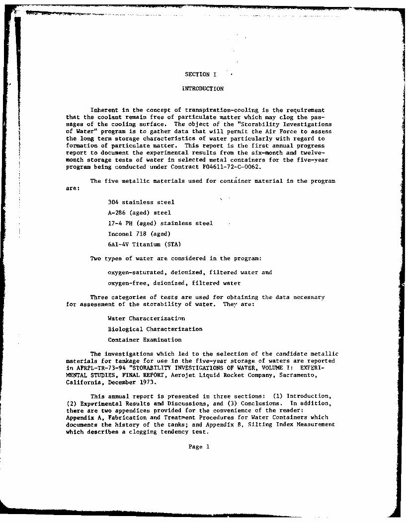
SECTION I
INTRODUCTION
Inherent in the concept of transpiration-cooling is the requirementthat the coolant remain free of particulate matter which may clog the pas-sages of the cooling surface. The object of the "Storability Investigationsof Water" program is to gather data that will permit the Air Force to assessthe long term storage characteristics of water particularly with regard toformation of particulate matter. This report is the first annual progressreport to document the experimental results from the six-month and twelve-month storage tests of water in selected metal containers for the five-yearprogram being conducted under Contract F04611-72-C-0062.
The five metallic materials used for container material in the programare:
304 stainless steel
A-286 (aged) steel
17-4 PH (aged) stainless steel
Inconel 718 (aged)
6AI-4V Titanium (STA)
Two types of water are considered in the program:
oxygen-saturated, deionized, filtered water and
oxygen-free, deionized, filtered water
Three categories of tests are used for obtaining the data necessaryfor assessment of the storability of water. They are:
Water Characterization
Biological Characterization
Container Examination
The investigations which led to the selection of the candidate metallicmaterials for tankage for use in the five-year storage of waters are reportedin AFRPL-TR-73-94 "STORABILITY INVESTIGATIONS OF WATER, VOLUME I: EXFERI-MENTAL STUDIES, FINAL REPORT, Aerojet Liquid Rocket Company, Sacramento,California, December 1973.
This annual report is presented in three sections: (1) Introduction,(2) Experimental Results and Discussions, and (3) Conclusions. In addition,there are two appendices provided for the convenience of the reader:Appendix A, Fabrication and Treatment Procedures for Water Containers whichdocuments the history of the tanks; and Appendix B, Silting Index Measurementwhich describes a clogging tendency test.
Page 1

SECTION II
EXPERIMENTAL RESULTS AN DISCUSSIONS
BACKGROUND INFORMATION
The purpose of the long-term storage tests is to demonstrate thatwater can be stored without formation of significant quantities of particu-late matter and with insignificant corrosion of appropriate metal containersfor time periods of at least five years in a controlled environment. The
background information is presented for the convenience of the reader anddocuments the initial conditions of the selected conta' :rs and waters priorto the storage periods. The discussion is presentai under the iollowingheadings: (1) Materials Selection, (2) Container Sterilization and Fillingand (3) Storage Conditions.
A. MATERIALS SELECTION
1. Waters
Based on the data derived from the preceding experimentalwork (Reference 1) it was apparent that both oxygen-saturated and oxygen-freewater were acceptable candidates for long-term storage tests. Further, thefiltration of the water through a 0.22 micron pore size absolute filter was
demonstrated to remove microorganisms effectively. Thus, the water used tofill the containers was passed through an activated charcoal bed to remove
organic compounds and through two mixed-bed ion exchangers to obtain waterthat had an electrical resistance value of I megohm/cm or greater. The water
was transferred through 0.22 micron filters into a 5 gallon stainless steelsupply tank. To ensure the saturation of the water with oxygen, filteredoxygen was purged through the water in the supply tank for a minimum of
15 minutes. To obtain oxygen-free water, the water in the supply tank wabheated to the boiling point of water for one hour while being purged withfiltered, nitrogen obtained from the boil-off of liquid nitrogen. The tankwas then pressurized with the filtered nitrogen, allowed t( cool to ambienttemperatures, and then repressurized with the filtered nitrogen. The outletof the supply tank was fitted with a Twin 90 Fiiter* unit to assure thesterile characteristics of the water used to fill the storage containers.
Ref. 1 E. M. Vander Wall, R. E. Anderson, G. R. Janser, StorabilityInvestigations of Water, Volume I, Experimental Studies,AFRPL-TR-73-94, Contract F04611-72-C-0062 (December 1973).
*A 0.22 micron pore size, absolute filter pack available from Millipore
Corporation, Bedford, MA.
Page 2
II, A, Materials Selection (cont.)
2. Metals
The selection of the materials of construction for the longterm storage test containers was based on the results of the laboratoryinvestigations (Reference 1). The aluminum alloys were eliminated from con-
sideration due to their introduction of insoluble corrosion products whichare a source of particulate matter in the water. Because test results on theremainder of the seven candidate materials were not discriminatory, choicewas made on the basis of selecting not more than one alloy from each class ofmaterial. The one class of material with more than one representative was the18% chromium - 8% nickel austenitic stainless steels, i.e., 304L, 347 andArde-form 301. Hence two of these materials were eliminated to provide thefive materials required fur container fabrication. The 304L stainless steelwas selected due to its attractiveness as an expulsion bladder material.Hence, the selected materials are: 304L stainless steel, A-286, 17-4PHstainless steel, Inconel 718 and 6A1-4V titanium. During fabrication, some304 stainless steel parts were incorporated into the 304L stainless steelcontainers and consequently the containers are identified as 304 stainlesssteel containers. The fabrication procedure s, the heat treatment cycles, thecleaning procedures and the passivation procedures to which the containerswere subjected are presented in Appendix A of this report.
B. CONTAINER STERILIZATION AND FILLING
FoLlowing the final rinsing with filtered, deionized water, andsubseque..t drying of the containers in a vacuum chamber, the containers werewrapped with reusable sterilization paper. The wrapped containers were thensterilized in an autoclave at 250*F with 15 psig stcam for 30 minutes fol-lowed by a 30-minute drying period. The containers were then stored in thepaper to maintain their sterile condition.
All the steps required to fill the containers with water were con-ducted in a sterile, laminar-flow bench. The tanks were removed from thewrapping paper in the laminar flow bench. The tanks were weighed empty; thenweighed when filled completely with sterile water to determine the totalvolume of the tank. The water was drained out and the tank was rinsed oncemore with the sterile water. A sample of the rinse water was checked for pH,conductivity, and Silting Index (see Appendix B). If the values indicatedthat particulate matter and dissolved species were not present, the tank wasconsidered ready for filling; if the values indicated that contaminants werepresent, the tank was rinsed until there was no evidence of contamination.A Silting Index value of I or less for the rinse water when using the filterwith a cross-sectional area of 1.0 mm2 was used as the criterion that nosignificant quantity of loose particulate matter remained in the containers.
Page 3
II, B, Container Sterilization and Filling (cont.)
Before the final filling with oxygen-saturated deionized water,the tank was purged with oxygen from a filtered supply. The tank was thenfilled with the water and a sample was withdrawn for pH, conductivity, andSilting Index measurements. The ullage was adjusted to the ten percent valueby weighing the container and its conLents; the ullage space was purged withthe filtered oxygen; and the container was capped with a sterile, taperedplug made from the same material as the container. 'Iie plug was seated inthe fill-tube by use of a hammer. The containers were filled with the oxygen-free, deionized water in an analogous manner except that filtered nitrogen wasused instead of oxygen for purging and blanketing the container.
The final sealing of the containers was accomplished by GTA weld-ing the fill-tube/plug interface. The welds were inspected visually for anyapparent anomalies. None were found. Then the containers were labeled forthe long-term storage tests and placed in plastic bags.
The sampling plan for the long-term storage tests is to removeone container of each material with the two types of water for inspectionand evaluation every six months for a period of five years. The contentswill be characterized with respect to pH, conductivity, particulate content,and biological activity; and the containers themselves will be subjected tometallurgical examination if the other test data indicate that this isrequired.
C. STORAGE CONDITIONS
The storage area for the water containers is an air-conditionedroom which is monitored continuously to document that the temperature is main-tained at 70 + 1OF and that the relative humidity is maintained at 50 + 25percent. The containers are stored in a closed metal cabinet to protect themfrom an accumulation of dust and the containers themselves are covered withplastic bags to prevent direct contact with foreign metal surfaces. Thecontainers are visually examined on a weekly basis.
WATER CHARACTERIZATION
After six months of storage at the conditions defined above, andagain after twelve months of storage, Len containers were removed for evalua-tion. They r nsisted of two containers of each selected material, one con-taining oxy, a-free water and the other containing oxygen-saturated water.
A. PROCEDURES
After the six-month storage period, the water containers werewashed with deionized water and then placed in a stnrile, laminar-flow benchfor further handling to remove the stored water. The outlet of the contairer
Page 4
II, A, Procedures (cont.)
was rinsed repeatedly with filtered, deionized water to remove any contami-nants and then briefly subjected to a torch flame to sterilize the exteriorof the metal. After the twelve month storage period, the water containerswere immersed in a 95% ethanol bath prior to placement in the sterile,laminar-flow bench; and then after removal from the bath and placement in theflow bench, the residual alcohol on the tank surface was removed by burning.The outlet of the container was repeatedly exposed to a torch flame to assurea sterile condition. All the containers were opened in an identical manner.A sterile tubing cutter was used to sever the fill tube. The water wasexpelled from the containers by inserting into the fill tube of the containera sterile stainless steel capillary tube through which filtered, gaseousnitrogen was passed while the container itself was inverted. The firstseveral ml of water were used to flush the tube and were discarded. Subse-quent samples of water were collected for measurement of pH, electrical con-ductivity, dissolved solids, particulate matter, flow behavior, and for char-acterization with regard to possible biological contamination.
The measurement of the pH was made using a standard pH meter witha calomel reference electrode and a glass indicator electrode. The electri-cal conductivity of the water was measured using a Balsbaugh ConductivityMeter, Model No. 900-.O1T with a standard dip cell. The dissolved solidscontent of the water was determined by evaporating 200-300 ml samples of thewater to dryness and weighing the residue. In addition, any particulate mat-ter which collected on the 0.8i filter of the flow behavior device was exam-ined microscopically and sized. The flow behavior of the water was evaluatedusing a Silting Index Apparatus (see Appendix B for description) which per-mits filtration of the liquid through a known area (1.0 mm2) at a constantpressure so that the flow decay due to the presence of particulate matter maybe recorded as a function of time. The standard method of the test isdescribed in ASTM F52-69. The data are reported as a silting index values;the greater the value, the greater the degree of contamination by small par-ticulate matter.
B. DISCUSSION OF RESULTS
The data obtained from the tests are presented in Table I. Thedata obtained during loading of the containers with Lhe water initially areincluded in the tabulation to facilitate comparison and identification oftrends. The baseline data are labeled as initial and the data from the six-month and twelve-month storage tests are labeled as final.
The significant items to note from the data are that: (1) thereare generally slight increases in the pH values of the waters during storagein the containers; (2) as expected there is a general decrease in the resis-tance value of the waters due to an increase in ccncentration of ionic
Page 5
0 0 S-0 vIG (') 4' 41
01 41'41 a
CL C) 4' 4- o)4 4' 0
W; 4- m Vn a, 0(
41o . A m m-C mL 14'0 A C 0~
Ct Wt 0 Ct 0'
Z0 0! lat0- 0 0
IV 0i Co U I- I- a,00 0 0 L 0 .
4'0) -0 a'* 4S.. 0 0 0 0 0 0 0 0 4'o 4-4 E a '1 ' 4-
0. A o 00 0 0 -t4' 0 0 ' 0 CC) X.
.o . .. t .~ .. .. .2 4 .. .. C
02 . . .' 0. . .0. . . . -tL ,-! t. zf IO A AI
0 r- t C C
0*
L) CD' CD C) CD C) 1 1 1 CD c. C)c D
toc l- a
x U C>
Ec 00 , O r C ~ D 00 0 D " C
LU CD CCC DC D DC DC C)CDC
M- -
0S 0 1. 4 4
~ ' - C) ( C) - C) C) C> C C) C) C) C) C) C) DC C) C
j Ln
0 LI. CCL 0 4x
-. ~ 0; C<O C O C;' N C O 0 ' C )0 CO 0' CL CL CL a,
-- '~ ~~ 02- .. . . . . .-. CU C) C DC)' C), ; C) C) C): C): C) C) C ) ) C
o 0 ) V) C) In 10 C) C) C) C) C) C) U) C) C) m)C ))CIn to N. L. WO WV W. a, CO CO 0'0 0' t .C . O C )C
U3 0a4'. . . . . . . . . . .10 1041-
Page
L . . )(J(4N .0 . o U o O N 't
I
II, B, Discussion of Results (cont.)
species but the ',alues indicate concentration levels which are equivalent to
less than one part per million of metallic ions; (3) the Silting Index valuesindicate the presence of a slight amount of particulate matter in the waterbut the concentration levels are insignificant with regard to the quantitiesof particulate matter that are required to cause clogging in flow passages;
(4) the total solids content of the water in most instances was below a mg/iwhich corresponds to the level of detection in the procedure used and theconcentration level of solids in the waters which contained measurable solids
was so low that the quality of the water is not impaired; and (5) the resis-tance values, Silting Index values, and total solids values are not signifi-
cantly different between the six- and twelve-month storage periods.
The particulate matter that was collected on the filters appearedto be that which had continued to adhere to the container walls during thecleaning, pickling, passivation, and flushing procedures prior to fillings.
In summation, the waters were all suitable for use in transpiration-coolant
devices.
BIOLOGICAL CHARACTERIZATION
A. PROCEDURES
200 ml samples of the water taken from the storage containerswere filtered through pre-sterilized filter pads which were transferred
directly to sterilized Petri dishes containing suitable nutrients for directcolony counting after a suitable culturing period. The procedures are
described in Standard Methods for Analysis of Water and Waste Water, AmericanPublic Health Association, 13th Edition (1971) and Biological Analysis of
Water and Waste Water, AM 302, Millipore Corporation, Bedford, Mass. (1973).In addition, any biological organisms present were washed from the filter
surfaces with a sterile buffer solution and placed directly in sterilenutrient solutions for culturing so that adequate samples are available foridentifying the genus and the specific species of micro-organisms that might
be present in the stored water. Based on the lag-period prior to growth of
micro-organisms which have been observed earlier in the program (Reference 1),the tubes containing the nutrient solutions were incubated for periods up toone month.
B. DISCUSSION OF RESULTS
The results obtained by culturing samples from the water contain-
ers are presented in Table I under the heading "Biological Activity". Thelack of any indications of micro-organisms being present is denoted by a
minus sign; if growth was indicated in either the culture tube or on the fil-ter pad, but not on both an "X" is used; and if growth was found in both the
Page 7
II, B, Discussion of Results (cont.)
culture tube and on th4 filter pad a plus sign is used as an indication of thepositive result. In nd instance was a positive result obtained.
:= After a month of incubation of the samples from the six-month
storage tests there was no indication of micro-organism growth on the pre-sterilized filter pads. Slight growth was observed in the culture tubes con-taining washings from the 304 stainless steel containers and one of the A-286containers. The number of micro-organisms present was extremely small asindicated by the negative results with the filter pads and the slight amountof growth in the culture tubes. There was no evidence that any biologicalgrowth occurred during the six-month storage period. The micro-organismsfound were identified as an Aeromonas species.
After a month of incubation of the samples from the twelve-monthstorage period, one of the culture tubes containing the washings from anInconel 718 container exhibited growth, but the filter pad was negative. Themicro-organisms present were identified as most likely being Pseudomonasaeruginosa. The filter pads used for the culturing the contents of both ofthe 17-4 pH containers, one of the 304 stainless steel containers, and one ofthe A-286 containers exhibited growth, but the corresponding culturetubes were all negative. The micro-organisms were identified as Pseudomonasspecies. Again there was no evidence that biological growth occurred duringthe twelve-month storage period in any of the containers.
The species that have been identified as being present in this
random manner are isolated readily from water and from around sinks in labora-tories. In reviewing the sampling procedure for the biological characteriza-tion, it appears that the procedure with repeated insertion of the cannula toexpel water from the containers may be vulnerable to contamination by micro-organisms. The procedure is being modified so that future sampling will notbe as susceptible to contamination.
In summation, the biological testing has shown that there is no
evidence for any biological growth occurring during the storage periods.
CONTAINER EXAMINATION
A. PROCEDURES
After removal of the water from the containers by draining, theywere vacuun dried frr a day to insure sectioning in a dry condition. The con-tainers were then photographed to document their general appearance. Section-ing of the containers to expose the internal surfaces was done by sawing with-out coolant to prevent contamination. Subsequent handling of the containerhalves was carefully performed to avoid touching the interior surfaces. Theinternal surfaces were then photographed to document their general appearance.
Page 8
II, A, Procedures (cont.)
r
Further general examination at magnifications from 5 to lOX werecondu ted on all interior surfaces to further define conditions found in theaforementioned visual examination and to reveal additional suspect areas.Selected discrepancies were then identified for additional examination atmagnifications to 40X. All welds were examined at 40X magnification. Repre-sentative discrepancies were photographed at magnifications adequate fordefect definition. Those defects requiring further definition were examinedmetallographically to establish their cause and extent. Sections takeneither through or immediately adjacent to the affected area were mounted,polished, and examined. Photomicrographs were taken to document the condi-tion. Contaminants or corrosion products capable of being sampled wereanalyzed by X-ray diffraction and emission spectrographic techniques toestablish their composition. All interior surfaces were dye-penetrantinspected to determine whether any defects were undetected during the visualexaminations. No additional indications of defects were found.
B. DISCUSSION OF RESULTS
The results of the container examinations are discussed underthree headings: (1) General Visual Examination, (2) Metallographic and Chemi-cal Analyses, and (3) Implications of the Results of the Examinations.
1. General Visual Examination
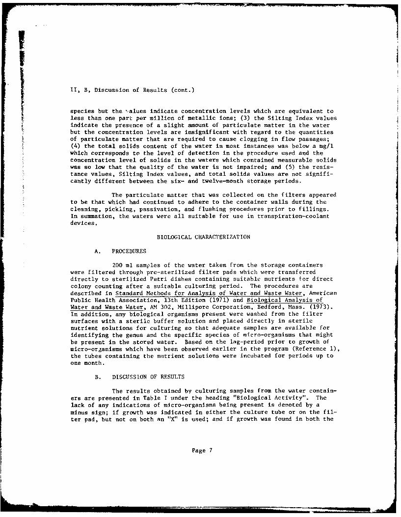
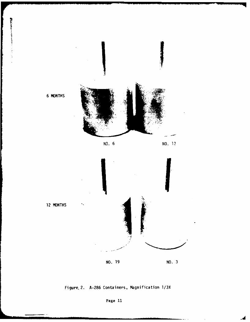
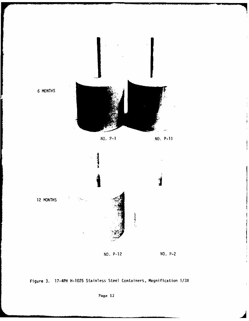
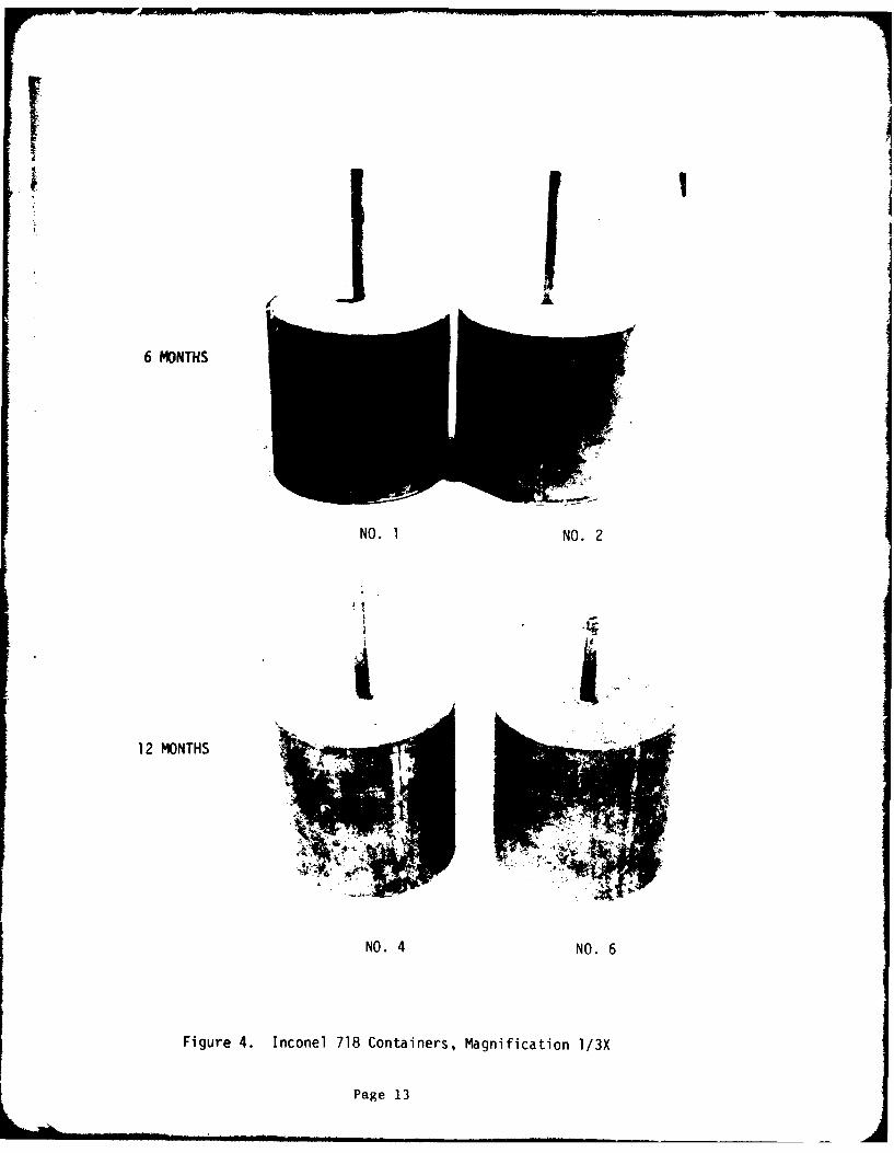
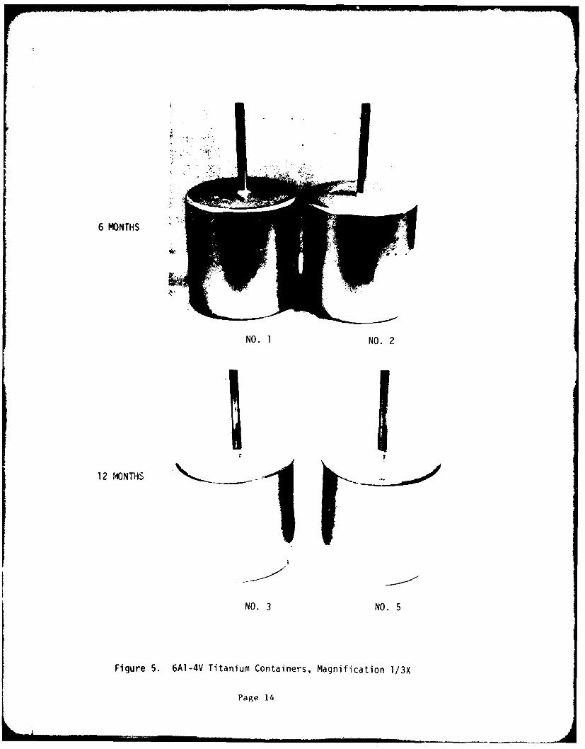
The external appearance of the containers is documentedphotographically in Figures I through 5. The internal appearance of the con-tainers is documented photographically in Figures 6 through 15. Examinationof these surfaces without visual aids showed full penetration for the fulllengti of all weldments. Other conditions resulting from fabrication andcleaning procedures were: (1) etching of A-286 containers during pickling;(2) isolated dark areas, a tightly adhcrent smut, and isolated shiny depositsof material in the 17-4pH stainless steel containers; (3) a tightly adherentsmut in the Inconel 718 containers; and (4) isolated areas of residualtitanium oxide, localized circular areas of attack, and a general mottledappearance including fingerprint contamination in the 6A1-4V titaniurcontainers.
No difference could be determined between the 6-month and12-month exposure containers, or between those holding the oxygen-free andoxygen-saturated water.
2. Metallographic and Chemical Analyses
A summary of the analyses performed on the containers Ispresented in Table II. The results of macro- and microexamination are shown
Page 9
6 MONTHS
NO. 3 NO. 11
12 MONTHS
NO. 4 NO. 5
Figure 1. 304 Stainless Steel Containers, Magnification 1/3X
Page 10
6 MONTHS
NO. 6 NO. 13
INU
12 MONTHS
NO. 19 NO. 3
Figure.2. A-286 Containers, Magnification 1/3X
Page 11
6 MONTHS
NO. P-1 NO. P-li
12 MONTHS
NO. P-12 NO. P-2
Figure 3. 17-4PH H-1025 Stainless Steel Containers, Magnification 1/3X
Page 12
6 MONTHS
NO. 1 NO. 2
12 MONTHS
NO. 4 NO. 6
Figure 4. Inconel 718 Containers, Magnification 1/3X
Page 13
6 MONTHS
NO. 1 NO. 2
12 MONTHS
NO. 3 NO. 5
Figure 5. 6AI-4V Titanium Containers, Magnification 1/3X
Page 14
(A -
4-)
0
4-) 4-
(AC,)
s- 0)
C;C
4-
I-
Page 15
41 PIN.
.)0CL
C
a) .-4j C
S..
04J
Sc,
a, +j
0 41
00
NWW
Page 16
S- n
4-0
4-
o 7:
00 0)C'J 4J.
0)
0C)
L.
Page 17
.0 C-
C'4
uLo 0
4-) U
4-'
14-
eo 4-':
01
-0
0 )L/) S.-
o~
.- ,- C'
*0) LL-
Page 18
.j 0z.r 41
14-
Ln
4-) Wj
- iCI c
=00
4-1'0 V
41 41)
C: 4-
~Lof)=- =
Page 19
4)4-)
4n-s-Ov
4/ )C'j c
ii- -'0
'4-
V) X:I
-)
-)
V )
.)
o
4) 0
4- CL
o -
Page 20
2= 0
Lii
4) LO4-'-,
4-)
1.-
.-
0
L)O
V4-'AC:
0 mx
C c
-' a
ILL
0,.
aua
u~o
C4-)- ro.
L 4-
cc
00
oo
4) C
Q)C; p~
to LA
PagUS2-
LA
C
L 4-
0 0CL
LL)
to.
Page 2-
E)
4-4 J
4J 4J
tC
4- ca*.-
1- 00-
0) 0
LJ
Page 24
0 cI
Co c cc Q c c c c C0 440
44- 0 0 0 0 0 0' 0 0 0 0 0 0 0 0 LA
OC 0 w 0 0 0 0 0 I 000I
-4L U 0 KU C, w ~ U 0 0 0 0 0
C)C
L> 4
cu 0
'4- 0 '
CL ELS S-L t
0 4 £ a>a- a
0. 6- c0 "1 10 10 1
p -a w0 C - C C Q
00 3GLC 044-
ZEL ~ '~
tn 0) V,1 0 100.m 0L
01 01. OJ co 00 m 4O
c-S C L. CC W' 0.4-
Page 25 W * 03
T 10.C-
0 0
Cu
.- 44-
4-C - -l 3C 1 .
OC M 0, 0.a-~ ~~~~ Q, 4I4 -I4I4I4
W,4 m 0 0 C7 0 L0 0
40 4 E .- *.-E- mME0. 4,v d 0 w j 0 w 0
Q2 L
ts- C I
M1 10 M 'o M0
WII 0 0), 0 a,0a 4
C ~ ~ ~ ~ ~ ~ c w02 CI 0C CI 02Cl
do M.I 0 S-M 0 4 00 m4 0 m) MI M- 0
Ut-C rt- C.I. 4tC C ctC U-
0 T ) 41 0 41 0 41 V u- ? 41 M 41 , d)1a
Ou OI 0 r-1 :3 0 0 ' 4 0 ' 04z( 0 0410 %- 04U 0 1 '-41 .A ,Cx tn2nOO 41r13C M X~v ZnLIC .I..V CL AVC 3tD
t- 0 r_
0CC0.41 0
06- 0
-4
-z
-
4 4 4 4 4
4.4~~~~~~~ I 1 - .4 !E - 1 101aI0
wJj 4 4 4 0 .W4 4 4 04M44 0 mV I
CU ~ ~ c oI Ma oI U U U U
%- 01o u
C I
lo>4 mW a c m a l a ., C ma
oC 4o 44 m4)m4 m o
m c .r 4 44 E4 a, E4o E0A -'D 0... 0acD4 a aD v 5
A~~~~ ~ LI 00 00 00 1- 1
0.0 ~ 0 0ala .) E
a1 o4 o1 04 o1 o4 mZ 4
LU ~ ~ ~ ~ ~ ~ ~ ~ ~ ~ Pg 274tO 04 tO (4 00 44 j0 04 tl
u ur- 104C I L
-4,
'o C E
m 00
0
'C)
4) 0 (VZ) 0 E~
00oL 0 a ' ' ~.I M 0 I) * 0 4:
c4 4,.) 4,4)
(DC~ ~ ~ ag 28EO C£ ~ C
II, B, Discussion of Results (cont.)
in Figures 16 through 25, with each photomicrograph being shown with its cor-responding photomacrograph. The results of the analyses are discussed belowfor each container material.
a. 304L Stainless Steel
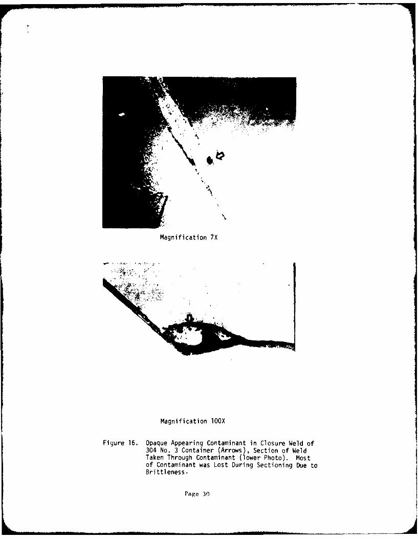
The one discrepancy found in the 304 containers was asmall piece of opaque refractory-appearing material in the weld of ContainersNo. 3 and 5, Figure 16. The small size prevented identification by chemicalor instrumental analyses. A metallographic specimen was prepared from No. 3container; however, most of the material was lost during specimen preparationdue to brittleness. In addition, a light red stain appeared adjacent to theclosure weld of container No. 11. The cause of the stain co,'ld not be deter-mined; its size was 0.15 x 0.01 inch.
b. A-286
A total of four cracks were found in the end closurewelds; one crack appearing in Containers No. 13 and A-3, and two cracksappearing in Container No. 6. Three of the cracks are shown in Figures 17through 19. The cracks appear in both the oxygen-free and oxygen-saturatedwater containers and are attributed to shrinkage stresses occurring duringthe welding process. These defects were expected, due to the poor weldabilityof the A-286 material. The photomicrographs indicate a corrosive attack ofeither part or all of the weld crack. This behavior is attributed to crevicecorrosion during post-heat treatment pickling of the containers. The presenceof scale within the crack prior to heat treatment verifies the conclusion thatthe attack is not a result of water storage. No evidence of corrosion result-ing from water storage could be found.
c. 17-4PH (H1025) Stainless Steel
All the containers were in a similar general condition.Examination of the interior surfaces at moderate magnifications revealed thatthe dark areas shown in Figures 10 and 11 were relief areas on a surfaceroughened by scale removal during pickling as shown in Figure 20. This exami-nation also revealed that the shiny deposits seen with the unaided eye had theappearance of being metallic and granular as shown in Figure 21. Samples ofthis material, which adhered tightly to the container inner wall, wereexamined by emission spectrographic and X-ray diffraction analyses. Thesample was identified as the container material, 17-4PH stainless steel. Asingle weld crack, shown in Figure 22, was found in an end closure weld inContainer No. P-1. This crack also occurred during welding and is not aresult of the water storage.
Page 29
I I
Magnification 7X
Magnification 1OOX
Figure 16. Opaque Appearing Contaminant in Closure Weld of304 No. 3 Container (Arrows), Section of WeldTaken Through Contaminant (lower Photo). Mostof Contaminant was Lost During Sectioning Due toBrittleness.
Page 30
0
V) uto
-4-
S.- 4--
as0
0S.- S-
CU -N -x0) to.-
'4- OCU'
0*.-
5.- 0 Lnd)-
C4-i CS- 0-
4-' QC U.C 0
0 L) s- s 0
0
'I0- 5.-
4-'
E 0')--. 4-) L-
-0 4-)d) 00)
0
4-)
Page 31

A- -
MagnifiLcti-n 20X
Magnification 200X
Figure 18. Weld Crack in A-286 No. 6 Container. Photomicrograph(Bottom) Shows Enlargement of Crack by Crevice CorrosionDuring Pickling.
l'Pae 32
144
Magnification 20X
[ • I .
%I
Magnification BOX
Figure 19. Weld Crack in A-286 No. 3 Container. Photomicrograph(Bottom) Shows Upper Portion of Crack Enlarged Due toCrevice Corrosion During Pickling.
Page 33
~~-NO P-1F- /
NO. P-1
NO. P-12
Magnification 4X
Figure 20. Dark Appearing Areas of Figure 11 are Relief Areas in aRoughened Surface Produced by Scale Removal DuringPickling of 17-4 PH Stainless Steel Containers
Page 34
... O .. .. P
N PI12
u 2. AS s S l C
Ar ea Shon i i re -11.
-g 35
..'a_. . , J .:
A, ~ t .
NO.P p1
r/
NO. P-12
Figure 21. Adherent Metallic Granular Material Found in 17-4PHStainless Steel Containers. Lower Photo is BrightArea Shown in Figure 11.
Page 35
ALIV
Magnification lox
Figure 22. Weld Crack in 17-4 PH Stainiess Steel No. P-1.
P'age 36
e,4
MagifcatonMA
Magnification 20X
Magnification 200X
Figure 23. Dark Porous Appearing Areas at Edge of Welds in
Inconel 718 Containers. Photomicrograph (Bottom)
Shows Porous Condition.
lPage 37
n mi nil m ... . inl i l .. .. n::- : ::- : , ra .in
C0
co
4-) 1
'4-
4-
r
4,,
Cn
400
" 517
motli" 44
Page 3
Magnification 4X
* . - " - ,, .'' - ,.
. . .,
• °'>• I*,.°1. .. '
Magnification 11X
Figure 25. Staining and Corrosion of 6A1-4V Titanium Alloy ContainersResulting From Inadequate Cleaning Prior to Heat Treatment.Top Photo Shows Fingerprint Pattern. Bottom Photo ShowsSlight Knife Line Attack at Edge of Stains.
Page 39
II, B, Discussion of Results (cont.)
d. Inconel 718
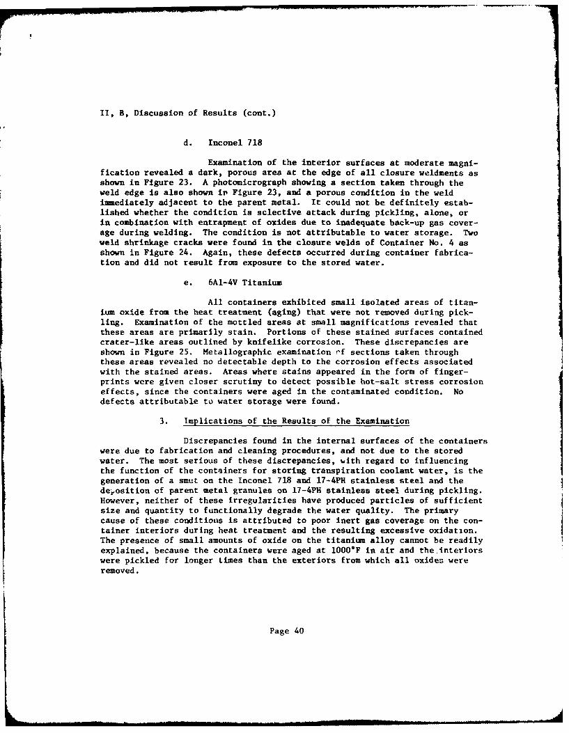
Examination of the interior surfaces at moderate magni-fication revealed a dark, porous area at the edge of all closure weldments asshown in Figure 23. A photomicrograph showing a section taken through theweld edge is also shown ir Figure 23, and a porous condition in the weldimmediately adjacent to the parent metal. It could not be definitely estab-lished whether the condition is sclective attack during pickling, alone, orin combination with entrapment of oxides due to inadequate back-up gas cover-age during welding. The condition is not attributable to water storage. Twoweld shrinkage cracks were found in the closure welds of Container No. 4 asshown in Figure 24. Again, these defects occurred during container fabrica-tion and did not result from exposure to the stored water.
e. 6AI-4V Titanium
All containers exhibited small isolated areas of titan-ium oxide from the heat treatment (aging) that were not removed during pick-ling. Examination of the mottled areas at small magnifications revealed thatthese areas are primarily stain. Portions of these stained surfaces containedcrater-like areas outlined by knifelike corrosion. These discrepancies areshown in Figure 25. Metallographic examination nf sections taken throughthese areas revealed no detectable depth to the corrosion effects associatedwith the stained areas. Areas where stains appeared in the form of finger-prints were given closer scrutiny to detect possible hot-salt stress corrosioneffects, since the containers were aged in the contaminated condition. Nodefects attributable to water storage were found.
3. Implications of the Results of the Examination
Discrepancies found in the internal surfaces of the containerswere due to fabrication and cleaning procedures, and not due to the storedwater. The most serious of these discrepancies, with regard to influencingthe function of the containers for storing transpiration coolant water, is thegeneration of a smut on the Inconel 718 and 17-4PH stainless steel and thedejosition of parent metal granules on 17-4PH stainless steel during pickling.However, neither of these irregularities have produced particles of sufficientsize and quantity to functionally degrade the water quality. The primarycause of these conditions is attributed to poor inert gas coverage on the con-tainer interiors during heat treatment and the resulting excessive oxidation.The presence of small amounts of oxide on the titanium alloy cannot be readilyexplained, because the containers were aged at 1000*F in air and the interiorswere pickled for longer times than the exteriors from which all oxides wereremoved.
Page 40
II, B, Discussion of Results (cont.)
The presence of contaminants in the titanium alloy containeis
prior to heat treatment and the weld cracks found in the A-286, Inconel 718,
and 17-4PH stainless steel containers are attributable to inadequate process
control on the part of the container supplier. In spite of the presence ofthe contaminants, the water quality was not significantly impaired.
All discrepancies found on the internal surfaces of the con-
tainers were due to fabrication and cleaning procedures and not due to thepresence of water in the containers.
I
PIIi
Page 41
SECTION III
CONCLUSIONS AND RECOMMENDATIONS
A. CONCLUSIONS
The following conclusions may be drawn from the twelve-month
storage evaluation program.
1. All five container materials, 304 and 17-4PH stainless
steels, A-286, Inconel 718, and 6A1-4V titanium, are suitable for the stor-age of water for transpiration cooling purposes.
2. Both the oxygen-free and oxygen-saturated waters demonstrated
favorable storability characteristics with regard to pH changes, ionic con-tamination as evidenced by electrical resistance measurements, and particu-late formation as evidenced by Silting Index values and microscopic inspec-tion of filters.
3. Based on the biological tests, there is no evidence thatbiological growth has occurred in the containers during storage periods upto twelve months.
4. Discrepancies in the containers such as cracks, smut and
etched surfaces were produced during fabrication, cleaning, and passivationof the containers. Yet with adequate flushing prior to storage, the storedwater is suitable for use as a transpiration coolant.
B. RECOMMENDATIONS
1. Long-term storage tests should be conducted with the selectedwaters in containers in which dissimilar metals are present to demonstratewhich combinations of metallic materials can be used as suitable componentsin a transpiration coolant system.
2. The ease of fabrication, cleaning, and passivation of con-
tainers should be given proper priority in the selection and design of con-tainer materials for transpiration coolant devices.
Page 42
FABRICATION AND TREATMENT PROCEDURES
FOR WATER CONTAINERS
The fabrication procedures, the heat treatment cycles, the cleaningprocedures, and the passivation procedures for the water containers prior tofilling are presented below.
A. CONTAINER FABRICATION
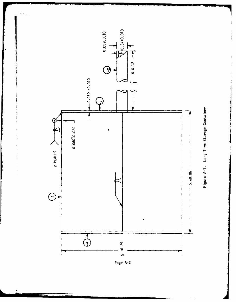
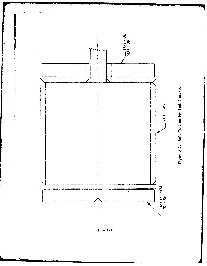
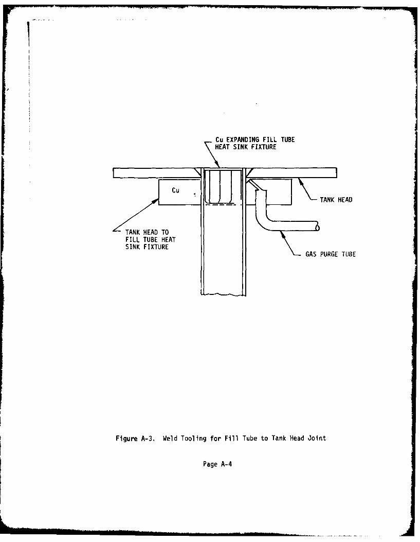
Drawings of the long term storage container and its asqociatedweld tooling are shown in Figures A-1, A-2, and A-3. The sequence of opera-tions in the container fabrication is as follows:
1. Cylindrical Tube, -1
a. Fabricate -1 cylinder tube by rolling the sheared sheetstock into the desired diameter.
b. Weld the longitudinal joint using the automatic CTA*welding process. Full weld penetration must be obtained using gas backupfor the welds.
c. Dye penetrant inspect welds then trim tubes to requiredlength. No cra-ks allowed.
d. Machine tube ends for weld joint preparation.
e. Clean tubes and store in appropriate container whileawaiting for next assembly.
2. Fill Tube, -2
a. Section fill tubes to 6 + 0.12 in. lengths.
b. Deburr fill tube ends and inspect.
c. Clean fill tubes and then package individually and
store for next assembly.
3. Tank Head, -3
a. Blank tank heads to the desired diameter by punching orsawing and then machining.
b. Machine weld joint preparation at outer edge asrequired.
c. Drill the fill tube hole to mate with the fill tube.
*Gas Tungsten Arc
Page A-I
9 0;
++1
40
+1
-W.
Co,
+1 4)C)4
V)0
LAJ
L)CD
-
e~LO
LL.
Ln
Page A-2
= 1nI---
INn
0
S-
I-
ZNJ
Page A-3
Cu EXPANDING FILL TUBEHET SINK FIXTURE
CuTNH TTANK HEAD
FILL TUBE HEATSINK FIXTURE
GAS PURGE TUBE
Figure A-3. Weld Tooling for Fill Tube to Tank Head Joint
Page A-4
9.: A, Container Fabrication (cont.)
d. Counter bore the tank head on one side at the fill tubehole for weld joint preparation.
e. Inspect tank heads, clean and package.
4. Tank End -4
a. Perform operations 3,a, 3,b, and 3,e as above.
5. Assembly Sequence
a. Assemble -2 fill tube into -3 tank head using appropri-ate weld fixture and tooling.
b. Weld root pass on grooves side without weld filler wireby the automatic GTA welding process.
c. Clean root pass by rotary wire brushing using a cleanstainless steel wire brush.
d. Weld the cover pass using the appropriate weld fillerwire.
e. Reposition the part in the weld fixture and then placea fillet weld at the fill tube to tank head junction.
f. Inspect welds and clean part.
g. Fixture tank head assembly with -1 tube for weldingand purge tank with Ar or He.
h. Weld root pass without the use of weld filler wire.Full penetration must be obtained at the ID of the joint.
Dye penetrant inspect and clean root pass. No cracksallowed.
j. Fill weld groove using the appropriate weld filler wire.
k. Inspect and clean the inner tank surfaces.
1. Locate the tank end to the tank for welding, then purgethe closed tank with Ar or He.
Page A-5
A, Container Fabrication (cont.)
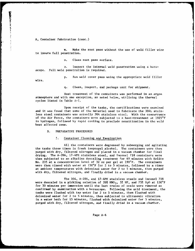
m. Make the root pass without the use of weld filler wireto insure full penetration.
n. Clean root pass surface.
a. Inspect the internal weld penetration using a bore-scope. Full weld penetration is required.
p. Run weld cover pass using the appropriate weld fillerwire.
q. Clean, inspect, and package unit for shipment.
Heat treatment of the containers was performed in an argonatmosphere and with one exception, as noted below, utilizing the thermalcycles listed in Table A-I.
Upon receipt of the tanks, the certifications were examinedand it was found that some of the material used to fabricate the 304L stain-less steel containers was actually 304 stainless steel. With the concurrenceof the Air Force, the containers were subjected to a heat-treatment at 1925 0Fin hydrogen, followed by rapid cooling to preclude sensitization in the weldheat affected zone.
B. PREPARATIVE PROCEDURES
1. Container Cleaning and Passivation
All the containers were degreased by submerging and agitatingthe tanks three times in fresh isopropyl alcohol. The containers were thenpurged with dry, filtered nitrogen and placed in a vacuum chamber for finaldrying. The A-286, 17-4P11 stainless steel, and Inconel 718 containers werethen subjected to an alkaline descaling treatment for 60 minutes with KeliteNo. 235 at a concentration level of 32 oz per gal at 190*F. The containerswere then rinsed with water at 150F for 2 to 5 minutes, followed by a rinseat ambient temperatures with deionized water for 2 to 5 minutes, then purgedwith dry, filtered nitrogen, and finally dried in a vacuum chamber.
The 304, A-286, and 17-4PH stainless steels and Inconel 718were descaled in a pickling solution of 20% HN03 , 5% HF, and 75% H20 at 130*Ffor 30 minutes per immersion until the last traces of scale were removed asconfirmed by examination with a borescope. Following the acid treatment, thetanks were flushed with tap water for 2 to 5 minutes, then flushed withdeionized water for 2 to 5 minutes, then subjected to ultrasonic vibrationin a water bath for 15 minutes, flushed with deionized water for 5 minutes,purged with dry, filtered nitrogen, and finally dried in a vacuum chamber.
Page A-6
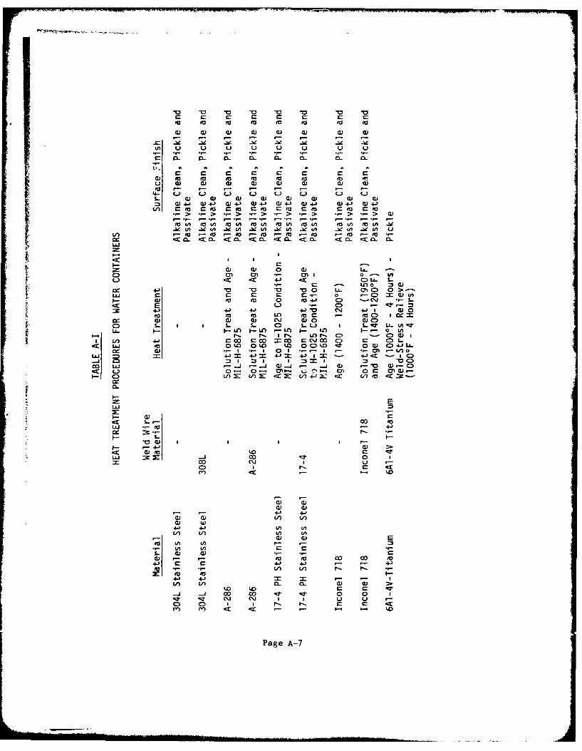
.o -o to eo to to AS to
4) 4) 4) 0) 0) 4) ) 0)
"- - - a- -l a- . C-
U.
a) m (a 0 0 0o 4) a) (D CU a) 0) 0) Q)
4- C..) C-.) u L) L i L J C) C-)1. ) a) a) Q) 0) 0) 0U a)
tof (A f (130 fg 0to(1 to/ 4A / to/ (1/.-Vu .ceu ~e cn -l n -e n 1C -e CA -!e V) e -b(A u
fA go t t 00 to0 0 -0 to
La.)
I S I
0) 0) M 0 La. UC- ~4-' C-) UL- 1.
CO 0 =) 0)4J-o -0 0 U. CN C) 0> -
LL) C - r C-- a C)0 (A)Ito go 0 0 o 041 C -. CJ --
E C-5 -a-.4-) - ~ 4-) wa C14 ~ I w 00
(D 0u 0) 0 Iv CC 0C) oi 5- CDJ 0)0 u 0)d0 L.
- LC) I- LO -. L I. L -) o CAL~nLa. r-Lf I-f .Il LO (~lC) I- CD 0)
I Ln .4-) a0 C02 rco CMc\1 CD C C &LL to. 0 0(0 0(0 0 00 - 00() Cl4 L.
0: 0) .- I .- I 0 .- - I - .- 0 .- V) 0
coJ +AJ -) _j _ 3_ - ( - IC):r L> 0- 0 m" L0In r W
Ca) V-) r-J Ul -X: CC2 J 0CC) to 0-CC
ui- - 0 ~ ~ . O~ O ))
I-Q
E
V- 0)
4J. -f0 - 4
00) V) I,* V
(n Ln- a-0) >.-
-a. co co --- 0 Icoi u -
Co I -C .
C)Page A-7
B, Preparative Procedures (cont.)
The 304 and A-286 stainless steels, and Inconel 718 werepassivated with a 30% HN03 /3% Na2Cr2O 7 aqueous solution at 130°F for 25 min-utes, rinsed with tap water for 2 to 5 minutes, rinsed with deionized waterfor 2 to 5 minutes, subjected to ultrasonic vibration in water for 5 minutes,rinsed with deionized water for 2 to 5 minutes, purged with dry, filterednitrogen, and dried in a vacuum chamber. The 17-4PH stainless steel receivedthe same treatment with the exception of a 10 minute passivation time.
The 6A1-4V titanium was degreased in isopropyl alcohol asdescribed previously for the other tankage and then descaled in a picklingsolution of 33.2% HN03 , 1.6% HF, and 65.2% water at 140°F for 3 minutes. Thetitanium containers were rinsed with 130°F tap water for 2 to 5 minutes, fol-lowed by a rinse in deionized water for 2 to 5 minutes, then subjected toultrasonic vibration in water for 5 minutes, rinsed with deionized water for2 to 5 minutes, purged with dry nitrogen, and then dried in a vacuum chamber.
2. Container Sterilization, Filling, and Sealing
Following the final rinsing with deionized water and the dry-ing of the container in a vacuum chamber, the containers were wrapped withreusable sterilization paper. The wrapped containers were then sterilized inan autoclave at 250°F with 15 psig steam for 30 minutes followed by a 30-minutedrying period. The containers were then stored in the paper to maintain theirsterile condition.
All the steps required to ftil the containers with water wereconducted in the bcerile laminar flow berch. The tanks were removed from thewrapping paper in the laminar flow bench. The tanks were weighed empty; thenweighed when filled completely with sterile water to determine the totalvolume of the tank. The water was drained out and the tank was rinsed oncemore with the sterile water. A sample of the rinse water was checked for pH,conductivity, and Silting Index. If the values indicated that particulatematter and dissolved species were not present, the tank was considered readyfor filling; if the values indicated that contaminants were present, the tankwas rinsed until there was no evidence of contamination.
Before the final filling with oxygen-saturated deionizedwater, the tank was purged with oxygen from a filtered supply. The tank wasthen filled with the water and a sample was withdrawn for pH, conductivity,and Silting Index measurements. The ullage was adjusted to the ten percentvalue by weighing the container and its contents; the ullage space was purgedwith the filtered oxygen; and the container was capped with a sterile,tapered plug made from the same material as the container. The plug wasseated in the fill-tube by use of a hammer. The containers were filled withthe oxygen-free, deionized water in an analogous manner except that filterednitrogen was used instead of oxygen for purging and blanketing the container.
Page A-8
1IB, Preparative Procedures (cont.)
The final sealing of the containers was accomplished by GTAwelding the fill-tube/plug interface. The welds were inspected visually forany apparent anomalies. None were found. Then the containers were placed inplastic bags and labeled for the long-term storage tests.
The sampling plan for the long-term storage tests is to
remove one container of each material with the two types of water for inspec-
tion and evaluation every six months for a period of five years. The contentswill be characterized with respect to pH, conductivity, particulate content,and biological activity; and the containers themselves will be subjected tometallurgical examination if the other test data indicate that this is
required.
P e
|t Page A-9
SILTING INDEX MEASUREMENT
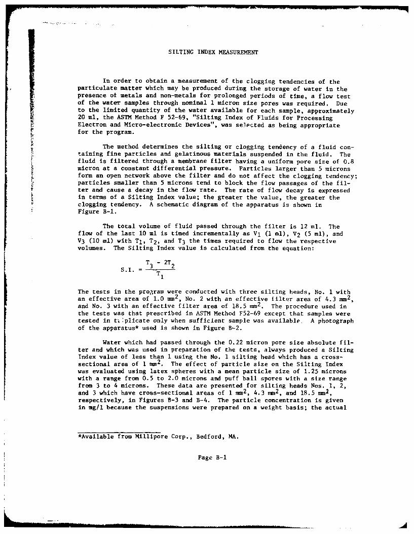
In order to obtain a measurement of the clogging tendencies of theparticulate matter which may be produced during the storage of water in thepresence of metals and non-metals for prolonged periods of time, a flow testof the water samples through nominal 1 micron size pores was required. Dueto the limited quantity of the water available for each sample, approximately20 ml, the ASTM Method F 52-69, "Silting Index of Fluids for ProcessingElectron and Micro-electronic Devices", was selected as being appropriatefor the program.
The method determines the silting or clogging tendency of a fluid con-taining fine particles and gelatinous materials suspended in the fluid. Thefluid is filtered through a membrane filter having a uniform pore size of 0.8micron at a constant differential pressure. Particles larger than 5 micronsform an open network above the filter and do not affect the clogging tendency;particles smaller than 5 microns tend to block the flow passages of the fil-
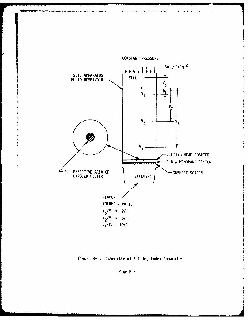
rter and cause a decay in the flow rate. The rate of flow decay is expressedin terms of a Silting Index value; the greater the value, the greater theclogging tendency. A schematic diagram of the apparatus is shown inFigure B-I.
The total volume of fluid passed through the filter is 12 ml. Theflow of the last 10 ml is timed incrementally as V1 (I ml), V2 (5 ml), andV3 (10 ml) with TI, T2 , and T3 the times required to flow the respectivevolumes. The Silting Index value is calculated from the equation:
T3 - 2T 2
TI
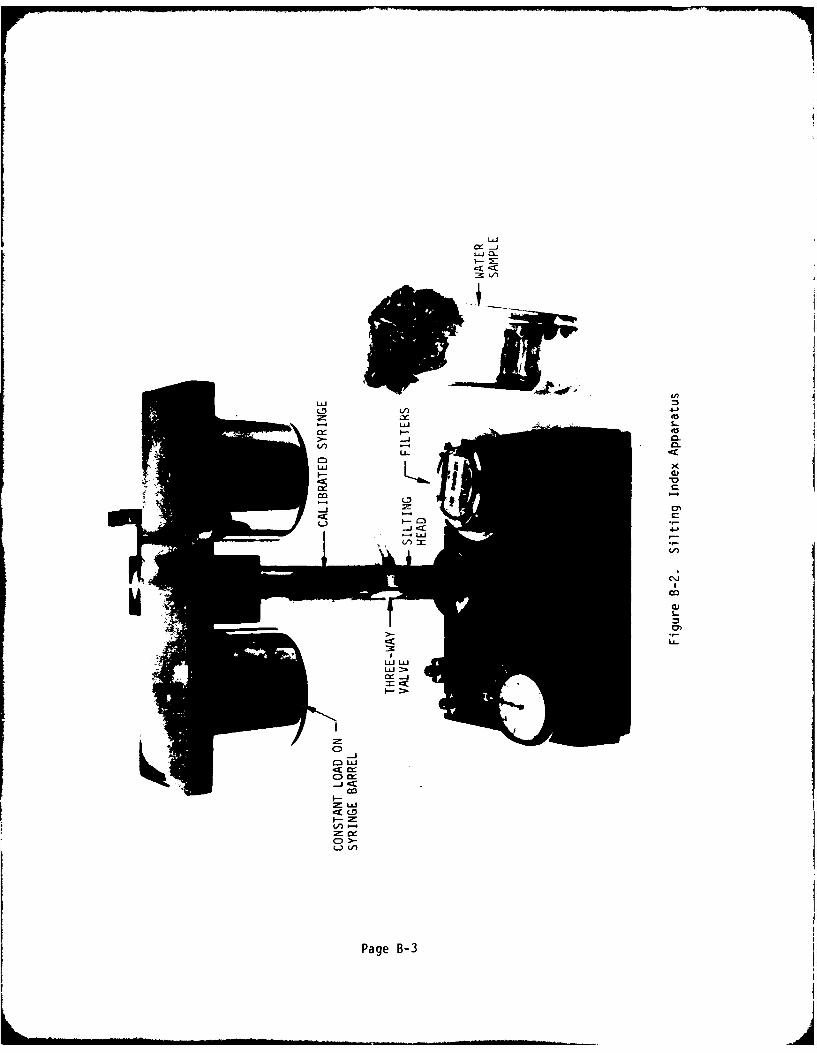
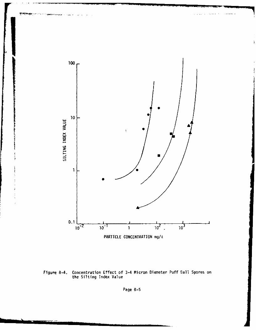
The tests in the program were conducted with three silting heads, No. 1 withan effective area of 1.0 mm2 , No. 2 with an effective filter area of 4.3 mm2 ,and No. 3 with an effective filter area of 18.5 m2. The procedure used inthe tests was that prescribed in ASTM Method F52-69 except that samples weretested in ti.plicate only when sufficient sample was available. A photographof the apparatus* used is shown in Figure B-2.
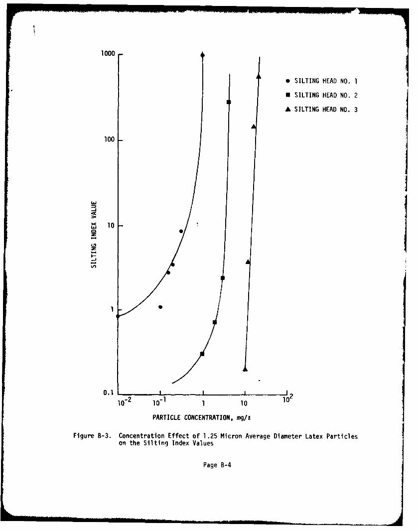
Water which had passed through the 0.22 micron pore size absolute fil-ter and which was used in preparation of the tests, always produced a SiltingIndex value of less than I using the No. 1 silting head which has a cross-sectional area of I mm2 . The effect of particle size on the Silting Indexwas evaluated using latex spheres with a mean particle size of 1.25 micronswith a range from 0.5 to 2.0 microns and puff ball spores with a size rangefrom 3 to 4 microns. These data are presented for silting heads Nos. 1, 2,and 3 which have cross-sectional areas of 1 mm2, 4.3 mm2, and 18.5 mm2,respectively, in Figures B-3 and B-4. The particle concentration is givenin mg/l because the suspensions were prepared on a weight basis; the actual
*Available from Millipore Corp., Bedford, MA.
Page B-i
------ ......... ..... , .. ...... . . ... ..! .. .... ..
CONSTANT PRESSURE
50 LBS/IN.2
S.I. APPARATUSFLUID RESERVOIR FILL
VVl¥, 1
V 2V2 2 V3
V V3
~~S I LTING HEAD ADAPTER
- -- 5W O.8 MEMBRANE FILTER
A EFFECTIVE AREA OF SUPPORT SCREENEXPOSED FILTER EFFLUENT
BEAKER
VOLUME - RATIO
V /V = 2/
V/V= 5/1
V3 /V1 = 10/1
Figure B-1. Schematic of Silting Index Apparatus
Page B-2
bLJ
L~L.J
L)D
L-33
V)
L.
0>-(-)C
Paeo -
1000
* SILTING HEAD NO. 1
E SILTING HEAD NO. 2
A SILTING HEAD NO. 3
100
10
0.1 I 2
10- 2 10- 1 1 10 10'
PARTICLE CONCENTRATION, mg/i
Figure B-3. Concentration Effect of 1.25 Micron Average Diameter Latex Particleson the Silting Index Values
Page B-4
100
L&10
LUS
Li,
0.1 L I I
10- 2O 101 1 2 1
PARTICLE CONCENTRATION mg/k
Figure B-4. Concentration Effect of 3-4 Micron Diameter Puff Ball Spores onthe Silting Index Value
Page B-5
densities of the particles are comparable. The significant item to note fromthe comparison of the data is that the Silting Index values are comparable atconcentration levels that differ by at least one order of magnitude, thesmaller particle producing the higher Silting Index value.
Page B-6