Embed Size (px)
Citation preview

AD-755 108
DESIGN AND INITIAL OPERATION OF A 3-DEGREEOF FREEDOM MAGNUS ROTOR IN A MAGNETICBALANCE SYSTEM
James B. Coffin, et al
Massachusetts Institute of Technology
Prepared for:
Picatinny Arsenal
January 1973
DISTRIBUTED BY:
National Technical Infomaion ServiceU. S. DEPARTMENT OF COMMERCE5285 Port Royal Road, Springfield Va. 22151
COPY H0.LI3 -
TECHNICAL MEMORANDUM 2069
DESIGN AND INITIAL OPERATION
OF A
3. DEGREE OF FREEDOM MAGNUS ROTOR
IN A
MAGNETIC BALANCE SYSTEM
.BY
VJAMES S. COFFNCHARLES W. HALDEM! 1FL D8997
JANUARY 1973
TIS DOCUMENT HAS BEEN APPROVED FOR PUBLIC RELEASE ANDSALE; ITS DISTRIBUTION IS UNLIMVIED.
NATIONAL TECHNICALINFORMATION SERVICE
IS cco" C> ' r.a
PICATINNY ARSENAL
DOVER. NEW JERSEY

Ile findings in this report ame not to be construedas an officia DepTartmnent of the Army position ualeasso designated by offier authoized documents.
DISPOSITON
Dint=,, this report when Do longer needed. Do uotreturn it to the orignt~or.

-P -- 7 '4-
,UNCLASSIFIEDSecurity classificaetion
DOCUMENT CONTROL DATA.- R & D(Security claificat ion of title, body of absa land lndeelnd onnotation must be entered when the overall vepott is classified)
I ORIGINATING ACTWIVTY (CoItIor.te autho0r) 2a NEPORT SECURITrY CLASSIFICATION
Massachusetts Institute of Technology Unclas sifiedDepartmnent of Aeronautics and Astronautics 2b. GROUP
Cambridee Massachusetts3 REPORT TITLE
DESIGN AND INITIAL OPERATION OF A 3-DEGREE OF FREEDOM MAGNUS ROTOR INA MAGNETIC BALANCE SYSTEM
4. DESCRIPTIVyE NOTES (Type of tepoet and Incilusive dotes)None_________________ _
t. AUTI4ORISI (Fifltname, middle initial, tee. neat.)
James B. CoffinCharles W. Haldeman
S. REPORT DATE M8. TOTAL NO. OF PAGES 7b. No OF ReFs
January 1973 .2'11sa CNRAT RGRANT NO. e ORIGINATOR'$ REPORT NUMBERIS1
DAA~l-2-C-0254b. PROJECT NO. None
C. Ob. OTHER REPORT NOISI (Any other num~bers et ait be assignedtis report)
PA TMI 2069t0. OISTRIOUTSON STATEMENT
Approved for Public Release; Distribution Unlimnited
11. SUPPLEMENTARPY NOTES 12 SPONSORING MILITARY AC rIVITy
None U.S.Army Munitions CommandNone IPicatinny Arsenal____________________________ Dover,_NewJersey_07801
IS. AGISTRACT
Progress i reported on an experimental program to determine the Magnusforces on the center of gravity and the rotational startup responseof a self-spinning rotor in a subsonic air stream. Development of a newtype of model for the magnetic balance system was required in order toprovide rotational freedom about all three axes. The design, construc-tion and initial testing of this model at low subsonic speeds are dis-cusscd. The resulLs indicate that model~s with three degrees of rotation-al freedom can be 'guspended with the magnetic balance system and testedin a subsonic air stream. Because of the force limits of the presentbalance system, the maximum operating dynamic pressure for this model islow.
DD I n.,*1473 :LI O .wleS ANS.WHC
KL
IPW
UNCLASSIFIED5.city Classification
.KYWOD LINK A LIK a LINK C_____________________________________ OLE WY ROLE WT ROL1.E WT
FMagnus rotors
Magnetic Balance
UNCLASSIEIE:Dsecuity Classification

PICATINNY ARSENAL TECHNICAL MEMO 2069
DESIGN AND INITIAL OPERATION OF A 3-DEGREE
OF FREEDOM MAGNUS ROTOR IN A MAGNETIC BALANCE SYSTEM
January 1973
By
James B. Coffin
and
Charles W. Haldeman
Conducted for
Feltman Research Laboratories
Picatinny Arsenal
Dover, New Jersey
Under
Contract No. DAAA21-72-C-0254
By
Massachusetts Institute of Technology
Department of Aeronautics and Astronautics
Aerospace Research Division
Aerophysics Laboratory
Cambridga, Massachusetts 02139
!e

low 1W
TABLE OF CONTENTS
Title Page No.
Foreword iii
Abstract iv
Introduction 1
Discussion 1
Model Design 1
Wind Tunnel Tests 4
Conclusions 7
References 8
Figures 10
Distribution List 17
ii

FOREWORD
This work was performed at the AerophysicsLaboratory, Massachusetts Institute of Technology,Cambridge, Massachusetts 02139. The work wassponsored by the U. S. Army Munitions Command,Picatinny Arsenal, Dover, New Jersey 07801 underContract DAAA21-72-C-0254. This contract wasmonitored by Mr. Alfred Loeb, Chief, AeroballisticsBranch, Picatinny Arsenal, Dover, New Jersey. Over-all supervision of this study was provided byProfessor Eugene E. Covert, of the M. I. T. Aero-physics Laboratory, in the capacity of PrincipalInvestigator. This report covers work performedduring the period February 7, 1972 to August 31,1972.
The authors would like to thank the NASALangley Research Center for the use of the magneticbalance equipment.
iii
K

ABSTRACT
Progress is reported on an experimental pro-gram to determine the Magnus forces on the centerof gravity and the rotational startup response ofa self-spinning rotor in a subsonic air stream.Development of a new type of model for the magneticbalance system was required in order to providerotational freedom about all three axes. The design,construction and initial testing of this model atlow subsonic speeds are discussed. The resultsindicate that models with three degrees of rotationalfreedom can be suspended with the magnetic balancesystem and tested in a subsonic air stream. Becauseof the force limits of the present balance system,the maximum operating dynamic pressure for thismodel is low.
iv

INTRODUCTION
Magnus forces have long been important to theflight dynamics of specializedmunitions. To date,experimental information has been obtained on theseconfigurations by both wind tunnel (1-4) and freeflight tests. The wind tunnel tests, of necessity,have utilized stings or yokes of some sort to sup-port the model. These physical model supports havematerially interfered with the aerodynamics beingstudied thus compromising to some extent comparisonsbetween wind tunnel and free drop test. The freedrops provided only general performance informationbecause of the nature of the configurations.
This report* describes the design, constructionand initial testing of a free spinning Magnus rotorunder startup conditions in a magnetic suspension andbalance system (5-9). Figure 1 shows the subsonicwind tunnel and magnetic balance system. Figure 2shows a rotor model magnetically suspended in theopened test section.
DISCUSSION
Model Design
The primary objective of this model design is to
provide complete angular freedom about three axes
while maintaining the maximum possible volume for the
iron core. Two possible configurations were consi-
* Some of the material in this report was presentedat the AIAA 2nd Atmospheric Flight Mechanics Con-ference (10).
1
L,

dered. The first - a precision ball bearing surroundad
by small friction pads of teflon or pyrolytic graphite -
provided the greatest usable volume of core material.
The level of the friction force, however, could not be
accurately predicted and it was therefore not developed
in favor of the second jewel bearing configuration.
This model configuration consists of five parts
shown in Figures 3 - 6. Complete assembly is shown
in Figure 7. This model is designed to simulate the
dynamics of a free spinning body under startup conditions
and to provide force measurements during the steady
phase of the motion.
In order to be able to hold the model properly
with the magnetic balance and obtain the desired data,
all parts of the model should be made of nonmagnetic,
non-conducting materials except the magnetic core
material that is being held. The outer shell (Fig. 3) is
made from a Textolite sleeve with the aerodynamic shape
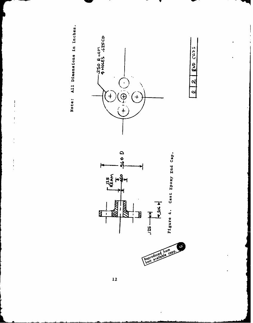
cast onto it with epoxy*. The two end caps (Fig. 4) are
macbined to shape from cast epoxy. The cage (Fig. 5) is
wound from fiber glass filament that is impregnated with
epoxy. It is then cast to shape on a Wood's metal mandrel
which is later removed by melting. The magnetic core
is shown in Figure 6. It is machined from Armco ingot
iron. The assembly drawing of the model is shown in
Figure 7.
* Stycast 3050, manufactured by Emerson and Cuming,
Inc., Canton, Massachusetts.
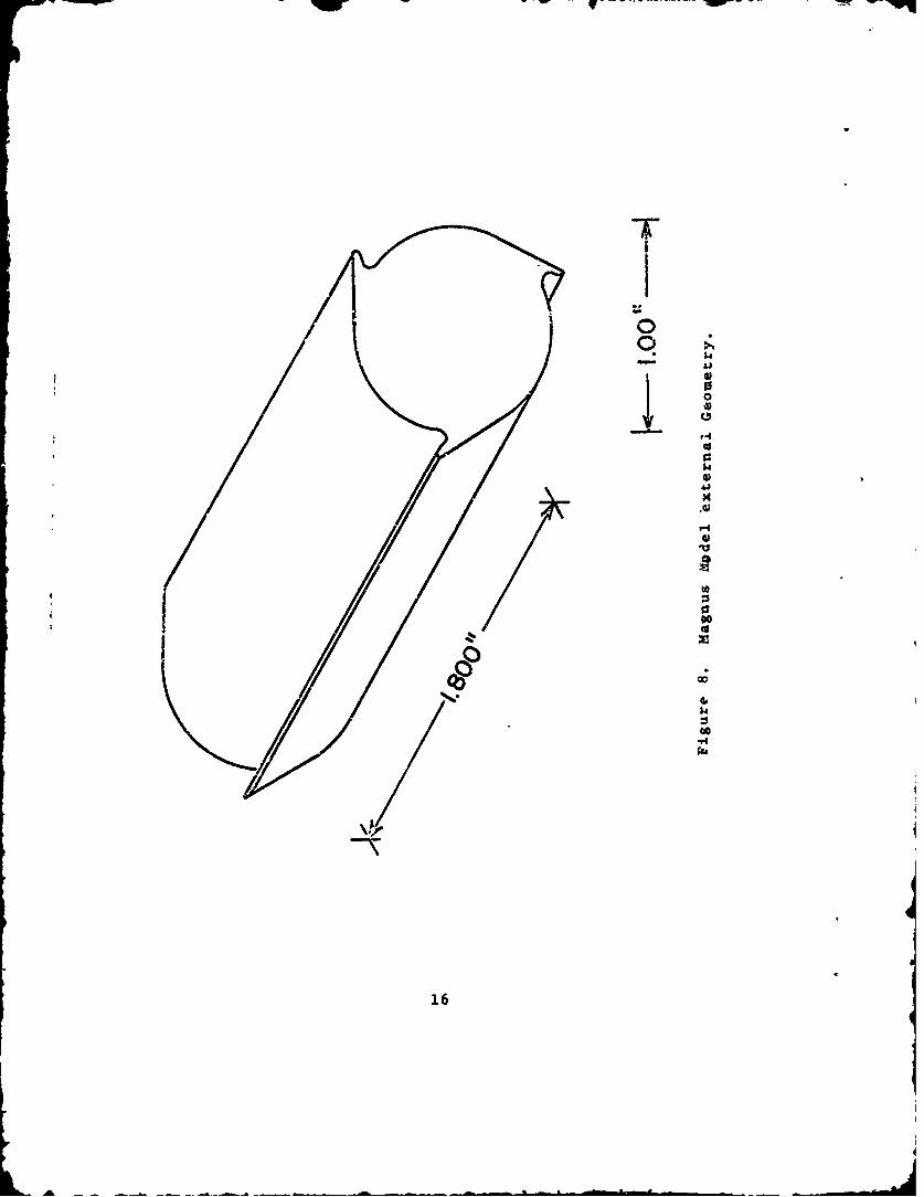
This model can be held in the magnetic suspension
system and will. be free to rotate about three axes.
The external aerodynamic shell of the shape shown in
Figure 8 is freely pivoted about the gymbal cage with
jewel bearings*. This cage is in turn pivoted about the
iron core with a second set of jewel bearings (Figure
7). The third degree of rotational freedom is derived
from the intrinsic character of the magnetic model which
is free to rotate about the principal axis of the
magnetic field. This forms the third axis of the gymbal
system. As the magnetic core can rotate only about
this axis, which remains fixed in space, the combination
provides complete freedom of angular motion. Since the
position of the core is maintained by the electro-
magnetic position sensing system (7), all parts of the
model except the core must be nonmagnetic, and to the
greatest extent possible non-conducting.
In crder to obtain angular position and rotational
speeds, the model can be painted so that the various
positions can be distinguished. To reduce frame-by-
frame positions to velocities, accurate timing marks
should be superimposed on the film.
* Each bearing consists of a hard metal tapered pivotwhich runs against a similarly tapered hole in an alu-minum oxide jewel. The jewel is pressed into an adjust-ing screw. By properly adjusting the relative positionof the jewels and pivots, both radial and axial loadscan be supported by a single pair of bearings (2 jewelsand 2 pivots).
3

I-PW I -F
WIND TUNNEL TESTS
Initial Wind Tunnel Testing
The subsonic wind tunnel used is described in Ref-
erence 11 and Figure 1. The t'innel aerodynamic config-
uration, however, departed slightly from normal since a
450 mirror was installed in the diffuser the wind
tunnel so that the Magnus rotor could be observed and
photographed.
The testing of the model consisted of hanging the
model in the suspension system (an operation which re-
quires higher power than most other models) and then
simultaneously starting the wind tunnel and exposing the
roll of movie film. The camera used was a Fastax Model
WF-3 operating at 1,000 frames per second which is the
minimum framing rate of this camera. It should be noted
that this camera holds 100 foot rolls of film. This
means that the maximum observation time with a roll of
film is approximately 4.5 seconds.
The model was tested and several rolls of film were
taken with the wind velocity at 45 feet per second.
The results of the initial wind tunnel operations
indicated that the model was subject to a small torque
applied to it by the magnetic fi i, and this kept the
model oriented with its axis parallel to the wind tunnel
axis, with the wind off. A check of the model parts
showed that the brass jewel holders and the brass jewel
screws were very slightly magnetic. This produced a
slight torque tending to align the long axis of the rotor
with the magnetic field and vaused the observed steady
precession of the spinning model. To correct this prob-
lem some new jewel screws and jewel holders were ordered
4
0'0

in beryllium copper which is nonmagnetic. (The brass was
magnetic because of a permitted iron content of up to 1%.)The brass jewels were ordered first becau3e they were
a stock item and it was not known that the brass used had
a small iron content.
Force limits on the model.
It should be pointed out that a model of this type
is very hard to hold in this present balance system since
the system is underpowered. This particular model has a
very small magnetic volume compared to its aerodynamic
cross section and therefore requires a very strong mag-
netizing current, in the order of 200 amps., and a high
pressure water system to keep the magnetizing windings
cool.
Second Series of Tests
A second series of tests was scheduled to cbtain
more movies of the Magnus rotor with the new beryllium
copper jewel screws and jewel holders. Before the tests
the beryllium copper jewel screws and jewel holders were
tested in a magnetic field to make sure that they showedno signs of being magnetic. The tests showed that they
were indeed nonmagnetic.
In the process of setting up the magnetic balance
to hold the model certain irregularities were noticed inthe operation of the balance system. The problem was
traced to the downstream Helmholtz coil. This coil after
examination proved to have a short between two adjacent
layers. The two Helmholtz coi2s provide a uniform mag-
netizing field for the model. However, with this short
in the downstream coil the field was not uniform. To
make the fields uniform again, a shorting bar was placed
5

on the same windings of the upstream coil. After this
was done the fields were checked and found to be uniform
again. However, further testing on this model, at high
power, was suspended for fear of further and more serious
damage to the set of coils. It appears that some damage
to the high pressure water system in the past partially
blocked some tubes in the coil and caused local overheat-ing which resulted in the present damage. Operation with
models of larger magnetic volumes can be continued as
they requirB much less magnetizing current to hold the
model. However, repair of the magnetic balance by repla-
cing the defective coils will be required before further
work on the Magnus rotor can be performed.
Due to the damage to the coil no further films were
obtained on the Magnus rotor model.
6
L,

CONCLUSIONS
This program demonstrates that testing with the
magnetic suspension system is feasible for this model
and other unusual aerodynamic shapes, when it is desired
to observe their complicated mctions under wind tunnel
conditions.
In the design of a model of this type, to be used
in a magnetic suspension system, it is very important
that there be absolutely no magnetic material in the
model except for the core. Any magnetic material other
than the core provides torques on the aerodynamic shell
that distort the true model motion.
A 16 mm, 1,000 frame-per-second motion picture film
showing the motion of the rotor was obtained by photo-
graphing the model image in a mirror located in the
diffuser section of the subsonic wind tunnel.
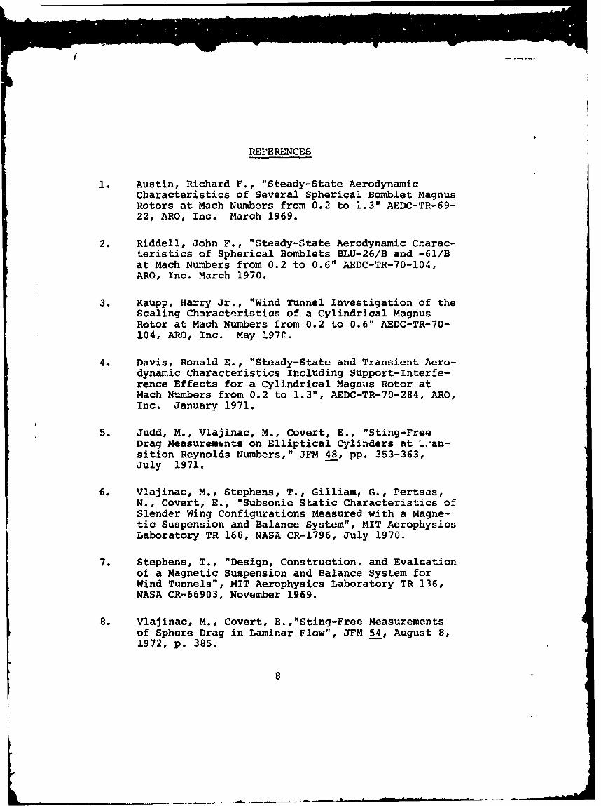
REFERENCES
1. Austin, Richard F., "Steady-State AerodynamicCharacteristics of Several Spherical Bomblet MagnusRotors at Mach Numbers from 0.2 to 1.3" AEDC-TR-69-22, ARO, Inc. March 1969.
2. Riddell, John F., "Steady-State Aerodynamic Cr.arac-teristics of Spherical Bomblets BLU-26/B and -61/Bat Mach Numbers from 0.2 to 0.6" AEDC-TR-70-104,ARO, Inc. March 1970.
3. Kaupp, Harry Jr., "Wind Tunnel Investigation of theScaling Characteristics of a Cylindrical MagnusRotor at Mach Numbers from 0.2 to 0.6" AEDC-TR-70-104, ARO, Inc. May 197C.
4. Davis, Ronald E., "Steady-State and Transient Aero-dynamic Characteristics Including Support-Interfe-rence Effects for a Cylindrical Magnus Rotor atMach Numbers from 0.2 to 1.3", AEDC-TR-70-284, ARO,Inc. January 1971.
5. Judd, M., Vlajinac, M., Covert, E., "Sting-FreeDrag Measurements on Elliptical Cylinders at 'an-sition Reynolds Numbers," JFM 48, pp. 353-363,July 1971.
6. Vlajinac, M., Stephens, T., Gilliam, G., Pertsas,N., Covert, E., "Subsonic Static Characteristics ofSlender Wing Configurations Measured with a Magne-tic Suspension and Balance System", MIT AerophysicsLaboratory TR 168, NASA CR-1796, July 1970.
7. Stephens, T., "Design, Construction, and Evaluationof a Magnetic Suspension and Balance System forWind Tunnels", MIT Aerophysics Laboratory TR 136,NASA CR-66903, November 1969.
8. Vlajinac, M., Covert, E.,"Sting-Free Measurementsof Sphere Drag in Laminar Flow", JFM 54, August 8,1972, p. 385.
8

REFERENCES -continued
9. Stephens, T., Covert, E. E., Vlajinac, M., Gilliam,G., "Racent Developments ia a Wind Tunnel MagneticBalance", AIAA Paper No. 72-164, January 1972.
10. Coffin, J. and Haldeman, C., "Dynamics of a FreeSpinning Magnus Rotor Under Startup", paper pre-sented at the 2nd AIAA Atmospheric Flight MechanicsConference at Palo Alto, California, September 11-13, 1972.
11. Vlajinac, M., "Design, Construction and Evaluationof a Subsonic Wind Tunnel", Massachusetts Instituteof Technology, Department of Aeronautics and Astro-nauti.-s, M. S. thesis, June 1970.
9
.
L.

'RP
Fig. 1. The Subsonic Tunnel and MagneticBalance Assembly.
rFl~. 2. Rotor M~odel .lagncotically Suspended in')puned Subsonic icst Section.
10

lw - --
4r
-- aw
$4
.r44*e
- w --- U- -- w
0
o
0r'4
.5.4
S I (
0 I C,

IF
N ,,N
00
v.4A
0 0
a 0 %3
V-4
0 0
0 0 44
0 0 0
Oo
13

0
0
00
UU
, -
K N.
14 )
0ezo
i/

00
~~II
* -o
CL
4C(4
*c 0
i5
00
60
16)