Embed Size (px)
Citation preview
AD-751 891
HAZARDS ASSOCIATED WITH THE OPERATION OFMICROWAVE OVENS
James D. Wallace
Environmental Health LaboratoryMcClellan Air Force Base, California
March 1969
DISTRIBUTED BY:
National Technical'Information ServiceU. S. DEPARTFMENT Of COMMERCE5285 Port Royal Road, Springfield Va., 22151
Report No. 69M-6(Project No. E68-57)
RI N
1- : ,
HAZARDS ASSrCIATED WITH THENet OPERATION OF MICROWAVE OVENS a
James D. Wallace, Captain, USAF, BSC
March 1969DDC
Details of Illustrations Inthis document may be better 31
studied on microfiche
B
Reprodu cd by
NATIONAL TECHNICAL DISTBUTION STAT AINFORMATION SERVICE Approved for public relozm
U S Department of Conmerce
Sr-gfiefd VA 22)51 D)istribution Unlimited
U S A F ENVIRONMENTAL HEALTH LABORATORY
McCLELLAN AFB, CA. 95652AFLC 8MAMA APR 691 3H-1
Uac].asg,ifiedSecurity Classification
DOCUMENT CONTROL DATA - R & D(Security clax3sification of title, body of abstract and indexing annotation must be entered when the overall report Is classified)
1. ORIGINATING ACTIVITY (Corporate author) 528. REPORT SECURITY CLASSIFICATION
I UnclassifiedUS'y PEiIRONIOENTAL HEALTH LAT.^ 700'o:7 2b. GROUP
UcCLELLAN AFB, CA. 956: I I3. REPORT TITLE
HAZARDS ASSOCIATED WITH THE OPERATION OF MICROWAVE OVENS
4. DESCRIPTIVE NOTES (2ype of raort and inclusive dates)
FINALS. AUTHORIS) (First name, middle initial, last name)
JAMES D. WALLACE
6. REPORT DATF 7a. TOTAL NO. OF PAGES 17b. NO. OF REFS
March 1969 31[ 24as. CONTRACT OR GRANT NO. 9a. ORIGINATOR'S REPORT NUMBERIS)
b. PROJECT NO. 69M-6
C. 9b. OTHER REPORT NO(S} (Any other numbers that may be assignedthis report)
d.
10. DISTRIBUTION STATEMENT
Distribution of this document is unlimited
It. SUPPLEMENTARY NOTES r12. SPONSORING MILITARY ACTIVITYDetails ot illustrations in[ USAF Environmental H.l; ~
this document may be better NICCelf FB, CA S5652studied on mir'ofiche ...... C...
'3. AaST/•C ~review of the literature ef--IHaza-rds associated with the Operation of
Microwave Ovense was undertaken along with a physical survey of microwave ovensbeing operated at USAF bases. The operation of an oven with (1) interlocks thathave been "jumped" (overridden) or have failed (2) door partially or fully openrepresents the most serious hazard to operating personnel of these ovens, anevaluation of this situation was performed in the laboratory. Purpose of these stud-ies was to appropriate survey procedures and equipment, and provide guidance forinterpretation of survey results.
It was concluded that there is very little hazard associated with the normaloperation of these ovens, even though some leakage may occur. Periodic surveys ofthese ovens are necessary to determine if interlocks have failed or have been'jumped" (overridden), and if significant leakage is occuring. Recommendationsare made for survey procedures and equipment to be used. Levels of microwaveradiation leakage which require corrective action are presented.
!Il-V
D FOR 17D Nov e51 S 7 TUnclassified -
tr~t% Class tfi. dttzn
Security Classification
14. LINK A LINK a LINK CKEY WOROS -...-.-.SROLE WT ROLE WT ROLE WT
MICROWAVE OVENSHAZARDSMICROWAVE SURVEYSRADIATION
, ncurity Clljsification
&
USAF ENVIRONMENTAL HEALTH LABORATORYMhClellan Air Force Base, California
HAZARDS ASSOCIATED WITH THEOPERATION OF MICROWAVE OVENS
Report No. 69M-6(Project No. E68-57)
March 1969
Prepared by:
JAMES D. WALLACECaptain, USAF, BSCChief, Special Projects D'ivision
Approved by:
FRANCIS S. SMITHColonel, USAF, BSCCommander
[T

ABSTRACT
A review of the literature , "Hazards Associated with the opera-
tion of Microwave Ovens" was undertaken along with a physical surveyof microwave ovens being operated at'USAF bases. The operation ofan oven with (1) interlocks that have been "jumped" (overridden) orhave failed (2) door partially or full open represents the most serioushazard to operatirt personnel of these ovens, an evaluation of thissituation was performed in the laboratory. Purpose of these studieswas to evaluate the magnitude of the hazad involved, recommendappropriate survey procedures and equipmnent, and provide guidancefor interpretation of survey results.
It was concludtd that there is very little hazard associated withthe normal operation of these ovens, even though some leakage mayoccur. Periodic surveys of these overs are necessary to determineif interlocks have ;ailed or have been "jumped" (overridden), and ifsignificant leakage is occurring. Recommendations are made forsurvey procedures and equipment to b( used. Le-els of microwaveradiation leakage which require corrective action are presented.
i cL
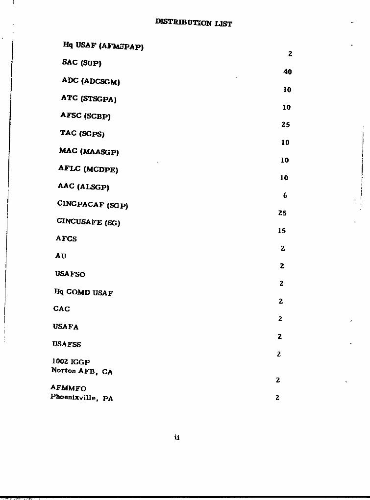
DISTREBUTION LIST
Hq USAF (AFUS-PAp)2
SAC (SUP) 40
10
ACIPAA (SSGP) 2
CINC US AFE (S) 15
A 25
CAC 2Sps
1002 I10Noron FBCApE
25AFMM SFO
2SG
iis

To6BLE OF CONTENTS
SECTION PAGE
I Introduction and Purpose 1
II Review of Literature and Discussion 1
III Scope of Survey 13
IV Survey Results 13
V Discussions of Results an,2 Conclusions 16
VI R €commendations 17
Bibliography 19
LIST OF TABLES
TABLE
Ia Summary of Released Microwave Intensities 6
Ib Summary of Released Intensities - All UnitsMonitored 6
II Summary of Released Microwave IntensitiesDenver Area 7
III Summary of Released Microwave Intensities 7
IVa Microwave Intensities Emitted from ClosedOvens 8
lVb Summary of Released Radiation Intensities of
Monitored Ovens 9
V Microwave Leakages Associated with theOperation of Various Microwave Ovens 10
VI Summary of Surveys by US Army 1.
VII Summary of Results of Survc.ys at AFInstallations 14
iii
TABLE OF CONTENTS (CONT'D)
VIII Microwave Field From an Oven, Door Open 14
FIGURE I Location of Survey Points 15
APPENDICES
APPENDIX
.Ltr, Hq USAF (AFSPAP) to All Cor-mands,11 July 68, Subject: Mico-owavF Oiens
II Ltr, Hq AFLC (MCDPE) to All AFLC Bases,16 July 68, Subject: Microwave Ovens
III Survey Equipment and Description
Empire Power Density Meter, Model NF-157
Probes, Model NF-157, Power Density Meter
Ramcor Power Density Meter
Microlite (Probe) 287
Fluorescent Bulb
IV Survey Procedures
iv
SECTION I
INTRODUCTION AND PURPOSE
In letter from Hq USAF (AFMSPAP) to all commands, dated 11 July1968, subject; "Microwave Ovens" (See Appendix. I), it was pointed outthat certain reports have indicated that excessive amounts of microwaveradiation may be emitted from microwave ovens. TI-ese reports indi-cate that this situation is brought about by malfunctioning interlockswitches, poorly installed seals, or misaligned doors.
Commands were requested to forward consolidated listings of basesno*. laving the capability to survey these ovens to Hq AFLC (MCD1?E).AFLC then was to arrange for the survey of these ovens (See Appendix llj.
Field guidance is needed as to appropriate survey equipment, pro-cedures, and periodicity of surveys. The magnitude of the hazardassociated with the operation of microwave ovens at USAF bases needsto be defined so the above guidance could be given. It is the purpose ofthis study to fulfill these requirements.
SECTION 11
REVIEW OF LITERATURE AND DISCUSSION
A. Near and far-field Regions: Microwave radiations fall within thespectrum of electromagnetic radiation. Generally they encompass therange of frequencies of from 300 to 3 x 10 s megahertz (MHz), wave-lengths of 1. 0 meter and 0. 1 cm respectively. The UHF, SHF, and EHFbands of the Hertzian or radio frequencies are contained in this range.These frequencies include radio, television, and commercial and militaryradar bands. Also, frequencies designated for medical diathermy treat-ment and those used in microwave ovens are in this range.
1. Near-field: In close proximity to the radiator or source of radi-ation such as an area of leakage from a microwave oven, a near fieldregion exists which is similar to fresnel region (See T.O. 31Z-10-4 fordescription, Ref 1). In a paper entitl-d "Near Field Radiated EmissionCharacteristics" the following observation was made:
"The near-field and far-field regions for an antenna or radiating4 element are difficult to define because there are no discrete dividing
lines between the regions. The definition is further complicated by thefact that different criteria are used to define the dividing line betweenthe regions. In one case, the dividing line ifs based on the ratio between
I-_
"induction" or "reactive" energy and propagated energy, in anothercase the dividing line is based on the degree of phase shift in thewave front, and in still another case, the dividing line is based onthe degree of amplitude variation in the wave front. While each ofthese criteria has some significance in terms of measurementaccuracy, the criteria do not, in the general case, establish aunique dividing line between the near-field and the far-field regionsof an electromagnetic radiator" (Ref 20).
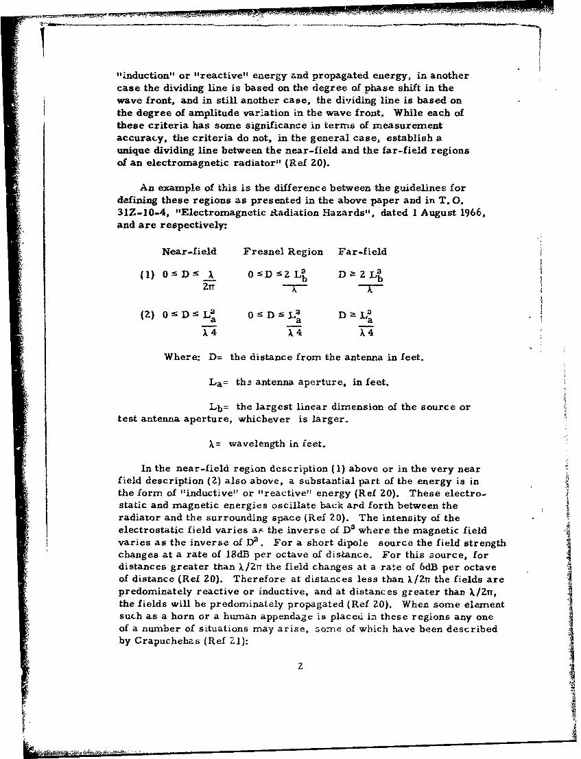
An example of this is the difference between the guidelines fordefining these regions as presented in the above paper and in T. 0.31Z-10-4, "Electromagnetic Radiation Hazards", dated 1 August 1966,and are respectively:
Near-field Fresnel Region Far-field
(2)~: 02~L 2 2~(1) 0 :5 D• :55 X 0sD• D aLa Lb
a a aX 4 X 4 X,4
Where: D= the distance from the antenna in feet.
La= th3 antenna aperture, in feet.
Lb= the largest linear dimension of the source ortest antenna aperture, whichever is larger.
X= wavelength in ieet.
In the near-field region description (1) above or in the very nearfield description (2) also above, a substantial part of the energy is inthe form of "inductive" or "reactive" energy (Ref Z0). These electro-static and magnetic energies oscillate back ard forth between theradiator and the surrounding space (Ref 20). The intensity of theelectrostatic field varies a., the inverse of D3 where the magnetic fieldvaries as the inverse of D2 . For a short dipole source the field strengthchanges at a rate of 18dB per octave of distance. For this source, fordistances greater than X/2TT the field changes at a rate of 6dB per octaveof distance (Ref Z0). Therefore at distances less than X/Zn the fields arepredominately reactive or inductive, and at distances greater than )X/2T,the fields will be predominately propagated (Ref 20). When some elementsuch as a horn or a human appendage is placedi in these regions any oneof a number of situations may arise, Gome of which have been describedby Crapuchehas (Ref ZI):
2
.LKOý ý14
I1. The element may act as a tuning element causing the slot or
leakage area to transmit in ways it does not transmit in the absence ofthe element.
2. The element may act as a reactance in space and the field is .1
"coupled" to the element.
3. The element and the horn being reflectors may becomeboundaries for a resonator system or rcsonant cavity.
It has been postulated that the effects of these errors tomeasurement rwa be a factor of * 10 in the power density me'asured(Ref 21).
Horns for use in far-field are characteri-itically tightly coupled to
the fieldi. e., they intercept the greater vercentage of the energy of
the field in w!ich they are inserted. This is necessary to give highsensitivity for in the far field the energy is low. The opposite is truein the near field. The horn or device used to intercept these fieldswould have to be a "point" probe that would not perturb the field de-vices but some of themathemnaticsfor such a device have beendeveloped (Ref 21).
In the Fresnel region, description # (1), or the latter portions Aof the near or fresnel region, description # (?) t.he criterion is basedon the phase characteristics of the incident wave front. In this re-gion the wave front will be a portion of a spherical surface havingsome finite curvature. As the wave front is received at the center ofthe antennarhce outermost portions are still some distance from thed perture, i. e., the signal received at the end of the antenna will havea phase lag relative to the signal received at the zenter of the antenna.For most applications the magnitude of this error is considered to beacceptable if this phase variation is 2Z. 5 degrees or less across theaperture of an antenna. This results in a gain error of approximatelyless than 0. ldB and a negligible change in pattern shape. This occurswhen D is a 2 L2 A, description # (1). Therefore, in this region tCaegain, effective z'perture, and pattern of an antenna are funictions of thedistance from the source. All antenna parameters are specified interms of a uniform plane wave, one having exactly ýhe same phase andexactly the same magnitude (Ref 21). The energy irom. complex wavescannot be specified in any , niple way.
2. Far-field: In the far-field regions there are no contributionsfrom the "reactive" fields surrounding the source and n~o significantphase variation in the wave front. Therefore, in this region the gain,effective apertureand pattern of the test antcnna are independent of the
3
II
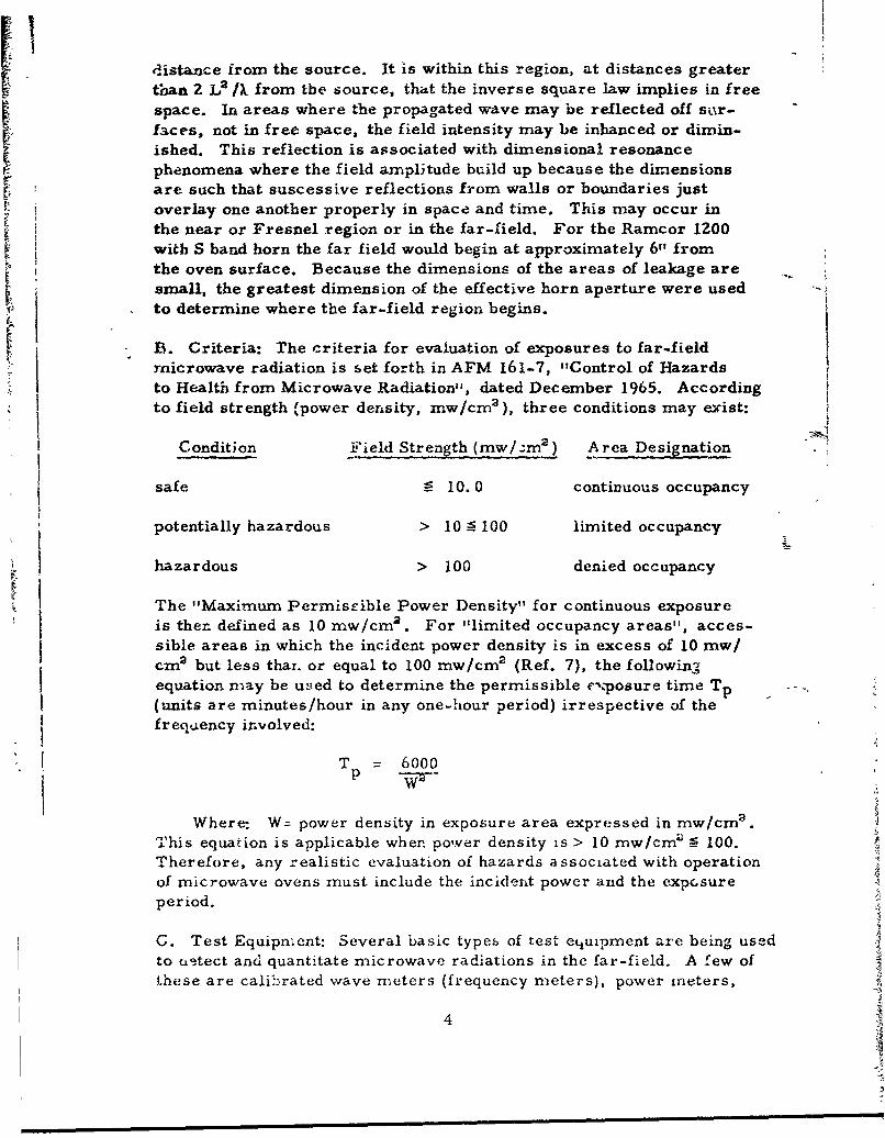
distance from the source. It is within this region, at distances greaterthan 2 L A/) from the source, that the inverse square law implies in freespace. In areas where the propagated wave may be reflected off sir-faces, not in free space, the field intensity may be inhanced or dimin-ished. This reflection is associated with dimensional resonancephenomena where the field amplitude build up because the dimensionsare such that suscessive reflections from walls or boundaries justoverlay one another properly in space and time. This may occur inthe near or Fresnel region or in the far-field. For the Ramcor 1200with S band horn the far field would begin at approximately 6" fromthe oven surface. Because the dimensions of the areas of leakage aresmall, the greatest dimension of the effective horn aperture were usedto determine where the far-field region begins.
B. Criteria: The criteria for evaluation of exposures to far-fieldmicrowave radiation is set forth in AFM 161-7, "Control of Hazardsto Health from Microwave Radiation", dated December 1965. Accordingto field strength (power density, mw/cm2 ), three conditions may exist:
Condition Field Strength (mw/:m2 ) Area Designation
safe - 10.0 continuous occupancy
potentially hazardous > 10 n 100 limited occupancy
hazardous > 100 denied occupancy
The "Maximum Permissible Power Density" for continuous exposure
is then defined as 10 mw/cm2 . For "limited occupancy areas", acces-sible areas in which the incident power density is in excess of 10 mw/cm 2 but less thax. or equal to 100 mw/cm2 (Ref. 7), the following1equation may be uned to determine the permissible cposure time Tp(units are minutes/hour in any one-hour period) irrespective of thefrequency involved:
T 6000
Where: W= power density in exposure area expressed in mw/cma.This equation is applicable wher. power density is > 10 mw/cmr _ 100.Therefore, any realistic evaluation of hazards associated with operationof microwave ovens must include the incident power and the exposureperiod.
G. Test Equipnent: Several basic types of test etiuipment are being usedto c±.tect and quantitate microwave radiations in the far-field. A few oft.hese are calibrated wave meters (frequency meters), power mneters,
4

field strength meters, test antennas, and test lights. For a basicdiscussion of these instruments, see Appendix Ill.
D. Biological Effects: Biological effects of exposure to microwaveradiation in the far-field have been described eisewhere (Ref. 3, 4, 5,6# 7, and 23). The primary response is an overall rise in temperatureof the exposed tissue or organ. Microwave ovens tutilize this biologicalresponse of energy absorption avd conversion to thermal energy in thepreparation of foodstuffs. Microwa;ve ovens for cooking foodstuffsoperate at 2450 MHz; for tbawing food, they operate at 915 MHz. Theeyes are most susceptible to the 3000 MHz frequency (Ref. 8). Between1000 and 300C MHz, absorption in the deeper body tissues tend to dimin-ish, depending on skin thickness, the total mass of body, thickness offatty layer, and the frequency of the energy (Ref. 9). Little informationis available as to the biological effect of exposure to the near-fieldradiations.
E. Results of Other Surveys:
1. Results: Results of surveys of leakage radiation from microwaveovens are shown in the following, Tables I-VI, to ahow the leakages thathave been found by others (Ref. 8, 9, 14, 15, 16 & 17). The extent ofthese leakages should indicate the magnitude of the hazard involved inoperating these ovens.
A

TABLE Ia
SUMMARY OF RELEtASED MICROWAVE INTENSITIES
Hinged VerticalDoor Sliding Door
Number of ovens monitored 58 18
Number leaking 48' 6'
Percent emitting < 1 mw/cmn2 17% 67%
Percent emlLting 1-i0mw/cmz 40% 33'V
Percent emitting > 10 mw/cm 2 43% 0%
Rentos, P. G. ' "Microwave Oven Sarvey - A Composite Report, "
Public Health Service Occupational Health Program, OccupationalHealth Field Station, Salt Lake City, Utah, 1968.
TABLE Ib
SUMMARY OF RELEASED INTENSITIES - ALL UNITS MONITORED
Hinged VerticalDoor Sliding Door
Number of ovens monitored 93 25
Number emitting > 10 mw/cm2 27 1
Percent emitting > 10 raw/cm 2 ?9% 4%,
(Amendment to Report by Rentos, 1968)
6
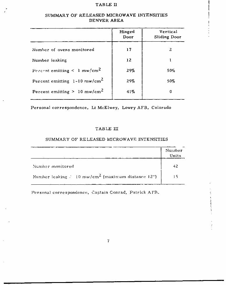
TABLE I.
SUMMARY OF RELEASED MICROWAVE INTENSITIESDENVER AREA
Hinged Vertical
Door Sliding Door
Number of ovens monitored 17 2
Number leaking 12 1
Percflnt emitting < 1 mw/cm 2 29%0 50.
Percent emitting 1-10 mw/cm 2 29% 50%
Percent emitting > 10 mw/cm 2 41% 0
Personal correspondence, Lt McElwey, LowryAFB, Colorado
TABLE III
SUMMARY OF RELEASED MICROWAVE INTENSITIES
NumberUnits
Number monitored 42
Number leaking - 10 trw/cm 2 (maximum distance 12") 15
Personal correspondence, Captain Conrad, Patrick AFB.
7

TABLE IVa
MICROWAVE INTENSITIES E.MITTED FROM CLOSED OVENS(Milliwatts/sq. cm)
Location of MeasurementsOven Description Face of Door Periphery of Door
I Left Side Top Right side
Bottom-hinged door 2 2 0 2open grill front 8 4 0 4mechanical lcck z 12 0 4
,zenerating tube 3 9 0 00 2 0 20 2 01 0 0
Bottom-hinged door 0 10 0 0open grill, mechanical 0 6 10 5lock, 2 generating 3 0 0 0tubes 2 4 0 2
__. 3 1 0 2 0
1 0 0 3
Vertical sliding 0 0 0 0door, open grill 0 0 0 01 generating tube 0 0 0 0
2 0 0 00 6 0 4
1 0 0 0Vertical siiding
door, open grill 0 0 0 02 generating tubes
Side-hinged solid 0 2 0 1panel door, mechanmcal 6 0 6 2lock, I generating 1 2 4 4tube
Bottom-hinged door 0 0 0 0open grill, magneticlock
Slirovic, i1. J., "Microwave Oven Radiation Hazards in Food-Vending.,Vst1,.shments, Archives Environmental Health (March 1967), "ol. 14
'3
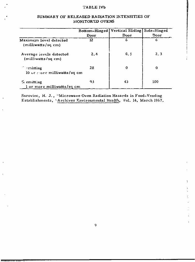
TABLE IVb
SUMMARY OF RELEASED RADIATION •ITENSITIES OFMONITORED OVENS
Bottom-Hinged Vertical Sliding Side-Hinged
Door Door DoorMaximum. level detected 12 6 6
(milliwatts/sq cm)
Average ievels detected 2.4 0.5 2.3(milliwatts/sq cm)
'-mi±ing 28 0 010 ur :-!ore milliwatts/sq cm
3 emitting 93 43 100
1 or more milliwatts/sS cm
Suroviec, H. J., "Microwave Oven Radiation Hazards in Food-VendingEstablishments, "Archives Environmental Health, Vol. 14, March 1967.
9

TABLE V
MICROWAVE LEALAGES ASSOCIATED WITH THE OPERATIONYOF VARIOUS MICROWAVE OVENS
Power Density*Oven Location of Milliwatts Per Square
Number Leakages Load 'entirneter (mw/cm2 ) RemarksI Front Dummy 5.0 [
Side Dummy 5.0
2 Right Front Dummy 10.0
3 ",one Dummy 0.0
4 Front Dummy 0.5 Only one magnetronj functioning.
5 Front Dummy 5.0 Door shims worn. Can20.0 crack door open without
unit shutting off. With
power switch on, warninglight on at all times. Lightbecomes brighter whencooking commences.
6 Front Dummy 5.0Side Dummy 7.3
7 None. Dkummy 0.0
8 Front Roast 1.0Side Roast 0.25
9 Front Sandwich, 5.0 Worn door shims preventedSide/Door immediate activation of
Ajar I I safety shut off.
flra'ysse, P. A. "Microwave Cookers", Occupational Health Bulletin, Vol.21, No. 10, 1966.
10

TABLE VI
SUMMARY OF SURVEYS BY US ARMY
Survey Number Number Number LeakingNumber Ovens Sur-,eyed Leaking9 10 >20I '
1 j 28 22 6 2
S32 4
Survey No. i Taylor, 68.Survey No. 2 Taylrr, i7.
2. Critque of Results: The percentage of ovens with leakage(Tables la and b, II and IV) was: vertical sliding about 12 percent;hinged door, 29. C percent. The majority of ovens shown in TablesI-V were not new and were located in public facilities receiving highusage. Therefore, oven construction is a critical factor as to leakage;and for ovens with higher usage, a greater probability exists that leak-
ages would occur. The age of these ovens and their high usage tendsto explain the high percentage of ovens that had leakages. Maintenance
of these ovens was on contract oasis. Rose, et al, (Ref J3) measuredenergy levels at a distance of 18 inches from the magnetron (high powertube) of a microwave oven, averaging 22 mw/cm2 at his abdomen. Theyconcluded that "Data available do not confirm the probability but do provethat adequate protection can be afforded the worker by use of a simple,
inexpensi,.e device tce intercept and absorb the microwave energy. Thedevice is a wooden frame covered with copper mesh sCreening whi.'h isplaced on the oven to shield the worker from the microwvave enrgy tolevels less than 5 n-w/cn-.''
lFor sirveys, Tables ii, III, and V, the oven to survey instrumentdistance, was not shown. Ti-,ls distance •vas from 2-3 inches for survey,Table IVa and b, and at the surface of the oven for Tables Ia, lb, andVI. In surveys, Tables ii, IV, V, ,,,r! VI, dummy load!, were usedsirmulating operating conditions. This was not establshd for surveys,Tables Ia and b, and II. Survey instrumcnt tsed in Tables Ia and b, and
"a,)le VI wos the Rarncor 1200, and in Table V tie Empire NF 157.Instrun,ent used was not established for Tables II and Ill. As previouslydlis( ussed, the, distance, from the oven at which leakage (power densities)arc. n ea!ured affects the reliability oi the nicasurenients; this distan eosh-i,11d be' at least 6 :nchehs if the-, measur ements are to be reliabl,".
11
IIt can be concluded from the proceding tables that leakages .rom
microwave ovens do occur. As previously presented (See Section I,this report), the causcs for these leakages are varied. In general,tae authors (Ref. 8, 9,14,16-18) did conclude that these ovens representa potential hazard.
1
o
lZ)
I__ | Wnnnn l nw mmmmuunn n Inz
SECTION III
SCOPE OF SURVEY
Surveys of 19 microwave ovens being operated at 12 Air Forceinstallations were accomplished. The amo-,nt of microwave radiationleakage from these ovens and physical cause of leakage, when possible,along with the condition of the interlocks was determined. Surveyprocedures for these determinations were those shown in Appendix IV.Survey instruments were the Empire instruments, Models 157, SerialNos. 181 and 195, calibrated 12 July 1968 and microlite (Probe) 287.
Determinations of the magnitude of hazard of operating these ovenswhen interlocks malfunction were also made. Fer these determina-tions, an oven of the sliding door type was brought into the laboratoryand operatcd with interlocks "jumped", door opended, and dumi-rjy loadinside the oven. The size of :he beam and the power densities of themicrowave field at various positions around thQ oven were determined.Ionization radiation was measured with a RF shielded Victoreen 440,survey instrument, Serial No. 306, calibrated 26 September 1968.
SECTION IV
SURVEY RESULTS
The results of field surveys of microwave ovens are shown inTable VII. Results of investigations in laboratory are shown in TableVIII. The locations of measurement are seen in Figure 1.
In the field surveys, Table VII, the energy escaping was found to)c drectional giving a narrow beam, usually parallel to the plane ofthe door for ovens with hinged doors.
In the laboratory investigation with the oven door open, the energyescaping is directional, but "ie beam i& extensive, extending to all sidesof the oven, 1800 from center froit of oven. With the oven door closedand no dummy load in the oven, only one area of leakage was detected;1/4 inch length of tube glow with the microlite, and 0.2 mw/cm2 with theEmpire 157. With dummy load, glass half full of water only a needledeflection was seen, using tne Empire 157 survey instrument. Noresponse was registered by the microlite 287. The operating proce-dure, for these ovens is to place food inside the oven which is normallylocated or. counters. The oven is activated for a pre-set period of time.and during this operation the operator can be in another area. The
13
I .. . . . .. mi~mmmmmm j m mm m m m m mm m im m m mm m i
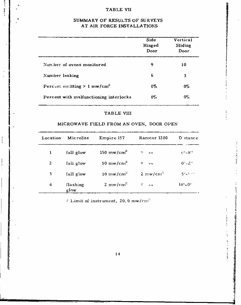
"TABLE VII
SUMMARY OF RESULTS OF SU RVEYSAT AIR FORCE INSTALLATIONS
Side VerticalHinged Sliding
Door Door
Nu.nber of ovens monitored 9 10
I Number leaking 6 3
Perccn:. emitting > 1 mw/cm2 0% 0%
Percent with malfunctioning interlocks 0% 0%
TABLE VIII
MICROWAVE FIELD FROM AN OVEN, DOOR OPEN
Location Microlite Empire 157 Ranicor 1Z00 D'stance
Ni
1 full glow 150 mw/cm2 * --2
2 full glow 50 mw/cm2
3 full glow 10 mw/cml 2 rnw/cnm' 5f-i
4 flashing 2 mwv/cmn' : -- 14'-0"glow _
-L Limit of instrument, 20. 0 mw/cn'
14

Figure 1
Location of Survey Points
>
V-4 0U)
15

operation time period is for several seconds to a few minutes andoperation is by more than one person or on self-service basis.These short operating periods and intermittant operation by any oneoperator result in short individual exposure. It is possible for theoperator to place his face or other parts of his body in close prox-imity of the oven. Probes have not been developed to measure theradiation within these near or Fresnel regions. Neither are thereany guidance or criteria with which to evaluate this potential hazardand util such guidance is available and instruments are developed to
measure these radiations, these exposures should be minimized (Ref22). To the most probably susceptable organs, the eyes and gonards,these exposurers should be prohibited.
Surface readings of ionizing radiation at the air intake and out-let of oven, front and back respectively, showed 0. 1 mr/hr.
SECTION V
DISCUSSIONS OF RESULTS & CONCLUSICNS
Two types of ovens are being operated on USAF installations.These are the hinged or the vertical sliding door, both operating at2450 MHz. All models were relatively new. Measured leakage,consisted of narrow directional beams, always less than 1. 0 mw/cm8
at the surface of the ovens, using the NF 157 survey meter. Leakagewas not detected six inches from the surface of th,: ov i-ns. Note, thatin using the NF 157 or Ramcor power density meters to measure leak-age from slots or small areas the intensity -f beam has been integrated,averaged, over the effective aperture of the antenna. Therefore,theseinstruments are not ideally suited for measuring the power density ofbeams of smaller cross sectional area than the effective aperture oftheir horn. But a conservative estimate of the actual power densitywithin these small areas would be the measured power density timesthe ratio of the effective aperture of the horn to the cross sectional areaof the leakage. Since no measurement was recorded at more than sixinches from the oven surface this would not effect the results of ourmeasurements. Therefore, the probability of a hazardous exposure tomicrowave radiation occurring during the normal operation (operationof ovens with interlocks not "jumped" and not damaged) of microwaveovens is remote. Likewise, there is no hazard from ionizating radiation.
The microlite-287 has proven adequate as a survey instrument formicrowave ovens. Microwave energy can be detected and field pattern ocan be explored, using this probe. The response of this prob.' -At onthcfrequencies is being investigated and will be reported later, hut theprobe does seem to have aoplication for detecting microwave energics
16
im im~lmmwmA
from other sources. It is inexpensive, quick, and responsive. Lengthof glow of microlite tube is proportional to field density.
Whether an oven leaks or the amount it leaks, in the absence ofsome element to perturb the radiation fields, is a function of such itemsas oven construction, age of oven, or usage oven has received, type ormanufacturer of oven, etc. Therefore, the periodicity of survey forleakage will have to be determined locally for each set of circumstances.None of the ovens checked (See Table Vfl, this report) had malfunctioninginterlocks, but they still require checking due to the magnitude cf hazardtheir malfunction presents.
Equipment for measuring and criteria for cvaluating the radiationswithin the near-field of leakage from microwave ovens are not a.ailable,but the energy levels within these regions may be significant (Ref 22).Until such time that the tools to evaluate this situation are available,these exposures should be precluded. The most common exposure to near-field radiations occurs when the cooking operation is viewed through theperforated panel, door screen.
In the laboratory investigation, Table VIII, the maximum credibleaccident that could occur was shown in measurement location No. 1.This measurement and measurement, location No. 2, were probablywithin the near-field and therefore must be considered ambiguous. Solern,et al (Ref 19) made oimilar evaluations of various ovens operated in ananechoiccharnber, a chamber designed to approximate freespace incor-porating suitable attenuation of reflected waves. At 12 inches from thecenter of the lace of the oven, they measured power densiies rangingfrom approximately 160 to 700 mw/cm 2 . They used a Ramcor 1200 Bwith S Band Horn and appropriate attenuacors. They concluded that"Although far field conditions are expected at distances beyond 30 cmfrom the open oven doors, the observed radiation power densitydecreases less rapidly than would be predicted frorr inverse square lawdeterminatiorns. Part of this effect may be caused by reflections fromrrthe floor" (Ref 19). We conclude a most serious condition would occurif an oven were operated with interlocks de;eated and the area in whichthe hazard would exist would be normally occupied.
SECTION VI
RECOMMENDATIONS
1. All ovens should be surveyed by Base Bio-Environmental Engineer
17
or Preventive Medicine T_"nnician initially and periodically withroicrolite-287 test lite. 'ý This survey should include both a physicalinspection of the integrity of the oven, test to determine wheth,:r
8 interlocks are functioning and measurement of leakage radiation.Survey procedures for these tests are shown in Appendix IV.tI
2. If leakage at 6 inche-., away from the face of the ove- causesmicrolite to glow full length of tube, the oven should be taken out ofservice for repair, which will usually be done on contract basis. Afterrepair and before oven is put back into service, it should be resurveyed.
3. If interlocks are not working, the oven should be taken out ofservice for repair. Before it is again placed in service, the interlocksshculdi be rechecked.
4. To minimize the potential hazard from exposures to near andfar-field radiations of leakages from these ovens, viewing of theseoperations or other actions which would result in the possible exposureto the near-field radiations should not be cundoned.
".Six of these lights are available from each of the USAF EnvironmentalHealth Laboratories.
I
Ji
18
-i

BIBLIOGRAPHY
1. T.O. 31Z-10-4, Electromagnetic Radiation Hazards, dated
1 August 1966.
2. Code of Federal Reg., Title 47, Part 18: Industrial Scientificand Medical Equipment that may Interfere with Radio Communi-cations, Government Printing Office, Washington, D.C. 20401.
3. Weiss, M. W. and Munford, W. W., "Microwave RadiationHazards,' Health Physics (June 1961), Vol. 5, pp 160-168.
4. Deichrrann, Wm. B., Ph.D. and Stephens, Frank H.,"Micru-
wave Radiation of 10 mw/cm 2 , " Industrial Medicine and Surgery(June 1961), Vol. 30, No. 6.
5, McLaughlin, John T., M.D., "Health Hazards from Microwave
Radiation," Western Medicine (April 1962), Vol. III, No. 4.
6. Seth, H. S., M. B. B. S. and Michaleson, D. J. M., "MicrowaveHazards Evaluation, " Aerospace Medicine (August 1964),
pp 734 -739.
7. "Concrol of Hazards to Health from Microwave Radiation,"USAF Manual 161-7 (December 1965), pp 3-4.
8. Breysse, P. A., "Microwave Cookers," Occupational Health
Bulletin (1966), Vol. 21, No. 10.
9. Suroviec, Henry T., "Microwavc Oven Radiation Hazards inFood-Vending Establishments, " Archives Environmental HealthtMarch 1967), Vol. 14.
10. Instruction Manual, Empire Broadband Power Density Meter,Model NF-157, The Singer Company, Metrics Division,915 Pembroke Street, Bridgeport, Connecticut.
]1. Handbook of Operation and Maintenance for Densiomneter Model
1200, T.O. Ne 33A-1#-12-284-1, Radar Measurements Corp.,190 Duffy Avenue, Hicksville, New York.
12. Advertisement Flier, International Crystal Mfg. Co., Inc.,10 North Lee, Oklahoma City, Oklahoma 73102.
19
II
13. Rose, V. E.; Gellin, G. A.; Powell, C. H.; and Bourne, H. G.,"Evaluation and Control of Exposures in Repairing MicrowaveOvens, ' an unpublished report.
14& Conrad, Captain Ronald G., Personal Correspondence (September1968), Patrick AFB, Florida.
15. McElwey, Lt David W., Personal Correspondence (October 1968),Lowry AFB, Colorado.
16. Taylor, J. R., "Microwave Survey No. 42-38-68", Food ServiceDivision, Walter Reed General Hospital (WRGH), Washington,D.C., 28-29 March 1968.
17. Taylor, J. R., "Microwave, Survey No. 42-13-68, Walter ReedArmy Medical Center (WRAMC), Washington, D.C., 7 September1967.
18. Rentos, P. G., "Microwave Oven Survey, Public Health Service,Occupational Health Program, Occupational Health Field Station,Salt Lake City, Utah, April 1968.
19. Solem,D. L. etal, "Report of Preliminary Measurements ofElectrqmagnetic Radiation Fields Near Microwave Ovens" TBSNO 5, Technical Services Branch, C~onsumer Protection andEnvironmental Health Service, National Center For RadiologicalHealth, Rockville Maryland'20852, Dec. 1968.
20. Near Field Radiated Emission Characteristics, Handout, "ShortCourse Microwave Systems and Spurious Electromagnetic Ra-diation", Elýctronics Division, Engineering Experiment Station,Georgia Instltute of Technology Atlanta GA 24 - 28 Feb 1969
ZI. Proceedings of a Meeting T9 Discuss Technical Considerationsinthe Measurement and Evaluation of Radiation Emission FromMicrowave Ovens U. S. 'Department of Health, Education, andWelfare, Public Health Service, Environmental Control Admin-istration, National Center For Radiological Health, Rockville,Maryland 20852, July 31, 1968.
22. Staff, "Personal Conversations", Electronics Division, EngineeringExperlinent Station, Georgia Institute of Technclogy Atlanta, GA,27 - 28 Feb 1969.
20
zoI
23. Moore, W. Jr.. "BIological Aspects of Microwave Radiation",
TSB4, U.S. Department of Health, Education and Welfare.Public Health Service National Center for Radiological HealthJuly 1968.
24. TO 33 AI - 7 - 69 - 1, Broaa Baud Power Density Meter,
Model NF 157, dated 15 August 1962
2.1

"APPENDIX IDEPARTMENT OF THE AIR FORCE
HEAD•QUARTERS UNITED STATES AIR FORCE
WASHINGTONI oc. 033
I~ . V. MFKPA
suac icrotave C .ens llJ II7.968
,-o AAC AIC MAC CINCUSFE AFWO
ADC AU CIMCPAC&i USAFS Phnoenixville PAAFCS USFWO SACAFLC HQ CMRD USAF TFA 1002 IG GPAFSC CAC USAPA Norton AFB Ca
(Surgeon)
1. Microwave ovens are being used with increasing frqzmency in the USAF.Food service facilitiba using these devices include hospitals, BXconcessions, dining halls, officer, NCO, and service clubs. It has beenreported that these ovens can emit excessive amounts of microwaveradiation because of malfunctioning interlock switches, poorly installedseals, or misaligned doors.
2. It is roqcested that you identify the bases within your command usingmicrowave ovens and survey each oven to insure that individuals are notreceiving excezs exposure. If trained personnel and calibrated equipmentare not available within your command, a consolidated list of those basesrequiring microwave oven surveys should be forwarded to HeadquartersAFLC (MCDPE), with an information copy to this Headquarters (AFMSPAP).
3. The provisions of this letter will expire 1 July 1969.
FOR THE CHIEF OF STAFF
H. C. DORRIS, Brig General, USAF, MCDirector of Professional ServicesOffice of the Surgeon General
2U
Underrt, r uYour Country 's M -Buy US. Savings Bonds.
;IP- PPENIDC H
'PARTOWENT OF or*# :-r £1 FCARCE
- ~ caafm- OO~~GS COWMAW X- ~ *T~.0SP4.AIUF0*CV SASI MSG4 453"3
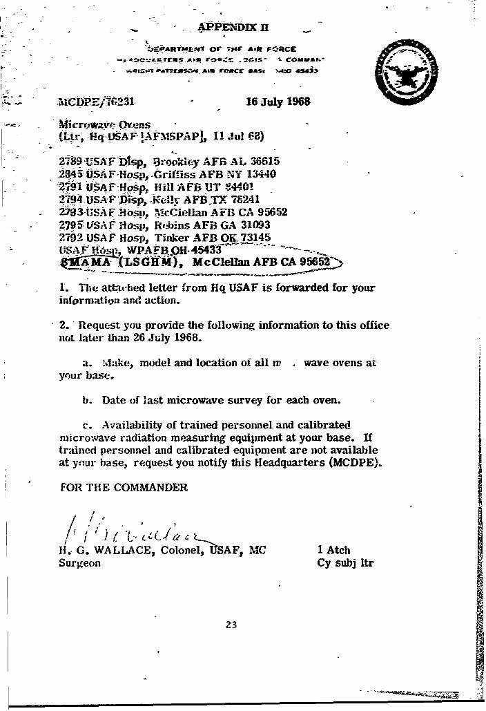
tc lp E, tr2 301 -16 July 1968
Mkrowavie rnsMLir- Hq USAF- !AFMSPAPI, 11 Jul C-8)
27-89 USAONDSP, rok FA 306615S.2S45SAF-Hosp6 Griffiss AFB NY 13440
#79 UA.P4!J~ o.p P.ill -A FB UT 8344-012194 USA F*Disp,, JEk111 AFB.TX- 782412793 USAf .1osp•, McCiellan AFB CA 95652
5295. LISA F Hisbp, R,.bins AFB GA 310932792 USAF Hosp, Tinker AFB OK 73145SUS;A .fC s-- WPAFBOl- 45433. -.$ M-AM•- fLSGH•M), McClellan AFB CA 95652__.•
1. The att-iced letter from Hq USAF is forwarded for yourinformation and action.
2. " Request you provide the following information to this officenot later than 26 July 1968.
a. ,Make, model and location of all w wave ovens atyour base.
b. Date of last microwave survey for each oven.
c. Availability of trained personnel and calibratedmicrowave radiation measuring equipment at your base. Iftrained personnel and calibrated equipment are not availableat your base, request you notify this Headquarters (MCDPE).
FOR THE COMMANDER
I " /.*/,f) { ,
H. G. WALLACE, Colonel, USAF, MC 1 Atch
Surgeon Cy subj ltr
23
-A

A PPEkDIX 131
EQUIPMENT DESCRIPTION
Enmpire Broad Band Power Density Meter Model NF-157:
This instrument is designed to measure average power densitiesfrom 1. 0 milliwatt per square centimeter (mw/cm2 ) midscale to2, 000 mw/cm3 . Frequency range is from 200 MHz to 10. 000 MHzfor either cw or pulse modulated signals. Components of unit are seen Ion pages 26 and 27 of this appendix.
The unit can be used for probing of high densit'y RF fields and for'.etection of hot spots or lealcage from antennas and other high powerco1Ap•o -its. Probe selection is function of frequency of energy to bemeasured. Position of sensing element in the probe is commensuratewith the specific energy to be measured. Read-out of power ievei beingdetected is directly in mw/cm3 . Scale Zs divided into forty divisions,each division representing 0.5 mw/cm3 . Step attenuator is providedwhich permits a choice from five coaxial sections ODB (XI) to 30 DB(XOOO), 0-2000 mw/cm3 .
NOTE: See T.O. 31Z-10-4 and 33AI-7-69-1 for more detaileddescription.
Ramcor Model 1200 (Ref 11):
This instrument is used for detecting and measuring VHF, UHFand microwave energy radiating from, bigh power transmitters andrelated equipment. The scale is a direct reading decibel scale, mid-scale "0" db mark is 10 mw/cm2 . Range is -10 db to +3 db scale read-.ng- ýr 1 to 20 mw/cm3 . Conversion from db to mw/cm3 is by chart.Five antennas are supplied with the instruments and cover the followingbands:
VHF (200 - Z25 MHz)
UHF (400 - 450 MHz)
L (1120 - 1700 MHz)
S (2600 - 3300 MHz)
C (5000 - 5900 MHz)
X (8500 - 10, 000 MHz)
24
*,-2 ,
The response of each horn is zct flat for range of frequencies it covers.Therefore, -for a given horn and enclosed attenuator, a calibration curvemust be provided.
Initrument calibration is with a signal generator and antenna capa-ble of ýrodfcing a field of 10 nw/c-ma. Field densit- should be within±Idb.
Microlite -7-287:
This survey instrument consists of a preignited neon lamp de-
signed to indicate a field intensity of 10 =-w/cma at 2450 MHz. Length
of glow along tube is a function of field strength, e. g., 114 tube lengthindicates 2 mw/cm2 , full length 10 mw/cm3 or greater. For any otherfrequency the microlite probe can be expected to respond differently.
Fluorescent Bulb:
The bulb is used as an indicator of presence of microwaves.Energy required to fluoresce bulb being a function of frequency,geometry of bulb, and field strength. Example: 8 watt bulb, seepage3O, this appendix, glows steadily if field strength is 18 - 20 mrow/cm2 , and flickers in field of 6 to 8 mw/cm2 (Ref. 13).
If fluorescent bulb is placed at surface of an oven, it may fluorescewhen subsequent readings with power density meter show that powerdensity at 6 inches is insignificant. The fluorescent bulb is not a goodsurvey tool to quantitate leakages but does have its use when checkinginterlocks.
25
ii 1 1 Ill 13
-p m�rv. rt.
a:
-�
\t�#__JSJ
-- -
1.I.
t � -
I-
4
?A� �S�t-�>
- I4
At
-I
I4;-I

xII~
I. Z7
7- 1 LN-
WY C.0
Lazo - -~
28I
.1 � I1-I.fb* I
N
II
'S
I S4
I'I
"I
S -I4
Ip
£7I -
'4
S *. - jU4 4- -
* �' 'pA
2 �'
. §144.
A' - I :1&t' �<y/(iaWs
* '�A �
29
W.4-
l*ý 41
§4ft

* APPENDIX IV
SURVEY PROCEDURES
Survey of microwave ovens is done in three parts: (1) physic'inspection of oven, (2) survey for leakage radiation, and (3) check ofinterlocks.
In the physical inspection, the surveyor should check to see if:door shuts tight, all screws, doors screens, and other parts are inplac4 etc. For, areas where parts are missing can be sources ofleakage. A strip of paper 1" wide and approximately 6" long can beused to check door seal. These are arbitrary demensions, With thedoo, open place the strip of paper at different positions along theperiphery of the door. Each time, closing the door and removing thestrip of paper. If there is considerable resistance to the removal ofthe paper the door seals can be considered tight. This is also agood check before placing an oven back into service that has beenfound to leak around the periphery of the door seals but should nottake the place of the other procedures discussed in the followingparagraphs:
Prior to making leakage measurements, determine from manu-facturer's plaque, or by other means, the frequency at which theoven operates. If it operates at 2450, the microlite probe can beused to accomplish this part of the survey. If the oven operates atsome other frequency, a broad band power density meter can be usedfor this part of the survey. These instruments can be borrowed fromthe USAF Environmental Health Laboratories. The ovens surveyed todate have operated at 2450 MHz. To locate the areas of leakage, operatethe oven empty (without dummy load), so that the least energy will beabsorbed; therefore, the leakage is maximized. These operating per- jiods should be limited to prevent excessive energy absorption bymagnetron tube and subsequent damage of the tube (Ref. 16, 17, and 18).Make surface measurements along the periphery of the door and screen(viewing window). Also, at any other site where an area of leakagemay be suspected (see preceding paragraphs). Now place a standard 150 Jml beaker containing 100 ml of water in the center of the oven cavity tosimulate operating conditions, resurvey the previously identified areas -of leakage. Survey distance should be 6 inches from surface of oven(outside the fresnel area, assuring good survey instrument response).
In checking the interlocks, place a fluorescent bulb (1-40 watts) inthe oven cavity along with a dummy load. Operate oven and with varyingamounts of pressure, open the door. If interlocks are functioning pro-perly, the fluorescent bulb will discontinue fluorescing as the door opens.If bulb continues to fluoresce, the interlocks are either malfunctioning orhave been jumped.
31