Embed Size (px)
Citation preview
f-«%,tm* tym*m*f» .«-^
AD-A021 726
TEST DESIGN PLAN, NEW ARMY BATTLE TANK, XM1, OPERATIONAL TEST I (TOP XM1 OT 1)
Army Operational Test and Evaluation Agency Falls Church, Virginia
January 1976
V /
DISTRIBUTED BY:
National Technical Information Service U. S. DEPARTMENT OF COMMERCE

Ar Ajr.endBen'- fc the test design plan, d»ted 1] Feb 76, 1« «ttached «t th« end cf b««lc decument .
1 KPOT: TDP-DT-(D1
X) CQ TEST DESIGN PIAN. i> NEW ANDY BATTLE TANK
XMI. OPEMTHMAl TEST 1 o <c
TOP XMI OT I
U76113
US ARMY OPERATIONAL TEST AND EVALOATION AGENCY 5600 COLUMBIA PIKE
FALLS CHURCH. VIRGINIA 22041
^k
JANUARY 1J;6 ■p.
«PfReVEl FN PUBLIC IEIUSE;
DISTIIMTieHWllilTEB
/ NATIONAL TECHNICAL INI- DRMATION SERVICE

T 1.
o r ltc ~lea~ : 1 r1
I'\
.. ,.
•
•
ttle T 1\
ratlcmal Teat 1 l.'U
t crews bot ~
of t
t I a t A . t rated te s t, a two-week p rtion
erationa l aspect.-. 1\.-o candidate and an . AlAOS tan vil l e uaed.
tvo vtll be tr3ined on tvo vill b trained on one be trained on th~ other
l"'fl USIFJED ~ "'CL-•te•• ... o• ,.,, ••ca ~ ,... • .,..~ •
I
- --
.. ., : .~ .)
CLASSIFIED
1. 0 CUDAL
2 . 0
3. 0
1.1 lDtroduction 1.2 Syet .. deecription 1. l Teet pur-JH)Ma 1.4 Teet objective• 1. 5 cope ad tactical coutut
1. 5.1 Scope 1.5.2 Tac:ical contu~ 1.5. !coloacr
1 .6 l eeuae addreaeed 1. 7 Teet •Ileetonee
TEST a.DITI s 2.1 Factor• 2.2 Approach to control procedur e
2.2.1 Taraet acquiaition 2.2.2 Mobil it 2 .1 . 3 A&Uit 2.2.4 Rate of fi re 2. : .5 OperatiODa1 firing 2. 2.6 Schedule 2 . 2.7 Other data acq hit ton
TA 1tEQO lll!M!ln S 3.1 Typea of data 3. Data required 3.3 Approach to collection r o dur
3 .3 . 1 Ti• da ta 3.3. 2 Hu.eD f&c tor 3.3.3 Main pD firing data 3.3.4 Machi.Depn f irina data 3.3.5 Mobility data 3. 3.6 Syet .. ca.patibility 3.3.7 AcUity data 3.3.8 Sipature data 3.3.9 Training data 3.3.10 Teat ecor .. 3.3.11 Failure data 3.3.12 Maintenance data
i '·
1 1 1 1
2 2 2 3
9 10 11
1 15
15 21 21 22 22 22 23 23 23 23 24 24
.0 AliALTS~S
4 .1 Gneral 2.5 . 2 FirU& results ~ 5
4.3 Tt.e ..aau!'ea 25 4. lellabi it~. avatlabilit , and sintainability (RAM) 25
.5 CvDai~bt c.-era 26
5. 0 29
AI&I.!VlA Tl 31
11
TABLFP
Number
2-1 Factors and Conditions
2-t offensive Target Acquisition
2-3 Mobility
2-4 Main Cur. Live Fire Matrix
2-5 Test Activity Schedule
3-1 Dendritic Elements
4-1 Matrlx for Analyses of Main Gun Firings from Moving Tank
4-2 Matrix for Analyses of Main Cun Firings from Stationary Tank
5-1 Vehicles
5-2 Targets
5-3 Instrumentation
5-4 Ammunltion
Page
5
6
8
10
13
15
27
28
29
29
30
30
FIGURES
Nuaber
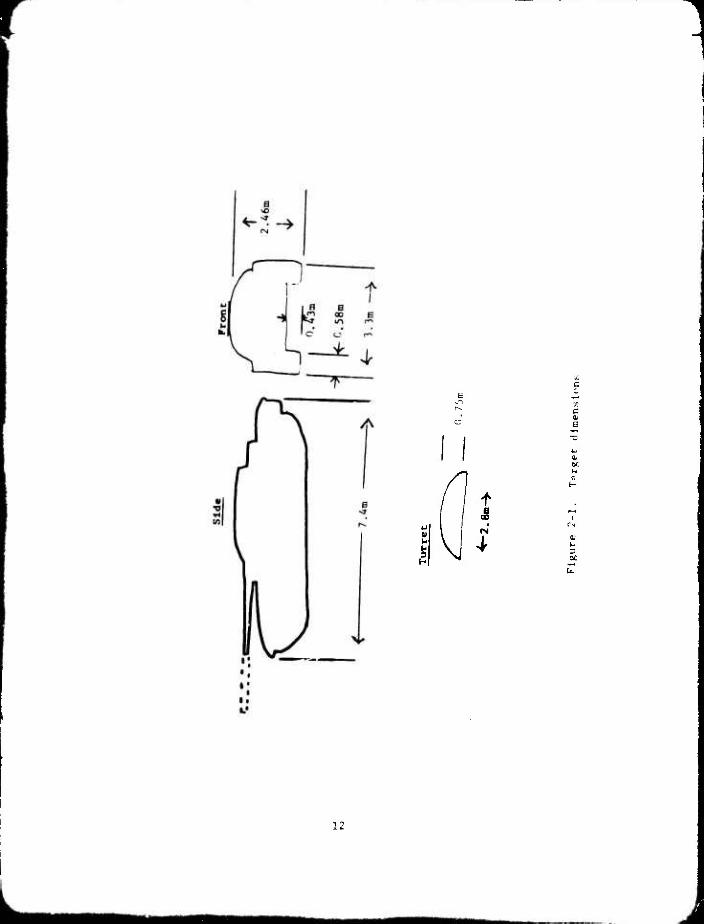
2-1 Target dimensions
3-1 Dendritic structure
Page
12
16
ill
1
TEST DESIGN PLAN NEW ARMY BATTLE
TANK, XM1, OPERATIONAL TEST I
1.0 GENERAL.
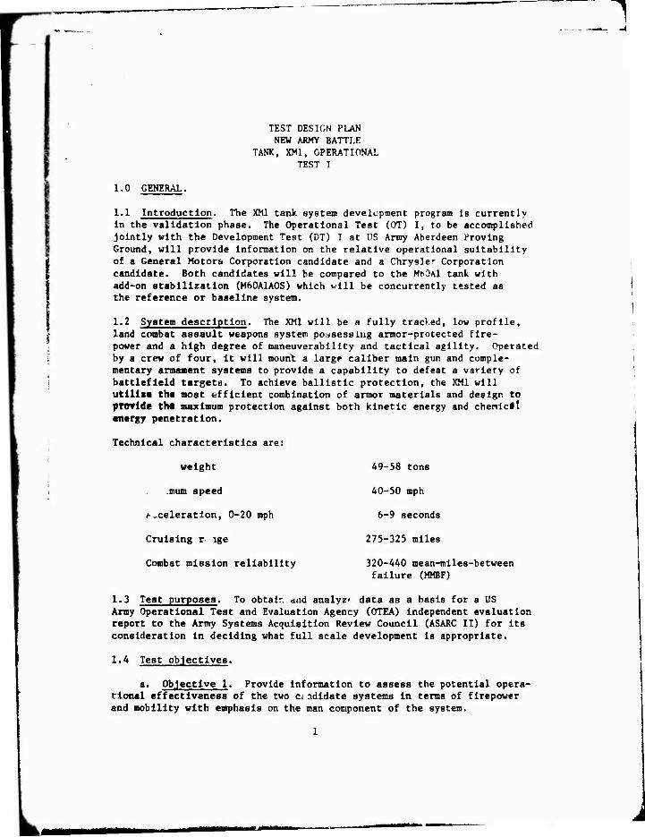
1.1 Introduction. The XM1 tank system development program Is currently In the validation phase. The Operational Test (OT) I, to be accomplished Jointly with the Development Test (DT) I at US Army Aberdeen Proving Ground, will provide information on the relative operational suitability of a General Motors Corporation candidate and a Chrysler Corporation candidate. Both candidates will be compared to the MtOAl tank with add-on stabilization (M60A1AOS) which will be concurrently tested as the reference or baseline system.
1.2 System description. The XM1 will be a fully tracked, low profile, land combat assault weapons system possessing armor-protected fire- power and a high degree of maneuverability and tactical agility. Operated by a crew of four. It will mount a large caliber main gun and comple- mentary armament systems to provide a capability to defeat a variety of battlefield targets. To achieve ballistic protection, the XM1 will utillxt the most efficient combination of armor materials and design to pfovldc Che maximum protection against both kinetic energy and chenlclt energy penetration.
Technical characteristics are:
weight
.mum speed
/-.celeration, 0-20 mph
Cruising r- ige
Combat mission reliability
A9-58 tons
40-50 mph
6-9 seconds
275-325 miles
320-440 mean-mlles-betwecn failure (MMBF)
1.3 Test purposes. To obtalr. and analyz» data as a basis for a US Army Operational Test and Evaluation Agency (OTEA) independent evaluation report to the Army Systems Acquisition Review Council (ASARC II) for its consideration In deciding what full scale development is appropriate.
1.4 Test objectives.
a. Objective 1. Provide Information to assess the potential opera- tional effectiveness of the two candidate systems In terms of firepower and mobility with emphasis on the man component of the system.
mmm

b . Objective 2. Provi e informati n froa Hhich insights as ~ the operational survivabilit of the two candidate svstems aa be gained.
c. Objecti-le 3. Provide information relative !. the adequacy of proposed personne l qualifications, training, and selec tion criteria.
d. Objective 4. Provide icfor.ati n on crew level maintenance aad ayat .. failures.
1.5 Scope and :a~tical cor-text.
1.5.1 ~· XMl Operational Test 1 will be c011 ined with velo~t
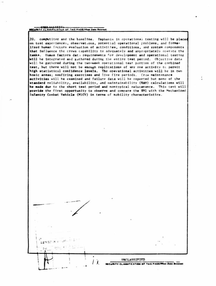
Test 1 at Aberdeen Proving Groun~, ~aryland, in a single integrated test, a tvo-veek portion of which will have articular a~phasis on orerational aapects. Two candidate ~1 tanks, one frOtn each c011petitcr, and an M60AlAOS tank wil l be used . Six crews will p•~ticipate in the operatioaal testinR : tvo will be trained on both competitors and the baseline M60AlAOS tank; two will be trained on one of the competitors and the baaeline; and tvo will be trained on the other co.petitor and the baseline. Eaphasis in operational testing will be placed on test ezperiences, observations, potential operational problema, and formalized huaan factors evaluation of activities, conditions, and syst .. co onents that influence the crew. caoability to adequately and appropriately operate the tank~ . Huaan fa ~tors data requir...nts for ~evelo~t and operational test1ng will be integrated and ~athered during the entire test period. Objective data will be Jtathered durtng the tvo-veek operational test portion of the cOIIbined test, b•.Jt there will not be enough replications of any one activity to permit high statistical confidence levels. The operational activities will be in two basic areas; nonfiring exercises and live fire periods. Crew .. intenance activities will be examined and fai!ure data will be reported but none of the staadard reliability, availability, and .. intainability (~\M) calculation~ will be mao~ due to the short test period and nontypical maintenance. This test will provide the first opportunity to observe and ca.pare the XMl with the Mechanized Infantry Ca.bat Vehicle (MICV) in ter.s of aobility characteristics.
1.5.2 Tactical context. Offense and defense activities will be simulated. In no case will any effort be aade to physically portray a tactical unit, nor will the test ~ c~ort .. ke an approach to extrapolatinR results to unit operations. Operational subtests will be conducted cnder operational conditions that are as realistic as tt.e and terrain allow.
1.5.3 Ecoloay. Envir0ft8efttal i8pact of this test is not considered to be significant.
1.6 Ia.uea addressed. This section, including test criteria, will be ca.pleted upOD approval of the OTEA IndepeDdent P.valuation Plan. It 1a anticipated that criteria for Operational Teat I vtll be based on the
2
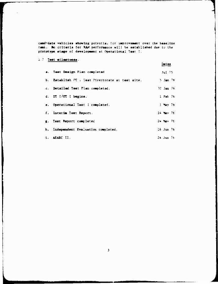
cand<dat« vehicles shoving potfntla> for iBproveaent over the baseline raai.. No criteria for RA/< perfomance will be established due cc the prototype stage of drvelopacnt at Operational Test I.
1. 7 Tggt «ll—tooea.
a. Test Design Plan coetpleteri
b. Establish OT i Test directorate at test site.
c. Detail««! Test Plan coapleted.
d. DT I/Crr I begins.
e. Operational Test I cosrpleted.
f. Inter la Test Report.
g. Test Report coafleted
h. Independent Evaluation completed.
1. ASARC II.
Dates
Jul 75
b Jan 76
3C Jan 76
1 Peb 76
1 May 76
14 lav 76
2«. >tav 76
16 JUT 76
2* Jun 76

2.0 T!ST COIDITIORS.
2.1 Facture. u tnti';1lc1q the tnt 1s to effect Oil ayat
The f~ctora shown in Table 2-1 have been identified the perfor.ance of the XHl. The aeneral approach in ayat-ticall vary hese condttiona and exaaine their
perfot"'Mnce .
2.2 !peroach to control procedure. Tvo basic areaa wil be covet3d in o~ratioaal activitiea, DODfirt~ field ~erciaea and live fire periods. DurlD t~e noofirin field exerciaea the pri .. ry areaa to be ex .. tned are 80bilit , aa1 l it , and taraet acquisition. Suppl.-entary ark&a of intereat will be inveatiaated tc the ~tent that tt.e peraita. To provide co.pariaon data a.ona the teat ve~iclea, the candidate XHl tanka froa each caapet itor an~ a M6 AlAOS tank will be evaluated under aiailar te.t concitiona. actical activities wil l be s~ulated, but no effort will be aade to phy&icall portray a tactical unit. Executi n of teat events vill be cont=olled y ..ana of a scenario developed .or the test and perfor..d in •uch weather as occurs at the teat in tallation. All teat vehicle vill operate each trial individually.
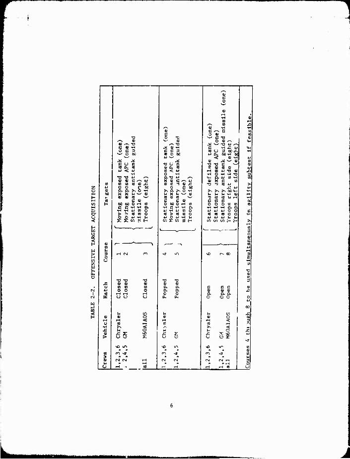
2.2 . 1 Taraet acgu i ai tio • Thia phase will be conducted in ~ ?arts ; offenae and defense.
a. The offenaive courses vill be 2 to J ka in lengt • Targets for acqui~ition vil l be both vin acd statiocary; th~ ~111 be~a.e available for acquiaition either y .aveaent cf the te.t tanka along the courae permitting line of aia t, or by aove.ent of the targets into line of aight from off-course positions. argeta vill be real and as repreaatative of the threat as poaaible. They vill include: tanka, APC'a, antitank guided aiaaile (ATCM) poaitiona, and l-ailbouettea for tank c~d r' a and loader' a aachineaun target a. The XKl candida tea vill ruD offenaive target acquisition under three hatr.h con~itiona; all open, all cloaed, and all cloaed except the tank co-=•nder'a batch popped. The M60A.l.AOS vill ruD UDder tvo hatch concUtioca; all open and all cloaed. Eight couraea vill be needed. Terrain liaitationa aay reatrict the aeoaraphical areaa--in aucb a cue a ccurae aay be chanaed by altertna aequence and location of targets alona a single avenue. !aeb courae 1a to be unique; aoving targeta are to be controlled ao as to portray tbe BaM aequence for e~ch crev/tank ca.bination. At leut one of the 110v!ng taraeu abo .a be a frontal aapect. See Table 2-2 for liatina of rum requireaents. A crew/tank ca.bination v111 run a particular courae only cnce. If tt.e for conduct of tb1a pba8e bec011ea a liaittna factor, tbe open hatch condition haa loveat priority. Stationary ~araeta are to be cued to tbe teat vehicles by a controller denoting an artillery at.alator or other applicable ..ana vbeD neceaaary.
4
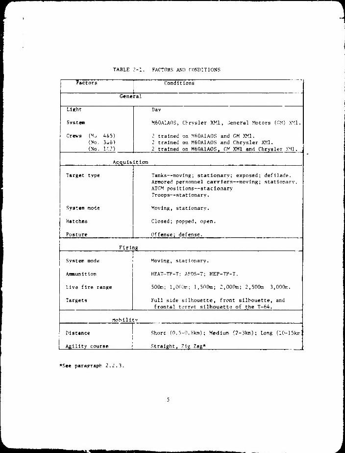
TABLE 2-1. FACTORS AND CONDITIONS
Factors Conditions
General
Light Day
System M60A1AOS, Chrysler XM1, General Motors (CM) XM1.
Crews (»I-, 445) 2 trained on MftOAlAOS and CM XM1. (No. 3^6) 2 trained on M60A1AOS and Chrysler XM1. (No. 1'?) 2 trained on M60A1AOS. CM XM1 and Chrysler XM1. j
Acquisition
Target type Tanks—moving; stationary; exposed; defilade. Armored personnel carriers—moving; stationary. ATOM positions—stationary Troops—stationary.
System mode Moving, stationary.
Hatches Closed; popped, open.
Posture Offense; defense. i
Firing
System mode Moving, stationary.
Ammunition HEAT-TP-T; APDS-T; HEP-TP-T.
Live fire range 500m; 1,000»; l.SnOm; 2,000m; 2,500m 3,00OIT..
Targets Full side silhouette, front silhouette, and frontal turret silhouett: of the T-64.
lobilltv
Distance Short (0.5-0.Slun); Medium (2-3km) ; Long (IG-ISkr'
Agility course 1 Straight, Zig Zag*
♦See paragraph 2.2.3.
1
a) ,-, -o c «) -H O C 3
^^ O 00
A: ji cue 3^
o M H M
M D o-
H W u Hi < H
w >
w K
o
a) oo
01 01 a en o _ o r t>c
a ^ o -H ■ ^ ^^ 0) x
01 0) (0 C 0)
00 60 O rH C3 C i^ "H W T-( 4J (D > f» « «0 O O u ft x 2: w P H
01 01
o
CO X
01 >
CO
I u
•o t) 0) 0) (a go o o
i-H t-H
03 >> g
vD m #• m ■*
CM 04
01
o < l-( ■< o
01 C 0 TD
v.- 0)
X 0) -H C C 3 0) O 60
t3 U C Or CH 0} 01 < 4J O -H o.-a X (U
o c oo
c 01 00 O rH
> (0 10 O « iH
^
(0 « 4J 4-1
w a» a a o o
r
3 to
(0
4)
0)
3
0) 01 m ki 3 o U
MMMM

b. The defenulve area target acqi'lsltlon exercises will be con- ducted from stationary tanks with closed hatches on the M60A1A0S rmd with the popped mode on the XMl's. Each crew/tank combination will occupy at least tw» defensive positions. Additional positions may be added if time and resources permit. Targets for each position will be one *ank, on" APC, and one truck; all will be moving and as repre- sentative of the threat as possible. The mobility dash may be incor- porated in this part of the target acquisition exercise if a suitable area can be found. The dash would represent movement from a primary to an alternate or supplemental position within the same defensive area.
2.2.2 Mobility. The matrix at Table 2-3 describes the conditions for the required mobility exercises. Exercises 1 and 2 will be accomplished using operational test drivers and tank commanders during mileage accu- mulated for development test purposes if possible. Exercises 3 and 4 could be conducted at Gunpowder Neck If vehicle transportation becomes a problem. Exercises 3, 4, and 5 pre conducted with full crews. The longest run is to represent a situation In which the tanks will simulate a movement to reinforce. To best represcit that tactical situation, the tank should leave a simulated assembly area, drive all but the last kilometer en secondary roads with the last kilometer on cross-country terrain, and occupy a defensive position. The mid-length run is to coamence with the tank in a defensive position, move on a cross-country route, and end with occupation of a different defensive position, ''"he short run can be combined vith the defensive target acquisition exercise described above or can be run separately, representing either the same defensive situation or a final assault from a covered position to ar objective. All mobility exercises are to be conducted with tracks in combat configuration. Hostile attempts to track test vehicles are to be made during this phase If feasible (see paragraph 2.2.3, below).
2.2.3 Agility. This part of the DT I/OT I will p-^err.pt to examine the capabilities of the candidate vehicles, as compared to thi> baseline M60A1A0S, to avoid presenting a high hit probability targftt to a threat tank or antitank guided missile. In this exercise, each crew will drive each tank for which it is qualified froir a covered position within ranpe of and in the field of view of a realistic threat tank and Ali...' position. Two cross-countrv courses are to be used: one a straight line requirinp icceleratlon and deceleration, the other a zig-zag. Both courses are tc be run at the maximum capacity the crew/tank. The acceleration/ deceleration courses should be relatively straight and require cycles of acceleration followed by deceleration t«- -trawl speed If possible, the deceleration should be forced by minor ohotacles; however, If the terrain available is not conducive to this, then deceleration must be forced bv control measures. The zig-zag course should also he terrair oriented, but may also be based on control measures If necessarv Course layout for the zig-zag'weapon fire course Is to be made with due consid?ratior. to the emerging results of I'S Army f'ombat Developments Experimentation Command antitank missile test experiment. In all agllltv events, the

TABLE I'- i. ^■RIUTY
Mobility Aberdeen Minimum Exercise Vehicle a/ area Length «epllcat lens
1 ATRs, M60 Churchvllle in-lSkm 1 each crew/ veh combination
2 ATRs, MbO rhurchv'lie :-3kr 1 each crew/ veh combination
3 PVs, MfO Perrvmau 3,- :- 3kK 1 each crew/ veh combination
4 PVs, M60 Perrvman - ^Oi.-HlVV, 1 each crew'
veh combination
5 PVs, ^60 Gunpowder Neck
jnfi-^oom | each crew/ veh combination
a/ ATR—Automotive test rip. PV~Pilot vehicle.

tanks are to be run et the maximum pt-rformance levels the crews can achieve/sustain. The threat will be stationary, Intitruraented to deter- mine gun lay, and will cor.t Inuouslv attempt to track the te-.ted tanks. Threat gunners are to be Instructed to track with the cross-hairs on the tanks and not to apply a lead. Fstimated length of courses Is to be such that the baseline M60A1A0S will require 15-20 seconds to traverse. Course length or duration Is to be flnaliv established bv the ooeratlonal test director, based on observat.Dn of pilot testing, so as to portray a reasonable covar-to-cover operational situation. Additional attempts to track test vehicles by hostile gunners are to be made during all other uhaaes of this test where the test vehicles present a reasonable por- trayal of operational action.
2.2.4 Rate of fire. This Is a deveiopner.t test oriented subtest that will be conducted with the cross-trained operational test crews. The subtest Is described In the DT I plan and will be run bv the develop- ment test direct irate during Its portion cf the test.
2.2.5 Operational firing. The matrix at Table 2-4 describes the con- ditions for the conduct of the operational firings. Hie matrix Is set up for one tank and one crew. Fourteen such natrlces will be fired during DT I/OT I In accordance with the acti"!!1' schedule at ''able 2-:'. As shown In Table 2-5, onlv one day's range time Is available for each crew/tank combination. This limitation dictates that each crew/tank cotnbinatlon attempt to limit non-matrix firing requirements. The prc- cec . e for this will 'e that each crew will first boreslght and then fire a confirming round for each tvpe aramunltlon to be fired for the XM1 candidates and with APDS onlv for the M60A1AOS. If the confliming rounds are successful, zeroing will not be done. If the confirming rounds are not successful, zeroing with the tvpe ammunition not con- firmed must be done prior to matrix firing. Main gun targets will be silhouettes painted olive drab; these will be representative of a front, side, or turret view of the 264 tank. Because the targets are two dimensional, engagements should be as near as practicable to a perpendicular fror, the firing tank. Speed of the moving targets is to be varied between 10 and 15 miles per hour. Target dimensions and shapes are shown at Figure 2-1. Tonduct of fire must assure that somt- targets be engaged Ir paired sequence. It Is desirable that three such pairs be established for gunner firing and one pair for tank com- mander firing. The particular r.-iLrix cells selected for paired engage- ments is dependent on the range capabilities but it is desirable that Lne two targets in any single sequence be at different ranges. It is anticipated that when a moving target is included in a sequence, it will be most convenient that It be engaged first. Since only one moving target will be available, a sequence requiring two moving tar- gets will not be possible. Suggested pairings are Indicated or Table 2-4, but final selection must await detailed planning. All firing la to be done with primary sights unless a failure occurs in theae elements of the system; if the failure is not easllv repairable.
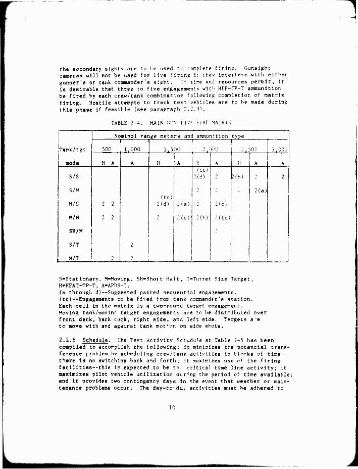
the secondary sights are to be used to romplete firing. Cunslght cameras will not be used for live flrlr.e If thev Interfere with either gunner's or tank, commander's sight. If time und resources permit, it is desirable that three to five engagements with HKP-TP-T ammunition be fired by each crew/tank combination following completion of matrix firing. Hostile attempts to track test vehicles are to be made during this phase If feasible (see paragraph 2.2.3).
TABLE 2-4. MAIN Gl'N LIVF FIRF MATRIX
Tark/tgt
mode
Nominal range meters and ammunition tvpe
500 1,000 ' 1
1,500 2,000 2,500 3,000
H A A H A H A 1! A A
S/S
S/M
M/S
M/M
SH/M
S/T
M/T
2 2
2 2
2
(tc) 2(d) 2(a)
2(c)
(tc) 2(d)
-1
2(b)
1
2(c;
2(tc)
2(b) -1
2(a)
2
1
S-Statlonary, M-Movlng, SH-Shoit Halt, T-Turret Size Target, H-HEAT-TP-T, A-APDS-T. (a through d)—Suggested paired sequential engagements. (tc)—Engagements to be filed from tank commandtr's station. Each cell in the matrix is a two-round target engagement. Moving tank/movinf target engagements are to be disfibuLed over front deck, back c^jck, right side, and left side. Targets a e to move with and against tank motion on side shots.
2.2.6 Schedule. The Test Activity Schedule at Table 2-5 has been compiled to accotrpllsh the following; it minimizes the potential trans- ference problem by scheduling crew/tank activities in blTks of time — there Is no switching back and forth; it maximizes use of the firing facilities—this IF expected to be th critical time line activity; It maximizes pilot vehicle utilization aur<ng the period of time available; and It provides two contingency days in the event that weather or main- tenance problems occur. The day-to-da^ activities must be adhered to
10

as scheduled In order to avoid loss of crew parrlclpation In a cross- section of actions. Crew/tank activities will be run onlv on tht? dav ■jcheduled or the makeup davs. Activities will be skipped if necessarv In order to adhere to the schedule. "Tie nakeup days mav be run if r.aeded, but must be held to the end of a crew/tank time block ^so the most crucial activity missed may be nade up. The decision on which activity is most, critical is to be nade by the nT deputv test director In cor.lunction with evaluation division. If on anv d^v the scheduled activity for a crew/tank combination is completed earlv, the time reralning can be devoted to exanination of areas not otherwise rovered, ^r areas In whlcb difficulties have been noted. Data requirements given In Section 3 have prloritv; others mav be added at the discretion of the operationa. test director upon noting problems.
2.2.7 Other data acquisition. In addition to the ma'or area? of acquisition, mobility, agllltv, and firing detailed above, there are several smaller scale activities on which data are required and which are to be accomplished whenever the opportunity occurs. These activi- ties are explained below.
a. The maintenance activities ideniified in the X>!1 operator's manual and additional crew maintenance duties as identified in the traln- tenance allocation chart will serve a=, the basis for determining the crcwa' ability to maintain the vehicles and provide Insight inco main- tainability characteristics of the XM1. Dally preventive maintenance (PM) services will be conducted on a before, during, and after aera- tions acheuule. Crews will inspect, test, service, or adjust those items specified in the operator manual at the time Intervals prescribed. These PM activities will be observed by a trained maintenance data collector and the adequacy of those services recorded. Additional crew maintenance tasks to be accomplished and time are: replacement of a track section (4 blocks); removal and replacement of a complete track; drive sprocket reversal; removal and replacement of sights where this Is a crew function; and machlnegun barrel replacement, vehicle avail- ability permitting. Maintenance activities, which occur naturally during testing and are performed by the vehicle crew, will be recorded In detail.
b. Use of secondary sights will be primarily from a human factors point of view and for the gunner in particular. All live matrix firings (Table 2-4) will be done with tv p primary sight unless a failure occurs. Some live firing (three to five two-round engagements for each crew/ tank combination) with the secondary sight Is desirable if time remains in the activity schedule after matrix firing. These secondary sight engagements nay be made with HKP ammunition. Choice of engagement ranges and tank/target modes Is tu be at the discretion of the deputy director for operational testing.
c Use of manual backup systems (i.e., turret rotation, main gun elevation, and manual firing procedures) for the main gun are to be
il
■JMM
n
■r. c il B
0/ Of
3
12

1
TABLE 2-5. TEST ACTIVITY SCHEDULE
Day MSDAIAOS G 4 Chrysler
Crew Activity Crew Activity ■
Crew iActivity
-7 1 u i
-6 2 M i 1 ! -5 1 A -4 2 l A 1 -3 1 F -2 2 F i L -1 Make up 1
T A 1 M 3 j F 1
2 6 A 4 F 2 | M
3 5 F i A 3 1 M , U 6 F 4 M 2 A 5 5 M 1 F 3 A 6 6 M 4 A F 7 3 A 5 1 M 8 4 A 2 M 6 F 9 3 F 5 M 1 A
10 4 F 9 A 6 M 11 3 M i A 1 F 12 4 M •7 F 6 A 13 Make up* 1/. Make up .
*Make-up day 13 should be Inserted at day 7 if any problems occur in the first comvlete iteration (days T through 6). The remaining iteration will be slipped by one day in that event.
M~Mobllity/Agllity. A—Acquisition. F—Firing.
13
1
accompÜBhed by all crews. Live firings with the manual procedures will only be done if the primary systems fail and cannot be repaired qoickly enough to permit complet'in of scheduled exercises.
d. Boreslght procedures will he performed primarily fron, a human factors point of view. Each crew will accomplish at least one boreslght prior to the firing exercises. It is desirable that all crews do this
more than once; however, crews 1 and 2 should complete three to five boreslghtlngs to assure familiarization and comparability of data. Time to accomplish the procedures is of major importance and will be recorded
in detail.
e. Use and operation of loader's and tank commander's machineguns. To include loading and reloading on the move. For the tank commander's machlnegun, reloading is to be accomplished from all the various on- board ammunition stowage locations.
f. Immediafi action procedures for all weapons, stoppages or ralslires if no actual Incident occurs.
Using simulated
14

3.0 DATA REQUIREMENTS.
3.1 Typ«a of data. To fulfill the test objectives, OT I will make use of objective and subjective data. Objective data examples are: tine to engaga, time to complete mission, targets detected, recognized, and engaged, and hlt/mlss. Subjective data will be collected using crew conaents and expert opinions. Human factors data will be gathered through the entire DT/OT. Requirements for both portions will be inte- grated and the area of human factors will be considered a combined sub- test. The description of human factors data in this test design plan Is to eatabllah the relation of the body of data from both development and operational portions of .he overall test to the requirements estab- lished from an operational point of view.
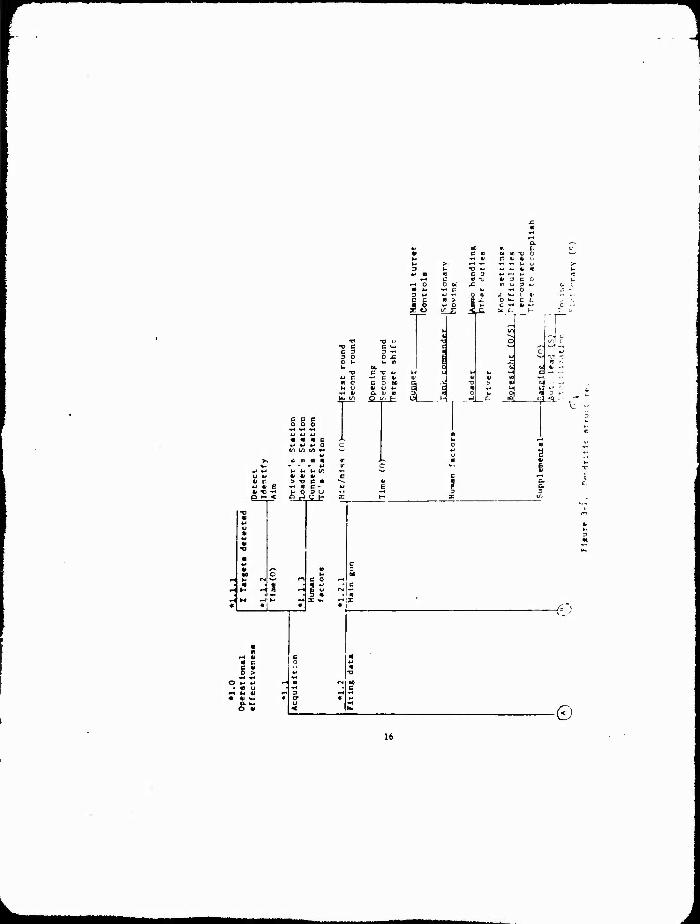
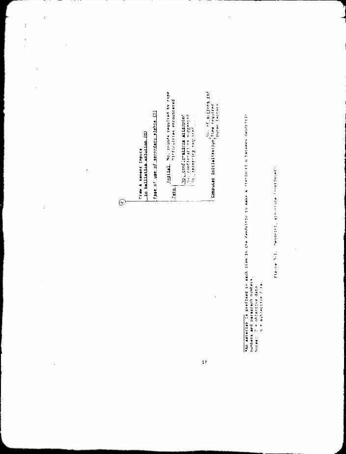
3.2 Data required. TVe relationship of the subtests described in Sec- tion 2 to the dendritic elements Is shown in Table 3-1. The dendritic structure at Figure 3-1 shows data requirements as related to the test objectives.
TABLE 3- ■1.
Saht—t nendrlMr F.l«ii«.nta
Acquisition *1.1: *2.1; *3.0; *4.0
Mobility *1.3; *1.4; *2.0; *3.0; *4.0
Agility *2.1; *4.0
Live Fire *1.2; *3.0; *4.0
3.3 Approach to collection procedure. The following paragraphs discuss considerations of data collection methods and are keyed to the dendritic elements.
3.3.1 Tlwe data. Acquisition time-line data (*1.1.2) will be collected by the data collector riding the tank. Tape recording of the tank inter- com will provide a backup. Interval uliies will be of greatest importance In analyses. The time line from target available for detection (or cue) to final aim may be further subdivided If appropriate. Detection time is the time of first indication by any crew member that a target has been spotted. Identification Is when the gunner has found the target In his sight, aim Is the tine when the gunner has laid on the target and announces that he has fired. Gunslght cameras are to be used to con- firm that Identification and aiming by the gunner have in fact occurred
*An asterisk Is prefixed to each Item In the dendritic to make a distinction between dendritic numbers and paragraph numbers.
15
1
ti 3 C O
U to
fc K -< « C - 41 Tl ^ u o 3 U ,, ^ 3 3 O f-" < O .J C H E H X Ul
l-o m «J u i u «
■o
■ u c • m 3 •0 O h t)C I* r* S-' (-1 C 0 m S 9 ^ •1 C H H n ^ (M N-l
5 m • 1 4 M ^ H ^ X «M »^ x « « « « /
V
e • ■ c o «J
gs w 9
»« ** O *J «J H n IN M
. « u •-I c « h « -■ 3 « 41 •« « cr «
^^ < NM -f
€J
© 16
L
M i
31 i
lit 5 1 t
0> C. «-I
V \
c^>- ■
c «. ■
« « -. ». a. K e t
« fc —■ ; t. -• X ■ • x r
a c r i -c I i
17

^
« V
'Is'
(^f-
r
■ -o
■ O VK
G>
18

*M a «« c rj
I rs* r^ ^j ^n
. n o r-i
00
5 c C
r- IS « u H
1"

1
*AiO Malntendnce and failure
*i.l
Malntenrnce
act ions
^.2 Failures
. 1 ..■
llH/ Kt^I t It s encouiu i i • ■; In crew r <; -. t.
£11 Mr.1 to i ' ■ r t" c rr, 1 rrr t j l : I o a c t I > i
Pu i 11 - 1 •. t'-sr cgu 1 prf r.t rer i"orrMtici
Nur Kt r rr^j desc r 1| tli J l. i.re J r
'cm r: |-t 1 C'n nf f el 1 'ir L l-^an .ird i -. J K
Failure rh.ir>T.pabl 1 Ity h*Z.k Repair p.-irts uned
Tieure 3-1. DendrliIc true tare (continued) .
20

for main or coaxial pun tarcets. Prlnie interest In tine of acquisition is for the main pun. Data collection ludpnent will be necessarv for determlnlnp time when aiin has occurred for conmander's and loader's machlneguns. As a general rule, this will be when the data collector decides the machlnepur. Is pointed in the direction of the target.
3.3.2 Human factors. Human factors data ror acquisition, dendritic element *1.1.3, is onlv for those considerations related to acquisi- tion. This Information lb to be gathered by means of a structured Interview and Is to be referenced to the hate' conditions for which It applies.
3.3.3 Main gun firing data. ''Dendritic element *1.2,1.)
a. Hit senslngs from the ra.'ige television svster. are to be ^o .- firmed bv photos or other means. Impact points are tn be recorded
b. Times are to be collected bv the collector on the tank. Opening time begins with the first word of the fire command and ends with the firing of the first round. Second round tine Is the time from firing of the first round to firing of the second round. Tar- get shift tiiie Is the time fron firing 'he final round at the first target to firing the initial round at the second target.
c. Human fa.tors data related to crew perfornar.re are to be gathered bv neans of structured interview with each crew member. Instrumentation will be utilized to the extent possible to obtain objective data on environmental and safetv conditions related to crew positions. This mav be limited bv the requirement that It not Inter- fere with crew operations. Of specific interest is an examination of any actual or potential confusion on the part of the loader in determining the location in the rack of the type round called for In the fire command. Accesslbilltv of all on-board main pun ammunition should also be addressed.
d. Supplemental data will require the following.
(1) Impact points for all zero and confirming rounds.
(2) Ringe used for eacb i.pagement. Number of re-rangings due to multiple returns, and if practicable, the time required to re-range.
(3) (.unner debriefing on auto lead.
(4) Gunner debriefing on stabilization effects for both moving and stationary engagemonts.
21

(5) Gunsight 'taneras are ro be used on all tr.aln k!un enRagenencs where possible. It will probablv not be possible to use the punsipbt camera on certain eiiKagements, t'ependlnp on the requirements for its Installation. (For Instance, on tbe ta;iV comnanaer eneagements If the gunsight camera installs in place of bis evepicce.)
(b) Hn-board or telerefrv recording is hlghlv desired tc determine Inputs to the ballistic computer for main gun firings. This should include both automatic sensor Inputs and manual control Inputs ( .ft., armunl- tlon selection). Detailed requirements ano capabilities trust be deter- mined hrough continuing discussions with the Prolect Manaper, test Integration working group, and contractor personnel.
(7) boreslght operations and computer initialization will be con- ducted and reported with a -articular emphasis on complexity cf required actions.
3.3.^ Machinegun firing data. :>ubtective opinions will be obtained by both the collector and punnei on target coverage with the machine- gun. Time to cover tbe targets w'll be gathered bv the data collector. Particular attention should be paid tc ''leid of '"ire provided the loader's machinegun, ease of moving it fror one pintle position tc another, and any inierference with the tank commander's machinegun or Its field of fire.
3.3.5 Mobility data. The obtaining of mobilitv data will require stop- watch time cr. short, medium, and long distance segments. rrew opinions are to be gathered and related to terrain tvpe for each crew position regarding comfort and safetv.
3.3.6 System compatibility. Three areas will be checked for svster compatibility: tactical systems, maintenance and transportation equip- ment, and on-vehicle stowage. In all cases the main data requirement will be to look for and record any difficulties.
a. If the MICV is available, it will run the mobilitv courses and time to complete them must be gathered as for the tanks.
b. Bridging compat Ibillt v v'1.l be tased on observations of the tanks crossing the armored --t' tele launched bridge (AVLB; . This may be Integrated into either the mobilitv or acquisition phases of the test.
c. M60A1AO? compatibility wUh XM1 candidates will be based on observations and data gathered throughout the test. No unique data requirements or collection effort is required for this dendritic element.
d. The VTR is to be used to remove power packs, winch, and tow the candidates. Data required will be observations of anv difficulties
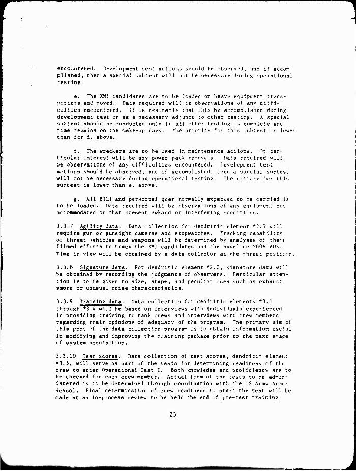
encountered. Development test actions should be observed, ind if accom- plished, then a special subtest will not he necessary during operational test in«.
e. The XM1 candidates are to he loaded on heaw equipment trans- porters and moved. Data required will be observations of anv diffi- culties encountered. It Is desirable that this be accomplished during developaent test or as a necessarv adjunct to other testing. A special subtesc should be conducted only li all ether testing is complete and time remains on the make-up davs. ''"Vie prioritv for this ..übtest is lower than for d. above.
f. The wreckers are to be used In maintenance actions. Of par- ticular Interest will be any power pack removals. Data required will be observations of any difficulties encountered. Development test actions should be observed, and if accomplished, then a special subtest will not be necessary during operational testing. The prlmarv for this subtest Is lower than e. above.
g. All BILI and personnel gear normally expected to he carried Is to be loaded. Data required vill be observations of any equipment not accomnodated or that present awkard or interfering conditions.
3.3.7 Agility data. Data collection for dendritic element *2.1 will
require gun ov gunsight cameras and stopwatches. Tracking capability of threat /ehlcles and weapons will be determined by analyses of their filmed efforts to track the XM1 candidates and the baseline M60A1AOS. Time in view will be obtained bv a data collector at the threat position.
3.3.8 Signature data. For dendritic element *2.2, signature data will be obtalnad by recording the Judgments of observers. Particular atten- tion is to be given to size, shape, and peculiar cues such as exhaust smoke or unusual noise characteristics.
3.3.9 Training data. Data collection for dendritic elements *3.1 through *3.4 will be based on interviews with individuals experienced in providing training to tank crews and Interviews with crew members regarding their opinlone of adequacy of the program. The prlmarv aim of this psr' nf the data collection program ib to obtain infonnatlon useful in modifying and improving th»" training package prior to the next stage of system aco'ilsttion.
3.3.10 Test scores. Data collection of test scores, dendrltir element *3.5, will serve as part of the basis for determining readiness of the crew to enter Operational Test I. Both knowledge and proficiency are to be checked for each crew member. Actual form of the tests to be admin- istered is to be determined through coordination with the I'S Army Armor School. Final determination of crew readiness to start the test will be made at an in-process review to be held the end of pre-test training.
23

3.3.11 Failure data. For dendritic element *4.2, all equipment Inci- dents (failures and/or malfunctions) which occur duri'.g the test period will be recorded. Time and test resource constral'-.us are such that no numerical estin.ates will be made in the areas 01 reliability, availabi- lity, or maintainability. Incidents which are recorded will be cate-
gcrlcally classified so as to correctly assess the chargeablllty of the Incident to equipment failure, crew error, accidental damage or other appropriate categories, unscheduled maintenance services will be pro- vided by APC shops when necessary. The capabilities and personnel of these facilities do not represent the normal type of maintenance facility which would be exercised In an operational test. Actual maintenance times and equipment downtime will be recorded, but as a result of the artificial nature ot the maintenance facility, these data will not enter into any RAM calculetlons. Repair parts used during the test will be recorded and reported. No form of logistic support concept will be evaluated.
3.3.12 Maintenance data. For dendritic element *4.1, crew maintenance data will be collected during performance of daily, scheduled, and un- scheduled maintenance. Operator maintenance will be performed In accor- dance with appropriate maintenance manuals. Time to perform each scheduled and unscheduled maintenance task will be recorded along with the date-time group, operating hours, tachometer hours, rounds fired, and vehicle miles at the time of the incident. Operation and utility of built-in test equipment will be examined. Failed components will be identified and reported. Each malfunction will be identified with sufficient information to determine Its chargeablllty as a failure.
2A
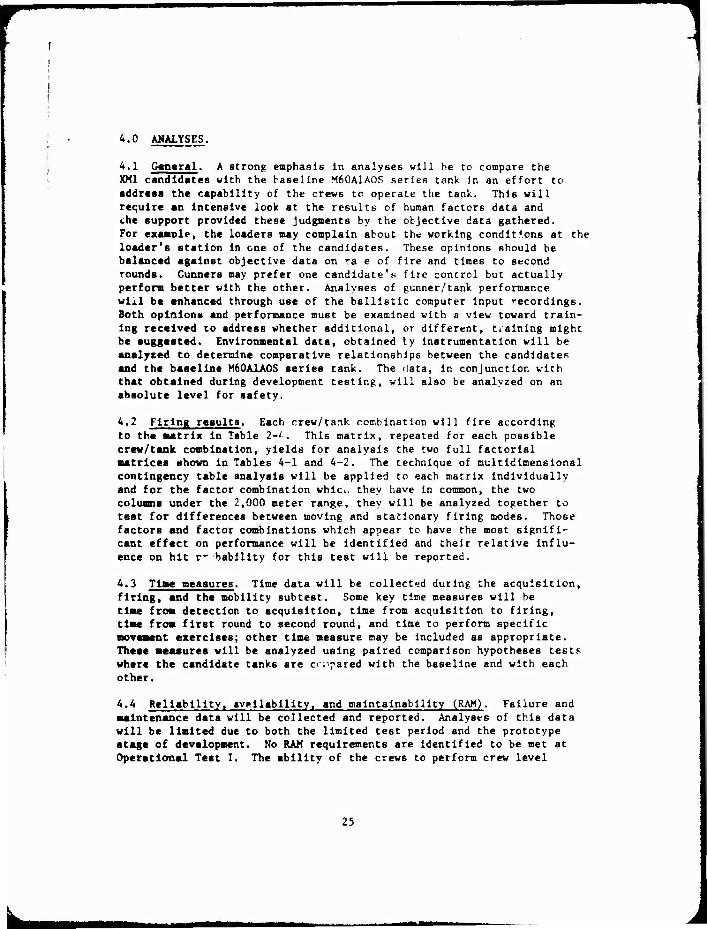
4.0 AMALYSES.
4.1 General^ A strong emphasis In analyses will be to compare the XM1 candidates with the baseline M60A1AOS series tank in an effort to addrtaa the capability of the crews to operate the tank. This will require an intensive look at the results of human factors data and ehe support provided these Judgments by the objective data gathered. For examole, the loaders may complain about the working conditions at the loader's station In one of the candidates. These opinions should be balanced against objective data on ra e of fire and times to second rounds. Gunners may prefer one candidate's fire control but actually perform better with the other. Analyses of gunner/tank performance will be enhanced through use of the ballistic computer input recordings. Both opinion« and performance must be examined with a view toward train- ing received co address whether additional, or different, training might be suggested. Environmental data, obtained ty instrumentation will be analyzed to determine comparative relationships between the candidates and the baseline M60A1AOS series tank. The data, in conjunction with that obtained during development testing, will also be analyzed on an abaolute level for safety.
4.2 Firing results. Each crew/tank combination will fire according
to the aatrlx In Table 2-'. This matrix, repeated for each possible crew/tank combination, yields for analysis the two full factorial matrices shown In Tables 4-1 and 4-2. The technique of multidimensional contingency table analysis will be applied to each matrix individually and for the factor combination whlci. they have In common, the two columns under the 2,000 meter range, they will be analyzed together to teat for differences between moving and stationary firing modes. Those factors and factor combinations which appear to have the most signifi- cant effect on performance will be identified and their relative influ-
ence on hit r" bablllty for this test will be reported.
4.3 Time measures■ Time data will be collected during the acquisition, firing, and the mobility subtest. Some key time measures will be time from detection to acquisition, time from acquisition to firing, time from first round to second round, and time to perform specific movement exercises; other time measure may be included as appropriate. These measurea will be analyzed using paired comparison hypotheses tests where the candidate tanks are cr,'pared with the baseline and with each
other.
4.4 Reliability, avallablllty, and maintainability (RAM). Failure and maintenance data will be collected and reported. Analyses of this data will be limited due to both the limited test period and the prototype stage of development. No RAM requirements are identified to be met at Operational Test I. The ability of the crews to perform crew level
25

=1 maintenance will be examined and any higher level maintenance performed by the contractor will be observed. Any difficulties encountered or potential problem areas will be reported.
4.5 Gunaight camera. Gunslght camen film analyses Is to concentrate on sight picture and smoothness of tracking. In the target acquisition nonflring phase, the film is to be used to confirm gunner lay at time of simulated firing to ensure that the time froni initial acquisition to final lay is valid.
26

1
TABLE 4-1. MATRIX FOR ANALYSES OF MAIN GUN FIRINGS FROM MOVING TANK
Tank/ crew No,
Target mode
Nominal range (meters) 1 and MiBimnltior type |
| 500 1,500 ! 2,con |
H A H A H A
fttO/
1.2
S
M
M60/
4.5
S
M
M60/
3.6
S
M
GM/
1.2
S
M
GM/
4.5
S
M
CHR/
1.2
S
M
CHR/
3,6
S
M 1 H-HEAT-TP-T; A-APDS-T. Crtws 1&2 trained on M60A1AOS, Chrysler, GM. Crews 4&5 trained on M60A1A0S, GM. Crews 3&6 trained on M60A1A0S, Chrysler.
27

^
TABLE 4-2. MATRIX FOR ANALYSES OF MAIN GUN FIRINGS FROM STATIONARY TANK
Tank/ crew No.
Target mode
Nominal range (meters) and aanunltlon type 2,000 2,500
H A H A j M60/
1.2
S
M | 1
M60/
4.5
S
M
M60/
\6
S i
M
GM/
1.2
S
M
GM/
«.5
S 1
M 1
CHR/
1.2
S 1 M
I ( 1
CHR/
3.6
S
M i
H-HEAT-TP-T; A-APDS-T. Crews 1&2 trained on M6ÜA1AOS, Chrysler, GM. Crews 4&5 trained on M60A1AOS, GM. Crews 35.6 trained on M60A1AOS, Chrysler.
28

1
>
5.0 RESOURCES REQUIRED. To Implement this test design the resources listed in Tables 5-1 through 5-4 will be required.
TABLE 5-1. VEHICLES
[Quantity Item
M60A1AOS baseline tank.
XM1 prototype from each candidate.
XM1 automotive test rig from each candidate.
Threat tank, (T62 or M60).
Threat APC, (BMP or M113).
Threat ATGM, (bAGGER, SS-11, or ground mounted tow).
Scout helicopter,
5-ton wrecker.
M88 VTR.
GOER 8-ton wrecker.
Tank transporter.
AVLB.
MSI
TABLE 5-2. TARGETS
Item
Front silhouettes of T64.
Side silhouettes of T64,
Turret sillhouettes of T64.
"E" silhouettes for machineg.m engagements.
29
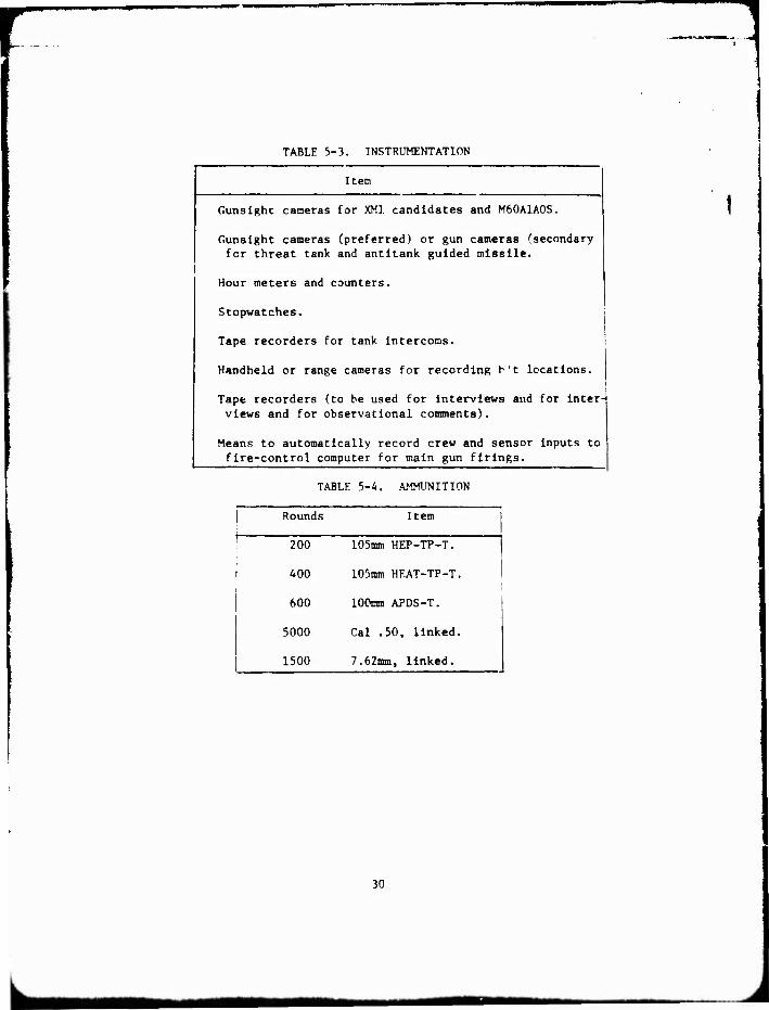
TABLE 5-3. INSTRUMENTATION
Item
Gunslghc cameras for XM1 candidates and M60A1A0S.
Gunslght cameras (preferred) or gun cameras (secondary for threat tank and antitank guided missile.
Hour meters and counters.
Stopwatches.
Tape recorders for tank intercoms.
Handheld or range cameras for recording h't locations.
Tape recorders (to be used for interviews and for inter-
views and for observational comments).
Means to automatically record crew and sensor inputs to fire-control computer for main gun firings.
TABLE 5-4. AMMUNITION
Rounds Item
200 105nmi HEP-TP-T.
400 105mm HEAT-TP-T.
600 100mm APDS-T.
5000 Cal .50, linked.
1500 7.62inm, linked.
30

ABRRFVIATIONS AST* ACRONYMS
1
APr
APDS
APDS-T
ASARC
ATOM
ATR
AVLB
BILI
CDEC
CHRY
DT
CM
HEAT
HEAT-TP-T
HEP
HEP-TP-T
HET
MICV
MMBF
mph
No.
OT
OTEA
PM
PV
RAM
SACCER
TIWG
VTR
armored personnel carrier armor pierclnp discarding sahot fanmur. it I on i armor piercing discarding sahot with tracer
(ammunl t ion) Armv Systc.ns Acquisition Review Council antitank guided missile automotive test rig armored vehicle launched bridge
basic issue list items
US Armv Combat Developments F.xper imentat Ion ronmanri Chrysler
development test
General Motors
high explosive antitank (ammunition) high explosive antitank, target practice with tracer (ammunition
high explosive plastic (ammunition) high explosive plastic, target practice with tracer (ammunition)
heavy equipment transporter
Mechanized Infantrv Combat Vehicle mean-miles-between-fallure miles per hour
number
operational test US Army fperational Test and Evaluation Agencv
preventive maintenance pilot vehicl»
rellabilitv, availabilitv, and maincainabilitv
antitank missile
test integration working group
vehicle, tank retriever
n
•
DEPARTMENT OF THE ARMY UNITED STATES ARMY OPERATIONAL TEST AND EVALUATION AGENCY
5600 t;OLUMBIA PIKE
FALLS CHURCH , VIRGINIA 220•1
DACS-TED-H 1 l FT9 1<176
SUBJECT: Aaend8ent to Test Design Plan, XHl OT .
SEE DISTRIBUTION
1. Reference: Test Design Plan, XHl OT I, 8 January 1976.
2. This aaendaent provides additional detail on test conditions f or the taraet acquisition phase at par~graph 3, below, adds a requirement f~ r
ltaited niaht drivina exercises at paragraph 4, expands the section on survivability to include eleMnts of a.aunitior c0111partment integrity, and provides addeJ sections to the dendritic covering data requir..ents for theae areas (lncl 1).
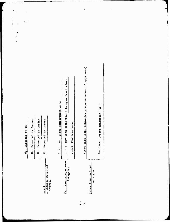
3. The taraet acquisition phase described in paraaraph 2.2.1 of reference is described her£ in additional detail. Short of actually firing, the acquisition exercises will cover all aspects of vehic l e fi&htability and interactions between crev ~era. The phase ai&ht better be described as a "fi&htability plwse", of which target acquisition is a major part. Tactical co-.nications should be simulated durin& the acquisition phase with the controller takin& the part of the platoon leader or ca.pany ca..ander. This will require the ca.aander of the tested tank to perform duties and interact in • aaaner that would be expected in a unit operation. All crev aeabers are to perfora their norully required duties during the st.ulated enaaaeaents; du.ay rounds are to be provided for the loader. In the closed and open hatch aodes (see Table 2-2 of reference), one of the taraets should be available for acquisition at a ranae beyond 2,000 meters, with a ranae of 2,500 to 3,000 aeters preferred, if practical at the test s H e. Additionally , each crev/tank combination should be presented with r i • ~tiona portrayina aultiple targets. These should be set up so that at a particular locat~on alona the C'-· ":o:se three or 80r• targets becOM available for acquisition in sequence while the previous taraet is still being en&aaed. These exercise.s will perait loadin& under 80re severe conditions of 80v...at and terrain than can be expected durin& actual live fire (because of safety constraints). These conditions will add to the human factors data concernin& the loader's station and aay provide useful additional objective data on tiaes to reload (see dendritic 1.1.4 at Inclosure).

DACS-TED-M
SUBJECT: Amendment to Tesi 2^aign Plan, XM1 OT I
The objective data ;n tlm»o t» load will be constrained because of the lack of automatic round extraction. Fcr these dry-fire exercises the breech Is to be open prior to start of the engagement; times to be gathered are to represent time to load the second round of the engagement. The time line for loading is to start with the Tank Commander's announcement of type of amunltion to be used for the engagement and Is to end with the loader's announceoent that the round has been loaded. These tiv.ee shocld be care- fully compared with times to load during live firing to ensure that the necessary conditions during dry fire have not affectec* the validity of the times.
4. Night driving exercises are to be conducted with each crau/tank com- bination. The AN/WS-2 Night Vision Driver's Viewer will eventually be incorporated in the XM1; it is not available for OT I however, and these exercises will therefore be of a degraded mode operation. The driver will have no visual augmentation device; the tank cenmander will have the AN/WS-5 "Cav-Nav" goggles that a "e standard in the TOE. Two types of exercises will be run; the first will entail a convoy simulation with the tanks following a lead vehicle which has the "cat-eye" tall lights on. This will be run on improved or secondary roads and will be about five miles in length. The second exercise will be cross-country, will be 1,500 to 2,000 meters in length, and will not be following another vehicle. Safety is a paramount consideration in the night driving. Controllers should be equipped with adequate night vision devices so the exercises can be monitored. Ambient light levels should be as similar as possible for comparison runs, suggesting that all the runs be conducted in a sln.'.lc night or that all convoy runs be done in one night and all cross-country runs be done during a second night.
5. Under survivablllty, one additional area of Interest is added covering the problems encountered in maln;ainlng the Integrity of ananunltlon compart- mentallzatlon while operating the XM1 prototypes, especially while firing the main gun. The number of times the compartment Is open, the duration of each occurrence, and any observed problems wlii. be noted r.r.d recorded.
6. This amendment together with the basic test design will be used as the Teat Design Plan for the Leopard AV testing scheduled for this fall. The test activity schedule will be modified to reflect the two tanks (Leopard AV and M60A1A0S) that will be used rather than the three tanks, but all test activities for the Leopard AV w' ^ be the same a* for the Chrysler and General Motors XM1 prototypes.
FOR THE COMMANDER.
1 Incl as
^RICHARD B. MAJOR Sj LTC, GS Executive Officer
DACS-TED-M SUBJECT: Amendment to Test Design Plan, XM1 OT I
DISTRIBUTION: HQDA
SAUS-OR DAMO-RQD DAMA-WSW
COMMANDERS: TRADOC, ATTN: DARCOM, ATTN: FORSCOM, ATTN USACAA, ATTN: USALEA, ATTN: TECOM, ATTN: USALOGC, ATTN; USAACS, ATTN:
ATCD-TM, Fort Monroe, VA 23651 AMCRD-FG, 5001 Eisenhower Ave., Alexandria, VA 22333
AFOP-DA, Fort McPherson, GA 30330 MOCA-SA-S, 8120 Woodmont Ave., Bethesda, MD 20014 DALO-LEI, New Cumberland, PA 17070
AMSTE-AR, Aberdeen Proving Ground, MD 21005 ATCL-E, Fort Lee, VA 23901
ATZK-CD, Fort Knox, KY 40121 DIRECTOR, USAMSAA, ATTN: AMXSY-GS, Aberdeen Proving Ground, MD 21005 PROJECT MANAGER, XM1 Tank System, ATTN:
Warren, MI 48092 AMCPM-GCM-ST, 28150 Dequindre,
3'/

1
0)
a H
>s V4-!
w ■H o «-I v c
ai 4J *l 5 3 11 T3 (_> o »—( <:
n 01 oc b u « » H OC
w T3 « B H O u x: it u in c
w *J 01 01 oc OC' u 4j u a 01 It! H 00 H ^1
•o a 4J B H X o u. u X ~-< 01 4J k- v. <
1 c
M «1 oc V4 «-i a 01 H 0(1
M T) a B H o o X 01 M in B
B
c a) u to •»-(
s1 •H B
■H o c
ID B V
l-t tr * u 0 c t- w
c- u a
^H ti- c M B 4J a
0 3 u X
1
5^ > B O o
_L
c • 3 f) C • U •-'
tu
CM U • B
JN «I
oo 6 >
<3
00
J
1
1 u 1 «1 '
u § 1- o ^ >s
XI JO
■o TJ ; V *
41 a
o z
V u u « S! o S --(
•I IS M b ki (I
/—s l
g ■H 4J
£ U « «1
s a a « 0 o. o w c ii
s 4J
| M 4J O U
o 41
u 0 o CJ c
CO « oo CO e a 0 §
w <-i
0 g o z X CU
<-» Csl n m m (-1
rsj r^ <N
w g B u ^ M a q . H
1 0 u
1 u c -4
<^,
^^ c 1 a 41 a >> «J
(M
0
4J c « 0 41 CJ C 3 0 a ^-■v
c • "a _3
cc r
kl «0 I 41 41 T)
u C
u § j! ki a •i a •o t- a
0 4/ s
•r-* 41 U B
u H ki q 73
CO a
■o a 0
■j G 3
0 oo u
c 41 •H
B ■H g H
•» r-i
rH
_ <^


![Title 76 RCW - Washingtonleg.wa.gov/CodeReviser/RCWArchive/Documents/2016... · (2016 Ed.) [Title 76 RCW—page 1] Title 76 Title 76 76 FORESTS AND FOREST PRODUCTS FORESTS AND FOREST](https://img.pdfslide.us/doc/110x75/5f7a85dc890c5561e6763c0c/title-76-rcw-2016-ed-title-76-rcwapage-1-title-76-title-76-76-forests-and.jpg)


![РЕПОРТАЖ - spbu.rujf.spbu.ru/upload/files/file_1411466173_6546.pdf · лат. facture — исполнение, форма] — жанр средств массовой коммуникации;](https://img.pdfslide.us/doc/110x75/60606634d0d1886ca92e100b/-spburujfspburuuploadfilesfile14114661736546pdf-.jpg)