Embed Size (px)
Citation preview

Diamond Amplifier For Photocathodes
Triveni Rao, Ilan Ben-Zvi, Andrew Burrill , Xiangyun Chang, Steven Hulbert, Peter D. Johnson and Jörg Kewisch
Brookhaven National laboratory Upton, NY 11973
Abstract. We report a new approach to the generation of high-current, high-brightness electron beams. Primary electrons are produced by a photocathode (or other means) and are accelerated to a few thousand electron-volts, then strike a specially prepared diamond window. The large Secondary Electron Yield (SEY) provides a multiplication of the number of electrons by about two orders of magnitude. The secondary electrons drift through the diamond under an electric field and emerge into the accelerating region proper of the “gun” through a Negative Electron Affinity surface of the diamond. The advantages of the new approach include the following: 1. Reduction of the required number of primary electrons by the large SEY, i.e. we can utilize a very low laser power in a photocathode producing the primaries. 2. Low thermal emittance due to the NEA surface and the rapid thermalization of the electrons.3. Protection of the cathode from possible contamination from the gun, allowing the use of large quantum efficiency but sensitive cathodes. 4. Protection of the gun from possible contamination by the cathode, allowing the use of superconducting gun cavities. 5. Production of high average currents, up to ampere class. 6. Encapsulated design, making the “load-lock” systems unnecessary. This paper presents the criteria that need to be taken into account in designing the amplifier
INTRODUCTION
The creation of high average-current, high brightness electron beams is a key enabling technology for a large number of accelerator-based systems, such as ultra-high-power Free-Electron Lasers (FELs), Energy-Recovery Linac (ERL) light sources, electron cooling of hadron accelerators, and many more.
In order to produce the high brightness (or low emittance at high bunch charge),
laser photocathode RF guns have a proven performance that makes them the ideal choice for devices like X-ray FELs. The high electric field that may be achieved in the RF gun is the key factor in getting a large charge with a small emittance.
The photocathode and its associated laser are, arguably the most difficult aspect of
the laser-photocathode electron gun. Robust, metallic cathodes are popular in RF guns that operate at a very low average current. They are usually driven in the near UV (typically 0.25 microns wavelength, obtained by frequency quadrupling a 1 micron laser). The frequency quadrupling is itself a wasteful process. Semi-conducting photocathodes can provide very high Quantum Efficiency (QE) at a longer wavelength, between 1 to 0.5 microns (IR to green light), making such cathodes the natural candidates for high average current guns. The problem with these cathodes is
178
Downloaded 25 Feb 2009 to 146.137.148.78. Redistribution subject to AIP license or copyright; see http://proceedings.aip.org/proceedings/cpcr.jsp

twofold: They are very sensitive to any contamination, thus must be prepared and maintained under ultra-high vacuum conditions and still may suffer a short lifetime if the vacuum in the gun is less than pristine. The other problem that may be encountered in superconducting guns is one in which the chemicals of the cathode (most common is cesium) may degrade the superconducting gun surface. Finally, even with the extremely good QE of 10% available in green light with such cathodes, the required properties of the CW laser are formidable, requiring a few 10’s of watts CW with exacting demands on pulse length, stability and more.
In order to produce a high average current, one has to operate the gun in a
continuous mode (CW). That is easy with a DC guns, but the price to pay is a much lower electric field. The best duty factor demonstrated so far in normal conducting RF guns is 25%. Guns with 100% duty factor are in the works, but again the field strength is sacrificed due to the huge power that flows into the gun cooling system. The best candidate for a high-brightness CW gun is the superconducting RF gun. However, the problem there is, as stated above, the contamination of the gun by the cathode material.
We have reported [1] a new approach to the generation of high-current, high-
brightness electron beams. Primary electrons are produced by a laser-photocathode (or other means, as will be discussed later), are accelerated to a few thousand electron-volts, and then strike a specially prepared diamond window. The large Secondary Electron Yield (SEY) provides a multiplication of the number of electrons by about two orders of magnitude. The secondary electrons drift through the diamond under an electric field and emerge into the accelerating region proper of the “gun” through a Negative Electron Affinity surface of the diamond. The accelerating field can be provided by the gun electrical field that penetrates the diamond window.
The advantages of the new approach include the following: 1. Reduction of the
required number of primary electrons by the large SEY, i.e. we can utilize a very low laser power in the photocathode producing the primaries. 2. Low thermal emittance due to the NEA surface and the rapid thermalization of the electrons. 3. Protection of the cathode from possible contamination from the gun, allowing the use of large quantum efficiency but sensitive cathodes. 4. Protection of the gun from possible contamination by the cathode, allowing the use of superconducting gun cavities. 5. Production of high average currents, up to ampere class. 6. Encapsulated design, making the “load-lock” systems unnecessary.
Naturally, this cathode will be most suitable for a superconducting RF gun for CW
operation, but it has significant advantages also for normal conducting, pulsed RF guns and DC guns. Therefore, in the following, we will describe the application of this new paradigm as applied to a superconducting RF gun with the primary electron source being a cesium-potassium-antimonide cathode driven by a 0.5 micron laser. Extension to other guns and other cathodes is straightforward.
179
Downloaded 25 Feb 2009 to 146.137.148.78. Redistribution subject to AIP license or copyright; see http://proceedings.aip.org/proceedings/cpcr.jsp
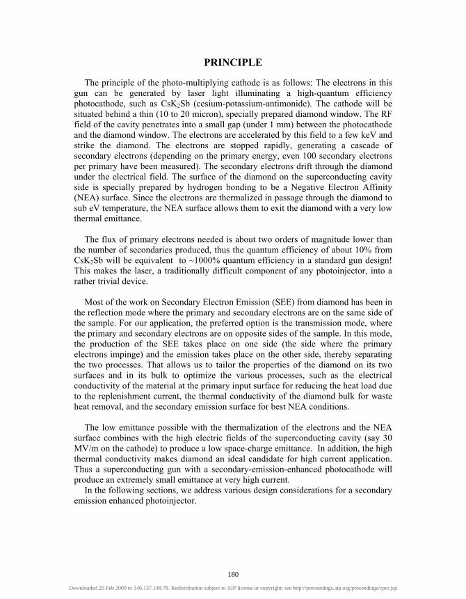
PRINCIPLE
The principle of the photo-multiplying cathode is as follows: The electrons in this gun can be generated by laser light illuminating a high-quantum efficiency photocathode, such as CsK2Sb (cesium-potassium-antimonide). The cathode will be situated behind a thin (10 to 20 micron), specially prepared diamond window. The RF field of the cavity penetrates into a small gap (under 1 mm) between the photocathode and the diamond window. The electrons are accelerated by this field to a few keV and strike the diamond. The electrons are stopped rapidly, generating a cascade of secondary electrons (depending on the primary energy, even 100 secondary electrons per primary have been measured). The secondary electrons drift through the diamond under the electrical field. The surface of the diamond on the superconducting cavity side is specially prepared by hydrogen bonding to be a Negative Electron Affinity (NEA) surface. Since the electrons are thermalized in passage through the diamond to sub eV temperature, the NEA surface allows them to exit the diamond with a very low thermal emittance.
The flux of primary electrons needed is about two orders of magnitude lower than
the number of secondaries produced, thus the quantum efficiency of about 10% from CsK2Sb will be equivalent to ~1000% quantum efficiency in a standard gun design! This makes the laser, a traditionally difficult component of any photoinjector, into a rather trivial device.
Most of the work on Secondary Electron Emission (SEE) from diamond has been in
the reflection mode where the primary and secondary electrons are on the same side of the sample. For our application, the preferred option is the transmission mode, where the primary and secondary electrons are on opposite sides of the sample. In this mode, the production of the SEE takes place on one side (the side where the primary electrons impinge) and the emission takes place on the other side, thereby separating the two processes. That allows us to tailor the properties of the diamond on its two surfaces and in its bulk to optimize the various processes, such as the electrical conductivity of the material at the primary input surface for reducing the heat load due to the replenishment current, the thermal conductivity of the diamond bulk for waste heat removal, and the secondary emission surface for best NEA conditions.
The low emittance possible with the thermalization of the electrons and the NEA
surface combines with the high electric fields of the superconducting cavity (say 30 MV/m on the cathode) to produce a low space-charge emittance. In addition, the high thermal conductivity makes diamond an ideal candidate for high current application. Thus a superconducting gun with a secondary-emission-enhanced photocathode will produce an extremely small emittance at very high current.
In the following sections, we address various design considerations for a secondary emission enhanced photoinjector.
180
Downloaded 25 Feb 2009 to 146.137.148.78. Redistribution subject to AIP license or copyright; see http://proceedings.aip.org/proceedings/cpcr.jsp

THE STRUCTURE OF THE DIAMOND AMPLIFIER
There are many possible configurations for amplifying the current using secondary emission. The basic principle is as follows: (1) primary electrons strike the backside of a diamond window at an energy of a few keV, producing a large number of secondary electrons in the diamond; (2) the secondary electrons are transported across the diamond by a superimposed electric field, and (3) the electrons emerge into the gun accelerating gap. Indeed, one can use this scheme to enhance any electron source for primary electrons, including a pulsed thermionic electron source or even an X-ray source. The process of conversion of the primary electrons into secondary electrons wipes out the history of the primary electrons, leaving only a few characteristics: The current and bunch length of the primaries and the area of the diamond over which they are spread. Thus, for example, the emittance of the primary electrons is unimportant. Indeed, one can even cascade a few diamond secondary emission enhancing plates and use the output of one as the input to the next, increasing dramatically the current gain of the combined device. Such a cascaded secondary emission enhanced cathode can use a low power laser with a rugged but low quantum efficiency metallic cathode as the initial source of the primary electrons. However, for the sake of the discussion, we will assume that the source of the primary electrons is a photocathode illuminated by a laser pulse and that only a single stage of diamond secondary emission enhancer is used.
Likewise, the diamond secondary-emission-enhanced photocathode can be placed
in either a DC electron gun or RF electron gun. The RF electron gun can be either a pulsed or CW device, normal-conducting or superconducting. Again, for the sake of the discussion we will assume a CW superconducting RF gun operating at 703.75 MHz. These parameters happen to be the parameters for the electron gun for the RHIC electron cooler.
Figure 1a-c shows a schematic layout of such a device. The primary electrons
originate in a photocathode, illuminated by a laser beam. Part of the cavity of the RF gun is shown. The cathode is mounted on a cathode stalk, which is thermally insulated from the gun cavity. For our example of a superconducting gun cavity the stalk may be cooled to liquid nitrogen temperature. A choke joint (not shown) provides electric continuity to the gun cavity and prevents leakage of RF field through the cathode stalk.
The electric field of the gun cavity penetrates the diamond and terminates on the
photocathode. This field is quite high, of the order of 10 to 20 MV/m at the launch phase of the electrons from the photocathode (corresponding to about 30 MV/m peak field). Thus, a gap of 0.5 mm between the photocathode and the diamond will provide 5-10 keV primary electrons at the time they strike the diamond.
An enlarged section of the diamond is shown in Figure 1c. The diamond face
accepting the primary electrons is coated with a very thin layer of gold. The purpose of the gold is to serve as an electric conductor to bring the current for replenishing the
181
Downloaded 25 Feb 2009 to 146.137.148.78. Redistribution subject to AIP license or copyright; see http://proceedings.aip.org/proceedings/cpcr.jsp

diamond with the current that it emits. The gold is thin enough to be transparent toboth the laser radiation and the cavity electric field. The secondary electrons aregenerated in the diamond window. Finally, the diamond face on the gun cavity sidehas the diamond dangling bonds terminated by hydrogen to provide a NegativeElectron Affinity (NBA) surface. This serves to ease the secondary electron's exit intothe gun cavity.
FIGURE 1. Schematic diagram of a secondary-emission-enhanced photoinjector. Figure la shows thecathode insert in the gun cavity. Figure Ib is a magnified view of the cathode insert. The gap betweenthe diamond window and the photocathode is typically about a millimeter. Figure Ic is acloseup view ofthe diamond, showing, schematically, a gold coating on the photocathode side of the diamond andhydrogen termination of the diamond's dangling bonds on the gun side of the diamond. The gold isvery thin, while the diamond may be as much as 10 microns thick, and the hydrogen terminationthickness is a monolayer.
The physical and electronic properties of diamond make it a very attractivecandidate for a high current, and high current density, secondary electron emitter to beused in an RF injector. Some of these properties are:
Diamond has the highest high electric field electron and hole velocity [2] of>107 cm/s at 2 MV/m field, a gradient that would be present in an RF injector. Such a
182
Downloaded 25 Feb 2009 to 146.137.148.78. Redistribution subject to AIP license or copyright; see http://proceedings.aip.org/proceedings/cpcr.jsp

high velocity decreases the transit time of the secondary electrons through the medium.
· Diamond has the ability to be doped to desired boron concentration and hence desired electrical resistivity, low trap density and high carrier mobility
· Hydrogenated, boron-doped as well as undoped diamond has shown to have negative electron affinity,[3, 4] increasing the secondary electron yield. Indeed, boron-doped, hydrogenated polycrystalline diamond has been shown [5] to be an effective secondary emitter with an enhancement factor of > 80.
· The energy distribution of the secondary electrons under low electric field is shown to be < 1 eV, centered ~ 4.5 eV above the Fermi energy. This energy distribution is larger than the thermal distribution of the electrons, leading one to conclude that the escape time is smaller [6] than the electron-phonon relaxation time of 10-12-10-13 s [7]. The energy distribution of secondary electrons traversing the diamond will be the result of an equilibrium: On one hand, the electric field pumps energy into the electrons and the elastic collisions randomize this energy. On the other hand, the inelastic collisions remove thermal energy from the electrons and they tend towards the lattice temperature. This process is calculated below, and results a low electron temperature of about 0.1 eV and a temporal width of ~1 ps, or with a slightly larger energy distribution, but narrower temporal width. In either case, the brightness of these electrons will be very high.
· Transport of low energy electrons through diamond has been shown to be very efficient [8]
· The thermal conductivity of diamond is in the range of 20 W/cmK at room temperature and even higher at LN2 temperature [9]. Dissipation of heat generated by the high current of high-energy electrons becomes manageable with such high conductivity.
In the following, we will utilize the physical properties of diamond to calculate various parameters of the secondary electron beam.
Secondary Electron Temperature
The electron temperature is determined by the energy of the electrons at birth and the equilibrium energy acquired during transit to the surface due to inelastic scattering experienced by the electrons. As mentioned previously, the electron energy at birth has been measured to be << 1 eV and can be as low as 0.1 eV. The Inelastic Mean Free Path (IMFP) of the electrons in the diamond and the acceleration by the electric field determine the equilibrium temperature attained by the drifting electrons. Since the IMFP is energy dependent, we must solve for the temperature and the inelastic mean free path simultaneously. The equation for the equilibrium electron random energy Ee as a function of the inelastic mean free path λi, the lattice temperature Ti, and the electric field E in the diamond can be written as follows:
e ld
w
E kT eEVτ− = − ,
(1)
183
Downloaded 25 Feb 2009 to 146.137.148.78. Redistribution subject to AIP license or copyright; see http://proceedings.aip.org/proceedings/cpcr.jsp

where k is the Boltzmann constant, e is the electron’s charge, Vd is the drift velocity and τw is the relaxation time of the electron’s temperature to the lattice. The thermal drift velocity at room temperature is known to be about 105 m/s for both pure and boron-doped diamond. At fields of the order of a few MV/m, the drift velocity at room temperature is approximately 2x10⁵ m/s. Data at room temperature were fitted to a straight line result Vd = 105 (0.2E + 0.55) , (2) where Vd is the drift velocity in m/s and E is the instantaneous electric field in the diamond in MV/m. This is just an approximation over a limited range of electric field, ~1 to 2 MV/m, which is sufficient for our present purpose. Neglecting the lattice temperature, and expressing the relaxation time as a function of the electron’s thermal energy and the IMFP, we get
312 e d imV eEV λ= −
(3)
For the IMFP, we will use the semi-empirical formula of M.P. Seah and W.A. Dench [10]
( )1
2 2538 0.41i r m r mE a E aλ − = + ,
(4)
where am is the thickness of a monolayer in nanometers. For diamond, am= 0.1783 nm. Er is the electron’s energy above the Fermi level. At the low energies near equilibrium, the first term dominates. Expressing the energy above the Fermi level as
r eE E= + ∆ , (5) where ∆=EC-EF is the energy of the conduction band above the Fermi energy, we can solve numerically equations (3) and (4). We will use the following values: a band gap of 5.5 eV and the Fermi energy is 2.725 eV below the conduction band. Thus ∆ = 2.775 eV. The solution of the equations above for a field E of 2 MV/m results in Ee=0.1eV, a comfortably low temperature. The corresponding IMFP is λi =11.6 nm. The maximum energy that the electron can gain during one IMFP is eEλi, which is 0.023 eV.
Transit Time and Temporal Spread
The transit time of the electrons must be considered in an RF gun application, since this transit time appears as a delay between the arrival time of the primary electrons and the emergence of the secondary electrons into the gun. During this time the phase of the RF field is advancing and the various calculations must take this time dependence into account.
184
Downloaded 25 Feb 2009 to 146.137.148.78. Redistribution subject to AIP license or copyright; see http://proceedings.aip.org/proceedings/cpcr.jsp

For the known drift velocity of 1.5x10⁵ m/s, the time of flight through a 10 micron thick diamond window is 66 ps, or about 17 degrees of phase at 703.75 MHz, a reasonable number. In fact, the mobility of electrons increases with lowered temperature, and that may reduce the flight time by a factor of 2 if the diamond temperature is reduced from 300°K to about 100°K (the mobility at low field increases more dramatically with lowered temperature, but at a few megavolts per meter the increase is smaller). Another important consideration is the spread in the time of arrival of the secondary electrons at the far side of the diamond window. Most applications of electron guns place an upper limit on the final pulse width. There are two mechanisms that have to be considered. The temporal spread can come from two sources. One is the random walk due to the thermal energy; the other is the space-charge-induced bunch spread. In the random walk part of the problem, the mean free path of the electrons must be considered. At very low energy most of the momentum modification of electrons takes place through elastic collisions. The elastic cross-section can be estimated by Mott’s formula, the total cross-section of electrons under 10eV is about σ=10-15 cm2. The number of elastic collisions is about:
53
1076.1 ×=×=ALNela σ
(6)
where L is the diamond thickness and A=0.178 nm is the atom radius of diamond. If one assumes that after ten elastic collisions the momentum is randomized, then the number of times that the electron may be stopped by elastic collision is about:
41076.1)( ×=elaNstop (7) The number of inelastic collisions is about:
800/)( ≈= iLineNstop λ (8) So, the number of times that electrons may be stopped by inelastic collisions can be ignored. The broadening is about:
7.0)(/)/()(/ ≈≈≈∆ elaNVLelaNTT stopdstop ps. (9)
Thus, the broadening due to thermal random walk of the electrons can be assumed negligible. Space -charge induces the main temporal spread that must be considered. The part that is different from what takes place in any high-bunch charge electron gun is that the electrons spend a period of time in the diamond, moving at a relatively low velocity. At the same time, the space charge fields are reduced by the dielectric constant of diamond, which is 7.5=rε . The geometry of the diamond window facilitates the calculation, since the electrons are spread over a very thin, wide disk. A precise calculation should take into account the time dependence of the RF accelerating field, but for a rough estimate, the field can be assumed constant (E=2 MV/m in the diamond, e.g, corresponding to 27.5 ×=Erε MV/m external field).
185
Downloaded 25 Feb 2009 to 146.137.148.78. Redistribution subject to AIP license or copyright; see http://proceedings.aip.org/proceedings/cpcr.jsp

For the R=5 mm cathode radius, at a charge of Q=1 nC per bunch, the space charge electric field acting on either end of the bunch on account of the bunch-charge is
rsc R
QEεεπ 0
2= (10)
or about 0.25 MV/m. Thus the head of the bunch will move under a field of 2.25 MV/m and the tail will move under a field of 1.75 MV/m. Now equation (1) can be used to calculate the resulting drift velocities of the head and tail, and the resulting time of flight. It can be found that, for room temperature, the head of the bunch will leave the diamond 10 ps ahead of the tail, in addition to the original bunch spread. At 703.75 MHz, this amounts to about 2.5 degrees. At 100°K, the effect is reduced to a totally negligible sub-degree spread.
Thermal Load On The Diamond
Heat is generated by a number of sources: the energy deposited by the primary electrons; the current flowing through the gold electrode to replenish the escaped charge; and the heat developed by the transit of the secondaries through the diamond.
These heat sources are evaluated and the temperature rise of the diamond is estimated here, assuming it is cooled on the periphery to near liquid nitrogen temperature.
The primary electrons’ heat load is indicated herein as Pp. Given that the secondary emission yield is approximately proportional to the primary energy, the heat generated by the primary electrons is nearly independent of their energy and depends only on the secondary electron current. Using the data for hydrogen terminated diamond, [8] the secondary emission coefficient δ is 60 at Ep=3 keV primary energy. Let the primary current be Ip and the secondary current Is, then
p
ssp E
III
50==
δ,
(11)
and therefore,
sppp IEIP 50== (12) For example, at a secondary current of 0.5 amperes, the primary electron heat load
is 25 watts. The heat load developed by the secondary electron current flowing through the
diamond can be calculated very simply by
dttVtEIP dr
t
tss
f
i
)()(ε∫=
(13)
186
Downloaded 25 Feb 2009 to 146.137.148.78. Redistribution subject to AIP license or copyright; see http://proceedings.aip.org/proceedings/cpcr.jsp

where E(t) is the gun electric field at time t, 7.5=rε is the dielectric constant of
diamond and Vd is the drift velocity of the electrons, which acquires a time dependence through its dependence on the field strength. If the peak electric field in the gun (on the cathode) is 30 MV/m, a secondary phase of emission from the diamond is 30 degrees, the thickness of diamond is 10 microns, the drift velocity is as described above, and a secondary current of 0.5 amperes is assumed, the secondary electron heat load (calculated by integrating over the time dependence of the field) is about 17 watts.
The temperature rise can be calculated given the dependence of the thermal conductivity on temperature [11]. In order to obtain a rough estimate of the temperature increase in diamond, the thermal conductivity coefficient k (in units of W/m°K) can be approximated in the temperature range of 100°K to 300°K as
TTk 4014000~)( − (14)
Assuming that the edge of the diamond is at Te=100°K, and that the temperature
rise is not bigger than 100°K, then we can integrate the temperature change across the diamond and get approximately
( )t
PTTe π4~6014000 ∆−
(15)
or
42~102.3 4 tPT
π×=∆ °K,
(16)
where P is the total power deposited, which for our example is 42 watts. The result
justifies the linear dependence of k on T assumed above. It shows that the excellent thermal conductivity of the diamond results in a negligible temperature rise in the diamond window.
Increasing the thickness of the diamond improves the cooling and does not change
Pp. The cooling and Ps are proportional to the diamond thickness. Thus, as long as Pp does not become negligible, the temperature rise at the center of the window will decrease with increasing thickness, tending to about 11°K. To estimate the worst possible case, thermal conductivity value for the whole diamond was taken as 1000 W/m°K. This results in a temperature rise (center to edge) of 290 degrees, which is still quite comfortable.
EXPERIMENTAL PROGRAM
Investigation of the performance of diamond as a secondary emitter at cryogenic temperatures in transmission mode in the presence of high accelerating electric field is
187
Downloaded 25 Feb 2009 to 146.137.148.78. Redistribution subject to AIP license or copyright; see http://proceedings.aip.org/proceedings/cpcr.jsp

critical to the design optimization of this approach. Studies of secondary emission from diamond in transmission mode [12] in very low extraction field are encouraging, but these results need to be confirmed for fields in the range of 5-10 MV/m. Transit time and temporal spread of secondary electrons, which are critical to the RF injector performance as well as to the ability to emit and transport average current of ~ 1 A, have to be measured. In order to address these issues, two parallel paths are being pursued: measurements under DC bias and measurements in a superconducting RF cavity. A description of the devices and results of preliminary measurements are described in the following sections.
DC System:
A photograph of the DC system is shown in Figure 2. It consists of ultrahigh vacuum system with a base pressure of low 10-9 Torr that houses an electron gun and a double-pass CMA [ref Physical Electronics] for generating and analyzing the energy of the secondary electrons.
Figure2 Photograph of the DC measurement system showing the electron gun and the energy analyzer The sample is electrically isolated from and physically held between isolated
parallel conductors that can be biased up to 5 kV. Grids mounted on these conductors allow the transmission of primary and secondary electrons as well as the laser beam for measurements where the primary electrons are generated by photoemission. This assembly is mounted on an adjustable manipulator for precise positioning of the sample in front of the electron gun and the energy analyzer. The sample can be cooled to ~ 80 K by flowing LN2 through this manipulator. A computer controlled data
E gun & energy analyzer
188
Downloaded 25 Feb 2009 to 146.137.148.78. Redistribution subject to AIP license or copyright; see http://proceedings.aip.org/proceedings/cpcr.jsp

acquisition system controls the energy of the primary electrons from the gun andmeasures the energy spread of the secondary electrons emitted. A short pulse UV laserbeam will be used for generating short bursts of primary electrons for transit time andtemporal spread measurements.
Single and poly crystalline samples with and without boron doping will be testedfor secondary emission. Figure 3 shows a polycrystalline sample etched using asolution of KC1O4 in aqua-regia to remove graphite inclusions from the surface. Thesurface of the sample will be hydrogenated by exposing it to 1x10"6 Torr of hydrogenin the presence of a W tip heated to 800 C for 20 minutes. The hydrogenation of thediamond lowers its work function to make it a negative electron affinity surface.
Figure 3 Polycrystalline diamond before and after being etched with KC1O4 in Aqua Regia
Preparations are underway to measure the secondary electron yield and energydistribution in the transmission mode as a function of applied field, temperature andcurrent. The transit time and temporal delay will be measured subsequently. We aremodifying an existing superconducting RF cavity at 1.3 GHz to accept a choke jointwith Nb, Nb and diamond or CsK^Sb and diamond at its tip. With such a choke joint,the efficacy of diamond as a current amplifier in the presence of high field, atcryogenic temperature, for high currents and low emittance can be tested against otherphotocathodes.
CONCLUSIONS
Diamond shows great promise as a current amplifier for photocathodes in highcurrent applications. Experiments are underway to establish the design criteria togenerate average currents of ~ 1 A using 1.5, 1.3 and 0.7 GHz RF injectors.
189
Downloaded 25 Feb 2009 to 146.137.148.78. Redistribution subject to AIP license or copyright; see http://proceedings.aip.org/proceedings/cpcr.jsp

ACKNOWLEDGMENTS
The authors would like to acknowledge superb technical assistance of F. Loeb, J. Walsh and M. Montemagno. This work supported by the U.S. DOE. under contract number DE-AC02-98CH10886.
REFERENCES
1. I. Ben-Zvi et al., C-AD Accelerator Physics Report C-A/AP/149, BNL, April 2004, http://www.agsrhichome.bnl.gov/AP/ap_notes/ap_note_149.pdf. 2. M. N. Yoder in Applications of Diamond Films and related materials, edited by Y. Tzeng et al.,
(Elsevier, NY 1991) , page 289 3. L. Krainsky, V. M. Asnin, J. A Dayton, Appl. Surface Sc. 111, 265 (1997) 4. A. Hoffman et al., J. Appl. Phys. 91, 4726 (2002) 5. A. Shih et al. J. Appl. Phys. 82, 1860 (1997) 6. L. L. Krainsky et al. Phys. Rev. B 53, R7650 (1996) 7. E. M. Conwell, High Field Transport in Semiconductors (Academic Press, NY, 1967) 8. J. E. Yater, A. Shih, R. Abrams, Phys. Rev. B 56, R4410 (1997) 9. E. Worner et al. Diamond and Related Materials, 12, 744 (2003) 10. M. P. Seah and W. A. Dench, Surf. Interface Anal. 1, pg 10 (1979) 11. D.G. Onn et al. Phys. Rev. Lett. 68 No. 18, 2806 (1992) 12. J. E. Yater, A. shih, J .E. Butler, P. E. Pehrsson, J. Appl. Phys. 93, 3082 (2003)
190
Downloaded 25 Feb 2009 to 146.137.148.78. Redistribution subject to AIP license or copyright; see http://proceedings.aip.org/proceedings/cpcr.jsp