Embed Size (px)
Citation preview
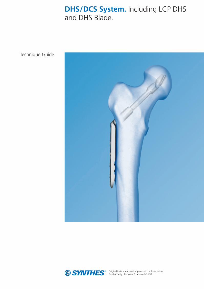
DHS/DCS System. Including LCP DHSand DHS Blade.
Technique Guide
0X6.000.255_AB.qxp:0X6.000.255_AB 04.12.2008 14:32 Uhr Seite Cvr1

0X6.000.255_AB.qxp:0X6.000.255_AB 04.12.2008 14:32 Uhr Seite Cvr2
Synthes 1
WarningThis description is not sufficient for immediate application ofthe instrumentation. Instruction by a surgeon experienced inhandling this instrumentation is highly recommended.
Table of Contents
Image intensifier control
Introduction
Surgical Technique
Product Information
Bibliography 45
System Overview 2
Features and Benefits 4
Indications and Contraindications 6
Clinical Cases 8
DHS Implantation 10
DHS Removal 24
LTSP Implantation 26
LTSP Removal 31
DCS Implantation 32
DCS Removal 36
Implants 37
Sets 43
0X6.000.255_AB.qxp:0X6.000.255_AB 04.12.2008 14:32 Uhr Seite 1
2 Synthes DHS/DCS System Technique Guide
System Overview
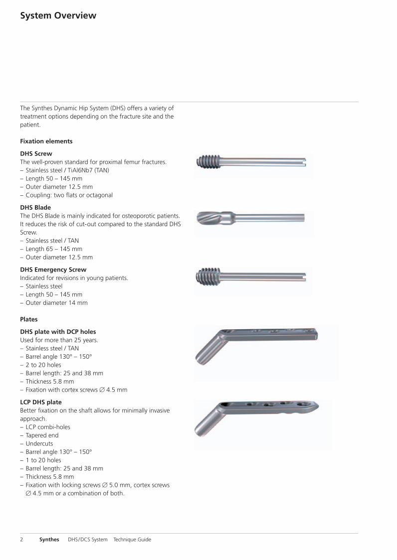
The Synthes Dynamic Hip System (DHS) offers a variety oftreatment options depending on the fracture site and the patient.
Fixation elements
DHS ScrewThe well-proven standard for proximal femur fractures.– Stainless steel / TiAl6Nb7 (TAN)– Length 50 – 145 mm– Outer diameter 12.5 mm– Coupling: two flats or octagonal
DHS BladeThe DHS Blade is mainly indicated for osteoporotic patients.It reduces the risk of cut-out compared to the standard DHSScrew. – Stainless steel / TAN– Length 65 – 145 mm– Outer diameter 12.5 mm
DHS Emergency ScrewIndicated for revisions in young patients.– Stainless steel – Length 50 – 145 mm– Outer diameter 14 mm
Plates
DHS plate with DCP holesUsed for more than 25 years.– Stainless steel / TAN– Barrel angle 130° – 150° – 2 to 20 holes – Barrel length: 25 and 38 mm– Thickness 5.8 mm – Fixation with cortex screws � 4.5 mm
LCP DHS plateBetter fixation on the shaft allows for minimally invasive approach. – LCP combi-holes– Tapered end– Undercuts– Barrel angle 130° – 150° – 1 to 20 holes – Barrel length: 25 and 38 mm– Thickness 5.8 mm– Fixation with locking screws � 5.0 mm, cortex screws
� 4.5 mm or a combination of both.
0X6.000.255_AB.qxp:0X6.000.255_AB 04.12.2008 14:32 Uhr Seite 2
Synthes 3
DHS Trochanter Stabilizing Plate
All DHS Trochanter Stabilizing Plates can be used with theconventional DHS or the LCP DHS plate.
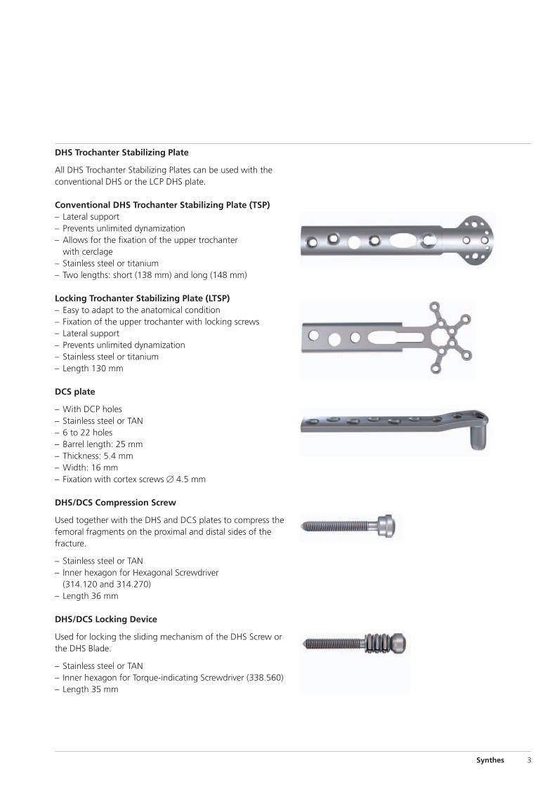
Conventional DHS Trochanter Stabilizing Plate (TSP)– Lateral support– Prevents unlimited dynamization– Allows for the fixation of the upper trochanter
with cerclage– Stainless steel or titanium– Two lengths: short (138 mm) and long (148 mm)
Locking Trochanter Stabilizing Plate (LTSP)– Easy to adapt to the anatomical condition– Fixation of the upper trochanter with locking screws– Lateral support– Prevents unlimited dynamization– Stainless steel or titanium– Length 130 mm
DCS plate
– With DCP holes– Stainless steel or TAN– 6 to 22 holes– Barrel length: 25 mm– Thickness: 5.4 mm– Width: 16 mm – Fixation with cortex screws � 4.5 mm
DHS/DCS Compression Screw
Used together with the DHS and DCS plates to compress thefemoral fragments on the proximal and distal sides of thefracture.
– Stainless steel or TAN– Inner hexagon for Hexagonal Screwdriver
(314.120 and 314.270)– Length 36 mm
DHS/DCS Locking Device
Used for locking the sliding mechanism of the DHS Screw orthe DHS Blade.
– Stainless steel or TAN– Inner hexagon for Torque-indicating Screwdriver (338.560)– Length 35 mm
0X6.000.255_AB.qxp:0X6.000.255_AB 04.12.2008 14:32 Uhr Seite 3
4 Synthes DHS/DCS System Technique Guide
DHS System. The appropriate solutionfor proximal femoral fractures.
Modular System
The Dynamic Hip System (DHS) from Synthes consists of thefollowing options:– DHS Screw or DHS Blade– Standard plates or LCP plates– Locking Trochanter Stabilizing Plate (LTSP)
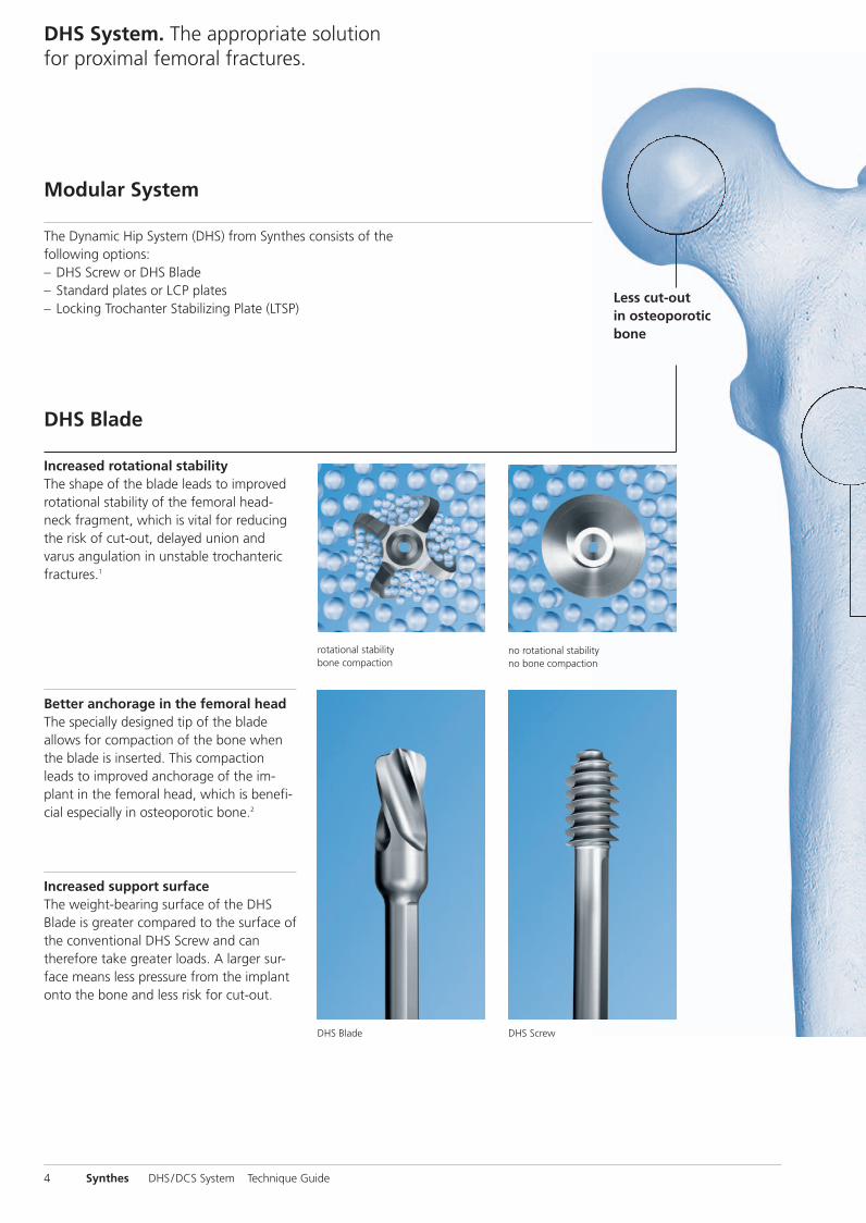
Less cut-out in osteoporoticbone
DHS Blade
Better anchorage in the femoral headThe specially designed tip of the blade allows for compaction of the bone whenthe blade is inserted. This compactionleads to improved anchorage of the im-plant in the femoral head, which is benefi-cial especially in osteoporotic bone.2
Increased support surfaceThe weight-bearing surface of the DHSBlade is greater compared to the surface ofthe conventional DHS Screw and cantherefore take greater loads. A larger sur-face means less pressure from the implantonto the bone and less risk for cut-out.
rotational stabilitybone compaction
no rotational stabilityno bone compaction
DHS Blade DHS Screw
Increased rotational stabilityThe shape of the blade leads to improvedrotational stability of the femoral head-neck fragment, which is vital for reducingthe risk of cut-out, delayed union andvarus angulation in unstable trochantericfractures.1
0X6.000.255_AB.qxp:0X6.000.255_AB 04.12.2008 14:32 Uhr Seite 4
Synthes 5
LCP DHS plate
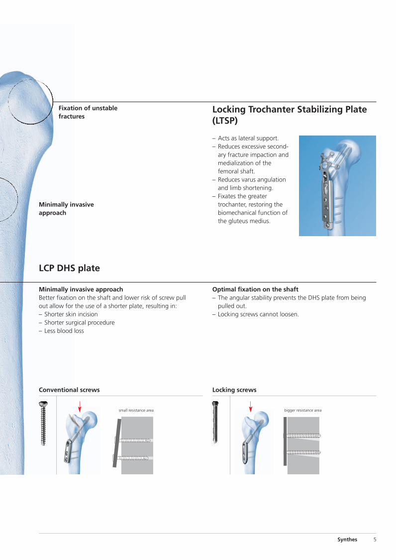
Locking Trochanter Stabilizing Plate(LTSP)
– Acts as lateral support.– Reduces excessive second-
ary fracture impaction andmedialization of thefemoral shaft.
– Reduces varus angulationand limb shortening.
– Fixates the greatertrochanter, restoring thebiomechanical function ofthe gluteus medius.
Fixation of unstablefractures
Conventional screws Locking screws
Optimal fixation on the shaft– The angular stability prevents the DHS plate from being
pulled out.– Locking screws cannot loosen.
small resistance area bigger resistance area
Minimally invasive approachBetter fixation on the shaft and lower risk of screw pullout allow for the use of a shorter plate, resulting in:– Shorter skin incision– Shorter surgical procedure– Less blood loss
Minimally invasiveapproach
0X6.000.255_AB.qxp:0X6.000.255_AB 04.12.2008 14:32 Uhr Seite 5
31-A1 31-A2 31-A3
31-B1 31-B2 31-B3
6 Synthes DHS/DCS System Technique Guide
Indications and Contraindications
DHS
Including all combinations of DHS Screw, DHS Blade, DHSplate with DCP holes and LCP DHS plate
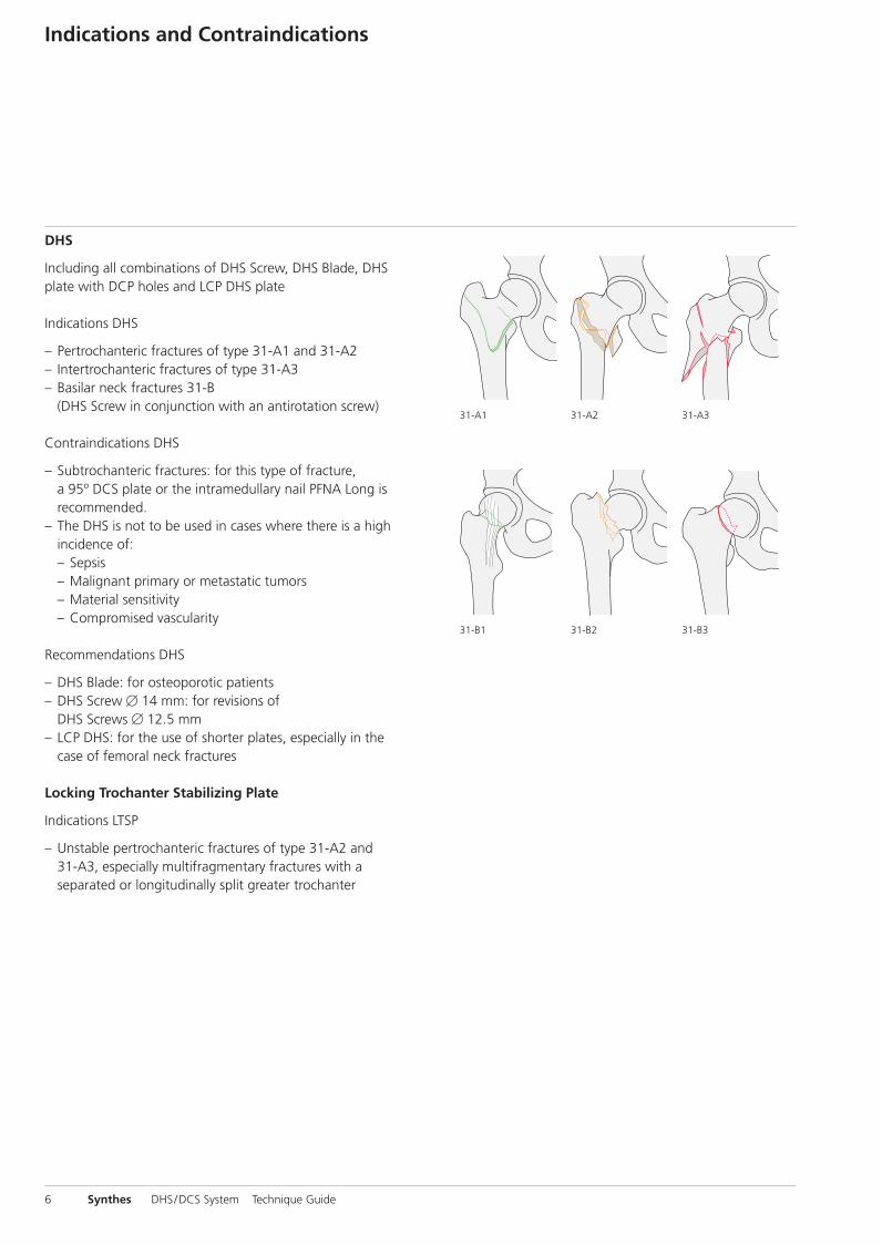
Indications DHS
– Pertrochanteric fractures of type 31-A1 and 31-A2– Intertrochanteric fractures of type 31-A3– Basilar neck fractures 31-B
(DHS Screw in conjunction with an antirotation screw)
Contraindications DHS
– Subtrochanteric fractures: for this type of fracture, a 95º DCS plate or the intramedullary nail PFNA Long isrecommended.
– The DHS is not to be used in cases where there is a highincidence of:– Sepsis– Malignant primary or metastatic tumors– Material sensitivity– Compromised vascularity
Recommendations DHS
– DHS Blade: for osteoporotic patients– DHS Screw � 14 mm: for revisions of
DHS Screws � 12.5 mm– LCP DHS: for the use of shorter plates, especially in the
case of femoral neck fractures
Locking Trochanter Stabilizing Plate
Indications LTSP
– Unstable pertrochanteric fractures of type 31-A2 and 31-A3, especially multifragmentary fractures with a separated or longitudinally split greater trochanter
0X6.000.255_AB.qxp:0X6.000.255_AB 04.12.2008 14:32 Uhr Seite 6
33-A2 33-A333-A1
33-C1 33-C2 33-C3
Synthes 7
DCS
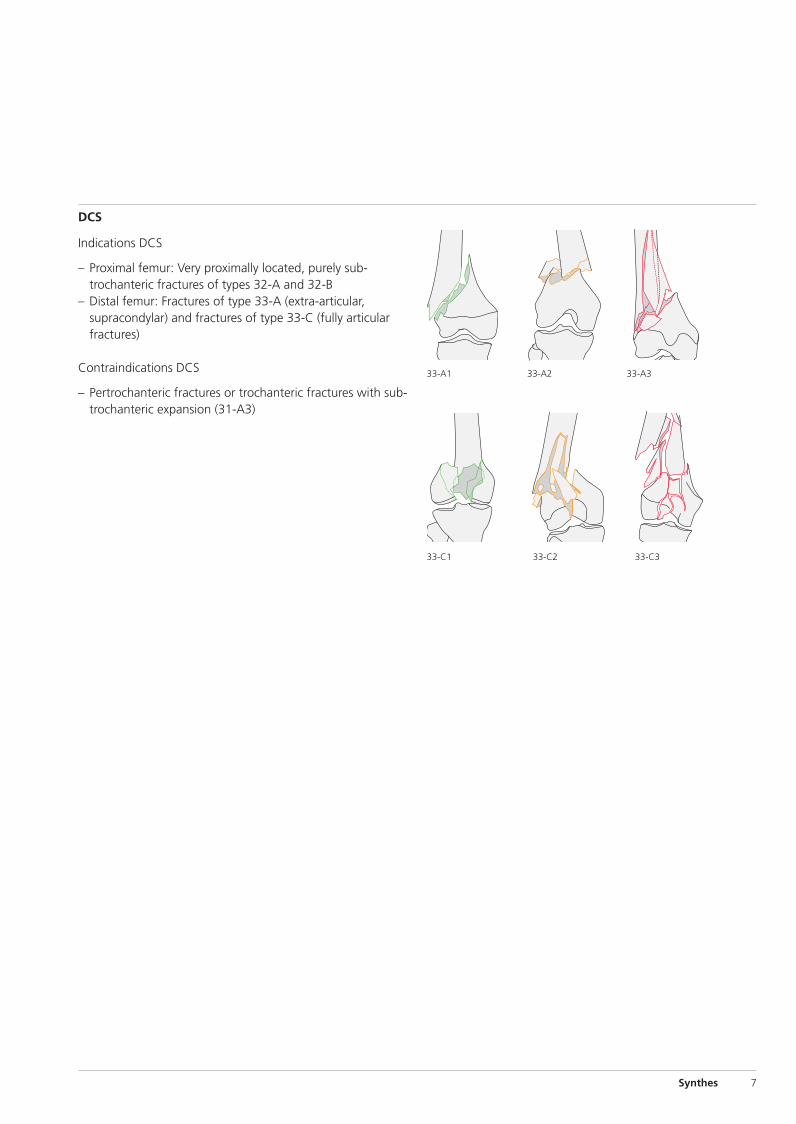
Indications DCS
– Proximal femur: Very proximally located, purely sub-trochanteric fractures of types 32-A and 32-B
– Distal femur: Fractures of type 33-A (extra-articular, supracondylar) and fractures of type 33-C (fully articularfractures)
Contraindications DCS
– Pertrochanteric fractures or trochanteric fractures with sub-trochanteric expansion (31-A3)
0X6.000.255_AB.qxp:0X6.000.255_AB 04.12.2008 14:32 Uhr Seite 7
8 Synthes DHS/DCS System Technique Guide
Clinical Cases
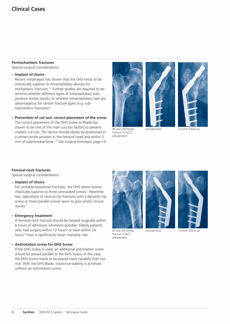
Pertrochanteric fracturesSpecial surgical considerations:
– Implant of choiceRecent metanalysis has shown that the DHS tends to bestatistically superior to intramedullary devices fortrochanteric fractures.3,4 Further studies are required to de-termine whether different types of intramedullary nailsproduce similar results, or whether intramedullary nails areadvantageous for certain fracture types (e.g. sub-trochanteric fractures).4
– Prevention of cut-out: correct placement of the screwThe correct placement of the DHS Screw or Blade hasshown to be one of the main success factors to preventimplant cut-out. The device should ideally be positioned ina center-center position in the femoral head and within 5mm of subchondral bone.5, 6 See surgical technique page 13.
Femoral neck fracturesSpecial surgical considerations:
– Implant of choiceFor unstable basicervial fractures, the DHS seems biome-chanically superior to three cannulated screws.7 Never the-less, operations of cervical hip fractures with a dynamic hipscrew or three parallel screws seem to give similar clinicalresults.8
– Emergency treatmentA femoral neck fracture should be treated surgically within6 hours of admission whenever possible. Elderly patientswho had surgery within 12 hours9 or even within 24hours10 have a significantly lower mortality rate.
– Antirotation screw for DHS ScrewIf the DHS Screw is used, an additional antirotation screwshould be placed parallel to the DHS Screw. In this case,the DHS Screw needs to be placed more caudally than nor-mal. With the DHS Blade, rotational stability is achievedwithout an antirotation screw.
81 year old female,fracture 31-B2.1,preoperative
postoperative 3 month follow-up
80 year old female,fracture 31-A2.2,preoperative
postoperative 3 month follow-up
0X6.000.255_AB.qxp:0X6.000.255_AB 04.12.2008 14:32 Uhr Seite 8

Synthes 9
0X6.000.255_AB.qxp:0X6.000.255_AB 04.12.2008 14:32 Uhr Seite 9
10 Synthes DHS/DCS System Technique Guide
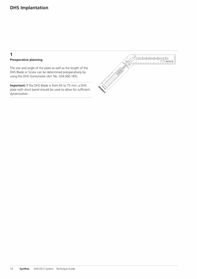
1Preoperative planning
The size and angle of the plate as well as the length of theDHS Blade or Screw can be determined preoperatively by using the DHS Goniometer (Art. No. 034.000.185).
Important: If the DHS Blade is from 65 to 75 mm, a DHSplate with short barrel should be used to allow for sufficientdynamization.
DHS Implantation
0X6.000.255_AB.qxp:0X6.000.255_AB 04.12.2008 14:32 Uhr Seite 10
Synthes 11
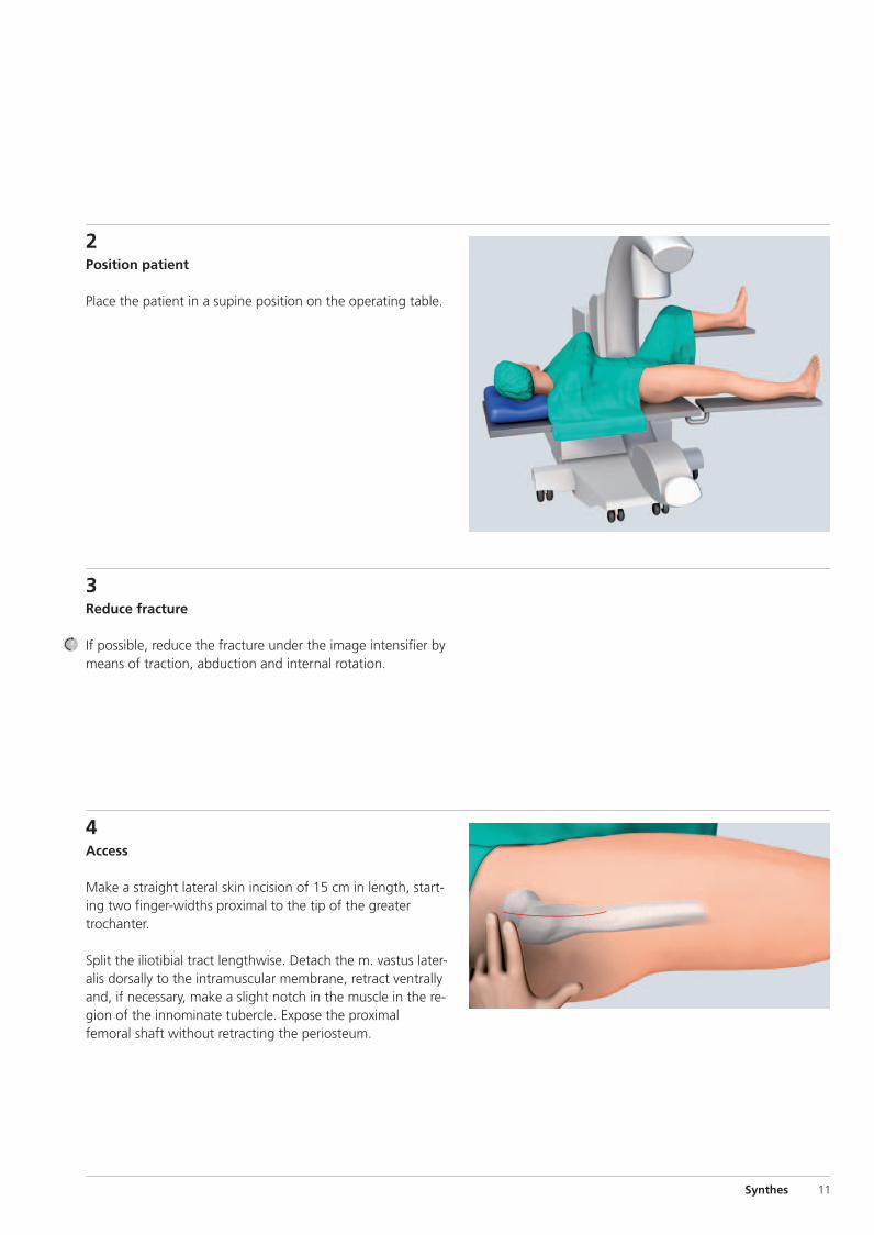
4Access
Make a straight lateral skin incision of 15 cm in length, start-ing two finger-widths proximal to the tip of the greatertrochanter.
Split the iliotibial tract lengthwise. Detach the m. vastus later-alis dorsally to the intramuscular membrane, retract ventrallyand, if necessary, make a slight notch in the muscle in the re-gion of the innominate tubercle. Expose the proximalfemoral shaft without retracting the periosteum.
2Position patient
Place the patient in a supine position on the operating table.
3Reduce fracture
If possible, reduce the fracture under the image intensifier bymeans of traction, abduction and internal rotation.
0X6.000.255_AB.qxp:0X6.000.255_AB 04.12.2008 14:32 Uhr Seite 11
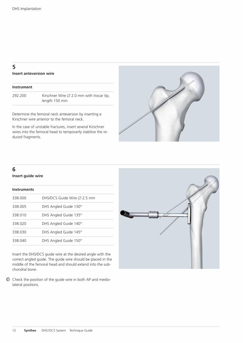
5Insert anteversion wire
Instrument
292.200 Kirschner Wire � 2.0 mm with trocar tip,length 150 mm
Determine the femoral neck anteversion by inserting aKirschner wire anterior to the femoral neck.
In the case of unstable fractures, insert several Kirschnerwires into the femoral head to temporarily stabilize the re-duced fragments.
6Insert guide wire
Instruments
338.000 DHS/DCS Guide Wire � 2.5 mm
338.005 DHS Angled Guide 130°
338.010 DHS Angled Guide 135°
338.020 DHS Angled Guide 140°
338.030 DHS Angled Guide 145°
338.040 DHS Angled Guide 150°
Insert the DHS/DCS guide wire at the desired angle with thecorrect angled guide. The guide wire should be placed in themiddle of the femoral head and should extend into the sub-chondral bone.
Check the position of the guide wire in both AP and medio-lateral positions.
12 Synthes DHS/DCS System Technique Guide
DHS Implantation
0X6.000.255_AB.qxp:0X6.000.255_AB 04.12.2008 14:32 Uhr Seite 12
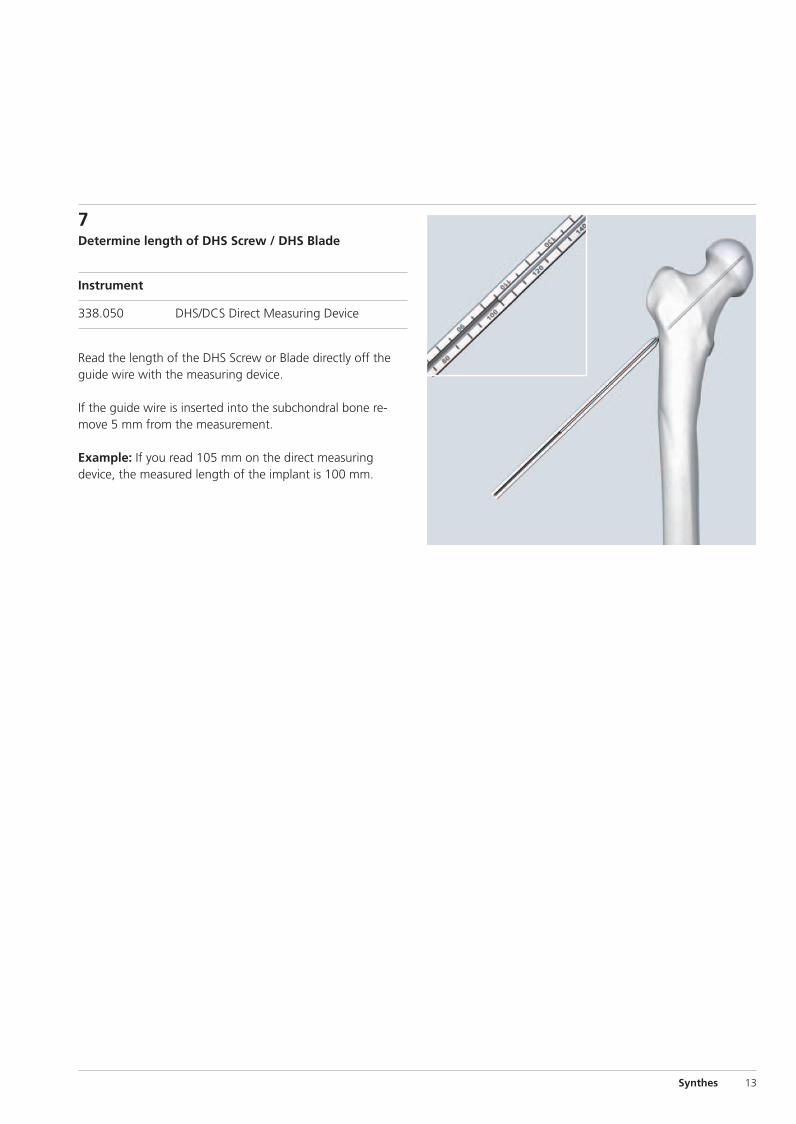
7Determine length of DHS Screw / DHS Blade
Instrument
338.050 DHS/DCS Direct Measuring Device
Read the length of the DHS Screw or Blade directly off theguide wire with the measuring device.
If the guide wire is inserted into the subchondral bone re-move 5 mm from the measurement.
Example: If you read 105 mm on the direct measuring device, the measured length of the implant is 100 mm.
Synthes 13
0X6.000.255_AB.qxp:0X6.000.255_AB 04.12.2008 14:32 Uhr Seite 13
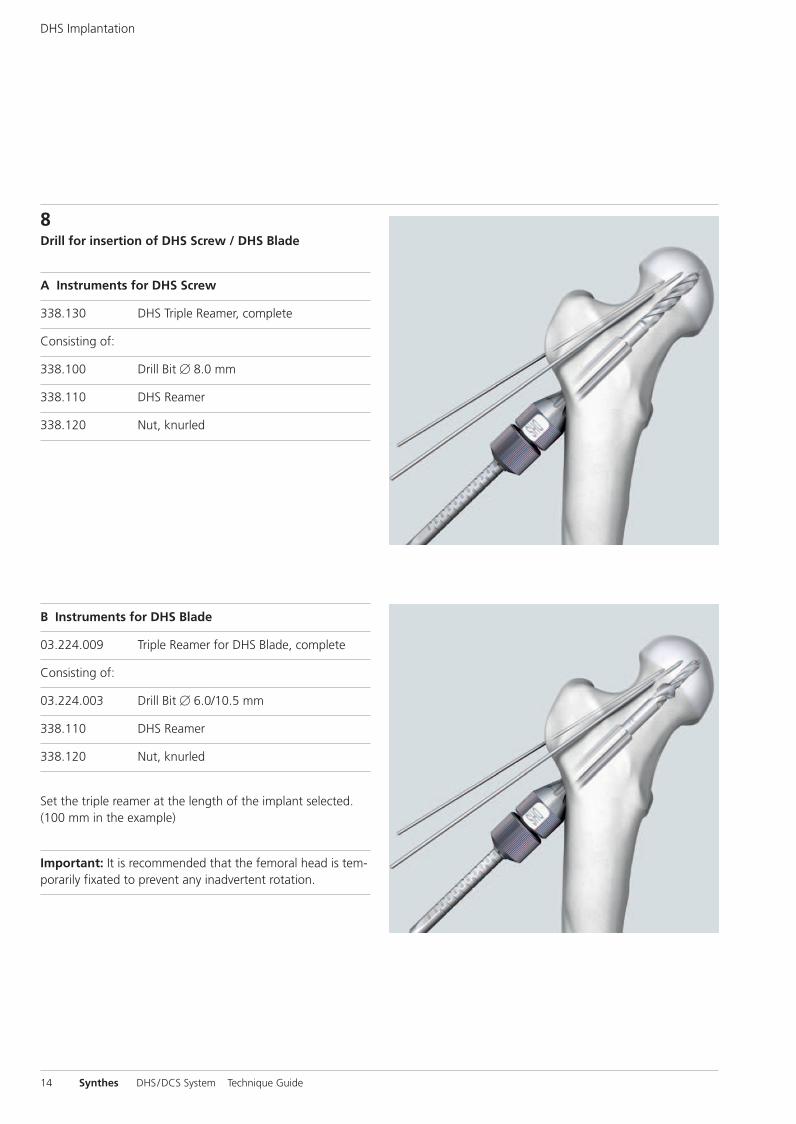
8Drill for insertion of DHS Screw / DHS Blade
A Instruments for DHS Screw
338.130 DHS Triple Reamer, complete
Consisting of:
338.100 Drill Bit � 8.0 mm
338.110 DHS Reamer
338.120 Nut, knurled
B Instruments for DHS Blade
03.224.009 Triple Reamer for DHS Blade, complete
Consisting of:
03.224.003 Drill Bit � 6.0/10.5 mm
338.110 DHS Reamer
338.120 Nut, knurled
Set the triple reamer at the length of the implant selected.(100 mm in the example)
Important: It is recommended that the femoral head is tem-porarily fixated to prevent any inadvertent rotation.
14 Synthes DHS/DCS System Technique Guide
DHS Implantation
0X6.000.255_AB.qxp:0X6.000.255_AB 04.12.2008 14:32 Uhr Seite 14
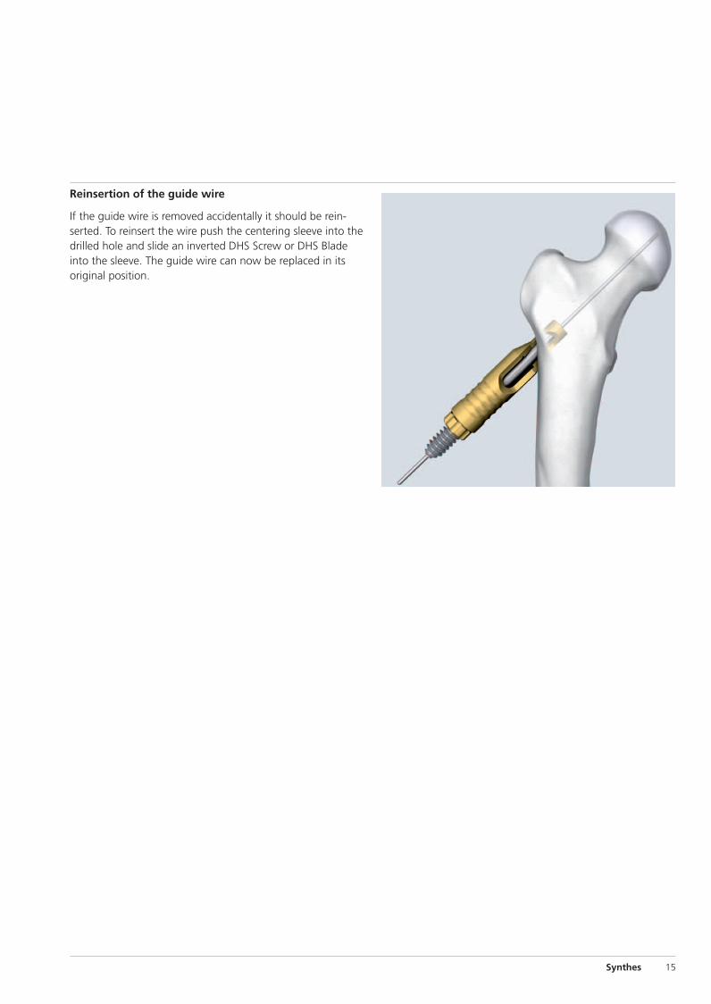
Reinsertion of the guide wire
If the guide wire is removed accidentally it should be re in-serted. To reinsert the wire push the centering sleeve into thedrilled hole and slide an inverted DHS Screw or DHS Bladeinto the sleeve. The guide wire can now be replaced in itsoriginal position.
Synthes 15
0X6.000.255_AB.qxp:0X6.000.255_AB 04.12.2008 14:32 Uhr Seite 15
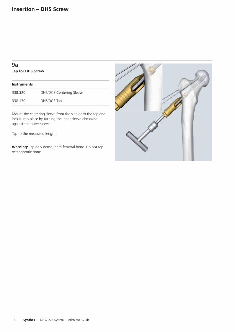
9aTap for DHS Screw
Instruments
338.320 DHS/DCS Centering Sleeve
338.170 DHS/DCS Tap
Mount the centering sleeve from the side onto the tap andlock it into place by turning the inner sleeve clockwiseagainst the outer sleeve.
Tap to the measured length.
Warning: Tap only dense, hard femoral bone. Do not tap osteoporotic bone.
16 Synthes DHS/DCS System Technique Guide
Insertion – DHS Screw
0X6.000.255_AB.qxp:0X6.000.255_AB 04.12.2008 14:32 Uhr Seite 16
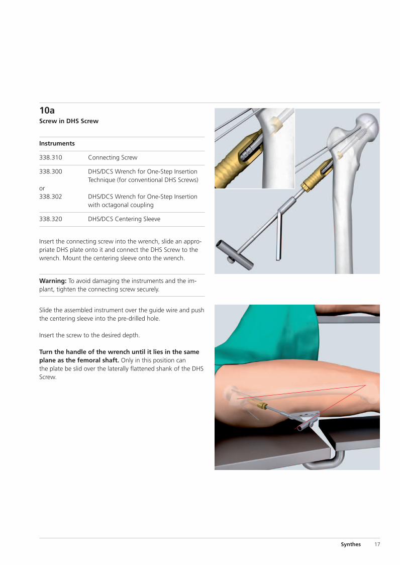
10aScrew in DHS Screw
Instruments
338.310 Connecting Screw
338.300 DHS/DCS Wrench for One-Step InsertionTechnique (for conventional DHS Screws)
or338.302 DHS/DCS Wrench for One-Step Insertion
with octagonal coupling
338.320 DHS/DCS Centering Sleeve
Insert the connecting screw into the wrench, slide an appro-priate DHS plate onto it and connect the DHS Screw to thewrench. Mount the centering sleeve onto the wrench.
Warning: To avoid damaging the instruments and the im-plant, tighten the connecting screw securely.
Slide the assembled instrument over the guide wire and pushthe centering sleeve into the pre-drilled hole.
Insert the screw to the desired depth.
Turn the handle of the wrench until it lies in the sameplane as the femoral shaft. Only in this position canthe plate be slid over the laterally flattened shank of the DHSScrew.
Synthes 17
0X6.000.255_AB.qxp:0X6.000.255_AB 04.12.2008 14:32 Uhr Seite 17
18 Synthes DHS/DCS System Technique Guide
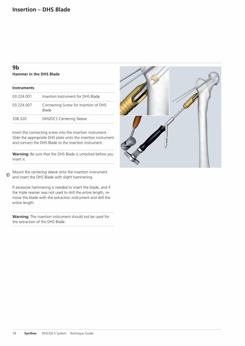
9bHammer in the DHS Blade
Instruments
03.224.001 Insertion Instrument for DHS Blade
03.224.007 Connecting Screw for Insertion of DHSBlade
338.320 DHS/DCS Centering Sleeve
Insert the connecting screw into the insertion instrument.Slide the appropriate DHS plate onto the insertion instrumentand connect the DHS Blade to the insertion instrument.
Warning: Be sure that the DHS Blade is unlocked before youinsert it.
Mount the centering sleeve onto the insertion instrumentand insert the DHS Blade with slight hammering.
If excessive hammering is needed to insert the blade, and ifthe triple reamer was not used to drill the entire length, re-move the blade with the extraction instrument and drill theentire length.
Warning: The insertion instrument should not be used forthe extraction of the DHS Blade.
Insertion – DHS Blade
0X6.000.255_AB.qxp:0X6.000.255_AB 04.12.2008 14:32 Uhr Seite 18
Synthes 19
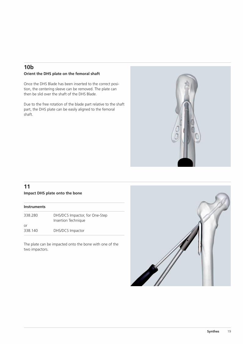
10bOrient the DHS plate on the femoral shaft
Once the DHS Blade has been inserted to the correct posi-tion, the centering sleeve can be removed. The plate canthen be slid over the shaft of the DHS Blade.
Due to the free rotation of the blade part relative to the shaftpart, the DHS plate can be easily aligned to the femoralshaft.
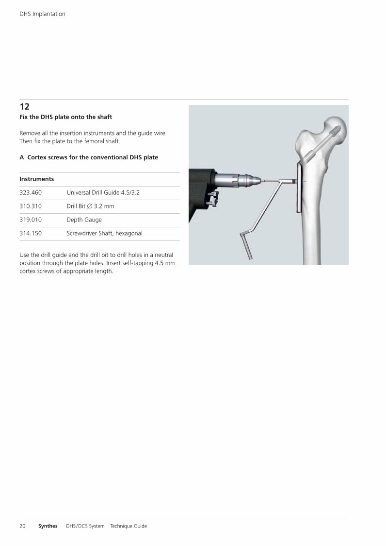
11Impact DHS plate onto the bone
Instruments
338.280 DHS/DCS Impactor, for One-StepInsertion Technique
or338.140 DHS/DCS Impactor
The plate can be impacted onto the bone with one of thetwo impactors.
0X6.000.255_AB.qxp:0X6.000.255_AB 04.12.2008 14:32 Uhr Seite 19
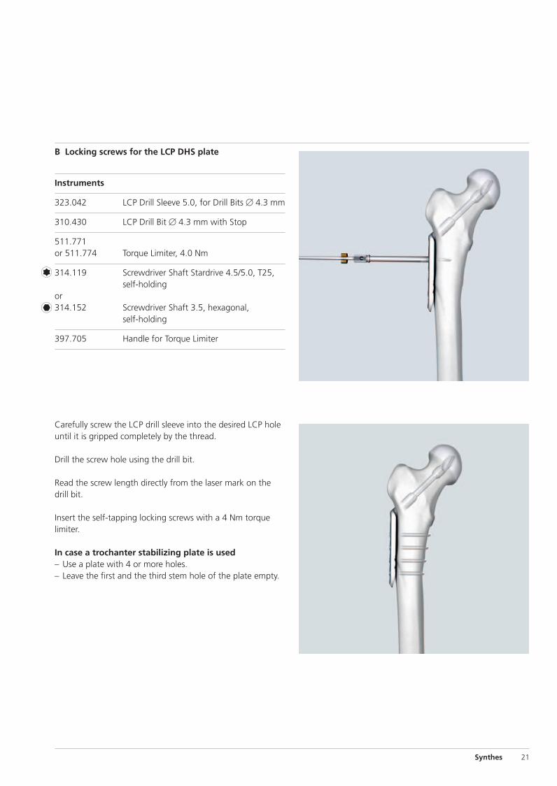
12Fix the DHS plate onto the shaft
Remove all the insertion instruments and the guide wire.Then fix the plate to the femoral shaft.
A Cortex screws for the conventional DHS plate
Instruments
323.460 Universal Drill Guide 4.5/3.2
310.310 Drill Bit � 3.2 mm
319.010 Depth Gauge
314.150 Screwdriver Shaft, hexagonal
Use the drill guide and the drill bit to drill holes in a neutralposition through the plate holes. Insert self-tapping 4.5 mmcortex screws of appropriate length.
20 Synthes DHS/DCS System Technique Guide
DHS Implantation
0X6.000.255_AB.qxp:0X6.000.255_AB 04.12.2008 14:32 Uhr Seite 20
Carefully screw the LCP drill sleeve into the desired LCP holeuntil it is gripped completely by the thread.
Drill the screw hole using the drill bit.
Read the screw length directly from the laser mark on thedrill bit.
Insert the self-tapping locking screws with a 4 Nm torquelimiter.
In case a trochanter stabilizing plate is used– Use a plate with 4 or more holes.– Leave the first and the third stem hole of the plate empty.
B Locking screws for the LCP DHS plate
Instruments
323.042 LCP Drill Sleeve 5.0, for Drill Bits � 4.3 mm
310.430 LCP Drill Bit � 4.3 mm with Stop
511.771or 511.774 Torque Limiter, 4.0 Nm
314.119 Screwdriver Shaft Stardrive 4.5/5.0, T25,self-holding
or314.152 Screwdriver Shaft 3.5, hexagonal,
self-holding
397.705 Handle for Torque Limiter
Synthes 21
0X6.000.255_AB.qxp:0X6.000.255_AB 04.12.2008 14:32 Uhr Seite 21
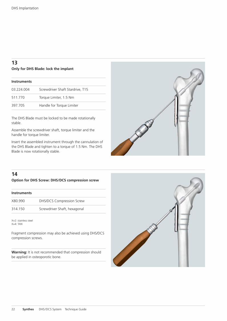
13Only for DHS Blade: lock the implant
Instruments
03.224.004 Screwdriver Shaft Stardrive, T15
511.770 Torque Limiter, 1.5 Nm
397.705 Handle for Torque Limiter
The DHS Blade must be locked to be made rotationally stable.
Assemble the screwdriver shaft, torque limiter and the handle for torque limiter.
Insert the assembled instrument through the cannulation ofthe DHS Blade and tighten to a torque of 1.5 Nm. The DHSBlade is now rotationally stable.
14Option for DHS Screw: DHS/DCS compression screw
Instruments
X80.990 DHS/DCS Compression Screw
314.150 Screwdriver Shaft, hexagonal
X=2: stainless steelX=4: TAN
Fragment compression may also be achieved using DHS/DCScompression screws.
Warning: It is not recommended that compression shouldbe applied in osteoporotic bone.
22 Synthes DHS/DCS System Technique Guide
DHS Implantation
0X6.000.255_AB.qxp:0X6.000.255_AB 04.12.2008 14:32 Uhr Seite 22
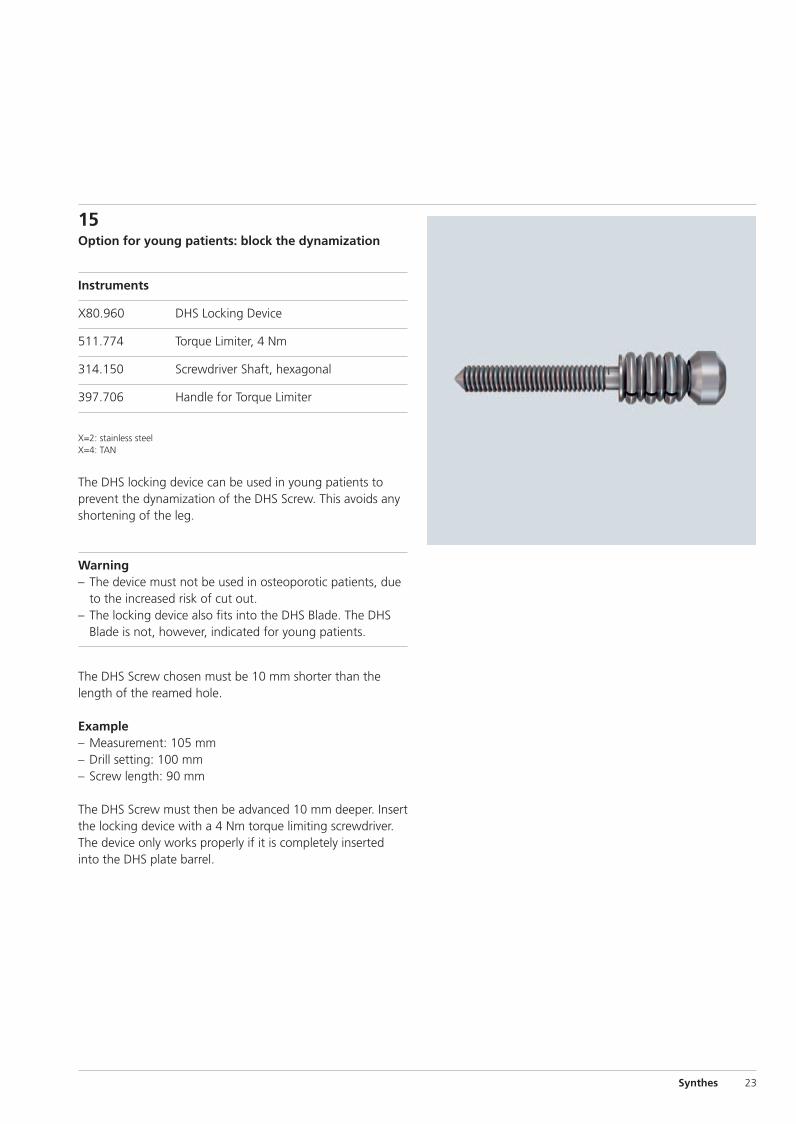
15Option for young patients: block the dynamization
Instruments
X80.960 DHS Locking Device
511.774 Torque Limiter, 4 Nm
314.150 Screwdriver Shaft, hexagonal
397.706 Handle for Torque Limiter
X=2: stainless steelX=4: TAN
The DHS locking device can be used in young patients toprevent the dynamization of the DHS Screw. This avoids anyshortening of the leg.
Warning– The device must not be used in osteoporotic patients, due
to the increased risk of cut out.– The locking device also fits into the DHS Blade. The DHS
Blade is not, however, indicated for young patients.
The DHS Screw chosen must be 10 mm shorter than thelength of the reamed hole.
Example– Measurement: 105 mm– Drill setting: 100 mm– Screw length: 90 mm
The DHS Screw must then be advanced 10 mm deeper. Insertthe locking device with a 4 Nm torque limiting screwdriver.The device only works properly if it is completely insertedinto the DHS plate barrel.
Synthes 23
0X6.000.255_AB.qxp:0X6.000.255_AB 04.12.2008 14:32 Uhr Seite 23
24 Synthes DHS/DCS System Technique Guide
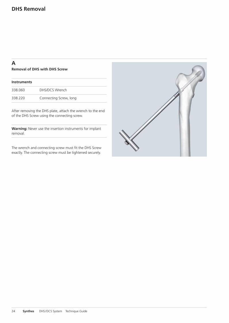
ARemoval of DHS with DHS Screw
Instruments
338.060 DHS/DCS Wrench
338.220 Connecting Screw, long
After removing the DHS plate, attach the wrench to the endof the DHS Screw using the connecting screw.
Warning: Never use the insertion instruments for implant removal.
The wrench and connecting screw must fit the DHS Screwexactly. The connecting screw must be tightened securely.
DHS Removal
0X6.000.255_AB.qxp:0X6.000.255_AB 04.12.2008 14:32 Uhr Seite 24
Synthes 25
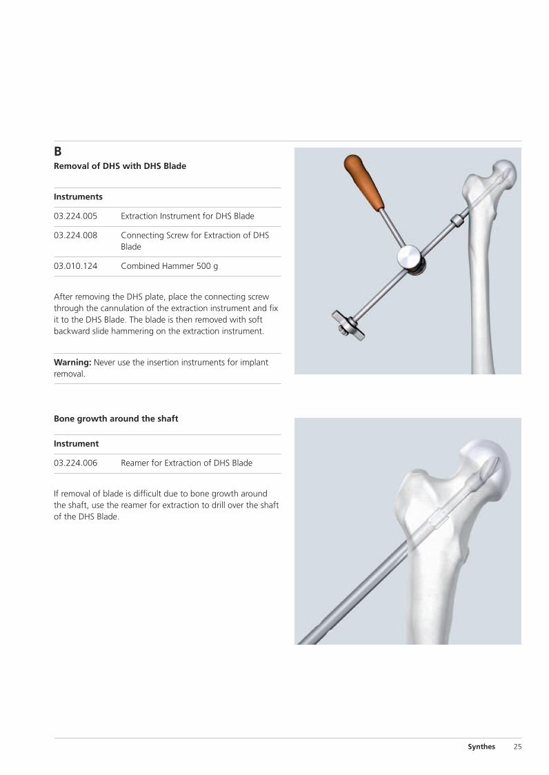
BRemoval of DHS with DHS Blade
Instruments
03.224.005 Extraction Instrument for DHS Blade
03.224.008 Connecting Screw for Extraction of DHSBlade
03.010.124 Combined Hammer 500 g
After removing the DHS plate, place the connecting screwthrough the cannulation of the extraction instrument and fixit to the DHS Blade. The blade is then removed with softbackward slide hammering on the extraction instrument.
Warning: Never use the insertion instruments for implant removal.
Bone growth around the shaft
Instrument
03.224.006 Reamer for Extraction of DHS Blade
If removal of blade is difficult due to bone growth aroundthe shaft, use the reamer for extraction to drill over the shaftof the DHS Blade.
0X6.000.255_AB.qxp:0X6.000.255_AB 04.12.2008 14:32 Uhr Seite 25
26 Synthes DHS/DCS System Technique Guide
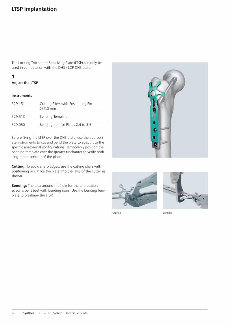
The Locking Trochanter Stabilizing Plate (LTSP) can only beused in combination with the DHS / LCP DHS plate.
1Adjust the LTSP
Instruments
329.151 Cutting Pliers with Positioning Pin� 3.0 mm
329.513 Bending Template
329.050 Bending Iron for Plates 2.4 to 3.5
Before fixing the LTSP over the DHS plate, use the appropri-ate instruments to cut and bend the plate to adapt it to thespecific anatomical configurations. Temporarily position thebending template over the greater trochanter to verify bothlength and contour of the plate.
Cutting: To avoid sharp edges, use the cutting pliers withpositioning pin. Place the plate into the jaws of the cutter asshown.
Bending: The area around the hole for the antirotationscrew is bent best with bending irons. Use the bending tem-plate to preshape the LTSP.
LTSP Implantation
Cutting Bending
0X6.000.255_AB.qxp:0X6.000.255_AB 04.12.2008 14:32 Uhr Seite 26
Synthes 27
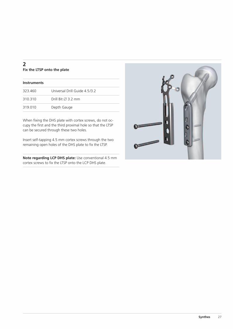
2Fix the LTSP onto the plate
Instruments
323.460 Universal Drill Guide 4.5/3.2
310.310 Drill Bit � 3.2 mm
319.010 Depth Gauge
When fixing the DHS plate with cortex screws, do not oc-cupy the first and the third proximal hole so that the LTSPcan be secured through these two holes.
Insert self-tapping 4.5 mm cortex screws through the two remaining open holes of the DHS plate to fix the LTSP.
Note regarding LCP DHS plate: Use conventional 4.5 mmcortex screws to fix the LTSP onto the LCP DHS plate.
0X6.000.255_AB.qxp:0X6.000.255_AB 04.12.2008 14:32 Uhr Seite 27
28 Synthes DHS/DCS System Technique Guide
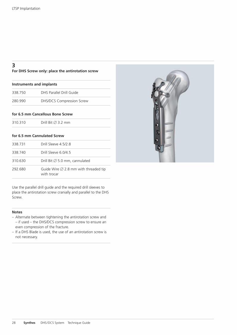
3For DHS Screw only: place the antirotation screw
Instruments and implants
338.750 DHS Parallel Drill Guide
280.990 DHS/DCS Compression Screw
for 6.5 mm Cancellous Bone Screw
310.310 Drill Bit � 3.2 mm
for 6.5 mm Cannulated Screw
338.731 Drill Sleeve 4.5/2.8
338.740 Drill Sleeve 6.0/4.5
310.630 Drill Bit � 5.0 mm, cannulated
292.680 Guide Wire � 2.8 mm with threaded tipwith trocar
Use the parallel drill guide and the required drill sleeves toplace the antirotation screw cranially and parallel to the DHSScrew.
Notes– Alternate between tightening the antirotation screw and
– if used – the DHS/DCS compression screw to ensure aneven compression of the fracture.
– If a DHS Blade is used, the use of an antirotation screw isnot necessary.
LTSP Implantation
0X6.000.255_AB.qxp:0X6.000.255_AB 04.12.2008 14:32 Uhr Seite 28
Synthes 29
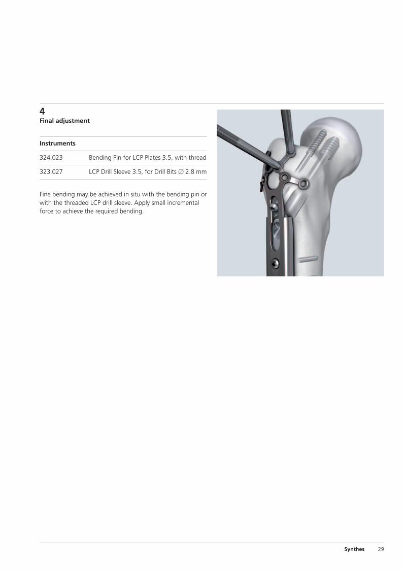
4Final adjustment
Instruments
324.023 Bending Pin for LCP Plates 3.5, with thread
323.027 LCP Drill Sleeve 3.5, for Drill Bits � 2.8 mm
Fine bending may be achieved in situ with the bending pin orwith the threaded LCP drill sleeve. Apply small incrementalforce to achieve the required bending.
0X6.000.255_AB.qxp:0X6.000.255_AB 04.12.2008 14:32 Uhr Seite 29
30 Synthes DHS/DCS System Technique Guide
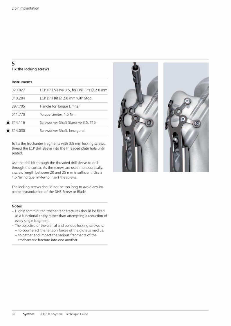
5Fix the locking screws
Instruments
323.027 LCP Drill Sleeve 3.5, for Drill Bits � 2.8 mm
310.284 LCP Drill Bit � 2.8 mm with Stop
397.705 Handle for Torque Limiter
511.770 Torque Limiter, 1.5 Nm
314.116 Screwdriver Shaft Stardrive 3.5, T15
314.030 Screwdriver Shaft, hexagonal
To fix the trochanter fragments with 3.5 mm locking screws,thread the LCP drill sleeve into the threaded plate hole untilseated.
Use the drill bit through the threaded drill sleeve to drillthrough the cortex. As the screws are used monocortically,a screw length between 20 and 25 mm is sufficient. Use a1.5 Nm torque limiter to insert the screws.
The locking screws should not be too long to avoid any im-paired dynamization of the DHS Screw or Blade.
Notes– Highly comminuted trochanteric fractures should be fixed
as a functional entity rather than attempting a reduction ofevery single fragment.
– The objective of the cranial and oblique locking screws is:– to counteract the tension forces of the gluteus medius. – to gather and impact the various fragments of the
trochanteric fracture into one another.
LTSP Implantation
0X6.000.255_AB.qxp:0X6.000.255_AB 04.12.2008 14:32 Uhr Seite 30

Synthes 31
LTSP Removal
Remove the implants in the following sequence:– All fixation elements (screws, wire, cable, suture) attached
to the LTSP – Antirotation screw (if used)– Trochanter Stabilizing Plate– Compression screw– LCP DHS plate – DHS Screw or DHS Blade
0X6.000.255_AB.qxp:0X6.000.255_AB 04.12.2008 14:32 Uhr Seite 31
1/3 2/3 3/3
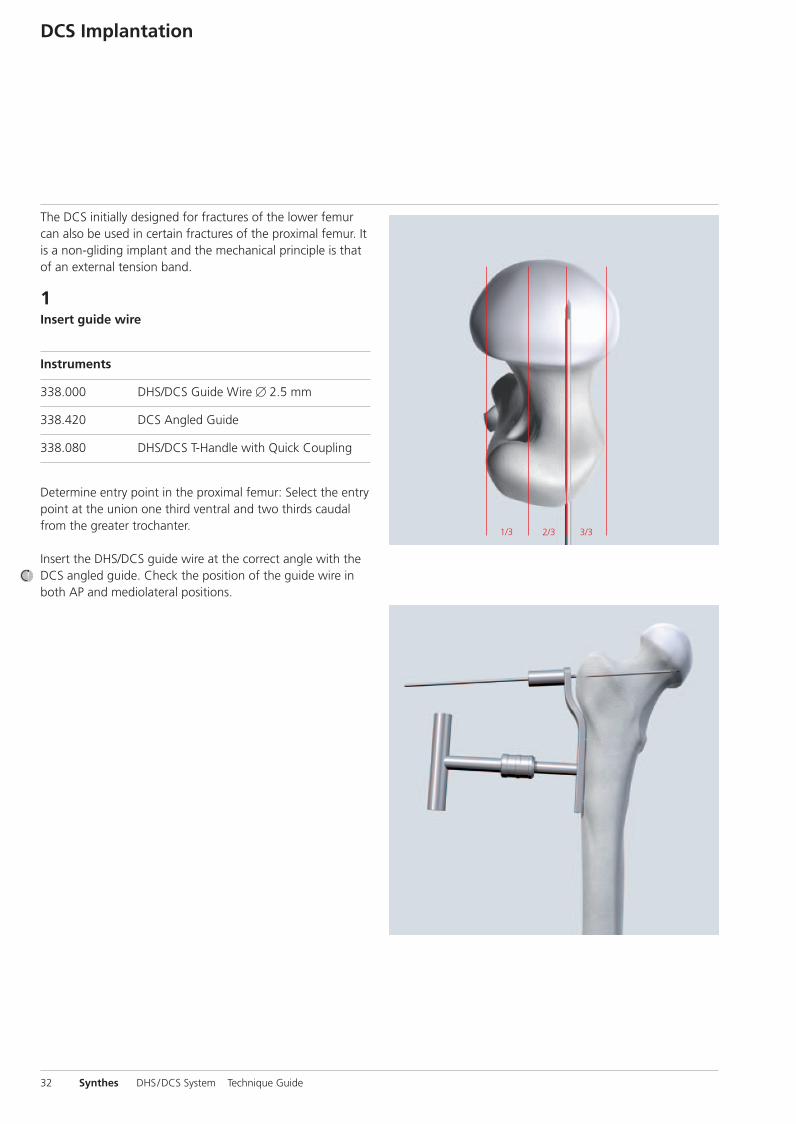
The DCS initially designed for fractures of the lower femurcan also be used in certain fractures of the proximal femur. Itis a non-gliding implant and the mechanical principle is thatof an external tension band.
1Insert guide wire
Instruments
338.000 DHS/DCS Guide Wire � 2.5 mm
338.420 DCS Angled Guide
338.080 DHS/DCS T-Handle with Quick Coupling
Determine entry point in the proximal femur: Select the entrypoint at the union one third ventral and two thirds caudalfrom the greater trochanter.
Insert the DHS/DCS guide wire at the correct angle with theDCS angled guide. Check the position of the guide wire inboth AP and mediolateral positions.
32 Synthes DHS/DCS System Technique Guide
DCS Implantation
0X6.000.255_AB.qxp:0X6.000.255_AB 04.12.2008 14:32 Uhr Seite 32
Synthes 33
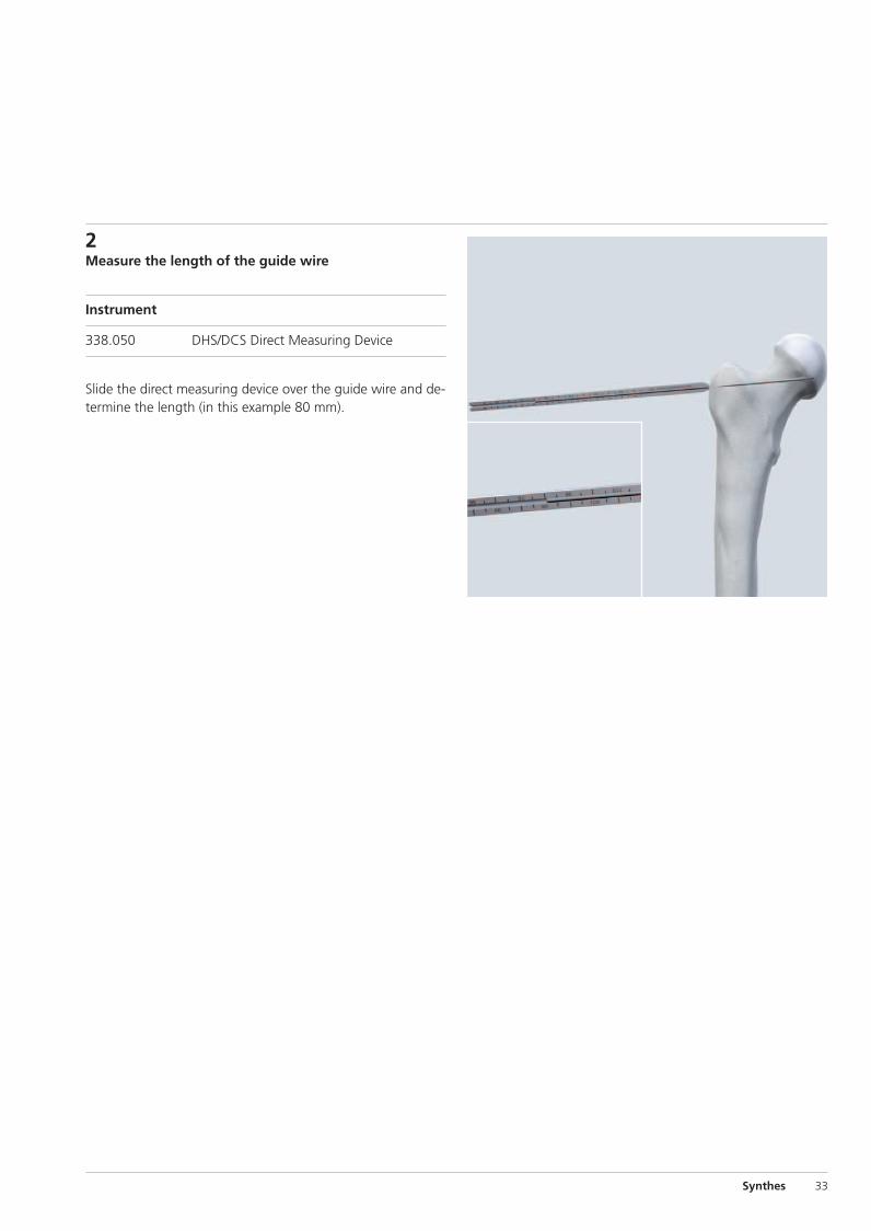
2Measure the length of the guide wire
Instrument
338.050 DHS/DCS Direct Measuring Device
Slide the direct measuring device over the guide wire and de-termine the length (in this example 80 mm).
0X6.000.255_AB.qxp:0X6.000.255_AB 04.12.2008 14:32 Uhr Seite 33
34 Synthes DHS/DCS System Technique Guide
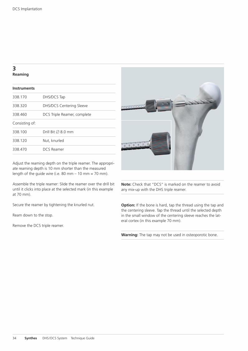
3Reaming
Instruments
338.170 DHS/DCS Tap
338.320 DHS/DCS Centering Sleeve
338.460 DCS Triple Reamer, complete
Consisting of:
338.100 Drill Bit � 8.0 mm
338.120 Nut, knurled
338.470 DCS Reamer
Adjust the reaming depth on the triple reamer. The appropri-ate reaming depth is 10 mm shorter than the measuredlength of the guide wire (i.e. 80 mm – 10 mm = 70 mm).
Assemble the triple reamer: Slide the reamer over the drill bituntil it clicks into place at the selected mark (in this exampleat 70 mm).
Secure the reamer by tightening the knurled nut.
Ream down to the stop.
Remove the DCS triple reamer.
Note: Check that “DCS“ is marked on the reamer to avoidany mix-up with the DHS triple reamer.
Option: If the bone is hard, tap the thread using the tap andthe centering sleeve. Tap the thread until the selected depthin the small window of the centering sleeve reaches the lat-eral cortex (in this example 70 mm).
Warning: The tap may not be used in osteoporotic bone.
DCS Implantation
0X6.000.255_AB.qxp:0X6.000.255_AB 04.12.2008 14:32 Uhr Seite 34
Synthes 35
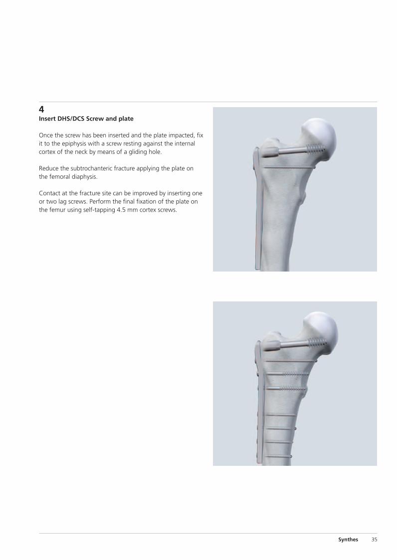
4Insert DHS/DCS Screw and plate
Once the screw has been inserted and the plate impacted, fixit to the epiphysis with a screw resting against the internalcortex of the neck by means of a gliding hole.
Reduce the subtrochanteric fracture applying the plate onthe femoral diaphysis.
Contact at the fracture site can be improved by inserting oneor two lag screws. Perform the final fixation of the plate onthe femur using self-tapping 4.5 mm cortex screws.
0X6.000.255_AB.qxp:0X6.000.255_AB 04.12.2008 14:32 Uhr Seite 35

Remove the implants in the following sequence:– DCS plate– DHS/DCS Screw
Please also refer to DHS implant removal, page 24.
DCS Removal
36 Synthes DHS/DCS System Technique Guide
0X6.000.255_AB.qxp:0X6.000.255_AB 04.12.2008 14:32 Uhr Seite 36
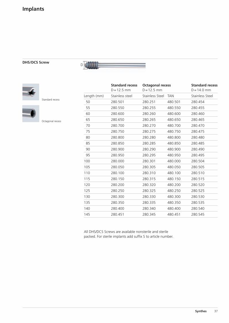
D
All DHS/DCS Screws are available nonsterile and sterilepacked. For sterile implants add suffix S to article number.
Standard recess Octagonal recess Standard recessD=12.5 mm D=12.5 mm D=14.0 mm
Length (mm) Stainless steel Stainless Steel TAN Stainless Steel
50 280.501 280.251 480.501 280.454
55 280.550 280.255 480.550 280.455
60 280.600 280.260 480.600 280.460
65 280.650 280.265 480.650 280.465
70 280.700 280.270 480.700 280.470
75 280.750 280.275 480.750 280.475
80 280.800 280.280 480.800 280.480
85 280.850 280.285 480.850 280.485
90 280.900 280.290 480.900 280.490
95 280.950 280.295 480.950 280.495
100 280.000 280.301 480.000 280.504
105 280.050 280.305 480.050 280.505
110 280.100 280.310 480.100 280.510
115 280.150 280.315 480.150 280.515
120 280.200 280.320 480.200 280.520
125 280.250 280.325 480.250 280.525
130 280.300 280.330 480.300 280.530
135 280.350 280.335 480.350 280.535
140 280.400 280.340 480.400 280.540
145 280.451 280.345 480.451 280.545
DHS/DCS Screw
Implants
Synthes 37
Standard recess
Octagonal recess
0X6.000.255_AB.qxp:0X6.000.255_AB 04.12.2008 14:32 Uhr Seite 37
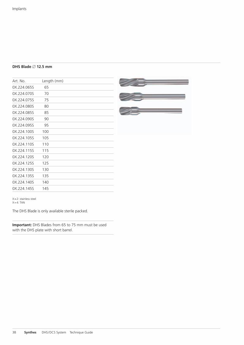
Art. No. Length (mm)
0X.224.065S 65
0X.224.070S 70
0X.224.075S 75
0X.224.080S 80
0X.224.085S 85
0X.224.090S 90
0X.224.095S 95
0X.224.100S 100
0X.224.105S 105
0X.224.110S 110
0X.224.115S 115
0X.224.120S 120
0X.224.125S 125
0X.224.130S 130
0X.224.135S 135
0X.224.140S 140
0X.224.145S 145
X=2: stainless steelX=4: TAN
The DHS Blade is only available sterile packed.
Important: DHS Blades from 65 to 75 mm must be usedwith the DHS plate with short barrel.
DHS Blade � 12.5 mm
Implants
38 Synthes DHS/DCS System Technique Guide
0X6.000.255_AB.qxp:0X6.000.255_AB 04.12.2008 14:32 Uhr Seite 38
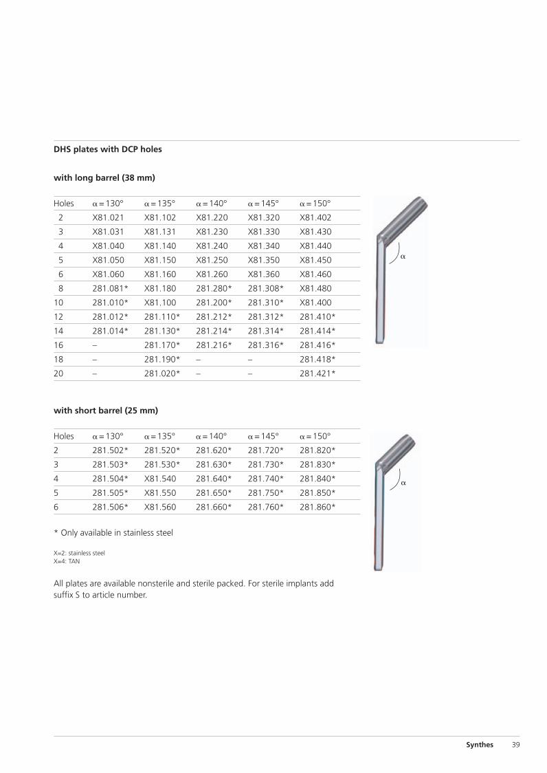
�
�
with long barrel (38 mm)
Holes �=130° �=135° �=140° �=145° �=150°
2 X81.021 X81.102 X81.220 X81.320 X81.402
3 X81.031 X81.131 X81.230 X81.330 X81.430
4 X81.040 X81.140 X81.240 X81.340 X81.440
5 X81.050 X81.150 X81.250 X81.350 X81.450
6 X81.060 X81.160 X81.260 X81.360 X81.460
8 281.081* X81.180 281.280* 281.308* X81.480
10 281.010* X81.100 281.200* 281.310* X81.400
12 281.012* 281.110* 281.212* 281.312* 281.410*
14 281.014* 281.130* 281.214* 281.314* 281.414*
16 – 281.170* 281.216* 281.316* 281.416*
18 – 281.190* – – 281.418*
20 – 281.020* – – 281.421*
with short barrel (25 mm)
Holes �=130° �=135° �=140° �=145° �=150°
2 281.502* 281.520* 281.620* 281.720* 281.820*
3 281.503* 281.530* 281.630* 281.730* 281.830*
4 281.504* X81.540 281.640* 281.740* 281.840*
5 281.505* X81.550 281.650* 281.750* 281.850*
6 281.506* X81.560 281.660* 281.760* 281.860*
* Only available in stainless steel
X=2: stainless steelX=4: TAN
All plates are available nonsterile and sterile packed. For sterile implants addsuffix S to article number.
DHS plates with DCP holes
Synthes 39
0X6.000.255_AB.qxp:0X6.000.255_AB 04.12.2008 14:32 Uhr Seite 39
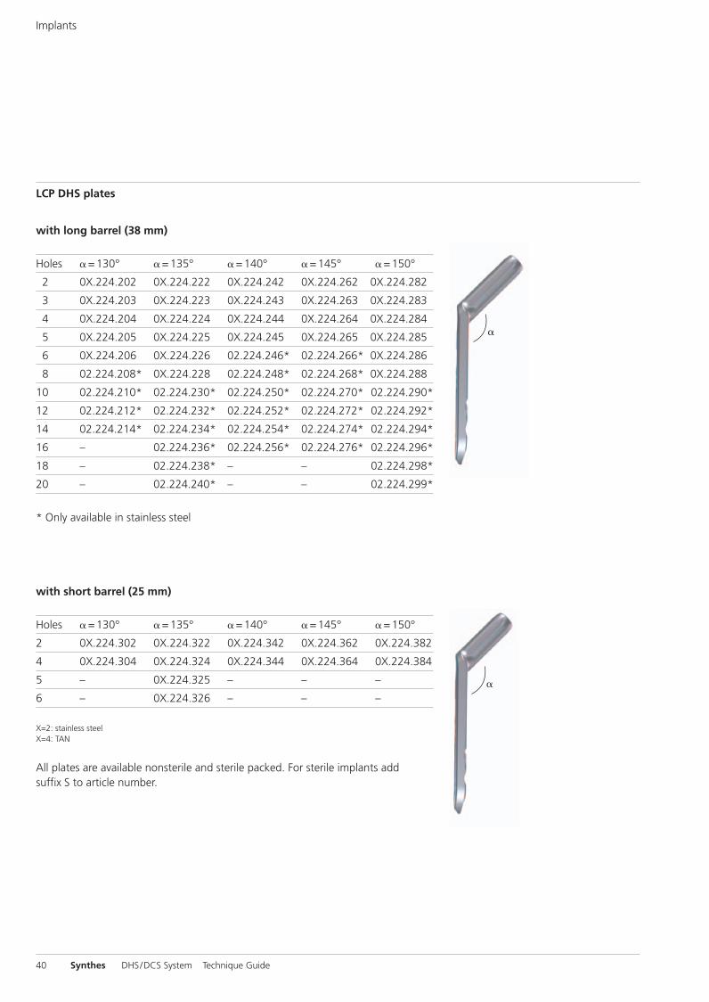
�
�
with long barrel (38 mm)
Holes �=130° �=135° �=140° �=145° �=150°
2 0X.224.202 0X.224.222 0X.224.242 0X.224.262 0X.224.282*
3 0X.224.203 0X.224.223 0X.224.243 0X.224.263 0X.224.283*
4 0X.224.204 0X.224.224 0X.224.244 0X.224.264 0X.224.284*
5 0X.224.205 0X.224.225 0X.224.245 0X.224.265 0X.224.285*
6 0X.224.206 0X.224.226 02.224.246* 02.224.266* 0X.224.286*
8 02.224.208* 0X.224.228 02.224.248* 02.224.268* 0X.224.288*
10 02.224.210* 02.224.230* 02.224.250* 02.224.270* 02.224.290*
12 02.224.212* 02.224.232* 02.224.252* 02.224.272* 02.224.292*
14 02.224.214* 02.224.234* 02.224.254* 02.224.274* 02.224.294*
16 – 02.224.236* 02.224.256* 02.224.276* 02.224.296*
18 – 02.224.238* – – 02.224.298*
20 – 02.224.240* – – 02.224.299*
* Only available in stainless steel
with short barrel (25 mm)
Holes �=130° �=135° �=140° �=145° �=150°
2 0X.224.302 0X.224.322 0X.224.342 0X.224.362 0X.224.382
4 0X.224.304 0X.224.324 0X.224.344 0X.224.364 0X.224.384
5 – 0X.224.325 – – –
6 – 0X.224.326 – – –
X=2: stainless steelX=4: TAN
All plates are available nonsterile and sterile packed. For sterile implants addsuffix S to article number.
LCP DHS plates
Implants
40 Synthes DHS/DCS System Technique Guide
0X6.000.255_AB.qxp:0X6.000.255_AB 04.12.2008 14:32 Uhr Seite 40
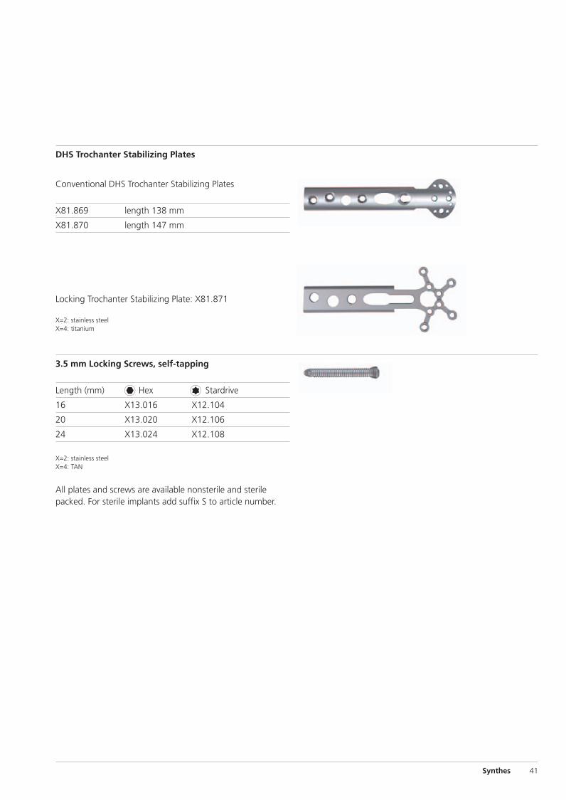
Conventional DHS Trochanter Stabilizing Plates
X81.869 length 138 mm
X81.870 length 147 mm
Locking Trochanter Stabilizing Plate: X81.871
X=2: stainless steelX=4: titanium
DHS Trochanter Stabilizing Plates
3.5 mm Locking Screws, self-tapping
Length (mm) Hex Stardrive
16 X13.016 X12.104
20 X13.020 X12.106
24 X13.024 X12.108
X=2: stainless steelX=4: TAN
All plates and screws are available nonsterile and sterilepacked. For sterile implants add suffix S to article number.
Synthes 41
0X6.000.255_AB.qxp:0X6.000.255_AB 04.12.2008 14:32 Uhr Seite 41
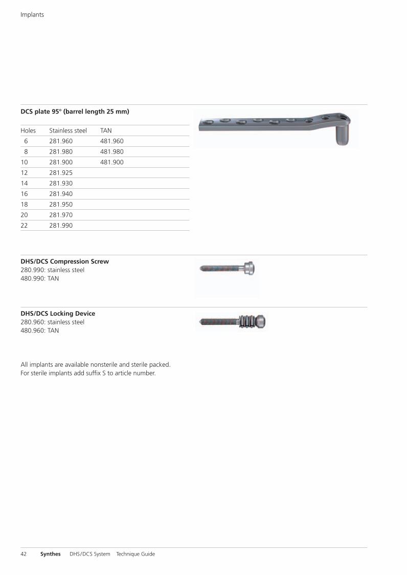
DCS plate 95° (barrel length 25 mm)
Holes Stainless steel TAN
6 281.960 481.960
8 281.980 481.980
10 281.900 481.900
12 281.925
14 281.930
16 281.940
18 281.950
20 281.970
22 281.990
Implants
DHS/DCS Compression Screw280.990: stainless steel480.990: TAN
DHS/DCS Locking Device280.960: stainless steel480.960: TAN
All implants are available nonsterile and sterile packed.For sterile implants add suffix S to article number.
42 Synthes DHS/DCS System Technique Guide
0X6.000.255_AB.qxp:0X6.000.255_AB 04.12.2008 14:32 Uhr Seite 42
Sets
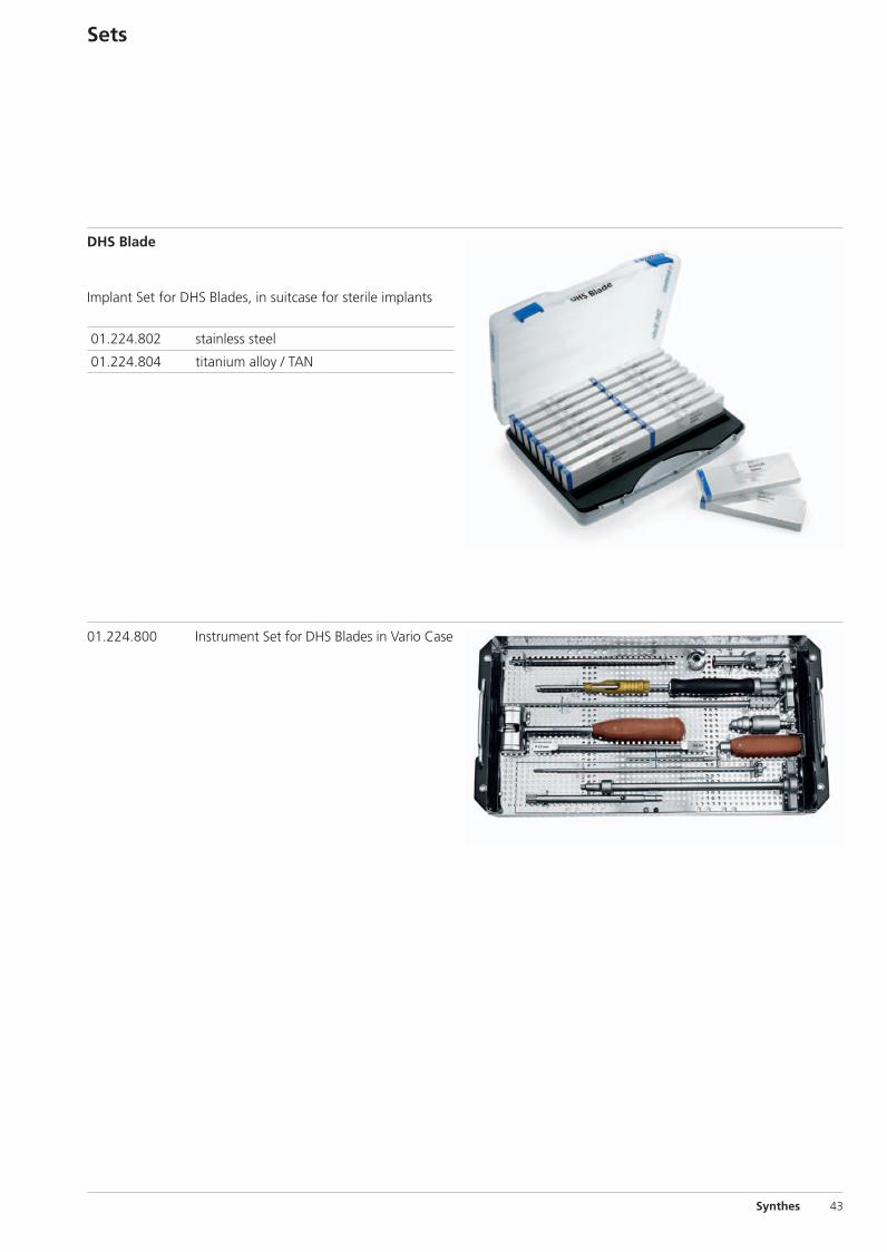
DHS Blade
Implant Set for DHS Blades, in suitcase for sterile implants
01.224.802 stainless steel
01.224.804 titanium alloy / TAN
01.224.800 Instrument Set for DHS Blades in Vario Case
Synthes 43
0X6.000.255_AB.qxp:0X6.000.255_AB 04.12.2008 14:32 Uhr Seite 43
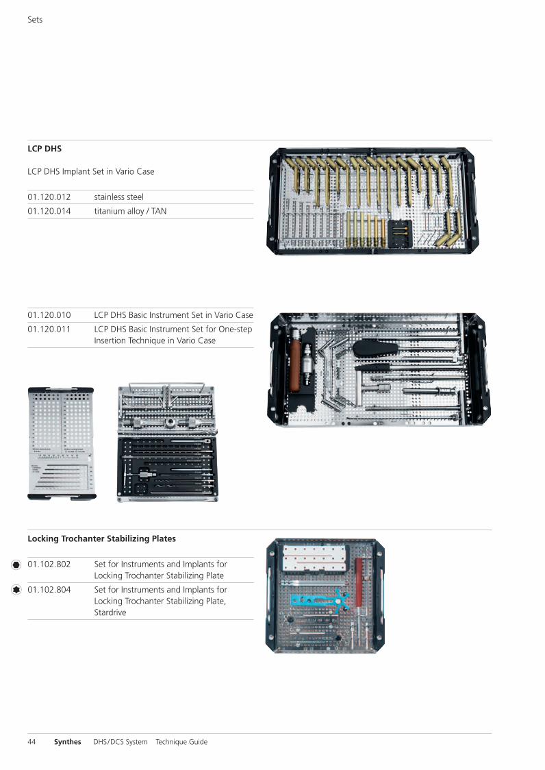
LCP DHS
LCP DHS Implant Set in Vario Case
01.120.012 stainless steel
01.120.014 titanium alloy / TAN
Locking Trochanter Stabilizing Plates
01.102.802 Set for Instruments and Implants forLocking Trochanter Stabilizing Plate
01.102.804 Set for Instruments and Implants forLocking Trochanter Stabilizing Plate,Stardrive
Sets
01.120.010 LCP DHS Basic Instrument Set in Vario Case
01.120.011 LCP DHS Basic Instrument Set for One-stepInsertion Technique in Vario Case
44 Synthes DHS/DCS System Technique Guide
0X6.000.255_AB.qxp:0X6.000.255_AB 04.12.2008 14:32 Uhr Seite 44

Bibliography
1A. Lustenberger et al. (1995) Rotational instability oftrochanteric fractures fixed with the dynamic hip screw.A roentgenographic analysis. Unfallchirurg 95:514-517.
2M. B. Sommers et al. (2004) A laboratory model to evaluatecutout resistance of implants for pertrochanteric fracture fixation. JOT 18:361-368.
3H. W. Jones (2006) Are short femoral nails superior to thesliding hip screw? A meta-analysis of 24 studies involving3279 fractures. Int Orthop. 30(2):69-78.
4M. J. Parker et al. (2006) Gamma and other cephalocondylicintramedullary nails versus extramedullary implants for extra-capsular hip fractures in adults (Cochrane Review). TheCochrane Database of Systematic Reviews, Issue 4.
5Baumgartner et al. (1995) The value of the tip-apex distancein predicting failure of fixation of pertrochanteric fractures ofthe hip. Journal of Bone & Joint Surgery Am. 77:1058-64.
6D. Lorich et al. (2004) Osteoporotic pertrochanteric hip frac-tures – management and current controversies. Journal ofbone & Joint Surgery 2.
7B. Blair et al (1994) Basicervial fractures of the proximal fe-mur: a biomechanical study of 3 internal fixation techniques.Clinical Orthopedics and related research 306:256-263.
8M. J. Parker al. (1998) Choice of implant for internal fixationof femoral neck fractures. Meta-analysis of 25 randomisedtrials including 4925 patients. Acta Orthop Scand. 69(2): 138-43.
9C. Bredahl, et al. (1992) Mortality after hip fracture: resultsof operation within 12 h of admission. Injury 23 (2):83-6.
10W. P. Hamlet et al. (1997) Influence of health status and the timing of surgery on mortality in hip fracture patients. J Orthop 26 (9):621-7.
0X6.000.255_AB.qxp:0X6.000.255_AB 04.12.2008 14:32 Uhr Seite Cvr3

0123 036.
000.
255
SE_
0877
82 A
B 3
1070
038
© S
ynth
es
2007
D
CS,
DH
S, L
CP,
Sta
rdriv
e an
d Va
rio C
ase
are
trad
emar
ks o
f Sy
nthe
s S
ubje
ct t
o m
odifi
catio
ns
Presented by:
Ö036.000.255öAB9ä
0X6.000.255_AB.qxp:0X6.000.255_AB 04.12.2008 14:32 Uhr Seite Cvr4