Embed Size (px)
Citation preview

DEVELOPMENT OF SINGLE STATION LIGHTNING DETECTION SYSTEM
MOHD AZRIN BIN MOHD ARIF FADZILLAH
This thesis is submitted as partial fulfillment of the requirements for the award of the
Bachelor of Electrical Engineering (Power System)
Faculty of Electrical & Electronics Engineering
Universiti Malaysia Pahang
JUNE, 2012

iv
ABSTRACT
The lightning strikes billion of times, kill many of people, and damages
billion of assets per year. This problem may be properly managed by using a
lightning detection system. In this project, the lightning detector circuit was designed
by using PIC16F877A microcontroller. The purposes of this project are to determine
the distance and direction of lightning strikes. One wire antenna and apair of loop
antenna were attached to the circuit. A pair of loop antennas is used to sense the
magnetic field produce by the lightning strike and a wire antenna is used to sense the
electric field produce by the lightning strike. Three variable resistor will act as the
antenna in this project to give the variety input to the PIC microcontroller. CCS
compiler is a software used to write the program to microcontroller. The program
written for Graphic User Interface (GUI) is done by using Microsoft Visual Basic
6.0. LED will blink and LCD will display the data of distance and direction of
lightning strike. Meanwhile, GUI will display the results also with the add on of
electric field and magnetic field values of each antenna and saveall the data in a
laptop.

v
ABSTRAK
Kilat menyerang bilion kali, membunuh ramai orang, dan merosakkan bilion
aset setahun. Masalah ini boleh diatasi dengan menggunakan sistem pengesanan
kilat. Dalam projek ini, litar pengesan kilat telah direka dengan menggunakan
mikropengawal PIC 16F877A. Tujuan projek ini adalah untuk menentukan jarak dan
arah kilat berlaku. Satu wayar antena dan sepasang antena gelung telah dilampirkan
kepada litar. Antena gelung digunakan untuk mengesan hasil medan magnet oleh
kilat dan antena wayar digunakan untuk mengesan medan elektrik yang dihasilkan
oleh kilat. Tiga perintang boleh ubah akan bertindak sebagai antena dalam projek ini
untuk memberi pelbagai input kepada PIC. CCS pengkompil adalah perisian yang
digunakan untuk menulis program untuk mikropengawal. Program yang ditulis untuk
Antara Muka Pengguna Grafik (GUI) dilakukan dengan menggunakan Microsoft
Visual Basic 6.0. LED akan berkelip dan LCD akan memaparkan data jarak dan arah
kilat. Sementara itu, GUI juga akan memaparkan keputusan dengan penambahan
nilai medan elektrik dan medan magnet pada setiap antena dan menyimpan semua
data di dalam komputer riba.

vi
CONTENT
CHAPTER CONTENT PAGE
ACKNOWLEDGEMENT iii
ABSTRACT iv
ABSTRAK v
CONTENT vi
LIST OF TABLES ix
LIST OF FIGURES x
LIST OF ABBREVIATIONS xii
LIST OF APPENDICES xiii
1 INTRODUCTION 1
1.1 Overview 1
1.2 Problem Statements 3
1.3 Project Objective 3
1.4 Project Scope 4
1.5 Thesis Outline 4
2 FUNDAMENTAL OF LIGHTNING 5
2.1 Lightning Phenomenon 5
2.2 How Does Lightning Occur 7
2.3 Types of Lightning 8
2.4 What Happen When People and Lightning Converge 10
2.5 Lightning Strike Locating Technique 11
2.5.1 Determination of Lightning Strike Distance 12
2.5.2 Determination of Lightning Strike Direction13
vii
2.6 Review of previous research 14
2.6.1 Lightning Detection System with Sferics
Observation at a Single Station. 14
2.6.2 Lightning Strike Distance Detector 16
2.6.3 Time-to-Thunder Method of Lightning
Distance Determination 17
2.6.4 World Coverage for Single Station
Lightning Detection 18
2.6.5 Implementation and Use of Lightning
Detection Network in Malaysia 19
2.6.6 Lightning Sensors for Observing, Tracking,
and Nowcasting Severe Weather 20
3 METHODOLOGY 21
3.1 Overview 21
3.2 Equatin Involved 24
3.3 Hardware Requirements 26
3.3.1 Microcontroller 26
3.3.2 UC00A 28
3.3.3 Others Hardware 35
3.3.4 Oscillator 39
3.3.5 Reset Pin 40
3.3.6 PIC16F877A ADC Configuration 42
3.4 Software Requirement 46
3.4.1 CCS C Compiler 46
3.4.2 Microsoft Visual Basic 6 47
3.4.3 Proteus 49
4 RESULT AND DISCUSSIONS 50
4.1 Introduction 50
4.2 LED Output 51
4.3 LCD Output 52
4.4 Data Recorded in Gui 52
4.5 Results Analysis 55

viii
4.6 Discussions 60
5CONCLUSION AND RECOMMENDATIONS 61
5.1 Limitations 61
5.2 Recommendations 62
5.3 Conclusion 63
REFERENCES 64
APPENDIX A 66
APPENDIX B 67
APPENDIX C 73
APPENDIX D 77
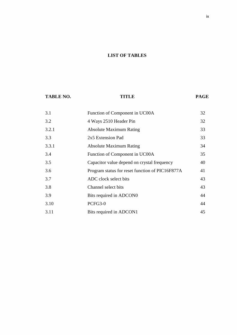
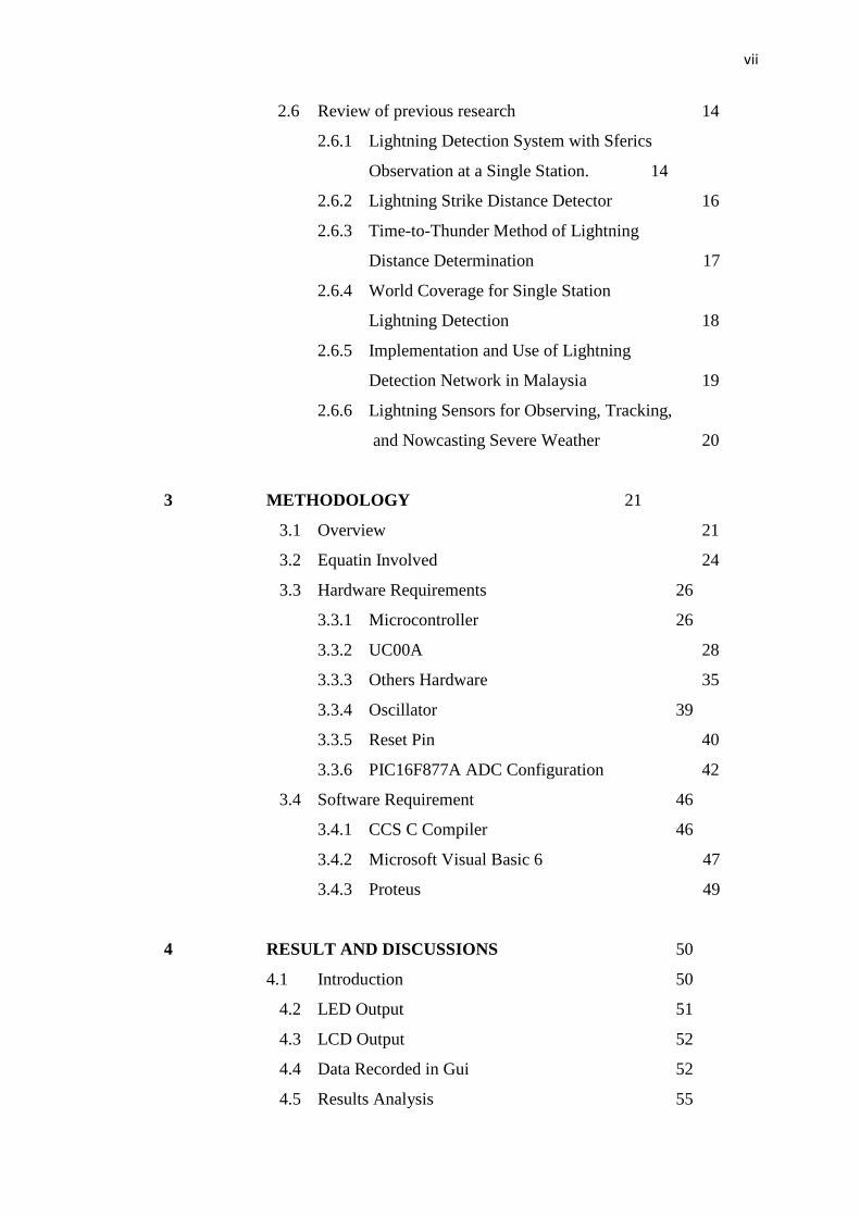
ix
LIST OF TABLES
TABLE NO. TITLE PAGE
3.1 Function of Component in UC00A 32
3.2 4 Ways 2510 Header Pin 32
3.2.1 Absolute Maximum Rating 33
3.3 2x5 Extension Pad 33
3.3.1 Absolute Maximum Rating 34
3.4 Function of Component in UC00A 35
3.5 Capacitor value depend on crystal frequency 40
3.6 Program status for reset function of PIC16F877A 41
3.7 ADC clock select bits 43
3.8 Channel select bits 43
3.9 Bits required in ADCON0 44
3.10 PCFG3-0 44
3.11 Bits required in ADCON1 45

x
LIST OF FIGURES
FIGURE NO. TITLE PAGE
2.1 Volcano Storm 6
2.2 Sheet Lightning 6
2.3 Split Lightning 6
2.4 Desert Storm 6
2.5 Positive Lightning 6
2.6 Circle Strike 6
2.7 Ball Lightning 7
2.8 Multi-Strike 7
2.9 Determination of the Angle to the Lightning Strike Point 13
2.10 Antenna Design 15
2.11 Antenna to Detect Lightning 18
3.1 Block diagram of the project 22
3.2 Hardware of the project 24
3.3 Wire antenna and two orthogonal loop antenna 24
3.4 PIC16F877A pin diagram 26
3.5 Program flow for microcontroller 28
3.6 Traditional method using max232 and db9 29
3.7 Using UC00A method 29
3.8 System overview of UC00A 30
3.9 Connection of UC00A with Laptop 31
3.10 Board Layout of UC00A 31
3.11 Rev 1.0 of UC00A 34
3.12 Rev 1.1 of UC00A 34
3.13 LCD 16x2 35

xi
3.14 LCD Connections with PIC16F877A using Proteus 37
3.15 USB PIC Programmer V2009 37
3.16 Others Hardware Used in The Project 38
3.17 Connection crystal oscillator 39
3.18 ADC flow 42
3.19 Example of Programming in CCS Compiler 47
3.20 Example of Code in VB 6 48
3.21 Example of Object in VB 6 48
3.22 Simulation in Proteus 49
4.1 The hardware of the project 51
4.2 The output displayed at the LCD 52
4.3 Main menu of GUI 53
4.4 Data recorded in GUI 54
4.5 Data save as .txt file 54
4.6 Data obtained from PIC where EF= 10 using Proteus 55
4.7 Data obtained from PIC where EF= 99 using Proteus 56
4.8 Data obtained from PIC where EF= 199 using Proteus 57
4.9 Data obtained from PIC where EF= 255 using Proteus 58
4.10 Data obtained from PIC where E= 10, 255 using VB6 59

xii
LIST OF ABBREVIATIONS
LCD - Liquid Crystal Display
VB - Visual Basic
GUI - Graphic User Interface
CCS - Custom Computer Services
A/D - Analog to digital
PIC - Programmable Interface Controller
MCLR - Master clear
IDE - Integrated Development Environment
HEX - Hexadecimal
OSC - Oscillator
USB - Universal Serial Bus
UART - Universal Asynchronous Receiver/Transmitter
I/O - Input and output
LED - Light-emitting diodes
TOA - Time of Arrival
TX - Transmitter
RX - Receiver
EF - Electric Field
MF1 - Magnetic Field for Loop 1
MF2 - Magnetic Field for Loop 2

xiii
LIST OF APPENDICES
APPENDIX TITLE PAGE
A DATASHEET OF PIC16F87XA 66
B Program Code for PIC16F877A 67
C Program Code for GUI 73
D Schematic Diagram of Lightning Detector 77

CHAPTER 1
INTRODUCTION
1.1 Overview
Lightning is the one of the most unpredictable forces of nature. Any lightning
strike is initializing with the polarization of positive and negative charges within a storm
cloud. Subsequently, the polarization generates electric field surrounding the cloud.
When the electric field generated is strong enough, it will ionize and make the air
become conductive. With the conductive air, [1] charges in the cloud can be transfer to
the ground and hence lightning strike occur.
The lightning discharges radiate electromagnetic pulses in a wide frequency
range from a few Hz up to several hundreds of MHz. Particularly the intense pulses
appearing at very-low-frequency (VLF) are called VLF sferics, which has been used to
remotely detect the location of lightning strike occur. The lightning location such as
theinformation of distance and direction of lightning strike has been performed by multi-
station or single-station technique.

2
Multi-station techniques are the most accurate todetect the location of strike of
lightning which is combining the magnetic direction finding and time-of-arrival
measurements of sferics, as demonstrated by the U.S national lightning detection
network (NLDN) [2]. In 1996, (NLDN) uses 106 sensors that located over the
continental United States to achieve the accuracy of 0.5 km [3].
The single-station techniques use a single VLF receiver and give a more
convenient way to locate the sources [2]. The direction finding will combine with
estimation of the distance to the source. The earliest researches, they use the apparatus
that includes a first loop antenna system for sensing the magnetic field produced by the
lightning which signal is filtered, square rooted, and fed into peak voltage holding
circuit [4]. A second antenna is provided for sensing electric field produced by the
lightning which is fed into filter, an absolute value meter, and to a peak voltage holding
circuit.
In this thesis, the lightning detection system was developed that is simple and
cheaper than lightning detection system owned by Weather Forecasting Company or
some others research company that huge in size and very costly. The method are using
of one wire antenna and a pair of orthogonal loop antenna. The distance and direction
was calculated using of formula deduce from previous researcher. The ratio between
magnetic field and electric field is the method of determining the distance of lightning
strike. The direction of lightning strike was determined by using of inverse tangent
formula. The formulas showed in the next chapter.

3
1.2 Problem Statement
Lightning detector own by Weather Forecasting Company or some others
research company usually very huge in size and costly. So, this kind of lightning
detection system are seldom own by public individual. The information about lightning
strike location is very important for public citizens to avoid them from danger especially
the persons undergoing an outdoor activity. Therefore, to know the location of lightning
strikes occurs, it is often desirable to know the distance and direction. Lightning detector
which able to detect the lightning strike location occurred in a small radius with a small
size and cheaper cost will be the first choice for the public citizens in protecting their life
from the lightning strike.
1.3 Project Objective
There are three objectives in this project which are:
a) To develop portable lightning detector circuit where it is able to determine the
distance and direction of lightning strike.
b) To develop GUI using Microsoft Visual Basic 6.0 to display and record the data.
c) To simulate lightning detection system circuit using Proteus.

4
1.4 Project Scope
In this project, lightning detection system is designed by using PIC16F877A
microcontroller. The software used to write the program to microcontroller is CCS
Compiler whereas the program written for Graphic User Interface (GUI) in between
microcontroller and computer is done by using Visual Basic (VB) 6.0. The circuit of the
project is simulated by using Proteus software. The interfacing between PIC16F877A
and GUI will done through UC00A that is USB to uart converter. Besides data will
display in VB 6, data of lightning strike also are displayed in LCD.All the data storing as
.txt file in the laptop.
1.5 Thesis Outline
This thesis is separated into 5 chapters. Chapter 1focuses on outlines the main
idea of this project. Chapter 2 would explained aboutlightning phenomenon, typical
way of determining the location of lightning strike, and literature review of previous
researcher. Chapter 3woulddescribe the methodology of the project, including the tools,
equipments,procedure and processes involved for the hardware and software
development of theentire project. In chapter 4, results obtained from the lightning
detection system would bediscussed in this chapter. Chapter 5, which is the last chapter,
would make a conclusion for this thesis and recommendations that can be used in further
research related tothis topic in future would be included.

CHAPTER 2
FUNDAMENTAL OF LIGHTNING
2.1 Lightning Phenomenon
Lightning, an awesome and terrifying natural phenomenon, is really nothing
more than an electrical discharge that happens to be at an enormous voltage. The natural
hazard strikes billion of times, kills thousands of people and damages billions of assets
per year. The sheer power of a lightning strike, combined with the brightness and
intensity of the flash that comes with it make it one of the most gorgeous natural
phenomenon in existence. The figures (2.1-2.8) are the most incredible shots of lightning
in nature.

6
Figure 2.1: Volcano Storm Figure 2.2: Sheet Lightning
Figure 2.3:Split Lightning Figure 2.4: Desert Storm
Figure 2.5: Positive Lightning Figure 2.6: Circle Strike

7
Figure 2.7: Ball Lightning Figure 2.8: Multi-Strike
2.2 How Does Lightning Occur
Lightning is the result of a large charge separation within a cloud. Clouds are
composed of millions of ice particles and water droplets. These particles collide with
other condensing moisture as it rises, and when they do, electrons are knocked loose.
These electrons build up at the bottom of a cloud and make it negatively charged. The
rising moisture molecules, now missing electrons, become positively charged and gather
at the top of the cloud. This creates a charge separation, which has an electric field that
is negative at the bottom and positive at the top. As the collisions continue, the electric
field builds so strong that it gives the planet's surface a positive charge. When these
charges become powerful enough, the cloud's electricity is discharged toward the Earth's
surface, which results in lightning.

8
2.3 Types of Lightning
There are various different types of lightning besides the standard cloud to
ground strikes.
a) Cloud to Ground
This is the discharge from the negative lower part of the cloud to the
positively charged earth. This is the most common form thought of when
lightning is mentioned to people however it only constitutes 25% of all lightning
however it is also the type that causes the most damage and so effects our lives
the most.
b) Intracloud Lightning
Intra-cloud lightning is the most common form of lightning. It appears as
a flash within the cloud occurring between the positive and negative charges that
are within the same thunder cloud. Although this is the most common due to it
causing very little danger or damage not alot of research has been carried out on
it in comparison to cloud to ground.

9
c) Intercloud
The least common is the strike between the positive and negative charges
within separate clouds where the strike travels in the between them.
d) Ball Lightning
This appears in the form of a glowing sphere which drifts horizontally in
the air usually only lasting a few seconds. It is still not fully understood why this
occurs, one interesting theory that was recently found was by Abrahamson and
Dinniss in 2000 is to do with the soil type at the place of the strike. This idea
comes in three parts.
i. A heated mixture with more carbon content than silicon can cause the
silicon to separate out into a very light fluffy form which is capable of
floating in air.
ii. The temperature of approximately 3000C where the lightning strikes.
iii. The mixture of carbon and silicon found in the soil.
So, bearing in mind the previous elements if lightning strikes in an area
where the soil has the correct make up then a ball of silicon would be created and
due to its light nature would hover in the air. The light emitted then is believed
to be the oxidization of the silicon which would explain why the ball gives off
such light and the fades away, as this would occur when the oxidization is
complete.

10
2.4 What Happen When People and Lightning Converge
Men are struck by lightning four times more often than women. According to a
study by Ronald L. Holle and Raúl E. López of the National Severe Storms Laboratory
and E. Brian Curran of the National Weather Service from 1959 – 1994, males account
for 84% of lightning fatalities and 82% of injuries, men can take comfort in the fact that
the actual number of deaths and injuries from lightning strikes has decreased in the past
35 years.
Holle's team attributes 30 percent of the decrease in lightning deaths to
improvedforecasts and warnings, better lightning awareness, more substantial buildings,
and socioeconomic changes. They attribute an additional 40 percent to improved
medical care and communications.
The National Weather Service publication Storm Data recorded 3,239 deaths
and 9,818 injuries from lightning strikes between 1959 and 1994. Still, many doctors do
not fully understand how to treat the injuries of the other 80 percent of lightning victims
who survive a strike. Lightning injuries are not the same as electrical shocks. For one
thing, the contact voltage of a typical industrial electrical shock is 20 to 63 kilovolts,
while a lightning strike delivers about 300 kilovolts.
Industrial shocks rarely last longer than half a second (500 milliseconds) because a
circuit breaker opens or the person is thrown far from the live conductor. Lightning
strikes have an even shorter duration, only lasting up to a few milliseconds. Most of the
current from a lightning strike passes over the surface of the body in a process called
"external flashover."

11
Both industrial shocks and lightning strikes result in deep burns at point of
contact, for industry the points of contact are usually on the upper limbs, hands and
wrists, while for lightning they are mostly on the head, neck and shoulders. Industrial
shock victims sometimes exhibit deep tissue destruction along the entire current path,
while lightning victims’ burns seem to center at the entry and exit points. Both industrial
shock and lightning victims may be injured from falling down or being thrown and the
leading cause of immediate death for both is cardiac or cardiopulmonary arrest.
If you survive a shock, you still have to deal with the consequences of the
electrical burns. Industrial shock burns can lead to kidney failure, infection, muscle and
tissue damage, or amputation. Lightning burns are exceptionally life threatening. 70
percent of lightning survivors experience residual effects, most commonly affecting the
brain (neuropsychiatric, vision and hearing). These effects can develop slowly, only
becoming apparent much later
2.5 Lightning Strike Locating Technique
Electrostatic field is generated when lightning striking on the ground due to the
existing of electric charges. Electromagnetic field will generated with the moving
electron which travels from the cloud to the ground. There are a lot research had been
done on determination of lightning strike location. Basically, most of the researches are
started by detecting the electrostatic field and electromagnetic field generated by the
lightning strike. Besides electrostatic field and electromagnetic field, thunder storm is a
famous characteristic of lightning strike used by the researchers in some lightning strike

12
locating systems. There are two parameters need to be determined in order to locate
lightning strike location which are the lightning strike distance and its direction.
2.5.1 Determination of Lightning Strike Distance
The lightning strike distance can be determined by two methods that is by using
delay in time of arriving technique (TOA) and ratio between electromagnetic field and
electrostatic field. The TOA method is implemented by using two kinds of antennas
which are wire antenna used to sense the electrostatic wave and the acoustic antenna is
used to sense the pressure wave produce by the thunder storm when lightning strike to
the ground. The pressure wave produces by the thunder storm is propagating with the
average speed of around 350 m/s while the electrostatic wave is propagating with the
speed of light. The delay in time for the acoustic antenna to sense the pressure wave
compare with the wire antenna to sense electrostatic wave can be used to calculate the
distance of lightning strike by the following formula by assuming the speed of
electrostatic wave is very fast compare with the speed of thunder storm:
D= VT x TD(1)

13
where ,
D = distance of the antenna in meter
V = average speed of thunder storm which is 350 m/s
T = time delay between acoustic antenna and wire antenna in second
The method to detect lightning strike occurred using the ratio between
electromagnetic field and electrostatic field consist a pairs of loop antennas and a wire
antenna. A pairs of loop antenna is used to sense the magnetic field produce by the
lightning strike and a wire antenna is used to sense the electric field produce by the
lightning strike. Next, these two signals are then fed into a ratio meter to get the signal
which is the ratio of the two input signal. The output signal from the ratio meter is
proportional to the distance of the lightning strike.
2.5.2 Determination of Lightning Strike Direction
Figure 2.9: Determination of the Angle to the Lightning Strike Point