Embed Size (px)
Citation preview
DEVELOPMENT OF NAVEGATION SYSTEM FOR VISUALLY IMPAIRED PERSON
DEVELOPMENT OF NAVIGATION SYSTEM FOR VISUALLY IMPAIRED PERSON
A Thesis Submitted in Partial Fulfillment of the Requirements for the Degree of Bachelor of Science in Electrical and Electronics and Engineering
DEPARTMENT OF ELECTRICAL AND ELECTRONICS ENGINEERING BRAC UNIVERSITY
BANGLADESH
December 2012

DEVELOPMENT OF NAVEGATION SYSTEM FOR VISUALLY IMPAIRED PERSON
APPROVAL
The Thesis Report “DEVELOPMENT OF NAVIGATION SYSTEM FOR VISUALLY IMPAIRED PERSON” submitted by Rajesh Kumar Saha,Niaz Mahmud,Sraboni Rahman,Ridwan Bin Zafar to the Department of Electrical and Electronics Engineering, BRAC University Bangladesh, has been accepted as satisfactory for the partial fulfillment of the requirements for the degree of Bachelor of Science (Hons) in Electrical and Electronics Engineering and approved as to its style and contents.
…………………………
(Dr. Mohammed Belal Hossain Bhuian)
Supervisor
DEVELOPMENT OF NAVEGATION SYSTEM FOR VISUALLY IMPAIRED PERSON
DECLARATION
We, hereby, declare that the work presented in this Thesis Project is the outcome of the investigation performed by us under the supervision of Dr. Mohammed Belal Hossain Bhuian as Supervisor and Syed Shakib Sarwar as Co-advisor, Department of Electrical and Electronics Engineering, Brac University Bangladesh. We also declare that no part of this Thesis and thereof has been or is being submitted elsewhere for the award of any degree or Diploma.
Signature by Signature
………………………… …….………………………..
(Dr. Mohammed Belal Hossain Bhuian)
Rajesh Kumar Saha(ID-09221025)
Supervisor
.............................................
Signature by Niaz Mahmud(ID-09221081)
...................................
( Sayed Shakib Sarwar) …………...……………………
Co-supervisor
Ridwan Bin Zafar(ID-09221227)
…….………………………..
Sraboni Rahman(ID-09221236)

DEVELOPMENT OF NAVEGATION SYSTEM FOR VISUALLY IMPAIRED PERSON
ACKNOWLEDGEMENTS
First of all we would like to thank the almighty ALLAH. Today we are successful in completing our work with such ease because He gave us the ability, chance, and cooperating supervisor. We would like to take the opportunity to express our gratitude to respected supervisor Dr. Mohammed Belal Hossain Bhuian for his patience, support and guidance patience assistance. He not only gave us time but also proper guidance and valuable advice whenever we faced with some difficulties. His comments and guidance helped us in preparing our thesis report. We would like to thank Syed Shakib Sarwar as Co-supervisor, for his assistance throughout our project. Our teacher, who inspired me in every steps. We also thankful to our classmate and seniors who helped us in a number of ways by providing various resources and moral support. Last of all we are very grateful to our family and friends for their unconditional love and selfless support.
DEVELOPMENT OF NAVEGATION SYSTEM FOR VISUALLY IMPAIRED PERSON
ABSTRACT
Blindness is one of the most severe types of disability that a person has to endure. Traditionally blind
people use white canes which are very limited in its ability to provide navigation properties to the user
and cannot easily detect obstacles. Mobility of visually impaired people is limited by their inability to
perceive their surroundings. This renders their life to depend on some kind of aid to move around. In this
project we propose to build a navigation system that will be able to guide a visually impaired person
safely and with ease in an indoor and outdoor environment. This goal has been realized through the use of
an ultrasonic device as transmitter and detector to determine the range of obstacles and also
microcontroller. The system includes a warning system through voice alert and through generation of
vibration.
[Pick the date] DEVELOPMENT OF NAVEGATION SYSTEM FOR VISUAL IMPAIR PERSON
2
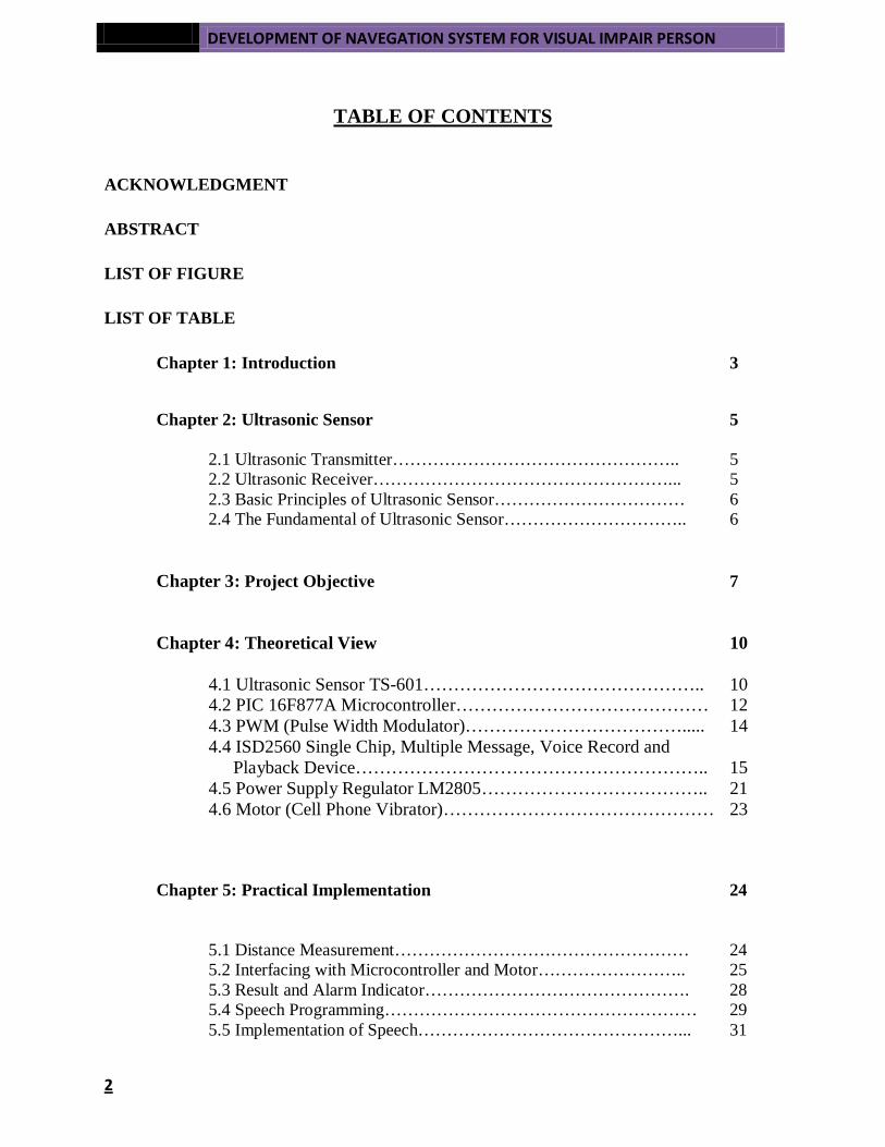
TABLE OF CONTENTS
ACKNOWLEDGMENT
ABSTRACT
LIST OF FIGURE
LIST OF TABLE
Chapter 1: Introduction 3
Chapter 2: Ultrasonic Sensor 5
2.1 Ultrasonic Transmitter………………………………………….. 5 2.2 Ultrasonic Receiver……………………………………………... 5
2.3 Basic Principles of Ultrasonic Sensor…………………………… 6 2.4 The Fundamental of Ultrasonic Sensor………………………….. 6 Chapter 3: Project Objective 7 Chapter 4: Theoretical View 10
4.1 Ultrasonic Sensor TS-601……………………………………….. 10 4.2 PIC 16F877A Microcontroller…………………………………… 12 4.3 PWM (Pulse Width Modulator)………………………………..... 14 4.4 ISD2560 Single Chip, Multiple Message, Voice Record and Playback Device………………………………………………….. 15 4.5 Power Supply Regulator LM2805……………………………….. 21 4.6 Motor (Cell Phone Vibrator)……………………………………… 23
Chapter 5: Practical Implementation 24
5.1 Distance Measurement…………………………………………… 24 5.2 Interfacing with Microcontroller and Motor…………………….. 25 5.3 Result and Alarm Indicator………………………………………. 28 5.4 Speech Programming……………………………………………… 29 5.5 Implementation of Speech………………………………………... 31

DEVELOPMENT OF NAVEGATION SYSTEM FOR VISUALLY IMPAIRED PERSON
5.6 Result and Output Wave Shape of the Speech…………………... 33
Chapter 6: Improvement and Future Plan 35
6.1 Scope for Improvement……………………………………………. 35 6.2 An Outline of Future Work……………………………………….. 35-36
Conclusion 37
Appendix-A 38-43
Appendix-B 44-45
Reference 46-47

DEVELOPMENT OF NAVEGATION SYSTEM FOR VISUALLY IMPAIRED PERSON
LIST OF FIGURES
2.1 Ultrasonic Sonar Transmitter and Receiver……………………………………………….. 5
2.2 Sonic Behavior…………………………………………………………………………….. 6
3.1 Block Diagram of the System……………………………………………………………… 7
3.2 Flow Chart of the System of the Project…………………………………………………… 8
3.3 Practical Implementation of the Navigation System………………………………………. 9
4.1 Ultrasonic Sensor…………………………………………………………………………... 10
4.2 Length and Amplitude………………………………………………………………........… 10
4.3 Sonar Angle………………………………………………………………………………… 10
4.4 Sonar Transmitter and Receiver……………………………………………………………. 11
4.5 Microcontroller (PIC16F877A) Pin Diagram………………………………………………. 12
4.6 PWM Signal………………………………………………………………………………… 14
4.7 ISD2560 Pin Configuration…………………………………………………………………. 15
4.8 Block Diagram of ISD2560…………………………………………………………………. 15
4.9 Voltage Regulator Pin Out………………………………………………………………….. 21
4.10 Voltage Regulator Circuit………………………………………………………………….. 22
4.11 Motor Circuit………………………………………………………………………………. 23
5.1 Distance Measurement………………………………………………………………………. 25
5.2 Distance Measurement………………………………………………………………………. 25
5.3 Two Sensors Interfaced with PIC16F877A and Alarm Circuit…………………………… 26
5.4 Sensor Detect Obstacle, Both Light Glow………………………………………………… 28
5.5 First Sensor Detects Obstacle, Green Light Glow……………………………………………28
5.6 Second Sensor Detects Obstacle, Red Light Glow…………………………………………...28
5.7 Speech Circuit (ISD2560)…………………………………………………………………….29
5.8 Interface the Speech Circuit with Microcontroller and Other Circuit Shown Above………..31
5.9 Overall Circuit Diagram Between Sensor, Speech, Microcontroller and Motor……………..32
5.10 Wave Shape when Detects Obstacle in Left (Says ‘Bame Badha’)…………………………33
5.11 Wave Shape when Detects Obstacle in Right (Says ‘Dane Badha’)………………………..33
5.12 Wave Shape when Detects Obstacle Infront (Says ‘Samne Badha’)……………………….34
6.1 RFID System…………………………………………………………………………………36
6.2 Global Position System ………………………………………………………………………36

DEVELOPMENT OF NAVEGATION SYSTEM FOR VISUALLY IMPAIRED PERSON
LIST OF TABLES
1.1 Passive Component Uses Application in Speech Circuit………………………………… 16
1.2 Operational Mode Application…………………………………………………………… 18
1.3 Push-Button Mode…………………………………………………………………………19.
1.4 Pins Used to Generate Speech…………………………………………………………… 30-31

DEVELOPMENT OF NAVIGATION SYSTEM FOR VISUALLY IMPAIRED PERSON
Page | 1

2
DEVELOPMENT OF NAVIGATION SYSTEM FOR VISUALLY IMPAIRED PERSON
Page | 3
CHAPTER-1
With the recent fast growing technology and so many resources available, researches have been
conducted on building a navigation system for the visually impaired people in order to aid them in a more
independent way. Many students around the world have been putting their ideas forth in order to develop
a system for both the outdoor and the indoor environment.
Introduction:
In recent years many papers have been researched on:-
• Pathfinder A handheld device for detecting obstructions in the path of the blind and
visually impaired[Project by Kyle Boyace]
• VI-Navi: a novel indoor navigation system for visually impaired people[Project by-
Parth Mehta]
• An Ultrasonic Navigation System for Blind People [Project by -Bousbia Saleh]
• Blind Audio Guidance System[Project by -Brey Danels, Oluakode Ogunmakin, George Agollah, Eric Worley]
• Drishti: An Integrated Indoor/Outdoor Blind Navigation System and Service[Project by- Lisa Ran, Sumi Helal and Steve Moore]
• Navigation System for the Blind:Auditory Display Modes and Guidance[Project by -
Jack M. Loomis, Reginald G. Golledge, Roberta L. Klatzky]
• INDOOR NAVIGATION SYSTEM FOR VISUALLY IMPAIRED PERSON USING GPS[Project by -Dr. Boyina.S.Rao, Ms. K.Deepa, Hari Prasanth.L, Vivek.S, Nanda Kumar.S,Rajendhiran.A, Saravana.J]
Our thesis will be based on developing a system having microcontroller with speech output. This
navigation system has two distinct components: detecting obstacles and alerting the person by means of
vibration and voice command. So our goal is to construct a portable simple less costly device that will
help visually impaired people to move in familiar and unfamiliar environments.
DEVELOPMENT OF NAVIGATION SYSTEM FOR VISUALLY IMPAIRED PERSON
Page | 4
Throughout the thesis our mission is to carry out the following functions.
• Implement the use of Microcontroller.
• Detection of obstacles using ultrasonic sensors
• Implement ISD2560 ChipCorder and introduce voice alert to the system.
• Implement required electronic components such as transistors, voltage regulators.
Short briefing of our project can be describe as
• Chapter 1- This chapter reviews the basic and fundamental concept of Ultrasonic Sensor
• Chapter 2-This chapter reviews Our Project Objective
• Chapter 3-This chapter reviews some of the work related to the study of the ultrasonic. The
main reviews are ultrasonic sensor, PIC microcontroller, ISD2560, Motor (Cell phone
Vibrator) and Power Supply regulator.
• Chapter 4- This chapter reviews the Practical Implementation of our Project.
• Chapter 5- This chapter reviews the Scope for Improvement of this Project and Our Future plan
DEVELOPMENT OF NAVIGATION SYSTEM FOR VISUALLY IMPAIRED PERSON
Page | 5
CHAPTER-2
ULTRASONIC SENSOR
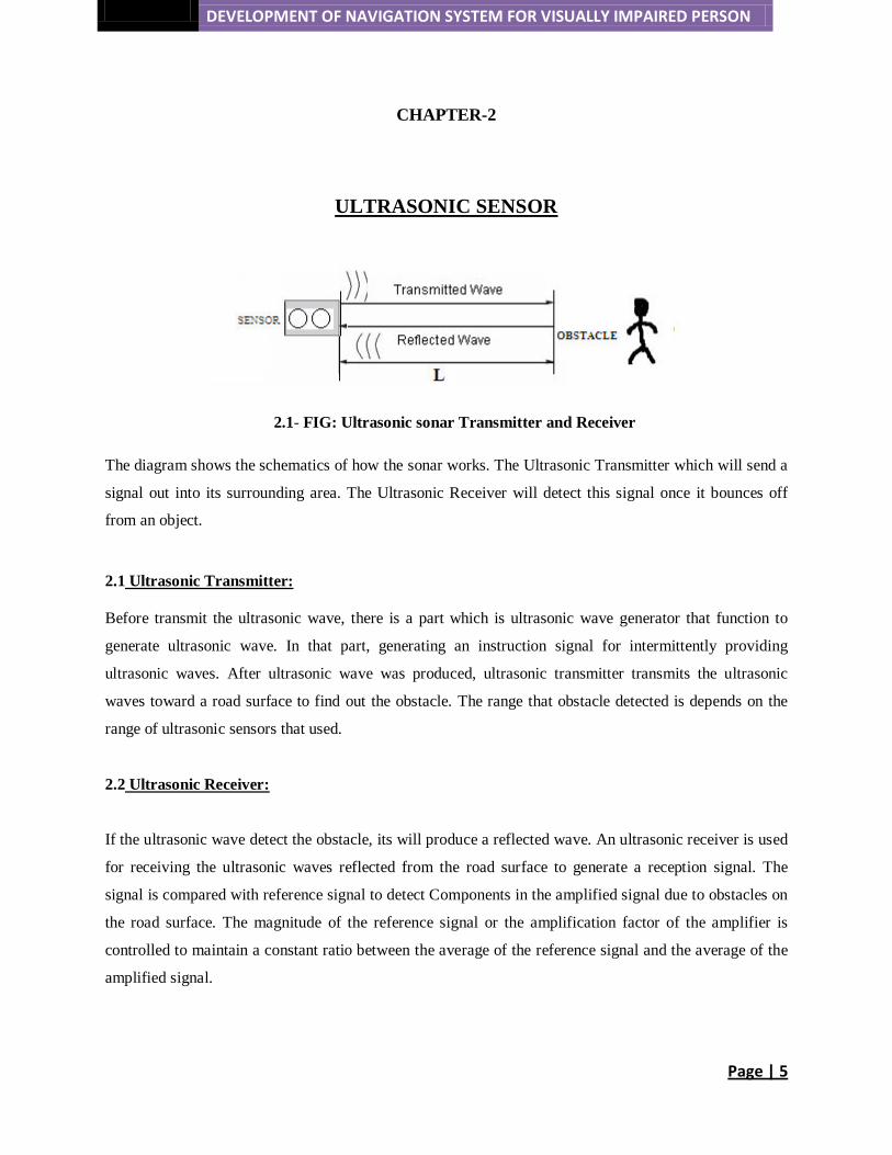
2.1- FIG: Ultrasonic sonar Transmitter and Receiver
The diagram shows the schematics of how the sonar works. The Ultrasonic Transmitter which will send a
signal out into its surrounding area. The Ultrasonic Receiver will detect this signal once it bounces off
from an object.
2.1
Ultrasonic Transmitter:
Before transmit the ultrasonic wave, there is a part which is ultrasonic wave generator that function to
generate ultrasonic wave. In that part, generating an instruction signal for intermittently providing
ultrasonic waves. After ultrasonic wave was produced, ultrasonic transmitter transmits the ultrasonic
waves toward a road surface to find out the obstacle. The range that obstacle detected is depends on the
range of ultrasonic sensors that used.
2.2
Ultrasonic Receiver:
If the ultrasonic wave detect the obstacle, its will produce a reflected wave. An ultrasonic receiver is used
for receiving the ultrasonic waves reflected from the road surface to generate a reception signal. The
signal is compared with reference signal to detect Components in the amplified signal due to obstacles on
the road surface. The magnitude of the reference signal or the amplification factor of the amplifier is
controlled to maintain a constant ratio between the average of the reference signal and the average of the
amplified signal.
DEVELOPMENT OF NAVIGATION SYSTEM FOR VISUALLY IMPAIRED PERSON
Page | 6
2.3 Basic Principle of Ultrasonic Sound:
Ultrasonic sensing techniques have become mature and are widely used in the various fields of
engineering and basic science. One of advantages of ultrasonic sensing is its outstanding capability to
probe inside objects nondestructively because ultrasound can propagate through any kinds of media
including solids, liquids and gases except vacuum. In typical ultrasonic sensing the ultrasonic waves are
travelling in a medium and often focused on evaluating objects so that useful information on the
interaction of ultrasonic energy with the objects are acquired as ultrasonic signals that are in wave forms
variations with transit time. Ultrasound waves are generated by piezoelectric crystals. Piezoelectric means
"pressure electric" effect. When an electric current is applied to a quartz crystal, its shape changes with
polarity. This causes expansion and contraction that in turn causes compression and rarefaction of sound
waves. Many animals have the ability to hear sounds in the human ultrasonic frequency range.
2.4
The Fundamental of Ultrasonic Sensor:
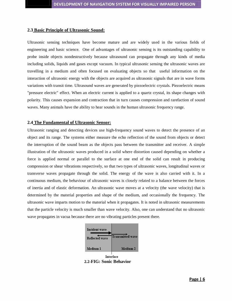
Ultrasonic ranging and detecting devices use high-frequency sound waves to detect the presence of an
object and its range. The systems either measure the echo reflection of the sound from objects or detect
the interruption of the sound beam as the objects pass between the transmitter and receiver. A simple
illustration of the ultrasonic waves produced in a solid where distortion caused depending on whether a
force is applied normal or parallel to the surface at one end of the solid can result in producing
compression or shear vibrations respectively, so that two types of ultrasonic waves, longitudinal waves or
transverse waves propagate through the solid. The energy of the wave is also carried with it. In a
continuous medium, the behaviour of ultrasonic waves is closely related to a balance between the forces
of inertia and of elastic deformation. An ultrasonic wave moves at a velocity (the wave velocity) that is
determined by the material properties and shape of the medium, and occasionally the frequency. The
ultrasonic wave imparts motion to the material when it propagates. It is noted in ultrasonic measurements
that the particle velocity is much smaller than wave velocity. Also, one can understand that no ultrasonic
wave propagates in vacua because there are no vibrating particles present there.
2.2-FIG: Sonic Behavior

DEVELOPMENT OF NAVIGATION SYSTEM FOR VISUALLY IMPAIRED PERSON
Page | 7
CHAPTER-3
The source battery is of 9V. Our system required 5V input. In order to bring down the voltage we
implemented a voltage regulator circuit using LM7805. We have put in a switch in the system. After
turning on the switch, the regulated power is transmitted to the circuit board for functioning of all the
components. The motor requires 1.3V. The 5V input supplied is reduced to this level by means of a
resistor and transistor.
PROJECT OBJECTIVE
We are contemplating in creating a system that will guide a visually impaired person to move around
efficiently and independently. We have used the ultrasonic sensor TS601, which will detect the barriers
in the path. PIC 16F877A microcontroller that works on code language has been used to measure the
distance between the person and the obstacle, connects with the motor circuit to act as an alert system and
also interface with ISD 2560 to produce a speech output so that the person can know the direction of the
obstacle.
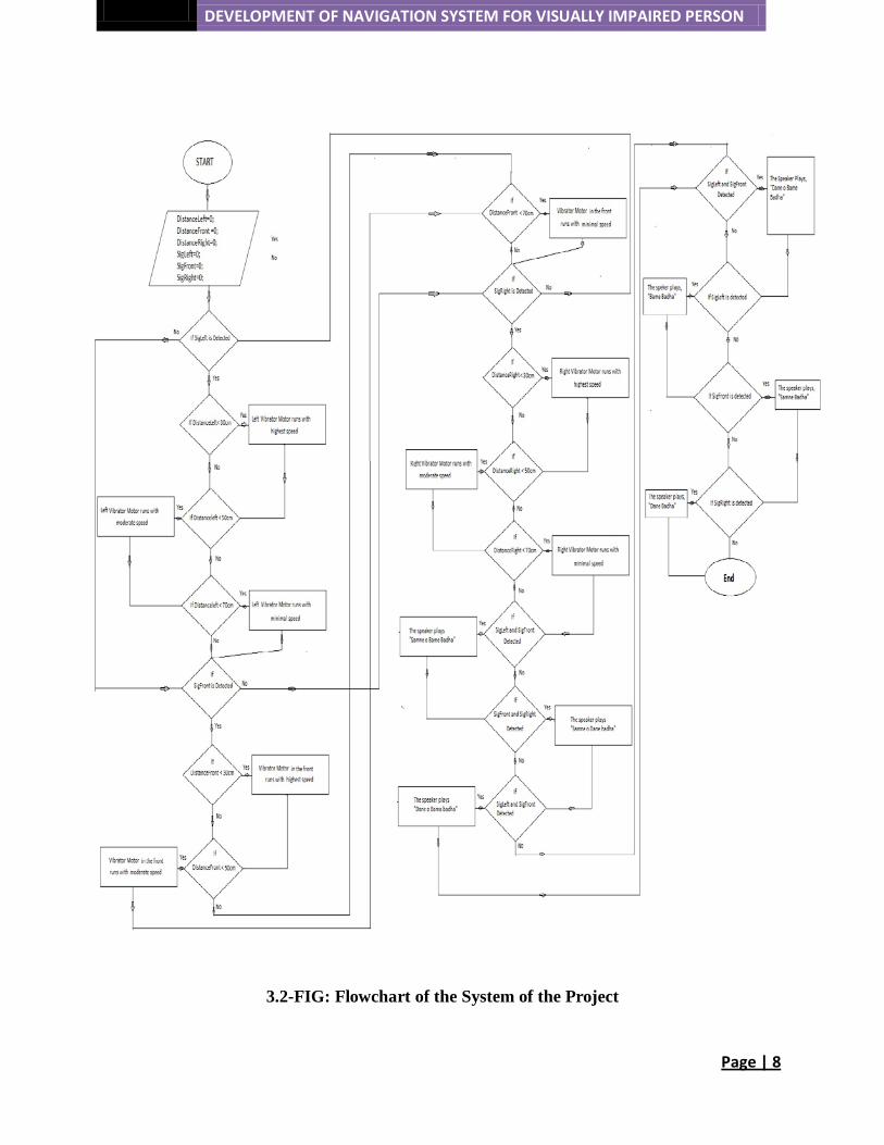
We have used three sensors and three vibrators (motor) in the circuit. Whenever any of the three sensors
separately or together detect obstacles, the signal passes onto the microcontroller. The code that is set in
the microcontroller works under condition which when fulfilled interfaces with the motor circuit (motor
of a cell phone) and the ISD IC to produce vibrations (motor circuit) and speech output (ISD).
3.1-FIG: Block Diagram of the System
DEVELOPMENT OF NAVIGATION SYSTEM FOR VISUALLY IMPAIRED PERSON
Page | 8
3.2-FIG: Flowchart of the System of the Project

DEVELOPMENT OF NAVIGATION SYSTEM FOR VISUALLY IMPAIRED PERSON
Page | 9
3.3-FIG: Practical Implementation of the Navigation System
DEVELOPMENT OF NAVIGATION SYSTEM FOR VISUALLY IMPAIRED PERSON
Page | 10
CHAPTER-4
4.1
THEORITICAL VIEW
ULTRASONIC SENSOR-TS601:
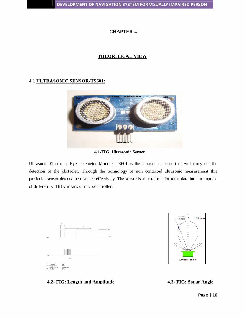
4.1-FIG: Ultrasonic Sensor
Ultrasonic Electronic Eye Telemeter Module, TS601 is the ultrasonic sensor that will carry out the
detection of the obstacles. Through the technology of non contacted ultrasonic measurement this
particular sensor detects the distance effectively. The sensor is able to transform the data into an impulse
of different width by means of microcontroller.
4.2- FIG: Length and Amplitude 4.3- FIG: Sonar Angle

DEVELOPMENT OF NAVIGATION SYSTEM FOR VISUALLY IMPAIRED PERSON
Page | 11
A square pulse is triggered and the ultrasonic transmitter sends out a signal at an angle of 45 degree.
Obstacles within this range are detected and the signal is sent back to the ultrasonic receiver. The square
impulse is given to the SIG pin of the ultrasonic sensor. The electrical level of the SIG line rises as
shown by T1. This triggers a range of 40 kHz signals. The receiving pulse will come back to the output
pin after 200us. When there is an object the sensor will send back the signal that is indicated by T3. As
there is no object the signal descends to low value.
The minimum distance at which the sensor detects the obstacle is 10cm and the maximum distance is
290cm.
4.4- FIG: Sonar Transmitter and Receiver
• Application: Distance measurement
FEATURES:
• Range of measurement (from datasheet): 0.03M ~ 3M
• Output: impulse width
• Rated working voltage: 5V
• Working current : < 15mA
• Frequency of Sensor: 40 kHz
• Response Time: 5ms
• Angle for detection : 45 Degree
DEVELOPMENT OF NAVIGATION SYSTEM FOR VISUALLY IMPAIRED PERSON
Page | 12
4.2 PIC16F877A MICROCONTROLLER
:
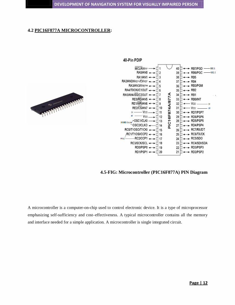
4.5-FIG: Microcontroller (PIC16F877A) PIN Diagram
A microcontroller is a computer-on-chip used to control electronic device. It is a type of microprocessor
emphasizing self-sufficiency and cost–effectiveness. A typical microcontroller contains all the memory
and interface needed for a simple application. A microcontroller is single integrated circuit.
DEVELOPMENT OF NAVIGATION SYSTEM FOR VISUALLY IMPAIRED PERSON
Page | 13
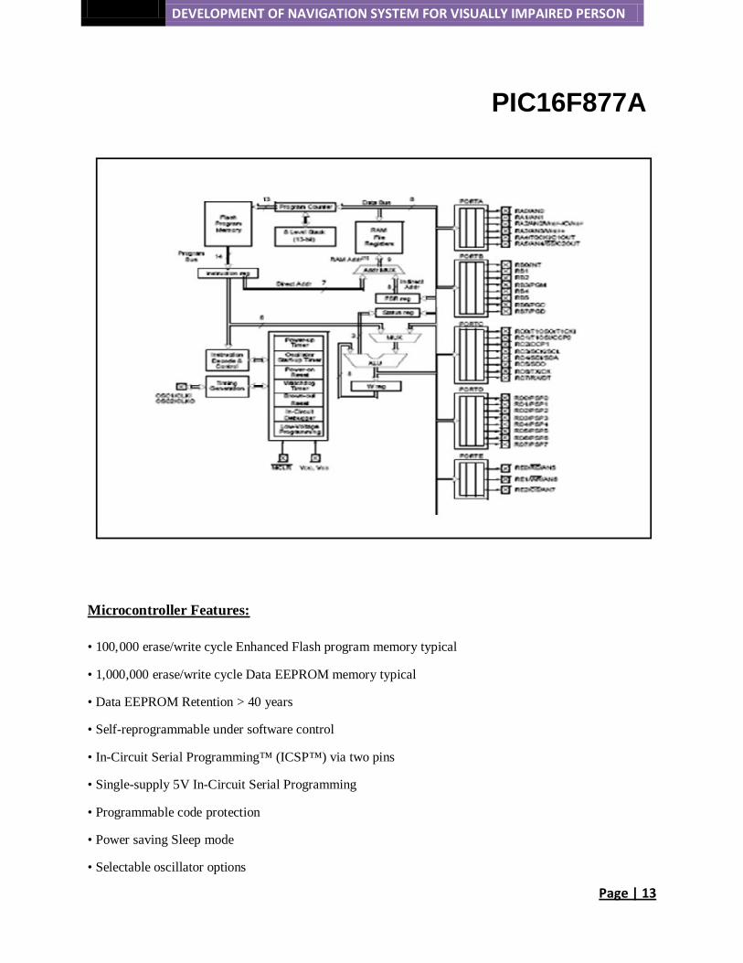
PIC16F877A
• 100,000 erase/write cycle Enhanced Flash program memory typical
Microcontroller Features:
• 1,000,000 erase/write cycle Data EEPROM memory typical
• Data EEPROM Retention > 40 years
• Self-reprogrammable under software control
• In-Circuit Serial Programming™ (ICSP™) via two pins
• Single-supply 5V In-Circuit Serial Programming
• Programmable code protection
• Power saving Sleep mode
• Selectable oscillator options
DEVELOPMENT OF NAVIGATION SYSTEM FOR VISUALLY IMPAIRED PERSON
Page | 14
• Timer 0: 8-bit timer/counter with 8-bit prescaler
Peripheral Features:
o Timer 1: 16-bit timer/counter with prescaler, can be incremented during Sleep via external crystal/clock
o Timer2: 8-bit timer/counter with 8-bit period register, prescaler and postscaler
o Two Capture, Compare, PWM modules
- Capture is 16-bit, max. Resolution is 12.5 ns
- Compare is 16-bit, max. Resolution is 200 ns
- PWM max. Resolution is 10-bit
4.3
.
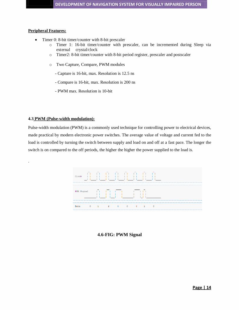
PWM (Pulse-width modulation):
Pulse-width modulation (PWM) is a commonly used technique for controlling power to electrical devices,
made practical by modern electronic power switches. The average value of voltage and current fed to the
load is controlled by turning the switch between supply and load on and off at a fast pace. The longer the
switch is on compared to the off periods, the higher the higher the power supplied to the load is.
4.6-FIG: PWM Signal

DEVELOPMENT OF NAVIGATION SYSTEM FOR VISUALLY IMPAIRED PERSON
Page | 15
4.4 ISD2560 SINGLE CHIP, MULTIPLE MASSAGE VOICE RECORD AND PLAYBACK DEVICE
4.7-FIG: ISD2560 PIN CONFIGURE
4.8- FIG: BLOCK DIAGRAM OF ISD2560

DEVELOPMENT OF NAVIGATION SYSTEM FOR VISUALLY IMPAIRED PERSON
Page | 16
1.1-TABLE: PASSIVE COMPONENT USES APPLICATION IN SPEECH CIRCUIT
Microcontroller Interface:
The use of ISD2560 is very simple and it contains all the necessary interfaces for microcontroller driven
applications. The address and control pins can be connected to a microcontroller, manipulating different
tasks such as message assembly, message concatenation, predefined fixed message segmentation and
message management.
Programming:
The ISD2560 is ideal for playback-only applications. Single or multiple messages are referenced
manually or through a microcontroller. Once the desired message configuration is created, the duplicate
messages can be easily created through programming.

DEVELOPMENT OF NAVIGATION SYSTEM FOR VISUALLY IMPAIRED PERSON
Page | 17
There are two Modes we can operate the ISD2560 device one is operational mode and another is Push-
Button Mode.
Operational Mode:
The ISD2560 is designed with several built-in Operational Modes which can provide maximum
functionalities with usage of minimum external components. These modes are described in details as
below. The Operational Modes are accessed via the address pins. When the two most significant bits
(MSB) A8 and A9 are HIGH, the remaining address signals are interpreted as mode bits and not as
address bits. Secondly, Operational Modes are executed when CE pin goes LOW. This Operational Mode
remains in effect until the next LOW-going CE signal, at which point the current modes are sampled and
executed.
M0 – Message Cueing
Message Cueing allows the user to skip messages without knowing the actual physical addresses of each
message. Each CE-LOW pulse causes the internal address pointer to skip to the next message. This mode
is only used for playback.
M1 – Delete EOM Markers
The M1 Operational Mode allows sequentially recorded message to be combined into a single message.
When the Operational Mode is configured, messages recorded sequentially are played back as one
continuous message.
M2 – Unused
When Operational Modes are selected, the M2 pin should be LOW
M3 – Message Looping
The M3 operational Modes allows the automatic and continuous repeatedly playback of the message
located at the beginning of the address space..
DEVELOPMENT OF NAVIGATION SYSTEM FOR VISUALLY IMPAIRED PERSON
Page | 18
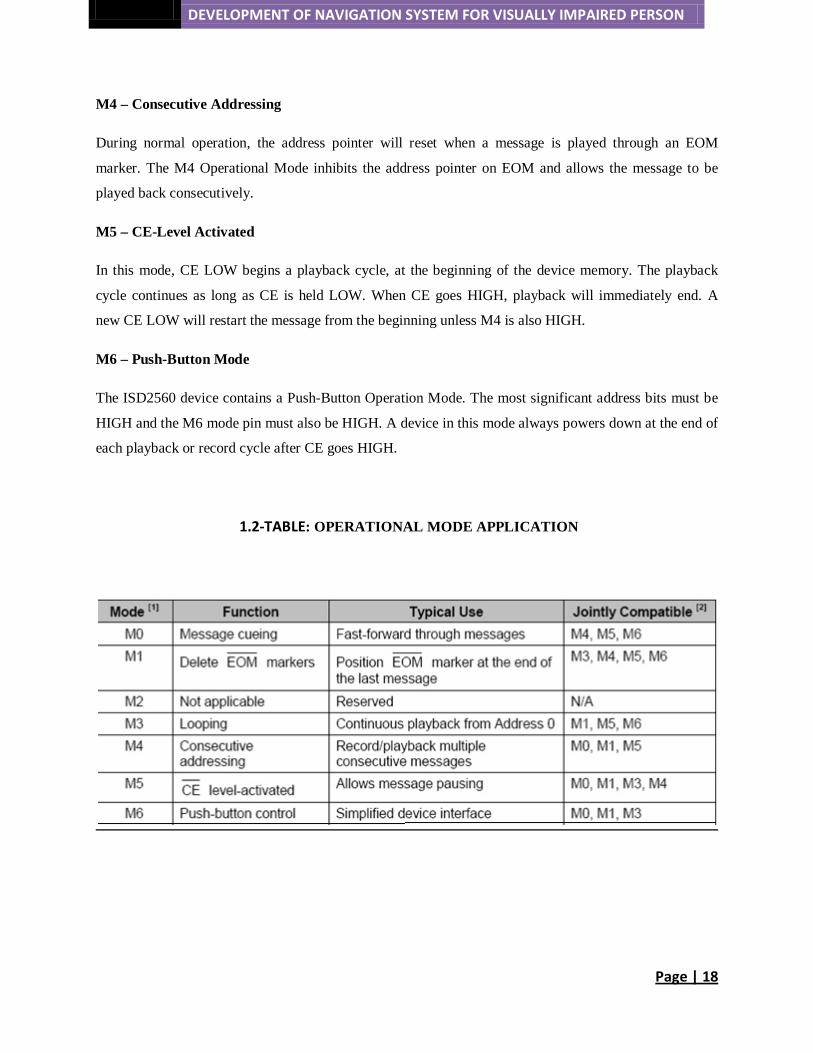
M4 – Consecutive Addressing
During normal operation, the address pointer will reset when a message is played through an EOM
marker. The M4 Operational Mode inhibits the address pointer on EOM and allows the message to be
played back consecutively.
M5 – CE-Level Activated
In this mode, CE LOW begins a playback cycle, at the beginning of the device memory. The playback
cycle continues as long as CE is held LOW. When CE goes HIGH, playback will immediately end. A
new CE LOW will restart the message from the beginning unless M4 is also HIGH.
M6 – Push-Button Mode
The ISD2560 device contains a Push-Button Operation Mode. The most significant address bits must be
HIGH and the M6 mode pin must also be HIGH. A device in this mode always powers down at the end of
each playback or record cycle after CE goes HIGH.
1.2-TABLE: OPERATIONAL MODE APPLICATION
DEVELOPMENT OF NAVIGATION SYSTEM FOR VISUALLY IMPAIRED PERSON
Page | 19
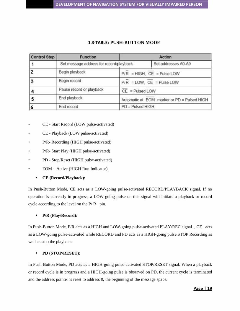
1.3-TABLE: PUSH-BUTTON MODE
• CE - Start Record (LOW pulse-activated)
• CE - Playback (LOW pulse-activated)
• P/R- Recording (HIGH pulse-activated)
• P/R- Start Play (HIGH pulse-activated)
• PD - Stop/Reset (HIGH pulse-activated)
• EOM – Active (HIGH Run Indicator)
CE (Record/Playback):
In Push-Button Mode, CE acts as a LOW-going pulse-activated RECORD/PLAYBACK signal. If no
operation is currently in progress, a LOW-going pulse on this signal will initiate a playback or record
cycle according to the level on the P/ R pin.
P/R (Play/Record):
In Push-Button Mode, P/R acts as a HIGH and LOW-going pulse-activated PLAY/REC signal. , CE acts
as a LOW-going pulse-activated while RECORD and PD acts as a HIGH-going pulse STOP Recording as
well as stop the playback
PD (STOP/RESET):
In Push-Button Mode, PD acts as a HIGH-going pulse-activated STOP/RESET signal. When a playback
or record cycle is in progress and a HIGH-going pulse is observed on PD, the current cycle is terminated
and the address pointer is reset to address 0, the beginning of the message space.
DEVELOPMENT OF NAVIGATION SYSTEM FOR VISUALLY IMPAIRED PERSON
Page | 20
EOM (RUN):
In Push-Button Mode, EOM becomes an active-HIGH RUN signal which can be used to drive an LED
or other external device. It is HIGH whenever a record or playback operation is in progress.
Recording in Push-Button Mode:
1. The PD pin should be LOW, usually using a pull-down resistor.
2. The P/ R pin is taken LOW.
3. The CE pin is pulsed LOW. Recording starts, EOM goes HIGH to indicate an operation in
progress.
4. When the CE pin is pulsed LOW. Recording pauses, EOM goes back LOW. The internal address
pointers are not cleared, but the EOM marker is stored in memory to indicate as the message
end. The P/R pin may be taken HIGH at this time.
Playback in Push-Button Mode:
1. The PD pin should be LOW.
2. The P/ R pin is taken HIGH.
3. The CE pin is pulsed LOW. Playback starts, EOM goes HIGH to indicate an operation in
progress.
4. If the CE pin is pulsed LOW or an EOM marker is encountered during an operation, the part will
pause. The P/ R pin may be changed at this time. A subsequent record operation would not reset
the address pointers and the recording would begin where playback ended.
5. CE is again pulsed LOW. Playback starts where it left off, with EOM going HIGH to indicate an
operation in progress.
6. Pulling CE LOW will reset the address pointer and start playback from the beginning. After a
PD pulse, the part is reset to address 0.
DEVELOPMENT OF NAVIGATION SYSTEM FOR VISUALLY IMPAIRED PERSON
Page | 21
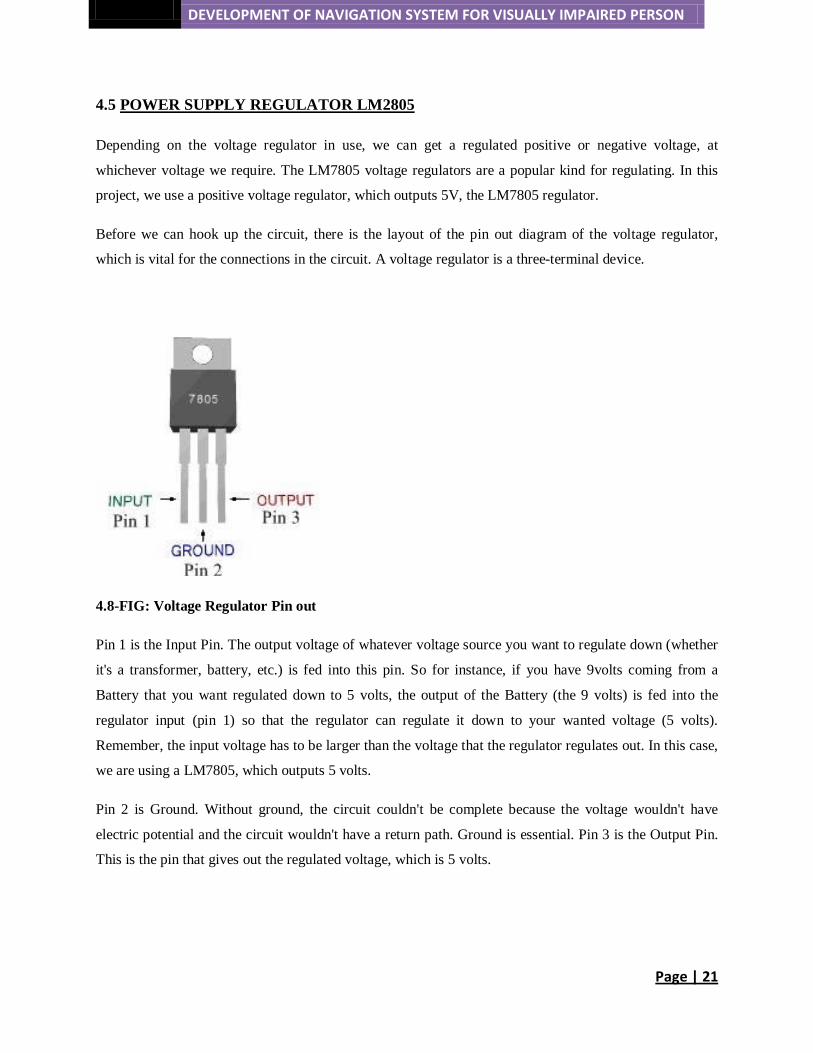
4.5 POWER SUPPLY REGULATOR LM2805
Depending on the voltage regulator in use, we can get a regulated positive or negative voltage, at
whichever voltage we require. The LM7805 voltage regulators are a popular kind for regulating. In this
project, we use a positive voltage regulator, which outputs 5V, the LM7805 regulator.
Before we can hook up the circuit, there is the layout of the pin out diagram of the voltage regulator,
which is vital for the connections in the circuit. A voltage regulator is a three-terminal device.
4.8-FIG: Voltage Regulator Pin out
Pin 1 is the Input Pin. The output voltage of whatever voltage source you want to regulate down (whether
it's a transformer, battery, etc.) is fed into this pin. So for instance, if you have 9volts coming from a
Battery that you want regulated down to 5 volts, the output of the Battery (the 9 volts) is fed into the
regulator input (pin 1) so that the regulator can regulate it down to your wanted voltage (5 volts).
Remember, the input voltage has to be larger than the voltage that the regulator regulates out. In this case,
we are using a LM7805, which outputs 5 volts.
Pin 2 is Ground. Without ground, the circuit couldn't be complete because the voltage wouldn't have
electric potential and the circuit wouldn't have a return path. Ground is essential. Pin 3 is the Output Pin.
This is the pin that gives out the regulated voltage, which is 5 volts.

DEVELOPMENT OF NAVIGATION SYSTEM FOR VISUALLY IMPAIRED PERSON
Page | 22
Build-up of the circuit:
These are the Parts Required to Do So:
-LM7805 Voltage Regulator Chip
-9-volt Battery
-0.10uF Capacitor
-0.1uF Capacitor
4.10-FIG: VOLTAGE REGULATOR CIRCUIT
DEVELOPMENT OF NAVIGATION SYSTEM FOR VISUALLY IMPAIRED PERSON
Page | 23
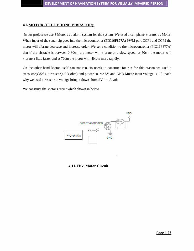
4.6 MOTOR (CELL PHONE VIBRATOR):
In our project we use 3 Motor as a alarm system for the system. We used a cell phone vibrator as Motor.
When input of the sonar sig goes into the microcontroller (PIC16F877A) PWM port CCP1 and CCP2 the
motor will vibrate decrease and increase order. We set a condition to the microcontroller (PIC16F877A)
that if the obstacle is between 0-30cm the motor will vibrate at a slow speed, at 50cm the motor will
vibrate a little faster and at 70cm the motor will vibrate more rapidly.
On the other hand Motor itself can not run, its needs to construct for run for this reason we used a
transistor(C828), a resistor(4.7 k ohm) and power source 5V and GND.Motor input voltage is 1.3 that’s
why we used a resistor to voltage bring it down from 5V to 1.3 volt
We construct the Motor Circuit which shown in below-
4.11-FIG: Motor Circuit

DEVELOPMENT OF NAVIGATION SYSTEM FOR VISUALLY IMPAIRED PERSON
Page | 24
CHAPTER-5
PRACTICAL IMPLEMENTATION
5.1 Distance Measurement:
Our work begins with first understanding the function of the ultrasonic transmitter. In order to understand
its range and the detection of obstacles the following experiment is carried out. Initially a circuit is set up
using an ultrasonic sensor, a microcontroller PIC 16F877A and an LCD display. According to the
datasheet acquired from the internet the circuit is set up by connecting the appropriate wires to the
corresponding pins of the microcontroller. A code is set in the microcontroller.
As per instructed in the micro controller code a square impulse is given to the SIG pin of the ultrasonic
sensor. The electrical level of the SIG line rises when the pulse is given. This triggers a range of 40 kHz
signals. According to the code of the micro controller the receiving pulse will come back to the output pin
after 200us. When there is an object the sensor will send back the signal to the receiver. As there is no
object the signal descends to low value. The pulses have been observed by means of digital oscilloscope.

DEVELOPMENT OF NAVIGATION SYSTEM FOR VISUALLY IMPAIRED PERSON
Page | 25
5.1-FIG: Distance Measurement
The distance is shown in the LCD display. However upon measuring the distance between the object and
the sensor by means of a scale the distance was found to be different. Therefore by calculations a formula
has been derived and put forth in the microcontroller code from where the correct distance between the
sensor and the obstacle can be determined and viewed in the LCD display. The experimental range is
found to be 10cm ~290cm and the signal covers an angle of 45 degree as measured.
5.2-FIG: Distance Measurement
5.2 Interfacing with Microcontroller and Motor:
After deducting the range of the ultrasonic sensor, the LCD display has been removed. A motor circuit is
introduced. A PWM (PULSE WIDTH MODULATION) signal is simply a pulse of varying length. It is
applied in this circuit in order to aid in the motor control. By varying the operating time of the PWM
signal the speed of the motor can increase or decrease depending on how long the pulse is sent to the
motor. In this manner the effective power of the signal varies. The signal generated by the PIC cannot be
DEVELOPMENT OF NAVIGATION SYSTEM FOR VISUALLY IMPAIRED PERSON
Page | 26
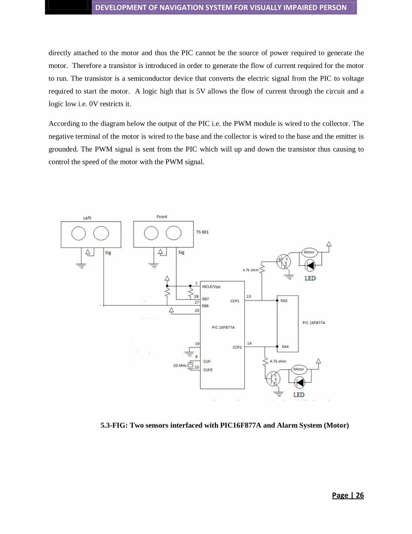
directly attached to the motor and thus the PIC cannot be the source of power required to generate the
motor. Therefore a transistor is introduced in order to generate the flow of current required for the motor
to run. The transistor is a semiconductor device that converts the electric signal from the PIC to voltage
required to start the motor. A logic high that is 5V allows the flow of current through the circuit and a
logic low i.e. 0V restricts it.
According to the diagram below the output of the PIC i.e. the PWM module is wired to the collector. The
negative terminal of the motor is wired to the base and the collector is wired to the base and the emitter is
grounded. The PWM signal is sent from the PIC which will up and down the transistor thus causing to
control the speed of the motor with the PWM signal.
5.3-FIG: Two sensors interfaced with PIC16F877A and Alarm System (Motor)

DEVELOPMENT OF NAVIGATION SYSTEM FOR VISUALLY IMPAIRED PERSON
Page | 27
The code in the microcontroller is further modified to bring it new conditions. We have already deduced
the range of the sensor signal and the motor circuit is proven to vibrate upon detection of obstacles. The
codes now contain ranges that will cause the motor to vibrate at a certain speed giving the blind person a
fair approximate of how close or far away the obstacle is. For instance, at range of 0-30cm the motor will
vibrate at a slow speed, at 50cm the motor will vibrate a little faster and at 70cm the motor will vibrate
more rapidly.
The system is powered by a 9V battery. In order to bring the voltage down to 5V, the voltage regulator
circuit maintains the output voltage at a constant value. The LM7805 voltage regulator IC provides +5v
regulated power supply.
DEVELOPMENT OF NAVIGATION SYSTEM FOR VISUALLY IMPAIRED PERSON
Page | 28
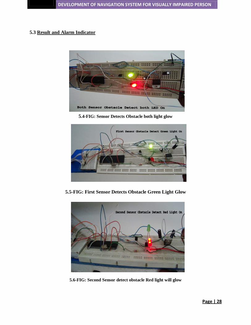
5.3 Result and Alarm Indicator
5.4-FIG: Sensor Detects Obstacle both light glow
5.5-FIG: First Sensor Detects Obstacle Green Light Glow
5.6-FIG: Second Sensor detect obstacle Red light will glow
DEVELOPMENT OF NAVIGATION SYSTEM FOR VISUALLY IMPAIRED PERSON
Page | 29
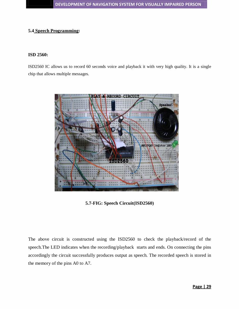
5.4 Speech Programming:
ISD 2560:
ISD2560 IC allows us to record 60 seconds voice and playback it with very high quality. It is a single
chip that allows multiple messages.
5.7-FIG: Speech Circuit(ISD2560)
The above circuit is constructed using the ISD2560 to check the playback/record of the
speech.The LED indicates when the recording/playback starts and ends. On connecting the pins
accordingly the circuit successfully produces output as speech. The recorded speech is stored in
the memory of the pins A0 to A7.

DEVELOPMENT OF NAVIGATION SYSTEM FOR VISUALLY IMPAIRED PERSON
Page | 30
1.4-TABLE: PINS USED TO GENERATE SPEECH
Address Mode (A0-A9)
The address inputs have two functions depending on the
level of the two most significant bits (MSB) of the address
pins, A8 and A9. When either or both the address pins are
LOW the inputs are all considered as address bits and are
used as start address for the current record.
Vssa, Vssd(A12, A13) These pins should be connected separately to the ground
through a low impedence path (capacitor)
SP+/SP-(A14, A15) An 8ohm speaker is connected to the address pins for
speech output
Vcca, Vccd (A16, A28) These pins are for the supply voltage
MIC(A17) The pin transfers the input signal and stores it in its
memory.
MIC REF (A18) This provides a noise cancelling reduction or common-
mode rejection input to the device.
AGC(A19) This is Automatic Gain Control. This s used for gain
controlling to compensate for the wide range of mirophone
levels.it allows sound to be recorded with minimal
distortion.
ANA IN (A20) The analog input transfers analog signal to the chip for
recording.
ANA OUT (A21) The analog output transfers the output to the speaker
CE(A23) This chip enable input is given LOW to enable record and
playback operations.
PD(A24) This pin is pulled to HIGH when neither record or
playback is operating. This pin is brought to HIGH to
reset the address pointer back to the beginning of the
memory array.
EOM(A25) This End of Message pin provides an active HIGH signal
indicating recording. This signal drives an LED for visual
indicator of the recording operation inprocess.
XCLK(A26) This pin is grounded.
P/R(A27) This playback/record starts when CE pin is low. A HIGH
DEVELOPMENT OF NAVIGATION SYSTEM FOR VISUALLY IMPAIRED PERSON
Page | 31
signal refers to playback while a LOW signal refers to
record.
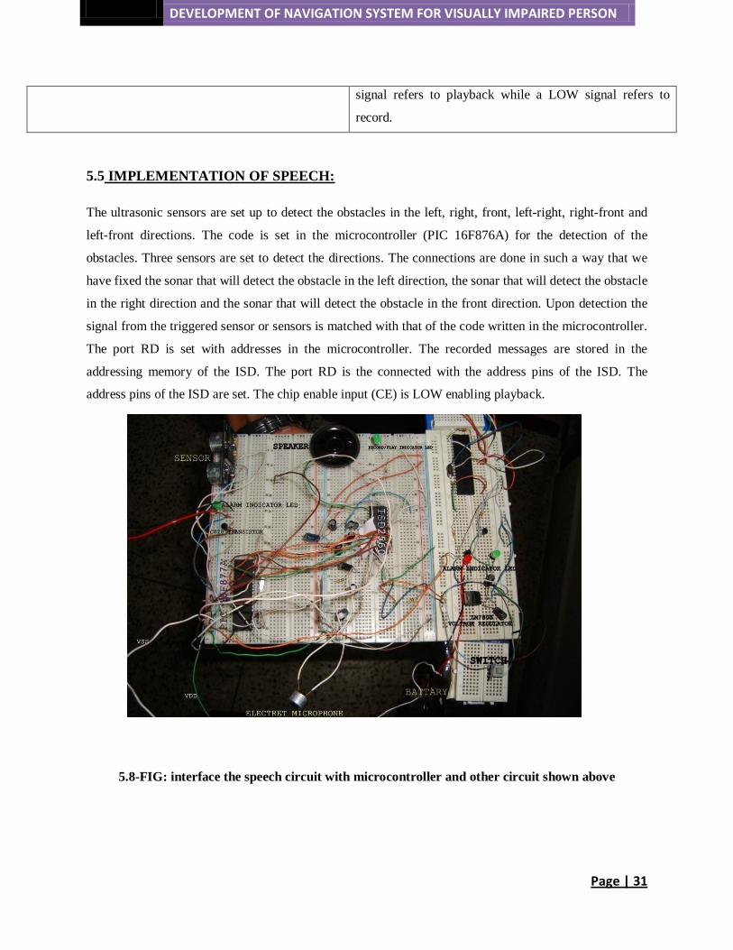
5.5 IMPLEMENTATION OF SPEECH:
The ultrasonic sensors are set up to detect the obstacles in the left, right, front, left-right, right-front and
left-front directions. The code is set in the microcontroller (PIC 16F876A) for the detection of the
obstacles. Three sensors are set to detect the directions. The connections are done in such a way that we
have fixed the sonar that will detect the obstacle in the left direction, the sonar that will detect the obstacle
in the right direction and the sonar that will detect the obstacle in the front direction. Upon detection the
signal from the triggered sensor or sensors is matched with that of the code written in the microcontroller.
The port RD is set with addresses in the microcontroller. The recorded messages are stored in the
addressing memory of the ISD. The port RD is the connected with the address pins of the ISD. The
address pins of the ISD are set. The chip enable input (CE) is LOW enabling playback.
5.8-FIG: interface the speech circuit with microcontroller and other circuit shown above

DEVELOPMENT OF NAVIGATION SYSTEM FOR VISUALLY IMPAIRED PERSON
Page | 32
Record:
According to the code set in the micro controller, on setting the CE pin to LOW, the PR pin to low the
recording cycle begins. For this the address pins provide the address cycle and the recording continues
until the PD pin is HIGH. On ending the record, the EOM is set to low. For visual interpretation this
signal drives an LED. When the LED lights up this means the recording is in progress and the when it
turns off this means the recording has ended. In such a manner three messages are recorded in the ISD,
“BAME BADHA”, “SHAMNE BADHA” and “DANE BADHA”.
Playback:
When obstacles are detected, the voice alert is triggered. The signal enters the conditional loop of the
microcontroller code. On matching with the certain code such as “BAME BADHA”, the CE pin is set to
low, the PR pin sets to high thus starting playback. During playback the LED will light up which is visual
indictor of EOM. The playback will continue until PD pin is high.
5.9-FIG: Overall Circuit Diagram between Sensor, Speech, Microcontroller, and Motor

DEVELOPMENT OF NAVIGATION SYSTEM FOR VISUALLY IMPAIRED PERSON
Page | 33
5.6 Result and Output Wave Shape of the Speech
5.10- FIG: Wave Shape When Detects in Obstacle Left (Say’ BAME BADHA’)
5.11- FIG: Wave Shape When Detects Obstacle in Right (Say’DANE BADHA’)
DEVELOPMENT OF NAVIGATION SYSTEM FOR VISUALLY IMPAIRED PERSON
Page | 34
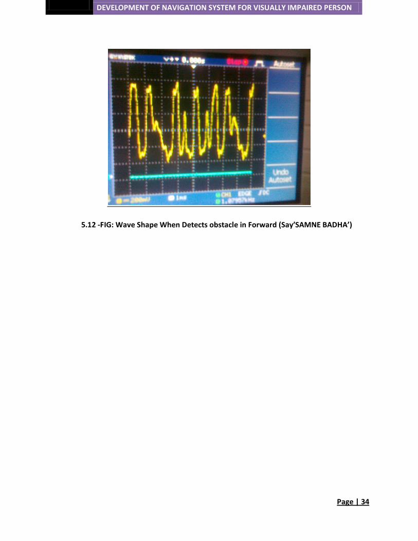
5.12 -FIG: Wave Shape When Detects obstacle in Forward (Say’SAMNE BADHA’)

DEVELOPMENT OF NAVIGATION SYSTEM FOR VISUALLY IMPAIRED PERSON
Page | 35
CHAPTER-6
6.1 SCOPE FOR IMPROVEMENT:
However while doing the experiment there are some things that can be improved further.
There is scope of improvement to our navigation system.
• During a windy day the sensors have difficulty in detecting obstacles. More powerful sensors can
be incorporated in the project to provide the detection of obstacles in a wider range. A motion
sound sensor can be further installed to maneuver around holes and bumps in the road.
• The position of the person can be known by GPS (Global Position System) which can also be
installed in the project. This will help the person to locate his position. T
• There is improvement of battery life-time; we used 9V battery as power source which can give
only 2 days backup. We can replace it by Lithium Battery to more effiecient
6.2 AN OUTLINE OF FUTURE WORK
Radio frequency identification (RFID):
Radio frequency identification (RFID) is a generic term that is used to describe a system that transmits the
identity (in the form of a unique serial number) of an object or person wirelessly, using radio waves.
RFID technology does not require contact or line of sight for communication. RFID data can be read
through the human body, clothing and non-metallic materials.
Components
A basic RFID system consists of three components:
• An antenna or coil
• A transceiver (with decoder)
• A transponder (RF tag) electronically programmed with unique information

DEVELOPMENT OF NAVIGATION SYSTEM FOR VISUALLY IMPAIRED PERSON
Page | 36
6.1-FIG: RFID SYSTEM
• The antenna emits radio signals to activate the tag and to read and write data to it.
• The reader emits radio waves in ranges of anywhere from one inch to 100 feet or more,
depending upon its power output and the radio frequency used. When an RFID tag passes through
the electromagnetic zone, it detects the reader's activation signal.
• The reader decodes the data encoded in the tag's integrated circuit (silicon chip) and the data is
passed to the host computer for processing.
The purpose of an RFID system is to enable data to be transmitted by a portable device, called a tag,
which is read by an RFID reader and processed according to the needs of a particular application. The
data transmitted by the tag may provide identification or location information, or specifics about the
product tagged, such as price, color, date of purchase, etc.
The Global Positioning System (GPS):
For future development, and as it is difficult to know where the blind is globally, it is then desirable to use
the global positioning system (GPS) in order to get the user position information.
6.2-FIG: Global Position System

DEVELOPMENT OF NAVIGATION SYSTEM FOR VISUALLY IMPAIRED PERSON
Page | 37
CONCLUSION
We presented a navigation aid which helps blind people to navigate safely. This aid allows the blind
person to avoid obstacles by warning system through vibrations and voice. Our main goal is to make a
system that will be cost effective and easier for the physically challenged person to handle. In order to
make it easier for the person to use, we have fixed the sonar’s for detecting obstacles in particular
direction. Therefore the person does not require to move the cane around to detect barriers like they do
with the normal cane. They can easily walk with the cane and the sonar’s will simply detect the problems
and help the person to maneuver around it. We hope that this aid will be an effective, low-cost solution
for reducing navigation problems for blind users.

DEVELOPMENT OF NAVEGATION SYSTEM FOR VISUAL IMPAIR PERSON
Page | 38
Appendix
Code for Obstacle Detection, Alarm System and Speech Output
-A.
// LCD module connections sbit LCD_RS at RB4_bit; sbit LCD_EN at RB5_bit; sbit LCD_D4 at RB0_bit; sbit LCD_D5 at RB1_bit; sbit LCD_D6 at RB2_bit; sbit LCD_D7 at RB3_bit; sbit LCD_RS_Direction at TRISB4_bit; sbit LCD_EN_Direction at TRISB5_bit; sbit LCD_D4_Direction at TRISB0_bit; sbit LCD_D5_Direction at TRISB1_bit; sbit LCD_D6_Direction at TRISB2_bit; sbit LCD_D7_Direction at TRISB3_bit; // End LCD module connections #define SIG_PIN RB7_bit #define SIG_TRIS TRISB7_bit #define LED_PIN RA0_bit #define LED_TRIS TRISA0_bit #define CE_PIN RA1_bit #define CE_TRIS TRISA1_bit #define SAMNE_BADHA RA3_bit #define SAMNE_TRIS TRISA3_bit #define BAME_BADHA RA4_bit #define BAME_TRIS TRISA4_bit void main() { unsigned int EchoTime = 0, i; float Distance, Distance2 = 0; char txt[20]; char DANE_BADHA=0 ; PWM1_Init(40000); PWM1_set_duty(0); PWM1_Start(); ADCON1 = 6;
DEVELOPMENT OF NAVEGATION SYSTEM FOR VISUAL IMPAIR PERSON
Page | 39
Lcd_Init(); Lcd_Cmd(_LCD_CLEAR); // Clear display Lcd_Cmd(_LCD_CURSOR_OFF); // Cursor off Delay_us(5); LED_PIN = 0; LED_TRIS = 0; CE_TRIS = 1; CE_PIN = 1; LCD_Out(1, 1, "Dist: "); LCD_Out(3, 1, "Dist: "); Delay_ms(500); while(1) { /* * SONAR 1 */ // make IO as output SIG_PIN = 0; SIG_TRIS = 0; Delay_us(5); // give the start signal SIG_PIN = 1; Delay_us(5); SIG_PIN = 0; // wait.. Delay_us(200); // make IO as input SIG_TRIS = 1; EchoTime = 0; while(SIG_PIN == 1) { EchoTime++; Delay_us(10); } Distance = EchoTime / 5;
DEVELOPMENT OF NAVEGATION SYSTEM FOR VISUAL IMPAIR PERSON
Page | 40
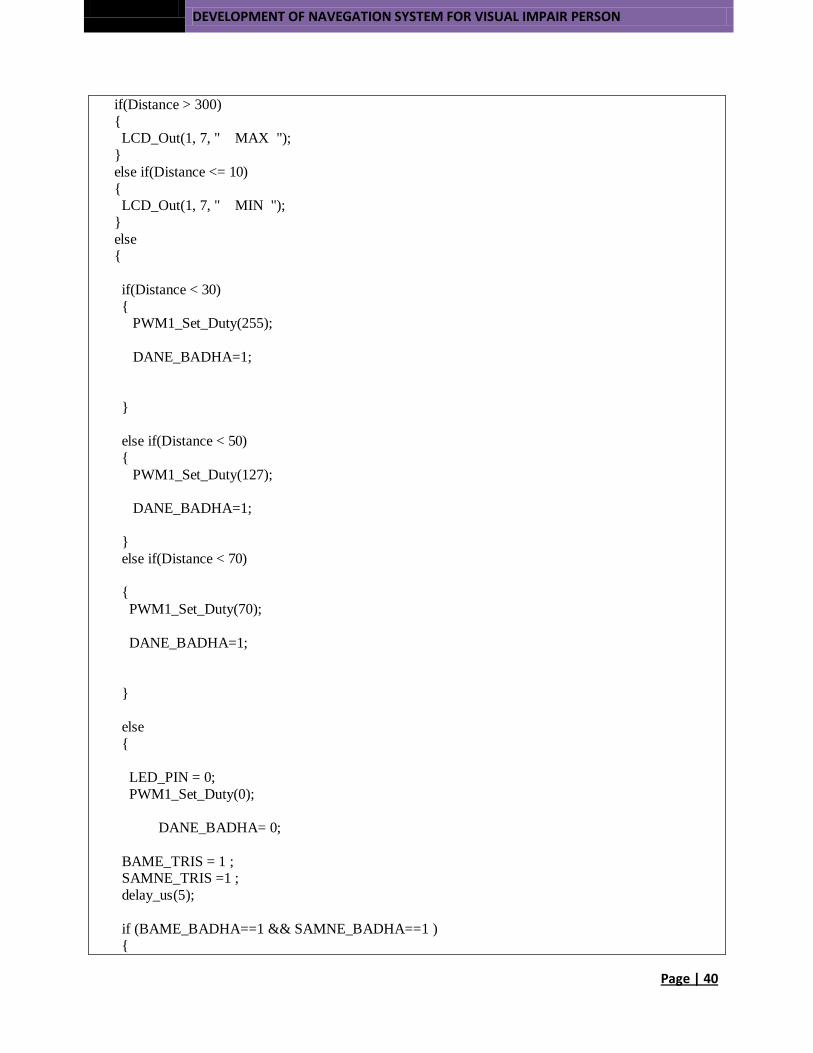
if(Distance > 300) { LCD_Out(1, 7, " MAX "); } else if(Distance <= 10) { LCD_Out(1, 7, " MIN "); } else { if(Distance < 30) { PWM1_Set_Duty(255); DANE_BADHA=1; } else if(Distance < 50) { PWM1_Set_Duty(127); DANE_BADHA=1; } else if(Distance < 70) { PWM1_Set_Duty(70); DANE_BADHA=1; } else { LED_PIN = 0; PWM1_Set_Duty(0); DANE_BADHA= 0; BAME_TRIS = 1 ; SAMNE_TRIS =1 ; delay_us(5); if (BAME_BADHA==1 && SAMNE_BADHA==1 ) {

DEVELOPMENT OF NAVEGATION SYSTEM FOR VISUAL IMPAIR PERSON
Page | 41
LED_PIN = 1; Delay_us(5); LED_PIN = 0; TRISD = 0; PORTD = 150; Delay_us(200); CE_PIN= 0; CE_TRIS = 0 ; Delay_us(200); CE_TRIS = 1 ; } else if (DANE_BADHA ==1 && BAME_BADHA==1) { LED_PIN = 1; Delay_us(5); LED_PIN = 0; TRISD = 0; PORTD = 250; Delay_us(200); CE_PIN= 0; CE_TRIS = 0 ; Delay_us(200); CE_TRIS = 1 ; } else if (DANE_BADHA == 1 && SAMNE_BADHA==1) { LED_PIN = 1; Delay_us(5); LED_PIN = 0; TRISD = 0; PORTD = 200; Delay_us(200); CE_PIN= 0 ; CE_TRIS = 0 ; Delay_us(200); CE_TRIS = 1 ; } else if (DANE_BADHA== 1) { LED_PIN = 1; Delay_us(5); LED_PIN = 0; TRISD = 0;
DEVELOPMENT OF NAVEGATION SYSTEM FOR VISUAL IMPAIR PERSON
Page | 42
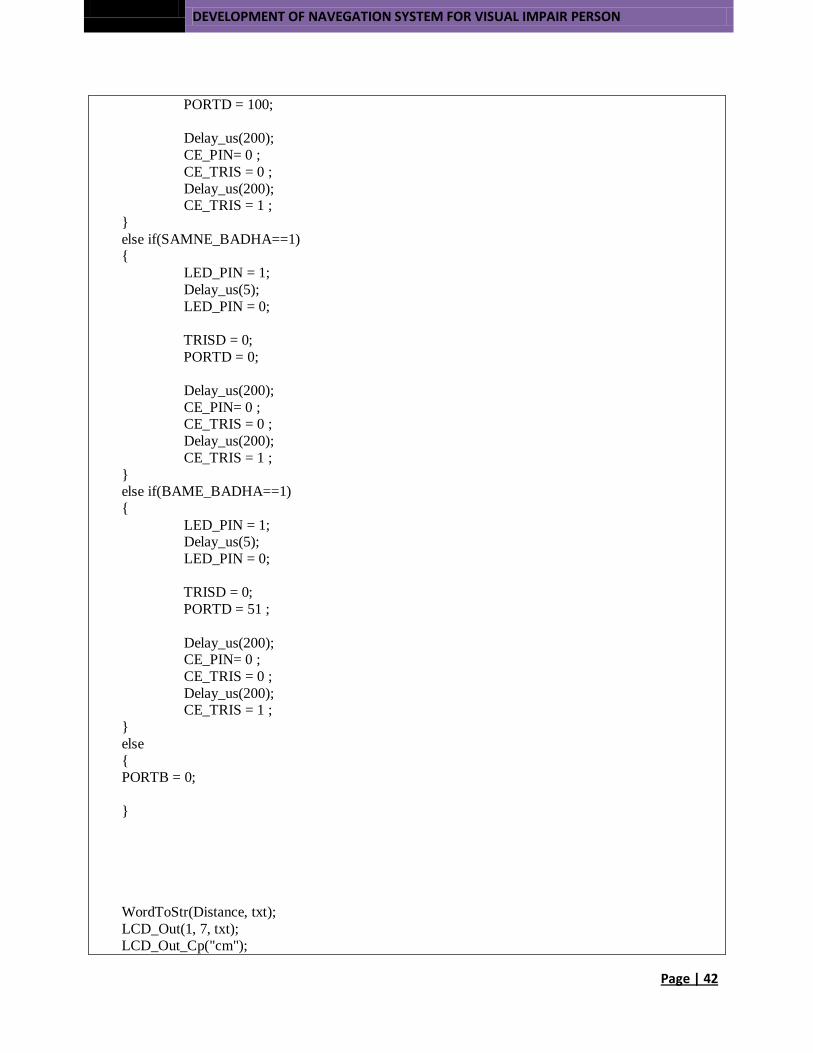
PORTD = 100; Delay_us(200); CE_PIN= 0 ; CE_TRIS = 0 ; Delay_us(200); CE_TRIS = 1 ; } else if(SAMNE_BADHA==1) { LED_PIN = 1; Delay_us(5); LED_PIN = 0; TRISD = 0; PORTD = 0; Delay_us(200); CE_PIN= 0 ; CE_TRIS = 0 ; Delay_us(200); CE_TRIS = 1 ; } else if(BAME_BADHA==1) { LED_PIN = 1; Delay_us(5); LED_PIN = 0; TRISD = 0; PORTD = 51 ; Delay_us(200); CE_PIN= 0 ; CE_TRIS = 0 ; Delay_us(200); CE_TRIS = 1 ; } else { PORTB = 0; } WordToStr(Distance, txt); LCD_Out(1, 7, txt); LCD_Out_Cp("cm");

DEVELOPMENT OF NAVEGATION SYSTEM FOR VISUAL IMPAIR PERSON
Page | 43
} Delay_ms(1); } }
DEVELOPMENT OF NAVEGATION SYSTEM FOR VISUAL IMPAIR PERSON
Page | 44
Appendix
-B
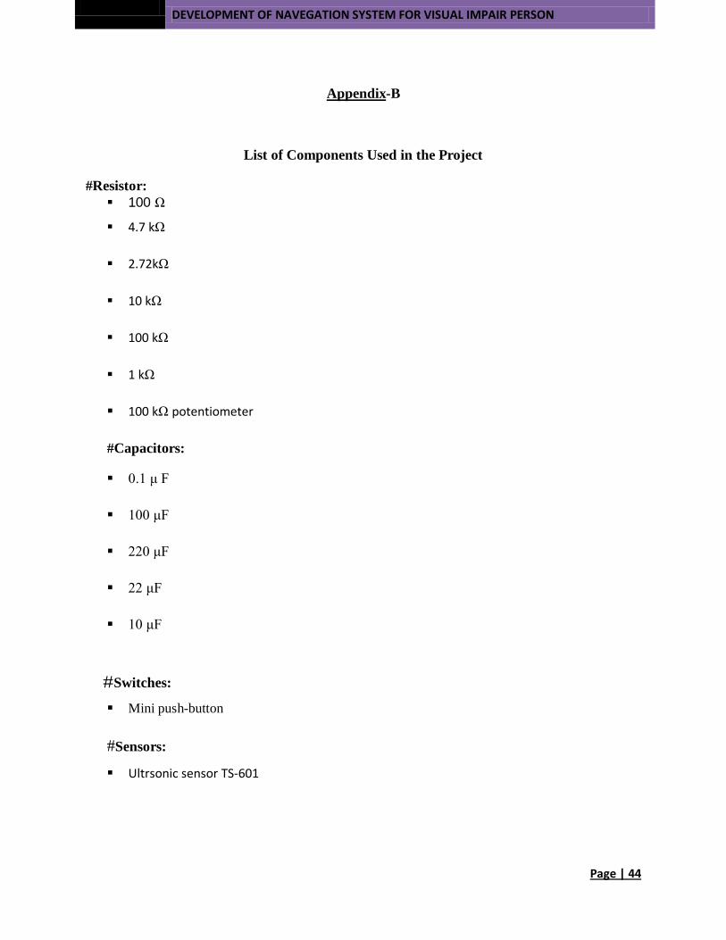
List of Components Used in the Project
#Resistor: 100 Ω
4.7 kΩ
2.72kΩ
10 kΩ
100 kΩ
1 kΩ
100 kΩ potentiometer
#Capacitors:
0.1 μ F
100 μF
220 μF
22 μF
10 μF
#Switches: Mini push-button
#Sensors: Ultrsonic sensor TS-601

DEVELOPMENT OF NAVEGATION SYSTEM FOR VISUAL IMPAIR PERSON
Page | 45
#Discrete Semiconductor
C828 PNP transistor
#Integrated Circuit:
PIC16F877A Microcontroller
ISD2560 Single Chip Record and Playback
LM7805 Voltage Regulator
Motor(Cell Phone Vibrator)
#Miscellaneous:
20MHz Crystal
LCD Display
Speaker (8 ohm)
Electret Microphone
Breadboard
Connection Cord
Mini Trainer Board
9 volt battery

DEVELOPMENT OF NAVEGATION SYSTEM FOR VISUAL IMPAIR PERSON
Page | 46
Reference
• •
http://www.prowave.com
• MuRata Corp. application notes: http://www.murata.com
• MicroChip Technology Inc. application notes:
• http://www.microchip.com
• MicroChip Forum:
• http://forum.microchip.com/
• MELabs PICBASIC Forums:
• Basic Micro Forums:
• http://forums.basicmicro.net/Default.aspx Proton PIC
• http://www.picbasic.org/forum/
• mikroElektronika Forum:
• http://www.mikroe.com/forum/search.php?mode=results
• EDABoard:
•
http://www.edaboard.com
www.massey.ac.nz/~wlxu/mechatronics2008/.../report.doc
•
•
www.icadi.icta.ufl.edu/projects/publications/wearableConf.pd
•
www2.glos.ac.uk/gdn/disabil/blind/blind.pdf
http://www.researchgate.net/publication/220795466_VI-Navi_a_novel_indoor_navigation_system_for_visually_impaired_people
•
•
www.ieeexplore.ieee.org/xpl/articleDetails.jsp;jsessionid..
www.kst.tugab.bg/staff/rosen/10.pdf
• www.ijettjournal.org/volume-3/issue-2/IJETT-V3I2P217.pdf
• http://www.tradezz.com/buy_503296_Ultrasonic-Sensor-TS601.htm
• http://mdubuc.freeshell.org/Robotics/Tips.html
• http://www.best-microcontroller-projects.com/pic-micro.html
• http://www.datasheets.com/search/index.jsp?KW=ggl_ds&gclid=CK3Qzq7WmrQCFYl66wodlGkAag
• www.datasheetcatalog.com
• ww1.microchip.com/downloads/en/devicedoc/39582b.pdf

DEVELOPMENT OF NAVEGATION SYSTEM FOR VISUAL IMPAIR PERSON
Page | 47
• www.biltek.tubitak.gov.tr/gelisim/elektronik/.../ISD2560.pdf
• http://citeseerx.ist.psu.edu/viewdoc/summary?doi=10.1.1.19.8438
• http://ece-projects.blogspot.com/2011/05/speed-control-of-dc-motor-using-micro.html
• https://instruct1.cit.cornell.edu/courses/ee476/FinalProjects/s2007/jjl49_mar97/jjl49_mar97/index.htm
• http://www.micro-examples.com/public/microex-navig/doc/090-ultrasonic-ranger.html
• http://www.arduino.cc/en/Tutorial/PWM
•
http://electronics-diy.com/electronic_schematic.php?id=570

DEVELOPMENT OF NAVEGATION SYSTEM FOR VISUAL IMPAIR PERSON
Page | 48
THE END