Embed Size (px)
Citation preview
DEVELOPMENT OF CUTTER FOR PRINTED CIRCUIT BOARD USING
HYDRAULIC PRINCIPLE
MOHD MUHAYMIN ISMAIL
A report submitted in partial fulfilment of the
requirements for the award of the degree of
Bachelor of Mechanical Engineering
Faculty Mechanical Engineering
Umversiti Malaysia Pahang
NOVEMBER 2007
7
ABSTRACT
Cutter was known since long times ago as something that was use to cut the
thing into smaller piece. Starting from the usual rock at the rock age till the high
technology cutter which was make from the precious and valuable material like
diamond at this modern age, the cutter was develop to make our daily life more
easier and easier. This project is proposed to design and fabricate a cutter as benefit
to cut the printed circuit board, the board which contains cuprum as a trace to
connect the electricity current to the electronic component like resistors and
capacitors. The printed circuit board was widely used in modern electronic and
electric component like radio and computer because it can minimize the space and
reduce the manufacturing cost by assemble all electronic components together. The
usual way to cut the printed circuit board is by using hand because the sensitive of it.
By develop the cutter it will make the way to cut the printed circuit board is more
efficient without give the damage to the board. In this project, the main purpose of
study is to develop the cutter to make sure the cutter can achieve it objective.
Developments of cutter are starting by choosing the right cutter's material then
design and finally fabricate the cutter.
V

ABSTRAK
Pemotong telah dikenali sejak dahulu sebagai alat untuk memotong sesuatu
benda kepada kepingan yang lebih kedil. Bermula dengan penggunaan batu biasa di
zaman batu hinggalah pemotong bertekno!ogi tinggi yang diperbuat daripada bahan
bernilai dan berharga seperti berlian path zaman moden mi, pemotong telah direka
untuk memudahkan urusan harian kita. Projek mi bertujuan mereka dan membentuk
pemotong untuk papan litar bersepadu yang mengandungi kupruni sebagai trek untuk
mengalir arus eletrik kepada peralatan elekronik seperti kapasitor dan penntang.
Papan litar bersepadu telah digunakan secara meluas dalam peralatan elektrik moden
seperti komputer dan radio kerana ia dapat menjimat ruang dan mengurangkan kos
pembuatan dengan menyatukan semua peralatan elektrik. Cara biasa memotong
papan litar bersepadu adalah dengan menggunakan tangan kerana litar im sensitif.
The pembentukan pemotong mi ia dapat memotong papan litar bersepadu dengan
lebih efisien tanpa merosakkan litar tersebut. Dalam projek mi, pengajian utama
adalah merekabentuk pemotong untuk memastikkan ia mencapai objektithya. Kerja
merekabentuk bermula dengan pemilihan pemotong yang dikehendaki kemudian
mereka dan diakhiri dengan membentuk pemotong tersebut.
vi

TABLE OF CONTENTS
CHAPTER
TITLE PAGE
STUDENT DECLARATION
DEDICATION
ACKNOWLEDGEMENT iv
ABSTRACT v
TABLE OF CONTENTS vii
LIST OF TABLES x
LIST OF FIGURES xi
1
INTRODUCTION I
1.1 Project Background i
1.2 Project Objective 2
1.3 Scope of Project 2
1.4 Problem Statement 2
2 LITERATURE REVIEW 3
2.1 Printed Circuit Board 3
2. 1.1 Component of PCB 5
2.2 Laminated of PCB 6
2.2.1 Epoxy 7
2.2.2 FR-4 10
2.2.3 FR-2 9
2.2.4 Polytetrafluoroethylene 10

VII'
4
2.2.5 Polymide 11
2.3 Hydraulic 12
2.3.1 Hydraulic Cylinder 13
2.3.2 Hydraulic Liquids 16
2.4 SolidWorks 17
2.5 Cutting Tools 18
2.5.1 Carbides 19
2.5.2 High Speed Steel 20
2.5.3 Carbon and Medium Alloys 20
METHODOLOGY 22
3.1 Introduction 22
3.2 Literature review 25
3.3 Design 25
3.4 Analysis 28
3.5 Fabricate 28
3.5.1 Milling Process 28
3.5.2 Drilling 29
3.5.2.1 Taps 31
3.5.2.2 Material Removal Rate 34
3.5.3 Grinding 35
3.6 Assemble 36
RESULT 38
4.1 Introduction 38
4.2 Result 38
4.3 Discussion 39
5
CONCLUSION 42
5.1 Conclusions 42

lx
REFERENCES
48
APPENDIX A 45

LIST OF TABLES
TABLE NO. TITLE PAGE
2.1 Life time of PCB board 6 2.2 FR-4 Properties 9 2.3 FR-2 Properties 10 2.4 Properties of Polyimide 11 2.5 Differential between hydraulic and pneumatic 13 2.6 Hydraulic cylinder specification 16 3.1 Recommendations for Speed and Feed in Drilling 32
x
LIST OF FIGURES
FIGURE NO. TITLE PAGE
2.1 Printed Circuit Board 3 2.2 Epoxy on PCB board 8 2.3 Hydraulic Cylinder 14 3.1 Overall Process Flow Chart 23 3.2 Flow Chart for Assembly Process 24 3.3 Design A 26 3.4 Design B 26 3.5 Design C 27 3.6 Cylinder Isometric View 27 3.7 Aluminium Isometric View 27 3.8 Horizontal Milling Machine 30 3.9 Drill Machine 31 3.10 Grinding Machine 35 3.11 Hand Grinder 36 3.12 Aluminium after Assembled 37 3.13 Side View 37 4.1 During Cutting Process 41 4.2 After Cutting Process 41
xl

CHAPTER 1
IITRODUCTION
Li Project Background
Printed Circuit Board (PCB) is main component is electronic device like
computer, television and handset. The function of this board is to hold and support
the component like capacitor and to connect the electronic component using
conductive paths ways or trace. After the manufacturing of the board is finish and
complete, it usually came in large size and all the board is attach to each other. So, to
put in it in the device, the large board needs to cut to become small one. The process
to cut the PCBs is usually using hand or scissor. This is because the PCB is sensitive
and easy to damage. But this process is slow and using more workers. So the new
ways are develop to find the effective ways to cut the board.
In this project the cutter will be develop using the best material. Before
fabricate it, the design must be choose to make sure the cutter is suitable to cut the
board. The meaning of design and develop here is to design the machine using
engineering drawing software like Solidwork then fabricate it to make this machine
work. Printed circuit board is the board that consist of layer of fiberglass and carbon.
It usually use in electronic device to make sure the electricity work perfectly and to
minimize the space because many electrical components can be assembles on it.
While hydraulic is science that dealing with the mechanical properties of liquid. It
works like pneumatic but hydraulic use liquid while pneumatic use air as a medium.

tj
1.2 Project Objective
The main propose for this project is to develop and design the cutter for
printed circuit board (PCB) using hydraulic principle that can be used for to cut the
PCB.
1.3 Scope of Project
The scope for this project:
i. Using Solidwork software to made 3D model
ii. Check the failure analysis
iii. Fabricate and assemble all part for this project
1.4 Problem Statement
In manufacturing industries, cost and time are important factor to make the
profit. We must set the time correctly if we want to gain the higher profit. Some of
this wasting time is depend on what the type of machine that we use. Some machines
are work slowly, not accurate and hardly to maintenance while the other type are
faster, accurate and easy to maintenance. Machines that work faster and accurate are
usually high price and slower machine is lower price. So choosing the right machine
is hard because we have to choose the machines that suitable for our budget and our productivity. Using slower machines can slower productivity but if we use faster
machine we have to think of the price of it. So to settle this problem have to develop
new type of machine that is faster but the price of is suitable for industries use.
CHAPTER 2
LITERATURE REVIEW
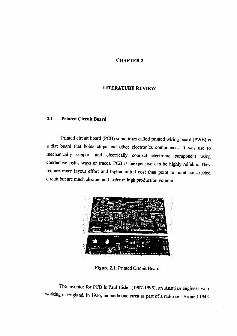
2.1 Printed Circuit Board
Printed circuit board (PCB) sometimes called printed wiring board (PWB) is
a flat board that holds chips and other electronics components. It was use to
mechanically support and electrically connect electronic component using
conductive paths ways or traces. PCB is inexpensive can be highly reliable. They
require more layout effort and higher initial cost than point to point constructed
circuit but are much cheaper and faster in high production volume.
Figure 2.1: Printed Circuit Board
The inventor for PCB is Paul Eisler (1907-1995), an Austrian engineer who
working in England. In 1936, he made one circa as part of a radio set. Around 1943

4
when the War World II occurs, United State of America (USA) began to use the
technology on large scale to make radio for army use. After the war, in 1948, USA
released the invention for commercial use. Printed circuit board not becomes popular
in consumer electronic until middle 1950s, after the Auto-Assembly process was
developed by the United State Army. Before printed circuit was develop, point-to-
point construction was used but for prototype and small production runs, wire wrap
can be more efficient.
There are many good reasons for using printed circuit board instead of other
interconnection wiring methods and component mounting technique:
i. The size of component assembly is reduced with corresponding
decrease in weight.
ii. Quantity production can be achieved at lower unit cost
iii. Component wiring and assembly can be mechanized
iv. Circuit characteristic can be maintained without introducing variation
in inter-circuit capacitance
V. They ensure a high level of repeatability and offer uniformity of
electrical characteristics from assembly to assembly.
vi. The location of part is fixed, which simplifies identification and
maintenance of electronic equipment and systems.
vii. Printed circuit board wiring personnel require minimal technical skills
and training. Changes of miswiring of circuited wiring are minimized.
Most PCBs are composed of between one and twenty-four conductive layers
separated and supported by layers of insulating material (substrates) laminated (glued
with heat, pressure & sometimes vacuum) together. Layers may connect together
through drilled holes called vias. To form an electrical connection, the small rivets
are inserted into the holes. Even though they may not form electrical connection to
all layers, these holes are typically drilled completely though the PC board.
5
There is no standard thickness for printed circuit board. The limiting factor
for printed circuit board thickness is the diameter of the smallest hole, especially
when the holes are plated though..
The final board thickness will depend upon the number of conductor layers
and on the electrical layer-to-layer spacing requirements of the design. In multi-layer
boards the increase in cost is not directly proportional to the increase in the number
of conductive layers. For example, doubling the number of layers from four to eight
will probably increase cost by only 30 per cent. However, if the number of conductor
layer exceeds 10, the extra layer cost increase at a rapid rate.
The lower temperature to make sure PC board can be use is -55° C and
maximum temperature is 125° C. Nowadays; PC board is widely used in electronic
device like computer, aircraft and satellite. The life time of PC board is depending on
which industries it was use. For example for computer, PC board can give it service
for 5 years. For more detail about PC board life time, see Table 2.1
2.1.1 Component of a Printed Circuit Board
The essential components of a printed circuit board are:
i. the base, which is a thin board of insulating material, rigid or flexible which
support all conductor and component
ii. the conductor, normally of high purity copper in the form of thin strips of
appropriate shapes firmly attached to base material
The base provides mechanical support to all copper areas and all components
attached to the copper. The electrical properties of the completed circuit depend upon
the dielectric properties of the base material and must therefore, be known and
appropriately controlled
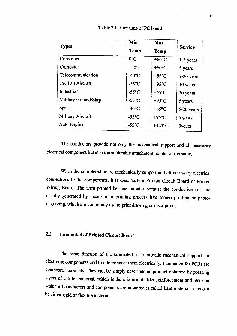
Table 2.1: Life time of PC board
TypesMin
Temp
Max
TempService
Consumer 0°C +60°C 1-3 years
Computer +150C ±60°C 5 years
Telecommunication 40°C ±85°C 7-20 years
Civilian Aircraft -55°C +95°C 10 years Industrial -55°C +55°C 10 years
Military Ground/Ship -55°C +95°C 5 years Space -40°C +85°C 5-20 years Military Aircraft -55°C +95°C 5 years Auto Engine -55°C +125°C Syears
The conductors provide not only the mechanical support and all necessary
electrical component but also the solderable attachment points for the same.
When the completed board mechanically support and all necessary electrical
connections to the components, it is essentially a Printed Circuit Board or Printed
Wiring Board. The term printed became popular because the conductive area are
usually generated by means of a printing process like screen printing or photo-
engraving, which are commonly use to print drawing or inscriptions.
2,2 Laminated of Printed Circuit Board
The basic function of the laminated is to provide mechanical support for
electronic components and to interconnect them electrically. Laminated for PCBs are
composite materials. They can be simply described as product obtained by pressing
layers of a filler material, which is the mixture of filler reinforcement and resin on
which all conductors and components are mounted is called base material. This can
be either rigid or flexible material.

7
2.2.1 Epoxy
Epoxy is polyepoxide is a thermosetting epoxide polymer that cures when
mixed with a catalyzing agent or hardener. Most common epoxy resins are produced
from a reaction between epichiorohydrin (reactive organic compound) and
bisphenol-A (a chemical compound with two phenol functional groups in its
molecule that belongs to the phenol class of aromatic organic compounds. It is
prepared by reaction of two equivalents of phenol with one equivalent of acetone). It
was produced in 1927 in United State of America. While the first synthesis of
bisphenol-A based epoxy resin is produced by Dr. Pierre Castan who works with
Ciba, Ltd. Of Switzerland. Because of that Ciba Company became one of three major
epoxy resin producers worldwide.
Epoxies will not stick to mold-release compound recommended for use with
epoxy and polyethylene sheeting, like disposable paints tarps and sandwich bags.
Epoxy does not stick to the shiny side of packaging tape or paraffin wax.
The applications for epoxy based materials are extensive and include
coatings, adhesives and composite materials such as those using carbon fiber and
fiberglass reinforcements, although polyester, vinyl ester, and other thermosetting
resins are also used for glass-reinforced plastic. The chemistry of epoxies and the
range of commercially available variations allow cure polymers to be produced with
a very broad range of properties. In general, epoxies are known for their excellent
adhesion, chemical and heat resistance, good to excellent mechanical properties and
very good electrical insulating properties, but almost any property can be modified
for example silver-filled epoxies with good electrical conductivity are available,
although epoxies are typically electrically insulating.
Epoxy resin formulations are also important in the electronics industry, and
are employed in motors, generators, transformers, switchgear, bushings, and
insulators. Epoxy resins are excellent electrical insulators and protect electrical components from short circuiting, dust and moisture.

8
In the electronics industry, epoxy resins are the primary resin used in over
molding integrated circuits, transistors and hybrid circuits, and making printed circuit
boards. The largest volume type of circuit board is a sandwich of layers of glass cloth
bonded into a composite by an epoxy resin. Epoxy resins are used to bond copper
foil to circuit board substrates, and are a component of the solder mask on many
circuit boards.
Figure 2.2: Epoxy on PC board
2.2.2 FR-4
FR-4 or Flame Resistant 4 is a material that was used to make printed circuit
board. It described the board itself with no copper covering. The FR-4 that used to
make the PC board is usually Ultra Violet (UV) stabilized with a tetrafunctional resin
system. The FR-4 is typically is yellowish colour. FR-4 is manufactured as insulator
(without copper) is typically a difunctional resin system and a greenish colour.
A PCB needs to be an insulator to avoid shorting the circuit, physically strong
to protect the copper tracks placed upon it, and to have certain other physical
electrical qualities. FR-4 is preferred over cheaper alternatives due to several
mechanical and electrical properties,

ze
i. It is less lossy at high frequencies,
ii. Absorbs less moisture,
iii. Has greater strength and stiffness
iv. Highly flame resistant compared to its less costly counterpart
Besides being used for make PC board, FR-4 also being used for
manufacturing insulating or structural component.
2.2.3 FR-2
FR-2 is an abbreviation for Flame Resistant 2. It was used to manufacture the
printed circuit board. Its properties are similar to NEMA (National Electrical
Manufacturing Association-United Stated based Association) grade XXXP (MIL-P-
3115) material, and can be substituted for the latter in many applications.
Table 2.2: FR-4 properties
Property Value
Dielectric constant 4.70 Max, 4.35 @ 500 MHz, 4.34 @ 1 (Permittivity) GHz
Dissipation Factor (Loss
tangent) 0.02 @1 MHz, 0.01 @ 1 GHz
Dielectric strength 20 MV/rn (500 V/mi!)
Surface Resistivity (mm) 2x10"5 ML
Volume Resistivity (mm) 8x10"7 M)*cm
Typical Thickness 1.25 mm - 2.54 nun (0.049-0.100 inches) Typical stiffness (Young's
modulus) 17 GPa (2.5xl0"6 PSI; for use in PCBs) Density 1.91 kg/L
10
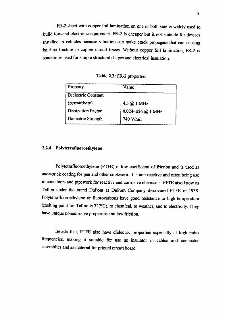
FR-2 sheet with copper foil lamination on one or both side is widely used to
build low-end electronic equipment. FR-2 is cheaper but it not suitable for devices
installed in vehicles because vibration can make crack propagate that can causing
hairline fracture in copper circuit traces, Without copper foil lamination, FR-2 is
sometimes used for simple structural shapes and electrical insulation.
Table 2.3: FR-2 properties
Property Value
Dielectric Constant
(permittivity) 4.5 1 MHz
Dissipation Factor 0.024-.026 @ 1 MHz
Dielectric Strength 740 V/mil
2.2.4 Polytetrafluoroethylene
Polytetrafluoroethylene (PTFE) is low coefficient of friction and is used as
anon-stick coating for pan and other cookware. It is non-reactive and often being use
in containers and pipework for reactive and corrosive chemicals. PFTE also know as
Teflon under the brand DuPont as DuPont Company discovered PTFE in 1938.
Polytetrafluoroethylene or fluorocarbons have good resistance to high temperature
(melting point for Teflon is 327C), to chemical, to weather, and to electricity. They
have unique nonadhesive properties and low friction.
Beside that, PTFE also have dielectric properties especially at high radio
frequencies, making it suitable for use as insulator in cables and connector
assemblies and as material for printed circuit board.
11
2.2.5 Polyimide
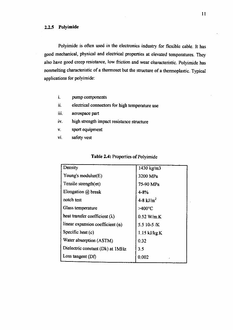
Polyimide is often used in the electronics industry for flexible cable. It has
good mechanical, physical and electrical properties at elevated temperatures. They
also have good creep resistance, low friction and wear characteristic. Polyimide has
nonmelting characteristic of a thermoset but the structure of a thermoplastic. Typical
applications for polyimide:
i. pump components
ii. electrical connectors for high temperature use
iii. aerospace part
iv. high strength impact resistance structure
V. sport equipment
vi. safety vest
Table 2.4: Properties of Polyimide
Density 1430 kg/m3
Young's modulus(E) 3200 MPa
Tensile strength(et) 75-90 MPa
Elongation @ break 4-8%
notch test 4-8 kJ/m2
Glass temperature >400°C
heat transfer coefficient (A') 0.52 W/m.K
linear expansion coefficient (a) 5.5 10-5 /K
Specific heat (c) 1.15 kJlkg.K
Water absorption (ASTM) 0.32
Dielectric constant (Dk) at 1MHz 3.5
Loss tangent (Df) 0.002
12
2.3 hydraulic
Hydraulic is a systems that dealing with liquid. Hydraulic system is same
with pneumatic system but hydraulic use liquid media such as oil while pneumatic
use gas or air. Although it work using same principle with pneumatic, hydraulic can
create large pressure than pneumatic system but pneumatic is cleaner than hydraulic.
Hydraulic system is always greasy. Other differential between hydraulic and
pneumatic system may be refer in Table 2.5
Hydraulic systems generally rely on pressure in a fluid. Pressure occurs is
fluid when it is subjected to a force. Increasing the force will increase the pressure in
direct proportion. Decreasing the area also will increase the pressure. Pressure in the
fluid can therefore be defined as the force acting per unit area, or;
A
where F = ma ; a acceleration
in mass
A = area
The SI system defines pressure as the force in Newton's per square meter
(Nm 2). The SI unit of pressure is the Pascal (with 1 Pa = 1 Nm 2 . One Pascal is very
low pressure for practical use, so the kilopascal (lkPa) or the megapascal (iMpa) is
commonly used. Pressure can also arise in a fluid from the weight of a fluid. This
usually known as the head pressure at the bottom of the fluid is directly proportional
to height h. the head pressure is given by:
where p = density
g = gravity
h height

13
Table 2.5: Differential between hydraulic and pneumatic system
Hydraulic Pneumatic
Energy
source Electric motor Electric motor or diesel driven
Energy
storage Limited (accumulator) Good (reservoir)
Distribution Good. Can be treated as aplant
system Limited basically a local facility wide service
Energy cost Medium Highest
Rotary Wide speed range control actuators Low speed. Good control difficult
Linear
actuator Cylinders. Very high force Cylinders. Medium force
Controllable
force Controllable high force Controllable medium force Points to Leakage dangerous and unsightly. Fire
note hazard Noise
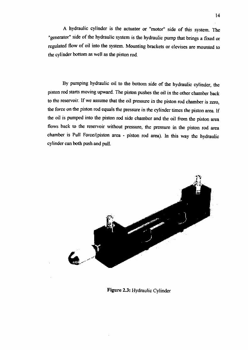
2.3.1 Hydraulic Cylinder
Hydraulic cylinders (also called linear hydraulic motors) are mechanical
actuators that are used to give a linear force through a linear stroke. Hydraulic
cylinders get their power from pressurized hydraulic fluid, which is typically oil. The
cylinder consists of a cylinder barrel, in which a piston connected to a piston rod is
moving. The barrel is closed by the cylinder bottom and by the cylinder head where
the piston rod comes out of the cylinder. The piston has sliding rings and seals. The
Piston divides the inside of the cylinder in two chambers, the bottom chamber and
the piston rod side chamber. The hydraulic pressure acts on the piston to do linear work.
14
A hydraulic cylinder is the actuator or "motor" side of this system. The
"generator" side of the hydraulic system is the hydraulic pump that brings a fixed or
regulated flow of oil into the System. Mounting brackets or devises are mounted to
the cylinder bottom as well as the piston rod.
By pumping hydraulic oil to the bottom side of the hydraulic cylinder, the
piston rod starts moving upward. The piston pushes the oil in the other chamber back
to the reservoir. If we assume that the oil pressure in the piston rod chamber is zero,
the force on the piston rod equals the pressure in the cylinder times the piston area. If
the oil is pumped into the piston rod side chamber and the oil from the piston area
flows back to the reservoir without pressure, the pressure in the piston rod area
chamber is Pull Force/(piston area - piston rod area). In this way the hydraulic
cylinder can both push and pull.
Figure 2.3: Hydraulic Cylinder

15
A hydraulic cylinder consists out of following parts:
i. Cylinder barrel
ii. Cylinder bottom
iii. Cylinder head
iv. Piston
v. Cylinder bottom connection
vi. Piston rod connection
vii. Feet for mounting of the barrel
The cylinder barrel is mostly a seamless thick walled forged pipe that must be
machined internally. The cylinder barrel is ground and/or honed internally. In most
hydraulic cylinders, the barrel and the bottom are welded together. This can damage
the inside of the barrel. Therefore it is better to have a screwed or flanged connection.
In that case also the barrel pipe can be maintained and/or repaired in future. The
cylinder head is sometimes connected to the barrel with a sort of a simple lock (for
simple cylinders). In general however the connection is screwed or flanged. Flange
connections are the best, but also the most expensive. A flange has to be welded to
the pipe before machining. The advantage is that the connection is bolted and always
simple to remove.
For larger cylinder sizes, the disconnection of a screw with a diameter of 300
to 600 mm is a big problem as well as the alignment during mounting. A hydraulic
cylinder should be used for pushing and pulling and no bending moments should be
transmitted to the cylinder. For this reason the ideal connection of a hydraulic
cylinder is a single clevis with a ball bearing.
In this project we have choose double acting cylinder from Festo brand.
These cylinders have control cam and barded fitting. Other specification on this
cylinder is on the below:

16
Table 2.6: Hydraulic cylinder specification
Specification Value
Piston diameter 16mm
Piston rod diameter 10 mm, with M8 thread
Stroke 200 mm
Operationg Pressure 6 MPa (60 bar)
Max. permisibble pressure 12 MPa (120 bar)
2.3.2 Hydraulic Liquid
Hydraulic fluids are a large group of mineral oil, water or water-based fluids
used as the medium in hydraulic systems. These fluids are found in machinery and
equipment ranging from brakes, power steering, and transmissions to backhoes,
excavators, garbage trucks and industrial shredders.
Base stock may be any of: castor oil, glycol, esters, ethers, mineral oil,
organophosphate ester, Chutte and polyalphaolefin, propylene glycol, or silicone.
Some of the trade names for hydraulic fluids include Durad®, Fyrquel®, Houghton-
Safe®, Hydraunycoil® Lubrjthenn® Enviro-Safe, Pydraul®, Quintolubric®,
Reofos®, Reolube®, and Skydrol®.
Brake fluid is a subtype of hydraulic fluid with high boiling point and low
freezing point.Hydraulic systems like the ones mentioned above will work efficiently
if the hydraulic fluid used has low compressibility. Fire resistance is a property
available with specialized fluids.
Hydraulic fluids can contain a wide range of various chemical compounds;
oils, butanol, esters (e.g. phthalates, like DEHP, and adipates, like bis(2-ethylhexyl)
aclipate), polyalicylene glycols (PAG), phosphate esters (e.g. tributyiphosphate),