Embed Size (px)
Citation preview
Dr ying printed circuit boardsG. Schuber t , Th . Schönfeld , A . Fr iedrich, SMT & HYBRID GmbH
1. Introduction – printed circuit boards as moisture-sensitive components
The following aims lie behind the investigations described:
The circuit board is an integrated structure made of metal and plastic. Like most integrated components enclosed in plastic,
it absorbs water. When it is rapidly heated as, for example, in soldering technology temperature processes, it is a well-
known fact that the water will evaporate abruptly, leading to destruction. It is therefore essential that the circuit board be
dried before these soldering processes.
Circuit board manufacturers are extremely hesitant at providing instructions on drying their circuit boards. Information from
the ZVEI [1] should also be regarded critically. The cardinal problem is the high temperature which is recommended for
baking. If this is applied, the result is often de-lamination and distortion of the circuit boards. Corrosion and the
formation of intermetallic phases of the metallic surfaces are also to be expected.
The following investigates whether gentle drying at 45°C or 60°C and at low relative humidity achieves the same result as
baking at high temperatures. The industry provides novel dry cabinets which are suitable for rapid drying at relative humidi-
ties below one percent.
2. Standards and recommendations for baking components
The IPC/JEDEC J-STD-033B.1 standard (“Handling, packaging, despatch and deployment of moisture/reflow-sensitive
components for surface mounting” [2]) provides a series of alternatives for baking/drying components. The range
extends from low to high temperatures. Apart from the dependency on the thickness of the plastic surrounding the chip, the
recovery time under production conditions is above all determined by the humidity class.
Amongst other things, it should be pointed out that tempering at high temperatures > 125°C / < 5% relative humidity in
the oven already leads to contact corrosion and the formation of intermetallic phases, and more than 96 hours of exposure
causes damage which casts doubt on the possibility of soldering to a sufficiently high standard.
3. Drying methods tested on QFP 100 components
Type QFP 100 standard components were tested first. What was interesting was which peculiarities transpired whilst using
different methods for baking and drying.
The following were selected as methods:
1. Baking in an oven at 125°C
2. Drying in the N2 cabinet at 20°C/ <1% RH
3. Drying in a vacuum cabinet at 10 mbar
4. Drying in a climate test chamber at 40°C/7% RH
5. Drying in a climate test chamber at 80°C/7% RH
6. Drying in a dry cabinet at 45°C/< 1% RH
7. Drying in a dry cabinet at 60°C/< 1% RH
1) Process technologist; 2) Production manager
1
0,00%
0,05%
0,10%
0,15%
0,20%
0,25%
0,30%
0,35%
0,40%
0,45%
0 20 40 60 80 100 120 140
Gew
icht
sänd
erun
g
Trockenzeit
Vergleich der verschiedenen Trocknungsverfahren am Beispiel QFP100
Trocknung im Ofen @ 125°C Lagerung im Klimaschrank @ 80°C/7% r.F.
Lagerung im Klimaschrank @ 40°C/7% r.F. Lagerung im Stickstoffschrank
Trocknung im Trockenschrank @ 45° >1°r.F. Trocknung im Trockenschrank @ 60°C >1°r.F.
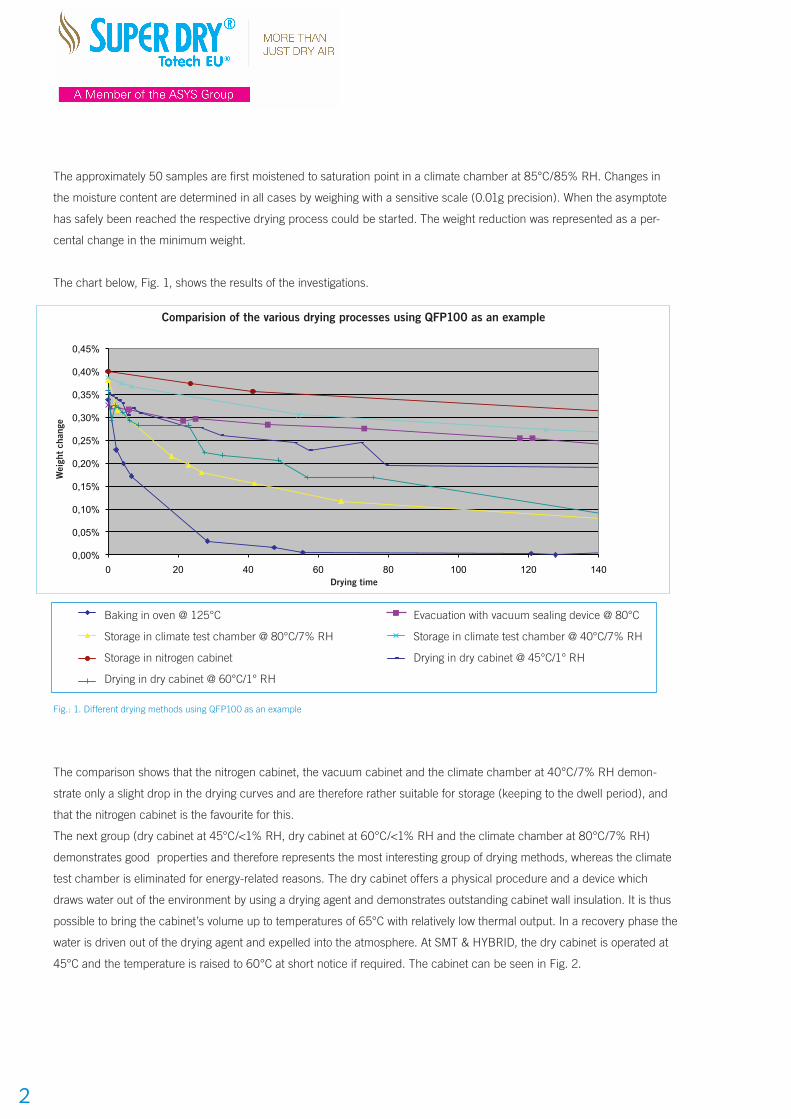
The approximately 50 samples are first moistened to saturation point in a climate chamber at 85°C/85% RH. Changes in
the moisture content are determined in all cases by weighing with a sensitive scale (0.01g precision). When the asymptote
has safely been reached the respective drying process could be started. The weight reduction was represented as a per-
cental change in the minimum weight.
The chart below, Fig. 1, shows the results of the investigations.
Fig.: 1. Different drying methods using QFP100 as an example
The comparison shows that the nitrogen cabinet, the vacuum cabinet and the climate chamber at 40°C/7% RH demon-
strate only a slight drop in the drying curves and are therefore rather suitable for storage (keeping to the dwell period), and
that the nitrogen cabinet is the favourite for this.
The next group (dry cabinet at 45°C/<1% RH, dry cabinet at 60°C/<1% RH and the climate chamber at 80°C/7% RH)
demonstrates good properties and therefore represents the most interesting group of drying methods, whereas the climate
test chamber is eliminated for energy-related reasons. The dry cabinet offers a physical procedure and a device which
draws water out of the environment by using a drying agent and demonstrates outstanding cabinet wall insulation. It is thus
possible to bring the cabinet’s volume up to temperatures of 65°C with relatively low thermal output. In a recovery phase the
water is driven out of the drying agent and expelled into the atmosphere. At SMT & HYBRID, the dry cabinet is operated at
45°C and the temperature is raised to 60°C at short notice if required. The cabinet can be seen in Fig. 2.
2
Comparision of the various drying processes using QFP100 as an example
Drying time
Wei
ght
chan
ge
0,00%
0,05%
0,10%
0,15%
0,20%
0,25%
0,30%
0,35%
0,40%
0,45%
0 20 40 60 80 100 120 140
Wei
ght c
hang
e
Drying time
Comparison of the various drying processes using QFP100 as an example
Trocknung im Ofen @ 125°C Evakuierung Vakuumschweissgerät @80 °C
Lagerung im Klimaschrank @ 80°C/7% r.F. Lagerung im Klimaschrank @ 40°C/7% r.F.
Lagerung im Stickstoffschrank Trocknung im Trockenschrank @ 45° >1°r.F.
Trocknung im Trockenschrank @ 60°C >1°r.F.
Baking in oven @ 125°C Evacuation with vacuum sealing device @ 80°C
Storage in climate test chamber @ 80°C/7% RH Storage in climate test chamber @ 40°C/7% RH
Storage in nitrogen cabinet Drying in dry cabinet @ 45°C/1° RH
Drying in dry cabinet @ 60°C/1° RH
In manufacturing practice, neither the percental initial weight or the minimum weight but rather the time is available as the
benchmark for drying. This time was defined as drying time.
4. Experiments in drying circuit boards
First, it is necessary to attempt to develop basic methods for drying circuit boards by means of the circuit boards specially
used here. The investigations carried out here with the limited spectrum of very specific circuit boards represent just the
beginning of the experiments and serve to infer some fundamental questions.
After the preliminary experiments described above, selected drying experiments were performed in the dry cabinet at
45°C/< 1% RH and also 60°C / <1% RH and corresponding baking experiments in the oven at 130°C / < 5% RH.
The methodology has already been described above.
The following circuit boards from one circuit board manufacturer were used as circuit board material.
1. FR4 rigid circuit boards 0.4 thick
2. Flexible triple-layer circuit boards 0.3 thick
3. Rigid-flex circuit boards 0.3/1.4 thick
4. Rigid dual-layer FR4 circuit boards 1.6 thick
5. QFP 100 comparison specimen
The circuit boards were arranged in racks or as bulk goods in appropriate bowls.
Moistening was done using the same method described above.
Drying was subsequently performed under defined conditions.
The drying curves for 45°C/ <1% RH are shown in Fig. 3.
The drying curves indicate that significantly faster drying is
possible at 60°C.
Baking in the oven at 125°C represents a propagated extreme-
ly fast drying method which, however, demonstrates limits and
is not gentle drying as mentioned above. Without doubt the
125°C curve demonstrates the strongest fall-off. The compon-
ents should only be baked at 125 °C if it is necessary to put a
series awaiting assembly into production quickly. Care should
be taken that the cumulative tempering time does not exceed
96 h under any circumstances [2]. This means documentation
must be recorded during series production.
Moisture absorption and drying are diffusion processes and
follow the laws of molecular diffusion [2]. Theoretical observa-
tions are, however, of little use in determining drying times. A
simplified approach is therefore needed.
Moisture must be reduced below 0.1% of the component dry
weight, and the time needed to accomplish this is a critical
process parameter [3].
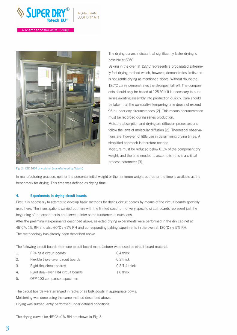
Fig. 2: XSD 1404 dry cabinet (manufactured by Totech)
3
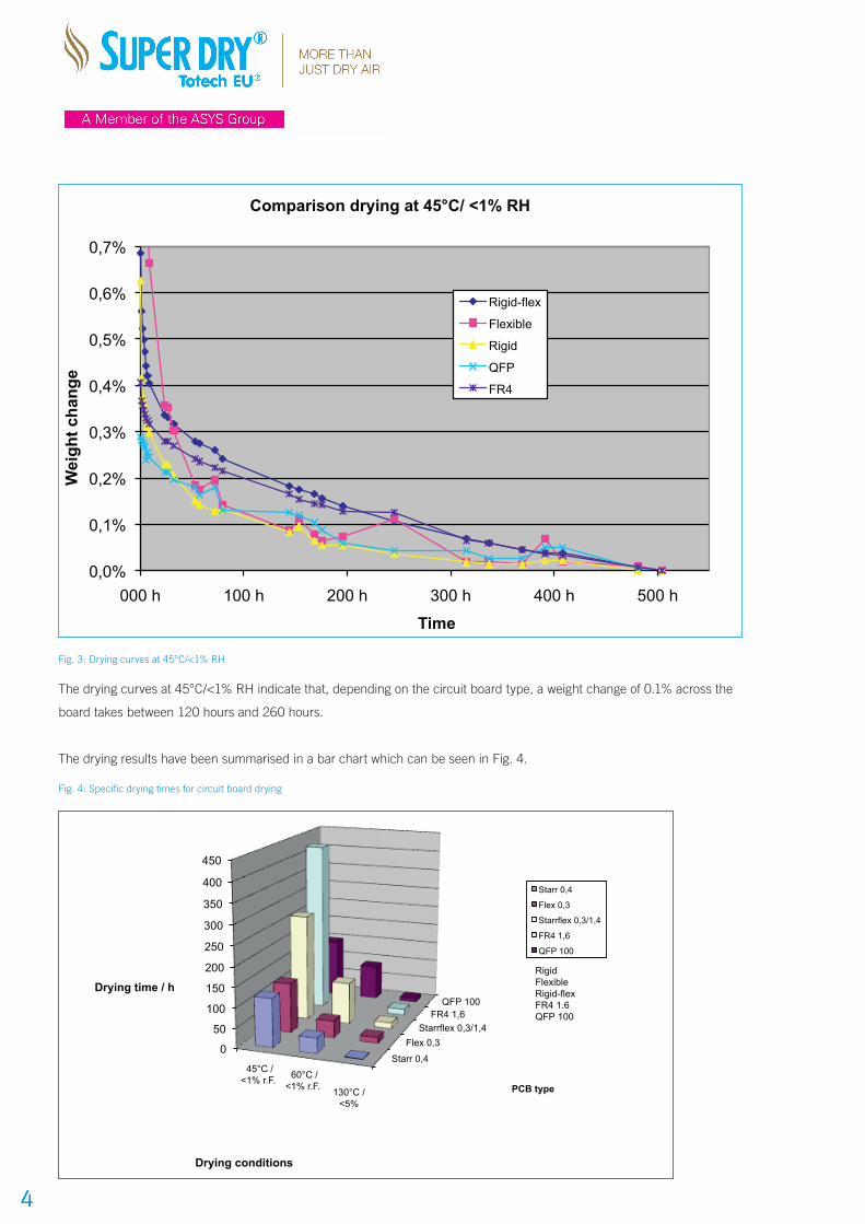
Fig. 3: Drying curves at 45°C/<1% RH
The drying curves at 45°C/<1% RH indicate that, depending on the circuit board type, a weight change of 0.1% across the
board takes between 120 hours and 260 hours.
The drying results have been summarised in a bar chart which can be seen in Fig. 4.
Fig. 4: Specific drying times for circuit board drying
4
0,0%
0,1%
0,2%
0,3%
0,4%
0,5%
0,6%
0,7%
000 h 100 h 200 h 300 h 400 h 500 h
Wei
ght c
hang
e
Time
Comparison drying at 45°C/ <1% RH
Rigid-flex
Flexible
Rigid
QFP
FR4
Starr 0,4
Flex 0,3 Starrflex 0,3/1,4
FR4 1,6 QFP 100
0
50
100
150
200
250
300
350
400
450
45°C / <1% r.F. 60°C /
<1% r.F. 130°C / <5%
PCB type
Drying time / h
Drying conditions
Specific drying times for PCB drying from saturation to 0.1 weight %
Starr 0,4
Flex 0,3
Starrflex 0,3/1,4
FR4 1,6
QFP 100
Rigid Flexible Rigid-flex FR4 1.6 QFP 100
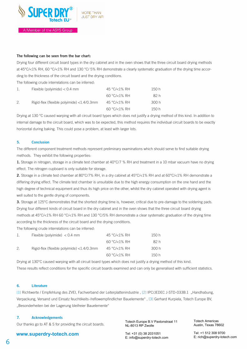
The following can be seen from the bar chart:
Drying four different circuit board types in the dry cabinet and in the oven shows that the three circuit board drying methods
at 45°C/<1% RH, 60 °C/<1% RH and 130 °C/ 5% RH demonstrate a clearly systematic graduation of the drying time accor-
ding to the thickness of the circuit board and the drying conditions.
The following crude interrelations can be inferred:
1. Flexible (polyimide) < 0.4 mm 45 °C/<1% RH 150 h
60 °C/<1% RH 82 h
2. Rigid-flex (flexible polyimide) <1.4/0.3mm 45 °C/<1% RH 300 h
60 °C/<1% RH 150 h
Drying at 130 °C caused warping with all circuit board types which does not justify a drying method of this kind. In addition to
internal damage to the circuit board, which was to be expected, this method requires the individual circuit boards to be exactly
horizontal during baking. This could pose a problem, at least with larger lots.
5. Conclusion
The different component treatment methods represent preliminary examinations which should serve to find suitable drying
methods. They exhibit the following properties:
1. Storage in nitrogen, storage in a climate test chamber at 40°C/7 % RH and treatment in a 10 mbar vacuum have no drying
effect. The nitrogen cupboard is only suitable for storage.
2. Storage in a climate test chamber at 80°C/7% RH, in a dry cabinet at 45°C/<1% RH and at 60°C/<1% RH demonstrate a
differing drying effect. The climate test chamber is unsuitable due to the high energy consumption on the one hand and the
high degree of technical equipment and thus its high price on the other, whilst the dry cabinet operated with drying agent is
well suited to the gentle drying of components.
3. Storage at 125°C demonstrates that the shortest drying time is, however, critical due to pre-damage to the soldering pads.
Drying four different kinds of circuit board in the dry cabinet and in the oven shows that the three circuit board drying
methods at 45°C/<1% RH 60 °C/<1% RH and 130 °C/5% RH demonstrate a clear systematic graduation of the drying time
according to the thickness of the circuit board and the drying conditions.
The following crude interrelations can be inferred:
1. Flexible (polyimide) < 0.4 mm 45 °C/<1% RH 150 h
60 °C/<1% RH 82 h
2. Rigid-flex (flexible polyimide) <1.4/0.3mm 45 °C/<1% RH 300 h
60 °C/<1% RH 150 h
Drying at 130°C caused warping with all circuit board types which does not justify a drying method of this kind.
These results reflect conditions for the specific circuit boards examined and can only be generalised with sufficient statistics.
6. Literature
[1] Richtwerte / Empfehlung des ZVEI, Fachverband der Leiterplattenindustrie , [2] IPC/JEDEC J-STD-033B.1 „Handhabung,
Verpackung, Versand und Einsatz feuchtikeits-/reflowempfindlicher Bauelemente“ , [3] Gerhard Kurpiela, Totech Europe BV,
„Besonderheiten bei der Lagerung bleifreier Bauelemente“
7. Acknowledgements
Our thanks go to AT & S for providing the circuit boards. Totech Europe B.V Paxtonstraat 11NL-8013 RP Zwolle
Tel: +31 (0) 38 2031051E: [email protected]
6
Totech Americas Austin, Texas 78602
Tel: +1 512 308 9700E: [email protected]
www.superdry-totech.com