Embed Size (px)
Citation preview

Development of 2D XFEM Capability for VAST – Phase 2
Brian Yuen Martec Limited Prepared By: Martec Limited 1888 Brunswick Street, Suite 400 Halifax, NS B3J 3J8 Contractor's Document Number: TR-16-44 Rev 01 Contract Project Manager: David Whitehouse, 902-425-5101 PWGSC Contract Number: W7707-145679/001/HAL Technical Authority: Ian Thompson, 902-426-3100 Disclaimer: The scientific or technical validity of this Contract Report is entirely the responsibility of the Contractor and the contents do not necessarily have the approval or endorsement of the Department of National Defence of Canada.
Contract Report DRDC-RDDC-2016-C334 November 2016

© Her Majesty the Queen in Right of Canada, as represented by the Minister of National Defence, 2016
© Sa Majesté la Reine (en droit du Canada), telle que représentée par le ministre de la Défense nationale, 2016

Applied Technology Group tel. 902.425.51011888 Brunswick Street, Suite 400 fax. 902.421.1923
Halifax, Nova Scotia B3J 3J8 Canada email. [email protected]/atg
WWorking together ffor a safer world
Development of 2D XFEM Capability for VAST – Phase 2
Technical Report # TR-16-44 Rev 01 Control Number: 14.28008.1123 and 1135
November 2016
Prepared for:
DRDC – Atlantic P.O. Box 1012 9 Grove Street
Dartmouth, Nova Scotia Canada B2Y 3Z7

Martec Limited is a member of the Lloyd’s Register Group, doing business as the Applied Technology Group

REVISION CONTROL
REVISION REVISION DATE00 16 September 201601 9 November 2016

PROPRIETARY NOTICE
This report was prepared under W7707-145679/001/HAL for DRDC – Atlantic.
The information contained herein may be used and/or further developed by Dfor their purposes only.
Complete use and disclosure limitations are contained in W7707-145679/001/HAL.


EXECUTIVE SUMMARY
The current 2D XFEM capability in VAST only permits a single crack in a flat or slightly curved plate to be modelled in each FE model. However, in practical fracture mechanics problems in ship structures, cracks involving multiple intersecting structural members, such as deck and bulkhead or deck and stiffeners, are commonly seen and multiple cracks might need to be included in the same analysis. In order to provide a more effective capability for fracture analyses of ship structures, attempts were made in this task to extend the current 2D XFEM element in VAST to deal with these crack geometries. These include:
1. Investigation of the use of the level set functions to help to simplify the crackdefinitions in structures with multiple cracks or intersecting cracks.
2. Extension of the 2D XFEM element to permit multiple cracks in the model.
3. Initiation of the extension of the 2D XFEM element to treat intersecting cracks in thesame plane or cracks in intersecting structural members involving branches in differentplanes.
The implementation of the multiple and intersecting crack modelling capability was based on the assumption that the cracks and their associated crack enrichment fields can be superimposed on the element without any modifications to the enrichment formulations and that the interactions between the cracks are accounted for in the minimization of the potential energy in the finite element method. The implementation of the level set functions and the multiple crack modelling capability has undergone an initial verification and appeared to be satisfactory.
In order to further improve the usability of the 2D XFEM element in VAST, it is recommended that future work should include:
1. Completion of the implementation of the level set functions and the intersecting cracksmodelling capability.
2. Further verification and validation of the multiple cracks and intersecting cracksmodelling capabilities.
3. Automatic assignment of the crack enrichment fields.
4. Removal of the restriction on the number of cracks allowed in a model.
5. Improvement of the pre- and post-processing capabilities of TRIDENT toaccommodate the new 2D XFEM capabilities.

TABLE OF CONTENTS 1.0 INTRODUCTION ......................................................................................................................................... 1 2.0 INVESTIGATION INTO THE USE OF LEVEL SET FUNCTIONS IN 2D XFEM .............................. 3
2.1 THEORETICAL DERIVATION ......................................................................................................................... 3 2.2 IMPLEMENTATION IN VAST ........................................................................................................................ 4 2.3 NUMERICAL VERIFICATION ......................................................................................................................... 5
3.0 EXTENSION OF 2D XFEM CAPABILITY TO ALLOW MULTIPLE CRACKS ................................ 7 3.1 THEORETICAL DERIVATION ......................................................................................................................... 7 3.2 IMPLEMENTATION IN VAST ........................................................................................................................ 7 3.3 NUMERICAL VERIFICATION ......................................................................................................................... 8
4.0 INITIATION OF THE EXTENSION OF 2D XFEM CAPABILITY TO ALLOW INTERSECTING CRACKS ................................................................................................................................................................ 12
4.1 THEORETICAL DERIVATION ....................................................................................................................... 12 4.2 IMPLEMENTATION IN VAST ...................................................................................................................... 12 4.3 NUMERICAL VERIFICATION ....................................................................................................................... 13
4.3.1 Plate with a 30° Slanted Centre Crack ............................................................................................ 13 4.3.2 Plate with a Fine Circular Arc Centre Crack .................................................................................. 15 4.3.3 Plate with a Coarse Circular Arc Centre Crack ............................................................................. 17
5.0 CONCLUSIONS AND RECOMMENDATIONS ..................................................................................... 19 6.0 REFERENCES ............................................................................................................................................ 20 APPENDIX A: INPUT DATA FOR 4-NODED 2D XFEM FRACTURE ELEMENT (IEC = 68)

LIST OF FIGURES FIGURE 2-1: THE TWO ISO-ZERO LEVEL SETS DEFINING THE CRACK GEOMETRY [6]. ................................................. 3 FIGURE 2-2: FE MODEL OF A PLATE WITH A CIRCULAR ARC CENTRE CRACK. ............................................................ 5 FIGURE 2-3: EXAMPLE OF THE NODAL LEVEL SET VALUES IN THE LPT FILE. ............................................................ 6 FIGURE 3-1: THE NEW VARIABLE ICRK IN THE CRACK LINES DEFINITION. ................................................................ 8 FIGURE 3-2: THE NEW VARIABLES NENR AND ICRK IN THE ELEMENT AND CRACK ENRICHMENT DEFINITIONS. ...... 8 FIGURE 3-3: FE MODEL OF A PLATE WITH FOUR CRACKS. ......................................................................................... 9 FIGURE 3-4: THE CRACK ENRICHMENT FIELDS OF THE FOUR CRACKS. .................................................................... 10 FIGURE 3-5: DEFORMED CONFIGURATION OF THE PLATE WITH FOUR CRACKS. ....................................................... 10 FIGURE 4-1: FE MODEL OF A PLATE WITH A 30° SLANTED CENTRE CRACK. ............................................................ 14 FIGURE 4-2: DEFORMED CONFIGURATION OF THE PLATE WITH A 30° SLANTED CENTRE CRACK. ............................ 14 FIGURE 4-3: FE MODEL OF A PLATE WITH A FINE CIRCULAR ARC CENTRE CRACK. .................................................. 15 FIGURE 4-4: DEFORMED CONFIGURATION OF THE PLATE WITH A FINE CIRCULAR ARC CENTRE CRACK. .................. 16 FIGURE 4-5: FE MODEL OF A PLATE WITH A COARSE CIRCULAR ARC CENTRE CRACK. ............................................ 17 FIGURE 4-6: DEFORMED CONFIGURATION OF THE PLATE WITH A COARSE CIRCULAR ARC CENTRE CRACK. ............ 18
LIST OF TABLES TABLE 3-1: SUMMARY OF THE STRESS INTENSITY FACTORS OF THE PLATE WITH FOUR CRACKS. ............................ 11 TABLE 4-1: SUMMARY OF THE STRESS INTENSITY FACTORS OF THE PLATE WITH A 30° SLANTED CENTRE CRACK. . 15 TABLE 4-2: SUMMARY OF THE STRESS INTENSITY FACTORS OF THE PLATE WITH A FINE CIRCULAR ARC CENTRE
CRACK. ........................................................................................................................................................... 16 TABLE 4-3: SUMMARY OF THE STRESS INTENSITY FACTORS OF THE PLATE WITH A COARSE CIRCULAR ARC CENTRE
CRACK. ........................................................................................................................................................... 18

Development of 2D XFEM Capability for VAST – Phase 2 1
TR-16-44
1.0 INTRODUCTION
The modelling of fracture and material damage has been a problem of significant interest in solid mechanics for a long time. This is because crack initiation and propagation are important factors that need to be considered in design and maintenance of practical engineering systems. One example is the accurate prediction of fatigue crack propagation in ship structures subjected to spectral loading conditions. Many finite element formulations have been proposed for fracture mechanics analyses over the years. However, all the classical finite element approaches have a common disadvantage: they require the crack be explicitly modelled in the finite element mesh, which can be very challenging. In addition, to simulate crack propagation, continuous re-meshing has to be performed. In order to minimize the requirement of re-meshing during crack propagation analysis, a new finite element formulation, named the extended finite element method (XFEM) has been developed. Compared with earlier numerical methods for fracture mechanics, XFEM has a number of advantages, including (a) it does not require the cracks be explicitly modelled, so no or minimal re-meshing is needed for crack propagation; (b) it is a finite element method, so it can be implemented in existing general-purpose finite element programs such as VAST; (c) in contrast to boundary elements, it is readily applicable to non-linear problems; (d) in contrast to finite elements with re-meshing, it does not require as many projections between different meshes. Under W7707-088100 Tasks 2, 11 and W7707-125422 Task 1, LRATG implemented a 2D XFEM fracture mechanics analysis capability for the VAST finite element code [1-3]. This method for calculation of stress intensity factors was verified using a large number of test cases involving straight, curved and kinked cracks. An extensive numerical study had been performed to investigate the sensitivity of the results to the numerical integration orders and a domain interaction integration algorithm had been incorporated for accurate calculation of the stress intensity factors for mixed mode fracture mechanics problems. The 2D XFEM element was further generalized to allow arbitrary orientation and slight curvature. The 2D XFEM pre-processor, which was initially developed at the early stage of 2D XFEM implementation, has been incorporated into TRIDENT for quick generation of XFEM models and a post-processing capability has also been development in TRIDENT to display XFEM results. The current 2D XFEM element in VAST has been validated through a case study involving prediction of crack growth rate on a naval ship under spectral loading conditions. The results of fatigue calculation based on XFEM generated stress intensity factors were in good agreement with the measured data. Recently, the ability to degenerate the 4-noded quadrilateral XFEM element into a 3-noded triangle was developed in Task 12 of the current contract in order to improve the usability of the 2D XFEM capability for analyzing complex engineering structures [4]. Although the current 2D XFEM capability in VAST has been extensively verified and proved to be reliable, it still contains some serious limitations. For instance, the current XFEM capability only permits a single crack in a flat or slightly curved plate to be modelled in each FE model. In practical fracture mechanics problems in ship structures, cracks involving multiple intersecting structural members, such as deck and bulkhead or deck and stiffeners, are

Development of 2D XFEM Capability for VAST – Phase 2 2
TR-16-44
commonly seen and multiple cracks might need to be included in the same analysis. In order to provide a more effective capability for fracture analyses of ship structures, the current 2D XFEM element in VAST must be extended to deal with these crack geometries. In the current phase of 2D XFEM capability development, the following tasks were performed:
1. Investigate the use of the level set functions to help to simplify the crack definitions in structures with multiple cracks or intersecting cracks.
2. Extend the 2D XFEM element to permit multiple cracks in the model.
3. Initiate the extension of the 2D XFEM element to treat intersecting cracks in the same plane or cracks in intersecting structural members involving branches in different planes.
4. Conduct verification and validation on the newly developed 2D XFEM capability for treating structures with multiple cracks.
Development of 2D XFEM Capability for VAST – Phase 2 3
TR-16-44
2.0 INVESTIGATION INTO THE USE OF LEVEL SET FUNCTIONS IN 2D XFEM
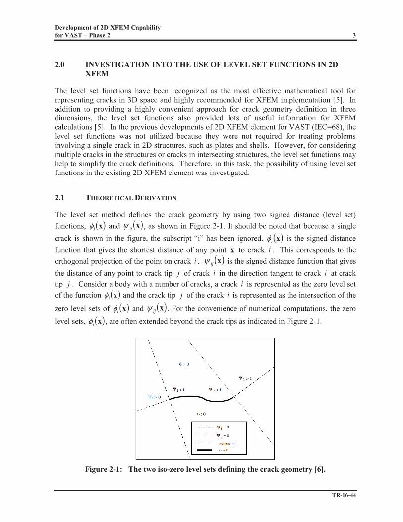
The level set functions have been recognized as the most effective mathematical tool for representing cracks in 3D space and highly recommended for XFEM implementation [5]. In addition to providing a highly convenient approach for crack geometry definition in three dimensions, the level set functions also provided lots of useful information for XFEM calculations [5]. In the previous developments of 2D XFEM element for VAST (IEC=68), the level set functions was not utilized because they were not required for treating problems involving a single crack in 2D structures, such as plates and shells. However, for considering multiple cracks in the structures or cracks in intersecting structures, the level set functions may help to simplify the crack definitions. Therefore, in this task, the possibility of using level set functions in the existing 2D XFEM element was investigated.
2.1 THEORETICAL DERIVATION
The level set method defines the crack geometry by using two signed distance (level set) functions, xi and xij , as shown in Figure 2-1. It should be noted that because a single crack is shown in the figure, the subscript “i” has been ignored. xi is the signed distance function that gives the shortest distance of any point x to crack i . This corresponds to the orthogonal projection of the point on crack i . xij is the signed distance function that gives the distance of any point to crack tip j of crack i in the direction tangent to crack at crack tip . Consider a body with a number of cracks, a crack i is represented as the zero level set of the function xi and the crack tip j of the crack i is represented as the intersection of the
zero level sets of xi and xij . For the convenience of numerical computations, the zero level sets, xi , are often extended beyond the crack tips as indicated in Figure 2-1.
Figure 2-1: The two iso-zero level sets defining the crack geometry [6].
ij
Development of 2D XFEM Capability for VAST – Phase 2 4
TR-16-44
Furthermore, since the level set functions are orthogonal to each other at their intersections, they create the needed coordinate system naturally to facilitate the computation of the nodal enrichments. The conditions in the Heaviside function for crack i can be evaluated based on
xi , such that the Heaviside function can be written as:
otherwise 10 if 1 x
x iiH (1)
In addition, the polar coordinates in the crack tip displacement field for crack tip j of crack ican be computed as:
xxxxxx
ij
iijijiij ,r 122 tan (2)
which can be readily used to evaluate the crack tip enrichment functions.
2.2 IMPLEMENTATION IN VAST
In the current implementation of 2D XFEM in VAST, the information pertaining to the crack geometry is carried into the 2D XFEM element subroutine ELMA68 to determine the orientation of the element nodes with respect of the crack, to determine whether or not the element is intersected by the crack, to subdivide the element into sub-triangles if it is intersected, and to determine the numerical integration points in the element. This requires an inverse mapping algorithm to solve global coordinates of the integration points in the sub-triangles for the corresponding parametric coordinates in the original element. In addition, if there are multiple cracks in a structure, an element could be enriched by more than one crack, each of them needs to have a different set of integration points. This could cause additional difficulties in the numerical integration for computation of the stiffness matrix and the J-integral. The level set method could be used to facilitate the above operations. The values of the level set functions xi and xij could be calculated at a pre-processing stage and stored at nodes before ELMA68 is called. Therefore, any information needed for XFEM, such as the location of the crack line and tip(s), could be obtained from these nodal values, making it unnecessary to carry any other information pertaining to the cracks into the element subroutine ELMA68. In addition, the level set functions could be interpolated over the element by the same shape functions as the displacement, so the values of the enrichment functions can be computed at any numerical integration point. Finally, the nodal level set values could potentially be used to facilitate the automatic assignment of nodal enrichment functions, eliminating the need for the user’s input. For example, nodes that are within a certain distance

Development of 2D XFEM Capability for VAST – Phase 2 5
TR-16-44
from a crack tip could be enriched by the crack tip function. This automatic assignment of nodal enrichment functions could be investigated in the future. In the present investigation and the first step in the implementation of the level set functions into 2D XFEM in VAST, the level set functions are still evaluated in ELMA68 using the existing crack description. For any enriched node, each crack line making up the crack is searched and the value of is assigned as the smallest signed distance from a crack line to the node. is the signed distance of the node to crack tip j of crack in the direction tangent to crack at crack tip j . The level set values are then written to the VAST output file (LPT file) for all the enriched nodes. To realize the full potential of the level set method, the nodal level set values will need to be calculated in a pre-processor before ELMA68 is called. This way, the geometry of the cracks can be obtained by interpolating the nodal level set values using the element shape functions. This will make the computations more efficient, but will require some major revisions to ELMA68 as well as other subroutines such as ELEMS1, which is the subroutine that calls ELMA68 for generating element stiffness and mass matrices.
2.3 NUMERICAL VERIFICATION
The present initial implementation of the level set functions into 2D XFEM in VAST was verified using a plate with a circular arc centre crack as shown in Figure 2-2. The crack was superimposed onto an underlying 100×100 uniform mesh of quadrilateral 2D XFEM elements. Figure 2-3 shows an example of the nodal level set values printed in the LPT file for a typical element in the model. The level set values of a few nodes were calculated by hand using equations (1) and (2) and they matched the values calculated by VAST. This indicated that the nodal level set values are calculated correctly in the present implementation.
Figure 2-2: FE model of a plate with a circular arc centre crack.
ixi
xij ii

Development of 2D XFEM Capability for VAST – Phase 2 6
TR-16-44
Figure 2-3: Example of the nodal level set values in the LPT file.

Development of 2D XFEM Capability for VAST – Phase 2 7
TR-16-44
3.0 EXTENSION OF 2D XFEM CAPABILITY TO ALLOW MULTIPLE CRACKS
In the previous implementations of the 2D XFEM element in VAST, only one crack can be modelled in each FE model. However, in practical fracture mechanics problems in ship structures, cracks involving multiple intersecting structural members, such as deck and bulkhead or deck and stiffeners, are commonly seen and multiple cracks might need to be included in the same analysis. Therefore, in order to provide a more effective capability for fracture analyses of ship structures, in this task, the current 2D XFEM element was extended to permit inclusion of multiple cracks in a FE model.
3.1 THEORETICAL DERIVATION
A detailed description of the theoretical formulation of XFEM can be found in [1]. Briefly, the use of XFEM for crack modelling in VAST is based on enriching the elements in the interior of a crack by the discontinuous Heaviside function and enriching the elements near the crack tip by the asymptotic displacement field. The crack enrichment fields for a single crack have been implemented for the 2D XFEM element in VAST in the previous tasks. In this task to permit the modelling of multiple cracks in a FE model, it is assumed that the enrichment fields associated with each crack do not overlap. That is, each crack is assumed to enrich its own affected elements using the same formulations derived previously for problems involving a single crack. In addition, it is assumed that the interactions between the cracks are automatically accounted for through minimization of the potential energy in the finite element method.
3.2 IMPLEMENTATION IN VAST
The present implementation of multiple cracks modelling capability into 2D XFEM in VAST involved the following major modifications to the code:
The input data format was modified to allow for the definitions of the geometry of more than one crack and to allow an element to be enriched by more than one crack. In the crack lines definition, a new variable, named ICRK, was added to indicate which crack each crack line belongs to (See Figure 3-1). In this figure, crack #1 (ICRK = 1) is made up of two segments. The first segment is the crack line joining nodes 1682 and 1683. Node 1 of this line (node 1682) is a crack tip. The second segment is the crack line joining nodes 1683 and 1684. Node 2 of this line (node 1684) is a crack tip. Crack #2 (ICRK = 2) is similarly defined. Details of the modified input data format can be found in Appendix A.
In the element definition, the variable NENR was added to indicate the number of cracks associated with the current element (See Figure 3-2). In the crack enrichment definition for an enriched element, the variable ICRK was added to indicate which crack the current element belongs to (See Figure 3-2). For the element in this figure,

Development of 2D XFEM Capability for VAST – Phase 2 8
TR-16-44
the element is enriched by one crack only (NENR = 1). The next NENR lines are the enrichment fields. For this element, it is enriched by crack #1 (ICRK = 1) with a crack tip node of 1684 and enrichment field codes of 1 3 0 0. For this element, the parameters KODE, NEXG and INCR have default values (of zero) and are not needed to be assigned values explicitly in the input data. Details of the modified input data format can be found in Appendix A.
An additional dimension was added to various variables, such as the crack tip node number and the crack enrichment flags, in order to store the respective data per crack in the model.
A DO-loop over the number of cracks in the model was added in STRESS1 for identifying elements involved in J-integral for each crack, calculating stresses and other parameters for J-integral, and reporting the results such as the stress intensity factors and crack propagation angles.
It should be noted that in the present implementation of the multiple cracks modelling capability, each element is allowed to be enriched by at most one crack enrichment field. That is, the crack enrichment fields for each crack cannot overlap each other. Because of this restriction, the number of degrees of freedom per node does not have to be increased and the model can have any number of cracks. However, in the present implementation, there is no check to ensure that crack enrichment fields of each crack do not overlap each other. It is up to the user to not enriching an element by more than one crack enrichment field. If two cracks are very close, then the mesh should be refined so that there is a width of at least two elements between the two cracks. This limitation is expected to be removed in the future phase of XFEM development.
Figure 3-1: The new variable ICRK in the crack lines definition.
Figure 3-2: The new variables NENR and ICRK in the element and crack enrichment
definitions.
3.3 NUMERICAL VERIFICATION
The present implementation of multiple cracks modelling capability into 2D XFEM in VAST was verified using a plate with four cracks in a uniform tensile stress field as shown in Figure 3-3. The four cracks were superimposed onto an underlying 100×100 uniform mesh of

Development of 2D XFEM Capability for VAST – Phase 2 9
TR-16-44
quadrilateral 2D XFEM elements. The four cracks were: (a) circular arc centre crack, (b) slanted edge crack, (c) flat off-centre crack, and (d) kinked edge crack. The crack enrichment fields for each crack are shown in Figure 3-4. A linear static FE analysis was performed. The deformed configuration is shown in Figure 3-5. The Mode I and Mode II stress intensity factors of the four cracks are summarized in Table 3-1. Also summarized in the table are stress intensity factor results for the models having one of the cracks only. It can be seen that, in most cases, the results of the 4-crack model are similar to those of the 1-crack models. The biggest differences between the results are in the circular arc centre crack, which is the shortest in length and is surrounded by the other three cracks in the 4-crack model. The differences are due to the influence of the other three cracks on the circular arc centre crack. Although the results of the 4-crack model and the 1-crack models are not directly comparable, they do indicate that the present implementation of multiple cracks modelling capability has produced reasonable results.
Figure 3-3: FE model of a plate with four cracks.

Development of 2D XFEM Capability for VAST – Phase 2 10
TR-16-44
(a) Crack 1 – Circular Arc Centre Crack (b) Crack 2 – Slanted Edge Crack
(c) Crack 3 – Flat Off-Centre Crack (d) Crack 4 – Kinked Edge Crack
Blue = Crack Tip 1 Enrichment Red = Crack Tip 2 Enrichment Yellow = Heaviside Enrichment
Figure 3-4: The crack enrichment fields of the four cracks.
Figure 3-5: Deformed configuration of the plate with four cracks.

Development of 2D XFEM Capability for VAST – Phase 2 11
TR-16-44
Table 3-1: Summary of the stress intensity factors of the plate with four cracks. Tip 1 Tip 2 KI KII KI KII
Crack Description Method 1-Crack Model
4-Crack Model
1-Crack Model
4-Crack Model
1-Crack Model
4-Crack Model
1-Crack Model
4-Crack Model
1 Circular Arc Centre Crack
Direct 0.477 2.348 4.025 2.734 5.449 3.334 -0.717 -1.177 J-Integral 0.505 2.758 4.534 3.184 6.764 4.110 -1.306 -1.685
2 Slanted Edge Crack
Direct 22.507 23.352 8.190 8.383 J-Integral 22.213 23.073 8.192 8.387
3 Flat Off- Centre Crack
Direct 23.869 25.847 1.649 2.417 24.029 25.198 -1.548 0.202 J-Integral 23.552 25.523 1.640 2.357 23.712 24.844 -1.543 0.175
4 Kinked Edge Crack
Direct 22.808 22.569 6.239 6.178 J-Integral 22.179 21.942 6.463 6.425

Development of 2D XFEM Capability for VAST – Phase 2 12
TR-16-44
4.0 INITIATION OF THE EXTENSION OF 2D XFEM CAPABILITY TO ALLOW INTERSECTING CRACKS
As discussed in Chapter 3, in order to provide a more effective capability for fracture analyses of ship structures, in this task, the extension of the current 2D XFEM element to permit intersecting cracks in the same plane or cracks in intersecting structural members involving branches in different planes was initiated.
4.1 THEORETICAL DERIVATION
In this task to initiate the permission of the intersecting cracks in a FE model, it is again assumed that the presence of other cracks in the model does not affect the formulation of the crack enrichment fields of each crack, as discussed in Chapter 3. However, for intersecting cracks, overlapping crack enrichment fields can no longer be avoided. This requires more effort in the implementation of the capability into VAST, as discussed below.
4.2 IMPLEMENTATION IN VAST
The following modifications were accomplished in the present task for providing an intersecting cracks modelling capability for the 2D XFEM in VAST:
The number of degrees of freedom (DOF) per node was increased to allow an element to be enriched by more than one crack enrichment fields, and thus allowing the crack enrichment fields to overlap each other. However, this limits the number of cracks that can be present in the model. Three DOF are required for each crack enrichment field. In the present implementation, the number of DOF was increased from 9 to 36. This allows 10 cracks to be modelled for each element.
A DO-loop for the number of cracks enriching an element was added in the 2D XFEM element subroutine ELMA68 to read the crack enrichment fields data for each crack enriching the element.
The stresses at the numerical integration points in selected elements are used in the J-integral calculations for each crack. The stresses must account for the contributions from all the crack enrichment fields enriching the element. Therefore, the same integration points must be used for all the crack enrichment fields enriching the element. In the previous XFEM implementation, if an element is intersected by a crack, it is partitioned into subdomains, from which the integration points are determined. However, for an element intersected by more than one crack, element partitioning becomes more complicated. If the element partitioning is performed independently for each crack, a different set of numerical integration points will be generated for each crack. On the other hand, if the element is partitioned by taking into account all the cracks that intersect with the element, the partitioning algorithm may become extremely complex and inefficient. Therefore, in the present implementation,

Development of 2D XFEM Capability for VAST – Phase 2 13
TR-16-44
an attempt was made to replace the element partitioning by either a 20×20 or 40×40 Gaussian quadrature rule to ensure the same integration points are used for all the crack enrichment fields enriching the element. In this implementation, the level set values are evaluated at each numerical integration point for each crack using the corresponding nodal values of the level set functions. The level set values at these integration points are utilized to evaluate the enrichment functions during the numerical integration.
A DO-loop for the number of cracks enriching an element was added in the 2D XFEM
stress subroutine ELMC68B to calculate the stress intensity factors per crack per element, perform J-integral integration per crack, and then report the results including stress intensity factors and crack propagation angles per crack per element.
The following tasks will need to be performed in order to complete the implementation of intersecting cracks modelling capability into 2D XFEM in VAST:
An additional dimension will need to be added to more variables in order to store the respective data per crack in the model.
A DO-loop for the number of cracks enriching an element will need to be added in the ELMA68 subroutine to calculate the level set values at each integration point for the enriched elements not intersected by a crack.
A DO-loop for the number of cracks enriching an element will need to be added in the AXA68B subroutine to compute the strain-displacement matrix using all the enrichments from the cracks enriching the element.
4.3 NUMERICAL VERIFICATION
The verification of the present implementation of the 20×20 and 40×40 Gaussian quadrature rules to replace element partitioning was attempted using the following test cases.
4.3.1 Plate with a 30° Slanted Centre Crack
This test case is a plate with a 30° slanted centre crack as shown in Figure 4-1. The crack was superimposed onto an underlying 100×100 uniform mesh of quadrilateral 2D XFEM elements. A linear static FE analysis was performed for each integration scheme. The deformed configurations of the three integration schemes are compared in Figure 4-2. The Mode I and Mode II stress intensity factors of the crack for the three integration schemes are summarized in Table 4-1. It can be seen that both the deformed configurations and the stress intensity factors compare reasonably well between the three integration schemes, although the run with element partitioning seem to be produce slightly higher stress intensity factors.

Development of 2D XFEM Capability for VAST – Phase 2 14
TR-16-44
Figure 4-1: FE model of a plate with a 30° slanted centre crack.
(a) Element Partition (b) 20×20
(c) 40×40
Figure 4-2: Deformed configuration of the plate with a 30° slanted centre crack.

Development of 2D XFEM Capability for VAST – Phase 2 15
TR-16-44
Table 4-1: Summary of the stress intensity factors of the plate with a 30° slanted centre crack.
Integration Tip 1 Tip 2 Scheme Method KI KII KI KII Element Partition
Direct 8.165 4.496 8.166 4.495 J-Integral 8.428 4.845 8.429 4.844
20×20 Direct 7.948 4.410 7.949 4.409 J-Integral 8.380 4.812 8.382 4.811
40×40 Direct 7.906 4.423 7.907 4.422 J-Integral 8.415 4.838 8.416 4.837
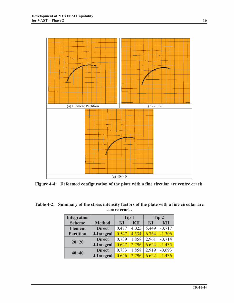
4.3.2 Plate with a Fine Circular Arc Centre Crack
This test case is a plate with a fine circular arc centre crack as shown in Figure 4-3. The crack, made up of 50 segments, was superimposed onto an underlying 100×100 uniform mesh of quadrilateral 2D XFEM elements. A linear static FE analysis was performed for each integration scheme. The deformed configurations of the three integration schemes are compared in Figure 4-4. The Mode I and Mode II stress intensity factors of the crack of the three integration schemes are summarized in Table 4-2. It can be seen that while both the deformed configurations and the stress intensity factors compare reasonably well between the 20×20 and 40×40 Gaussian quadrature integration schemes, they are noticeably different from those produced by the element partition integration scheme. These differences could be caused by the treatment of the curved crack geometry in different analyses. When the Gaussian quadrature schemes were employed, the level set functions were used to describe the crack inside an element, which led to a straight crack segment inside the element domain. However, when the element partitioning algorithm was utilized, the crack geometry was represented with a higher precision [2].
Figure 4-3: FE model of a plate with a fine circular arc centre crack.
Development of 2D XFEM Capability for VAST – Phase 2 16
TR-16-44
(a) Element Partition (b) 20×20
(c) 40×40
Figure 4-4: Deformed configuration of the plate with a fine circular arc centre crack.
Table 4-2: Summary of the stress intensity factors of the plate with a fine circular arc centre crack.
Integration Tip 1 Tip 2 Scheme Method KI KII KI KII Element Partition
Direct 0.477 4.025 5.449 -0.717 J-Integral 0.547 4.534 6.764 -1.306
20×20 Direct 0.739 1.858 2.961 -0.714 J-Integral 0.647 2.796 6.624 -1.435
40×40 Direct 0.733 1.858 2.919 -0.693 J-Integral 0.646 2.796 6.622 -1.436

Development of 2D XFEM Capability for VAST – Phase 2 17
TR-16-44
4.3.3 Plate with a Coarse Circular Arc Centre Crack
In order to test the hypothesis presented in the preceding section, the previous test case was modified to adopt a coarser representation of the curved crack as shown in Figure 4-5, where the crack, made up of 11 segments, was superimposed onto an underlying 100×100 uniform mesh of quadrilateral 2D XFEM elements. The coarse crack model was created by simplifying the fine crack by replacing the curved crack segment within an element by a single straight segment that joins the intersections of the crack to the element edges. This way, the same crack geometry was used in all three runs using either the high order Gaussian quadrature integration schemes or the element partition integration scheme. In these analyses, the regions above and below the crack were always separated by a straight line in a given element. The deformed configurations of the three integration schemes are compared in Figure 4-6. The Mode I and Mode II stress intensity factors of the crack of the three integration schemes are summarized in Table 4-3. Again, it can be seen that while both the deformed configurations and the stress intensity factors compare reasonably well between the 20×20 and 40×40 Gaussian quadrature integration schemes, there are still noticeable differences between them and those from element partition integration scheme. At this point, it is not clear what could be causing the differences and further investigation into the implementation of the Gaussian quadrature integration schemes is needed.
Figure 4-5: FE model of a plate with a coarse circular arc centre crack.

Development of 2D XFEM Capability for VAST – Phase 2 18
TR-16-44
(a) Element Partition (b) 20×20
(c) 40×40
Figure 4-6: Deformed configuration of the plate with a coarse circular arc centre crack.
Table 4-3: Summary of the stress intensity factors of the plate with a coarse circular arc centre crack.
Integration Tip 1 Tip 2 Scheme Method KI KII KI KII Element Partition
Direct 0.584 4.097 5.463 -0.712 J-Integral 0.568 4.553 6.767 -1.300
20×20 Direct 0.771 1.894 2.960 -0.713 J-Integral 0.690 2.838 6.623 -1.430
40×40 Direct 0.772 1.867 2.916 -0.691 J-Integral 0.688 2.822 6.617 -1.432

Development of 2D XFEM Capability for VAST – Phase 2 19
TR-16-44
5.0 CONCLUSIONS AND RECOMMENDATIONS
The current 2D XFEM capability in VAST only permits a single crack in a flat or slightly curved plate to be modelled in each FE model. However, in practical fracture mechanics problems in ship structures, cracks involving multiple intersecting structural members, such as deck and bulkhead or deck and stiffeners, are commonly seen and multiple cracks might need to be included in the same analysis. In order to provide a more effective capability for fracture analyses of ship structures, attempts were made in this task to extend the current 2D XFEM element in VAST to deal with these crack geometries. These include:
1. Investigation of the use of the level set functions to help to simplify the crack definitions in structures with multiple cracks or intersecting cracks.
2. Extension the 2D XFEM element to permit multiple cracks in the model.
3. Initiation of the extension of the 2D XFEM element to treat intersecting cracks in the same plane or cracks in intersecting structural members involving branches in different planes.
The implementation of the multiple and intersecting crack modelling capability was based on the assumption that the cracks and their associated crack enrichment fields can be superimposed on the element without any modifications to the enrichment formulations and that the interactions between the cracks are accounted for in the minimization of the potential energy in the finite element method. The implementation of the level set functions and the multiple crack modelling capability has undergone an initial verification and appeared to be satisfactory. In order to further improve the usability of the 2D XFEM element in VAST, it is recommended that future work should include:
1. Completion of the implementation of the level set functions and the intersecting cracks modelling capability.
2. Further verification and validation of the multiple cracks and intersecting cracks modelling capabilities.
3. Automatic assignment of the crack enrichment fields.
4. Removal of the restriction on the number of cracks allowed in a model.
5. Improvement of the pre- and post-processing capabilities of TRIDENT to accommodate the new 2D XFEM capabilities.

Development of 2D XFEM Capability for VAST – Phase 2 20
TR-16-44
6.0 REFERENCES
(1) Jiang, L. 2010. Implementation of 2D XFEM in VAST. TR-10-10. Applied Technology Group. Halifax, Nova Scotia.
(2) Jiang, L. 2011. Improvement of 2D XFEM in VAST. TR-11-48. Applied Technology
Group. Halifax, Nova Scotia. (3) Jiang, L., and M. Norwood. 2013. Further Development of 2D XFEM in VAST. TR-
13-30. Applied Technology Group. Halifax, Nova Scotia.
(4) Yuen, B. 2015. Development of a Triangular XFEM Element for VAST – Phase 1. TR-15-26. Applied Technology Group. Halifax, Nova Scotia.
(5) Moës, N., A. Gravouil, and T. Belytschko. 2002. “Non-planar 3D Crack Growth by the Extended Finite Element and Level Sets – Part I: Mechanical Model”. International Journal for Numerical Methods in Engineering. Vol. 53, pp. 2549-2568.
(6) Stolarska, M., D. L. Chopp, D. L., N. Moës, and T. Belytschko. 2001. “Modelling Crack Growth by Level Sets in the Extended Finite Element Method”. International Journal for Numerical Methods in Engineering. Vol. 51, pp. 943–960.

APPENDIX A
INPUT DATA FOR 4-NODED 2D XFEM FRACTURE ELEMENT (IEC = 68)

CRACK LINES DEFINITION The following input data are to be provided in the GOM file after the node information: Card 4d (5I5, 3E10.3) (NCKL cards, omit if NCKL =0)
N1, N2 = Structural node numbers defining a crack line. INC = 0, Current crack line does not contain a crack tip. = 1, N1 is at crack tip. = 2, N2 is at crack tip. NC = Crack tip node number to which this crack line is associated. Note: If N2 = 0, N1 will be assumed to be at the crack tip. In this case INC
and NC will be automatically set to 1 and N1 respectively. ICRK = Crack number. DC1, = Direction cosines defining crack orientation, i.e. the direction DC2, along crack and pointing away from crack tip. DC3 Note: DC1, DC2, and DC3 are required only if the crack line is at a crack tip,
and N2 equals 0. If N2 is not equal to zero, the direction of the crack will be computed from the orientation of line N1 – N2 and the direction be determined by the value of INC defined above.

ELEMENT DEFINITION The following input data are to be provided in the element section in the GOM file. Cards for 4-Noded 2D XFEM Fracture Element (IEC = 68)
Supply Card Eb for each of the NELM elements
Card Eb.1 (4I5, 4E10.3, I5, I2, 2I5)
N1→N4 = Element nodes. For nodes that are not enriched, the nodal unknowns contain three translations. For enriched nodes, they also include additional degrees of freedom for the enrichment field.
TK (1) = Thickness at element nodes (length). (If the element is of
↓ constant thickness, supply only TK (1). TK (4) NENR = Number of crack enrichment fields assigned to the element.
Note: Only 0 or 1 is allowed in the current version of VAST. KODE = 0, Element stiffness, geometric stiffeners and mass matrices are
calculated for the current element. = 1, Geometry, orientation and initial stresses of the current
element are same as those of the previous element and the element matrices of the previous element are used for the current element.
NEXG = Number of extra elements generated through incrementation of
node numbers N1 to N4 from element connectivity array. INCR = Integer by which node numbers from previous element
connectivity array are incremented to generate a new element. Card Eb.2 (6I5) (Provide this card for each of the NENR crack enrichment fields; omit if NENR = 0)
ICRK = Crack number.
N5 = Crack tip node. This is only required if at least one node of the element is enriched by the crack tip function.

IENR1→IENR4= Flags to indicate the type of enrichment to be assigned to each
node in the element. IENRI=0 indicates that node I is not enriched. IENRI=1 indicates that node I is enriched with the discontinuous displacement function H(x). IENRI=J (J>1) indicates that node I is enriched with the crack tip asymptotic displacement functions for crack tip J-1 of crack ICRK.