Embed Size (px)
Citation preview
NASA / CR-1998-208729
Determination of Stress Coefficient Terms in
Cracked Solids for Monoclinic Materials
with Plane Symmetry at x 3 - 0
F. G. Yuan
North Carolina State University, Raleigh, North Carolina
National Aeronautics and
Space Administration
Langley Research Center
Hampton, Virginia 23681-2199
Prepared for Langley Research Centerunder Grant NAG1-1981
October 1998
https://ntrs.nasa.gov/search.jsp?R=19990008888 2018-06-04T05:37:29+00:00Z
Available from:
NASA Center for AeroSpace Information (CASI)7121 Standard Drive
Hanover, MD 21076-1320
(301) 621-0390
National Technical Information Service (NTIS)
5285 Port Royal Road
Springfield, VA 22161-2171
(703) 605-6000
71 I
Determination of Stress Coefficient Terms in Cracked Solids
for Monoclinic Materials with Plane Symmetry at X3 = 0
F. G. Yuan
Department of Mechanical and Aerospace Engineering
North Carolina State University
Raleigh, NC 27695
Abstract
Determination of all the coefficients in the crack tip field expansion for monoclinic
materials under two-dimensional deformation is presented in this report. For monoclinic
materials with a plane of material symmetry at x3 = 0, the in-plane deformation is decoupled from
the anti-plane deformation. In the case of in-plane deformation, utilizing conservation laws of
elasticity and Betti's reciprocal theorem, together with selected auxiliary fields, T-stress and
third-order stress coefficients near the crack tip are evaluated first from path-independent line
integrals. To determine the T-stress terms using the J-integral and Betti's reciprocal work
theorem, auxiliary fields under a concentrated force and moment acting at the crack tip are used
respectively. Through the use of the Stroh formalism in anisotropic elasticity, analytical
expressions for all the coefficients including the stress intensity factors are derived in a compact
form that has surprisingly simple structure in terms of one of the Barnett-Lothe tensors, L. The
solution forms for degenerated materials, orthotropic, and isotropic materials are also presented.
Introduction
The use of fracture mechanics to assess the failure behavior in a flawed structure requires
the identification of critical parameters which govern the severity of stress and deformation field
in the vicinity of the flaw, and which can be evaluated using information obtained from the flaw
geometry, loading, and material properties. In the linear elastic solids, stress intensity factors, ki (i
= I, ]I, m), represent the leading singular terms in the Williams eigenfunction expansion series
near a crack tip. ki are often assumed to be unique parameters associated with crack extension.
The physical implications of the higher-order non-singular terms have been noted by Cotterell
(1966). Especially, the so-called T-stress, second term of the crack tip stress field which
represents the constant normal stress parallel to the crack surfaces, has been found as an
additional parameter in characterizing the behavior of a crack (Larsson and Carlsson, 1973; Rice,
1974). Cotterell and Rice (1980) showed that T-stress substantially influences the fracture path
stability of a mode-I crack. The stress biaxiality parameter (Leevers and Radon, 1982; Sham,
1991) has been tabulated as a function of relative crack lengths and overall geometry in many
fracture test specimens for the isotropic solid using computational techniques (e.g., Kfouri, 1986
and Sham, 1989 and 1991). Kardomateas et al. (1993) examined the third-term of the Williams
solution and concluded its significance in the center-cracked and single-edge specimens with
short crack lengths.
In anisotropic linear elastic solids, Gao and Chiu (1992) examined the T-stress term of a
crack in infinite orthotropic solids under mode-I loading. Because of the material anisotropy
involved, theT-stresstermis affectedby thematerialproperties.It is alsoexpectedthat,ingeneral,mixed-modecrackbehaviorandthebiaxialityparameterarealsodependenton thematerialanisotropy.Thus,it is essentialto developefficientcomputationaltechniquestodetermineT-stresstermcoefficients including the stress intensity factors in anisotropic cracked
materials with finite geometry. In this report, two methods based on the J-integral and Betti's
reciprocal theorem are proposed to obtain compact forms in calculating all the stress coefficient
terms in the crack tip field expansion for monoclinic materials with a plane of material symmetry
at x3 - 0. To determine T-stress term using the J-integral, the method by Kfouri (1986) is
extended to anisotropic solids. The closed form solution of the auxiliary field, a point force
acting at the crack tip, is derived for this purpose. A path-independent integral based on the
Betti's reciprocal work concept has been used for determining the stress intensity factors by
Stern, Becker, and Dunham (1976), Hong and Stem (1978), Sinclair, Okajima, and Griffin
(1984) for isotropic materials; Soni and Stem (1976) for orthotropic materials; and An (1987) for
rectlinearly anisotropic materials. This path-independent line integral is also extended to
determine all the stress coefficient terms with auxiliary fields.
Mathematical Formulation
In a fixed Cartesian coordinate system xi, (i = 1, 2, 3), consider a two-dimensional
deformation of an anisotropic elastic body in which the deformation field is independent of the x3
coordinate. In this report, attention focuses on the monoclinic material having three mutually
perpendicular symmetry planes and one of the planes coinciding with the coordinate plane x3 = 0.
In this case, the in-plane and out-of-plane deformations are uncoupled. For in-plane deformationthe strain and stress relations can be written as
e =s'<7 (1)
where e = [e_, e2, y_2] r, o- = [o'_, 6_2, o'_2]r
or
J
e i=s oct j, i,j=I, 2,6
where s U = sji are reduced compliance coefficients defined bys o = sij - si3sj3 [ $33.
Throughout the report, all indices range from 1 to 2 and the summation convention is
applied to repeated Latin index unless otherwise noted. The bold-face letters are used to represent
matrices or vectors. A comma stands for differentiation; overbar denotes complex conjugate. A
symbol Re stands for real part; kn for imaginary part.
In the absence of body forces, general solutions of the displacement vector u, the stress
function _, and stresses _ for in-plane deformation, according to Stroh formalism (Ting, 1996),
can be represented by
:1 | ]'
or
where
u= Re[_.aa,_do, f (z,_)]_=1
2
gp= Re[__b,_d,_f(z,_)]0_=I
(2)
u : Re[A(f (z)>d]
(p : Re[B(f (z))d](3)
cr,, = -_.,2, o'_2 = _,, (4)
<f(z)) = diag[f(z,), f(z2)]
z,_ = xl + I.t,,x2 , Im[_ ] > 0
flz) is an arbitrary function, d is a unknown complex constant vector to be determined./.tc_,
aa, and be, are the Stroh eigenvalues and corresponding eigenvectors determined by elastic
constants only. For in-plane deformation, u_ are given by the roots of the characteristics
equation:
t 2 ,, tS;lr/l 4 -- 2S;6/.t 3 + (2S;_, + $66)],1 - 2s26/.t + s:: =0 (5)
with positive imaginary pans. From energy consideration, Lekhnitskii (1963) showed that the
roots are either complex or purely imaginary and cannot be real. A and B are Stroh matrices
given by
[1 ] [;B=[bl, b2]= , I-tz B_I_ i 11 ' I.tl - I1,. _
t 9
--SI6J"/'a + SI_ ' qa = -$26p_ = . sl2_ + s22/I-t,_. (8)
The eigenvectors aa and ba are unique to an arbitrary multiplier. Introducing normalization
factors ka, we have
A Lkiq, k2q2 j, k, k s J
The values of kc, satisfy the conditions
2a_r b_ = _,_
(9)
Basedon theStrohformalism,thematricesA and B defined in eq. (9) satisfy orthogonality
relations. For in-plane deformation, these relations can be expressed by
where
It can be proved that
BrA+ArB =I (10)
nrA-+ ArB- = 0 (11)
2kl-(ql - pd.tl) = i, 2k2(q2 - p21.t2) = 1
B-r B -_ = -2iL -_ , L-' = -Im[AB -_ ] (12)
where L is a real, symmetric, and positive definite matrix which will be used frequently in thesequel.
Note that the normalization factors cancel each other for the term AB 1 in the second
equation of (12). Therefore there is no need to introduce the normalization factors in computing
L _. From eq. (12)2, it is easy to get
L-I =sll d , L- s(l(be_d2)(13)
I-t_+112. = a + i b , l,lt_z = c + i d ,
e = ad - bc - Im[/.t_/.z 2(_ + _2 )] (14)
For crack problems, it may be convenient to introduce a complex potential function
(Guo, 1991) such that
• =B(U(z))B"g (15)
where g = Bd, then the displacement expression in eq. (3) and stresses in eq. (4) can be rewritten
in terms of the potential function
u=Re[AB4_] (16)
ai_ = -Re[_.2], 0"/2 : Re[_u_] (17)
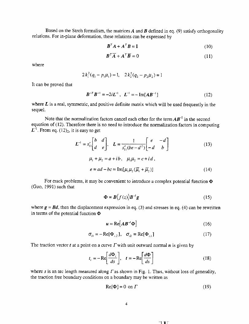
The traction vector t at a point on a curve/"with unit outward normal n is given by
(18)l-d_i -] Reld_]":-ReL-G---sJ''=- L-ds-sJ
where s is an arc length measured along Fas shown in Fig. 1. Thus, without loss of generality,
the traction free boundary conditions on a boundary may be written as
Re[q_] =0 on F (19)
71 Ili
x 2 _ t
x I
Fig. 1 The surface traction t on a curved boundary Fwith a unit outward normal vector n.
The resultant force and moment about the x_ axis due to the surface traction t acting on F
between st and s2 (s2 > st) are
f.%_- t(s) ds = Re[q_(s_ ) - _(s 2)] (20)
-,F(x,,2 -z]l;:where
If Fencloses a region and there are concentrated forcer and moment M inside the region, then
the equilibrium of the body demands that
- Irt(s)ds = f (22)
- ;r (xlt2 - Xzt_)ds = M (23)
Crack-tip fields
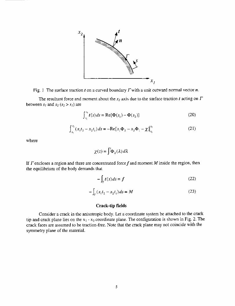
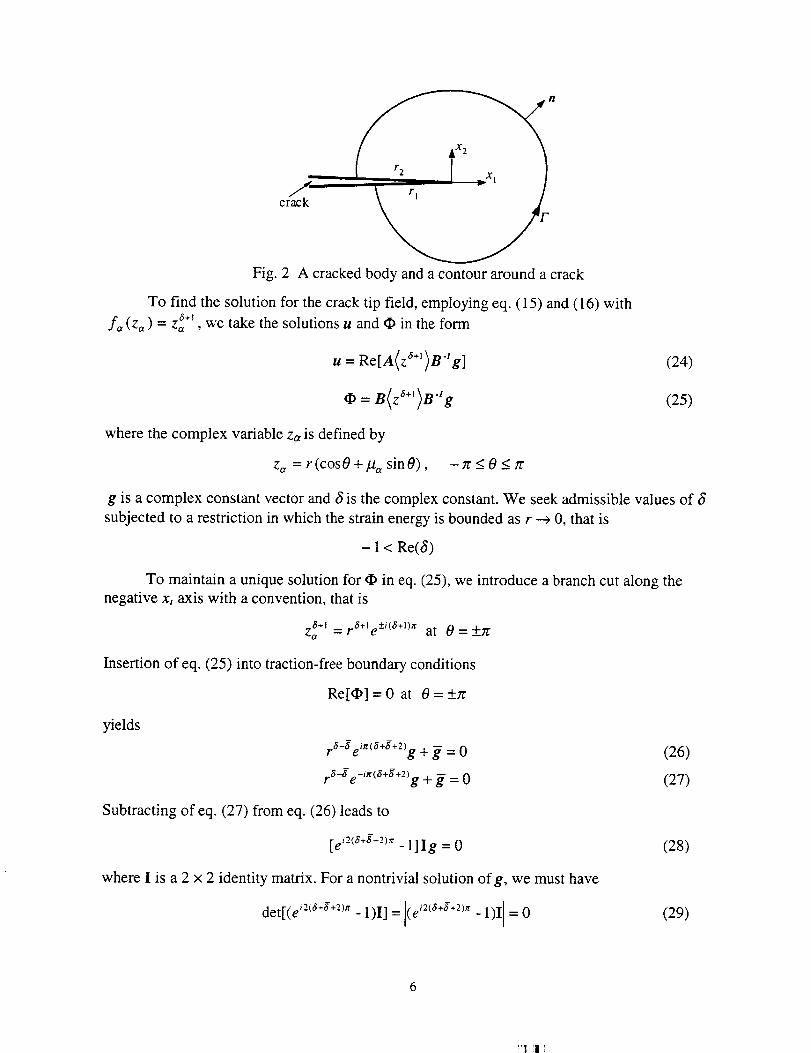
Consider a crack in the anisotropic body. Let a coordinate system be attached to the crack
tip and crack plane lies on the Xl - x3 coordinate plane. The configuration is shown in Fig. 2. The
crack faces are assumed to be traction-free, Note that the crack plane may not coincide with the
symmetry plane of the material.
n
crack
Fig. 2 A cracked body and a contour around a crack
To find the solution for the crack tip field, employing eq. (15) and (16) with
f,, (z,_) = z_ ÷z, we take the solutions u and _ in the form
u= Re[A(z_÷')B4 g]
where the complex variable zc, is defined by
z_, = r(cosO +/.t,, sinO), -_gON_
(24)
(25)
g is a complex constant vector and _5is the complex constant. We seek admissible values of _5
subjected to a restriction in which the strain energy is bounded as r --+ 0, that is
- 1 < Re(S)
To maintain a unique solution for _ in eq. (25), we introduce a branch cut along the
negative x_ axis with a convention, that is
z6+t = F6÷le+_i(6+l)xat 0 = +to
Insertion of eq. (25) into traction-free boundary conditions
Re[_] = 0 at 0 = +:r
(26)
(27)
(28)
(29)
yields
ra-$ ei'_(8+g+2)g + _ = 0
rS-g e-"<_+g+2)g + _ = 0
Subtracting of eq. (27) from eq. (26) leads to
[e i2_5+g÷2)'_- 1]Ig = 0
where I is a 2 × 2 identity matrix. For a nontrivial solution of g, we must have
det[(e i2<a+g+2)_r- 1)I] = l(e - 1)I = 0
or
Re(S)=(n-2)/2, n=1,2,3,... (30)
With eq. (30), from eq. (26) or (27), we have
= --r/2tm('s) cos[27rRe(3)] g (31)
Since _ is a constant, from eq. (31), (30),
Im(8)=0, 3=(n-2)/2 (32)
1 1 3_-= g, 3 22'2
-g, 3=0,1,2,..
that is, 3 is real, the vector g associated with S is real if 3 = -1/2, ½, 3/2, ...; and g is pure
imaginary if 3 = 0, 1, 2 ..... It is clear from the determinant given in eq. (29) that each of the
eigenvalues 3 is a root of multiplicity two. Since g has two arbitrary components, we have two
independent eigenfunctions associated with the double eigenvalues 3. Therefore the assumed
forms of u and _ given by eq. (24) and (25) are justified; no logarithmic type of solution formexists.
Superimposing all the solutions with different orders of r, the crack tip field can be
constructed as
a.+l -1
u= £Re[A(z )B g,]n=l
n=l
(33)
where 3. = (n - 2) / 2. g. is real for n = 1, 3, 5, .--, g. is pure imaginary for n = 2, 4, 6,-.., and g°
are dependent on the geometry of the cracked body, material properties, and loading conditions.
Similarly, there is no need to introduce kc, in calculating ¢Y0and ui from eq. (33).
Performing algebraic calculation and defining g. = [g._, g.2 ]v, the stress and
displacement components can be written as
O'l, ='y__.(3. +l)r a" Re{ 1.=1 /-q /-/,_
_a=Z(3,+l)ra, Re{ 1_=l lat - t-t2
Z (3. + 1)r a" Re I !£Y12_=l (/-q /-/2
[g., (/.tzg_"-/.t_g_" )+ g.z/./l/.t2 (u292a" -/.z,g_" )]}
--b., (d"-¢")+ ,..¢")]} (34)
7
kq2q2 -qlq_ :i)+ g.2Wlqzg2 --/'tzqlqln=l //I -- ///2
(35)
where q,_ = cos 0 +//,_ sin 0.
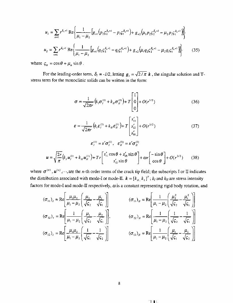
For the leading-order term, Sj = -1/2, letting g_ = .qr_/7r k, the singular solution and T-
stress term for the monoclinic solids can be written in the form:
1 (k,o'_')*/_ ,.rm)+T +O(r ''2)1_" _ _ -- ,_llV ll
(36)
Is;,1
LS,6j
(37)
E(I) t_(l) ,o(l) = eft.t(] )
9__r/..> <,), [s_cosO+s_6sinO ] IcSion:]u =_--_Vczul +kuu. )+Tr +(Or +O(r 3/2)st2 sin 0
(38)
where o"("_ u (n), ,..., are the n-th order terms of the crack tip field; the subscripts I or H indicates
the distribution associated with mode-I or mode-II, k = [k., k_ ]r ; k/and kH are stress intensity
factors for mode-I and mode-II respectively, co is a constant representing rigid body rotation, and
I//2 //_ )](O"')' = Rel-//1-_-2 _2L//1 -//2
//t //2 _ '
- L//,-//2 477,
({_"11)H = Re
(0"22)" = Re
1
1/1 -//2
1
//1 _//2
:l !!
_u.).,=Re[l_(_2_-P"Z'l,,u_
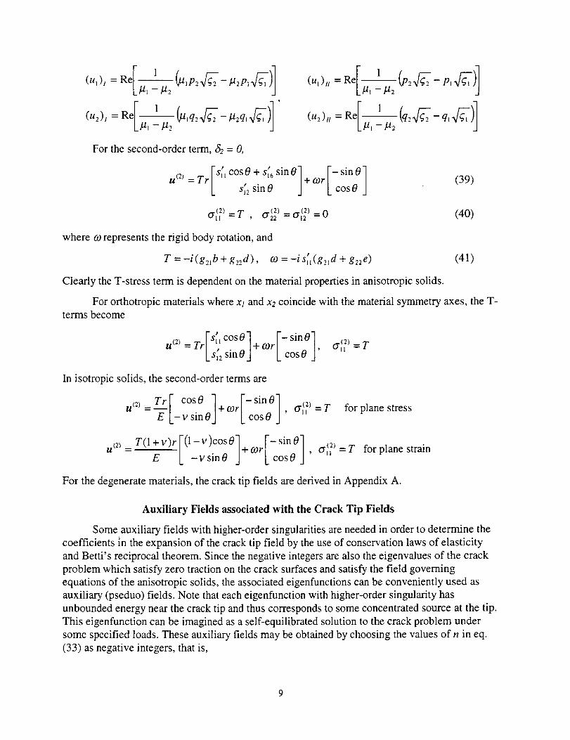
For the second-order term, 62 - 0,
=,r[,: osO,s: sinO]s,no ,or'I- in070 (39)
o'I_ ) = T , o22-_2)= o.I_ = 0 (40)
where co represents the rigid body rotation, and
T = -i (g,_.lb + g,_zd), co = -i s_l(g,.id + g22 e) (41)
Clearly the T-stress term is dependent on the material properties in anisotropic solids.
For orthotropic materials where xl and x2 coincide with the material symmetry axes, the T-
terms become
.Dr,_os0] o_r/-_in0/r1 o_)-rU (2) =lr/ , 14-
I s,2 sin 0 J Lcos0j
In isotropic solids, the second-order terms are
u,=_7"rF cos0l+cor[-Sin01o._?_=T for plane stress="-E-L-v sin0J L cos0 J'
uC2)=T(l+v)r[(1-v)c°sO'+cor[-sinO] cr_'=T for plane strain
E U -vsin0 L cos0 _] '
For the degenerate materials, the crack tip fields are derived in Appendix A.
Auxiliary Fields associated with the Crack Tip Fields
Some auxiliary fields with higher-order singularities are needed in order to determine the
coefficients in the expansion of the crack tip field by the use of conservation laws of elasticity
and Betti's reciprocal theorem. Since the negative integers are also the eigenvalues of the crack
problem which satisfy zero traction on the crack surfaces and satisfy the field governing
equations of the anisotropic solids, the associated eigenfunctions can be conveniently used as
auxiliary (pseduo) fields. Note that each eigenfunction with higher-order singularity has
unbounded energy near the crack tip and thus corresponds to some concentrated source at the tip.
This eigenfunction can be imagined as a self-equilibrated solution to the crack problem under
some specified loads. These auxiliary fields may be obtained by choosing the values of n in eq.
(33) as negative integers, that is,

Re A a,,,_-i B-_
(l)a n/ a,,,+z \ .-.-1.= D \ Z ] lJ rtm
(42)
o 11
cr_1= -Re[O,.2], G2 = Re[O_,_ ] (43)
A,, =-m/2,m= 1,3,4,..., (44)
h m = [h,, I , h,,,.] r
where h,, are arbitrary constant vectors, h mis real for m = 1, 3, 5, .-.; h,, is pure imaginary for m =
4, 6, 8,-.-, Utilizing eq. (22-23), the auxiliary fields, except m = 4, defined by eq. (42) yield zero
resultant force on any contour Fwhich encloses the crack tip shown in Fig. 2. The corresponding
resultant moment about the x_-axis, produced by the tractions acting on the contour Fis also zero
for the auxiliary fields in eq. (42). The special case of A,. = -2 or m = 4 can be also directly
explained from eq. (23). In this case, the function associated with [0, h4_,]r corresponds to the
particular solution for a crack under a concentrated moment about x3-axis, (-2Jr i h42 ), applied at
the crack tip; the function associated with [hat , 0] T corresponds to the homogeneous solution
which satisfies zero concentrated force and moment at the crack tip.
From eq. (42)-(44), the stress and displacement components of the auxiliary fields are
or(. ) { 122 =(An, "+" 1)rA'° Re • -121 fl_
o'_ ° =(A + l)r a'' Re(. 1
L12_ 122
__[hml / Atn ).-_- hm 2 (121_ m dt'n )] t_,g: -g_ .... 12:g,
-- __ _2 _
(45)
__ L02_ 2, _ p,q_,,,.i )+ h.,zW, p2(_2 _ I-t..P,g,.,u l = 12t 122
g
a __ ra.,+t _ 1U2 Re[ 12l - 122
h [ An_+l A,,3 +1 _]1
,_, I,q2q2 q,q_,,,+, )+ ' a.+,-- -- hm2 _-/lq2q2 ' - 122q1_1 J];
(46)
In the following two sections, stress intensity factors, T-stress term, and coefficients of
higher-order terms are determined using the J-integral and the Betti's reciprocal theorem
including the use of above auxiliary fields.
(a) T-stress Term
J-Integral
IO
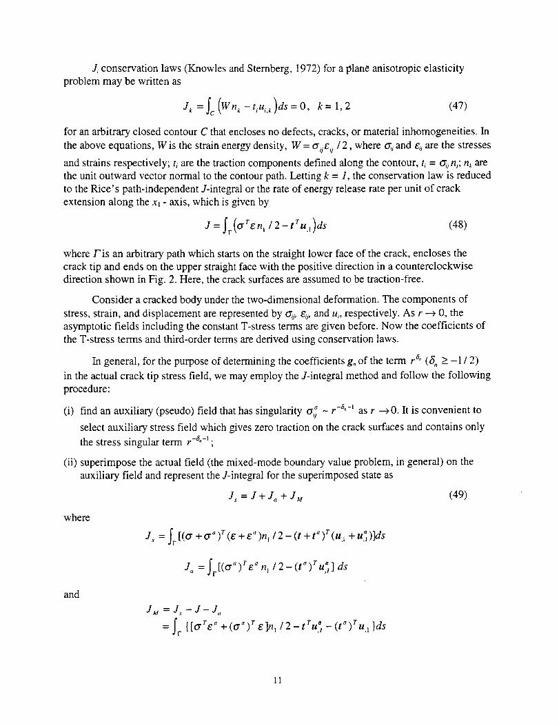
Z conservationlaws(KnowlesandSternberg,1972)for a planeanisotropicelasticityproblemmaybewritten as
J_ = fc (Wnk -tiui.k)ds= 0, k= 1,2 (47)
for an arbitrary closed contour C that encloses no defects, cracks, or material inhomogeneities. In
the above equations, W is the strain energy density, W = oije 0 /2, where _j and e0 are the stresses
and strains respectively; ti are the traction components defined along the contour, t, = _ n_; nk are
the unit outward vector normal to the contour path. Letting k = 1, the conservation law is reduced
to the Rice' s path-independent J-integral or the rate of energy release rate per unit of crack
extension along the xl - axis, which is given by
J = fr(ffren, /2-tru.,)ds (48)
where Fis an arbitrary path which starts on the straight lower face of the crack, encloses the
crack tip and ends on the upper straight face with the positive direction in a counterclockwise
direction shown in Fig. 2. Here, the crack surfaces are assumed to be traction-free.
Consider a cracked body under the two-dimensional deformation. The components of
stress, strain, and displacement are represented by a_i, e_, and u_, respectively. As r _ 0, the
asymptotic fields including the constant T-stress terms are given before. Now the coefficients of
the T-stress terms and third-order terms are derived using conservation laws.
In general, for the purpose of determining the coefficients g° of the term r 6° (ft, > -1 / 2)
in the actual crack tip stress field, we may employ the J-integral method and follow the following
procedure:
(i) find an auxiliary (pseudo) field that has singularity o'_j - r -8°-1 as r --_ 0. It is convenient to
select auxiliary stress field which gives zero traction on the crack surfaces and contains only
the stress singular term r -6"-1 ;
(ii) superimpose the actual field (the mixed-mode boundary value problem, in general) on the
auxiliary field and represent the J-integral for the superimposed state as
where
Js = J + Ja + JM (49)
J, =Ir[(Cr +Cr_)r(e +e_)n_/2 (t +t")r(u_ +u _- ,, )]ds
J, = Ir[(O'") re ° n,/2-(t°)ru_] ds
and
JM =Js-J-J,
=Iv {[°'re_ +(aa)r 6]n'/2-tru_-(t")ru'l}ds
11
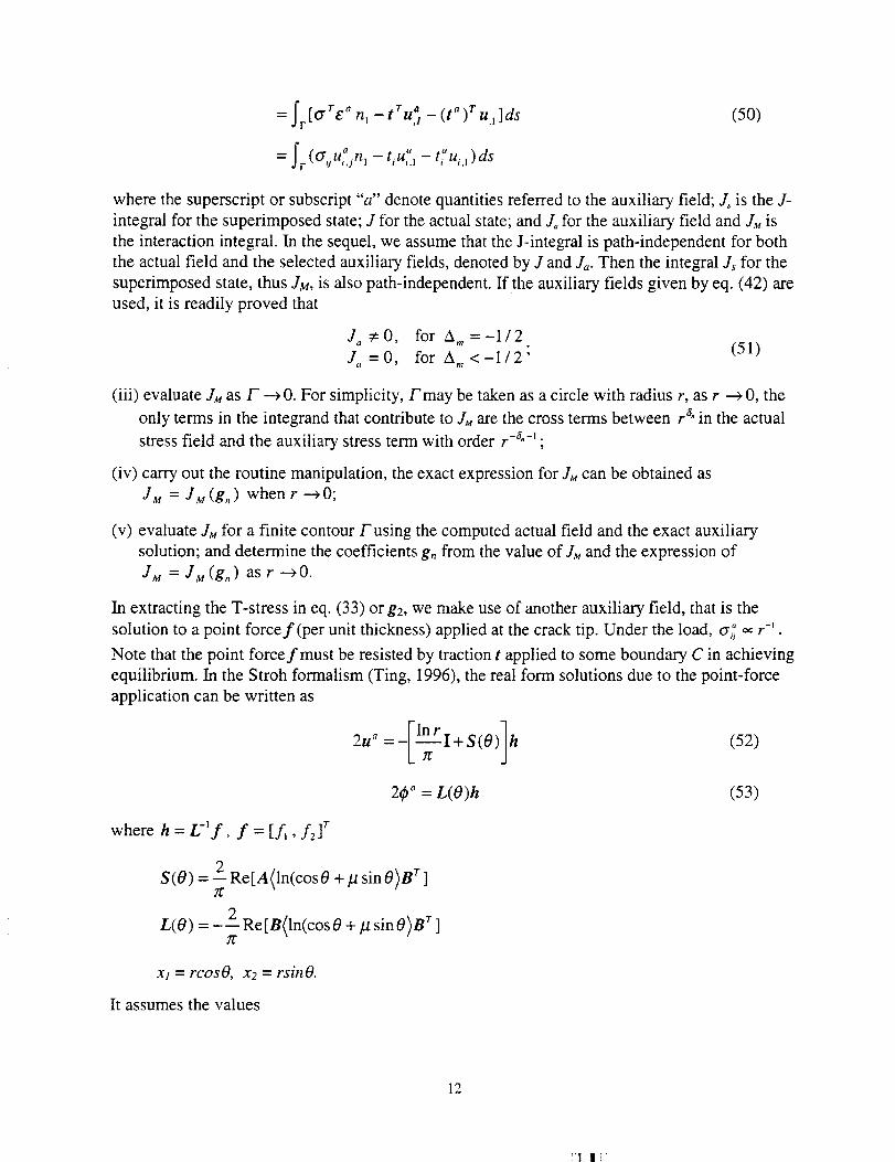
ftru a (t _ )r= Jr [O'vg_ ni - ,i - u,1]ds
= (_su_4n, - t,u,., - ti ui, 1)dsF
(50)
where the superscript or subscript "a" denote quantities referred to the auxiliary field; J_ is the J-
integral for the superimposed state; J for the actual state; and Jo for the auxiliary field and JM is
the interaction integral. In the sequel, we assume that the J-integral is path-independent for both
the actual field and the selected auxiliary fields, denoted by J and J,_. Then the integral ,Is for the
superimposed state, thus JM, is also path-independent. If the auxiliary fields given by eq. (42) are
used, it is readily proved that
J. s0, for A =-1/2
J.=0, for A <-1/2; (51)
(iii) evaluate armas F --)0. For simplicity, Fmay be taken as a circle with radius r, as r --) 0, the
only terms in the integrand that contribute to JM are the cross terms between r a"in the actual
stress field and the auxiliary stress term with order r-a°-_ ;
(iv) carry out the routine manipulation, the exact expression for JM can be obtained as
JM = JM (g,) when r --* 0;
(v) evaluate JM for a finite contour F using the computed actual field and the exact auxiliary
solution; and determine the coefficients g,, from the value of JM and the expression of
JM = JM (g,) as r --_ 0.
In extracting the T-stress in eq. (33) org2, we make use of another auxiliary field, that is the
solution to a point forcer (per unit thickness) applied at the crack tip. Under the load, tyi_ _ r-'.
Note that the point forcefmust be resisted by traction t applied to some boundary C in achieving
equilibrium. In the Stroh formalism (Ting, 1996), the real form solutions due to the point-force
application can be written as
2u_=-[l_---LrI+S(O)lh (52)
2_p'_= L(O)h (53)
where h = L-'f, f = [f_, f21 r
S(O) = 2 Re[A(ln(cos0 +/.t sin 0)B r ]
L(O) = - 2 Re[B(ln(cos 0 + # sin O)B r ]
xj - rcosO, x2 - rsinO.
It assumes the values
12
!'1 111
ln(cos0+p_sin0)=f 0 0=0
L+i_z 0 =+_z
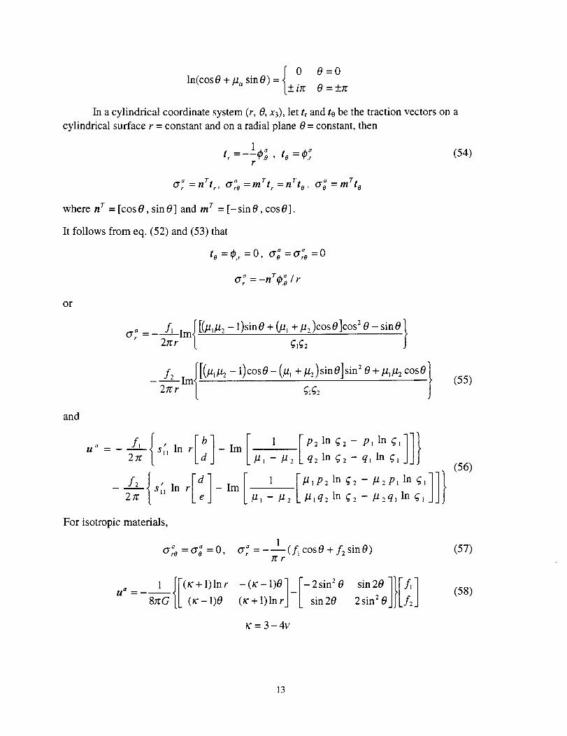
In a cylindrical coordinate system (r, 0, x3), let tr and te be the traction vectors on a
cylindrical surface r = constant and on a radial plane 0 = constant, then
tr =--O.0, to :4) rr
(54)
(/ t'/
Ct_ =nrt , tyro =mrtr=nrto ' (yo =mrto
where n r = [cosO, sin 0] and m r = [-sin 0, cosO].
It follows from eq. (52) and (53) that
to = (P,r= O, O"o = ff ,o = 0
a T a¢7_ = -n 0,o / r
or
_ fJ im_[_,l-t2-1)sinO+(u,+lz,_)cosO]cosZO-sinO}0"_= 2lrr { Cjj_2
and
f2
2_r-_Im{ [(/'t_l't2-- 1)c°sO- (/'/_ + ]'/2)sinO]sin2q_g20 + ]'/J]'/2cosO}(55)
(
u _ fl t '2re s_j Ink
f2 { ,2_z s_l In
For isotropic materials,
q2 In g2 -- ql In gl
Plq21n q2- P2qlln ql
(56)
O'ro = O'g = 0,1
_ = -_(f_ cos0 + A sin0)_r
(57)
1
8_G (g + 1)In rk (_c - 1)0
- (K- - 1)0 ]
(x" + 1) In rJ -
- 2 sin2 0
sin 20(58)
_'= 3-4v
13
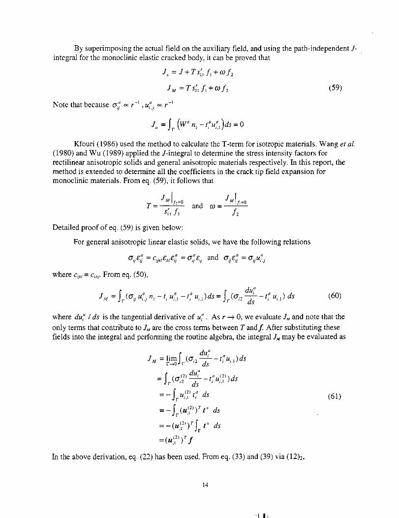
By superimposing the actual field on the auxiliary field, and using the path-independent J-
integral for the monoclinic elastic cracked body, it can be proved that
I
Js -- J+ Tslj fl +o9f2
JM = Ts_, f_ +o9 f2 (59)
Note that because at: _ r -_ , ui.jo_ r-I
t" a )ds 0J, = fr (Wanl - , u,., =
Kfouri (1986) used the method to calculate the T-term for isotropic materials. Wang et al.
(1980) and Wu (1989) applied the J-integral to determine the stress intensity factors for
rectilinear anisotropic solids and general anisotropic materials respectively. In this report, the
method is extended to determine all the coefficients in the crack tip field expansion for
monoclinic materials. From eq. (59), it follows that
Jg y.=0 JM y_=0T-- and o9-
s,, f, f2
Detailed proof of eq. (59) is given below:
For general anisotropic linear elastic solids, we have the following relations
a a _ Q_ a aa_jei} = cok,e,,ei_ a,i ij and aijg _ = _7ijui4
where cij_,= c_,i_.From eq. (50),
Jg=_r (°'ouT.jn'-t'uT.'-t;u_.')ds=f r (°'i2du;d--'-_-- t_" ui., ) ds (60)
where du{' / ds is the tangential derivative of u;. As r --_ 0, we evaluate armand note that the
only terms that contribute to Jg are the cross terms between T andf After substituting these
fields into the integral and performing the routine algebra, the integral J_ may be evaluated as
Jg = limf (o'_2 du7 "r-_0 or _ - ti ui,I ) ds
f ._(2) du7 __ (2)= tun ---_iui.l)dsr ds
=_ f U(2) aJr i.l ti ds (61)
f (" (2)'rt" ds=-Jr u't )
=-(ul2))rf t" ds,1 r
,t f
In the above derivation, eq. (22) has been used. From eq. (33) and (39) via (12)2,
14
!_IIf
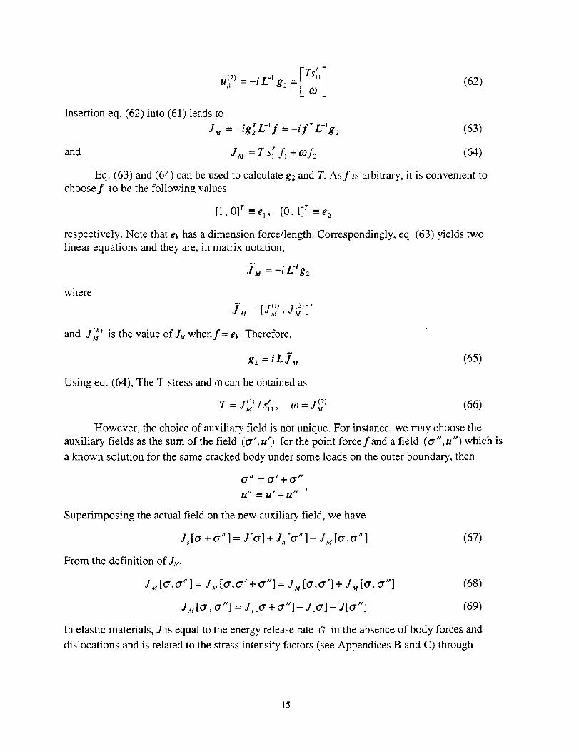
u (2) = -i L -I g2 = 1,I
Insertion eq. (62) into (61) leads to
JM =-igr L-_ f =-i fr L-l g2
and
(62)
(63)
JM = T s_, f, + cof2 (64)
Eq. (63) and (64) can be used to calculate g2 and T. Asfis arbitrary, it is convenient to
choosef to be the following values
[1,0] r-e,, [0,1] r-e 2
respectively. Note that ek has a dimension force/length. Correspondingly, eq. (63) yields two
linear equations and they are, in matrix notation,
]M = -i L'I g=
where
JM [(1) 1(2) IT= [_M ' _M
and r _k) is the value of JM when f= ek. Therefore,_M
g2 = i L ]M (65)
Using eq. (64), The T-stress and co can be obtained as
T=l(1)/s_-M , 0")= 1(2)--M (66)
However, the choice of auxiliary field is not unique. For instance, we may choose the
auxiliary fields as the sum of the field (a',u') for the point forcefand a field (a",u") which is
a known solution for the same cracked body under some loads on the outer boundary, then
0 "a = 0" + 0""
U a = U'+U t'
Superimposing the actual field on the new auxiliary field, we have
J,[o" + a a ] = J[o'] + J_ [o'" ] + Ju[a,a _ ] (67)
From the definition of JM,
JM[a,a _ ] = JM[a,a'+a"] = JM [O',O"] + JM[a, O'"] (68)
JM [a, a"] = J,[a + a"]- J[a] - J[cr"] (69)
In elastic materials, J is equal to the energy release rate G in the absence of body forces and
dislocations and is related to the stress intensity factors (see Appendices B and C) through
15
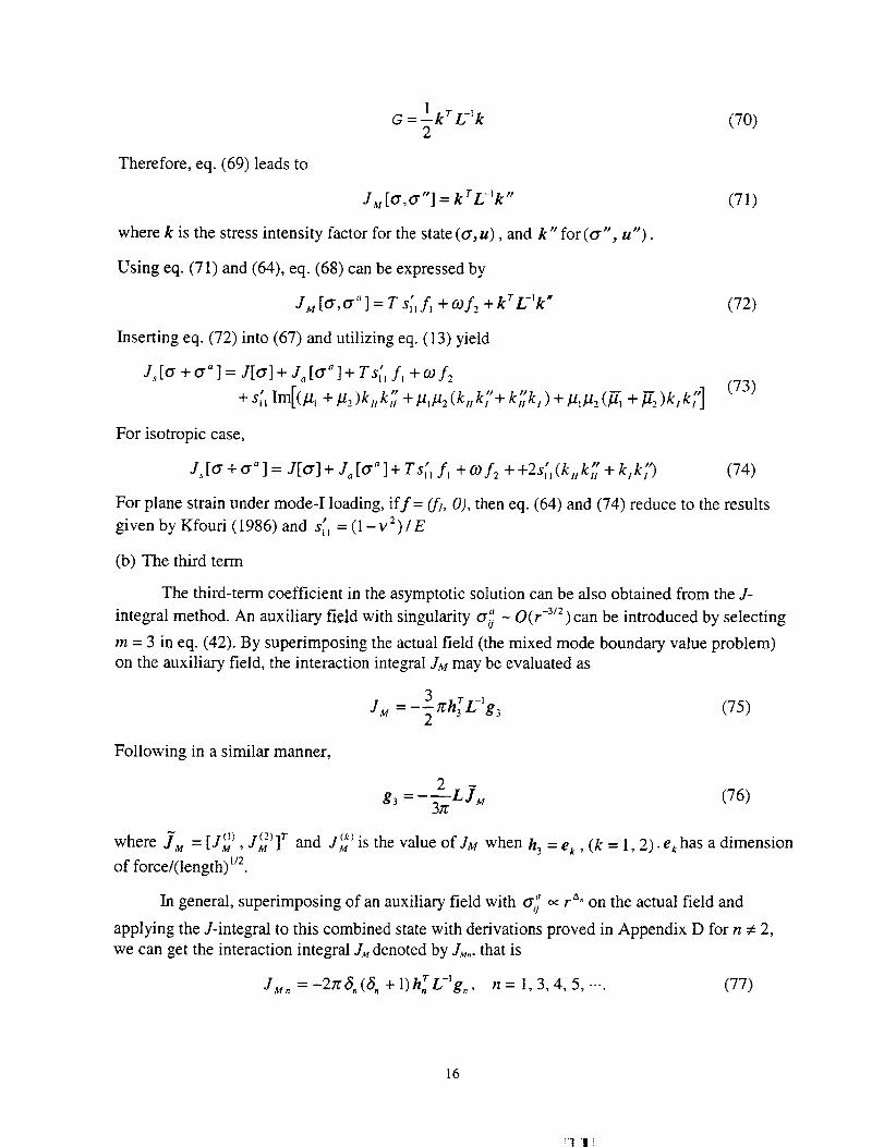
Therefore, eq. (69) leads to
G = 1 kr L-lk (70)2
JM [O',O'"] = krL-_k " (71)
where k is the stress intensity factor for the state (or, u), and k" for (or", u").
Using eq. (71) and (64), eq. (68) can be expressed by
JM [O',o'"] = Ts_f, + c.of2 +krL-_k" (72)
Inserting eq. (72) into (67) and utilizing eq. (13) yield
J,[ff + o'"] = J[o'] + J,,[o'"] + TS_l f_ +oof,_
+ s;_ Im[(.u_ + ].12)kakt7 + ].l,].12(kttk'/+ k;_k,)+/.tl/.t2 (_ + ]12)k,k;'] (73)
For isotropic case,
PP b'
J, [O"+ O'" ] = J[o'] + Ja [O'a ] + T s_, f, + co f2 + +2s_, (k, k H + k, k,') (74)
For plane strain under mode-I loading, if f= (f_, 0), then eq. (64) and (74) reduce to the resultsP
given by Kfouri (1986) and s,_ = (1 -v2)/E
(b) The third term
The third-term coefficient in the asymptotic solution can be also obtained from the J-
integral method. An auxiliary field with singularity o'_ - O(r -3_2) can be introduced by seIecting
m = 3 in eq. (42). By superimposing the actual field (the mixed mode boundary value problem)
on the auxiliary field, the interaction integral JM may be evaluated as
JM = _3 n'h r L-'g3 (75)2
Following in a similar manner,
(76)
where .IM [Jt_ ) 1 _z>lr and ,_k_.= , _M , a M is the value of JM when h 3 = e k , (k = 1,2). ek has a dimension
of force/(length) m
In general, superimposing of an auxiliary field with o'_ _ r"" on the actual field and
applying the J-integral to this combined state with derivations proved in Appendix D for n :/: 2,
we can get the interaction integral JM denoted by J.,,., that is
= 1-h r--IJM, -27r6,(_,+ ) ,,L g,, n=1,3,4,5,-.- (77)
16
!:IIf
Then
where
L]M.
= _- 2z_-+ 1) '
[ 2z a_ (a_ +1)'
n= 1,3,5,...
n=4,6,8,.--
(78)
Mn -- [I(1) I(2) 1T
lCk)and _M. is the value of J,.,. when
{ e_., n=1,3,5,...h, = iek , n=4,6,8,-..
Here, ek possesses dimension force / (length)1-8.. For the first singular term, introducing stress
intensity factors, k = [k H , k, ] r = _/2 g, for the actual field and k _ = [k_], k_] r = _ 2 h I for
the auxiliary field, JM, and k can be rewritten from eq. (77), (78) as
JM1 =(k_) r L-l k
k = LjMI (79)
where 'IM_ = rim l (2)1r and 1 (_) is the value of JM1 when k"I-_M1 _ _M1 J _M1 = ek •
Betti's Reciprocal Theorem
(a) T-stress Term
For a linear elastic plane problem, Betti's reciprocal theorem can be stated as
Ic(t . u_ - t" . u)ds = O (80)
where C is an any closed contour enclosing a simple connected region in the elastic body; u is the
displacement vector and t the traction on C corresponding to the solution of any particular elastic
boundary value problem for the elastic body; u" and t" are corresponding quantities of the
solution of any other problem for the body. Considering a crack in an anisotropic linear elastic
material, and suppose the crack surfaces are free of tractions for both elastic states. If the closed
contour C encloses the crack tip and extends along the crack surfaces, then it can be shown that
the integral
l = fr(t.u" -t".u)ds (81)
is path independent where Fis an any path which starts from the lower crack face and ends on
the upper. Let (t, u) be an actual state for the crack under consideration, then eq. (81) provides
17
sufficient informationfor determiningtheamplitudefor eachtermin theasymptoticcrack-tipfields if properauxiliarysolutions(ta, u a) are provided. In this section the Betti's reciprocal work
contour integral is used for computing stress intensity factors, T-stress and other higher-order
coefficients for monoclinic materials. The procedure can be evaluated from the analysis asfollows.
For determining the coefficients g, of the term r e" (S, > -1/2) in the actual crack tip stress
field, an auxiliary (pseudo) field with G_ o, r -a.-2 or u", _ r -6"-1 can be chosen. As r --_ 0, take a
F as a circle around the crack tip and evaluate integral I. When r --, 0, the only product between
g° and the auxiliary terms in the integrand given above can contribute to the integral I. Therefore,
the expression for I = l(g,) can be obtained as r _ 0. The value of ! for a finite contour Fshown
in Fig. 2 is available from the numerical solutions for t and u of the boundary value problems and
the exact auxiliary solution. The g, can be computed from the expression for I = I(g,) and thevalue of I.
To determine the T-stress org2 for the crack-tip field from eq. (34), the auxiliary elastica --')
field with stress singularity _Yu _ r " as r _ 0 is used and can be obtained from the eq. (42) by
choosing m = 4, that is, in Stroh formalism,
(82)
The moment about x3-axis applied at the crack tip, using eq. (23) and (82), is given by
M = -2/1: i ha,
When Fshrinks to the crack tip, it is clear that only those parts of the integrand in eq. (81) which
behaves like O(1/r) as r --_ 0 can contribute this portion of the integral. Substituting these fields
of the two states into eq. (81), performing the integration for the circle surrounding the crack tip
and evaluating the results in the limit of vanishing radius, the results may be derived, and
I lim[(tu" ta.u)ds -2_ r -_= " -- = h 4 E g2r-*0 dF
(83)
g2 = t-L- L I" (84)2re
where T = [I (" , I _2)] and I (k) is the value of/when h 4 = ie_, (k= 1, 2). (Dimension ofek is
force).
From eq. (13), (41), and (84),
1(1) /(2),, co=-- (85)
T - 2re s_ 2re
For isotropic materials, the auxiliary displacement vector and stress functions can be modified as
18
_i1l i
_, = si_O_I1 +cos20 sin20 1 im[h4 ]sin 20 1 - cos 20.](86)
rl_ 1 1122c°s30 c°sOor,_"2[ = 2 sin 30 sin 0
rye'2J -sin40
- sin 40
2(cos 20 - 1) sin 20
- 2 sin 30 sin 0
Im[h4] (87)
Eu;l:+E -+l co O+2 i 20 inO-,-u_J (to- 1)sin0 - cos20 sin0 - (x" + 1) cos0 - 2sin 20 sin 0
(88)
Then the path-independent integral I has the same form as eq. (83). Eqs. (84) and (85) are stillvalid.
(b) The Third Term
The coefficients of the third term in the eigenfunction expansion of the stress field can also
be obtained using Betti's theorem. Selecting m = 5 in eq. (42), an auxiliary field with stress
singularity rL_ - r -5/2 desired for this purpose can be obtained. Applying the Betti theorem of
reciprocity to the actual field and the auxiliary field and evaluating the integral I as F _ 0 near
the crack tip, we obtain
I =-31r h-_L-_g3 (89)
Eqs. (89) will be used to calculate gs for mixed-mode problem when the two proper auxiliary
field solutions are provided, g3 can be expressed in the form
g3 = _._1_1 L [ (90)37r
Applying Betti's reciprocal theorem to the actual fields and auxiliary fields with
o'_ja_ ra,.:, the path independent I denoted by/..,, can be evaluated by
I+ z =-2_ (S, + 1) hi,_ L -_ g, (91)
It follows from eq. (91)
gtl
L/_÷2n=1,3,5,.--
2zr(3, + 1)'
iLl,+2n=2,4,6,.-.
2;,r(3, + 1)'
(92)
where
, ITI j = t I_ '> I_ 2'
and lJ k) is the value of/; when
19
=f e k, n=1,3,5,--.h,
ie k, n=2,4,6,-..
Here, ek possesses dimension force x (length) _". The detailed proof is shown in Appendix E.
For the first singular term from eq. (91) and (92), I_ and k can be written as
13 =-re h_L-lgl =-_--_ h_L-Z k (93)
1k = -_ L r 3 (94)
_27r
Acknowledgments
The authors wish to acknowledge the financial support provided by NASA Grant 98-0548
from NASA Langley Research Center under Advanced Composite Technology Program. The
helpful discussions with the contract monitor, C. C. Poe, Jr., are also acknowledged.
References
1. D. An, "Weight Function Theory for a Rectilinear Anisotropic Body", International Journal
of Fracture, Vol. 34, pp. 85-109, 1987.
2. B. Cotterell, "Notes on the Paths and Stability of Cracks", International Journal of Fracture,
Vol. 2, pp. 526-533, 1966.
3. B. Cotterell and J. R. Rice, "Slightly Curved or Kinked Cracks", International Journal of
Fracture, Vol. 16, No. 2, pp. 155-169, 1980.
4. H. Gao and C. H. Chiu, "Slightly Curved or Kinked Cracks in Anisotropic Elastic Solids",
International Journal of Solicls and Structures, Vol. 29, No. 8, pp. 947-972, 1992.
5. C.C. Hong, and M. Stem, "The Computation of Stress Intensity Factors in Dissimilar
Materials", Journal of Elasticity, Vol. 8, No. 1, pp. 21-34, 1978.
6. G.R. Irwin, "Analysis of Stresses and Strains near the End of Crack Traversing a Plate",
ASME, Journal of Applied Mechanics, VoI. 24, pp. 361-364, 1957.
7. G.A. Kardomateas, R. L. Carlson, A. H. Soediono and D. P. Schrage, "Near Tip Stress and
Strain Fields for Short Elastic Cracks", International Journal of Fracture, Vol. 62, pp. 219-
232, 1993.
8. A.P. Kfouri, "Some Evaluations of the Elastic T-term using Eshelby's Method",
International Journal of Fracture, Vol. 30, pp. 301-315, 1986.
9. J.K. Knowles and E. Sternberg, "On a Class of Conservation Laws in Linearized and Finite
Elastostatics", Archive for Rational Mechanics and Analysis, Vol. 44, pp. 187-211, -1972.l
2O
_1 i]_
10. S. G. Larsson and A. J. Carlsson, "Influence of Non-Singular Stress Terms and Specimen
Geometry on Small-Scale Yielding at Crack Tips in Elastic-Plastic Materials", Journal of
Mechanics Physics and Solids, Vol. 21, pp. 263-277, 1973.
11. P. S. Leevers and J. C. Radon, "Inherent Stress Biaxiality in Various Fracture Specimen
Geometries", International Journal of Fracture, Vol. 19, pp. 311-325, 1982.
12. S. G. Lekhnitskii, Theory of an Anisotropic Elastic Body, Holden-Day, San Francisco, 1963.
13. J. R. Rice, "Limitations to the Small-Scale Yielding Approximation for Crack-Tip
Plasticity", ", Journal of Mechanics Physics and Solids, Vol. 22, pp. 17-26, 1974.
14. T. L. Sham, "The Theory of Higher Order Weight Functions for Linear Elastic Plane
Problems", International Journal of Solids and Structures, Vol. 25, No. 4, pp. 357-380, 1989.
15. T. L. Sham, "The Determination of the Elastic T-term using Higher Order Weight
Functions", International Journal of Fracture, Vol. 48, pp. 81-102, 1991.
16. G. C. Sih, P. C. Paris, and G. R. Irwin, "On Cracks in Rectilinearly Anisotropic Bodies",
International Journal of Fracture, Vol. 1, pp. 189-203, 1965.
17. G. B. Sinclair, M. Okajima, and J. H. Griffin, "Path-Independent Integrals for Computing
Stress Intensity Factors at Sharp Notches in Elastic Plates", International Journal for
Numerical Methods in Engineering, Vol. 20, pp. 999-1008, 1984.
18. M. Soni and M. Stem, "On the Computation of Stress Intensity Factors in Fiber Composite
Media Using a Contour Integral Method, International Journal of Fracture, Vol. 12, No. 3,
pp. 331-344, 1976.
19. M. Stern, E. B. Becker, and R. S. Dunham, "A Contour Integral Computation of Mixed-
Mode Stress Intensity Factors", International Journal of Fracture, Vol. 12, No. 3, pp. 359-
368, 1976.
20. T. C. T, Ting, Anisotropic Elasticity: Theory and Applications, Oxford University Press,
Oxford, 1996.
21. S. S. Wang, J. F. Yau, and H. T. Corten, "A Mixed-Mode Crack Analysis of Rectilinear
Anisotropic Solids using Conservation Laws of Elasticity", International Journal of
Fracture, Vol. 16, No. 3, pp. 247-259, 1980.
22. K. C. Wu, "Representation of Stress Intensity Factors by Path-Independent Integrals", ASME,
Journal of Applied Mechanics, Vol. 56, pp. 780-785, 1989.
21
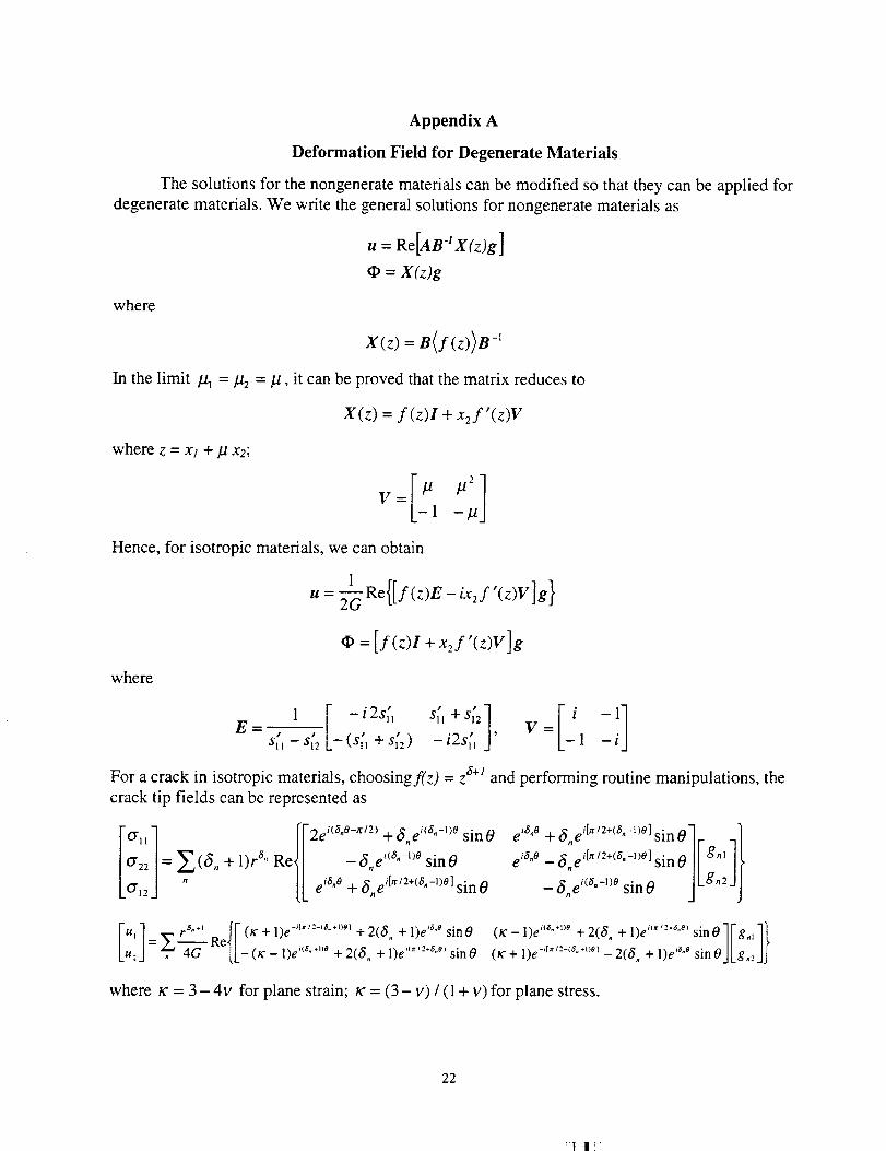
Appendix A
Deformation Field for Degenerate Materials
The solutions for the nongenerate materials can be modified so that they can be applied for
degenerate materials. We write the general solutions for nongenerate materials as
where
u : Re[AB" X(z)g]
= X(z)g
X(z)=B(f(z))B -_
In the limit /11 =/12 = p, it can be proved that the matrix reduces to
where z = x_ + I.t x2;
X(z) = f (z)I + x2f'(z)V
v:[:,:;,]Hence, for isotropic materials, we can obtain
u : _G Re{[ f(z)E- ix2f'(z)V ]g}
+.2S'(z)v]gwhere
1 -t2s_ s_ +S_zE= , , , . , V=
" - - t2s_s_ sl2 -(sll +sl2) ' 1
For a crack in isotropic materials, choosingf(z) = z a+l and performing routine manipulations, the
e i6"° -- _5,e i['_/2+(_"-_)°]sin g"_
,. ,(_.-_)o JLg,2JJ-o,e sin0
crack tip fields can be represented as
cT_,] [V2ei<_.e-"2> +_5,,e"'.-_)° sinO
o,,/: + l),'_" ReJ/ -_,,e i'8"-''° sinO
0"123 [k ei6"O + _5"e+"2+('s"-l)°] sin 0
[u,] = x-, --r_"+' _Kef/fF(tc+l)e-_t''-"*')'l+2(6.+l)e''"',.., ,.... sin0 (K"- l)e"'"*')' + 2(6 + 1)e ""'''"') sin01Fg., ll(8 )0 it# 6 e)
u: . 4G LL-(_:-I)e +2(S.+l)e sin0 (r+l)e-'r""-'_.")_'-2(,_+1)e'_.,"sinOJkg.:_lj
where _ = 3 - 4v for plane strain; _ = (3 - v) / (1 + v) for plane stress.
22
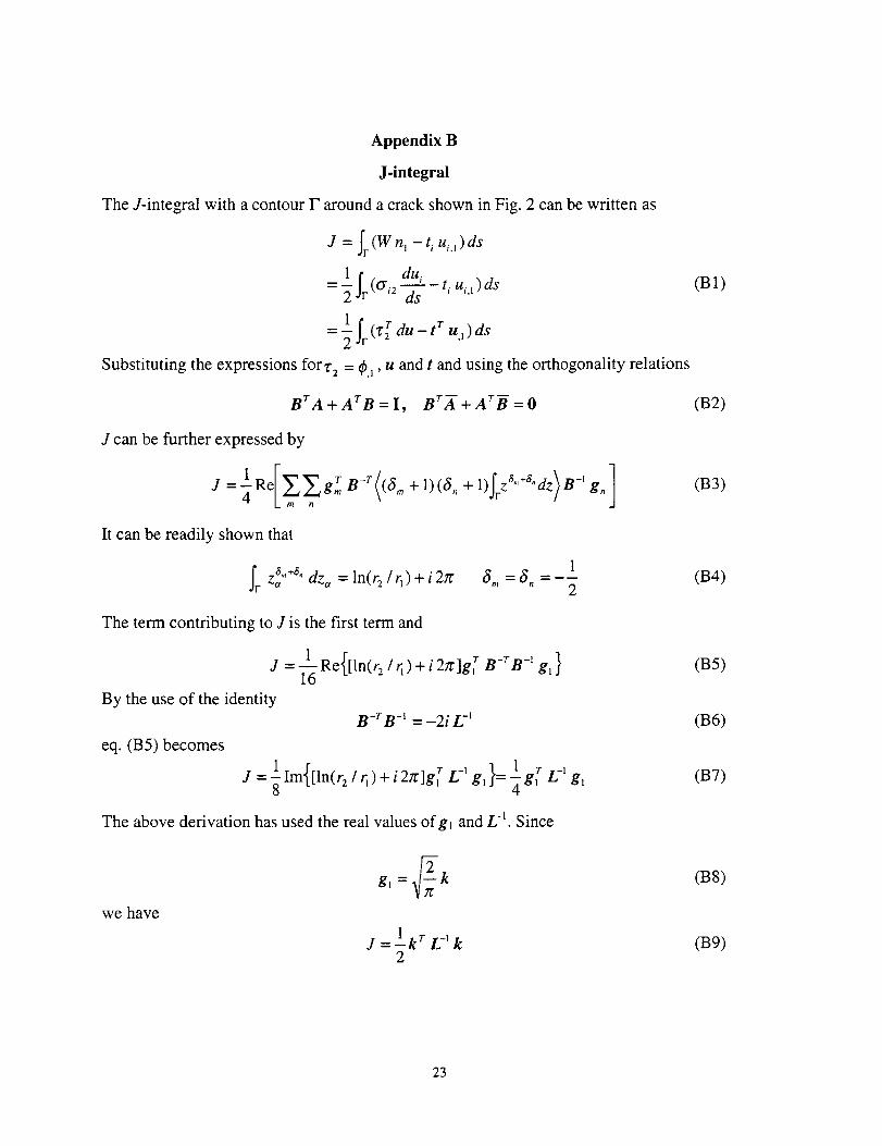
Appendix B
J-integral
The J-integral with a contour F around a crack shown in Fig. 2 can be written as
J = Ir(W n I - t i ui, 1)ds
= llr (ty n dui - t, u,,,)ds
1 r t r=-SSr du- u,)ds
(B1)
Substituting the expressions for't- 2 = _,l, u and t and using the orthogonality relations
BrA+ArB=I, BrA +ArB -=0 (B2)
J can be further expressed by
I ReI_grB-T((S., + 1)(S,, +l)SrZa'+"dz)B-'g. 7 (B3)
15,,, = S,_ = -- (B4)
2
It can be readily shown that
Sr z_''+e" dz= = ln(r2 / rx) + i 27r
The term contributing to J is the first term and
J = 1Re{[ln(r:/r_)+i2rglg r B-rB -' g,}16
By the use of the identity
B-r B -' = -2i 12 t
1 1.71j=llm{[ln(r21r_)+i2lr]gr L-' g,}=Tg r g,8
eq. (B5) becomes
The above derivation has used the real values ofgi and L q. Since
gl =_f_k
J = Ikr L -l k2
we have
(B5)
(B6)
(B7)
(B8)
(B9)
23
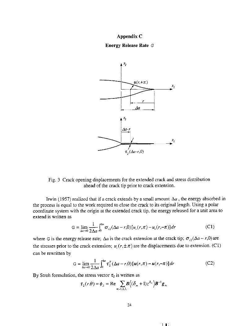
Appendix C
Energy Release Rate G
x2
xl
AY_
/
"C2 (Aa-r,O)
xli
Fig. 3 Crack opening displacements for the extended crack and stress distribution
ahead of the crack tip prior to crack extension.
Irwin (1957) realized that if a crack extends by a small amount Aa, the energy absorbed in
the process is equal to the work required to close the crack to its original length. Using a polar
coordinate system with the origin at the extended crack tip, the energy released for a unit area to
extend is written as
G lim 1 [_= o'_2(Aa - r,0) [u_(r, z) - u_ (r,-z)] dr (C 1)_,,+0 2Aa do
where G is the energy release rate; Aa is the crack extension at the crack tip; cri2 (Aa - r,0) are
the stresses prior to the crack extension; ui (r,___ to) are the displacements due to extension. (C 1)
can be rewritten by
G = _a-+olim2Aal i_, z_r(Aa-r,0)[u(r, rc)-u(r,-tc)]dr(C2)
By Stroh formulation, the stress vector z2 is written as
*'2(r.0)=_., =Re ZB((a., +l)za")n-'gmm=1,2,3,...
24
"1 1i
Along the crack plane, 0 = 0,
Za(Aa - r.0) = "_(S., + 1)(Aa - r)e"Re[g.,]m=1.2,3,-
= _(8 m + 1)(Aa- r)S"g.,m=1,3,5,...
= _ (j+2)(Aa - -j-l/2r) gzj.lj=O,l,2,-..
Note that gm is pure imaginary for m = 2, 4, 6, .... For the displacement vector u,
u=Re[ 2A(z_°+_)B -_ gn]n=1,2,3,...
At the crack flanks, 0 = +zr,
z = rcos(+:rr) = re +-ix, z 6"+1 = r 6"+_e +-i(6"+l)_r
Thus
Au = u( r, rc) - u( r,-rc )
= Re{ _.[A(r"+'e ''6"+°'_ -r'"+'e-'_"+')_)B-'g.]}n=1,2,3,...
= Re{ _rS"+'Zisin[(8. +l)JrlAB-'g.}n=1,2,3,---
= 2 _ r _"÷1 (--1) (n-l)/2 Re[U 1 - iSI-2 _]g.n =1.3.5,...
2 y__: 1x(n-l)/2L -I r 6"+t= _- ) g.
(C3)
(C4)
n=1,3,5,-..
= 2 _F_,(--1)lL-lg2l+lr t+1:2/=0,1,2,.-.
where the identity - AB -_ = SI2 _ + iI5 _has been used in deriving eq. (C4).
Substituting (C3), (C4) into (C2)
G=liml--_'Z2(J+2)(-1)'g2r÷,L-lg2,+lf_'r'(Aa-r):_A_- - dr (C5)ao-_o2Aa "7' i r
Introducing a nondimensional variable, x = r / Aa
G= _--,olim--_-iS" S' 2(J +1)(-1)'2Aa"7"7" 2 g2J+'L-' .i÷,+1 1 J_[_-xr g21+l (Aa) f0 xl(1 - x) dx
In the integrand, the linear term of Aa corresponds to the first term orj = l = 0
G = lira 1-_[g_L-lg_Aa_+o(Aa)]
_,_o 2Aa 2 (C6)
=--lkr L -_ k2
25
For the monoclinic solid with plane of symmetry at x3 = 0, L _ under in-plane deformation can be
expressed by
/2_ +/22 = a + ib, /2#12 = c + id
e = ad -bc = Im[/2,/22 (_ l + P2)]
-' s, [_ qF_27G--_ ,,[k2,k,] d eJLk, J
_ 1 s'--_ ,,[ek_ + 2dk,k z +bk__] (CS)
,{ - _ _ _}2 s_ Im[/2dz 2 (/2_ +/22)] k_" + 2 Im(/2_/22)k_k 2 + Im(/21 +/22)k
This expression can be reduced to orthotropic solids without cross term of kl and k2 in eq.
(C8). This special case has been formulated from Lekhnitskii formulation and the resuIts are
shown in eq. (26) of ref. (16) by G. C. Sih, P. C. Paris, and G. R. Irwin.
26
::!1 II:
Appendix D
Determining the Unknown Coefficients in the Crack Field Using the J-integral
The path-independent integral JM from eq. (60) is
du; tTu,,)ds (D1)
Let the actual and auxiliary crack fields
= B l (D2)
dO" = B(fa (z))B-'h (D3)
where
f, (z) = z a"+_, _, = (n - 2) / 2 , n = 1, 2, 3, ....
f" (z) = z _"+l A,, = -m / 2 m = 1, 3, 4, ..-
From the identity
1 1Re(C) Re(D) = = Re[(C + C ) D] = _- Re[C(D + D)]
Z Z(D4)
where C and D are complex matrices, we have
a_2 du_/ = du 7 Re[q_g.I ] = d(u a )r Re[O_ ]
= d [Re(AB-_ a ) r ] Re[_ ]
1
= -2 Re[(aB-_dO,, )r (0, + c.c.)]
(D5)
and
dO7t_Ui, t ds = -Re(--'-_s )ui, , ds
= _ Re(dOa )r Re[AB-'O,]
1Re[(dO a )r (AB-'O= -- .l + c.c.)]
2
(D6)
where c.c. denotes the complex conjugate of the preceding term, i.e.,
F + c.c.= F + F
Therefore
27
=-1 Re[ ._f2 r (hr B-r(df_) ArB{f_'}B-'g" +hrB-r{df_}ArB{-f'} _-'g--"
+ ]l--
iRe (hrB -r(df )(A rB+B A)(f_)B g_2 r
+hrB-r(df_)(ArU+ BrX)(f':)U-'g"- )]
Using the orthogonality relations in eq. (10) and (11),
ArB+BrA=I and ArB'+BrA -=0,
A, can be further rewritten as
(D7)
Ju=l-Re[_IrhrB-r(df" }(f.}' B-' g,,2 L.
(D8)
Defining
I *' a I 6 +A,_R,.. -- rf"(z_)df (z,_)=(a. +I)(A,,,+I) rZ_ dz,,
it is readily shown that
(a) n=m or S. +A., +1=0,
I dz,_ = _S m(S., + 1)[ln(rz / rl ) + i 2,r] ;Rm. = (S. + 1)(A m+ 1) r z_
(b) n:gm orS. +A., + 1:,: 0,
gmn m
(a. + 1)(2- m)
r/-m
{ [r_,-,.):2 _ q(.-m):2 ] cos(n - m)lr / 2 + i[r, ('-'_):2 + r__"-m):2 ] sin(n - m)a: t 2}
i,e°
(_1): (S. + 1)(2 - m) [r(._.,>: 2 _ r:._.,)/2 ]
-m
Rm" = i(-1): (an + i)(2 - m) [r}n_m)l 2 + rl(._m)/2 ]_--m
for n-m= 2j
for n-m=2j+l
Using R.. and the identity
B-r B-1 = _2i L-I
denoting J_uas JM.,, h as hm, eq. (D8) becomes
28
!:1 !11]:
1JM., = --Re R.,.h2 L n _1
1 = I R r -1- - Re _. : 2 "'h r "-_i- t) mL g_
=Im[R,.mhmLr -,g.,]+ _Im(R°,.)h_L-'g_ + _Im(Rm.h2L-'g.)n
n=m+2j,n_m n=m+2j+l
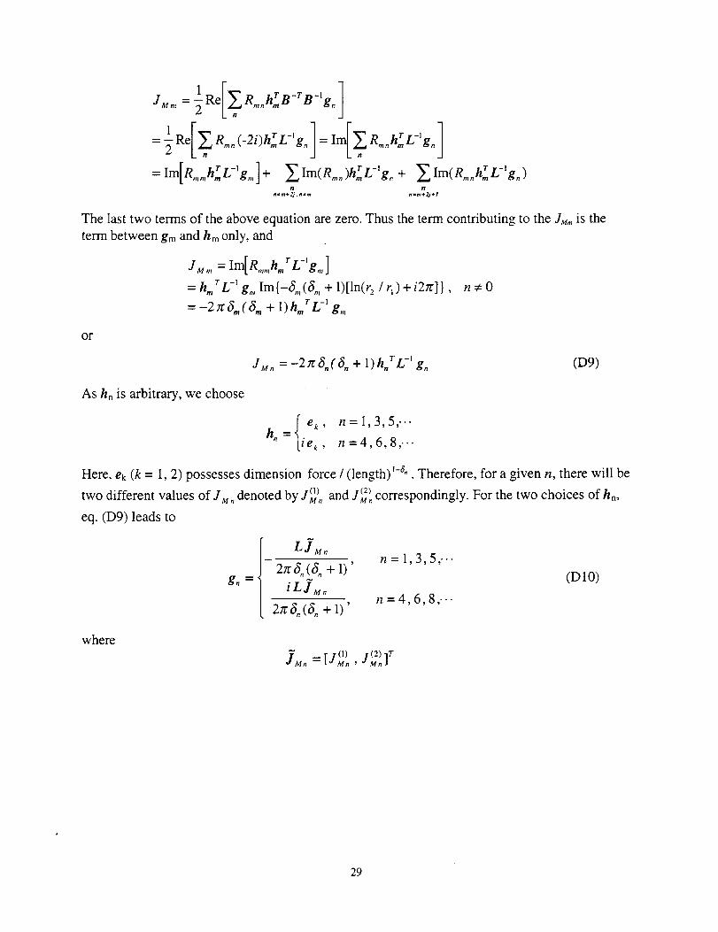
The last two terms of the above equation are zero. Thus the term contributing to the JM,.. is the
term between gm and hm only, and
J M m = Im[ Rmmhmr L-_ g., ]
=hm Lr -1gin Im{-S.,(8., + I)[ln(r 2/q)+i2zr]} , n:/:0
=--2_l_m(am + 1)h,. rL-' gm
or
JM. = -2rc(5.((5. + 1)h rL -' g. (D9)
As hn is arbitrary, we choose
{e_, n = 1,3,5,..-h.= iek, n=4,6,8,.--
Here. ek (k = 1, 2) possesses dimension force / (length) _-_" . Therefore, for a given n, there will be
two different values of JM. denoted by -M.1°)and J_). correspondingly. For the two choices of h..
eq. (D9) leads to
gn
LJM.n = 1,3,5,.-.
2n'S. (S +1)'
iL_M n (DIO)n =4,6,8,..-
2rc_. (_. + 1)'
where
I-1 (I) /(2) ]rJMn _ t_ Mn _ _ Mn
29
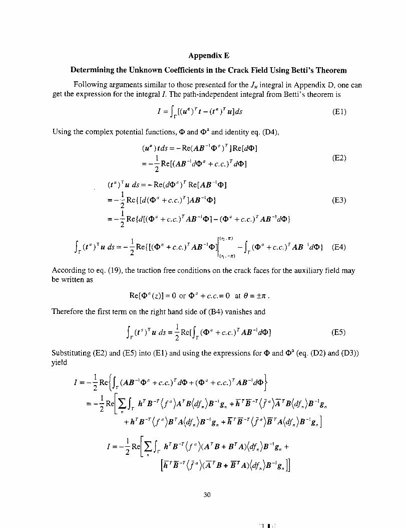
Appendix E
Determining the Unknown Coefficients in the Crack Field Using Betti's Theorem
Following arguments similar to those presented for the JM integral in Appendix D, one can
get the expression for the integral I. The path-independent integral from Betti's theorem is
I = j'r [(u" )rt - (t")r u]ds (El)
Using the complex potential functions, _ and (I)a and identity eq. (D4),
(u") tds = - Re(AB-I_" ) r ] Re[d_]
1= --Re[(AB-]ddp _ + c.c.)rd_]
2
(E2)
(t" )T U ds = - Re(dO" ) r Re[AB -1_]
I
= -_-Re{[d(_" + c.c.)r]AB-E_}
1= --- Re{d[(_ a + c.c.)rAB-_dp] _ (_ + c.c.)rAB-]d_}
2
(E3)
[(r2,_r)
fr <' -2 L,.-,o(t)Tu ds= 1Re{[(_" +c.c.)rAn-'_] -fr(O _ +c.c.)rAB-_dO} (E4)
According to eq. (19), the traction free conditions on the crack faces for the auxiliary field maybe written as
Re[_(z)]=0or_a+c.c.=0 at0=+rc.
Therefore the first term on the right hand side of (B4) vanishes and
fr (t_)T u ds: 1Re[Yr (_" + c.c.) r AB-iddp] (E5)
Substituting (E2) and (E5) into (El) and using the expressions for _ and _ (eq. (D2) and (D3))
yield
I=-2 Re{St (AB-'¢II" + C'c')T d_+ (¢II _ +c.c.)TAB-'d_}
-1Re/ZS h (f ) B(df.)B g.= rB-r , A r -I2 L.
+ h r B -T (f"}B TA(df. }B-lg. + _r_-r (f.}_rA(df_)B-]g. ]
I=-2 Re Sr hrB-r(f") (ATB+ BrA)(df") B-ig" +
[h-rB--r(/_)(A-rB + BrA)<df,,)B-'g,,]]
3O
_I I i
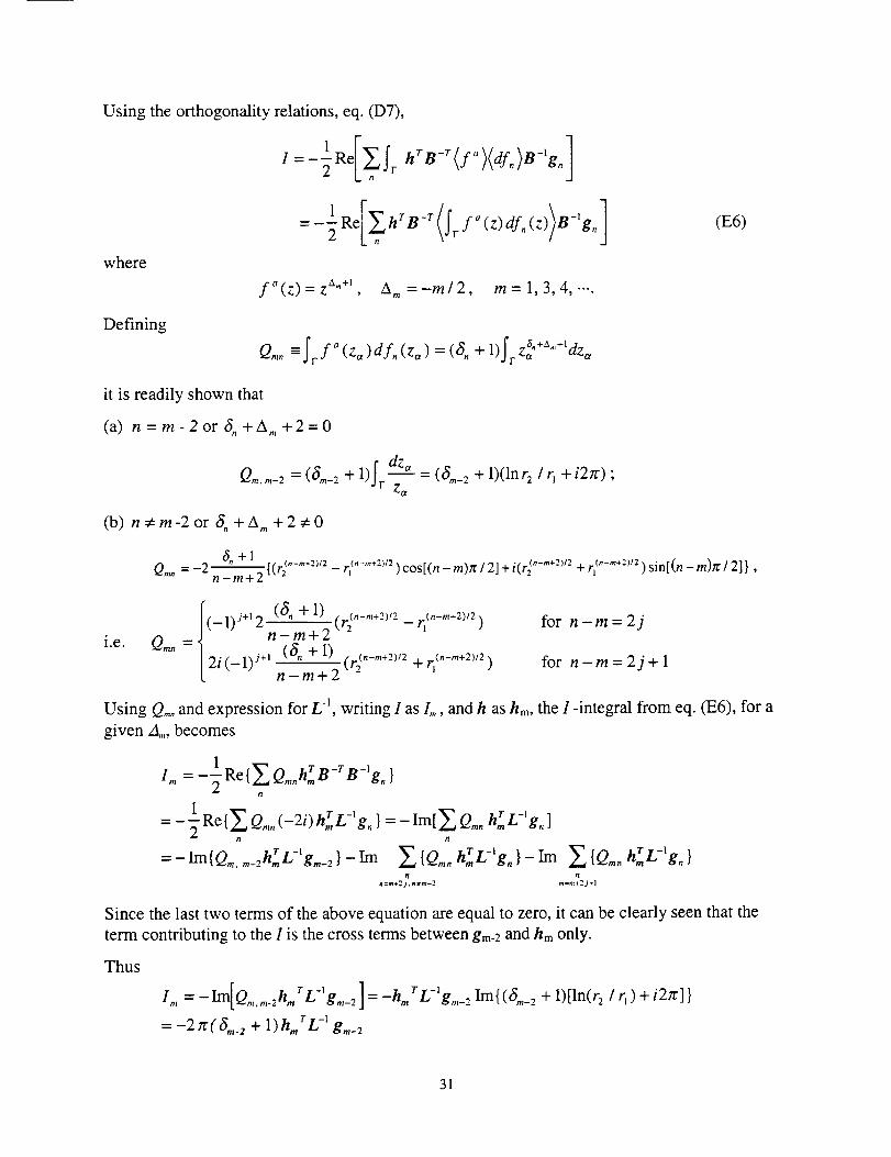
Using the orthogonality relations, eq. (D7),
where
Defining
_1 Re _., (f )(df.)B g. ]I= 2 [,_ fr hrB-r a -,
-1Re Y_,hrB-r " (z))B-'g.]= 2 [, (frf (z)df,,
fa(z)=z A"+l A,,,=-m/2 m = 1, 3.4, -..
Q.,. =fr.f,_(z_,)df,,(zo,)=(S,, +l)f v a.+a,,,+,-Za aza
it is readily shown that
(a) n=m-2or6_+A.,+2=0
Idz,_Q.,.m-2 = (6,.-2 + 1) r-_- = (S'_-2 + 1)(lnr2 ! q + i2_:) ;
(b) n_em-2 or _. +A.,+2_0
So+1Qm_=-2
n-m+2
i.e.
(E6)
[(r_ .... 21/2_ r( .... 2v2 ) cos[(n - m)rc / 2] + i(r(z.... 2_t2+ rl_.... 2)12) sin[(n - m)n: / 2] },
(_l)S+t (_.+1) (r_z._.,+2;Z_rlC._.,+z_lz)Q.,. = n -(6.m+ 2+1)
2i(_l)J ÷_ (r_("-re+z)/2+ r{.-,.+2)a)n-m+2 "
for n-m= 2j
for n-m= 2j + l
Using Qm° and expression for L -l, writing I as L, and h as hm, the I -integral from eq. (E6). for a
given Am. becomes
I,. =-lRetY__Q,..hrmB-r B-' g . }2
= _I Re{_ Q.,. (-2i) hrL -_g. } = -Ira[ E Q.,. h r L -lg.]2 n n
__ tT L-I=-Im{Q,. .... 2h,. LT-'gin-2} Im E{Qmnnrn gn}_i m ,_..,{Q,.. hrnLr-,gn}11 Vl
n=,n+2j,n*m-2 m=m+2j÷l
Since the last two terms of the above equation are equal to zero, it can be clearly seen that the
term contributing to the I is the cross terms between gm-2 and hm only.
Thus
Im[ r-, ] r-_I,,, = - Q ..... zh., L gin-2 = -h., L gin-" Im{ (6.,_ 2 + 1)[ln(r 2 / r1) + i2Jr] }
= -2rr(a..2 + 1)h,. rL< gin-2
31
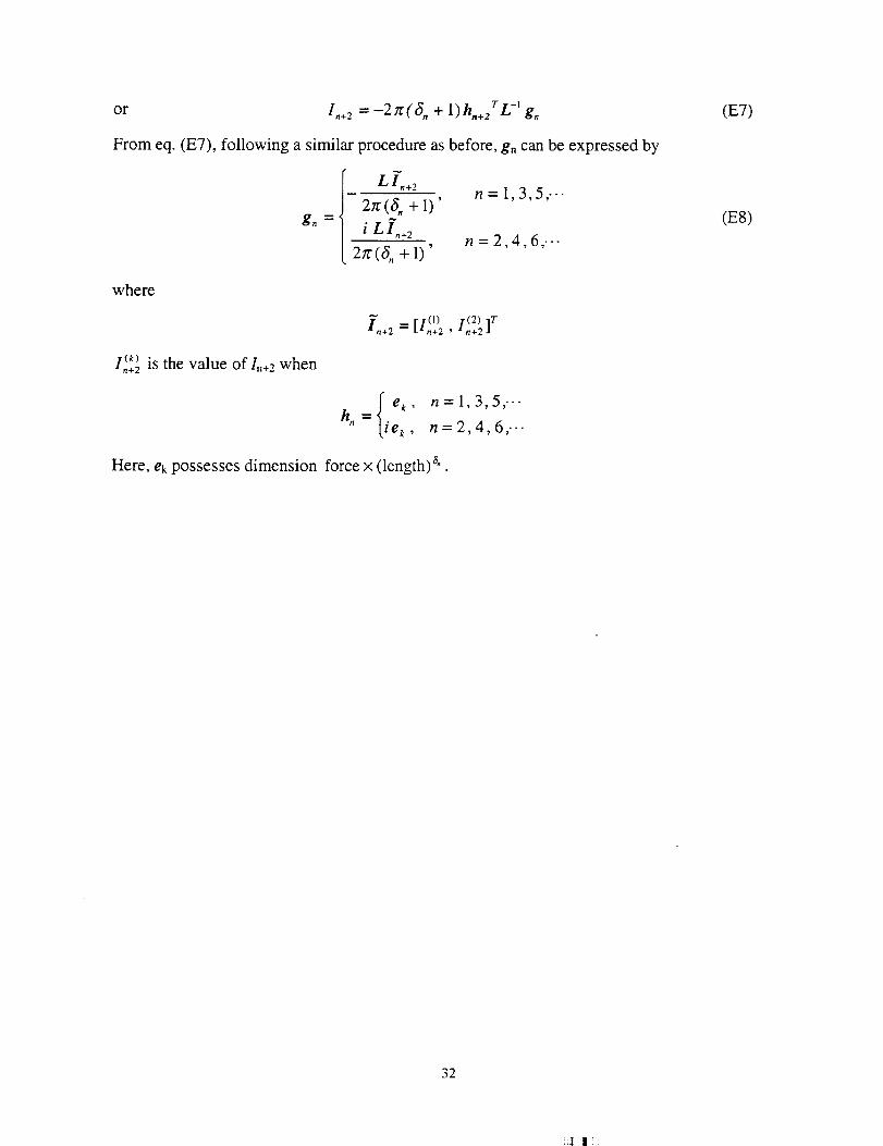
or I,+ 2 -2rr(S, + 1 r -_= )h,,.e L g. (E7)
From eq. (E7), following a similar procedure as before, gn can be expressed by
gn _--"
Li.÷2
2_(S. + 1)'
n = 1,3,5,.--
n = 2,4,6,..-
where
in+_ = [/(1) /(2) ]T_ I-*n+2 _ an+2
I (k_ is the value Of/n+, when.'l+2
=j e k, n=1,3,5,.-.h,,
ie k, n=2,4,6,--.
Here, ek possesses dimension force x (length) a" .
(E8)
32
i_| IIi
REPORT DOCUMENTATION PAGE Fo.. ApprovedOMB No, 07704-0188
Public reporting burden for this collection of information is estimated to average 1 hour per response, including the time for reviewing instructions, searching existing data sources,gathering and maintaining the data needed, and completing and reviewing the collection of information. Send comments regarding this burden estimate or any other aspect of thiscollection of information, including suggestions for reducing this burden, to Washington Headquarters Services, Directorate for Information Operations and Reports, 1215 JeffersonDavis Highway, Suite I204, Arlington, VA 22202-4302, and to the Office of Management and Budget, Paperwork Recluction Project (0704-0188), Washington, DC 20503.
1. AGENCY USE ONLY (Leave blank) 2. REPORT DATE 3. REPORT TYPE AND DATES COVERED
October 1998 Contractor Report4. TITLE AND SUBTITLE 5. FUNDING NUMBERS
Determination of Stress Coefficient Terms in Cracked Solids for Monoclinic
Materials with Plane Symmetry at x 3 = 0
6. AUTHOR(S)
F. G. Yuan
7. PERFORMING ORGANIZATION NAME(S) AND ADDRESS(ES)
Mars Mission Research Center
Department of Mechanical and Aerospace EngineeringNorth Carolina State UniversityRaleigh, NC 27695
9. SPONSORING/MONITORING AGENCY NAME(S) AND ADDRESS(ES)
National Aeronautics and Space AdministrationLangley Research CenterHampton, VA 23681-2199
11. SUPPLEMENTARY NOTES
Langley Technical Monitor: Clarence C. Poe, Jr.
WU 538-13-11-01
NAGI-1981
8. PERFORMING ORGANIZATION
REPORT NUMBER
10. SPONSORING/MONITORING
AGENCY REPORT NUMBER
NASA/CR- 1998-208729
12a. DISTRIBUTION/AVAILABILITY STATEMENT
Unclassified-Unlimited
Subject Category 26 Distribution: StandardAvailability: NASA CASI (301) 621-0390
12b. DISTRIBUTION CODE
13. ABSTRACT (Maximum 200 words)
Determination of all the coefficients in the crack tip field expansion for monoclinic materials under two-dimen-
sional deformation is presented in this report. For monoclinic materials with a plane of material symmetry at x 3 =0, the in-plane deformation is decoupled from the anti-plane deformation. In the case of in-plane deformation, uti-lizing conservation laws of elasticity and Betti's reciprocal theorem, together with selected auxiliary fields, T-stressand third-order stress coefficients near the crack tip are evaluated first from path-independent line integrals. Todetermine the T-stress terms using the J-integral and Betti's reciprocal work theorem, auxiliary fields under a con-centrated force and moment acting at the crack tip are used respectively. Through the use of Stroh formalism inanisotropic elasticity, analytical expressions for all the coefficients including the stress intensity factors are derivedin a compact form that has surprisingly simple structure in terms of the Barnett-Lothe tensors, L. The solutionforms for degenerated materials, orthotropic, and isotropic materials are presented.
14. SUBJECT TERMS
Anisotropic elasticity; Two-dimensional deformation; Stroh formulation; Stresscoefficient; T-stress; J-integral; Betti's reciprocal theorem
;17. SECURITY CLASSIFICATION
OF REPORT
Unclassified
18. SECURITY CLASSIFICATION
OF THIS PAGE
Unclassified
NSN 7540-01-280-5500
19. SECURITY CLASSIFICATION
OF ABSTRACT
Unclassified
15. NUMBER OF PAGES
3716. PRICE CODE
A03
20. LIMITATION
OF ABSTRACT
UL
Standard Form 298 (Rev. 2-89)Prescribed by ANSI Std. Z39-18298-102
_'1l]i


![€¦ · Web viewτ0 =shear stress at solid boundary[N/m2]Schuifspanningξ = (ksie)Loss coefficient [1]Verliescoëfficiëntµ =contraction coefficient[1]Contractiecoëfficiënt Fluid](https://img.pdfslide.us/doc/110x75/5e4816113c4afe0e0f6b2d91/web-view-0-shear-stress-at-solid-boundarynm2schuifspanning-ksieloss.jpg)