Embed Size (px)
Citation preview

1886
Abstract Stress intensity factors (SIF) are determined for an inclined and / or eccentric crack in a finite orthotropic lamina using the bounda-ry collocation method. The stress functions are defined such that they satisfy governing equations in the domain, the boundary condition on the crack surface and also the singularity at the crack tip. The unknown coefficients in the stress functions are deter-mined such that the boundary condition on the edges of lamina is satisfied. The analysis is also being carried out for isotropic mate-rial using finite element analysis software ANSYS for comparison of results. Also, comparison of results with existing solutions is found in good agreement. Keywords Stress intensity factors, orthotropic lamina, eccentric crack, boun-dary collocation.
Stress intensity factors for an incl ined and/or eccentric crack in a finite orthotropic lamina
NOTATION
a11,a12,a22,
a16,a26,a66
Elastic Constants for orthotropic lamina
σx,σy Stresses in x and y directions respec-tively
P Applied Stress in y-direction τxy Shear stress in x-y plane.
Q No. of collocation points on the edges of the lamina
ν12 Poisson’s Ratio
G12 Shear Modulus
KI, KII Mode I and Mode II Stress intensity Factors respectively
Shashikant Joshia
S. Manepati lb
a Mechanical Engineering Department, Institute of Technology, Nirma Univer-sity Ahmedabad. 382481 India. [email protected] b Mechanical Engineering Department, SGSITS Indore. India. [email protected]

1887 S. Joshi and S. Manepatil/ Stress intensity factors for an inclined and/or eccentric crack in a finite orthotropic lamina
Latin American Journal of Solids and Structures 11 (2014) 1886-1905
ex, ey Eccentricity of the crack in x and y directions respectively.
YI, YII Normalized Mode I and Mode II Stress intensity Factors respectively
Re Real part N,M No. of terms associated with the stress functions
α Angle of fibre orientation zk Complex coordinate, zk=x+sky.
εx, εy, γxy Longitudinal, transverse and shear strains
U(x,y) Airy’s stress function
Φ(z1), ψ(z2)
Stress Functions Ak, Bk, Unknown coefficients in the stress functions.
a Crack length θ Angle of the crack.
sk , k=1,2 Complex parameters of anisotropy k Biaxial loading factor
1 INTRODUCTION
The topic of crack problem in finite orthotropic lamina has received considerable attention as the applications of structures using the composite materials are increasing with every sunrise. The SIF of a finite lamina is different from that of infinite lamina according to the dimensions of lamina, crack length, crack angle, material properties and boundary conditions. Accurate determination of stress intensity factor of finite lamina is required for ensuring reliable design of the structures. Boundary collocation method has been proved to be an effective computational tool and has been successfully applied to variety of crack problems of isotropic materials (Chen and Chen, 1981; Newman, 1976; Ukadgaonkar and Murali, 1991; Wang et.al, 2003) and anisotropic materials (Wang and Chang, 1994; Woo and Samson, 1993). Various methods like modified mapping collocation method (Bowie and Freese, 1972), boundary integral equations (Tan and Gao, 1992) and singular integral equation formulation (Ryan and Mall, 1989) are successfully applied to solve the problems of finite orthotropic lamina / laminates containing edge / central crack. The finite element method for determination of stress intensity factors is not well suited for discontinuities that do not align with the element edges. In order to get rid of this, mixed mode stress intensity factors using element free Galerkin method (Ghorashi et.al, 2011). Further to this, enriched finite element method is employed (Ozkan et.al., 2010) for study of effect of anisotropy on stress intensity factors for a cracked compact tension specimen, edge specimen and a plate containing central inclined crack. Calculation of the SIF from full field displacement data and asymptotic expansion of the crack tip displacement field is one possibility. This approach requires use of X-ray diffraction and optical microscopy (Wang et.al., 2011). Conformal mapping is promising method for solution of various crack problems in anisotropic plates. It is used (Beam and Jang, 2011) for obtaining SIF of a crack emanating from a infinite wedge in anisotropic material under antiplane shear.

1888 S. Joshi and S. Manepatil/ Stress intensity factors for an inclined and/or eccentric crack in a finite orthotropic lamina
Latin American Journal of Solids and Structures 11 (2014) 1886-1905
In the present work, stress intensity factors are determined for an inclined crack in a finite or-thotropic lamina subjected to uniaxial / biaxial loading to study the effect of fibre angle, crack an-gle and biaxial loading factor. Also, effect of eccentricity in x direction and/or y direction is studied.
2 BASIC EQUATIONS
The generalized Hooke’s Law in plane stress for an orthotropic lamina can be expressed in the fol-lowing manner (Lekhnitskii, 1976).
ε!ε!τ!"
= a!! a!" a!"a!" a!! a!"a!" a!" a!!
σ!σ!τ!"
Representing σx, σy, τxy in terms of Airy’s stress function U(x, y)
σ! =∂!U∂y!
; σ! =∂!U∂x!
; τ!" =− ∂!U∂x ∂y
The compatibility condition is,
∂!ε!∂y!
+∂!ε!∂x!
=∂!γ!"∂x ∂y
By introducing Hooke’s law in terms of F(x,y) into the compatibility equation, we get following bi-harmonic equation
a!!∂!U∂x!
− 2a!"∂!U∂x! ∂y
+ 2a!" + a!!∂!U
∂x! ∂y!− 2a!"
∂!U∂y! ∂x
+ a!!∂!U∂y!
= 0
The Airy’s stress functions can be represented as
U x, y = 2Re U! z! + U! z! (5)
z! = x + s!y; z! = x + s!y U1 and U2 are analytic functions of complex variables z1 and z2 respectively. The complex parame-ters s1 and s2 are roots of characteristic equation
a!!s! − 2a!"s! + 2a!" + a!! s! − 2a!"s + a!! = 0
The stress components are represented in terms of stress functions,
σ! = 2Re Φ! z! + ψ! z!
(1) (1)
(2)
(3)
(4)
(6)

1889 S. Joshi and S. Manepatil/ Stress intensity factors for an inclined and/or eccentric crack in a finite orthotropic lamina
Latin American Journal of Solids and Structures 11 (2014) 1886-1905
σ! = 2Re s!!Φ! z! + s!!ψ! z! τ!" = −2Re s!Φ! z! + s!ψ! z!
where,Φ z! = U!! z! ,ψ z! = U!! z!
3 STRESS FUNCTIONS
Figure 1 shows various crack configurations considered in the present study. The coordinate system x1-o1-y1 is used for defining the various orientations. The principal axes of orthotropy are considered to be located at an angle α to the reference axis. The crack is inclined at an angle θ. The stress functions are defined with respect to x-o-y coordinate system and hence facilitating further deter-mination of stress intensity factors.
Figure 1: An inclined and / or eccentric crack in a finite orthotropic lamina.
A function F is introduced to define the functions Φ and ψ. The function F consists of
F = F! + F! (8)
The functions Φ and ψ consist of two parts viz.
Φ = Φ! + Φ! ψ = ψ! + ψ! (9)
(7)

1890 S. Joshi and S. Manepatil/ Stress intensity factors for an inclined and/or eccentric crack in a finite orthotropic lamina
Latin American Journal of Solids and Structures 11 (2014) 1886-1905
Relationship between Φ1, ψ1 and F1 is
Φ! z! = F! z! ψ! z! = −BF! z! + CF! z! (10)
The relationship between Φ2, ψ2 and F2 is,
Φ! z! = F! z! ψ! z! = −BF! z! + CF! z!
(11)
B =(s! − s!)(s! − s!)
; C =(s! − s!)(s! − s!)
In order to satisfy the stress singularity at the crack tips and ensuring stress free boundary con-dition on the crack surface, stress functions are defined as,
F! z = (z! − a!) A! z!!!!
!!!!
F! z = B! z!!!!
!!!!
Leading to,
Φ z! = (z!! − a!) A! z!!!!!
!!!!
+ B! z!!!!!
!!!!
ψ z! = C z!! − a! A! z!!!!!
!!!!
+ B! z!!!!!
!!!!
+ B B! z!!!! −!
!!!!
z!! − a! A! z!!!!!
!!!!
Ak and Bk are the complex coefficients to be determined such that boundary condition on the edges of lamina is satisfied. The stress components can be calculated as per equation 7. At a point on the lamina boundary, boundary condition can be represented as of two types
i) Stress boundary condition ii) Force boundary condition
Force boundary condition is expressed in terms of
f! + if! = 1 + is! Φ z! + 1 + is! ψ z! + 1 + is! Φ z! + 1 + is! ψ z! + c (13) The determination of constants in the stress functions and hence the stress functions will facili-tate the determination of stress intensity factors as,
(12)

1891 S. Joshi and S. Manepatil/ Stress intensity factors for an inclined and/or eccentric crack in a finite orthotropic lamina
Latin American Journal of Solids and Structures 11 (2014) 1886-1905
K!" = 2 2π(s! − s!)
s!lim!!→!
z! − a e!!!Φ!! z!
K!!" = 2 2π (s! − s!) lim!!→!z! − a e!!!Φ!
! z!
K!" = 2 2π(s! − s!)
s!lim!!→!!
z! + a e!!!Φ!! z!
K!!" = 2 2π (s! − s!) lim!!→!! z! + a e!!!Φ!! z! (14)
4 NUMERICAL RESULTS AND DISCUSSIONS
4.1 Solution Procedure
1. The coordinates of No. of collocation points Q are marked which along with the angle of the fibre orientation determine the z1 and z2.
2. At all collocation points, total error with respect to stresses (equation 7) and traction (equation. 13) is calculated.
3. Let No. of terms in the stress functions =M+N+1, number of unknowns = 2(M+N+1) 4. The coefficients of the stress functions are determined using least square method which
will result in 2(M+N+1) number of equations. System of equations is solved using Math CAD.
5. The stress intensity factors are then calculated as per equation 14. The normalized SIF are expressed where,
Y! =K!
P πa cos!ϑ
Y!! =K!!
P πa sin ϑ cos ϑ
4.2 Convergence
The convergence of the present method is examined for the number of positive and negative terms in the stress functions i.e. M, N and the number of collocation points Q. The cases being considered are a crack eccentric in x-direction with ex/W=0.2, a/W=0.2 and a/W=0.7. The results obtained are shown in Figure 2 and Figure 3. It is seen that for smaller crack lengths that is a/W=0.2 num-ber of terms in stress functions and the number of collocation points required to converge the solu-tion is less than those for larger crack length a/W=0.7. Based on this study M=20, N=22 and Q=196 are used to obtain the solution.

1892 S. Joshi and S. Manepatil/ Stress intensity factors for an inclined and/or eccentric crack in a finite orthotropic lamina
Latin American Journal of Solids and Structures 11 (2014) 1886-1905
Figure 2: Effect of number of positive and negative terms (M, N) in stress functions on SIF. (Q=196).
Figure 3: Effect of number of collocation points (M=N=22).
4.3 Comparison of Results
SIF for finite isotropic plate / orthotropic lamina under the uniform stress loading condition are compared with the results already available in the literature and with ANSYS as indicated in Table 1, Table 2, and Table 3.

1893 S. Joshi and S. Manepatil/ Stress intensity factors for an inclined and/or eccentric crack in a finite orthotropic lamina
Latin American Journal of Solids and Structures 11 (2014) 1886-1905
In ANSYS PLANE 82 elements are used. A concentration keypoint is generated at the crack tip. KCALC command is used for determination of stress intensity factors after the local coordinate system is defined and used at the crack tip and the crack path defined in the post processer using path operations. The model of crack eccentric in x-direction as modeled using ANSYS is shown in Figure 4. It is clear from Figure 5 that quarter point elements exist near the crack tip. Sr. No. Configuration Reference and SIF ANSYS Present Method
1 Orthotropic Lamina, E1=24.13 GPa, E2=82.74 GPa, G12=20.68 GPa, υ12=0.7. Inclined crack H/W=2, a/W=0.2832 θ=450
(Wang et. al., 1980) YI=1.131 YII = 1.153
- YI=1.183 YII = 1.112
3 Isotropic Plate H/W=3, a/W=0.707, In-clined crack θ=450
(Karami and Fenner, 1986) YI=0.732 YII = 0.591
YI=0.798 YII = 0.637
YI=0.764 YII = 0.613
4 Crack eccentric in x direction, H/W=2.5, a/W=0.2, ex/W=0.2
(Ukadgaonker and Murali, 1991) YRI=2.2
YRI =2.302 YRI=2.237
Table 1: Comparison of results obtained by present method with those obtained using ANSYS.
a/w→ 0.1 0.2 0.3 0.4 0.5 0.6 0.7 0.8 YI (Bowie and Freese, 1972)
1.01 1.05 1.10 1.18 1.28 1.41 1.59 1.87
YI (Present Method ) 1.03 1.09 1.17 1.21 1.32 1.49 1.68 1.91
Table 2: Comparison of results for central horizontal crack in orthotropic lamina.
a/W↓
ey/W=0 ey/W=0.2 ey/W=0.4
P A P A P A YI YI YI YII YI YII YI YII YI YII 0.1 1.018 1.016 1.021 0.0006 1.039 0.0002 1.043 0.0018 1.048 0.001 0.2 1.061 1.051 1.072 0.0035 1.067 0.0021 1.110 0.011 1.089 0.015 0.3 1.141 1. 162 1.172 0.012 1.181 0.01 1.203 0.0342 1.197 0.043 0.4 1.251 1.271 1.261 0.0243 1.271 0.0251 1.3712 0.0712 1.354 0.086 0.5 1.401 1.371 1.417 0.0497 1.462 0.051 1.562 0.121 1.617 0.103 0.6 1.512 1.424 1.552 0.0771 1.613 0.078 1.732 0.1867 1.697 0.164 0.7 1.71 1.63 1.812 0.1178 1.834 0.1221 2.105 0.2712 1.981 0.294 0.8 1.82 1.74 2.232 0.1532 2.188 0.1612 2.393 0.3893 2.478 0.433
Table 3: Comparison of results for a central crack and crack eccentric in y direction in finite isotropic plate.

1894 S. Joshi and S. Manepatil/ Stress intensity factors for an inclined and/or eccentric crack in a finite orthotropic lamina
Latin American Journal of Solids and Structures 11 (2014) 1886-1905
Figure 4: Crack eccentric in X-direction modeled using the ANSYS.
Figure 5: Quarter point elements near crack tip (Node No. 97).

1895 S. Joshi and S. Manepatil/ Stress intensity factors for an inclined and/or eccentric crack in a finite orthotropic lamina
Latin American Journal of Solids and Structures 11 (2014) 1886-1905
4.4 Case-I –An Inclined Crack under uniaxial loading (k=0) .
4.4.1 Effect of f ibre angle
Figure 6 shows an inclined crack in a finite orthotropic lamina. Here, k=0 i.e. uniaxial loading is applied, H/W=1, a/W=0.2. The material properties are, E1=53.74 GPa, E2=17.91 GPa, G12=8.96 GPa, υ12=0.25 The crack angle is fixed at θ=450. The fibre angle α is varied from 00 to 1800. The normalized Mode I and Mode II stress intensity factors are plotted in Figure 7. The variation of YI and YII follows same trend with the fibre angle the maxima for both occurs at fibre angle 1050.
Figure 6: An inclined central crack in a finite orthotropic lamina subjected to uniaxial loading.

1896 S. Joshi and S. Manepatil/ Stress intensity factors for an inclined and/or eccentric crack in a finite orthotropic lamina
Latin American Journal of Solids and Structures 11 (2014) 1886-1905
Figure 7: Effect of fibre angle on Mode I and Mode II SIF.
4.4.2 Effect of crack length
The effect of crack length on YI and YII for various combinations of fibre angle and crack angle is plotted in Figures 8, 9. Mode I SIF is highest when both fibre angle and crack angle are zero. If either or both are changed to 450, YI decreases and percentage decrement decreases with increase in crack length. Mode II SIF values for combinations of fibre angle (α) and crack angle (θ) α=00 θ=450 , α=450 θ=00, α=450 θ=450 are at par with.
Figure 8: Effect of crack length on Mode I SIF.

1897 S. Joshi and S. Manepatil/ Stress intensity factors for an inclined and/or eccentric crack in a finite orthotropic lamina
Latin American Journal of Solids and Structures 11 (2014) 1886-1905
Figure 9: Effect of crack length on Mode II SIF.
4.5 Case-II An inclined crack under the biaxial loading
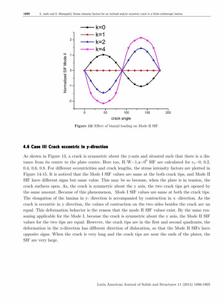
In order to study the effect of biaxial loading (configuration outlined in Figure 10) on the SIF for an inclined crack, the lamina dimensions are, H/W=1, a/w=0.2 α=0. Material properties are same as those in the previous case. Figure 11, 12 show the variation of Mode I and Mode II SIF respec-tively with various biaxial loading factors and crack angles. Biaxial loading factor k=1, Mode I SIF values are symmetric about a vertical line passing through crack angle 900. For k=1, Mode I SIF is independent of the crack angle. .It is seen that when biaxial loading factor k=1, YII is independent of crack angle and its value is zero. Mode II SIF is zero for crack angles 00,900,1800 irrespective of value of k. Except for k=1 Mode I and Mode II SIF show the sinusoidal variation with maxi-ma/minima occurring at crack angle 900 for Mode I SIF and that occurring at 450/1350 for Mode II SIF.

1898 S. Joshi and S. Manepatil/ Stress intensity factors for an inclined and/or eccentric crack in a finite orthotropic lamina
Latin American Journal of Solids and Structures 11 (2014) 1886-1905
Figure 10: An inclined central crack subjected to biaxial loading.
Figure 11: Effect of biaxial loading on Mode I SIF.
1899 S. Joshi and S. Manepatil/ Stress intensity factors for an inclined and/or eccentric crack in a finite orthotropic lamina
Latin American Journal of Solids and Structures 11 (2014) 1886-1905
Figure 12: Effect of biaxial loading on Mode II SIF.
4.6 Case III Crack eccentric in y-direction
As shown in Figure 13, a crack is symmetric about the y-axis and situated such that there is a dis-tance from its centre to the plate centre. Here too, H/W=1,α=00 SIF are calculated for ey=0, 0.2, 0.4, 0.6, 0.8. For different eccentricities and crack lengths, the stress intensity factors are plotted in Figure 14-15. It is noticed that the Mode I SIF values are same at the both crack tips, and Mode II SIF have different signs but same value. This may be so because, when the plate is in tension, the crack surfaces open. As, the crack is symmetric about the y axis, the two crack tips get opened by the same amount. Because of this phenomenon, Mode I SIF values are same at both the crack tips. The elongation of the lamina in y- direction is accompanied by contraction in x -direction. As the crack is eccentric in y direction, the values of contraction on the two sides besides the crack are un equal. This deformation behavior is the reason that the mode II SIF values exist. By the same rea-soning applicable for the Mode I, because the crack is symmetric about the y axis, the Mode II SIF values for the two tips are equal. However, the crack tips are in the first and second quadrants, the deformation in the x-direction has different direction of dislocation, so that the Mode II SIFs have opposite signs. When the crack is very long and the crack tips are near the ends of the plates, the SIF are very large.

1900 S. Joshi and S. Manepatil/ Stress intensity factors for an inclined and/or eccentric crack in a finite orthotropic lamina
Latin American Journal of Solids and Structures 11 (2014) 1886-1905
Figure 13: A crack eccentric in y-direction.
Figure 14: Mode I SIF for crack eccentric in y direction.

1901 S. Joshi and S. Manepatil/ Stress intensity factors for an inclined and/or eccentric crack in a finite orthotropic lamina
Latin American Journal of Solids and Structures 11 (2014) 1886-1905
Figure 15: Mode II SIF for crack eccentric in y direction.
4.7 Case IV Crack eccentric in x-direction
Figure 16 shows the of crack eccentric in x-direction with H/W=1, α=00. Fig. 17 and 18 show the SIF for the right and left crack tips respectively. Here only Mode I SIF exist which are different at the two crack tips. The ratio, SIF at right crack tip to that at left crack tip increases with increase in the crack length. Considerable increment in this ratio is found only after a/w is greater than or equal to 0.3. For a/w greater than 0.5 minimum value of the ratio is 2.5.
Figure 16: A crack eccentric in x direction.

1902 S. Joshi and S. Manepatil/ Stress intensity factors for an inclined and/or eccentric crack in a finite orthotropic lamina
Latin American Journal of Solids and Structures 11 (2014) 1886-1905
Figure 17: Mode I SIF at right crack tip for crack eccentric in x direction.
Figure 18: Mode I SIF at left crack tip for crack eccentric in x direct.
4.8 Case V An inclined crack eccentric in both x and y directions
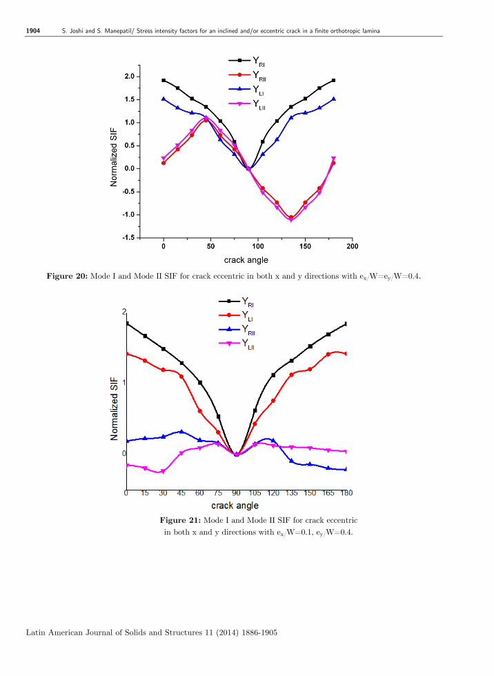
Figure 19 shows the configuration of an inclined crack eccentric in x and y both directions. Here, H/W=1, ex/W=ey/W=0.4 and a/W=0.2. Figure. 20 shows the variation of normalized Mode I and Mode II SIF at both crack tips with the crack angle θ. The maxima for Mode I occurs at θ=00, 1800 and minima occurs at θ=900, whereas, the maxima for Mode II occurs at θ=450, minima oc-

1903 S. Joshi and S. Manepatil/ Stress intensity factors for an inclined and/or eccentric crack in a finite orthotropic lamina
Latin American Journal of Solids and Structures 11 (2014) 1886-1905
curs at θ=1350. The maxima and minima for a given mode occur at the same crack angle for both the tips. Because the crack tips are in the same quadrant, the shear deformation of at the two tips has same sign, so is for Mode II SIF values. The nature of variation coincides with that for k=0 under the study of effect of biaxial loading. Also, the results for H/W=1, ex/W=0.1, ey/W=0.4 and a/W=0.2 are plotted in Fig. 21 indicating that except crack angle = 900 , difference in Mode II SIF is higher as compared to results with ex/W=ey/W=0.4.
Figure 19: A crack eccentric in both x and y directions.
1904 S. Joshi and S. Manepatil/ Stress intensity factors for an inclined and/or eccentric crack in a finite orthotropic lamina
Latin American Journal of Solids and Structures 11 (2014) 1886-1905
Figure 20: Mode I and Mode II SIF for crack eccentric in both x and y directions with ex/W=ey/W=0.4.
Figure 21: Mode I and Mode II SIF for crack eccentric in both x and y directions with ex/W=0.1, ey/W=0.4.

1905 S. Joshi and S. Manepatil/ Stress intensity factors for an inclined and/or eccentric crack in a finite orthotropic lamina
Latin American Journal of Solids and Structures 11 (2014) 1886-1905
5. CONCLUSIONS
Stress functions are defined in this formulation for calculation of Mode I and Mode II SIF of an central crack, inclined crack and crack eccentric in x and / or y direction for finite orthotropic lam-ina such that governing equations in the domain, stress free condition on the crack surface are satis-fied and also, the inverse square root singularity exists at the crack tips. The force type and stress boundary condition on the periphery of the lamina are satisfied by boundary collocation using least square method. The comparison of results with those in literature and with the finite element soft-ware ANSYS found in good agreement. References Beom H G, Jang H S. (2011). A wedge crack in an anisotropic material under anti plane shear. International Journal of Engineering Sciences, 49:867-880. Bowie O L , Freese C E. (1972). Central crack in plane orthotropic rectangular sheet. International Journal of Frac-ture, 8: 49-58. Chen Yi Zhou, Chen Yi Heng. (1981). A mixed boundary problem for finite internally cracked plate. Engineering Fracture Mechanics 14: 741-751. Ghorashi S S, Mohammadi S, Reza Saeed. (2011). Orthotropic enriched element free Galerkin method for fracture analysis of composites. Engineering Fracture Mechanics 78: 1906-1927. Karami G , Fenner R T. (1986). Analysis of mixed mode fracture and crack closure using the boundary integral equation method. International Journal of Fracture, 30:13-29. Lekhnitskii S G. Anisotropic Plates. (1968). Gordon and Breach Science Publishers, Newyork. Newman J. C. (1976). An improved method for collocation for the stress analysis of cracked plates with various shaped boundaries. NASA TN. D-6376: 1-45. Ozkan U, Nied H F, Kaya A C. (2010). Fracture analysis of anisotropic materials using enriched crack tip ele-ments. Engineering Fracture Mechanics, 77: 1191-1202. Ryan R L and Mall S. (1989). Edge cracks in a laminated cross ply strip. International Journal of Fracture 40: 127-141. Tan C L and Gao Y L. (1992). Boundary integral equation fracture mechanics analysis of plane orthotropic bodies, International Journal of Fracture 53: 343-365. Ukadgaonkar V. G. , Murali B. (1991). Stress intensity factors for finite plate by boundary collocation, Interna-tional Journal of Fracture, 52 : R17-R24. Wang S S , Yau J F , Corten H. (1980). A mixed mode crack analysis of rectilinear anisotropic solids using conser-vation laws of elasticity. International Journal of Fracture, 16: 247-259. Wang Y H, Cheung Y K. (1994). Boundary collocation method for cracks emanating from a hole in an anisotropic plate. , Engineering Fracture Mechanics. 48: 53-62. Wang Y H , Tham L G , Lee, Y Tsui P K K. (2003). A boundary collocation method for cracked plates. Comput-ers and Structures , 81: 2621-2630. Wang J G, Ju D Y, Sun M J, Li S L. (2011). A new analytical method for stress intensity actors based on insi-tumeasurementof crack deformation under biaxial loading. Materials and Design. 32, 664-670. Woo C W , Samson Chan L W . (1993). Composite laminate crack problems using boundary collocation method. Engineering Fracture Mechanics 45: 559-574.