Embed Size (px)
Citation preview
Design Tools for Reinforced3D DNA Nanostructures
Supervisor: Prof. Pekka OrponenAdvisor: Dr. Eugen Czeizler
Bachelor thesis by:Oriol Corcoll Andreu
Contents
1 Introduction 11.1 Problem statement . . . . . . . . . . . . . . . . . . . . . . . . 21.2 Structure of the thesis . . . . . . . . . . . . . . . . . . . . . . 2
2 Background 32.1 DNA as a nanomaterial . . . . . . . . . . . . . . . . . . . . . . 32.2 DNA origami . . . . . . . . . . . . . . . . . . . . . . . . . . . 42.3 Eulerian circuit . . . . . . . . . . . . . . . . . . . . . . . . . . 62.4 Valid stapled path . . . . . . . . . . . . . . . . . . . . . . . . 8
3 Scaffold path design 93.1 Scaffold path on DNA origami . . . . . . . . . . . . . . . . . . 103.2 Reinforcement design . . . . . . . . . . . . . . . . . . . . . . . 113.3 Scaffold path on a reinforced structure . . . . . . . . . . . . . 13
4 Reinforcement algorithm 144.1 Structure design . . . . . . . . . . . . . . . . . . . . . . . . . . 154.2 Avoiding overlapping . . . . . . . . . . . . . . . . . . . . . . . 184.3 Path over the structure . . . . . . . . . . . . . . . . . . . . . . 19
5 Visualisation 20
6 Conclusions 22
7 Bibliography 23
1
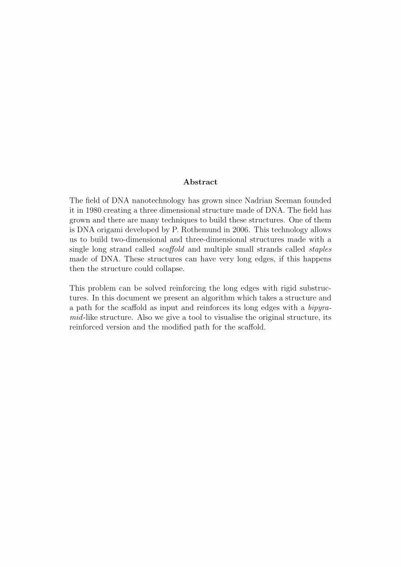
Abstract
The field of DNA nanotechnology has grown since Nadrian Seeman foundedit in 1980 creating a three dimensional structure made of DNA. The field hasgrown and there are many techniques to build these structures. One of themis DNA origami developed by P. Rothemund in 2006. This technology allowsus to build two-dimensional and three-dimensional structures made with asingle long strand called scaffold and multiple small strands called staplesmade of DNA. These structures can have very long edges, if this happensthen the structure could collapse.
This problem can be solved reinforcing the long edges with rigid substruc-tures. In this document we present an algorithm which takes a structure anda path for the scaffold as input and reinforces its long edges with a bipyra-mid -like structure. Also we give a tool to visualise the original structure, itsreinforced version and the modified path for the scaffold.
1 Introduction
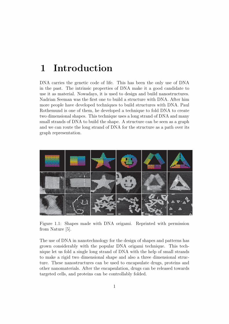
DNA carries the genetic code of life. This has been the only use of DNAin the past. The intrinsic properties of DNA make it a good candidate touse it as material. Nowadays, it is used to design and build nanostructures.Nadrian Seeman was the first one to build a structure with DNA. After himmore people have developed techniques to build structures with DNA. PaulRothemund is one of them, he developed a technique to fold DNA to createtwo dimensional shapes. This technique uses a long strand of DNA and manysmall strands of DNA to build the shape. A structure can be seen as a graphand we can route the long strand of DNA for the structure as a path over itsgraph representation.
Figure 1.1: Shapes made with DNA origami. Reprinted with permissionfrom Nature [5].
The use of DNA in nanotechnology for the design of shapes and patterns hasgrown considerably with the popular DNA origami technique. This tech-nique let us fold a single long strand of DNA with the help of small strandsto make a rigid two dimensional shape and also a three dimensional struc-ture. These nanostructures can be used to encapsulate drugs, proteins andother nanomaterials. After the encapsulation, drugs can be released towardstargeted cells, and proteins can be controllably folded.
1
CHAPTER 1. INTRODUCTION
1.1 Problem statement
Huge three dimensional structures can be made with the DNA origami tech-nique. These huge structures could have large edges which can affect to therigidity of the structure. A structure which is not rigid enough can be de-formed or even collapse. To avoid this situation these large edges have tobecome rigid. We can achieve this by replacing the original large edge witha new rigid structure.
We have designed an algorithm that takes a structure and a path over thestructure as input and reinforce the large edges in the structure and modi-fies the original path to go through the reinforced structure. The algorithmoutputs the reinforced structure and the new path over it. Also we havedeveloped a visualiser that takes a structure and a path as input and showsa three dimensional representation of the structure where we can navigate tosee it. We can see also the path through an animation.
1.2 Structure of the thesis
In Chapter 2, we expose the basic concepts that we will need to understandthis document. We talk about the DNA as nanomaterial, how it is useful tobuild structures and which are the techniques to build those structures. Wealso give some basic definitions in the graph theory field and we define whatis a valid stapled path.
In Chapter 3, we discuss how the scaffold strand is elaborated and how it isused in the DNA origami method. We define the rigidity property and wepresent a rigid structure that we will use to reinforce a large structure.
In Chapter 4, an algorithm to reinforce large structures is presented. Weexplain the construction of the new reinforced structure from the originalstructure and how we modify the original path to go over the new structure.
In Chapter 5, the visualisation tool is exposed with an example. We alsoexplain the technology used to develop it.
In Chapter 6, we explain our conclusions about the problem and our so-lution.
Oriol Corcoll Andreu Page 2
2 Background
Nanotechnology is a technology that deals with small-sized materials, usu-ally between 1 nm and 100 nm. The materials in this size range have somespecific and valuable properties. The concept of arrangement of small com-ponents into complex assemblies is called bottom-up constructions. DNAnanotechnology makes use of this approach in combination of self-assembly,where these components rearrange autonomously, to organise stable struc-tures from molecular components.
Since Watson and Crick defined the structure and composition of DNA [1]different applications for DNA has appear. DNA was first used as a nano-material by Nadrian Seeman in 1980 [2]. Seeman and co-workers synthesizedthe first three dimensional nanoscale object, a cube in 1991 [3]. In 1998,Seeman in collaboration with Winfree published the creation of two dimen-sional lattices of tiles [4]. This tile-base approach has been used by Winfreeand Rothemund in the DNA computing field as Wang tiles to perform com-putations. DNA nanotechnology has been used in DNA computing, DNAnanorobots and DNA nanostructures.
The graph theory can help us to route the scaffold over a structure try-ing to minimise the amount of DNA used. In this section we will give somebasic concepts about graph theory like: paths, trails, circuits and Euleriangraphs.
2.1 DNA as a nanomaterial
As Watson and Crick showed, DNA has a double helix structure [1]. Eachstrand of the double helix is composed of nucleotides, adenine (A), cytosine(C), guanine (G) and thymine (T). The strands are connected by pairs of nu-cleotides, an adenine nucleotide can be paired only with a thymine nucleotideand a cytosine nucleotide can be paired only with a guanine nucleotide. De-pending on the sequence of nucleotides the strand is called a sense strandor an antisense strand. If a strand sequence has the same sequence as themessenger RNA then it is called sense strand, the complementary is calledantisense strand. There are three possible conformations of DNA: A-DNA,
3
CHAPTER 2. BACKGROUND
B-DNA and Z-DNA. Over all these conformations, B-DNA is the most com-mon form. It is 2.37 nm wide and 10 base pairs are 3.4 nm and the doublehelix makes a turn every 10.5 base pairs. The two helices are not equallyspaced along the axis, but asymmetrically as a minor groove and a majorgroove.
Self-assembly is the process where a collection of simple components, startingin a disorganised state, autonomously combine into a more complex structure.This process is done without external guidance, the components experienceonly local interactions and typically obey a simple set of rules that describehow they combine. DNA nanotechnology uses strands of DNA as compo-nents to self-assembly nanostructures. There are three approaches to designthe nanostructures: tile-based, folding and dynamic.
2.2 DNA origami
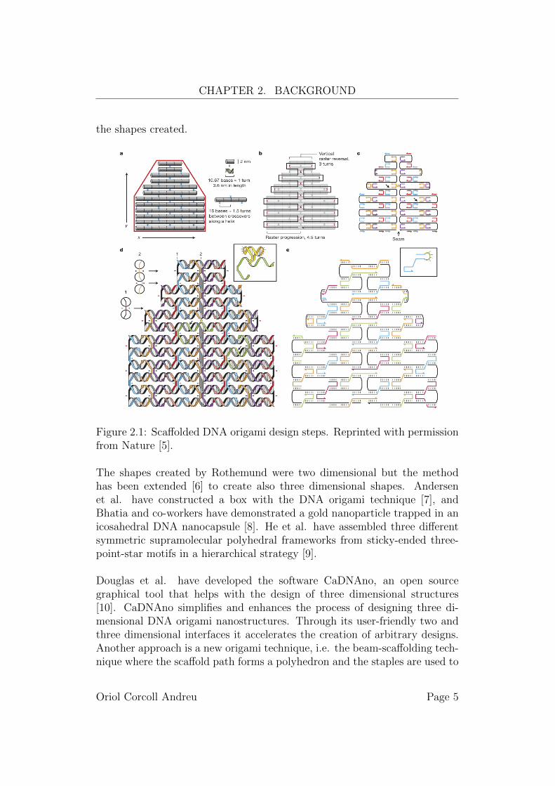
In 2006, Paul Rothemund [5] at the California Institute of Technology pro-posed a method to fold a long single strand of DNA called scaffold intoalmost arbitrary two dimensional shape with the help of short single strandsof DNA called staple strands. This method consists in five steps, the firsttwo by hand and the last three aided by computer.
The first step is to design a geometric model of a DNA structure that approx-imates the desired shape. The model is made with cylinders that representone turn of the helix and an array of crossovers that represent the places toput the staple strands. The second step proceeds by folding a single scaffoldstrand over the model designed at the first step. The only constraint on thefolding path is that the scaffold can be folded only at the locations where theDNA twist is at a tangent point between helices. The third step is the designof the staple strands corresponding to the complement of the sequence in thescaffold strand. In the fourth step, the twist of the scaffold is calculated andthe position is changed to minimise the strain. The last step merges adjacentstaple strands to yield fewer and longer strands.
Once the scaffold and the staple strands are designed to create the desiredshape, they are mixed in a pot and the mixture is rapidly heated, and thencooled to get the desired shape. In the Rothemund paper, the selected shapesto prove that the method works were squares, rectangles, triangles, stars andsmiley faces. He used the genomic DNA of the virus M13mp18 to create thoseshapes, and observed that the triangle was the most stable shape among all
Oriol Corcoll Andreu Page 4
CHAPTER 2. BACKGROUND
the shapes created.
Figure 2.1: Scaffolded DNA origami design steps. Reprinted with permissionfrom Nature [5].
The shapes created by Rothemund were two dimensional but the methodhas been extended [6] to create also three dimensional shapes. Andersenet al. have constructed a box with the DNA origami technique [7], andBhatia and co-workers have demonstrated a gold nanoparticle trapped in anicosahedral DNA nanocapsule [8]. He et al. have assembled three differentsymmetric supramolecular polyhedral frameworks from sticky-ended three-point-star motifs in a hierarchical strategy [9].
Douglas et al. have developed the software CaDNAno, an open sourcegraphical tool that helps with the design of three dimensional structures[10]. CaDNAno simplifies and enhances the process of designing three di-mensional DNA origami nanostructures. Through its user-friendly two andthree dimensional interfaces it accelerates the creation of arbitrary designs.Another approach is a new origami technique, i.e. the beam-scaffolding tech-nique where the scaffold path forms a polyhedron and the staples are used to
Oriol Corcoll Andreu Page 5
CHAPTER 2. BACKGROUND
fix the shape of the polyhedron. With this technique the designed structurehas to be triangulated in order to be rigid.
2.3 Eulerian circuit
A diagram with lines and dots is a useful tool to describe many real-worldsituations. We can represent concepts such as people and their relationshipsor cities and the road connections between them. A mathematical abstrac-tion of this concept is called a graph. A graph G is a pair of sets (V,E), whereV is the set of vertices, also written as V (G), and E is the set of edges, alsowritten as E(G). For our purposes we define an edge as a 2-element subsetof V , i.e., an edge is an unordered pair of vertices. We will allow multipleedges with same vertices, i.e.ei, ej ∈ E with ei = ej and i 6= j. Loops willnot be allowed, that is, for all e = {v, u} ∈ E it must be the case that v 6= u.Graphs with unordered pairs of vertices as edges are called undirected graphs.
Two vertices v, u ∈ V are adjacent if there is an edge {v, u} ∈ E. Ver-tices v and u are incident with the edge e = {v, u}. For a vertex v in V , thedegree of v is the number of incident edges of v in G and it is denoted by g(v).The minimum degree among all vertices of the graph is denoted by δ(G) andthe maximum by ∆(G). If the minimum degree equals the maximum degree,i.e. δ(G) = ∆(G), then G is called regular, or δ(G)-regular. As Euler provedin 1736, the sum of all degrees in a graph is twice the number of edges, that is,∑
v∈V (G) d(v) = 2|E(G)|. This theorem is also called the handshaking lemma.As a consequence of the theorem we have that the number of vertices withodd degree is even. Another important result derived from the handshakinglemma is that if a graph has exactly two vertices with odd degree then thereis a path between them [11].
Let G = (V,E) be a graph. A walk in G is a sequence v0,e1,v1,e2,...,en,vnwhere ei = {vi−1, vi} is an edge in E; n is the length of the sequence. If forall 1 ≤ i < j ≤ n we have ei 6= ej then the sequence is called a trail in G. Ifthe starting vertex of the trail and the ending vertex are the same then thetrail is called a circuit. If for all 0 ≤ i < j ≤ n we have vi 6= vj then thesequence is called a path in G. A graph is called connected if there is a pathbetween any pair of its vertices; otherwise, it is called disconnected. We willassume that our graphs are connected.
A graph with a trail that goes through all the edges in the graph has anEulerian trail and is called semi-Eulerian graph. Similarly, if a graph has a
Oriol Corcoll Andreu Page 6
CHAPTER 2. BACKGROUND
circuit that visits every edge in the graph then the graph has an Euleriancircuit and is called a Eulerian graph. As Euler showed in 1736 [11], the nec-essary condition for the existence of an Eulerian circuit is that every vertexin the graph has even degree. This condition is also sufficient, as was proved,137 years later, by Carl Hierholzer [12]. The proof was later published byWiener after the death of Hierholzer. This theorem can be extended to Eule-rian trails: there is an Eulerian trail if and only if there are only zero or twoodd degree vertices in the graph. More precisely, in the case of zero verticeswith odd degree we have an Eulerian circuit and in the other case we have anEulerian trail with different starting and ending vertices. There are two wellknown algorithms to find an Eulerian circuit in an Eulerian graph. The firstone is Fleury’s algorithm and was designed by M. Fleury in 1883, it works inO(|E|2). The results of Hierholzer gives a better linear time algorithm thanFleury’s algorithm. This result is important for us because we have to find apath for the scaffold that goes over every edge in the structure and we wouldlike to use every edge only once.
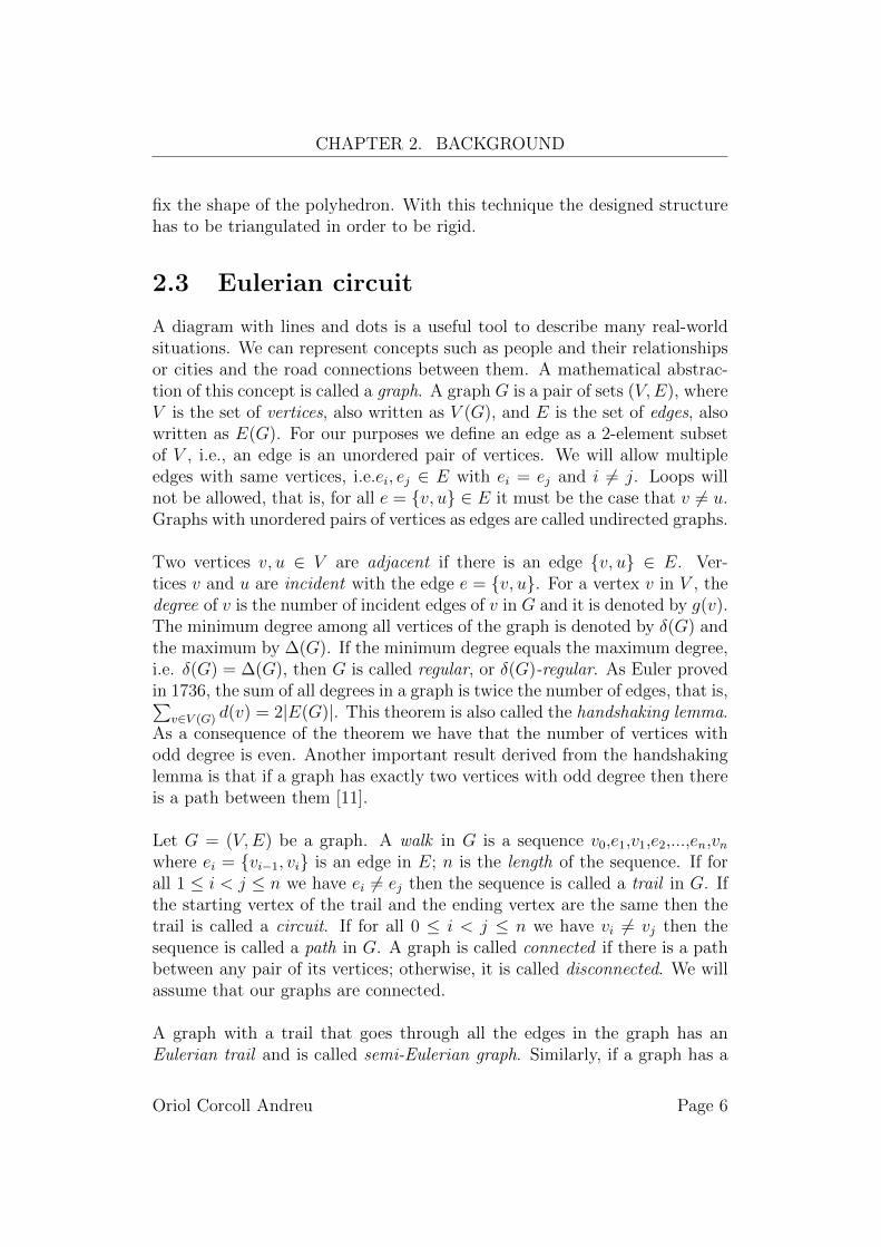
Eulerian graphs and semi-Eulerian graphs have many applications, e.g. routemaps for airplanes, planning a trip around the world or a tour in a museum.
Figure 2.2: Seven Bridges of Konigsberg.
Researchers have been sequencing all kinds of DNA, including the humangenome. The current methods to sequence DNA is to split the whole se-quence in smaller sequences. Assembling the sequences after processing eachof them is a complicated process. Pevzner et al. have used Eulerian graphs toassembly DNA fragments [13]. The proposed algorithm splits each sequencein smaller ones, and researchers can then see the sequences as an Euleriangraph with polynomial algorithms to assembly the sequences.
Another application is the circuit layout area minimisation problem, which
Oriol Corcoll Andreu Page 7
CHAPTER 2. BACKGROUND
is believed to be intractable. The order of the logic gates is a major factor inthis problem. Kuntal Roy [14] approaches this problem as an Eulerian graphwhere one tries to find an order for CMOS logic gates.
2.4 Valid stapled path
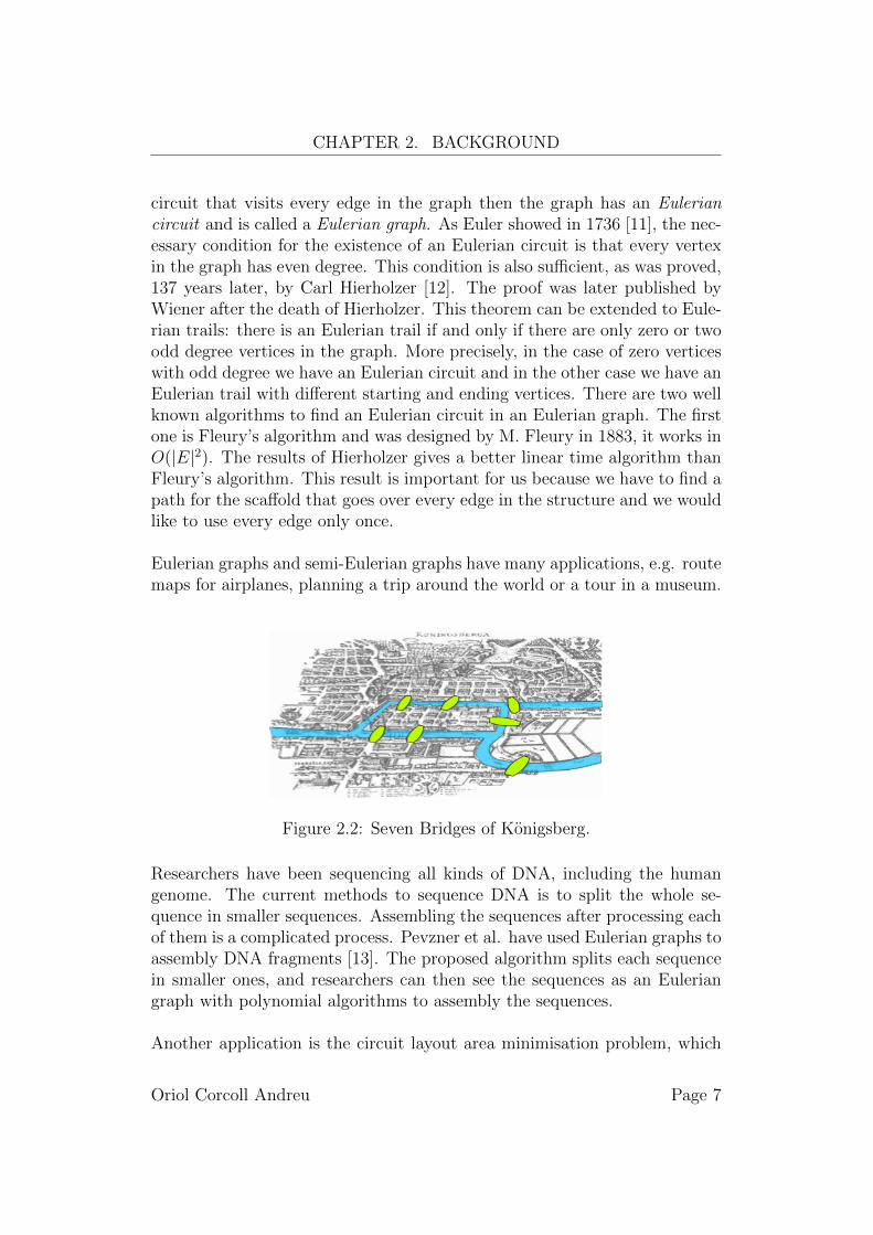
A beam structure can be represented by a graph where the joints in thestructure are vertices in the graph and the beams are edges. This conceptcan be used with nanoscale structures made of DNA. We can see the three di-mensional nanostructures made with the DNA origami technique as graphs.Similarly, we can see the scaffold path of the DNA nanostructure as an Eu-lerian trail in the graph, but over all these Eulerian trails only a subset ofthem are valid stapled paths.
Figure 2.3: Design of a beam structure as a graph, octahedron.
The nanostructure can be seen as a solid object, more precisely as a poly-hedron. A polyhedron is a solid object made of flat faces. We can define aface in our graphs analogously as a face in a polyhedron. As a consequenceof this definition of face we have that every edge is adjacent to exactly twofaces. An Eulerian trail is a valid stapled path if for every edge ei in the trail,the edge ei+1 is adjacent to one of the faces adjacent to ei. The purpose of apath over the structure is to have a path for the scaffold which makes a rigidstructure, to achieve this the path has to be a valid stapled path.
Oriol Corcoll Andreu Page 8
3 Scaffold path design
DNA origami allows us to create structures folding a single strand of DNAcalled scaffold and multiple small strands called staples. The design of thescaffold starts by determining the length of the strand. To get this size wehave to design a path over the structure. The path has to go through thewhole structure in such a way that the resulting structure is rigid enoughand trying to minimise the amount of DNA used.
Once we have a valid path over the structure the next step is to design thesequence of the scaffold and the staples. To achieve this we have to createa scaffold long enough to follow the designed path. Capello and co-workersare able to create synthetic DNA [15], from small strands up to thousands ofbase pairs with the sequence of nucleotides that we desire. However, this pro-cess is prohibitively expensive. Thus, as a second approach biological DNAis employed in DNA origami, i.e. the viral DNA of M13mp18. The bacteriaM13mp18 is the most common one used to make long scaffolds, it provides anatural sequence of 7,249 nucleotides and is the one used by Rothemund tocreate the shapes described in his paper. With the scaffold and the staplesdesigned, they are ready to blend with magnesium and anneal the solutionto form the structures.
Bhatia and co-workers [8] constructed an icosahedron to encapsulate goldparticles. They constructed the icosahedron by designing three differentcomponents. One of the components is common for the top and the bot-tom of the icosahedron. The two others are the middle parts which join thetop and the bottom. The result of this process is a DNA icosahedron whichcan hold a gold nanoparticle inside.
Ke and co-workers [16] designed a strategy to construct cages with a tetra-hedral geometry using the DNA origami technology, where each edge of thetetrahedron is 58nm in dimension.
9
CHAPTER 3. SCAFFOLD PATH DESIGN
3.1 Scaffold path on DNA origami
A polyhedron is said to be rigid if it can not be deformed. A convex poly-hedron is rigid if all its surfaces are rigid, as Alexandrov showed [17]. It isenough for a convex polyhedron to have every face as a triangle in order tobe rigid [18]. We assume all our structures are convex polyhedra.
Given a graph representing a convex polyhedron, we have to find a pathover it. In order to make the structure rigid the path has to go throughevery edge of the graph. This restriction is a lower bound for the numberof edges that we have to use, that is, the path has to cover at least onceevery edge. But, in order to minimise the amount of DNA used we have tominimise the number of edges that we use. This restriction makes a desir-able upper bound for the number of edges in the path, that is, it is moreconvenient to use every edge at most once. These two bounds lead us to theproblem of finding an Eulerian circuit in the graph.
Since an Eulerian circuit exists if and only if the degrees of all vertices areeven. Thus, if the graph is Eulerian then there is a way to place the scaffoldover the structure. But, what happens when the graph is not Eulerian? Asa consequence of the handshaking lemma we know that the number of odddegree vertices is even, and we can modify the graph by adding a minimumnumber of double edges such that the degree of all the vertices in the graphbecomes even [19]. Thus, we have to ensure that every polyhedron has apath for the scaffold.
Bjorn Hogberg and his team have developed a origami technique for an icosa-hedral framework [20]. They implemented a icosahedron by subdividing itsfaces and routing the scaffold over the edges of the icosahedron. The stapleswere used to fix the vertices on the designed path. Abdulmelik Mohammedat the university of Aalto in Finland has extended Bjorn’s work to arbitrarypolyhedral beam-framework [21]. Also, he has investigated the conditionswhere the scaffold can be routed in an arbitrary polyhedron. Moreover, hestatements that the problem of find a path for the scaffold in an arbitrarypolyhedron is NP-Complete and presents a backtracking algorithm whichtakes a polyhedron and finds a path for the scaffold in it, if such a pathexists.
Oriol Corcoll Andreu Page 10
CHAPTER 3. SCAFFOLD PATH DESIGN
3.2 Reinforcement design
A large structure can be made of DNA using the DNA origami technique,but if the edges are long enough, e.g. larger than 70 base pairs, the struc-ture could be deformed or even collapse. In order to avoid this behaviour wepropose a structure to reinforce large edges in the original structure.
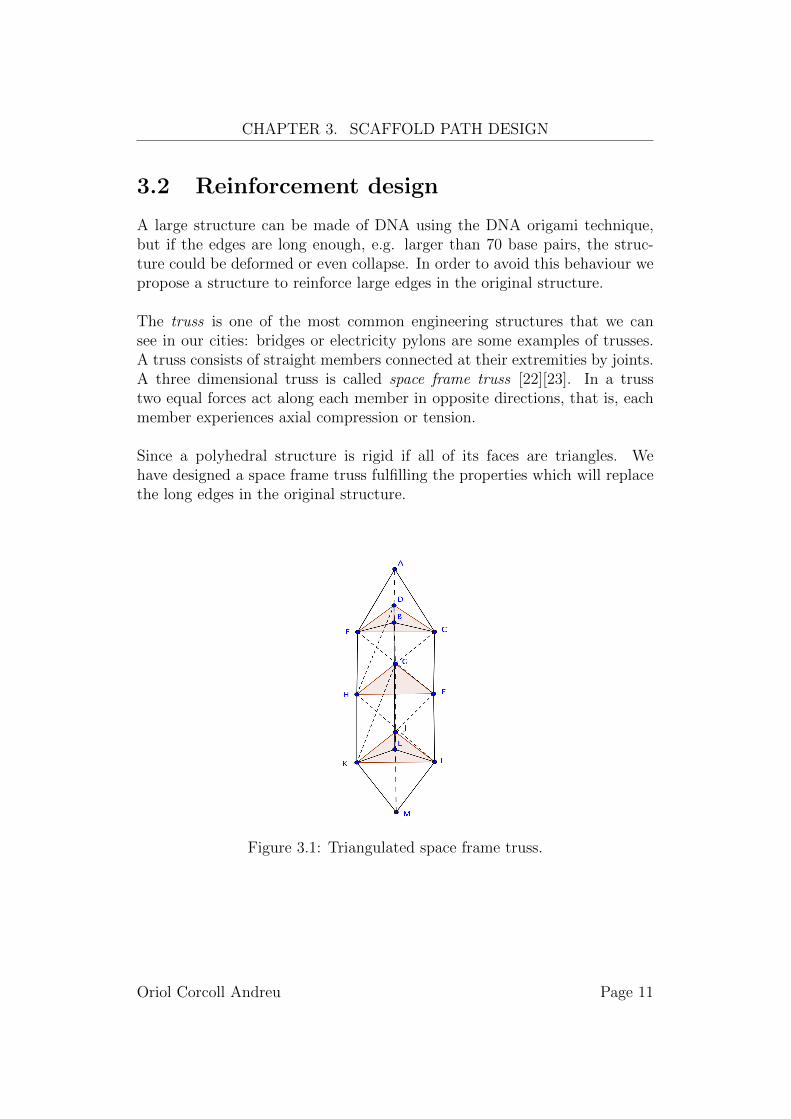
The truss is one of the most common engineering structures that we cansee in our cities: bridges or electricity pylons are some examples of trusses.A truss consists of straight members connected at their extremities by joints.A three dimensional truss is called space frame truss [22][23]. In a trusstwo equal forces act along each member in opposite directions, that is, eachmember experiences axial compression or tension.
Since a polyhedral structure is rigid if all of its faces are triangles. Wehave designed a space frame truss fulfilling the properties which will replacethe long edges in the original structure.
Figure 3.1: Triangulated space frame truss.
Oriol Corcoll Andreu Page 11
CHAPTER 3. SCAFFOLD PATH DESIGN
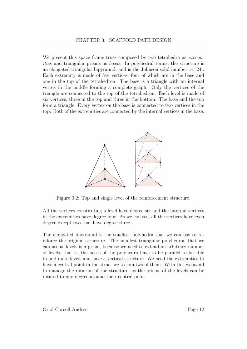
We present this space frame truss composed by two tetrahedra as extrem-ities and triangular prisms as levels. In polyhedral terms, the structure isan elongated triangular bipyramid, and is the Johnson solid number 14 [24].Each extremity is made of five vertices, four of which are in the base andone in the top of the tetrahedron. The base is a triangle with an internalvertex in the middle forming a complete graph. Only the vertices of thetriangle are connected to the top of the tetrahedron. Each level is made ofsix vertices, three in the top and three in the bottom. The base and the topform a triangle. Every vertex on the base is connected to two vertices in thetop. Both of the extremities are connected by the internal vertices in the base.
Figure 3.2: Top and single level of the reinforcement structure.
All the vertices constituting a level have degree six and the internal verticesin the extremities have degree four. As we can see, all the vertices have evendegree except two that have degree three.
The elongated bipyramid is the smallest polyhedra that we can use to re-inforce the original structure. The smallest triangular polyhedron that wecan use as levels is a prism, because we need to extend an arbitrary numberof levels, that is, the bases of the polyhedra have to be parallel to be ableto add more levels and have a vertical structure. We need the extremities tohave a central point in the structure to join two of them. With this we avoidto manage the rotation of the structure, as the prisms of the levels can berotated to any degree around their central point.
Oriol Corcoll Andreu Page 12
CHAPTER 3. SCAFFOLD PATH DESIGN
3.3 Scaffold path on a reinforced structure
The above structure clearly fulfills the property of rigidity because every facein the structure is a triangle, this is enough for a structure to be rigid. Thesecond property that this structure has is that it is a semi-Eulerian graph,i.e. it has an Eulerian trail. This is true because the structure has only twoodd vertices. These vertices are extremities of the bipyramid, i.e., the twovertices from the top of the two tetrahedra.
To reinforce the original structure with the designed bipyramid, we haveto go through the edges of the original structure and replace the long edgeswith our structure. The structure is very convenient for our propose, becausewe can start the global path at one extremity, go through each edge of thestructure, and finish on the other extremity and this is easily archivable be-cause the structure has an Eulerian trail.
We have designed this trail in a constructive way, that is, we give a sequenceof vertices starting from an odd degree vertex and covering the extremity.After the extremity we continue covering level by level the structure until wereach and cover the other extremity. The trail can be extended automaticallyto an arbitrary number of levels. Thus the exact path is described in Section4.3.
Oriol Corcoll Andreu Page 13
4 Reinforcement algorithm
In chapter 2 we described the basic concepts of DNA and graph theory thatare needed to understand the problem and the algorithm. In chapter 3 wepresented how the scaffold design works and the rigidity problems when de-signing three dimensional structures. In this chapter we present a construc-tive algorithm for the reinforcement of a DNA nanostructure. Given a graphthat represents a polyhedron and a path over the graph, we construct thenew reinforced graph which represents the reinforced polyhedron. The algo-rithm outputs a set of vertices and a trail over the new structure. It proceedsas follows:
First, we read the graph and the path which defines the polyhedron. Theexpected input for the definition of the graph is a file with extension ply:
ply // Start header
...
end_header // End Header
x1 y1 z1 // Float coordinates for vertex 1
... // Rest of vertices
and for the path is a file with extension ntrail:
v1 v2 ... vN // Path for the structure
After reading the input, we reinforce only the long edges with our reinforcingstructure. This reinforcement is done in the same order that the given path.If the given path is an Eulerian circuit over the original structure then thepath over the reinforced structure will also be an Eulerian circuit.
The reinforcement of an edge is done only if the length of the edge is greaterthan a predefined threshold. Every edge is defined by two vertices. We takethese two vertices and create the new structure between them, where the twoodd vertices of the new structure are the two vertices in the original structure.The next section describes how the structure is created and placed.
14
CHAPTER 4. REINFORCEMENT ALGORITHM
4.1 Structure design
We work in Euclidean spaces with points defined as triplets of real numbers.Given two Euclidean points p and q, the distance between them is given bythe formula:
d(p, q) =√
(px − qx)2 + (py − qy)2 + (pz − qz)2 (4.1)
Now, let h be the height of a single level in the reinforcement structure, thenthe number n of levels in the edge reinforcement is:
n = bd(p, q)
hc − (2 + extra) (4.2)
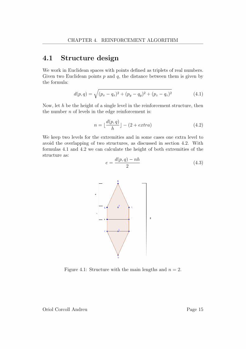
We keep two levels for the extremities and in some cases one extra level toavoid the overlapping of two structures, as discussed in section 4.2. Withformulas 4.1 and 4.2 we can calculate the height of both extremities of thestructure as:
e =d(p, q)− nh
2(4.3)
Figure 4.1: Structure with the main lengths and n = 2.
Oriol Corcoll Andreu Page 15
CHAPTER 4. REINFORCEMENT ALGORITHM
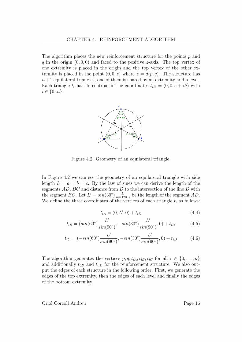
The algorithm places the new reinforcement structure for the points p andq in the origin (0, 0, 0) and faced to the positive z-axis. The top vertex ofone extremity is placed in the origin and the top vertex of the other ex-tremity is placed in the point (0, 0, z) where z = d(p, q). The structure hasn+1 equilateral triangles, one of them is shared by an extremity and a level.Each triangle ti has its centroid in the coordinates tiD = (0, 0, e + ih) withi ∈ {0..n}.
Figure 4.2: Geometry of an equilateral triangle.
In Figure 4.2 we can see the geometry of an equilateral triangle with sidelength L = a = b = c. By the law of sines we can derive the length of thesegments AD, BC and distance from D to the intersection of the line D withthe segment BC. Let L′ = sin(30◦) L
sin(120◦)be the length of the segment AD.
We define the three coordinates of the vertices of each triangle ti as follows:
tiA = (0, L′, 0) + tiD (4.4)
tiB = (sin(60◦)L′
sin(90◦),−sin(30◦)
L′
sin(90◦), 0) + tiD (4.5)
tiC = (−sin(60◦)L′
sin(90◦),−sin(30◦)
L′
sin(90◦), 0) + tiD (4.6)
The algorithm generates the vertices p, q, tiA, tiB, tiC for all i ∈ {0, . . . , n}and additionally t0D and tnD for the reinforcement structure. We also out-put the edges of each structure in the following order. First, we generate theedges of the top extremity, then the edges of each level and finally the edgesof the bottom extremity.
Oriol Corcoll Andreu Page 16
CHAPTER 4. REINFORCEMENT ALGORITHM
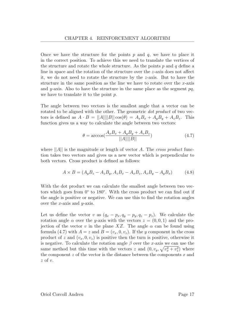
Once we have the structure for the points p and q, we have to place itin the correct position. To achieve this we need to translate the vertices ofthe structure and rotate the whole structure. As the points p and q define aline in space and the rotation of the structure over the z-axis does not affectit, we do not need to rotate the structure by the z-axis. But to have thestructure in the same position as the line we have to rotate over the x-axisand y-axis. Also to have the structure in the same place as the segment pq,we have to translate it to the point p.
The angle between two vectors is the smallest angle that a vector can berotated to be aligned with the other. The geometric dot product of two vec-tors is defined as A · B = ||A||||B|| cos(θ) = AxBx + AyBy + AzBz. Thisfunction gives us a way to calculate the angle between two vectors:
θ = arccos(AxBx + AyBy + AzBz
||A||||B||) (4.7)
where ||A|| is the magnitude or length of vector A. The cross product func-tion takes two vectors and gives us a new vector which is perpendicular toboth vectors. Cross product is defined as follows:
A×B = (AyBz − AzBy, AzBx − AxBz, AxBy − AyBx) (4.8)
With the dot product we can calculate the smallest angle between two vec-tors which goes from 0◦ to 180◦. With the cross product we can find out ifthe angle is positive or negative. We can use this to find the rotation anglesover the x-axis and y-axis.
Let us define the vector v as (qx − px, qy − py, qz − pz). We calculate therotation angle α over the y-axis with the vectors z = (0, 0, 1) and the pro-jection of the vector v in the plane XZ. The angle α can be found usingformula (4.7) with A = z and B = (vx, 0, vz). If the y component in the crossproduct of z and (vx, 0, vz) is positive then the turn is positive, otherwise itis negative. To calculate the rotation angle β over the x-axis we can use thesame method but this time with the vectors z and (0, vy,
√v2x + v2z) where
the component z of the vector is the distance between the components x andz of v.
Oriol Corcoll Andreu Page 17
CHAPTER 4. REINFORCEMENT ALGORITHM
4.2 Avoiding overlapping
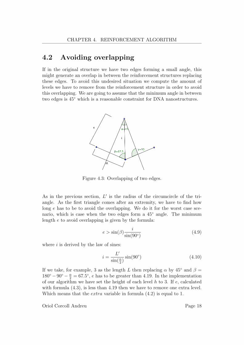
If in the original structure we have two edges forming a small angle, thismight generate an overlap in between the reinforcement structures replacingthese edges. To avoid this undesired situation we compute the amount oflevels we have to remove from the reinforcement structure in order to avoidthis overlapping. We are going to assume that the minimum angle in betweentwo edges is 45◦ which is a reasonable constraint for DNA nanostructures.
Figure 4.3: Overlapping of two edges.
As in the previous section, L′ is the radius of the circumcircle of the tri-angle. As the first triangle comes after an extremity, we have to find howlong e has to be to avoid the overlapping. We do it for the worst case sce-nario, which is case when the two edges form a 45◦ angle. The minimumlength e to avoid overlapping is given by the formula:
e > sin(β)i
sin(90◦)(4.9)
where i is derived by the law of sines:
i =L′
sin(α2)
sin(90◦) (4.10)
If we take, for example, 3 as the length L then replacing α by 45◦ and β =180◦− 90◦− α
2= 67.5◦, e has to be greater than 4.19. In the implementation
of our algorithm we have set the height of each level h to 3. If e, calculatedwith formula (4.3), is less than 4.19 then we have to remove one extra level.Which means that the extra variable in formula (4.2) is equal to 1.
Oriol Corcoll Andreu Page 18
CHAPTER 4. REINFORCEMENT ALGORITHM
4.3 Path over the structure
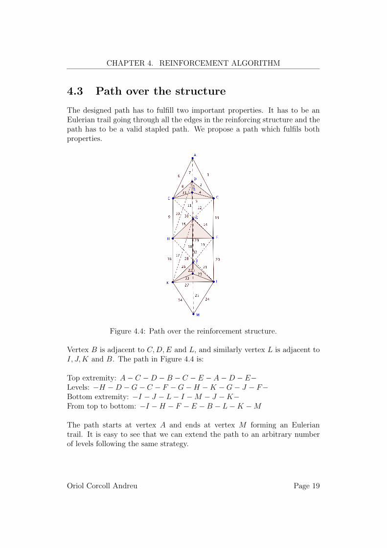
The designed path has to fulfill two important properties. It has to be anEulerian trail going through all the edges in the reinforcing structure and thepath has to be a valid stapled path. We propose a path which fulfils bothproperties.
Figure 4.4: Path over the reinforcement structure.
Vertex B is adjacent to C,D,E and L, and similarly vertex L is adjacent toI, J,K and B. The path in Figure 4.4 is:
Top extremity: A− C −D −B − C − E − A−D − E−Levels: −H −D −G− C − F −G−H −K −G− J − F−Bottom extremity: −I − J − L− I −M − J −K−From top to bottom: −I −H − F − E −B − L−K −M
The path starts at vertex A and ends at vertex M forming an Euleriantrail. It is easy to see that we can extend the path to an arbitrary numberof levels following the same strategy.
Oriol Corcoll Andreu Page 19
5 Visualisation
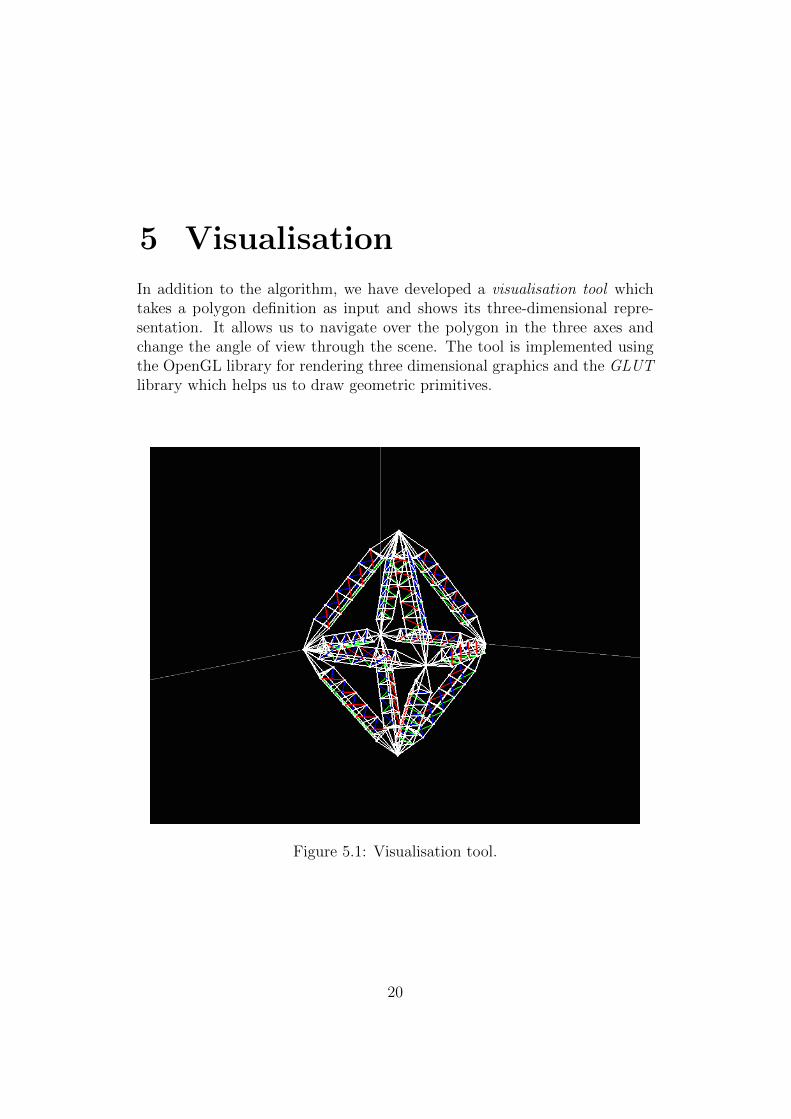
In addition to the algorithm, we have developed a visualisation tool whichtakes a polygon definition as input and shows its three-dimensional repre-sentation. It allows us to navigate over the polygon in the three axes andchange the angle of view through the scene. The tool is implemented usingthe OpenGL library for rendering three dimensional graphics and the GLUTlibrary which helps us to draw geometric primitives.
Figure 5.1: Visualisation tool.
20
CHAPTER 5. VISUALISATION
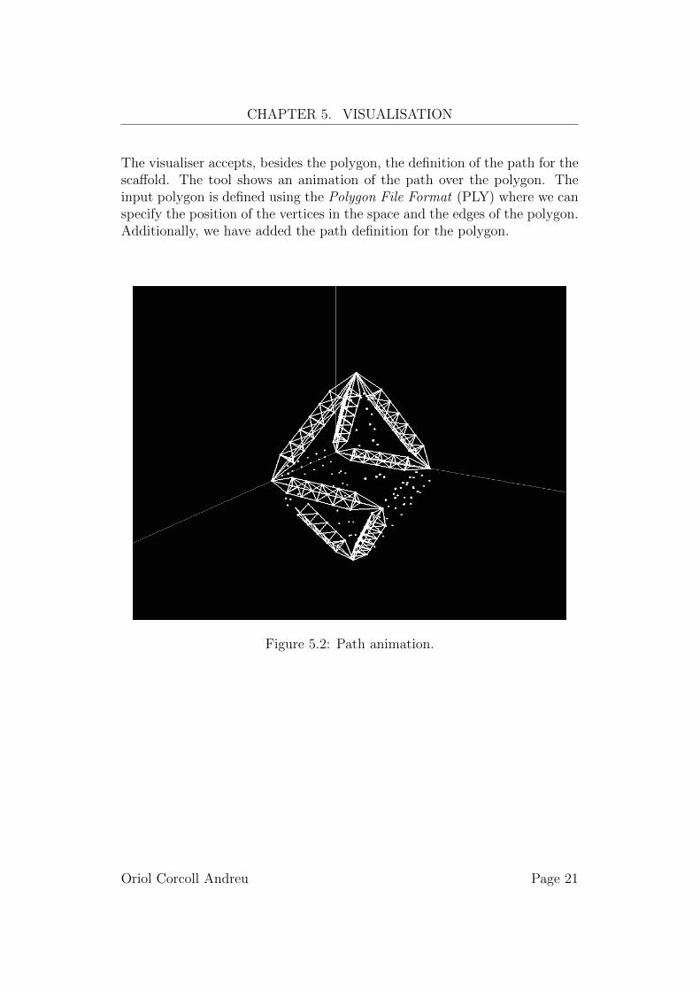
The visualiser accepts, besides the polygon, the definition of the path for thescaffold. The tool shows an animation of the path over the polygon. Theinput polygon is defined using the Polygon File Format (PLY) where we canspecify the position of the vertices in the space and the edges of the polygon.Additionally, we have added the path definition for the polygon.
Figure 5.2: Path animation.
Oriol Corcoll Andreu Page 21
6 Conclusions
In this document, we discuss the DNA origami technique and how it workswith two-dimensional shapes and three dimensional structures. We have ex-posed the problematic of building large structures with DNA. We propose amethod to avoid the collapse reinforcing those large structures.
We presented a bipyramid-like structure which the vertices on the top ofeach pyramid are the only ones with degree odd. This very convenient forour purposes because the rotation over its vertical axis does not affect theresulting global structure. Additionally, the structure fulfils the rigidity re-quirements, since it is triangulated. Moreover, we have defined a valid stapledpath in section 3.3 and we showed in section 4.3 the constructive design of avalid stapled path over the structure.
We propose a constructive algorithm which takes a polyhedron definitionwith a path, then it reinforces the original structure with our bipyramid de-sign. The algorithm works following the given path for the original structureand for every edge, it creates a new reinforcement structure. Then translatesand rotates the new structure to be aligned with the vertices of the edge, i.e.the vertices of the edge are the top vertices of the two pyramids. Once thestructure is in place, the algorithm modifies the original path to go throughthe new structure.
Also, we have developed a visualisation tool which takes a polyhedron anda path definition. It shows the polyhedron representation and an animationwhere we can see the designed path for the polyhedron. We can navigateover the polyhedron and look at it in different angles.
22
Bibliography
[1] Watson J.D. and Crick F.H.C. A structure for deoxyribose nucleic acid.Nature 171, (1953), 737-738.
[2] Seeman, N. Nucleic acid junctions and lattices. Journal of TheoreticalBiology 99, (1982), 237-47.
[3] Chen, J. and Seeman, N. Synthesis from DNA of a molecule with theconnectivity of a cube. Nature 350, (1991), 631-3.
[4] Winfree, E., Liu, F., Wenzler, L. and Seeman, N. Design and self-assembly of two-dimensional DNA crystals. Nature 394, (1998), 529–544.
[5] Rothemund, P. W. Folding DNA to Create Nanoscale Shapes and Pat-terns. Nature 440, 7082 (2006), 297–302.
[6] Douglas, S., Dietz, H., Liedl, T., Hogberg, B., Graf, F. and Shih, W.Self-assembly of DNA into nanoscale three-dimensional shapes. Nature459, (2009), 414-418.
[7] Andersen, E., Dong, E., Nielsen, M., Jahn, K., Subramani, R., Mam-douh, W., Golas, M., Sander, B., Stark, H., Oliveira, C., Pedersen, J.,Birkedal, V., Besenbacher, F., Gothelf, K. and Kjems, J. Self-assemblyof a nanoscale DNA box with a controllable lid. Nature 459, (2009),73-76.
[8] Bhatia, D., Mehtab, S., Krishnan, R., Indi, S. S., Basu, A., and Krish-nan, Y. Icosahedral DNA Nanocapsules by Modular Assembly. Ange-wandte Chemie International Edition 48, 23 (2009), 4134-4137.
[9] He, Y., Ye, T., Su, M., Zhang, C., Ribbe, A. E., Jiang, W., and Mao,C. Hierarchical Self-assembly of DNA into Symmetric SupramolecularPolyhedra. Nature 452, 7184 (2008), 198-201.
[10] Douglas, S. M., Marblestone, A. H., Teerapittayanon, S., Vazquez, A.,Church, G. M., and Shih, W. M. Rapid Prototyping of 3D DNA-origamiShapes with caDNAno. Nucleic Acids Research 37, 15 (2009), 5001-5006.
23
BIBLIOGRAPHY
[11] Euler, L. Solutio problematis ad geometriam situs pertinentis. Com-mentarii academiae scientiarum Petropolitanae, Vol. 8 (1741), 128-140.Reprinted in Opera Omnia Series Prima, Vol. 7. pp. 1-10, (1766).
[12] Hierholzer, C., Chr, W. Ueber die Moglichkeit, einen Linienzug ohneWiederholung und ohne Unterbrechung zu umfahren. MathematischeAnnalen (in German), (1873), 30–32.
[13] Pevzner, P., Tang, H. and Waterman, M. An Eulerian path approach toDNA fragment assembly. PNAS 98, 17 (2001), 9748–9753.
[14] Roy, K. Optimum Gate Ordering of CMOS Logic Gates Using EulerPath Approach: Some Insights and Explanations. Journal of Computingand Information Technology, 1 (2007), 85-92.
[15] Capello, J. and Causey, S.C. and Chambers, J. and Crissman, J.W.and Ferrari, F.A. and Pollock, T.J. and Richardson, C. Constructionof synthetic DNA and its use in large polypeptide synthesis. GooglePatents, (1993).
[16] Ke, Y. Sharma, J. Liu, M. Jahn, K. Liu, Y. and Yan, H. Scaffolded DNAOrigami of a DNA Tetrahedron Molecular Container. Nano Letters 6(2009), 2445-2447.
[17] Dairbekov, N., Alexandrov, A., Kutateladze, S., and Sossinsky, A. Con-vex Polyhedra. Springer, Berlin, Germany, (2005).
[18] Connelly, R. Rigidity of Certain Cabled Frameworks and the Second-Order Rigidity of Arbitrarily Triangulated Convex Surfaces. Adv. Math.37 (1980).
[19] Cromwell, P. R. Polyhedra. Cambridge University Press, ShaftesburyRd, Cambridge, United Kingdom, (1999).
[20] Areddy, P. K. Computer-Aided Design of Polyhedral DNA Nanostruc-tures. Master?s thesis, KTH, 2012.
[21] Mohammed, A. Combinatorial Algorithms for the Design of NanoscaleSystems. Master?s thesis, Aalto University, 2014.
[22] Hibbeler, R. Engineering Mechanics-Statics. New York: Macmillan Pub-lishing Co., Inc.
[23] Greene, C. Graphical analysis of roof trusses; for the use of engineers,architects and builders. New York, J. Wiley & sons (1885).
Oriol Corcoll Andreu Page 24
BIBLIOGRAPHY
[24] Johnson, N. W. Convex Solids with Regular Faces. Canadian Journal ofMathematics, 18 (1966), 169-200.
[25] Joyner, D. Van Nguyen, M. and Philips, D. Algorithmic Graph Theoryand Sage. 2013.
Oriol Corcoll Andreu Page 25