Embed Size (px)
Citation preview

Design Steps for Intake & Exhaust Systems
P M V SubbaraoProfessor
Mechanical Engineering Department
Acoustic Theory to maximize Volumetric Efficeincy ….
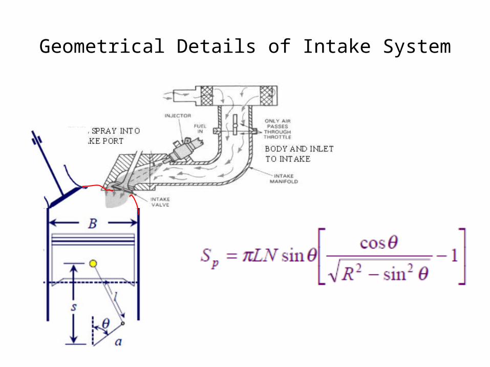
Geometrical Details of Intake System
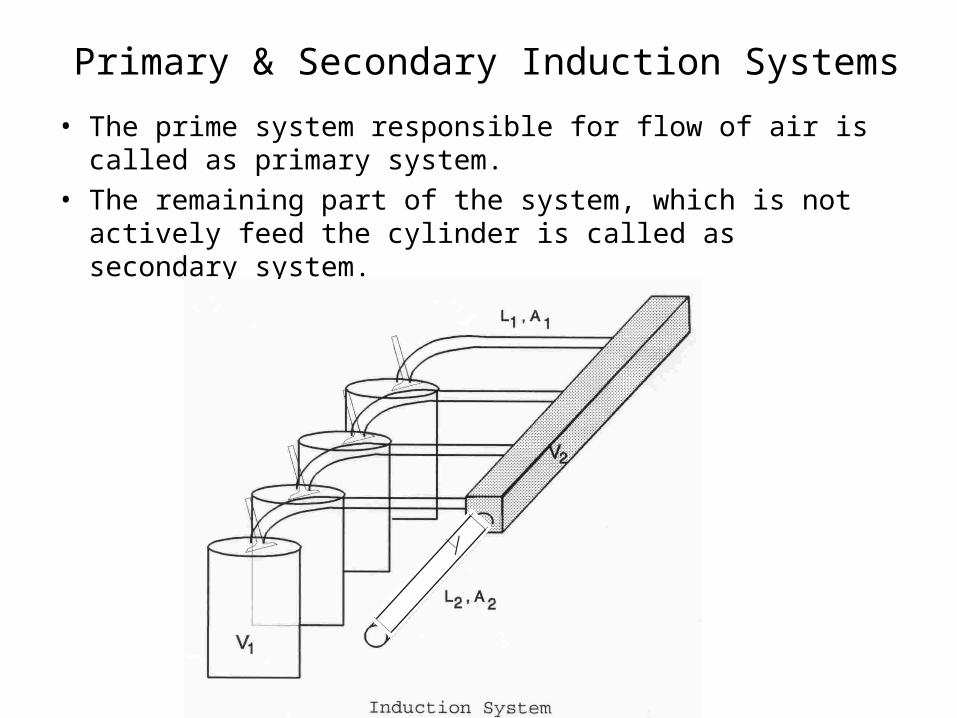
Primary & Secondary Induction Systems
• The prime system responsible for flow of air is called as primary system.
• The remaining part of the system, which is not actively feed the cylinder is called as secondary system.
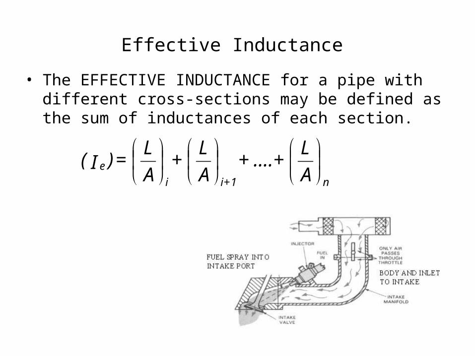
Effective Inductance
• The EFFECTIVE INDUCTANCE for a pipe with different cross-sections may be defined as the sum of inductances of each section.
A
L + .... +
A
L +
A
L = )I(
n1+ii
e
• INDUCTANCE RATIO (a)
ALAL
= a
1
2
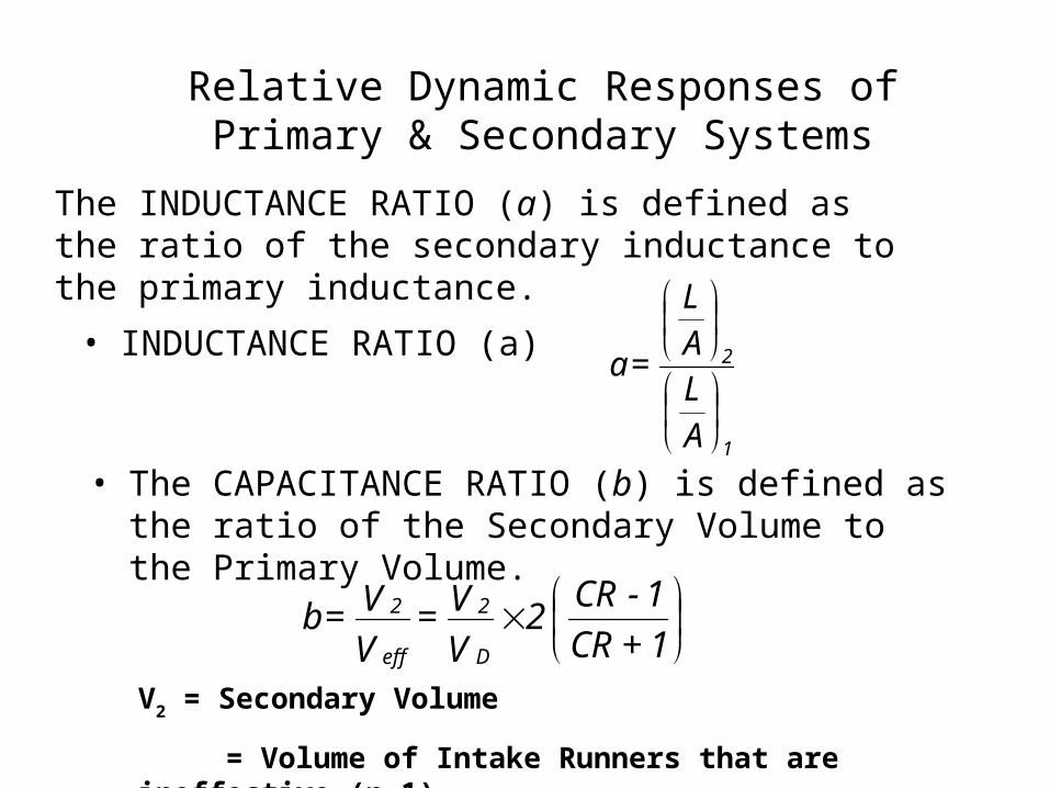
Relative Dynamic Responses of Primary & Secondary Systems
1 + CR
1 - CR 2
V
V =V
V = bD
2
eff
2
V2 = Secondary Volume
= Volume of Intake Runners that are ineffective (n-1)
• The CAPACITANCE RATIO (b) is defined as the ratio of the Secondary Volume to the Primary Volume.
The INDUCTANCE RATIO (a) is defined as the ratio of the secondary inductance to the primary inductance.
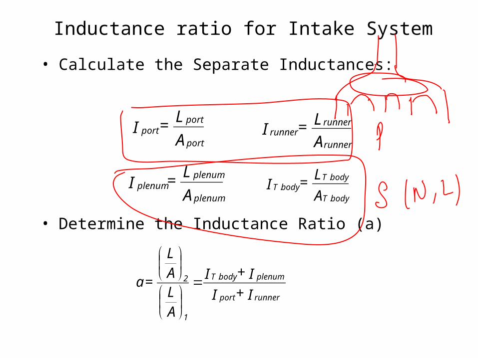
• Calculate the Separate Inductances:
Inductance ratio for Intake System
A
L = Iport
portport
A
L = Irunner
runnerrunner
A
L = Iplenum
plenumplenum
A
L = IbodyT
bodyTbodyT
.
..
I + I
I + I
ALAL
= arunnerport
plenumbodyT
1
2 .
• Determine the Inductance Ratio (a)

• Determine the Capacitance Ratio (b)
V 1)-(nV
= brunner
eff
V )(IND b a 2
B - A
2
1 = f
eff11 V )(IND b a 2
B + A
2
1 = f
eff12
b a 4 - )1 + a + b (a = B1) + a + b (a = A 2
(IND)1 = Inductance of the primary length
(IND)1 = Iport + Irunner
• Determine the Induction system Resonances
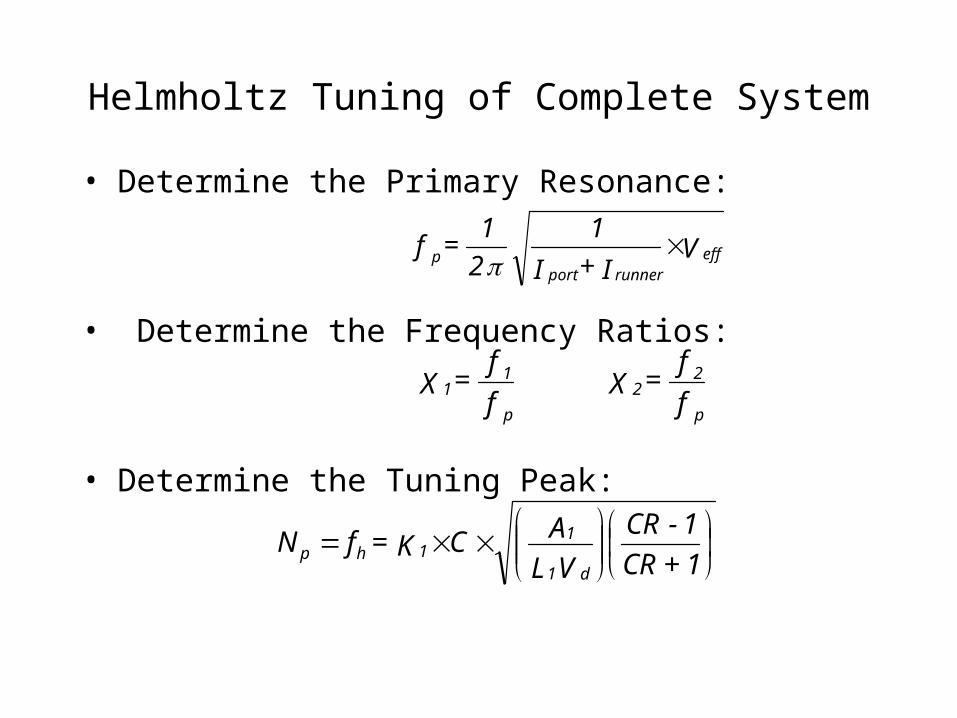
• Determine the Primary Resonance:
• Determine the Frequency Ratios:
• Determine the Tuning Peak:
Helmholtz Tuning of Complete System
V I + I
1
2
1 = f eff
runnerportp
f
f = X
f
f = X
p
22
p
11
1 + CR
1 - CR
V L
A C K = fNd1
11hp
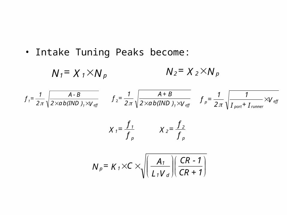
• Intake Tuning Peaks become:
N X = N p11 N X = N p22
V )(IND b a 2
B - A
2
1 = f
eff11 V )(IND b a 2
B + A
2
1 = f
eff12 V I + I
1
2
1 = f eff
runnerportp
f
f = X
f
f = X
p
22
p
11
1 + CR
1 - CR
V L
A C K = Nd1
11p

• A combined equation is possible indicating it’s 2nd order
PV4
1+CR1-CR
VV2
effP
4-1+effP
+1+CR1-CR
VV2
effP+1+
effP
+1+CR1-CR
VV2
effP
)C77(=N2
D
2
d
2
2
d
2
2
1
S1,2
A
L = P
2
A
L = EFF
eff
1)-(NC* A* )L+ L( = V mportman2
* s b* 4
= V 2d
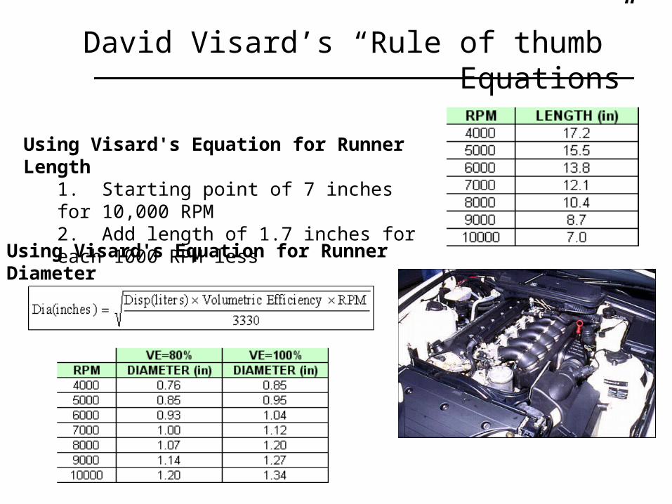
David Visard’s “Rule of thumb” Equations
Using Visard's Equation for Runner Length1. Starting point of 7 inches for 10,000 RPM2. Add length of 1.7 inches for each 1000 RPM less
Using Visard's Equation for Runner Diameter

More Ideas for Enhancing the Flow

Selection of Valve Timing for Better Flow

Stages of Valve Lifting
when the inlet valve opens, a rarefaction wave is sent upstream from the valve. When this wave encounters a change in area such as the intake manifold, a compression wave is generated and sent downstream back to the inlet valve. This compression wave increases the local density of the inlet flow, a process called the "ram effect".

Valve Lift Curves

Pseudo Flow Velocity
• Pseudo Flow Velocity is a parameter to study the effect of valve geometry and the rate change of cylinder volume on air flow into cylinder.
• PFV is the ratio of rate of change of cylinder volume to instantaneous minimum valve flow area.
d
ds
A
B
d
dV
APFV
mm 4
1 2
1
sin
cos
4
sin122
2
RA
aB
d
dV
APFV
mm

Flow Kinematics through Valves
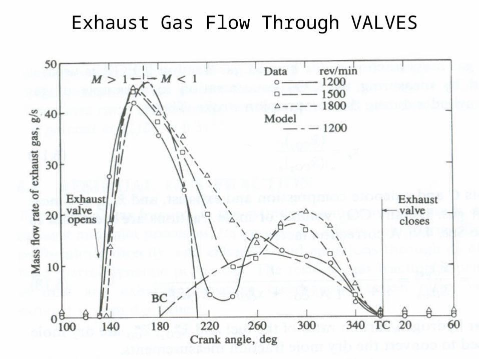
Exhaust Gas Flow Through VALVES

Measurements during Exhaust Stroke
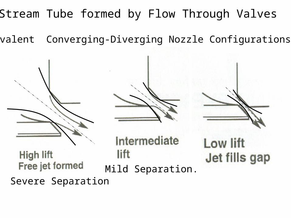
Stream Tube formed by Flow Through Valves
Equivalent Converging-Diverging Nozzle Configurations:
Mild Separation.Severe Separation
Strategies to Maximize Intake Air Quantity
• Most decent heads will have an equivalent flow through the valve area as a unrestricted port of about 80% of the valve area, this is if the camshaft it matched to the heads.
• Some well ported race heads may have an actual flow of an area up to 85%, but for the most part it is around 78-80%.
• To further help fill the cylinder, it helps to have a high velocity at the back of the valve.
• To do this the intake port can be tapered.
• To be effective, there should be between 1.7 and 2.5% increase in intake runner area per inch of runner, which represents a 1-1.5 degree taper.
Mas
s of
Fre
sh a
ir :I
ntak
e P
roce
ss
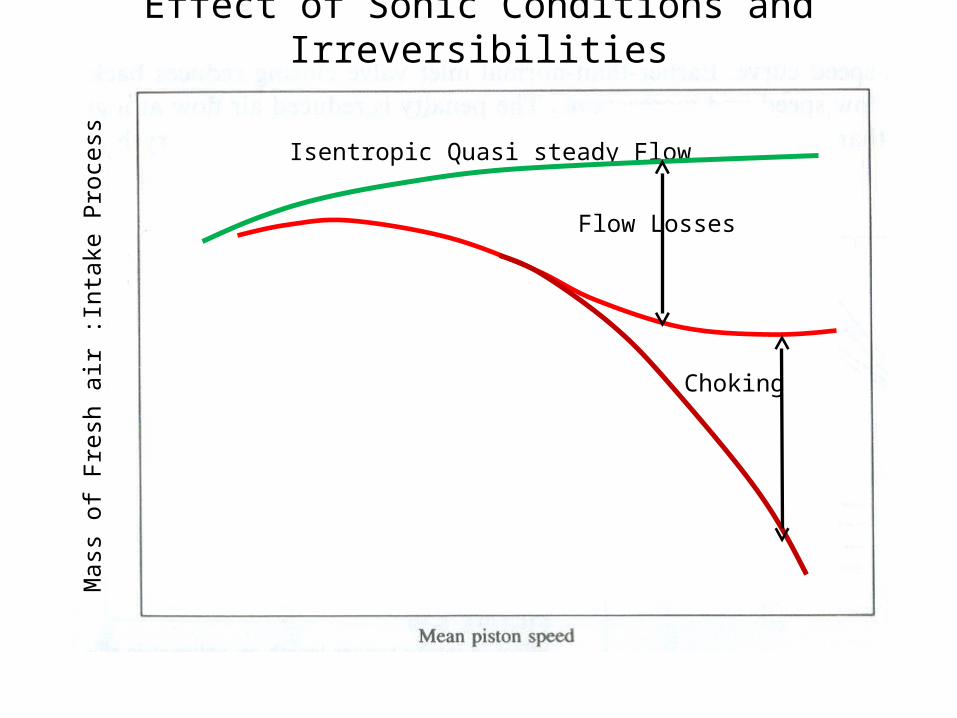
Effect of Sonic Conditions and Irreversibilities
Isentropic Quasi steady Flow
Flow Losses
Choking