Embed Size (px)
Citation preview
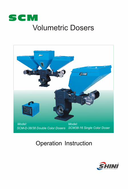
Volumetric DosersSCM
Operation Instruction
Model: SCM38-16 Single Color DoserSCM-D-38/38 Double Color Dosers
Model:

Contents
1. General Description ---------------------------------------------------------------
-----------------
--------------------------------------------
--------------------------------------------------
------------------------------------------------------
-------------------------------------------------
Contents
6. Maintenance and Repair
5. Trouble-shooting
4. Application and Operation
3. Installation and Debugging
2. Structure Characteristics and Working Principle
-------------------------------------------------Addenda
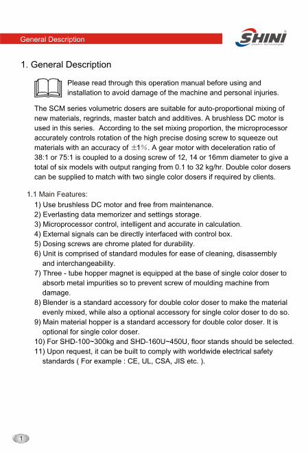
1. General Description
Please read through this operation manual before using and
installation to avoid damage of the machine and personal injuries.
General Description
1.1 Main Features:
The SCM series volumetric dosers are suitable for auto-proportional mixing of
new materials, regrinds, master batch and additives. A brushless DC motor is
used in this series. According to the set mixing proportion, the microprocessor
accurately controls rotation of the high precise dosing screw to squeeze out
materials with an accuracy of 1 . A gear motor with deceleration ratio of
38:1 or 75:1 is coupled to a dosing screw of 1 2, 14 or 16mm diameter to give a
total of six models with output ranging from 0.1 to 32 kg/hr. Double color dosers
can be supplied to match with two single color dosers if required by clients.
1) Use brushless DC motor and free from maintenance.
2) Everlasting data memorizer and settings storage.
3) Microprocessor control, intelligent and accurate in calculation.
4) External signals can be directly interfaced with control box.
5) Dosing screws are chrome plated for durability.
6) Unit is comprised of standard modules for ease of cleaning, disassembly
and interchangeability.
7) Three - tube hopper magnet is equipped at the base of single color doser to
absorb metal impurities so to prevent screw of moulding machine from
damage.
8) Blender is a standard accessory for double color doser to make the material
evenly mixed, while also a optional accessory for single color doser to do so.
9) Main material hopper is a standard accessory for double color doser. It is
optional for single color doser.
10) For SHD-100~300kg and SHD-160U~450U, floor stands should be selected.
11) Upon request, it can be built to comply with worldwide electrical safety
standards ( For example : CE, UL, CSA, JIS etc. ).

All service work should be carried out by a person with technical training or
corresponding professional experience. The manual contains instructions for
both handling and servicing. Chapter 7, which contains service instructions
intended for service engineers. Other chapters contain instructions for the
daily operator.
Any modifications of the machine must be approved by SHINI in order to
avoid personal injury and damage to machine. We shall not be liable for any
damage caused by unauthorized change of the machine.
Our company provides excellent after-sales service. Should you have any
problem during using the machine, please contact the company or the local
vendor.
Headquarter and Taipei factory
Tel: 0800-000-860
General Description
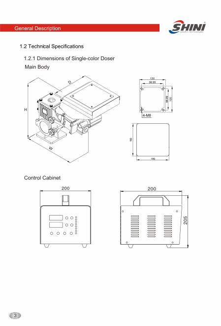
1.2 Technical Specifications
General Description
1.2.1 Dimensions of Single-color Doser
Main Body
Control Cabinet
150
150
4-M8
98
.99
98.99
12
0
120
General Description
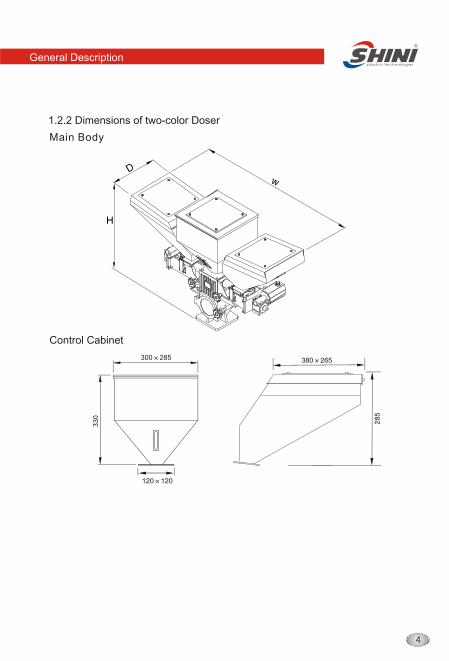
1.2.2 Dimensions of two-color Doser
Main Body
Control Cabinet
33
0
300 285
General Description
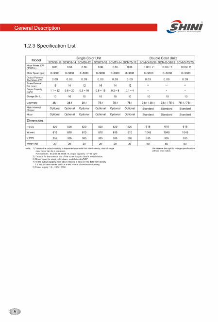
1.2.3 Specification List
Storage Bin (L)
Gear Ratio
Output Capacity (kg/hr)
Note 1) *means the output capacity is depended on model that client selecty, data of single
color doser can be a reference. For example SCM-D-38-16/38-14, output capacity 1.7~52 kg/hr.
2) **stands for the external dia. of the screw is up to client's model choice.
) All the output capacity from above models is base on the data from 1.2 ,dia.2~3mm master batch in a test criteria of continuous running. 5) Power supply: 1 , 230V, 50Hz.
3) Mount mixer for single color doser, model denotes"MS". 4 density
Mixer Optional Optional Optional Optional Optional Optional
Main Material Hopper
Optional StandardOptional Optional Optional Optional Optional
Standard
Standard
Standard
Standard
Standard
Weight (kg)
Dimensions
Model
10
38:1
1.1 ~ 32
10
75:1
0.5 ~ 15
10
0.6 ~ 20
38:1
10
0.3 ~ 10
38:1
10
0.2 ~ 8
75:1
10
0.1 ~ 4
75:1
10
38:1 / 38:1
*
10
38:1 / 75:1
*
10
75:1 / 75:1
*
335 335 335 335 335 335
29 29 29 29 29 29
615 615 615
335 335 335
1045 1045 1045
50 50 50
520 520 520 520 520 520
610 610 610 610 610 610
SCM38-16 SCM75-16SCM38-14 SCM38-12 SCM75-14 SCM75-12 SCM-D-38/38 SCM-D-38/75 SCM-D-75/75
We reserve the right to change specificationswithout prior notice.
Motor Power (kW)(50/60Hz)
Motor Speed (rpm) 0~3000 0~30000~3000 0~3000 0~3000 0~3000 0~3000 0~3000 0~3000
0.06 0.06 20.06 0.06 0.06 0.06 0.06 0.06 2 0.06 2
Output Power of The Mixer (kW) 0.09 0.09 0.09 0.090.090.090.090.090.09
Screw External Dia. (mm) 16 1614 12 14 12 ** ** **
General Description
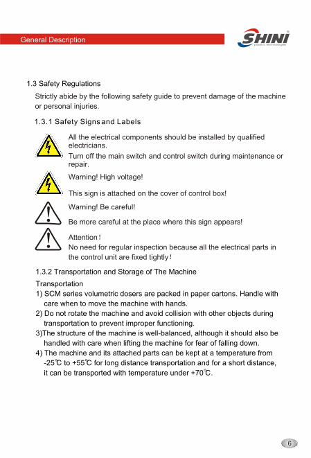
1.3 Safety Regulations
1.3.1 Safety Signs and Labels
1.3.2 Transportation and Storage of The Machine
Strictly abide by the following safety guide to prevent damage of the machine
or personal injuries.
All the electrical components should be installed by qualified electricians.
Turn off the main switch and control switch during maintenance or repair.
Warning! High voltage!
This sign is attached on the cover of control box!
Warning! Be careful!
Be more careful at the place where this sign appears!
Attention
No need for regular inspection because all the electrical parts in
the control unit are fixed tightly
Transportation
1) SCM series volumetric dosers are packed in paper cartons. Handle with
care when to move the machine with hands.
2) Do not rotate the machine and avoid collision with other objects during
transportation to prevent improper functioning.
3)The structure of the machine is well-balanced, although it should also be
handled with care when lifting the machine for fear of falling down.
4) The machine and its attached parts can be kept at a temperature from
-25 to +55 for long distance transportation and for a short distance,
it can be transported with temperature under +70 .

Storage
1) SCM series volumetric dosers should be stored indoors with temperature O O kept from 5 C to 40 C and humidity below 80%.
2) Disconnect all power supply and turn off main switch and control switch.
3) Keep the whole machine, especially the electrical components away from
water to avoid potential troubles caused by the water.
4) Plastic film should be used to protect the machine from dust and rains.
Working environment
The machine should be operated:
1) Indoors in a dry environment with max. temperature +45 and humidity no
more than 80%.
Do not use the machine:
1) If it is with a damaged cord.
2) On a wet floor or when it is exposed to rain to avoid electrical shock.
3) If it has been dropped or damaged until it is checked or fixed by a qualified
serviceman.
4) This equipment works normally in the environment with altitude within
3000m.
5) At least a clearance of 1m surrounding the equipment is required during
operation. Keep this equipment away from flammable sources at least two
meters.
6) Avoid vibration, magnetic disturbance at the operation area.
Rejected parts disposal
When the equipment has run out its life time and can not be used any more,
unplug the power supply and dispose of it properly according to local code.
In the event of loss or damage to a key of a trapped key interlocking device,
the complete key lock unit shall be replaced.
In case of fire, Co dry powder fire extinguisher should be applied. 2
Fire hazard
Feeding strip materials can give rise to an entanglement hazard.
General Description
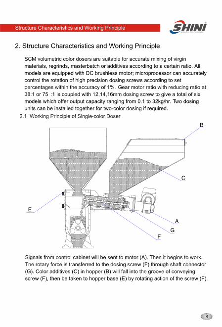
2. Structure Characteristics and Working Principle
2.1
Working Principle of Single-color Doser
SCM volumetric color dosers are suitable for accurate mixing of virgin
materials, regrinds, masterbatch or additives according to a certain ratio. All
models are equipped with DC brushless motor; microprocessor can accurately
control the rotation of high precision dosing screws according to set
percentages within the accuracy of 1% . G ear motor ratio with reducing ratio at
38:1 or 75 :1 is coupled with 12,14,16mm dosing screw to give a total of six
models which offer output capacity ranging from 0.1 to 32kg/hr. Two dosing
units can be installed together for two-color dosing if required.
Signals from control cabinet will be sent to motor (A). Then it begins to work.
The rotary force is transferred to the dosing screw (F) through shaft connector
(G). Color additives (C) in hopper (B) will fall into the groove of conveying
screw (F), then be taken to hopper base (E) by rotating action of the screw (F).
Structure Characteristics and Working Principle
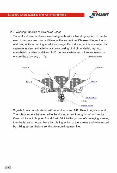
2.2 Working Principle of Two-color Doser
Hopper AHopper B
Itermediate hopper
Motor A
Shaft connector
Screw
Blending system
Motor B
Two-color doser combines two dosing units with a blending system. It can be
used to convey two color additives at the same time. Choose different kinds
of dosing units according to additive usage. Each dosing unit is controlled by
separate system, suitable for accurate dosing of virgin material, regrind,
materbatch or other additives. P.I.D. control system and microprocessor can
ensure the accuracy of 1%.
Signals from control cabinet will be sent to motor A/B. Then it begins to work.
The rotary force is transferred to the dosing screw through shaft connector.
Color additives in hopper A and B will fall into the groove of conveying screws,
then be taken to hopper base by rotating action of the screws and to be mixed
by mixing system before sending to moulding machine.
Structure Characteristics and Working Principle
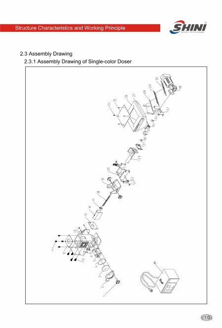
2.3 Assembly Drawing
2.3.1 Assembly Drawing of Single-color Doser
Structure Characteristics and Working Principle
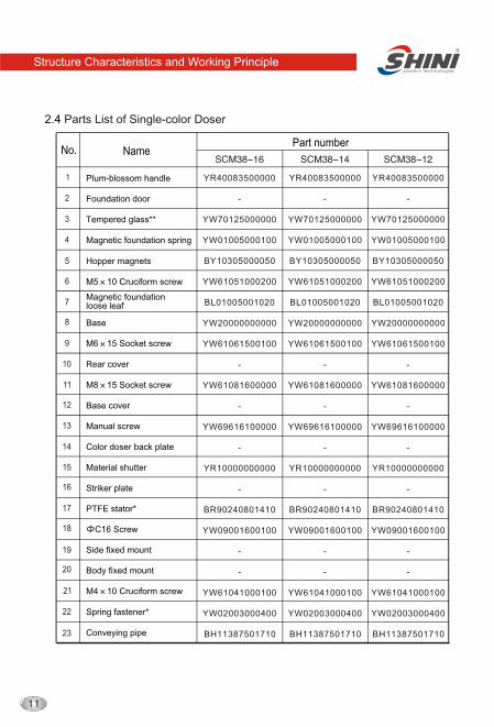
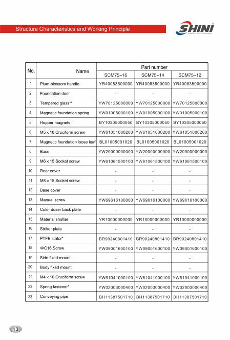
2.4 Parts List of Single-color Doser
Part numberName
1
2
3
4
5
6
7
8
9
10
11
12
13
14
15
16
17
18
19
20
21
22
23
Plum-blossom handle
Foundation door
Tempered glass**
Magnetic foundation spring
Hopper magnets
M5 10 Cruciform screw
Magnetic foundationloose leaf
Base
M6 15 Socket screw
Rear cover
M8 15 Socket screw
Base cover
Manual screw
Color doser back plate
Material shutter
PTFE stator*
C16 Screw
Side fixed mount
Body fixed mount
Spring fastener*
Conveying pipe
Striker plate
M4 10 Cruciform screw
Structure Characteristics and Working Principle
YR40083500000
-
YW70125000000
YW01005000100
BY10305000050
YW61051000200
BL01005001020
YW20000000000
YW61061500100
-
YW61081600000
-
YW69616100000
-
YR10000000000
-
BR90240801410
YW09001600100
-
-
YW61041000100
YW02003000400
BH11387501710
YR40083500000
-
YW70125000000
YW01005000100
BY10305000050
YW61051000200
BL01005001020
YW20000000000
YW61061500100
-
YW61081600000
-
YW69616100000
-
YR10000000000
-
BR90240801410
YW09001600100
-
-
YW61041000100
YW02003000400
BH11387501710
YR40083500000
-
YW70125000000
YW01005000100
BY10305000050
YW61051000200
BL01005001020
YW20000000000
YW61061500100
-
YW61081600000
-
YW69616100000
-
YR10000000000
-
BR90240801410
YW09001600100
-
-
YW61041000100
YW02003000400
BH11387501710
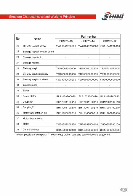
24
25
26
27
28
29
30
31
32
33
34
35
36
37
38
39
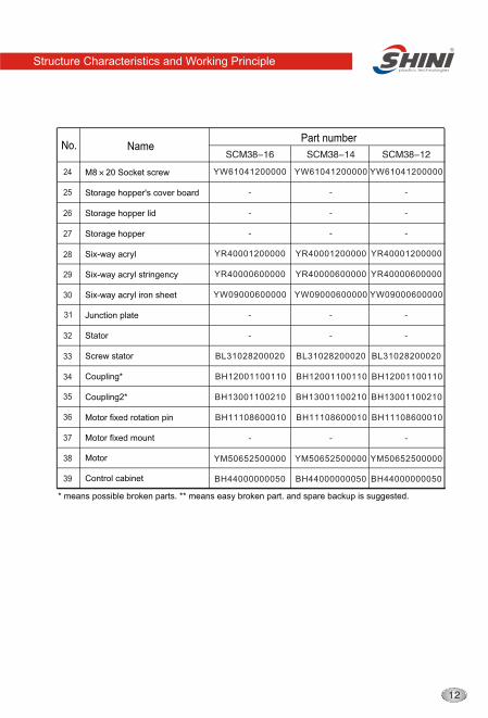
M8 20 Socket screw
Storage hopper's cover board
Storage hopper lid
Storage hopper
Six-way acryl
Six-way acryl stringency
Six-way acryl iron sheet
Junction plate
Stator
Screw stator
Coupling*
Coupling2*
Motor fixed rotation pin
Motor fixed mount
Motor
Control cabinet
Part numberName
* means possible broken parts. ** means easy broken part. and spare backup is suggested.
Structure Characteristics and Working Principle
YW61041200000
-
-
-
YR40001200000
YR40000600000
YW09000600000
-
-
BL31028200020
BH12001100110
BH13001100210
BH11108600010
-
BH44000000050
YW61041200000
-
-
-
YR40001200000
YR40000600000
YW09000600000
-
-
BL31028200020
BH12001100110
BH13001100210
BH11108600010
-
BH44000000050
YW61041200000
-
-
-
YR40001200000
YR40000600000
YW09000600000
-
-
BL31028200020
BH12001100110
BH13001100210
BH11108600010
-
BH44000000050
YM50652500000 YM50652500000 YM50652500000
1
2
3
4
5
6
7
8
9
10
11
12
13
14
15
16
17
18
19
20
21
22
23
Part numberName
Plum-blossom handle
Foundation door
Tempered glass**
Magnetic foundation spring
Hopper magnets
M5 10 Cruciform screw
Magnetic foundation loose leaf
Base
M6 15 Socket screw
Rear cover
M8 15 Socket screw
Base cover
Manual screw
Color doser back plate
Material shutter
PTFE stator*
C16 Screw
Side fixed mount
Body fixed mount
Spring fastener*
Conveying pipe
Striker plate
M4 10 Cruciform screw
Structure Characteristics and Working Principle
YR40083500000
-
YW70125000000
YW01005000100
BY10305000050
YW61051000200
BL01005001020
YW20000000000
YW61061500100
-
-
-
YW69616100000
-
YR10000000000
-
BR90240801410
YW09001600100
-
-
YW61041000100
YW02003000400
BH11387501710
YR40083500000
-
YW70125000000
YW01005000100
BY10305000050
YW61051000200
BL01005001020
YW20000000000
YW61061500100
-
-
-
YW69616100000
-
YR10000000000
-
BR90240801410
YW09001600100
-
-
YW61041000100
YW02003000400
BH11387501710
YR40083500000
-
YW70125000000
YW01005000100
BY10305000050
YW61051000200
BL01005001020
YW20000000000
YW61061500100
-
-
-
YW69616100000
-
YR10000000000
-
BR90240801410
YW09001600100
-
-
YW61041000100
YW02003000400
BH11387501710
* means possible broken parts. ** means easy broken part. and spare backup is suggested.
24
25
26
27
28
29
30
31
32
33
34
35
36
37
38
39
Part numberName
M8 20 Socket screw
Storage hopper's cover board
Storage hopper lid
Storage hopper
Six-way acryl
Six-way acryl stringency
Six-way acryl iron sheet
Junction plate
Stator
Screw stator
Coupling*
Coupling2*
Motor fixed rotation pin
Motor fixed mount
Motor
Control cabinet
Structure Characteristics and Working Principle
YW61041200000
-
-
-
YR40001200000
YR40000600000
YW09000600000
-
-
BL31028200020
BH12001100110
BH13001100210
BH11108600010
-
YM50652500100
BH44000000050
YW61041200000
-
-
-
YR40001200000
YR40000600000
YW09000600000
-
-
BL31028200020
BH12001100110
BH13001100210
BH11108600010
-
BH44000000050
YW61041200000
-
-
-
YR40001200000
YR40000600000
YW09000600000
-
-
BL31028200020
BH12001100110
BH13001100210
BH11108600010
-
BH44000000050
YM50652500100 YM50652500100
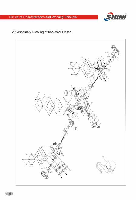
2.5 Assembly Drawing of two-color Doser
Structure Characteristics and Working Principle
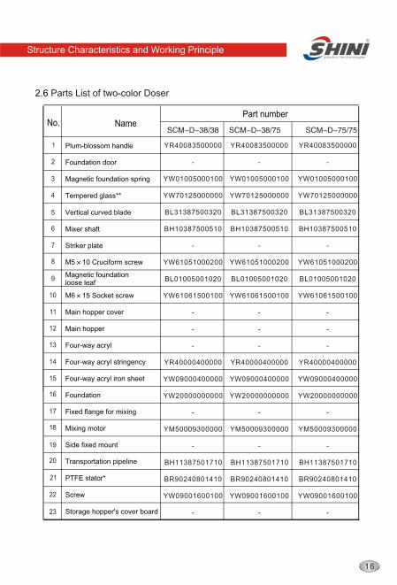
2.6 Parts List of two-color Doser
1
2
3
4
5
6
7
8
9
10
11
12
13
14
15
16
17
18
19
20
21
22
23
Plum-blossom handle
Foundation door
Magnetic foundation spring
Tempered glass**
Vertical curved blade
Mixer shaft
Striker plate
M5 10 Cruciform screw
Magnetic foundation loose leaf
M6 15 Socket screw
Main hopper cover
Main hopper
Four-way acryl
Four-way acryl stringency
Four-way acryl iron sheet
Fixed flange for mixing
Mixing motor
Side fixed mount
Transportation pipeline
Screw
Storage hopper's cover board
Foundation
PTFE stator*
Part numberName
Structure Characteristics and Working Principle
YR40083500000
-
YW01005000100
YW70125000000
BL31387500320
BH10387500510
-
YW61051000200
BL01005001020
YW61061500100
-
-
-
YR40000400000
YW09000400000
YW20000000000
-
YM50009300000
-
BH11387501710
BR90240801410
YW09001600100
-
YR40083500000
-
YW01005000100
YW70125000000
BL31387500320
BH10387500510
-
YW61051000200
BL01005001020
YW61061500100
-
-
-
YR40000400000
YW09000400000
YW20000000000
-
YM50009300000
-
BH11387501710
BR90240801410
YW09001600100
-
YR40083500000
-
YW01005000100
YW70125000000
BL31387500320
BH10387500510
-
YW61051000200
BL01005001020
YW61061500100
-
-
-
YR40000400000
YW09000400000
YW20000000000
-
YM50009300000
-
BH11387501710
BR90240801410
YW09001600100
-
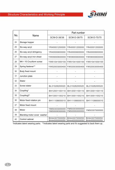
*Indicates latent wearing parts **Indicates latent wearing parts and it's suggested to back them up.
24
25
26
27
28
29
30
31
32
33
34
35
36
37
38
39
40
Storage hopper
Six-way acryl
Six-way acryl stringency
Six-way acryl iron sheet
M4 10 Cruciform screw
Spring fastener**
Body fixed mount
Junction plate
Stator
Screw stator
Coupling*
Coupling *2
Motor fixed rotation pin
Motor fixed mount
Motor
Blending motor cover washer
Control cabinet
SCM-D-38/38 SCM-D-38/75 SCM-D-75/75
Part numberName
Structure Characteristics and Working Principle
-
YR40001200000
YR40000600000
YW09000600000
YW61041000100
YW02003000400
-
-
-
BL31028200020
BH12001100110
BH13001100210
BH11108600010
-
-
YM50303000000YM50009300000
BH44307500050BH44000000050
-
YR40001200000
YR40000600000
YW09000600000
YW61041000100
YW02003000400
-
-
-
BL31028200020
BH12001100110
BH13001100210
BH11108600010
-
-
-
YR40001200000
YR40000600000
YW09000600000
YW61041000100
YW02003000400
-
-
-
BL31028200020
BH12001100110
BH13001100210
BH11108600010
-
-
YM50307500000YM50303000000YM50009300000
BH44307500050BH44000000050
BH44307500050BH44000000050
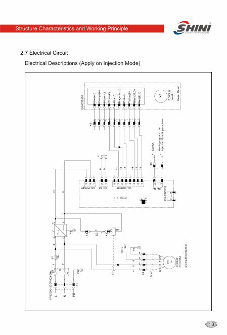
Electrical Descriptions (Apply on Injection Mode)
2.7 Electrical Circuit
1
X3
+ -M
elt
ing
sig
na
l of th
eIn
jecti
on
Mo
uld
ing
ma
ch
ine
24
VD
C
12
3
J3
1.5
mm
2
PE
V+
V-
54
2
3
4
7 6 5 4 3 2 11
6
15
14
11
13
12
98
2356478910
L N
UF
1S
1
V+ V-
BG
65
X5
0S
1
0.0
65
kW
In=
4A
Do
se
r M
oto
r
M2
PE
PE
5A
1
X4
U2
C 5u
F
CN-POWER
2 1
CN-INJ
PE
X1
L N
2
1CN
-PR
ES
S2
13 2 1
CN-BZ
8
CN-MOTOR
1
X2
H
6
213
Mix
ing
Mo
tor(
op
tio
n)
Re
d(E
,F)
Blo
wn
(L)
Bla
ck(M
,G)
Ye
llo
w(B
)
Pin
k(J
)
Ma
ge
nta
(H)
Gre
en
(D)
Ora
ng
e(A
)
Blu
e(C
)
Wh
ite
(K)
2
X5
X5
7
S2
A2A1
A1(SV-01
K1
PE
Z1
U1
1~
0.0
9kW
In=
0.9
5A
M1
2
1/P
E/2
00
~2
30
V 5
0/6
0H
z
Structure Characteristics and Working Principle
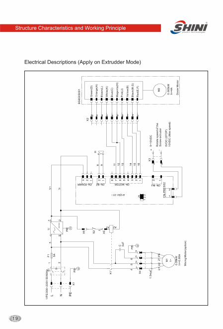
Electrical Descriptions (Apply on Extrudder Mode)
BG
65
X5
0S
1
0.0
65
kW
In=
4A
Do
se
r M
oto
r
M2
1
X2
Re
d(E
,F)
Blo
wn
(L)
Bla
ck(M
,G)
Ye
llo
w(B
)
Pin
k(J
)
Ma
ge
nta
(H)
Gre
en
(D)
Ora
ng
e(A
)
Blu
e(C
)
Wh
ite
(K)
2356478910
16
15
14
11
13
12
H
6
213
Mix
ing
Mo
tor(
op
tio
n)
1.5
mm
2
PE
V+
V-
54
7 6 5 4 3 2 1
98
21
X3
+ -
0V
DC
:(S
TO
P)
10
VD
C:(
Ma
x sp
ee
d)
0~
10
VD
C
Ro
tate
sp
ee
d o
f th
eS
cre
w e
xtr
ud
er
12
3
J3
1
X4
2
3
4
X5
X5
7
S2
A2A1
A1(SV-01
K1
PE
Z1
U1
1~
0.0
9kW
In=
0.9
5A
M1
2
1/P
E/2
00
~2
30
V 5
0/6
0H
z
L N
UF
1S
1
V+ V-
PE
PE
5A
U2
C 5u
F
CN-POWER
2 1
CN-INJ
PE
X1
L N
2
1CN
-PR
ES
S2
13 2 1
CN-BZ
8
CN-MOTOR
Structure Characteristics and Working Principle
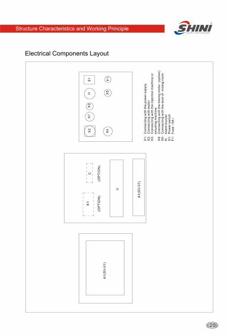
Electrical Components Layout
X1
Co
nn
ecti
ng
wit
h t
he
po
we
r su
pp
ly
X2
Co
nn
ecti
ng
wit
h m
oto
rX
3C
on
ne
cti
ng
wit
h t
he
in
jecti
on
ma
ch
ine
or
e
xtu
din
g m
ach
ine
X4
Co
nn
ecti
ng
wit
h t
he
mix
ing
mo
tor
(o
pti
on
)X
5C
on
ne
cti
ng
wit
h t
he
do
or
of m
ixin
g r
oo
m
H A
larm
bu
zze
rS
1P
ow
er
sw
itch
F1
Fu
se
5A
(OP
TIO
N)
(OP
TIO
N)
U
X2
S1
A1
(SV
-01
)
X1
X3
H
X4
F1
X5
K1
A1
(SV
-01
)
C
Structure Characteristics and Working Principle
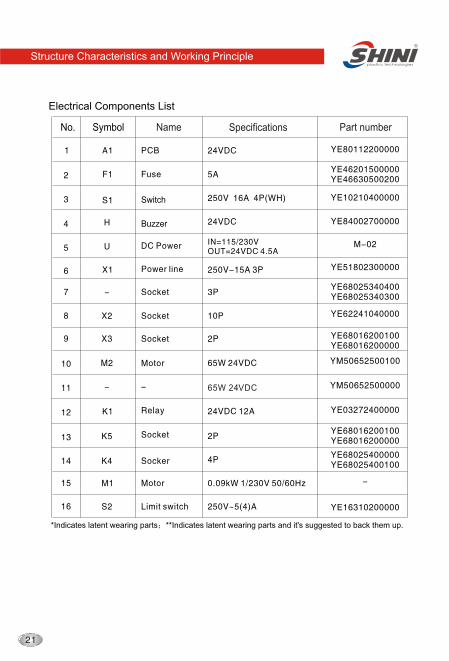
Electrical Components List
*Indicates latent wearing parts **Indicates latent wearing parts and it's suggested to back them up.
Switch
65W 24VDC
No. Symbol Name Specifications Part number
Buzzer
Structure Characteristics and Working Principle
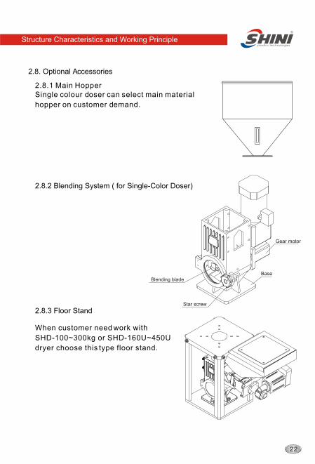
2.8. Optional Accessories
2.8.2 Blending System ( for Single-Color Doser)
Single colour doser can select main material
hopper on customer demand.
2.8.1 Main Hopper
Base
Star screw
Blending blade
Gear motor
2.8.3 Floor Stand
When customer need work with
SHD-100~300kg or SHD-160U~450U
dryer choose this type floor stand.
Structure Characteristics and Working Principle
Installation and Debugging
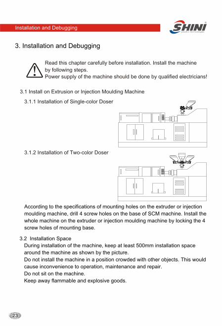
3. Installation and Debugging
Read this chapter carefully before installation. Install the machine
by following steps.
Power supply of the machine should be done by qualified electricians!
3.1 Install on Extrusion or Injection Moulding Machine
According to the specifications of mounting holes on the extruder or injection
moulding machine, drill 4 screw holes on the base of SCM machine. Install the
whole machine on the extruder or injection moulding machine by locking the 4
screw holes of mounting base.
3.1.1 Installation of Single-color Doser
3.1.2 Installation of Two-color Doser
3.2 Installation Space
During installation of the machine, keep at least 500mm installation space
around the machine as shown by the picture.
Do not install the machine in a position crowded with other objects. This would
cause inconvenience to operation, maintenance and repair.
Do not sit on the machine.
Keep away flammable and explosive goods.
Installation and Debugging
500mm
500mm
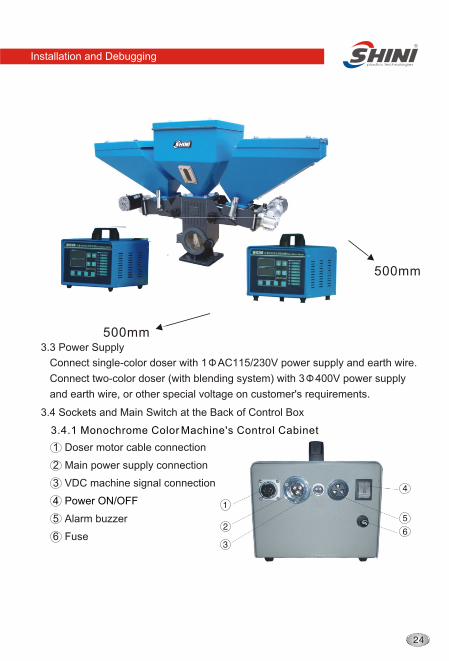
3.4 Sockets and Main Switch at the Back of Control Box
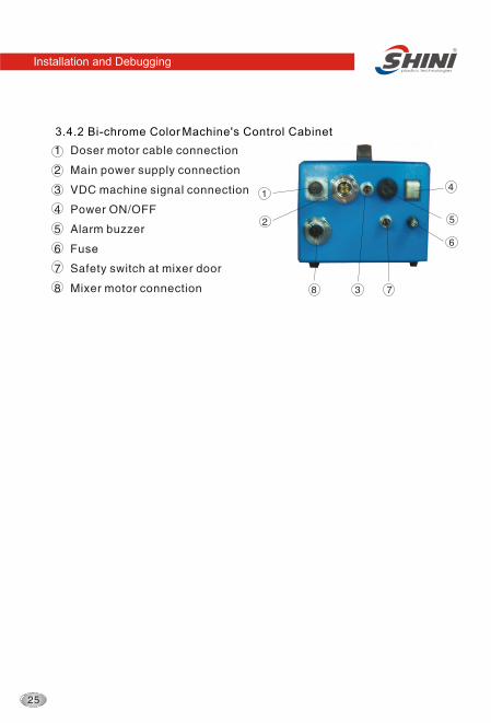
1 Doser motor cable connection
2 Main power supply connection
3 VDC machine signal connection
4 Power ON/OFF
5 Alarm buzzer
6 Fuse
Connect single-color doser with 1 AC115/230V power supply and earth wire.
Connect two-color doser (with blending system) with 3 400V power supply
and earth wire, or other special voltage on customer's requirements.
3.3 Power Supply
3.4.1 Monochrome Color Machine's Control Cabinet
Installation and Debugging
connection
connection
connection
Fuse
connection
3.4.2 Bi-chrome Color Machine's Control Cabinet
Application and Operation
4. Application and Operation
4.1 Control Panel:
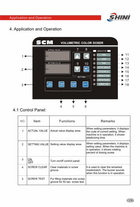
1 ACTUAL VALUE
When setting parameters, it displaysthe code of current setting. When machine is in operation, it shows plasticizing time.
2
Item
Functions Remarks NO.
Actual value display area.
SETTING VALUE Setting value display area. When setting parameters, it displays setting value. When the machine is in operation, it shows rotating percent of dosing screw.
3Turn on/off control panel.
1
2
3
11
12
13
14
15
16
17
18
4 5 6
ONOFF
7 8
9 10
4 SCREW CLEAR Clear materials in screw groove.
5 SCREW TEST For filling materials into screw groove for 50 sec. screw test.
It is used to clear the remainedmasterbatch. The buzzer sounds when this function is in operation.
Application and Operation
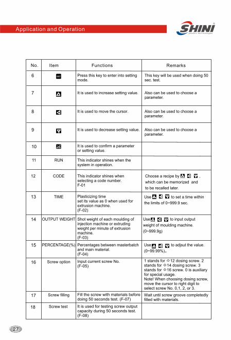
Item Functions Remarks No.
6 Press this key to enter into setting mode.
This key will be used when doing 50 sec. test.
11 RUN
12 CODE
7 It is used to increase setting value.
8
9
10 It is used to confirm a parameter or setting value.
It is used to move the cursor.
It is used to decrease setting value.
Also can be used to choose a parameter.
Also can be used to choose a parameter.
Also can be used to choose a parameter.
This indicator shines when the system in operation.
13 TIME
14 OUTPUT WEIGHT
15 PERCENTAGE(%)
This indicator shines when selecting a code number.F-01
Choose a recipe by ,
which can be memorized and
to be recalled later.
Plasticizing timeset its value as 0 when used for extrusion machine.(F-02)
Use to set a time within
the limits of 0~999.9 sec.
Shot weight of each moulding of injection machine or extruding weight per minute of extrusion machine.(F-03)
Use to input output
weight of moulding machine.
(0~999.9g)
Percentages between masterbatch and main material.(F-04)
Use to adjsut the value.
(0~99.99%)
SETSET
ENTERENTER
16 Screw option 1 stands for 12 dosing screw. 2 stands for 14 dosing screw. 3 stands for 16 screw. 0 is auxiliary for special usage.Note! When choosing dosing screw, move the cursor to right digit to select screw No. 0,1, 2, or 3.
17
Input current screw No.(F-05)
Screw filling Fill the screw with materials before doing 50 seconds test. (F-07)
Wait until screw groove completedlyfilled with materials.
18 Screw test It is used for testing screw output capacity during 50 seconds test. (F-08)
Application and Operation
4.2 Start/stop of the Machine
1. Check that the power is turned on.
2. Switch on the main switch at the back of control cabinet.
3. Press , the RUN indicator will become bright.
4. When there are signals fed into the machine, it operates accordingly.
5. Stop the machine in reverse steps.
4.3 Operation Guide
ONOFF
1. After the machine started, press for 3 seconds.
2. Choose a recipe when "CODE" indicator is bright. Use to adjust the
value of F-01, standing for recipe code. Press to confirm and enter next
setting.
3. Choose plasticizing time when "TIME" indicator is bright. Use to set
the value of F-02, standing for plasticizing time. Press to confirm
and enter next setting item.
4. Set shot weight or extruding weight when "OUTPUT WEIGHT" indicator
is bright. Use to adjust the value of F-03, standing for output weight
of moulding machine. Press to confirm and enter next setting.
SETSET
SETSET
SETSET
SETSET
SETSET
SETSET
The value of F-01 can be of any number from 0 to 49. So there
can be total 50 recipes. Setting the value of F-02 to F-06 acc
ording to the relative requirements in each recipe.
Note: set its value as 0 when it is used with extruders.
Note!
when it is used with extruders, the unit of output weight is g/min;
but when used with Injection machines, the unit is g/cycle.5. Set the percentage of color additive when "PERCENT" indicator is
bright. Use to adjust the value of F-04, standing for color additive
percentage. Press to confirm and enter next setting.
6. Choose a dosing screw when "OPTION" indicator is bright. Use to
choose the value of F-05, standing for dosing screw code No. Press
to confirm and enter next setting.
Application and Operation
Press at any step to finish the setting.ENTERENTER
Note: before using SCM series of machines, please set the
parameters of F-01~F-05. (For details of 50 seconds test, please
refer to 6.3. It's better to repeat this test for several times to get more
accurate average value of F-08. According the color of products,
adjust the percentage of color additives(the value of F-04) or the
value of F-09 (average of 50 seconds test). Refer to the following
data, set a proper value for F-09 or choose screw calibration value
for F-14 to F-22 (refer to 6.4 for details).
4. So if "g" (10g, 100g or kg) is used as the unit of F-03, then
use a corresponding unit for F-09.
1 stands for 12 dosing screw. 2 stands for 14 dosing screw.
3 stands for 16 screw. 0 is auxiliary for specially made screw.
Note! When choosing dosing screw, move the cursor to right digit
to select screw No. 0,1, 2, or 3.
7. Fill the screw groove with color additives when "FILLING" indicator is
bright. "ACTUAL VALUE " shows F-06.Test the output capacity of
dosing screw in 50 sconds. If you need not to do the test, press to
return to step 2 or press to complete parameter setting. If you need
to do the test, do it by following steps.
For accurate control of output capacity, it is strongly recommended
that you do 50 seconds test.
8. When "ACTUAL VALUE" shows F-06, press "SCREW TEST" for three
seconds to enter screw filling mode(F-07). Keep on pressing "SCREW
TEST" until the screw is full filled. Press to enter next step.
9. F-08 stands for the function of 50 seconds test of screw capacity. The
screw rotates for 50 seconds( use a container to collect the additives)
and then the machine enter F-09 automatically.
10. Use an electrical scale to weigh the materials collected in above step.
Use to input the weight as the value of F-09. Press to complete
the test.
Note: the unit of input weight should be the same with that used in
step
SETSET
ENTERENTER
SETSET
ENTERENTER
Application and Operation
Color additives Screw diameter(mm) Weight(g)
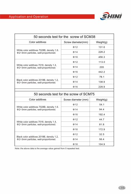
12 131.6
14
16 456.3
12 113.0
14
16 442.2
12 78.1
14
16 228.9
50 seconds test for the screw of SCM38
White color additives 7028B, density 1.6. 2~3mm particles, well-proportioned.
White color additves 7018, density 1.4, 2~3mm particles, well-proportioned.
Black color additives 2018B, density 1.2, 2~3mm particles, well-proportioned.
Color additives Screw diameter (mm) Weight(g)
12 54.1
14
16 192.4
12 44.7
14
16 172.9
12 32.5
14
16 104.9
50 seconds test for the screw of SCM75
Note: the above data is the average value gained from 5 repeated test.
56.4
138.9
205
228.2
94.4
81.8
White color additives 7028B, density 1.6. 2~3mm particles, well-proportioned.
White color additves 7018, density 1.4, 2~3mm particles, well-proportioned.
Black color additives 2018B, density 1.2, 2~3mm particles, well-proportioned.
Application and Operation
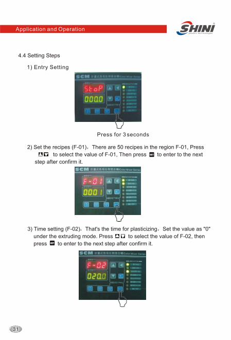
4.4 Setting Steps
1) Entry Setting
Press for 3 seconds
2) Set the recipes (F-01) There are 50 recipes in the region F-01, Press
to select the value of F-01, Then press to enter to the next
step after confirm it.
3) Time setting (F-02) That's the time for plasticizing Set the value as "0"
under the extruding mode. Press to select the value of F-02, then
press to enter to the next step after confirm it.
SETSET
SETSET
Application and Operation
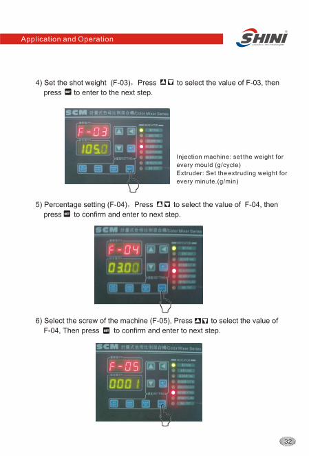
4) Set the shot weight (F-03) Press to select the value of F-03, then
press to enter to the next step.SETSET
Injection machine: set the weight for
every mould (g/cycle)
Extruder: Set the extruding weight for
every minute.(g/min)
5) Percentage setting (F-04) Press to select the value of F-04, then
press to confirm and enter to next step.SETSET
6) Select the screw of the machine (F-05), Press to select the value of
F-04, Then press to confirm and enter to next step.SETSET
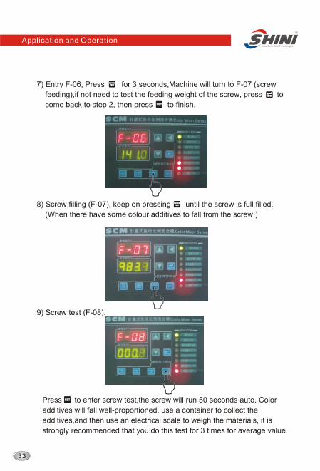
7) Entry F-06, Press for 3 seconds,Machine will turn to F-07 (screw
feeding),if not need to test the feeding weight of the screw, press to
come back to step 2, then press to finish.
SCREW TESTSCREW TEST
SETSET
ENTERENTER
8) Screw filling (F-07), keep on pressing until the screw is full filled.
(When there have some colour additives to fall from the screw.)
SCREW TESTSCREW TEST
9) Screw test (F-08).
Press to enter screw test,the screw will run 50 seconds auto. Color
additives will fall well-proportioned, use a container to collect the
additives,and then use an electrical scale to weigh the materials, it is
strongly recommended that you do this test for 3 times for average value.
SETSET
Application and Operation
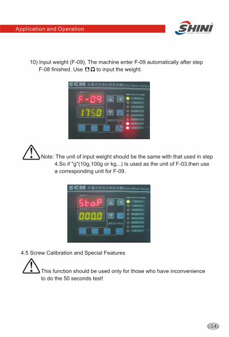
10) Input weight (F-09), The machine enter F-09 automatically after step
F-08 finished. Use to input the weight.
Note: The unit of input weight should be the same with that used in step
4.So if "g"(10g,100g or kg...) Is used as the unit of F-03,then use
a corresponding unit for F-09.
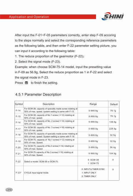
4.5 Screw Calibration and Special Features
This function should be used only for those who have inconvenience
to do the 50 seconds test!
Application and Operation
4.5.1 Parameter Description
Symbol Description Range Default
F-14
F-15
F-16
F-17
F-18
F-19
F-20
F-21
F-22
F-23*
For SCM-38, capacity of specially made screw rotating at
50% of max. speed. system setting is same with F-15.
For SCM-38, capacity of No.1 screw ( 12) rotating at
50% of max. speed.
For SCM-38, capacity of No. 2 screw( 14) rotating at
50% of max. speed.
For SCM-38, capacity of No. 3 screw( 16) rotating at
50% of max. speed.
For SCM-75, capacity of specially made screw rotating at
50% of max. speed. System setting is same with F-19.
For SCM-75, capacity of No.1 screw( 12) rotating at
50% of max. Speed.
For SCM-75, capacity of No.2 screw( 14) rotating at
50% of max. Speed.
For SCM-75 capacity of No.3 screw( 16) rotating at
50% of max. Speed.
Select a model: SCM-38 or SCM-75.
CYCLE input signal mode.
0-999.9g
0-999.9g
0-999.9g
0-999.9g
0-999.9g
0-999.9g
0-999.9g
0-999.9g
0: SCM-38
1: SCM-75
0: INPUT TIMER SYNC
1: INPUT ONLY
2: TIMER ONLY
78.1g
78.1g
138.9g
228.9g
32.5g
32.5g
56.4g
104.9g
0
0
After input the F-01~F-05 paremeters correctly, enter step F-09 accoring
to the steps normally and select the corresponding reference paremeters
as the following table, and then enter F-22 paremeter setting picture, you
can input it according to the following table:
1. The reduce proportion of the gearmotor (F-22)
2. Select the signal mode (F-23).
Example: when choose SCM-75-14 model, input the presetting value
in F-09 as 56.9g, Select the reduce proportion as 1 in F-22 and select
the signal mode in F-23.
Press to finish the setting.ENTERENTER
Application and Operation
Note:* 0---External signals & plasticizing time
1---External signals: the machine works according to external
signals.
2---Plasticizing time: the machine works according to the
plasticizing time.
Default value is 0. Under this working mode, screw conveying time
is decided by the shorter of external signals and plasticizing time.
i.e. When moulding cycle is less than set plasticizing time, SCM
stops. While if moulding cycle bigger than plasticizing time, SCM
stops operation as well.
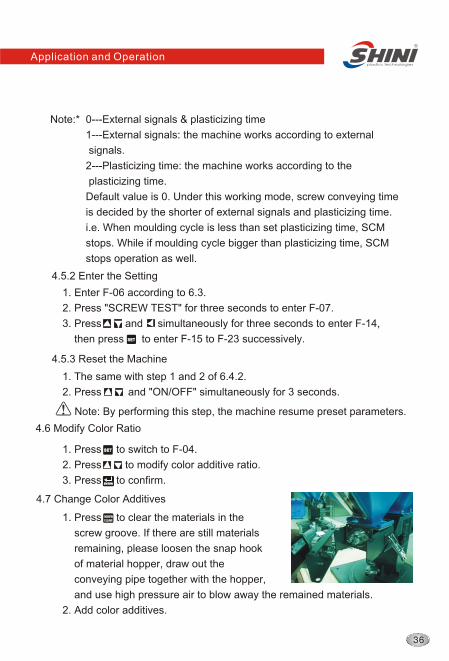
1. Press to clear the materials in the
screw groove. If there are still materials
remaining, please loosen the snap hook
of material hopper, draw out the
conveying pipe together with the hopper,
and use high pressure air to blow away the remained materials.
2. Add color additives.
4.6 Modify Color Ratio
1. Press to switch to F-04.
2. Press to modify color additive ratio.
3. Press to confirm.
SETSET
ENTERENTER
4.7 Change Color Additives
4.5.3 Reset the Machine
1. The same with step 1 and 2 of 6.4.2.
2. Press and "ON/OFF" simultaneously for 3 seconds.
Note: By performing this step, the machine resume preset parameters.
1. Enter F-06 according to 6.3.
2. Press "SCREW TEST" for three seconds to enter F-07.
3. Press and simultaneously for three seconds to enter F-14,
then press to enter F-15 to F-23 successively.
4.5.2 Enter the Setting
SETSET
Application and Operation

4.8 Replace Dosing Screws
1. Cut off power supply, loosen snap hook of hopper, draw out the hopper
and screw. Unlock the screw fastening
plate to remove the conveying screw for
replacement.
2. Install the screw and hopper back to the
machine.
Note: 12/14 screw is supplied with a sleeve.
Application and Operation
Trouble-shooting
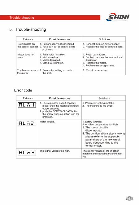
5. Trouble-shooting
Possible reasons Solutions
1. Parameter mistakes.2. Motor overload.3. Motor damaged.4. Signal wire broken.
1. Reset parameters.2. Contact the manufacturer or local distributor.3. Replace the motor.4. Replace motor signal wire.
Motor does notwork.
No indicates on the control cabinet.
1. Power supply not connected.2. Fuse burt out or control board problems.
Failures
1. Connect through power supply.2. Replace the fuse or control board.
The buzzer soundsthe alarm.
1. Parameter setting exceeds the limit.
1. Reset parameters.
1. The requested output capacity bigger then the machine's highest output capacity. 2. push the SCREW CLEAR button the screw cleaning action is in the progress.
Motor trouble. 1. Screw jammed.2. Ambient temperature too high.3. The motor circuit is disconnected.4. The configuration setup is wrong, please refer to the appendix: parameters of the new circuit board corresponding to the former motor.
The signal voltage too high. The signal voltage of the injection machine and extruding machine too high.
Possible reasons Solutions Failures
Error code
1. Parameter setting mistake.2. The machine is too small.
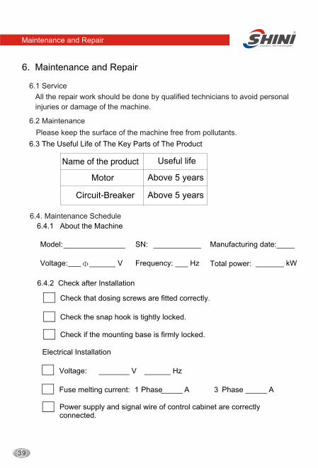
6. Maintenance and Repair
Maintenance and Repair
All the repair work should be done by qualified technicians to avoid personal
injuries or damage of the machine.
Please keep the surface of the machine free from pollutants.
6.2 Maintenance
Name of the product
6.1 Service
6.3 The Useful Life of The Key Parts of The Product
Motor
Circuit-Breaker
Above 5 years
Useful life
Above 5 years
Check that dosing screws are fitted correctly.
Check if the mounting base is firmly locked.
Power supply and signal wire of control cabinet are correctly connected.
6.4. Maintenance Schedule
Check the snap hook is tightly locked.
6.4.1 About the Machine
Model: SN: Manufacturing date:
Voltage:
V
Hz
kW
6.4.2 Check after Installation
Electrical Installation
Voltage:
V
Hz
Fuse melting current: 1 Phase A 3 Phase
A
Total power: Frequency:
6.4.3 Daily Checking
Maintenance and Repair
/ /
Check the main switch
Check fastening screws of mounting base
Check the main switch
Check fastening screws of mounting base
/ /
/ /
Check the main switch
Check fastening screws of mounting base
Check the main switch
Check fastening screws of mounting base
/ /
/ /
Check the main switch
Check fastening screws of mounting base
Check the main switch
Check fastening screws of mounting base
/ /
/ /
Check the main switch
Check fastening screws of mounting base
Check the main switch
Check fastening screws of mounting base
/ /
/ /
Check the main switch
Check fastening screws of mounting base
Check the main switch
Check fastening screws of mounting base
/ /
/ /
Check the main switch
Check fastening screws of mounting base
Check the main switch
Check fastening screws of mounting base
/ /
6.4.4 Weekly Checking
Maintenance and Repair
Check if there damaged electrical wires
Check snap hooks are loose or not
Check if the side holding plate is loose
or not
/ / / /
Check if there damaged electrical wires
Check snap hooks are loose or not
Check if the side holding plate is loose
or not
/ / / /
Check if there damaged electrical wires
Check snap hooks are loose or not
Check if the side holding plate is loose
or not
Check if there damaged electrical wires
Check snap hooks are loose or not
Check if the side holding plate is loose
or not
/ / / /
Check if there damaged electrical wires
Check snap hooks are loose or not
Check if the side holding plate is loose
or not
Check if there damaged electrical wires
Check snap hooks are loose or not
Check if the side holding plate is loose
or not
/ / / /
Check if there damaged electrical wires
Check snap hooks are loose or not
Check if the side holding plate is loose
or not
Check if there damaged electrical wires
Check snap hooks are loose or not
Check if the side holding plate is loose
or not
Maintenance and Repair
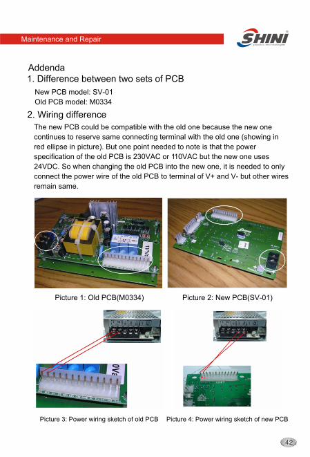
1. Difference between two sets of PCB
New PCB model: SV-01
Old PCB model: M0334
2. Wiring difference
The new PCB could be compatible with the old one because the new one
continues to reserve same connecting terminal with the old one (showing in
red ellipse in picture). But one point needed to note is that the power
specification of the old PCB is 230VAC or 110VAC but the new one uses
24VDC. So when changing the old PCB into the new one, it is needed to only
connect the power wire of the old PCB to terminal of V+ and V- but other wires
remain same.
Picture 1: Old PCB(M0334) Picture 2: New PCB(SV-01)
Picture 3: Power wiring sketch of old PCB Picture 4: Power wiring sketch of new PCB
Addenda
Maintenance and Repair
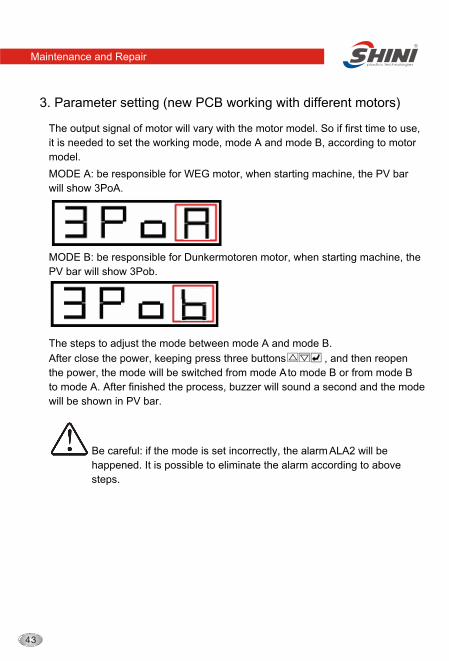
3. Parameter setting (new PCB working with different motors)
The output signal of motor will vary with the motor model. So if first time to use,
it is needed to set the working mode, mode A and mode B, according to motor
model.
MODE A: be responsible for WEG motor, when starting machine, the PV bar
will show 3PoA.
MODE B: be responsible for Dunkermotoren motor, when starting machine, the
PV bar will show 3Pob.
The steps to adjust the mode between mode A and mode B.
After close the power, keeping press three buttons , and then reopen
the power, the mode will be switched from mode A to mode B or from mode B
to mode A. After finished the process, buzzer will sound a second and the mode
will be shown in PV bar.
Be careful: if the mode is set incorrectly, the alarm ALA2 will be
happened. It is possible to eliminate the alarm according to above
steps.
Local Warranty Statement
1. Local warranty applies to the country of purchase only. Once the product is
transited out of the country of purchase, this warranty is invalidated.
2. The warranty is only applicable to the original purchaser and in the country
of purchase.
3. The warranty covers parts and labour only; and excludes freight and on-site
call-out charges.
4. Your SHINI product is guaranteed against manufacturing defects for a
period of twelve (12) months from the date of purchase locally unless stated
otherwise.
5. The warranty shall immediately cease and become void if the product is
found to have been modified or repaired by an unauthorized person.
6. The warranty is subjected to the following limitations and exclusions:
(a) Malfunctions or damages resulting from not complying with the
recommended manner as outlined in our operation manual in relation
with the application, installation, operation and maintenance.
(b) Defects from using wrong electrical supply, misuse or damage by
negligence and abuse.
(c) Malfunctions or damages resulting from natural disaster, fire, civil unrest
and / or accidents.
(d) Wear parts and accessories.
7. If your SHINI product is not the same place of purchase, you can still send
the product to your local SHINI's branch or distributor for servicing at your
full costs according to the individual country service policy.
8. If there is no SHINI's branch or distributor in your country, although
obviously there is no warranty covered by SHINI, you may direct contact
SHINI requesting for the supply of replacement parts at your full costs.
9. All the electricity installation, connection and maintenance should be
carried out by the specialists or contact , SHINI or its local agents.
Maintenance and Repair
(company stamp)
Product model:
Invoice Number:
Please send all queries and comments to:
Shini Plastics Technologies, Inc.
Corporate Strategic Center
Dalang, Dongguan, Guangdong, China
Tel: (0769) 8331 3588 Fax: (0769) 8331 3589
E-mail: [email protected]
www.shini.com
10. The warranty is deemed valid only if the followings are completely filled in:
Purchaser's name and address:
Your supplier's name and address:
Date of purchase:
Serial number:
HeadquartersShini Plastics Technologies, Inc.
Minhe St., Shulin City, Taipei, Taiwan
Tel +886 2 2680 9119
Fax +886 2 2680 9229
Website www.shini.comEmail: [email protected]
Factories
Taipei / Taiwan
Dongguan / China
Ningbo / China
Shanghai / China
Mumbai / India
Main Product
SHINI PLASTICS TECHNOLOGIES, INC.