Embed Size (px)
Citation preview
DURHAM UNIVERSITY
School of Engineering and
Computing Sciences
Level 2 Design
Feasibility Report on Rainwater Storage
and
Filtration in the Mekong Delta
Mission Statement: To design and provide a water collection, storage
and filtration system that is both affordable and effective for a
household in the Mekong Delta.
Authors: Kevin De Michelis, Charles Heard, Tom Pallister, Nick Sidwell,
Callum Stephen, Xaver Touschek
Supervisors: John Garside and Peter Waugh
Group 17.
1
Executive Summary
The objective of this project is to design and provide a water collection, storage and filtration system
that is both affordable and effective for a household in the Mekong Delta.
The Mekong Delta is an agricultural region in the south of Vietnam that experiences an annual rain
cycle consisting of a dry and wet season each of which lasts roughly 6 months. The average farmer
has a family of four and lives in a commune with a salary of less than $10 per day. This region is
difficult to access due to poor infrastructure and can mainly be reached by using the many rivers and
canals.
Currently, drinking water is collected from three sources: rainwater, borehole water, and surface
water. This water is typically stored in open cement or ceramic jars during the wet season. However,
this barely provides a family with enough water to last the dry season. Furthermore there is often a
build-up of impurities in their storage jars that leads to water contamination. There is also a lack of
adequate filtration which can cause severe water borne diseases and infections.
A domestic system that harvests rainwater was concluded as the most appropriate solution for the
Mekong Delta. A central communal water filtration plant had no way to distribute water due to a
lack of piping infrastructure and rainwater was deemed as the cleanest and most plentiful option.
The domestic approach means having to provide the knowledge and designs of the system to the
average farmer. Therefore the solution took into account locally sourced materials and local
businesses as well as providing clear and concise instructions for construction.
To make the process clear the solution was divided into three parts:
A more detailed and quantified user requirement specification table has been written up in the
main report for each section. However, these are the decisive factors that stood out:
Collection Storage Filtration
System User Requirement Specification
Collection Collection of 4m3 in 2 months.
Must allow water to be diverted away from tank to wash the roof.
Storage Removal of any initial contaminants.
Storage of 3600 litres.
Prevents sunlight access.
Costs less than $80.
Can be built by unskilled labourer.
Exit flow rate of 7.5 litres/min.
Filtration Filters > 90% of organic material.
No operational costs.
Flow rate > 3litres/person per day.
Costs less than $10.
2
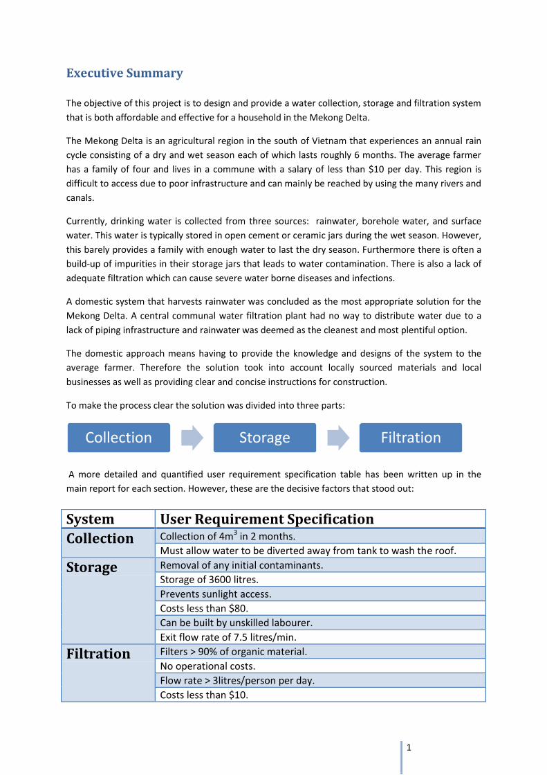
Collection:
Guttering System Final Design Key Physical aspects
Simple open gutters between roof and tank.
Removable section to allow water to be diverted away from tank.
Both gutters and supports made of bamboo.
Functionality Fully capable of filling the tank during the wet season (several times over)
Allows siphoning of water where required (eg to clean the roof) by the removable section.
Very easy for anyone to erect, maintain, and repair.
Total cost: $8.88
Storage:
Storage Tank Final Design Key Physical aspects
Built using ferrocement.
Bowl beneath tap to allow for water access.
Overflow pipe at top of tank.
Wash out pipe at bottom of tank.
Collection hole on sloped roof.
Inlet filter at entrance to tank
Functionality Stores 3,600 litres of water; enough to last a family of four through the six month dry season.
Does not allow exposure to sunlight.
It is robust enough to withstand flooding.
Construction time is under 2 weeks.
Instruction manual allows the tank to be built by an unskilled labourer.
Can safely withstand internal hydrostatic pressures at full capacity.
Water access has flow rate over 7.5 litres/minute
Tank can be easily maintained by an unskilled labourer
Initial filtration unit at the top avoids debris and insects from entering the tank.
Total cost: $65.38
3
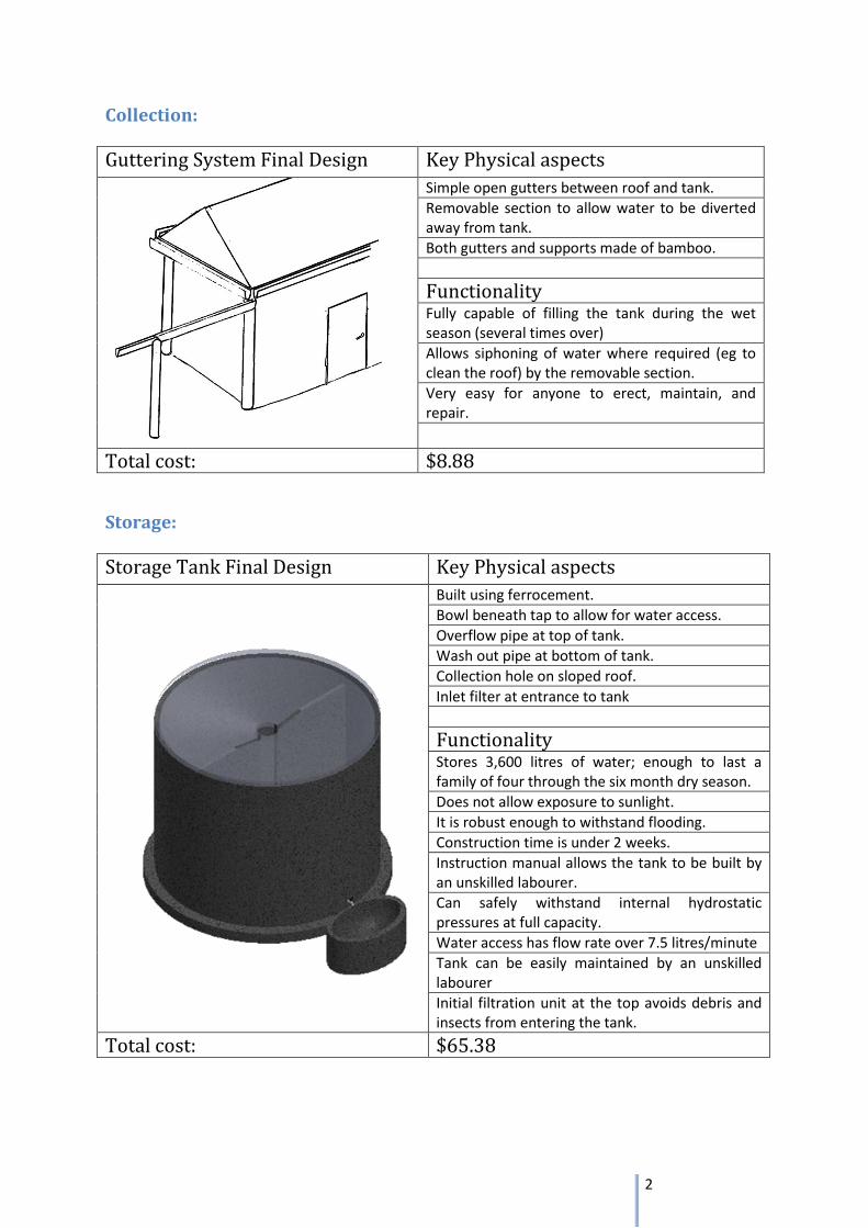
Filtration:
Filtration System Final Design Key Physical aspects
Clay pot filter running into plastic water butt
Ceramic pot is made from a 3:1 clay: rice husk mix
System is 660mm tall and 500mm wide
Plastic Butt is wider at the bottom for increased stability
Water is cleaned by physical straining and chemical action
Functionality Filters 3L of water per hour
Removes over 90% of bacteria
Reduces water turbidity to under 5%
Has zero power requirements
Only requires cleaning once a month
Very affordable at only $8.10
$8.10
Total cost:
The layout of each household in the Mekong Delta will inevitably differ from one another. However,
the design and implementation of each section within the project has allowed for greater
adaptability. The guttering system is fully adjustable to any roof dimensions whilst also providing
initial filtration. The storage tank can be positioned where ever the user desires it to be and has the
potential to be connected to the household via water piping. The filtration unit is easily portable and
unobtrusive within the home.
The collection, storage, and filtration designs have all successfully fulfilled their respective user
requirement specifications. Therefore this integrated system is the optimum rainwater storage and
filtration solution available to the people of the Mekong Delta.
4
Table of Contents
Executive Summary ................................................................................................................................. 1
Collection: ........................................................................................................................................... 2
Storage: ............................................................................................................................................... 2
Filtration: ............................................................................................................................................. 3
Team Assignment Overview ................................................................................................................... 9
1. Introduction ...................................................................................................................................... 10
1.1 Project Statement ....................................................................................................................... 10
1.2 Mekong Delta .............................................................................................................................. 10
1.3 Current Practice .......................................................................................................................... 10
1.4 Approach and Philosophy ........................................................................................................... 11
1.5 Project Management .................................................................................................................. 12
1.5.1 Planning ................................................................................................................................ 12
1.5.2 URS and feasibility report .................................................................................................... 12
1.5.3 Teamwork ............................................................................................................................ 12
Charlie Heard & Kevin De Michelis ....................................................................................................... 13
2. Collection .......................................................................................................................................... 14
2.1 Water sources ............................................................................................................................. 14
2.2 Concept developments ............................................................................................................... 15
2.3 Final design ................................................................................................................................. 16
2.3.1 Attaching to the roof ............................................................................................................ 16
2.3.2 Supporting the system ......................................................................................................... 17
2.3.3 The siphon ............................................................................................................................ 17
2.4 Sustainability ............................................................................................................................... 17
2.5 Manufacture ............................................................................................................................... 18
2.6 Final Costs ................................................................................................................................... 19
Thomas Pallister & Xaver Touschek ...................................................................................................... 20
3 Storage ............................................................................................................................................... 21
3.1 Current storage methods in the Mekong Delta .......................................................................... 21
3.1.1 Flow chart of processes ........................................................................................................... 21
3.2 Requirements for Storage system .............................................................................................. 22
3.3 Ferrocement as a material .......................................................................................................... 24
3.3.1 Material composition matrix ............................................................................................... 25
5
3.4 Availability of materials for construction .................................................................................... 27
3.4.1 Portland cement .................................................................................................................. 27
3.4.2 Fine grain sand ..................................................................................................................... 27
3.4.3 Potable water ....................................................................................................................... 27
3.4.4 Bamboo: ............................................................................................................................... 27
3.4.5 Wire mesh: ........................................................................................................................... 28
3.5 Ferrocement foundation theory ................................................................................................. 28
3.6 Water access ............................................................................................................................... 29
3.7 Concept design ........................................................................................................................ 31
3.8 Design development .............................................................................................................. 31
3.8.1 Problem Identification ......................................................................................................... 31
3.8.2 Problem solutions ................................................................................................................ 32
3.9 Final design ................................................................................................................................. 34
3.10 Structural Analysis: ................................................................................................................... 35
3.10.1 Analytical Conclusion: ........................................................................................................ 35
3.11 Inlet filter .................................................................................................................................. 35
3.12 Sustainable storage ................................................................................................................... 35
3.12.1 Life span of Tank ................................................................................................................ 35
3.12.2 Reducing ground Erosion ................................................................................................... 36
3.12.3 Flood Resistance ................................................................................................................ 36
3.12.4 Reduced Maintenance ....................................................................................................... 36
3.12.5 Locally Sourced Materials .................................................................................................. 36
3.13 Storage Manufacture ................................................................................................................ 36
3.14 Final Costing .............................................................................................................................. 37
3.15 Storage System Conclusion ....................................................................................................... 38
Callum Stephen & Nicholas Sidwell ...................................................................................................... 40
4 Filter Solutions ............................................................................................................................... 41
4.1 User Requirement Specifications ............................................................................................ 41
4.2 Potential Filtration Techniques ............................................................................................. 43
4.2.1 Slow Sand Filter .................................................................................................................... 43
4.2.2 Clay Pot ................................................................................................................................ 43
4.2.3 Why the Clay Pot? ................................................................................................................ 44
4.2.4 How the clay pot Works ....................................................................................................... 44
4.2.5 Silver Nitrate Solution .......................................................................................................... 45
4.3 Filtration System Development .................................................................................................. 46
6
4.4 Clay Pot Filter development ........................................................................................................ 47
4.4.3 Clay Pot Capacity .................................................................................................................. 47
4.4.4 Pot Lip .................................................................................................................................. 49
4.4.5 Shrinkage during Firing ........................................................................................................ 49
4.5 Chemical Treatment of the water ............................................................................................... 50
4.5.1 Water Treatment Chemicals ................................................................................................ 50
4.5.2 Silver Nitrate Solution .......................................................................................................... 50
4.6 Plastic Barrel Development ......................................................................................................... 51
4.6.1 Types of plastic ..................................................................................................................... 51
4.6.2 Initial Design ......................................................................................................................... 51
4.6.3 Changes in the design .......................................................................................................... 52
4.6.4 The Lid .................................................................................................................................. 52
4.7 Detailed filtration design ............................................................................................................ 52
4.7.1 Key Dimensions .................................................................................................................... 53
4.7.2 Clay Pot ................................................................................................................................ 53
4.8 Manufacturing Filtration System ................................................................................................ 54
4.8.1 Manufacture of Clay Pot Prototype in the UK ..................................................................... 54
4.8.2 Clay Mix ................................................................................................................................ 54
4.8.3 Clay Pot ................................................................................................................................ 54
4.8.4 Testing .................................................................................................................................. 54
4.8.5 Costs ..................................................................................................................................... 55
4.9 Manufacture in Vietnam ............................................................................................................. 56
4.9.1 Sourcing Clay Mix ................................................................................................................. 56
4.9.2 Clay Pot Moulding ................................................................................................................ 57
4.9.3 Drying and Firing .................................................................................................................. 57
4.9.4 Reusing discarded Pots ........................................................................................................ 58
4.9.4 Treating with Silver Nitrate .................................................................................................. 59
4.9.5 Making the solution ............................................................................................................. 59
4.9.6 Applying the Silver Solution ................................................................................................. 60
4.9.7 Cost of Silver Solution .......................................................................................................... 60
4.10 Water Butt Manufacture .......................................................................................................... 60
4.10.1 Plastic Barrel ...................................................................................................................... 60
4.10.2 Plastic Lid............................................................................................................................ 61
4.10.3 Plastic Tap .......................................................................................................................... 61
4.11 Manufacture Costing ................................................................................................................ 62
7
4.12 Filter Conclusion........................................................................................................................ 63
5 Discussion ...................................................................................................................................... 64
5.1 Adaptability of the integrated system ........................................................................................ 64
5.2 Improvements on current methods............................................................................................ 64
5.3 Total cost of integrated system and funding: ............................................................................. 65
5.4 Worst Case Scenarios and Contingency Plans ............................................................................ 66
5.4.1Flooding ................................................................................................................................ 66
5.4.2 Typhoons .............................................................................................................................. 66
6 Conclusion .......................................................................................................................................... 67
7 References ......................................................................................................................................... 68
Appendix A - Material Calculations ....................................................................................................... 69
Appendix B – Construction Guidelines ................................................................................................. 70
Appendix C – Stress Analysis of Tank .................................................................................................... 76
Appendix D – CAD Drawings ................................................................................................................. 83
Appendix E – Bamboo Handling Techniques ........................................................................................ 84
Instructions for cutting ..................................................................................................................... 84
Instructions for splitting .................................................................................................................... 85
How to Split Bamboo? ...................................................................................................................... 85
Important: Bamboo has 2 sides! .............................................................................................. 87
1. Straight Front: ......................................................................................................................... 87
2. Straight Cut Surface: ............................................................................................................. 88
Appendix F – Rainfall Data + Calculations ............................................................................................. 89
Appendix G – Example Meeting Minutes ............................................................................................. 90
Post holiday meeting (week 5) ......................................................................................................... 90
General points arising: .................................................................................................................. 90
Sectional updates: ......................................................................................................................... 90
Collection ...................................................................................................................................... 90
Storage .......................................................................................................................................... 90
Filtration ........................................................................................................................................ 90
Other general points: .................................................................................................................... 90
Weekly meeting – week 12 ............................................................................................................... 91
General points arising: .................................................................................................................. 91
Sectional updates: ......................................................................................................................... 91
Collection ...................................................................................................................................... 91
Storage .......................................................................................................................................... 91
8
Filtration ........................................................................................................................................ 91
Other general points: .................................................................................................................... 91
Figure 1 - Current guttering systems .................................................................................................... 14
Figure 2 - Manual (left) vs. automatic (right) siphon ............................................................................ 15
Figure 3 - Examples of automatic siphons ............................................................................................ 16
Figure 4 - Different methods to attach gutter to roof .......................................................................... 16
Figure 5 - Proposed method to attach gutter to roof ........................................................................... 17
Figure 6 - Supported guttering .............................................................................................................. 17
Figure 7 - Vietnamese People Splitting Bamboo .................................................................................. 18
Figure 8 - Guttering on the Roof ........................................................................................................... 18
Figure 9 - Shaping Bamboo Supports to Hold Guttering ...................................................................... 18
Figure 10 - Storage process flowchart .................................................................................................. 21
Figure 11 - Wire mesh ........................................................................................................................... 26
Figure 12 - Ferrocement foundation ..................................................................................................... 28
Figure 13 - Screw down tap .................................................................................................................. 29
Figure 14 - Ball valve hose tap .............................................................................................................. 29
Figure 15 - Loose head handle .............................................................................................................. 29
Figure 16 - Bent nose hose tap ............................................................................................................. 29
Figure 17 - Gate Valve tap ..................................................................................................................... 29
Figure 18- Design concept for ferrocement tank .................................................................................. 31
Figure 19 - Magnified view of tank displacements under load............................................................. 33
Figure 20- Final tank design .................................................................................................................. 34
Figure 21 - CAD drawing of inlet filter .................................................................................................. 35
Figure 22 - Filtration Process Flow Chart .............................................................................................. 44
Figure 23 – Pore Size ............................................................................................................................. 45
Figure 24 - Filtration Processes ............................................................................................................. 45
Figure 25 - Filter Composition ............................................................................................................... 46
Figure 26 - Exploded View Of Filter System .......................................................................................... 46
Figure 27 - Clay Pot Internal Angle........................................................................................................ 47
Figure 28 - Final Filter Process .............................................................................................................. 49
Figure 29 - Pot Lip ................................................................................................................................. 49
Figure 30 - Exploded View of Initial Design........................................................................................... 51
Figure 31 - Detailed Filter Design .......................................................................................................... 52
Figure 32 -Key Dimensions of detailed design ...................................................................................... 53
Figure 34 - Clay Pot Manufacturing Process ......................................................................................... 56
Figure 35 – Dry Bricks............................................................................................................................ 56
Figure 36 – Hammer Mill ...................................................................................................................... 57
Figure 37 - Press Mould ........................................................................................................................ 57
Figure 38 - Firing Process ...................................................................................................................... 58
Figure 39 - Recycling Process ................................................................................................................ 58
Figure 40 - Painting the Pot with Silver Solution .................................................................................. 60
Figure 41: Blow Moulding ..................................................................................................................... 60
Figure 42 - Joining the Handle to the Lid .............................................................................................. 61
Figure 43: Plastic Tap ............................................................................................................................ 61
9
Figure 44 - Final cost breakdown .......................................................................................................... 65
Table 1 - Water source decision matrix ................................................................................................ 14
Table 2 - Collection System Costing ...................................................................................................... 19
Table 3 - Currently available storage options ....................................................................................... 21
Table 4 - Storage URS ............................................................................................................................ 22
Table 5 - Decision matrix of different available storage methods ........................................................ 23
Table 6 - Sang grading scale .................................................................................................................. 25
Table 7 - Material availability ................................................................................................................ 28
Table 8 - Tap decision matrix ................................................................................................................ 30
Table 9 - Tank construction process ..................................................................................................... 37
Table 10 - Final tank costings ................................................................................................................ 38
Table 11 - Cost comparison ................................................................................................................... 39
Table 12 - Tank URS check .................................................................................................................... 39
Table 13 - Filtration URS ....................................................................................................................... 42
Table 14 - Filter Decision Matrix ........................................................................................................... 43
Table 15 - Pros and Cons of a Larger Clay Pot....................................................................................... 48
Table 16 – Types of Plastic .................................................................................................................... 51
Table 17 - Filter Costs ............................................................................................................................ 55
Table 18 - Manufacture Costs ............................................................................................................... 62
Table 19 - Completed Filtration URS ..................................................................................................... 63
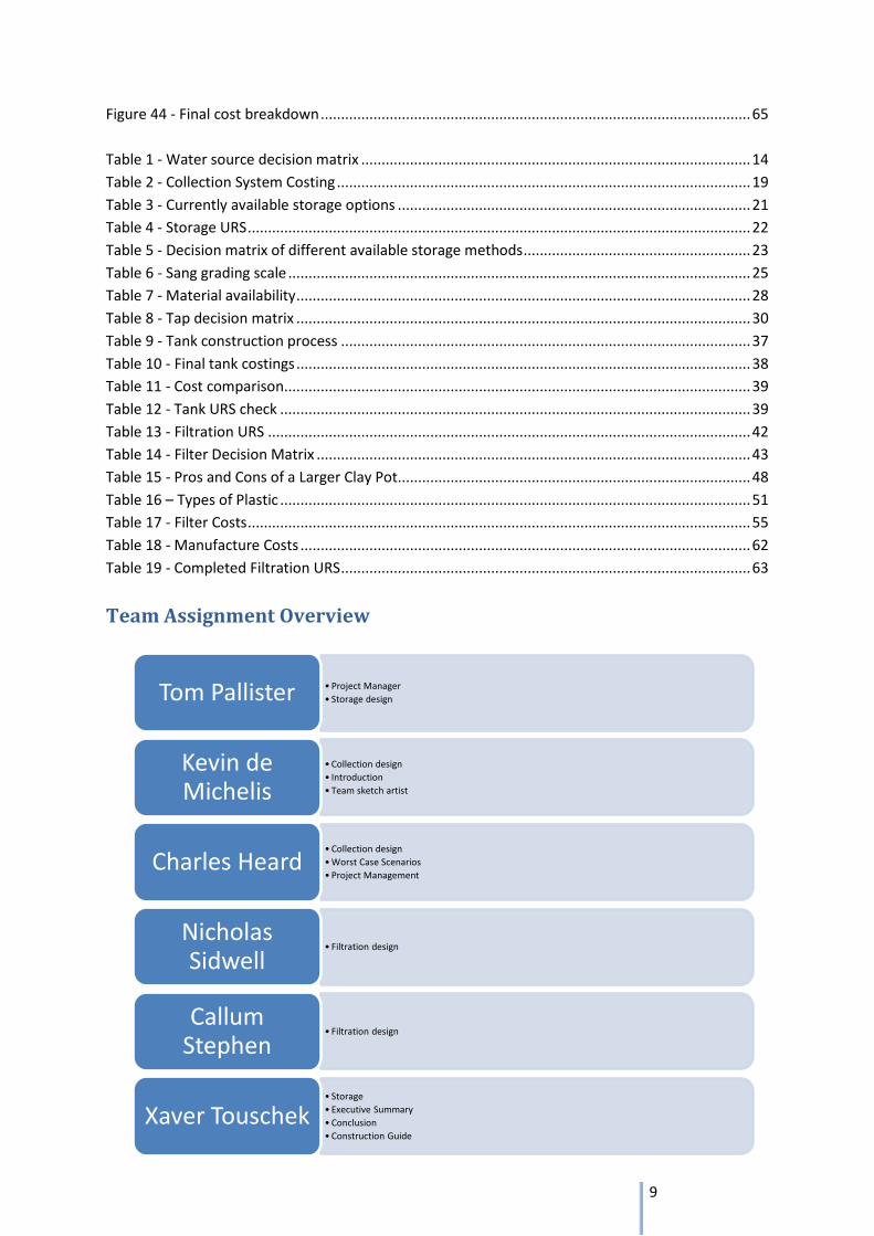
Team Assignment Overview
• Project Manager
• Storage design Tom Pallister
• Collection design
• Introduction
• Team sketch artist
Kevin de Michelis
• Collection design
• Worst Case Scenarios
• Project Management
Charles Heard
• Filtration design Nicholas Sidwell
• Filtration design Callum
Stephen
• Storage
• Executive Summary
• Conclusion
• Construction Guide
Xaver Touschek
10
1. Introduction
This report is a design solution for an Engineers Without Borders (EWB) Project in Vietnam.
1.1 Project Statement Access to clean drinking water is an important issue that needs to be addressed throughout the
Mekong Delta region. Drinking water is currently collected from three sources: rainwater, boreholes
and surface water. Rainwater is collected in open cement /ceramic jars during the wet season and
will typically provide a family with water for approximately five months of the year. Impurity build
up in the jars is a problem. The approach should take account of the nature of the terrain and
culture of the region make good use of renewable sources of energy and the nature of the materials
available and include mechanism of decanting the water to and from storage.
1.2 Mekong Delta The Mekong Delta is the region in the Anh Minh district in south-western Vietnam where the
Mekong River approaches and empties into the sea through a network of distributaries. Due to this
abundance of water and a six month monsoon season this is also an agricultural haven for the
Vietnamese rice farmers, and has numerous canals to aid the irrigation of the many rice fields. Thus
the area is referred to as flat flood plains and is, as implied, susceptible to floods during the wet
season. The wet season is a six month monsoon that South East Asia experiences in an annual rain
cycle, followed by a six month season of drought. The profusion of waterways means that the
principle mode of transport for both people and goods is boats and is otherwise very difficult to
access.
The average size for a rice farming family is 4.4 and they typically live in a house by the river or canal
to maximise the area of cultivatable land. The farmers are usually men as the work in the field is
considered ‘heavy’ work and for a man to do ‘light’ work, such as working in a factory, is culturally
unacceptable. However, though the women customarily do the ‘light’ work, they can work in the rice
fields too helping the men with several tasks, this is applicable to house building as well. Despite the
cultural gender separation in labour, men and women can work together to complete any necessary
task at hand; therefore any maintenance or construction can be performed by any member of the
family. The average wage of the rice farmers ranges from 6 - 9 USD/day.
1.3 Current Practice As mentioned in the project statement drinking water is primarily collected from three sources
during the wet season. This water stored provides the family with enough to last them most of the
dry season. However, this means the farmers must compensate, for the deficiency of water, using
boreholes throughout the dry season, yet only 85% of the families have access to them. There is also
a lack of proper maintenance in there storage system; impurities build-up, in the open aired
jars/tanks, and requires too much time and effort to upkeep them leading to water contamination.
Moreover, there is no current practice with which to filter the water afterwards causing possible
infections and severe diseases due to bacterial accumulation and viral contagions.
Having assessed the major problems with the system currently in place, a preliminary set of criteria
was stated. Firstly, an improved system of storage had to be implemented, the new method had to
provide the family with sufficient water and minimise the risk of water contamination. Secondly,
filtered water adhering to international SPHERE standards had to be introduced to the families’ daily
lives to reduce the number of infection and disease outbreaks. For these two measures to be
11
effective an efficient and clean water collection system also had to be added before the water
storage, to facilitate the rest of the operation. Finally, because of the very low salary of the people in
the region, the new system had to be financially viable and hence less expensive than the current
option.
1.4 Approach and Philosophy There were two lines to follow when thinking of a solution to the problem at hand. There was a
communal approach and a domestic approach. The communal methodology was based around a
centralised water filtration plant, while a domestic attitude would have a system in and around the
homes of the agriculturalists. The communes, however, are not organised into villages with typical
clusters of housing or buildings. Although they are more densely populated in the centre, the houses
are spread out along the banks of the canals and waterways that criss-cross the district. It was
evident that having water filtration plants spread across the Anh Minh district would have been
cheaper to the individuals but that there was currently a lack of piping infrastructure; the
construction and maintenance of such a network would have been near impossible with the regular
floods. On the other hand a domestic approach encouraged better accessibility and higher flexibility
to the clean water, thus a domestic design was chosen.
The prerequisites to the design solution lead to an obvious attitude with which the project would be
handled. The knowledge and designs provided had to be accessible, understandable and executed
by the average farmer, allowing him to self-build his own clean water system. To implement this, the
design uses locally sourced materials and local businesses as well as providing clear instructions for
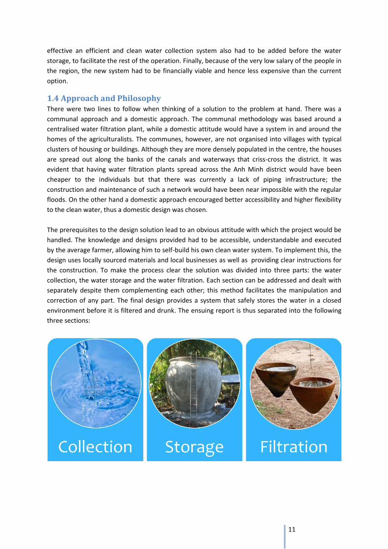
the construction. To make the process clear the solution was divided into three parts: the water
collection, the water storage and the water filtration. Each section can be addressed and dealt with
separately despite them complementing each other; this method facilitates the manipulation and
correction of any part. The final design provides a system that safely stores the water in a closed
environment before it is filtered and drunk. The ensuing report is thus separated into the following
three sections:
12
1.5 Project Management
1.5.1 Planning
The project was split into the three sections early on, and each section was assigned two team
members;
Collection – Charlie and Kevin
Storage – Tom and Xaver
Filtration – Callum and Nick
All the research and report writing for these sections were then to be done by their respective
members. Other areas were also assigned based on expected workload in the main sections;
Introduction – Kevin
Executive Summary – Xaver
Worst Case Scenarios – Charlie
Conclusion - Xaver
A Gantt chart was then made giving a schedule to the project (Appendix H).
Overall, the project followed the plan to a greater extent, some things took longer than expected –
the presentation for example put a complete stop to report writing for a week. The final order in
which the report was written and structured was changed adopt for this unexpected setback. An
initial finish date of three days before the deadline became just one; in which proof reading and final
editing took place.
1.5.2 URS and feasibility report
After the feasibility report, the group had a URS to work to and certain expectations of the project.
Unfortunately some of these quickly changed when detailed designs were drawn up. Costing, for
example, went up from $60 for the total system, to a total of just under $85. It was also discovered
that the guttering system should include a way to discard initial rainfalls; something not yet
discovered when the feasibility report was written.
The large initial URS was therefore edited slightly, removing some superfluous requirements, editing
others, and splitting it into sections for each part of the project.
1.5.3 Teamwork
The team met a minimum of twice a week throughout the project, these frequent meetings meant
that all members of the team were kept up to date with all other aspects of the project (Example of
minutes from some of these meetings can be found in Appendix G).
It also meant that most important decisions were made by the team as a whole rather than just the
team members assigned to that particular section. In a larger scale project this may have been
impractical but for this project it was a useful way to allow team members to support each other and
for no one team member to be overburdened at any point. The explanation of individual sections to
the whole team also worked as a way of reinforcing the understanding of one’s own and others’
sections as it highlighted things that were not fully understood or explained.
13
Water collection
Charlie Heard & Kevin De Michelis
14
Table 1 - Water source decision matrix
2. Collection There are two main concerns to be addressed within the water collection: collecting and delivering
the water to the tank and removing any initial impurities that could contaminate the water before
storage. This comes in two statements in the URS;
Collection of 4m3 in 2 months.
Must allow water to be diverted away from tank to wash the roof.
The 4m3 was calculated for an average family of 4 requiring 3.8 litres/person/day for both drinking
and cooking.
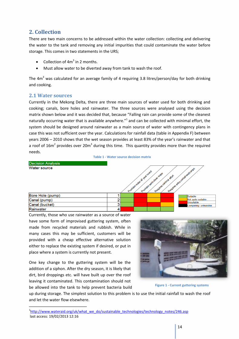
2.1 Water sources Currently in the Mekong Delta, there are three main sources of water used for both drinking and
cooking; canals, bore holes and rainwater. The three sources were analysed using the decision
matrix shown below and it was decided that, because “Falling rain can provide some of the cleanest
naturally occurring water that is available anywhere.”1 and can be collected with minimal effort, the
system should be designed around rainwater as a main source of water with contingency plans in
case this was not sufficient over the year. Calculations for rainfall data (table in Appendix F) between
years 2006 – 2010 shows that the wet season provides at least 83% of the year’s rainwater and that
a roof of 16m2 provides over 20m3 during this time. This quantity provides more than the required
needs.
Currently, those who use rainwater as a source of water
have some form of improvised guttering system, often
made from recycled materials and rubbish. While in
many cases this may be sufficient, customers will be
provided with a cheap effective alternative solution
either to replace the existing system if desired, or put in
place where a system is currently not present.
One key change to the guttering system will be the
addition of a siphon. After the dry season, it is likely that
dirt, bird droppings etc. will have built up over the roof
leaving it contaminated. This contamination should not
be allowed into the tank to help prevent bacteria build
up during storage. The simplest solution to this problem is to use the initial rainfall to wash the roof
and let the water flow elsewhere.
1http://www.wateraid.org/uk/what_we_do/sustainable_technologies/technology_notes/246.asp
last access: 19/02/2013 12:16
Figure 1 - Current guttering systems
15
2.2 Concept developments Getting the water from the roof to the tank will be a different challenge for every home; the roofing
will be different in almost every case and the tank may not necessarily be built very close to the
house. It is therefore difficult to come up with a single standard system. Instead, as the whole
system is to be self-built, rough instruction guidelines will be provided to the user on how to build a
system based on general guidelines and construction techniques.
The main construction material chosen was bamboo; it is the most readily available material, very
inexpensive and environmentally friendly. It will be used both as structural support and, when split,
the gutter itself.
As for the initial filter, this will be the same design for every customer. The first two rainfalls2 at the
start of the rainy season will be drained away to ensure none of the dirt accumulated on the roof
over the dry season pollutes the tank water. While the water is destined for a filter, it is beneficial to
store the water as cleanly as possible to prevent obstructing the tap or breeding bacteria. So to
implement this effectively a system had to be designed to allow for water to be diverted away from
the tank and then easily redirected.
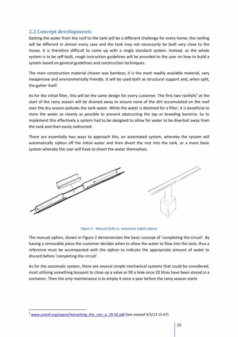
There are essentially two ways to approach this, an automated system, whereby the system will
automatically siphon off the initial water and then divert the rest into the tank, or a more basic
system whereby the user will have to divert the water themselves.
Figure 2 - Manual (left) vs. automatic (right) siphon
The manual siphon, shown in Figure 2 demonstrates the basic concept of ‘completing the circuit’. By
having a removable piece the customer decides when to allow the water to flow into the tank, thus a
reference must be accompanied with the siphon to indicate the appropriate amount of water to
discard before ‘completing the circuit’.
As for the automatic system, there are several simple mechanical systems that could be considered,
most utilising something buoyant to close up a valve or fill a hole once 20 litres have been stored in a
container. Then the only maintenance is to empty it once a year before the rainy season starts
2 www.unicef.org/eapro/Harvesting_the_rain_p_29-42.pdf (last viewed 4/3/13 15:47)
16
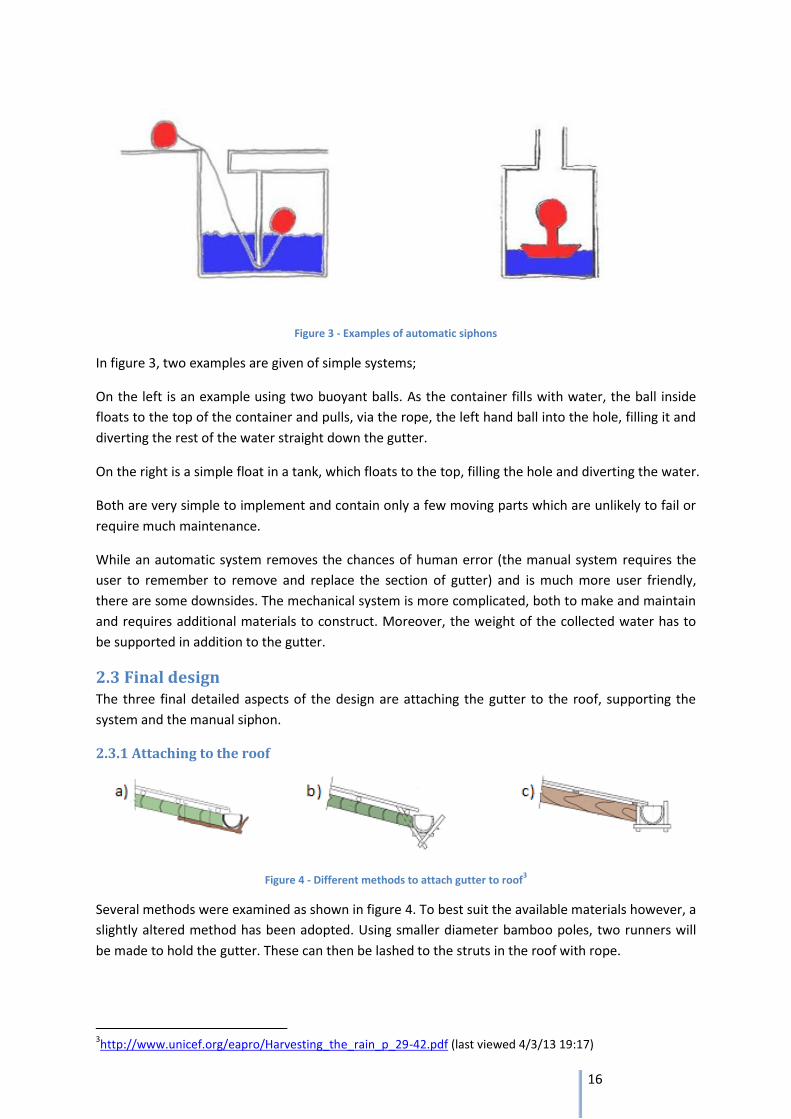
Figure 3 - Examples of automatic siphons
In figure 3, two examples are given of simple systems;
On the left is an example using two buoyant balls. As the container fills with water, the ball inside
floats to the top of the container and pulls, via the rope, the left hand ball into the hole, filling it and
diverting the rest of the water straight down the gutter.
On the right is a simple float in a tank, which floats to the top, filling the hole and diverting the water.
Both are very simple to implement and contain only a few moving parts which are unlikely to fail or
require much maintenance.
While an automatic system removes the chances of human error (the manual system requires the
user to remember to remove and replace the section of gutter) and is much more user friendly,
there are some downsides. The mechanical system is more complicated, both to make and maintain
and requires additional materials to construct. Moreover, the weight of the collected water has to
be supported in addition to the gutter.
2.3 Final design The three final detailed aspects of the design are attaching the gutter to the roof, supporting the
system and the manual siphon.
2.3.1 Attaching to the roof
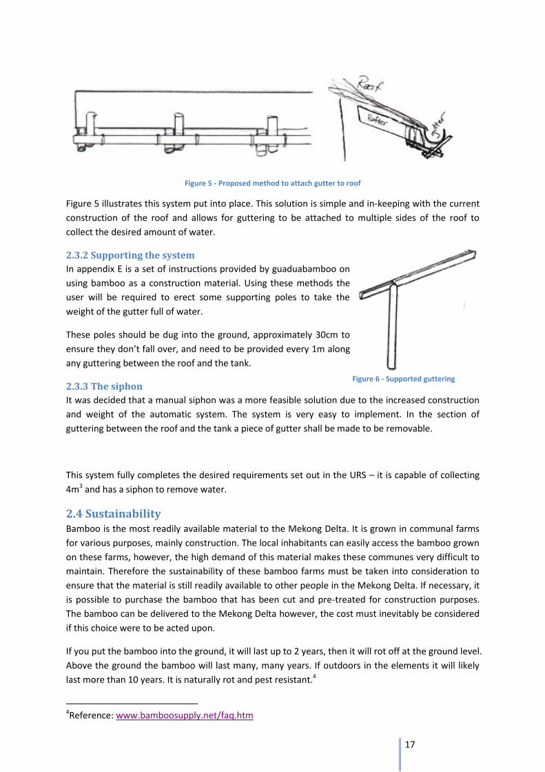
Figure 4 - Different methods to attach gutter to roof3
Several methods were examined as shown in figure 4. To best suit the available materials however, a
slightly altered method has been adopted. Using smaller diameter bamboo poles, two runners will
be made to hold the gutter. These can then be lashed to the struts in the roof with rope.
3http://www.unicef.org/eapro/Harvesting_the_rain_p_29-42.pdf (last viewed 4/3/13 19:17)
17
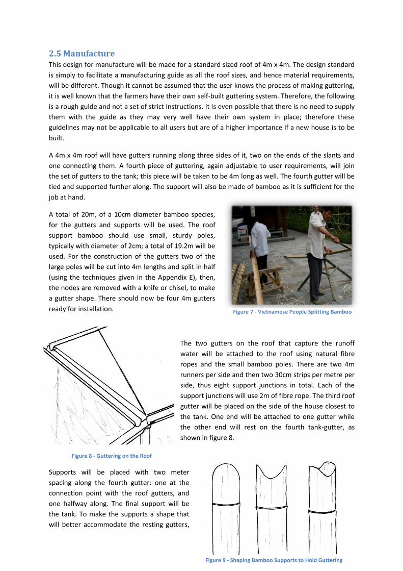
Figure 6 - Supported guttering
Figure 5 - Proposed method to attach gutter to roof
Figure 5 illustrates this system put into place. This solution is simple and in-keeping with the current
construction of the roof and allows for guttering to be attached to multiple sides of the roof to
collect the desired amount of water.
2.3.2 Supporting the system
In appendix E is a set of instructions provided by guaduabamboo on
using bamboo as a construction material. Using these methods the
user will be required to erect some supporting poles to take the
weight of the gutter full of water.
These poles should be dug into the ground, approximately 30cm to
ensure they don’t fall over, and need to be provided every 1m along
any guttering between the roof and the tank.
2.3.3 The siphon
It was decided that a manual siphon was a more feasible solution due to the increased construction
and weight of the automatic system. The system is very easy to implement. In the section of
guttering between the roof and the tank a piece of gutter shall be made to be removable.
This system fully completes the desired requirements set out in the URS – it is capable of collecting
4m3 and has a siphon to remove water.
2.4 Sustainability Bamboo is the most readily available material to the Mekong Delta. It is grown in communal farms
for various purposes, mainly construction. The local inhabitants can easily access the bamboo grown
on these farms, however, the high demand of this material makes these communes very difficult to
maintain. Therefore the sustainability of these bamboo farms must be taken into consideration to
ensure that the material is still readily available to other people in the Mekong Delta. If necessary, it
is possible to purchase the bamboo that has been cut and pre-treated for construction purposes.
The bamboo can be delivered to the Mekong Delta however, the cost must inevitably be considered
if this choice were to be acted upon.
If you put the bamboo into the ground, it will last up to 2 years, then it will rot off at the ground level.
Above the ground the bamboo will last many, many years. If outdoors in the elements it will likely
last more than 10 years. It is naturally rot and pest resistant.4
4Reference: www.bamboosupply.net/faq.htm
18
Figure 7 - Vietnamese People Splitting Bamboo
Figure 8 - Guttering on the Roof
2.5 Manufacture This design for manufacture will be made for a standard sized roof of 4m x 4m. The design standard
is simply to facilitate a manufacturing guide as all the roof sizes, and hence material requirements,
will be different. Though it cannot be assumed that the user knows the process of making guttering,
it is well known that the farmers have their own self-built guttering system. Therefore, the following
is a rough guide and not a set of strict instructions. It is even possible that there is no need to supply
them with the guide as they may very well have their own system in place; therefore these
guidelines may not be applicable to all users but are of a higher importance if a new house is to be
built.
A 4m x 4m roof will have gutters running along three sides of it, two on the ends of the slants and
one connecting them. A fourth piece of guttering, again adjustable to user requirements, will join
the set of gutters to the tank; this piece will be taken to be 4m long as well. The fourth gutter will be
tied and supported further along. The support will also be made of bamboo as it is sufficient for the
job at hand.
A total of 20m, of a 10cm diameter bamboo species,
for the gutters and supports will be used. The roof
support bamboo should use small, sturdy poles,
typically with diameter of 2cm; a total of 19.2m will be
used. For the construction of the gutters two of the
large poles will be cut into 4m lengths and split in half
(using the techniques given in the Appendix E), then,
the nodes are removed with a knife or chisel, to make
a gutter shape. There should now be four 4m gutters
ready for installation.
The two gutters on the roof that capture the runoff
water will be attached to the roof using natural fibre
ropes and the small bamboo poles. There are two 4m
runners per side and then two 30cm strips per metre per
side, thus eight support junctions in total. Each of the
support junctions will use 2m of fibre rope. The third roof
gutter will be placed on the side of the house closest to
the tank. One end will be attached to one gutter while
the other end will rest on the fourth tank-gutter, as
shown in figure 8.
Supports will be placed with two meter
spacing along the fourth gutter: one at the
connection point with the roof gutters, and
one halfway along. The final support will be
the tank. To make the supports a shape that
will better accommodate the resting gutters,
Figure 9 - Shaping Bamboo Supports to Hold Guttering
19
the end must be cut in a ‘U’ shape as shown in figure 9. The supports should be buried at least 30cm
into the ground to ensure adequate stability. Four metres of bamboo has been estimated for the
supports though the height of the bamboo poles needed depends wholly on the height of the user’s
house.
The fourth gutter can now be cut in half; leaving one end permanently fixed at the roof connection
and the other half now a removable piece as discussed in the concept development.
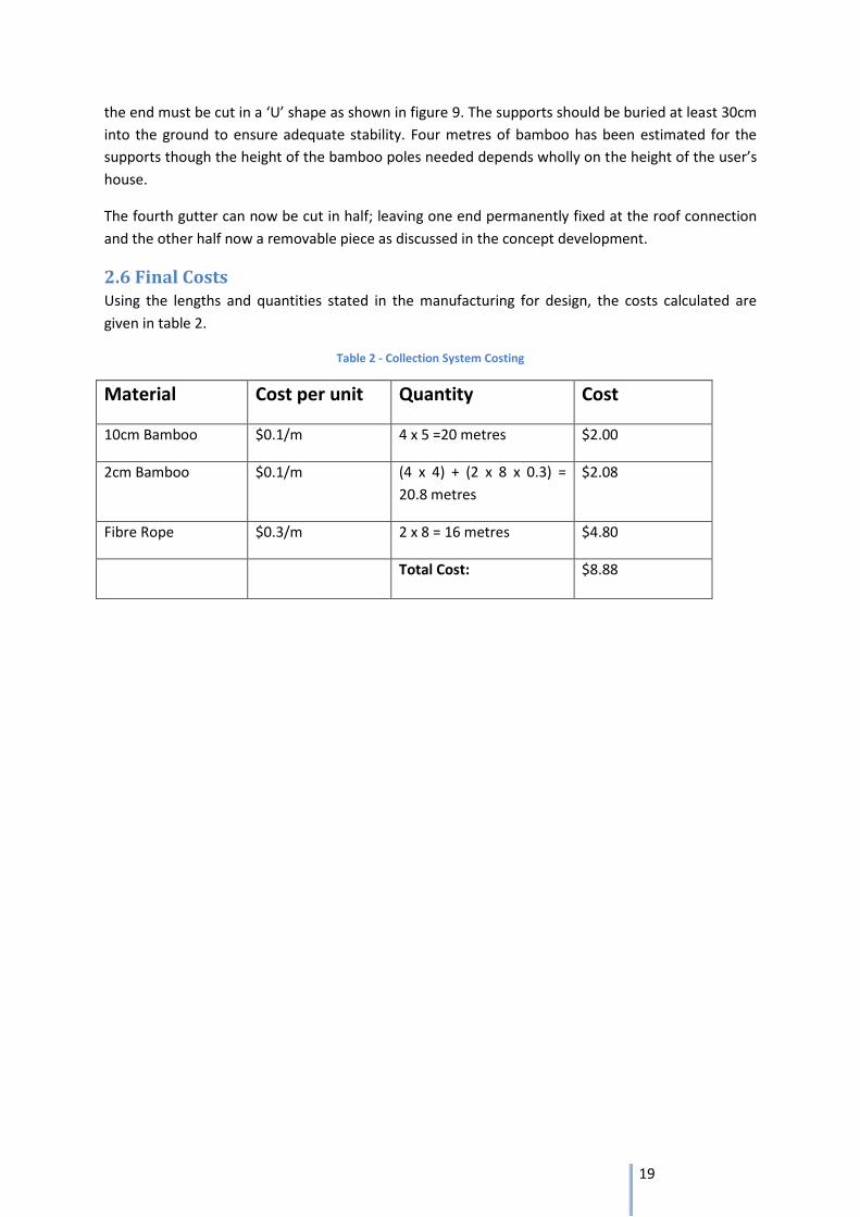
2.6 Final Costs Using the lengths and quantities stated in the manufacturing for design, the costs calculated are
given in table 2.
Table 2 - Collection System Costing
Material Cost per unit Quantity Cost
10cm Bamboo $0.1/m 4 x 5 =20 metres $2.00
2cm Bamboo $0.1/m (4 x 4) + (2 x 8 x 0.3) =
20.8 metres
$2.08
Fibre Rope $0.3/m 2 x 8 = 16 metres $4.80
Total Cost: $8.88
20
Water Storage
Thomas Pallister & Xaver Touschek
21
3 Storage
3.1 Current storage methods in the Mekong Delta
Rainwater harvesting is common throughout the Mekong Delta region. The current storage method
adopted by many households is to have large ceramic, open-top jars placed adjacent to the
household. This is normally accompanied by an improvised guttering system that channels rainwater
from the roof to the jar itself. However, there are many disadvantages with this method. Firstly the
storage capacity of these jars is limited to a maximum of 1000 litres which is an insufficient volume
to adequately provide for a family of 4 during the 6 month dry season. Secondly, the fact that these
jars are open-top means that there are serious implications for the quality of water stored inside.
When stored water is exposed to sunlight and air, bacteria can grow as well as other water borne
viruses such as e-coli. This exposure also allows the water to be contaminated with impurities such
as debris or insects. Lastly, these jars are prone to breaking and frequently need to be replaced
which places a financial strain on the families.
There are other storage options available in the Mekong Delta such as plastic water tanks.
However, these options are frequently more expensive than the ceramic jars. Table 3 shows the
projected cost of installing a sufficient number of water tanks that will provide for a family of 4
during a 6 month dry season:
Table 3 - Currently available storage options
Storage option Capacity Individual Cost Total Cost
Ceramic Jars 1000 litres $20 $80
Plastic Water Tanks 1000 litres 500 litres
$80 $50
$320 $400
As illustrated, it is far less expensive to install a system of ceramic jars rather than plastic tanks.
However, installing ceramic jars incurs all the disadvantages mentioned previously.
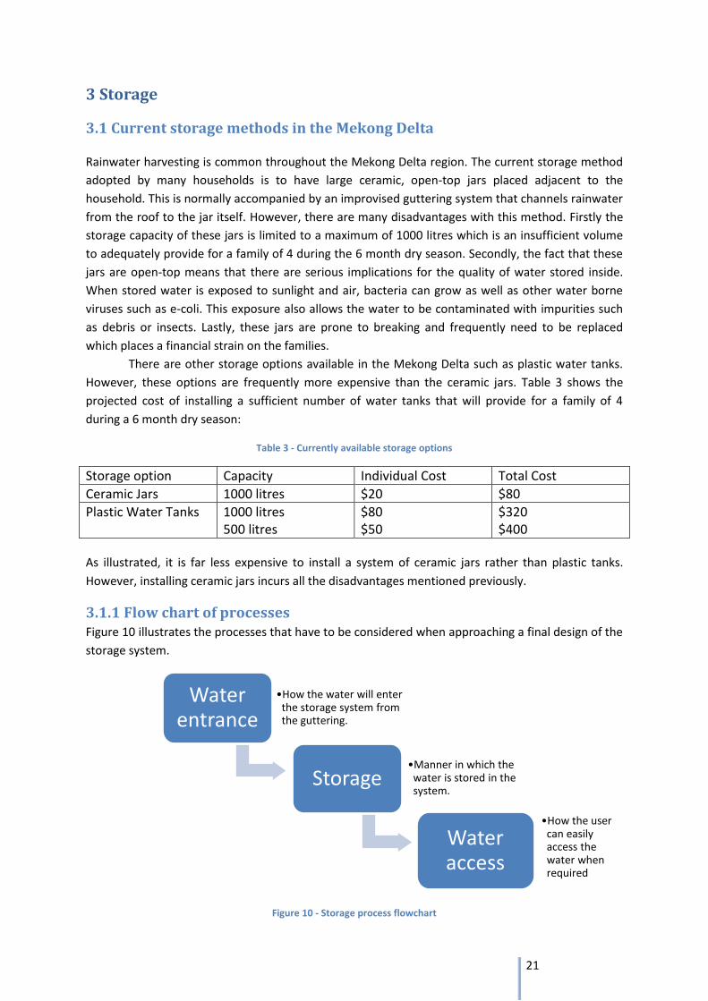
3.1.1 Flow chart of processes Figure 10 illustrates the processes that have to be considered when approaching a final design of the
storage system.
Figure 10 - Storage process flowchart
Water entrance
•How the water will enter the storage system from the guttering.
Storage •Manner in which the
water is stored in the system.
Water access
•How the user can easily access the water when required
22
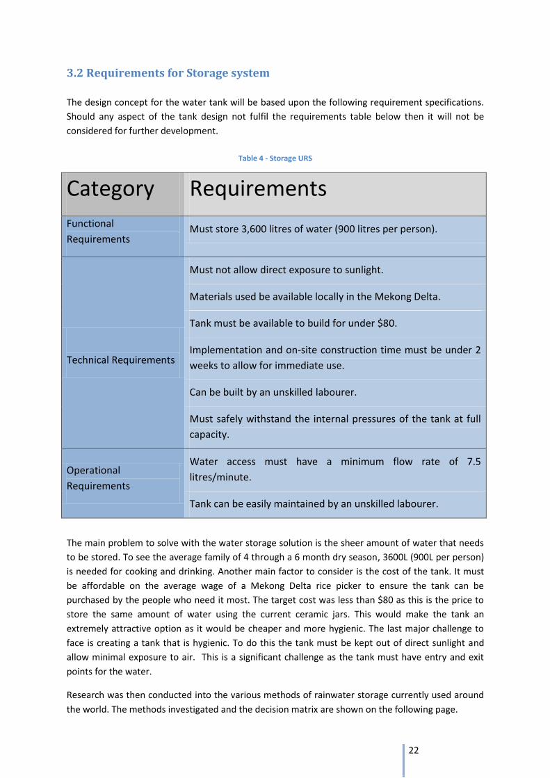
3.2 Requirements for Storage system
The design concept for the water tank will be based upon the following requirement specifications.
Should any aspect of the tank design not fulfil the requirements table below then it will not be
considered for further development.
Table 4 - Storage URS
Category Requirements
Functional
Requirements Must store 3,600 litres of water (900 litres per person).
Technical Requirements
Must not allow direct exposure to sunlight.
Materials used be available locally in the Mekong Delta.
Tank must be available to build for under $80.
Implementation and on-site construction time must be under 2
weeks to allow for immediate use.
Can be built by an unskilled labourer.
Must safely withstand the internal pressures of the tank at full
capacity.
Operational
Requirements
Water access must have a minimum flow rate of 7.5
litres/minute.
Tank can be easily maintained by an unskilled labourer.
The main problem to solve with the water storage solution is the sheer amount of water that needs
to be stored. To see the average family of 4 through a 6 month dry season, 3600L (900L per person)
is needed for cooking and drinking. Another main factor to consider is the cost of the tank. It must
be affordable on the average wage of a Mekong Delta rice picker to ensure the tank can be
purchased by the people who need it most. The target cost was less than $80 as this is the price to
store the same amount of water using the current ceramic jars. This would make the tank an
extremely attractive option as it would be cheaper and more hygienic. The last major challenge to
face is creating a tank that is hygienic. To do this the tank must be kept out of direct sunlight and
allow minimal exposure to air. This is a significant challenge as the tank must have entry and exit
points for the water.
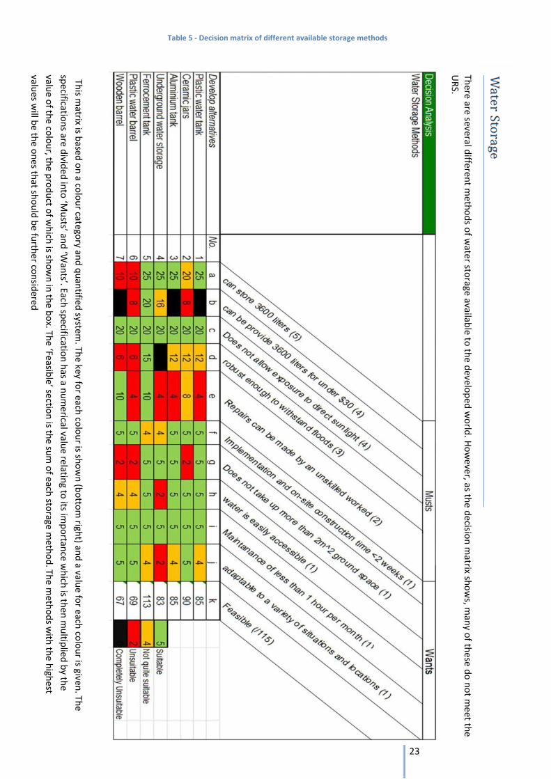
Research was then conducted into the various methods of rainwater storage currently used around
the world. The methods investigated and the decision matrix are shown on the following page.
23
This m
atrix is based
on
a colo
ur cate
gory an
d q
uan
tified system
. The key fo
r each co
lou
r is sho
wn
(bo
ttom
right) an
d a valu
e for each
colo
ur is given
. The
specificatio
ns are d
ivided
into
‘Mu
sts’ and
‘Wan
ts’. Each sp
ecification
has a n
um
erical value relatin
g to its im
po
rtance w
hich
is then
mu
ltiplied
by th
e
value o
f the co
lou
r, the p
rod
uct o
f wh
ich is sh
ow
n in
the b
ox. Th
e ‘Feasible’ sectio
n is th
e sum
of e
ach sto
rage meth
od
. The m
etho
ds w
ith th
e high
est
values w
ill be th
e on
es that sh
ou
ld b
e furth
er con
sidered
There are several d
ifferent m
etho
ds o
f wate
r storage availab
le to th
e develo
ped
wo
rld. H
ow
ever, as the d
ecision
matrix sh
ow
s, man
y of th
ese do
no
t mee
t the
UR
S.
Table 5 - Decision matrix of different available storage methods
24
3.3 Ferrocement as a material
Ferrocement is a form of reinforced concrete that differs from the conventional reinforced or pre-
stressed concrete that is commonly used in industrial building. The principle difference between the
two is the manner in which the reinforcing elements are arranged and dispersed within the mortar.
The reinforcement for ferrocement normally consists of closely spaced layers of wire mesh that are
supported by rods or poles; cement mortar is then applied over the mesh. The resultant composite
material formed has different behavioural characteristics in terms of strength, deformation and
potential applications.
Although the name implies a ferrous reinforcement, the same characteristics can still be achieved
using materials other than steel meshes or rod. This ensures that the use of ferrocement is not
subjected purely to countries or communities that have quick and inexpensive access to ferrous
materials. Indeed, replacement materials for steel meshes that have been used, either in practice or
purely for experimentation, have included organic woven fabrics such as polypropylene and organic
natural fabrics made with jute, burlap, or bamboo fibres.
Ferrocement also has a very high tensile strength-to-weight ratio and a superior cracking behaviour
in comparison to conventional reinforced concrete. This means that structures made out of
ferrocement can be made relatively light and water tight. Furthermore the malleability of the
reinforcement meshes allows one to easily alter the dimensions of a structure. These characteristics
make ferrocement an attractive material for water tight structures such as water tanks and barges.
The basic construction process for any ferrocement structure is as follows:
1. Initial foundation that is appropriate to the structure being built.
2. Construction of steel rods (or other material) to form a skeletal framing.
3. Attaching mesh to skeletal framing.
4. Plastering of mortar.
5. Curing.
The simplistic construction processes means that only low level technical skills are required and the
fabrication of small scale projects can be performed by an unskilled labourer.
The following conclusions are based on a report on ferrocement water tanks, conducted by the
Science Museum of Virginia:5
1. Ferrocement is an economically feasible material for the construction of water storage tanks.
2. Flexibility of shape, freedom from corrosion, possibility of hot storage, relative lack of
maintenance, and ductile mode of failure are important advantages of ferrocement over
other materials commonly used for low to medium pressure (up to 345kPa) storage of fluids.
3. Ferrocement tanks require less energy to produce than steel tanks.
Therefore ferrocement, as a material, appears to have the largest potential to fulfil the user
requirements specifications.
5http://www.bpesol.com/bachphuong/media/images/book/549r_97.pdf (last accessed 5/3/2013 15:31)
25
3.3.1 Material composition matrix
Ferrocement consists of Portland mortar, reinforcement, admixtures and coatings. To achieve the
appropriate tensile and compressive strength characteristics of the tank it is necessary to perfect the
proportions of the mortar components. This is dependent upon the nature of the sand, chemical
composition of the cement, the water-cement ratio and the curing of the finished tank.
3.3.1.1 Matrix mix proportions
The mix proportions’ ranges for ferrocement mortar are as follows6:
• Sand - Cement ration by weight: 1.4 - 2.5 : 1
• Water - Cement ratio by weight: 0.3 - 0.5 : 1
These ranges have yielded satisfactory results and should be adhered to when constructing the tank.
The quality of sand factors greatly towards a high calibre mortar. Well graded, rounded, natural sand
having a maximum top size of about one-third of the smallest opening in the reinforcing system to
ensure proper penetration. 7 The water used should also be of relatively high quality and free from
contaminated organic matter. The presence of these impurities will weaken the mortar matrix.
Curing the ferrocement once construction has finished is important for attaining the maximum
strength characteristics of the mortar and the prevention of cracking. Curing can be performed by
either wetting the surfaces regularly or covering the structure in polythene sheeting to contain the
moisture. This process must be maintained for at least two weeks before the structure is suitable for
use.
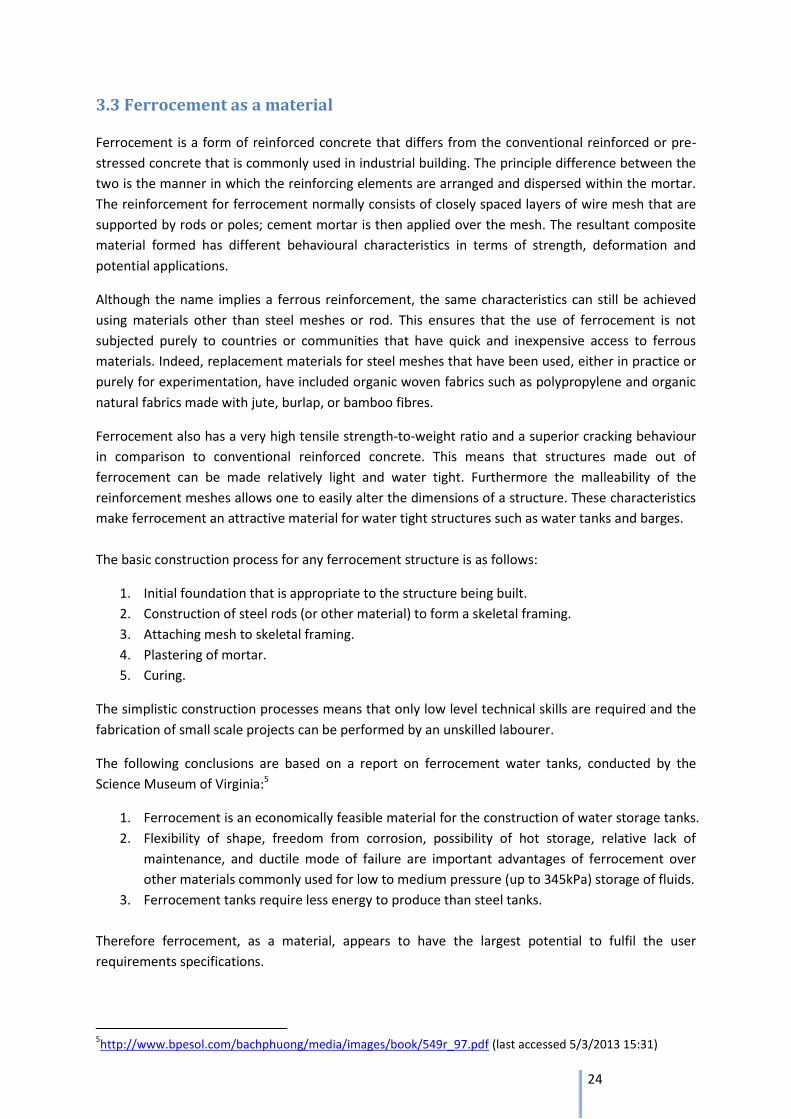
3.3.1.2 Sand
The desirable sand grading for ferrocement mortar is as follows:8
Table 6 - Sang grading scale
Sieve Per cent Passing 3/8 in. (9.5 mm) 100
No. 4 (4.75mm) 95 – 100
No. 8 (2.36mm) 80 – 100
No. 14 (1.18mm) 50 – 85
No. 30 (600μm) 25 – 60
No. 100 (150μm) 2 – 10
3.3.2 Reinforcement
The reinforcement of ferrocement is commonly in the form of intertwined wire that creates a mesh.
Traditionally the mesh layers are attached by hand to a framework of poles and the mortar is applied
to the meshed structure and plastered on either side. The wire mesh acts to distribute the loads
experienced within the tank through the mortar and across the structural frame. However, this
method is liable to create voids on the peripheries of the rods. In fact, U.S. Navy research on high-
performance ferrocement hulls concluded that steel rods were ineffective at reinforcing a structure
6 ACI Committee 549, ‘State-of-the-art Report on Ferrocement’, January 24 1997, p 7.
7 Ibid p. 7. 8 United Nations High Commissioner for Refugees, ‘Large Ferro-Cement Water Tank, Design Parameters and
Construction Details’, July 2006, p. 16.
26
and in some cases are detrimental to the structural stability of the final product9. This is because the
poles are not loaded to take advantage of their strength; the spacing they create when the mortar is
applied allows for regions of unreinforced mortar that contributes to weight but not to strength.
They actually act as stress concentrators. The need for steel rods was eliminated by applying the
mortar to the mesh which is supported by frames made of wood strips, ply wood and even bamboo.
Therefore the requirements for the reinforcement of the ferrocement tank can easily be
accomplished using bamboo for the structural framework and chicken wire as the mesh. Not only
can the same strength characteristics be achieved using these materials but it also eliminates the
need for steel to be used for the framework which saves money on material expenses.
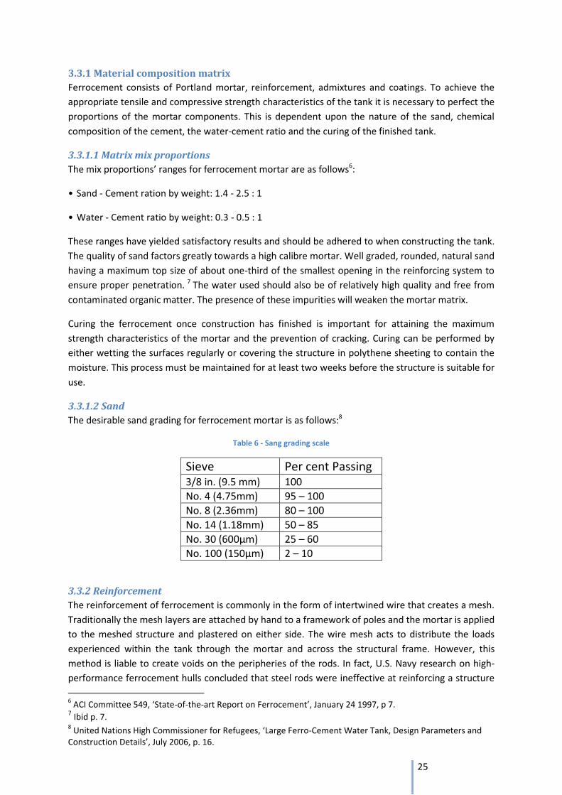
3.3.2.1 Wire Mesh
According to the United Nations High Commission for Refugees,
the ideal type of wire mesh for use in ferrocement structures
should have the following properties.10
1. Must be easy to handle and flexible enough to bend.
2. Galvanized wire mesh is preferable as it is less likely to rust or
corrode.
3. 0.5 - 1.0 mm diameter with 10 - 25 mm mesh opening.
4. Free from grease and anything that might reduce bond.
3.3.2.2 Bamboo
Despite the convenience of using bamboo for the framework, it still needs to well treated before
construction. Untreated bamboo poles have the distinct risk of swelling when in contact with
ferrocement that is settling. Therefore preparation must be taken with the sizing, seasoning and
waterproofing.
Split bamboo is generally more desirable than whole culms as reinforcement. Hollowed
bamboo creates stress concentration points within the ferrocement which can affect the structural
stability of the tank. By splitting the culm in half these stress concentration points are avoided.
Splitting the bamboo can be done by separating the base with a sharp knife then, using a dull blade,
continue this separation throughout the culm.
When possible, the bamboo should be cut and allowed to dry and season at least 3 – 4
weeks prior to construction 11 . Seasoning the bamboo allows it to increase its strength
characteristics. During this process the culms should be supported at regular intervals to avoid
warping.
When seasoned bamboo, either split or whole, is used as reinforcement, it should receive a
waterproof coating to reduce swelling when in contact with concrete. Without any coating the
bamboo will swell before the ferrocement has settled and developed sufficient strength to prevent
cracking. However, only a thin layer should be applied; thick layers tend to lubricate the surface of
the bamboo and consequently the bonds with the ferrocement mortar will weaken. The type of
coating will inevitably depend on the materials available in the Mekong Delta.
9 ACI Committee 549, ‘State-of-the-art Report on Ferrocement’, January 24 1997, p 7.
10 United Nations High Commissioner for Refugees, ‘Large Ferro-Cement Water Tank, Design Parameters and
Construction Details’, July 2006, p. 16. 11
Francis E. Brink and Paul J. Rush ‘BAMBOO REINFORCED CONCRETE CONSTRUCTION’, Port Hueneme, California, February 1966, p.4.
10 -25 mm
Figure 11 - Wire mesh
27
3.4 Availability of materials for construction
When building any structure using ferrocement it is highly important that the ingredients are readily
and locally available. In the research it was ensured that there were two reliable sources of
materials; an ideal first option and a contingency option if the 1st proves to be unfeasible. The
principle materials required for the construction of a ferrocement structure are listed as follows:
• Portland cement.
• Fine-grain sand.
• Potable and organic matter-free water.
• Wire mesh.
• Bamboo poles for frame work.
3.4.1 Portland cement The most readily available cement to the Mekong Delta is Portland cement PCB40 which has various
advantageous characteristics. Its low alkali content helps improve the concrete’s durability and
prevents steel inside the concrete from being corroded by alkali-aggregate reactions, PCB40 meets
the American standards for cement12. This cement is manufactured by a Vietnamese based company
called Thang Long Cement who supplies their products to the Mekong Delta Region. However, if for
some unexplained reason this option is unfeasible then there is a cement factory located in Rach Gia
which is in the Mekong Delta region13. Portland cement can very easily be sourced from this factory.
3.4.2 Fine grain sand
According to the research this is readily available to the communes of the Mekong Delta. In fact the
sand on the banks of the Mekong Delta is used as a source of mortar sand for the whole of Vietnam.
Its quality and abundance fortunately means that there is a plentiful supply of mortar sand available
to people in the Mekong Delta.
3.4.3 Potable water
The water quality of borehole water and harvested rainwater is sufficient enough to yield a good
quality mortar but not water from the river. Borehole wells are accessible to 85%14 of households in
the Mekong Delta whilst all other households already have in place methods of storing large
quantities of rainwater. Rainwater is the preferable option for mixing the mortar as it is of a better
quality than borehole water. However, stored rainwater is obviously a precious commodity so any
opportunity to conserve it must be acted upon. If the use of rainwater proves to be far too
impractical and detrimental to a household then borehole water is of a satisfactory quality for
mortar mixing.
3.4.4 Bamboo: As stated in section 2.4, bamboo is a highly adequate material and ideal for the construction of the
tank.
12
http://thanglongcement.com.vn/en/news/company-news/thang-long-cement-jsc-is-listed-in-the-prestigious-vnr500-ranking-board. Last accessed 03/03/2013. 13
http://www.ewb.org.au/discussions/1273/11437’ last accessed 05/03/2013. 14
http://www.ewb.org.au/explore/initiatives/ewbchallenge/hfhewbchallenge/hfhwash last accessed 01/03/2013
28
Rebar frame
Figure 12 - Ferrocement foundation
3.4.5 Wire mesh:
Wire mesh is a very common material available to everyone in the Mekong Delta at a set price. Sold
at a set width of 1.6 metres it is an essential material for farming and fishing techniques of all
families.15
The table below summarises the ideal and contingency material availability in the Mekong Delta.
Table 7 - Material availability
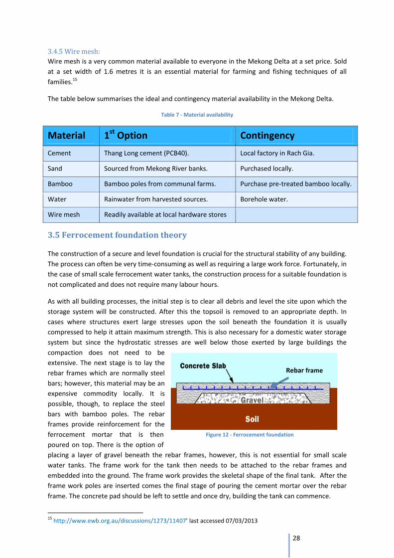
3.5 Ferrocement foundation theory
The construction of a secure and level foundation is crucial for the structural stability of any building.
The process can often be very time-consuming as well as requiring a large work force. Fortunately, in
the case of small scale ferrocement water tanks, the construction process for a suitable foundation is
not complicated and does not require many labour hours.
As with all building processes, the initial step is to clear all debris and level the site upon which the
storage system will be constructed. After this the topsoil is removed to an appropriate depth. In
cases where structures exert large stresses upon the soil beneath the foundation it is usually
compressed to help it attain maximum strength. This is also necessary for a domestic water storage
system but since the hydrostatic stresses are well below those exerted by large buildings the
compaction does not need to be
extensive. The next stage is to lay the
rebar frames which are normally steel
bars; however, this material may be an
expensive commodity locally. It is
possible, though, to replace the steel
bars with bamboo poles. The rebar
frames provide reinforcement for the
ferrocement mortar that is then
poured on top. There is the option of
placing a layer of gravel beneath the rebar frames, however, this is not essential for small scale
water tanks. The frame work for the tank then needs to be attached to the rebar frames and
embedded into the ground. The frame work provides the skeletal shape of the final tank. After the
frame work poles are inserted comes the final stage of pouring the cement mortar over the rebar
frame. The concrete pad should be left to settle and once dry, building the tank can commence.
15
http://www.ewb.org.au/discussions/1273/11407’ last accessed 07/03/2013
Material 1st Option Contingency
Cement Thang Long cement (PCB40). Local factory in Rach Gia.
Sand Sourced from Mekong River banks. Purchased locally.
Bamboo Bamboo poles from communal farms. Purchase pre-treated bamboo locally.
Water Rainwater from harvested sources. Borehole water.
Wire mesh Readily available at local hardware stores
29
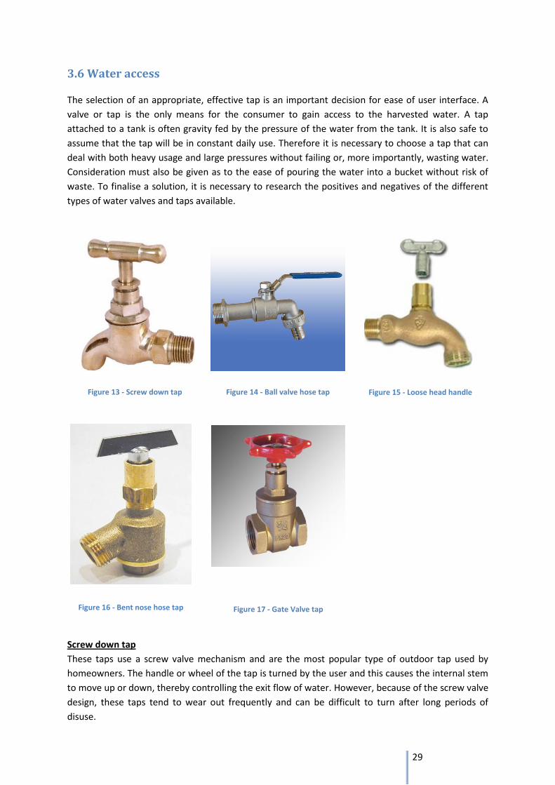
3.6 Water access
The selection of an appropriate, effective tap is an important decision for ease of user interface. A
valve or tap is the only means for the consumer to gain access to the harvested water. A tap
attached to a tank is often gravity fed by the pressure of the water from the tank. It is also safe to
assume that the tap will be in constant daily use. Therefore it is necessary to choose a tap that can
deal with both heavy usage and large pressures without failing or, more importantly, wasting water.
Consideration must also be given as to the ease of pouring the water into a bucket without risk of
waste. To finalise a solution, it is necessary to research the positives and negatives of the different
types of water valves and taps available.
Screw down tap
These taps use a screw valve mechanism and are the most popular type of outdoor tap used by
homeowners. The handle or wheel of the tap is turned by the user and this causes the internal stem
to move up or down, thereby controlling the exit flow of water. However, because of the screw valve
design, these taps tend to wear out frequently and can be difficult to turn after long periods of
disuse.
Figure 13 - Screw down tap Figure 14 - Ball valve hose tap Figure 15 - Loose head handle
Figure 17 - Gate Valve tap Figure 16 - Bent nose hose tap
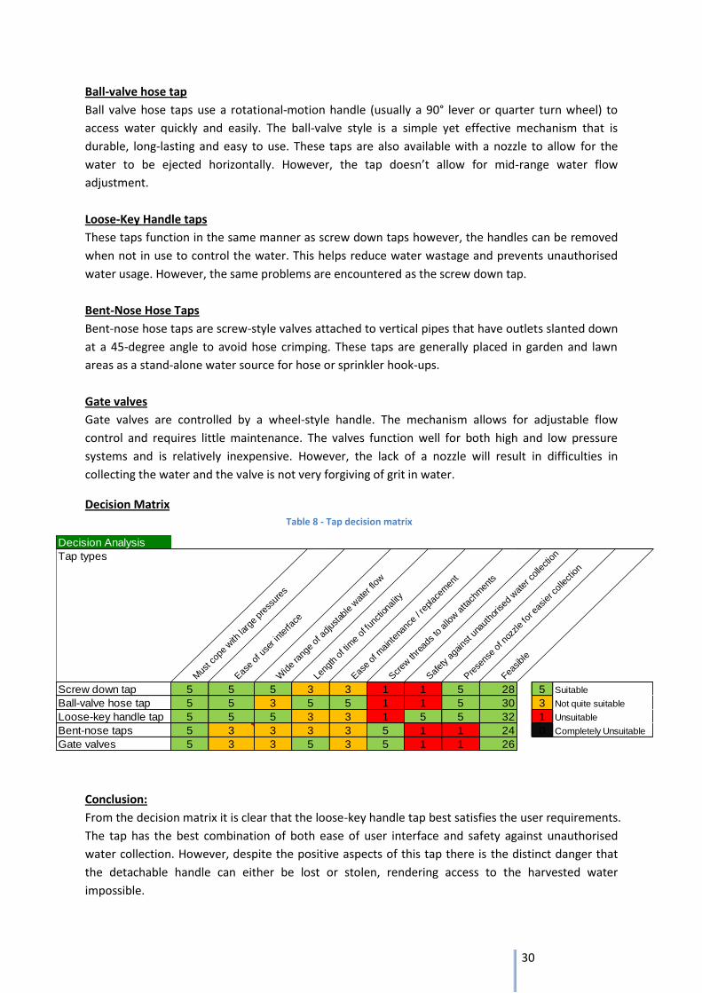
30
Decision Analysis
Tap types
Mus
t cop
e with
larg
e pr
essu
res
Eas
e of
use
r int
erfa
ce
Wid
e ra
nge
of a
djus
tabl
e wat
er fl
ow
Leng
th o
f tim
e of
func
tiona
lity
Eas
e of
maint
enan
ce /
replac
emen
t
Scr
ew th
read
s to
allo
w a
ttach
men
ts
Saf
ety
agains
t una
utho
rised
wat
er colle
ctio
n
Pre
sens
e of
noz
zle
for e
asie
r col
lect
ion
Feasibl
e
Screw down tap 5 5 5 3 3 1 1 5 28 5 Suitable
Ball-valve hose tap 5 5 3 5 5 1 1 5 30 3 Not quite suitable
Loose-key handle tap 5 5 5 3 3 1 5 5 32 1 Unsuitable
Bent-nose taps 5 3 3 3 3 5 1 1 24 0 Completely Unsuitable
Gate valves 5 3 3 5 3 5 1 1 26
Ball-valve hose tap
Ball valve hose taps use a rotational-motion handle (usually a 90° lever or quarter turn wheel) to
access water quickly and easily. The ball-valve style is a simple yet effective mechanism that is
durable, long-lasting and easy to use. These taps are also available with a nozzle to allow for the
water to be ejected horizontally. However, the tap doesn’t allow for mid-range water flow
adjustment.
Loose-Key Handle taps
These taps function in the same manner as screw down taps however, the handles can be removed
when not in use to control the water. This helps reduce water wastage and prevents unauthorised
water usage. However, the same problems are encountered as the screw down tap.
Bent-Nose Hose Taps
Bent-nose hose taps are screw-style valves attached to vertical pipes that have outlets slanted down
at a 45-degree angle to avoid hose crimping. These taps are generally placed in garden and lawn
areas as a stand-alone water source for hose or sprinkler hook-ups.
Gate valves
Gate valves are controlled by a wheel-style handle. The mechanism allows for adjustable flow
control and requires little maintenance. The valves function well for both high and low pressure
systems and is relatively inexpensive. However, the lack of a nozzle will result in difficulties in
collecting the water and the valve is not very forgiving of grit in water.
Decision Matrix
Conclusion:
From the decision matrix it is clear that the loose-key handle tap best satisfies the user requirements.
The tap has the best combination of both ease of user interface and safety against unauthorised
water collection. However, despite the positive aspects of this tap there is the distinct danger that
the detachable handle can either be lost or stolen, rendering access to the harvested water
impossible.
Table 8 - Tap decision matrix
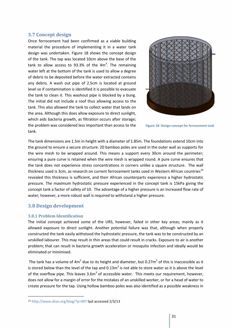
31
3.7 Concept design Once ferrocement had been confirmed as a viable building
material the procedure of implementing it in a water tank
design was undertaken. Figure 18 shows the concept design
of the tank. The tap was located 10cm above the base of the
tank to allow access to 93.3% of the 4m3. The remaining
water left at the bottom of the tank is used to allow a degree
of debris to be deposited before the water extracted contains
any debris. A wash out pipe of 2.5cm is located at ground
level so if contamination is identified it is possible to evacuate
the tank to clean it. This washout pipe is blocked by a bung.
The initial did not include a roof thus allowing access to the
tank. This also allowed the tank to collect water that lands on
the area. Although this does allow exposure to direct sunlight,
which aids bacteria growth, as filtration occurs after storage;
the problem was considered less important than access to the
tank.
The tank dimensions are 1.5m in height with a diameter of 1.85m. The foundations extend 10cm into
the ground to ensure a secure structure. 20 bamboo poles are used in the outer wall as supports for
the wire mesh to be wrapped around. This means a support every 30cm around the perimeter;
ensuring a pure curve is retained when the wire mesh is wrapped round. A pure curve ensures that
the tank does not experience stress concentrations in corners unlike a square structure. The wall
thickness used is 3cm, as research on current ferrocement tanks used in Western African countries16
revealed this thickness is sufficient, and their African counterparts experience a higher hydrostatic
pressure. The maximum hydrostatic pressure experienced in the concept tank is 15kPa giving the
concept tank a factor of safety of 10. The advantage of a higher pressure is an increased flow rate of
water; however, a more robust wall is required to withstand a higher pressure.
3.8 Design development
3.8.1 Problem Identification
The initial concept achieved some of the URS, however, failed in other key areas; mainly as it
allowed exposure to direct sunlight. Another potential failure was that, although when properly
constructed the tank easily withstood the hydrostatic pressure, the tank was to be constructed by an
unskilled labourer. This may result in thin areas that could result in cracks. Exposure to air is another
problem; that can result in bacteria growth acceleration or mosquito infection and ideally would be
eliminated or minimised.
The tank has a volume of 4m3 due to its height and diameter, but 0.27m3 of this is inaccessible as it
is stored below than the level of the tap and 0.13m3 is not able to store water as it is above the level
of the overflow pipe. This leaves 3.6m3 of accessible water. This meets our requirement, however,
does not allow for a margin of error for the mistakes of an unskilled worker, or for a head of water to
create pressure for the tap. Using hollow bamboo poles was also identified as a possible weakness in
16 http://www.akvo.org/blog/?p=997 last accessed 2/3/13
Figure 18- Design concept for ferrocement tank
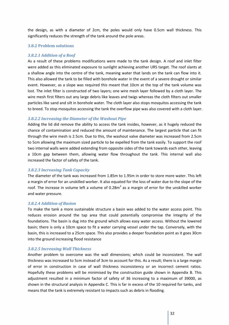
32
the design, as with a diameter of 2cm, the poles would only have 0.5cm wall thickness. This
significantly reduces the strength of the tank around the pole areas.
3.8.2 Problem solutions
3.8.2.1 Addition of a Roof
As a result of these problems modifications were made to the tank design. A roof and inlet filter
were added as this eliminated exposure to sunlight achieving another URS target. The roof slants at
a shallow angle into the centre of the tank, meaning water that lands on the tank can flow into it.
This also allowed the tank to be filled with borehole water in the event of a severe drought or similar
event. However, as a slope was required this meant that 10cm at the top of the tank volume was
lost. The inlet filter is constructed of two layers; one wire mesh layer followed by a cloth layer. The
wire mesh first filters out any large debris like leaves and twigs whereas the cloth filters out smaller
particles like sand and silt in borehole water. The cloth layer also stops mosquitos accessing the tank
to breed. To stop mosquitos accessing the tank the overflow pipe was also covered with a cloth layer.
3.8.2.2 Increasing the Diameter of the Washout Pipe
Adding the lid did remove the ability to access the tank insides, however, as it hugely reduced the
chance of contamination and reduced the amount of maintenance. The largest particle that can fit
through the wire mesh is 2.5cm. Due to this, the washout valve diameter was increased from 2.5cm
to 5cm allowing the maximum sized particle to be expelled from the tank easily. To support the roof
two internal walls were added extending from opposite sides of the tank towards each other, leaving
a 10cm gap between them, allowing water flow throughout the tank. This internal wall also
increased the factor of safety of the tank.
3.8.2.3 Increasing Tank Capacity
The diameter of the tank was increased from 1.85m to 1.95m in order to store more water. This left
a margin of error for an unskilled worker. It also equated for the loss of water due to the slope of the
roof. The increase in volume left a volume of 0.28m3 as a margin of error for the unskilled worker
and water pressure.
3.8.2.4 Addition of Basion
To make the tank a more sustainable structure a basin was added to the water access point. This
reduces erosion around the tap area that could potentially compromise the integrity of the
foundations. The basin is dug into the ground which allows easy water access. Without the lowered
basin; there is only a 10cm space to fit a water carrying vessel under the tap. Conversely, with the
basin, this is increased to a 25cm space. This also provides a deeper foundation point as it goes 30cm
into the ground increasing flood resistance
3.8.2.5 Increasing Wall Thickness
Another problem to overcome was the wall dimensions; which could be inconsistent. The wall
thickness was increased to 5cm instead of 3cm to account for this. As a result; there is a large margin
of error in construction in case of wall thickness inconsistency or an incorrect cement ratios.
Hopefully these problems will be minimised by the construction guide shown in Appendix B. This
adjustment resulted in a minimum factor of safety of 36 increasing to a maximum of 39000, as
shown in the structural analysis in Appendix C. This is far in excess of the 10 required for tanks, and
means that the tank is extremely resistant to impacts such as debris in flooding.
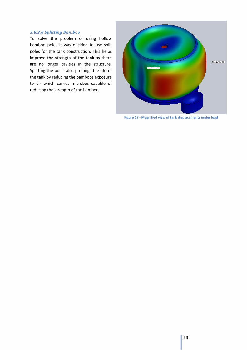
33
3.8.2.6 Splitting Bamboo
To solve the problem of using hollow
bamboo poles it was decided to use split
poles for the tank construction. This helps
improve the strength of the tank as there
are no longer cavities in the structure.
Splitting the poles also prolongs the life of
the tank by reducing the bamboos exposure
to air which carries microbes capable of
reducing the strength of the bamboo.
Figure 19 - Magnified view of tank displacements under load
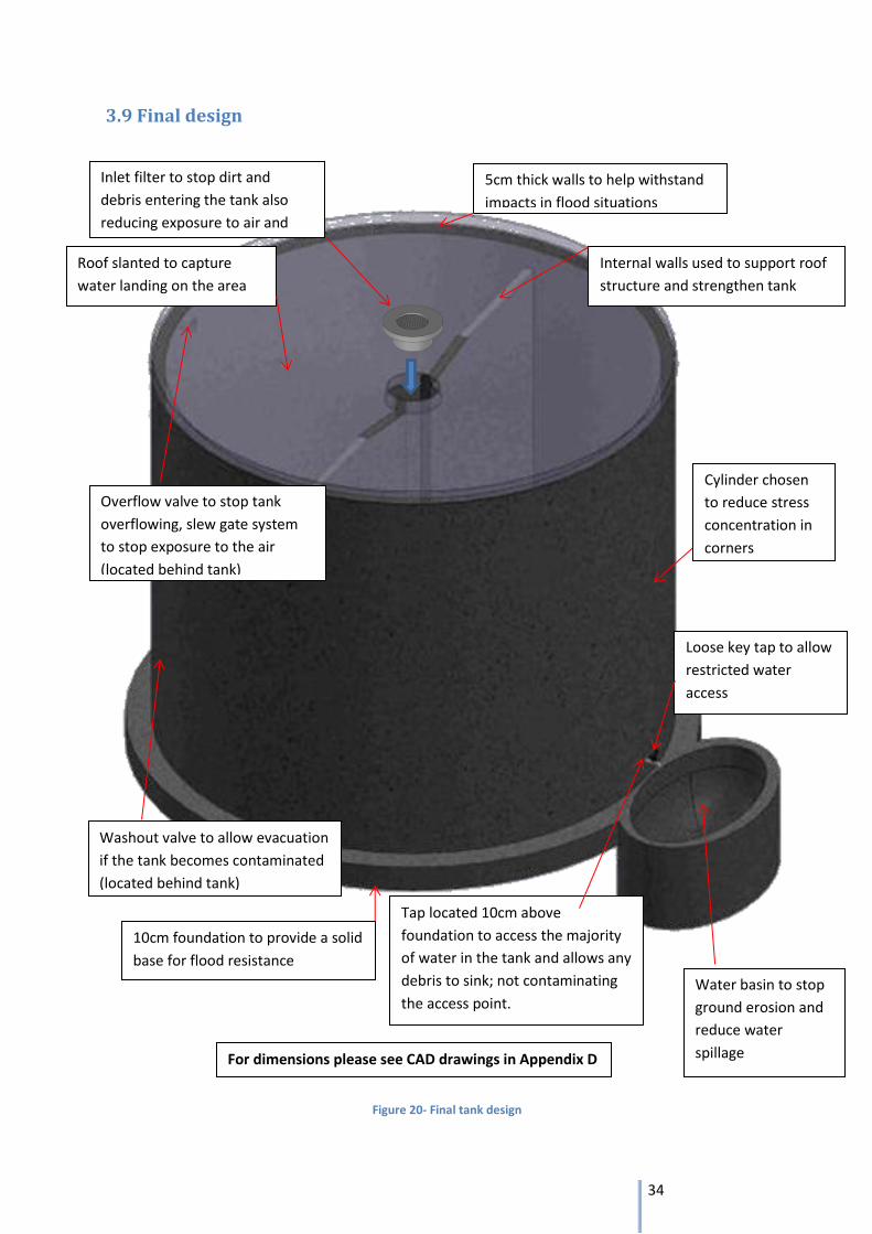
34
3.9 Final design
Washout valve to allow evacuation
if the tank becomes contaminated
(located behind tank)
Overflow valve to stop tank
overflowing, slew gate system
to stop exposure to the air
(located behind tank)
Inlet filter to stop dirt and
debris entering the tank also
reducing exposure to air and
sunlight
5cm thick walls to help withstand
impacts in flood situations
Loose key tap to allow
restricted water
access
10cm foundation to provide a solid
base for flood resistance
Water basin to stop
ground erosion and
reduce water
spillage
Roof slanted to capture
water landing on the area
Internal walls used to support roof
structure and strengthen tank
Cylinder chosen
to reduce stress
concentration in
corners
Tap located 10cm above
foundation to access the majority
of water in the tank and allows any
debris to sink; not contaminating
the access point.
Figure 20- Final tank design
For dimensions please see CAD drawings in Appendix D
35
3.10 Structural Analysis:
The stress analysis of the ferrocement water tank is of critical importance to the success of the
project. If the design fails to cope with the considerable internal hydrostatic pressure then it would
be entirely unfeasible to construct the tank.
The model program used for analysis is SolidWorks Simulation and this report summarizes the
stress analysis results of the water tank simulation. The stress analysis report can be found in
Appendix C.
3.10.1 Analytical Conclusion:
From the stress analysis report, the factor of safety for the tank under the Max von Mises stress
ranges from a minimum of 30 to a maximum of 39000. These values were calculated using a
uniformly distributed pressure within the tank of 15 kPa; the maximum hydrostatic pressure
experienced at the bottom of the tank at full capacity. The safety factor range is far in excess of
what is required to create a water tank, however, as the tank is constructed by an unskilled
worker, this margin of error is required to make up for any mistakes of procedural errors in the
manufacturing process. It is therefore safe to assume that the structure of the tank will not fail
under full capacity and can therefore be constructed.
3.11 Inlet filter
In the URS, one of the requirements was to avoid exposure to sunlight and fresh air. To achieve this,
yet still have the ability for water to pour in through the top of the tank, a special inlet filter has
been designed.
This simple, small, removable device is aimed at preventing mosquitoes and debris from entering the
tank. It includes the same wire mesh used in the walls of tank but here, as a sieve; to remove large
debris. Then, wrapped around the bottom, some cloth/nylon to act as a porous membrane –
allowing water flow, but not silt, dirt or mosquitoes. Combined, these two filters will prevent most
non-microscopic contaminants from entering the tank.
The device is designed to sit in the hole at the top of the tank,
and to be removable when required. Either to remove debris
from the filter or possibly replace the cloth when required.
One of the advantages of this design, is that it can be
constructed with the waste materials from the tank
construction; wire mesh cut-offs and spare cement are all that is
needed to build it.
3.12 Sustainable storage
3.12.1 Life span of Tank
The sustainability of the tank is based on the long working life and minimal damage to the area
around the tank. The tank has a life span of over 20 years; this is due to the construction techniques
used. The material used most susceptible to failure is the bamboo struts; which have a life span of
10 years when they are not in contact with the soil. In our construction, the bamboo is completely
encased in cement which increases the working life of the bamboo. This is achieved by eliminating
Figure 21 - CAD drawing of inlet filter
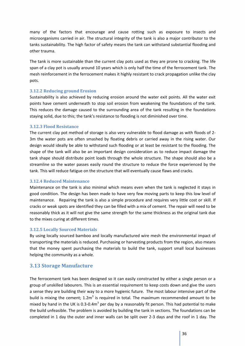
36
many of the factors that encourage and cause rotting such as exposure to insects and
microorganisms carried in air. The structural integrity of the tank is also a major contributor to the
tanks sustainability. The high factor of safety means the tank can withstand substantial flooding and
other trauma.
The tank is more sustainable than the current clay pots used as they are prone to cracking. The life
span of a clay pot is usually around 10 years which is only half the time of the ferrocement tank. The
mesh reinforcement in the ferrocement makes it highly resistant to crack propagation unlike the clay
pots.
3.12.2 Reducing ground Erosion
Sustainability is also achieved by reducing erosion around the water exit points. All the water exit
points have cement underneath to stop soil erosion from weakening the foundations of the tank.
This reduces the damage caused to the surrounding area of the tank resulting in the foundations
staying solid, due to this; the tank’s resistance to flooding is not diminished over time.
3.12.3 Flood Resistance
The current clay pot method of storage is also very vulnerable to flood damage as with floods of 2-
3m the water pots are often smashed by floating debris or carried away in the rising water. Our
design would ideally be able to withstand such flooding or at least be resistant to the flooding. The
shape of the tank will also be an important design consideration as to reduce impact damage the
tank shape should distribute point loads through the whole structure. The shape should also be a
streamline so the water passes easily round the structure to reduce the force experienced by the
tank. This will reduce fatigue on the structure that will eventually cause flaws and cracks.
3.12.4 Reduced Maintenance
Maintenance on the tank is also minimal which means even when the tank is neglected it stays in
good condition. The design has been made to have very few moving parts to keep this low level of
maintenance. Repairing the tank is also a simple procedure and requires very little cost or skill. If
cracks or weak spots are identified they can be filled with a mix of cement. The repair will need to be
reasonably thick as it will not give the same strength for the same thickness as the original tank due
to the mixes curing at different times.
3.12.5 Locally Sourced Materials
By using locally sourced bamboo and locally manufactured wire mesh the environmental impact of
transporting the materials is reduced. Purchasing or harvesting products from the region, also means
that the money spent purchasing the materials to build the tank, support small local businesses
helping the community as a whole.
3.13 Storage Manufacture
The ferrocement tank has been designed so it can easily constructed by either a single person or a
group of unskilled labourers. This is an essential requirement to keep costs down and give the users
a sense they are building their way to a more hygienic future. The most labour intensive part of the
build is mixing the cement; 1.2m3 is required in total. The maximum recommended amount to be
mixed by hand in the UK is 0.3-0.4m3 per day by a reasonably fit person. This had potential to make
the build unfeasible. The problem is avoided by building the tank in sections. The foundations can be
completed in 1 day the outer and inner walls can be split over 2-3 days and the roof in 1 day. The
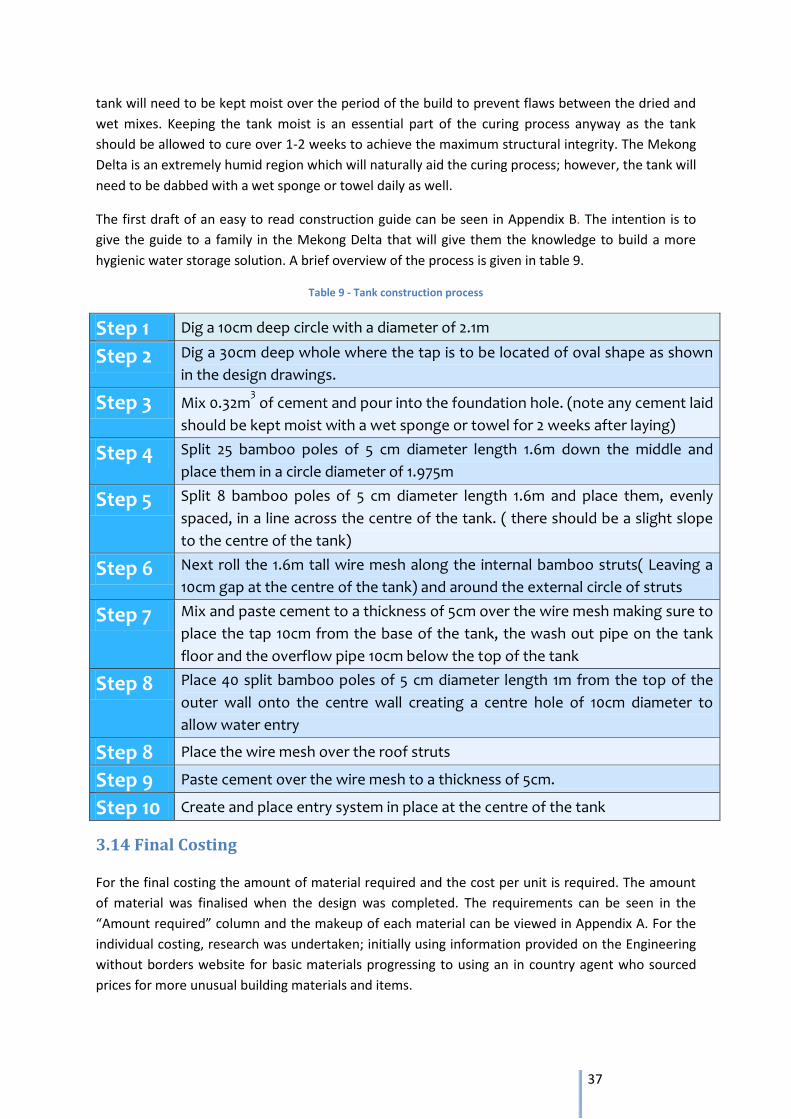
37
tank will need to be kept moist over the period of the build to prevent flaws between the dried and
wet mixes. Keeping the tank moist is an essential part of the curing process anyway as the tank
should be allowed to cure over 1-2 weeks to achieve the maximum structural integrity. The Mekong
Delta is an extremely humid region which will naturally aid the curing process; however, the tank will
need to be dabbed with a wet sponge or towel daily as well.
The first draft of an easy to read construction guide can be seen in Appendix B. The intention is to
give the guide to a family in the Mekong Delta that will give them the knowledge to build a more
hygienic water storage solution. A brief overview of the process is given in table 9.
Table 9 - Tank construction process
Step 1 Dig a 10cm deep circle with a diameter of 2.1m
Step 2 Dig a 30cm deep whole where the tap is to be located of oval shape as shown
in the design drawings.
Step 3 Mix 0.32m3 of cement and pour into the foundation hole. (note any cement laid
should be kept moist with a wet sponge or towel for 2 weeks after laying)
Step 4 Split 25 bamboo poles of 5 cm diameter length 1.6m down the middle and
place them in a circle diameter of 1.975m
Step 5 Split 8 bamboo poles of 5 cm diameter length 1.6m and place them, evenly
spaced, in a line across the centre of the tank. ( there should be a slight slope
to the centre of the tank)
Step 6 Next roll the 1.6m tall wire mesh along the internal bamboo struts( Leaving a
10cm gap at the centre of the tank) and around the external circle of struts
Step 7 Mix and paste cement to a thickness of 5cm over the wire mesh making sure to
place the tap 10cm from the base of the tank, the wash out pipe on the tank
floor and the overflow pipe 10cm below the top of the tank
Step 8 Place 40 split bamboo poles of 5 cm diameter length 1m from the top of the
outer wall onto the centre wall creating a centre hole of 10cm diameter to
allow water entry
Step 8 Place the wire mesh over the roof struts
Step 9 Paste cement over the wire mesh to a thickness of 5cm.
Step 10 Create and place entry system in place at the centre of the tank
3.14 Final Costing
For the final costing the amount of material required and the cost per unit is required. The amount
of material was finalised when the design was completed. The requirements can be seen in the
“Amount required” column and the makeup of each material can be viewed in Appendix A. For the
individual costing, research was undertaken; initially using information provided on the Engineering
without borders website for basic materials progressing to using an in country agent who sourced
prices for more unusual building materials and items.
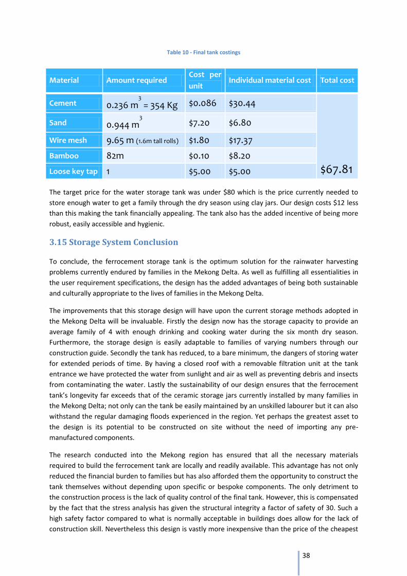
38
Table 10 - Final tank costings
The target price for the water storage tank was under $80 which is the price currently needed to
store enough water to get a family through the dry season using clay jars. Our design costs $12 less
than this making the tank financially appealing. The tank also has the added incentive of being more
robust, easily accessible and hygienic.
3.15 Storage System Conclusion
To conclude, the ferrocement storage tank is the optimum solution for the rainwater harvesting
problems currently endured by families in the Mekong Delta. As well as fulfilling all essentialities in
the user requirement specifications, the design has the added advantages of being both sustainable
and culturally appropriate to the lives of families in the Mekong Delta.
The improvements that this storage design will have upon the current storage methods adopted in
the Mekong Delta will be invaluable. Firstly the design now has the storage capacity to provide an
average family of 4 with enough drinking and cooking water during the six month dry season.
Furthermore, the storage design is easily adaptable to families of varying numbers through our
construction guide. Secondly the tank has reduced, to a bare minimum, the dangers of storing water
for extended periods of time. By having a closed roof with a removable filtration unit at the tank
entrance we have protected the water from sunlight and air as well as preventing debris and insects
from contaminating the water. Lastly the sustainability of our design ensures that the ferrocement
tank’s longevity far exceeds that of the ceramic storage jars currently installed by many families in
the Mekong Delta; not only can the tank be easily maintained by an unskilled labourer but it can also
withstand the regular damaging floods experienced in the region. Yet perhaps the greatest asset to
the design is its potential to be constructed on site without the need of importing any pre-
manufactured components.
The research conducted into the Mekong region has ensured that all the necessary materials
required to build the ferrocement tank are locally and readily available. This advantage has not only
reduced the financial burden to families but has also afforded them the opportunity to construct the
tank themselves without depending upon specific or bespoke components. The only detriment to
the construction process is the lack of quality control of the final tank. However, this is compensated
by the fact that the stress analysis has given the structural integrity a factor of safety of 30. Such a
high safety factor compared to what is normally acceptable in buildings does allow for the lack of
construction skill. Nevertheless this design is vastly more inexpensive than the price of the cheapest
Material Amount required Cost per
unit Individual material cost Total cost
Cement 0.236 m3
= 354 Kg $0.086 $30.44
$67.81
Sand 0.944 m3
$7.20 $6.80
Wire mesh 9.65 m (1.6m tall rolls) $1.80 $17.37
Bamboo 82m $0.10 $8.20
Loose key tap 1 $5.00 $5.00
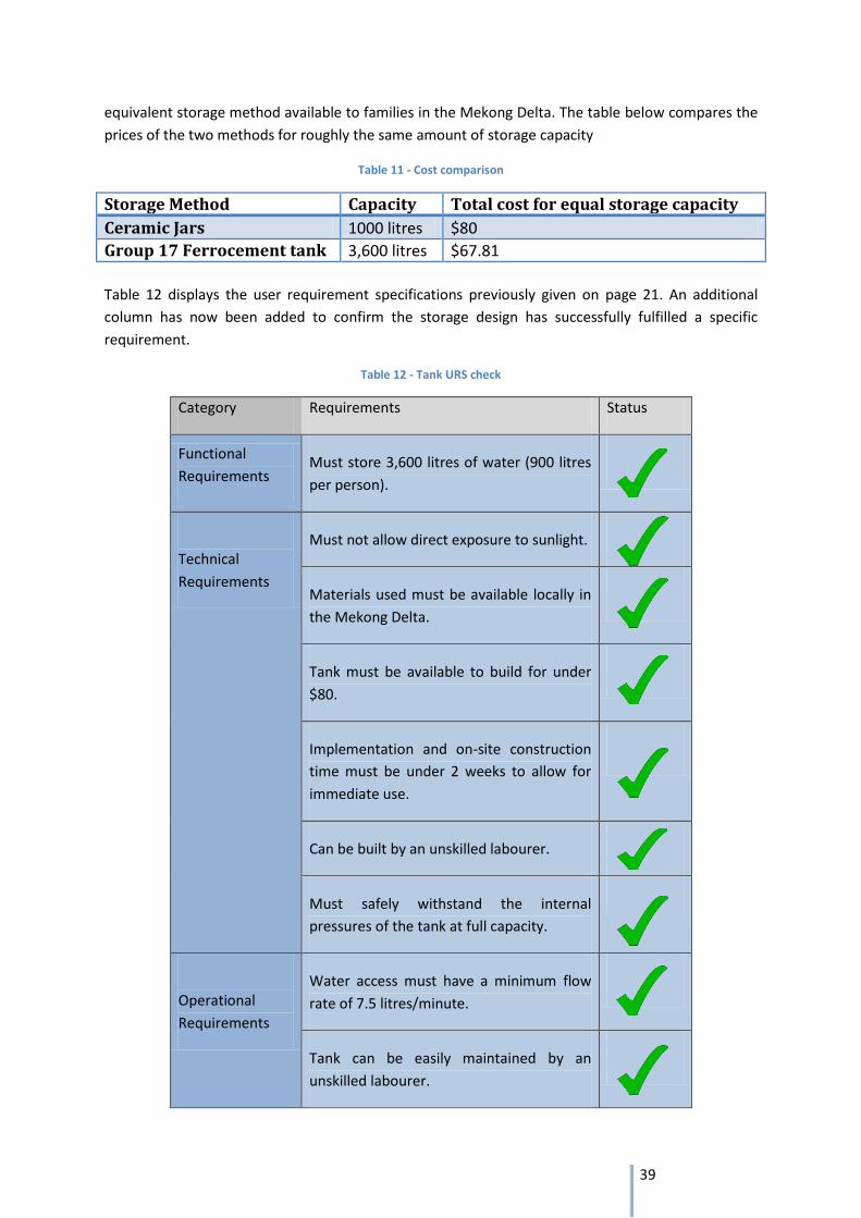
39
equivalent storage method available to families in the Mekong Delta. The table below compares the
prices of the two methods for roughly the same amount of storage capacity
Table 11 - Cost comparison
Storage Method Capacity Total cost for equal storage capacity
Ceramic Jars 1000 litres $80
Group 17 Ferrocement tank 3,600 litres $67.81
Table 12 displays the user requirement specifications previously given on page 21. An additional
column has now been added to confirm the storage design has successfully fulfilled a specific
requirement.
Table 12 - Tank URS check
Category Requirements Status
Functional
Requirements Must store 3,600 litres of water (900 litres
per person).
Technical
Requirements
Must not allow direct exposure to sunlight.
Materials used must be available locally in
the Mekong Delta.
Tank must be available to build for under
$80.
Implementation and on-site construction
time must be under 2 weeks to allow for
immediate use.
Can be built by an unskilled labourer.
Must safely withstand the internal
pressures of the tank at full capacity.
Operational
Requirements
Water access must have a minimum flow
rate of 7.5 litres/minute.
Tank can be easily maintained by an
unskilled labourer.
40
Water Filtration
Callum Stephen & Nicholas Sidwell
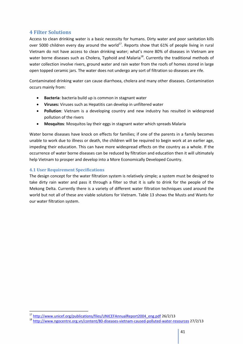
41
4 Filter Solutions Access to clean drinking water is a basic necessity for humans. Dirty water and poor sanitation kills
over 5000 children every day around the world17. Reports show that 61% of people living in rural
Vietnam do not have access to clean drinking water; what’s more 80% of diseases in Vietnam are
water borne diseases such as Cholera, Typhoid and Malaria18. Currently the traditional methods of
water collection involve rivers, ground water and rain water from the roofs of homes stored in large
open topped ceramic jars. The water does not undergo any sort of filtration so diseases are rife.
Contaminated drinking water can cause diarrhoea, cholera and many other diseases. Contamination
occurs mainly from:
Bacteria: bacteria build up is common in stagnant water
Viruses: Viruses such as Hepatitis can develop in unfiltered water
Pollution: Vietnam is a developing country and new industry has resulted in widespread
pollution of the rivers
Mosquitos: Mosquitos lay their eggs in stagnant water which spreads Malaria
Water borne diseases have knock on effects for families; if one of the parents in a family becomes
unable to work due to illness or death, the children will be required to begin work at an earlier age,
impeding their education. This can have more widespread effects on the country as a whole. If the
occurrence of water borne diseases can be reduced by filtration and education then it will ultimately
help Vietnam to prosper and develop into a More Economically Developed Country.
4.1 User Requirement Specifications
The design concept for the water filtration system is relatively simple; a system must be designed to
take dirty rain water and pass it through a filter so that it is safe to drink for the people of the
Mekong Delta. Currently there is a variety of different water filtration techniques used around the
world but not all of these are viable solutions for Vietnam. Table 13 shows the Musts and Wants for
our water filtration system.
17
http://www.unicef.org/publications/files/UNICEFAnnualReport2004_eng.pdf 26/2/13 18
http://www.ngocentre.org.vn/content/80-diseases-vietnam-caused-polluted-water-resources 27/2/13
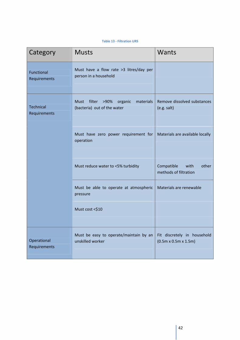
42
Table 13 - Filtration URS
Category Musts Wants
Functional
Requirements
Must have a flow rate >3 litres/day per
person in a household
Technical
Requirements
Must filter >90% organic materials
(bacteria) out of the water
Remove dissolved substances
(e.g. salt)
Must have zero power requirement for
operation
Materials are available locally
Must reduce water to <5% turbidity Compatible with other
methods of filtration
Must be able to operate at atmospheric
pressure
Materials are renewable
Must cost <$10
Operational
Requirements
Must be easy to operate/maintain by an
unskilled worker
Fit discretely in household
(0.5m x 0.5m x 1.5m)
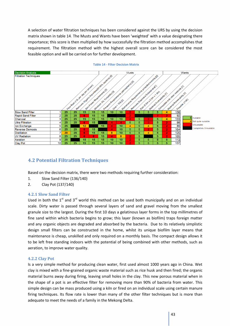
43
A selection of water filtration techniques has been considered against the URS by using the decision
matrix shown in table 14. The Musts and Wants have been ‘weighted’ with a value designating there
importance; this score is then multiplied by how successfully the filtration method accomplishes that
requirement. The filtration method with the highest overall score can be considered the most
feasible option and will be carried on for further development.
4.2 Potential Filtration Techniques
Based on the decision matrix, there were two methods requiring further consideration:
1. Slow Sand Filter (136/140)
2. Clay Pot (137/140)
4.2.1 Slow Sand Filter
Used in both the 1st and 3rd world this method can be used both municipally and on an individual
scale. Dirty water is passed through several layers of sand and gravel moving from the smallest
granule size to the largest. During the first 10 days a gelatinous layer forms in the top millimetres of
fine sand within which bacteria begins to grow; this layer (known as biofilm) traps foreign matter
and any organic objects are degraded and absorbed by the bacteria. Due to its relatively simplistic
design small filters can be constructed in the home, whilst its unique biofilm layer means that
maintenance is cheap, unskilled and only required on a monthly basis. The compact design allows it
to be left free standing indoors with the potential of being combined with other methods, such as
aeration, to improve water quality.
4.2.2 Clay Pot
Is a very simple method for producing clean water, first used almost 1000 years ago in China. Wet
clay is mixed with a fine-grained organic waste material such as rice husk and then fired; the organic
material burns away during firing, leaving small holes in the clay. This new porous material when in
the shape of a pot is an effective filter for removing more than 90% of bacteria from water. This
simple design can be mass produced using a kiln or fired on an individual scale using certain manure
firing techniques. Its flow rate is lower than many of the other filter techniques but is more than
adequate to meet the needs of a family in the Mekong Delta.
Table 14 - Filter Decision Matrix
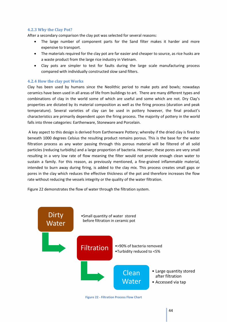
44
4.2.3 Why the Clay Pot?
After a secondary comparison the clay pot was selected for several reasons:
The large number of component parts for the Sand filter makes it harder and more
expensive to transport.
The materials required for the clay pot are far easier and cheaper to source, as rice husks are
a waste product from the large rice industry in Vietnam.
Clay pots are simpler to test for faults during the large scale manufacturing process
compared with individually constructed slow sand filters.
4.2.4 How the clay pot Works
Clay has been used by humans since the Neolithic period to make pots and bowls; nowadays
ceramics have been used in all areas of life from buildings to art. There are many different types and
combinations of clay in the world some of which are useful and some which are not. Dry Clay’s
properties are dictated by its material composition as well as the firing process (duration and peak
temperature). Several varieties of clay can be used in pottery however, the final product’s
characteristics are primarily dependent upon the firing process. The majority of pottery in the world
falls into three categories: Earthenware, Stoneware and Porcelain.
A key aspect to this design is derived from Earthenware Pottery; whereby if the dried clay is fired to
beneath 1000 degrees Celsius the resulting product remains porous. This is the base for the water
filtration process as any water passing through this porous material will be filtered of all solid
particles (reducing turbidity) and a large proportion of bacteria. However, these pores are very small
resulting in a very low rate of flow meaning the filter would not provide enough clean water to
sustain a family. For this reason, as previously mentioned, a fine-grained inflammable material,
intended to burn away during firing, is added to the clay mix. This process creates small gaps or
pores in the clay which reduces the effective thickness of the pot and therefore increases the flow
rate without reducing the vessels integrity or the quality of the water filtration.
Figure 22 demonstrates the flow of water through the filtration system.
Figure 22 - Filtration Process Flow Chart
Dirty Water
•Small quantity of water stored before filtration in ceramic pot
Filtration •>90% of bacteria removed
•Turbidity reduced to <5%
Clean Water
• Large quantity stored after filtration
• Accessed via tap
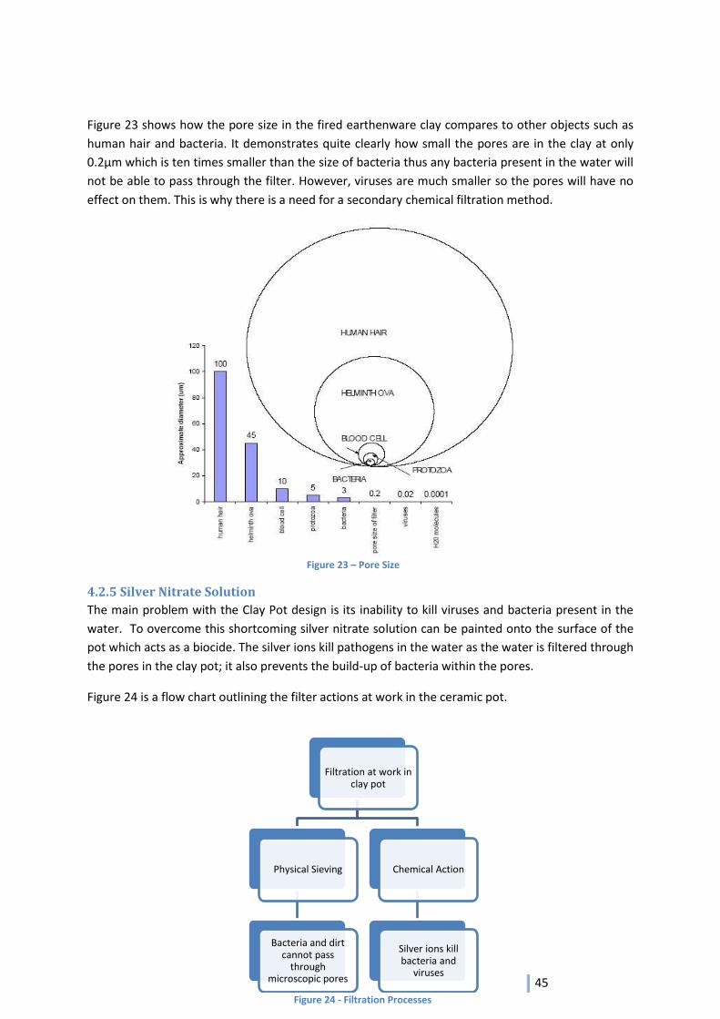
45
Figure 23 shows how the pore size in the fired earthenware clay compares to other objects such as
human hair and bacteria. It demonstrates quite clearly how small the pores are in the clay at only
0.2μm which is ten times smaller than the size of bacteria thus any bacteria present in the water will
not be able to pass through the filter. However, viruses are much smaller so the pores will have no
effect on them. This is why there is a need for a secondary chemical filtration method.
4.2.5 Silver Nitrate Solution
The main problem with the Clay Pot design is its inability to kill viruses and bacteria present in the
water. To overcome this shortcoming silver nitrate solution can be painted onto the surface of the
pot which acts as a biocide. The silver ions kill pathogens in the water as the water is filtered through
the pores in the clay pot; it also prevents the build-up of bacteria within the pores.
Figure 24 is a flow chart outlining the filter actions at work in the ceramic pot.
Filtration at work in clay pot
Physical Sieving
Bacteria and dirt cannot pass
through microscopic pores
Chemical Action
Silver ions kill bacteria and
viruses
Figure 23 – Pore Size
Figure 24 - Filtration Processes
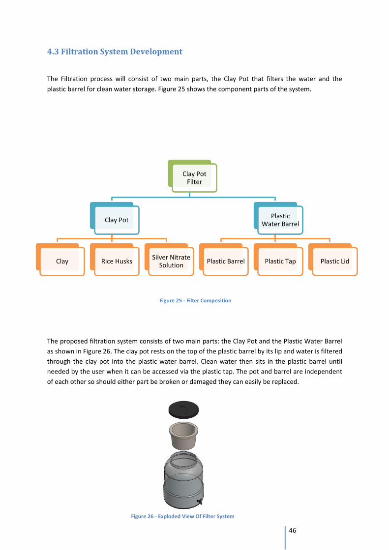
46
4.3 Filtration System Development
The Filtration process will consist of two main parts, the Clay Pot that filters the water and the
plastic barrel for clean water storage. Figure 25 shows the component parts of the system.
The proposed filtration system consists of two main parts: the Clay Pot and the Plastic Water Barrel
as shown in Figure 26. The clay pot rests on the top of the plastic barrel by its lip and water is filtered
through the clay pot into the plastic water barrel. Clean water then sits in the plastic barrel until
needed by the user when it can be accessed via the plastic tap. The pot and barrel are independent
of each other so should either part be broken or damaged they can easily be replaced.
Clay Pot Filter
Clay Pot
Clay Rice Husks Silver Nitrate
Solution
Plastic Water Barrel
Plastic Barrel Plastic Tap Plastic Lid
Figure 25 - Filter Composition
Figure 26 - Exploded View Of Filter System
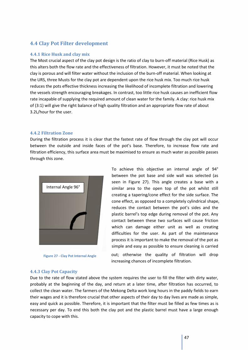
47
4.4 Clay Pot Filter development
4.4.1 Rice Husk and clay mix
The Most crucial aspect of the clay pot design is the ratio of clay to burn-off material (Rice Husk) as
this alters both the flow rate and the effectiveness of filtration. However, it must be noted that the
clay is porous and will filter water without the inclusion of the burn-off material. When looking at
the URS, three Musts for the clay pot are dependent upon the rice husk mix. Too much rice husk
reduces the pots effective thickness increasing the likelihood of incomplete filtration and lowering
the vessels strength encouraging breakages. In contrast, too little rice husk causes an inefficient flow
rate incapable of supplying the required amount of clean water for the family. A clay: rice husk mix
of (3:1) will give the right balance of high quality filtration and an appropriate flow rate of about
3.2L/hour for the user.
4.4.2 Filtration Zone
During the filtration process it is clear that the fastest rate of flow through the clay pot will occur
between the outside and inside faces of the pot’s base. Therefore, to increase flow rate and
filtration efficiency, this surface area must be maximised to ensure as much water as possible passes
through this zone.
To achieve this objective an internal angle of 94°
between the pot base and side wall was selected (as
seen in Figure 27). This angle creates a base with a
similar area to the open top of the pot whilst still
creating a tapering/cone effect for the side surface. The
cone effect, as opposed to a completely cylindrical shape,
reduces the contact between the pot’s sides and the
plastic barrel’s top edge during removal of the pot. Any
contact between these two surfaces will cause friction
which can damage either unit as well as creating
difficulties for the user. As part of the maintenance
process it is important to make the removal of the pot as
simple and easy as possible to ensure cleaning is carried
out; otherwise the quality of filtration will drop
increasing chances of incomplete filtration.
4.4.3 Clay Pot Capacity
Due to the rate of flow stated above the system requires the user to fill the filter with dirty water,
probably at the beginning of the day, and return at a later time, after filtration has occurred, to
collect the clean water. The farmers of the Mekong Delta work long hours in the paddy fields to earn
their wages and it is therefore crucial that other aspects of their day to day lives are made as simple,
easy and quick as possible. Therefore, it is important that the filter must be filled as few times as is
necessary per day. To end this both the clay pot and the plastic barrel must have a large enough
capacity to cope with this.
Internal Angle 96°
Figure 27 - Clay Pot Internal Angle
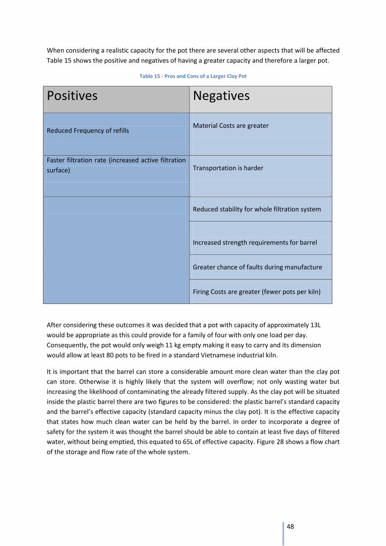
48
When considering a realistic capacity for the pot there are several other aspects that will be affected
Table 15 shows the positive and negatives of having a greater capacity and therefore a larger pot.
Table 15 - Pros and Cons of a Larger Clay Pot
Positives Negatives
Reduced Frequency of refills Material Costs are greater
Faster filtration rate (increased active filtration
surface) Transportation is harder
Reduced stability for whole filtration system
Increased strength requirements for barrel
Greater chance of faults during manufacture
Firing Costs are greater (fewer pots per kiln)
After considering these outcomes it was decided that a pot with capacity of approximately 13L
would be appropriate as this could provide for a family of four with only one load per day.
Consequently, the pot would only weigh 11 kg empty making it easy to carry and its dimension
would allow at least 80 pots to be fired in a standard Vietnamese industrial kiln.
It is important that the barrel can store a considerable amount more clean water than the clay pot
can store. Otherwise it is highly likely that the system will overflow; not only wasting water but
increasing the likelihood of contaminating the already filtered supply. As the clay pot will be situated
inside the plastic barrel there are two figures to be considered: the plastic barrel’s standard capacity
and the barrel’s effective capacity (standard capacity minus the clay pot). It is the effective capacity
that states how much clean water can be held by the barrel. In order to incorporate a degree of
safety for the system it was thought the barrel should be able to contain at least five days of filtered
water, without being emptied, this equated to 65L of effective capacity. Figure 28 shows a flow chart
of the storage and flow rate of the whole system.
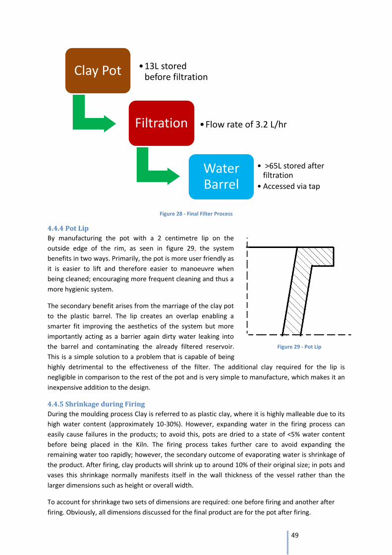
49
Figure 28 - Final Filter Process
4.4.4 Pot Lip
By manufacturing the pot with a 2 centimetre lip on the
outside edge of the rim, as seen in figure 29, the system
benefits in two ways. Primarily, the pot is more user friendly as
it is easier to lift and therefore easier to manoeuvre when
being cleaned; encouraging more frequent cleaning and thus a
more hygienic system.
The secondary benefit arises from the marriage of the clay pot
to the plastic barrel. The lip creates an overlap enabling a
smarter fit improving the aesthetics of the system but more
importantly acting as a barrier again dirty water leaking into
the barrel and contaminating the already filtered reservoir.
This is a simple solution to a problem that is capable of being
highly detrimental to the effectiveness of the filter. The additional clay required for the lip is
negligible in comparison to the rest of the pot and is very simple to manufacture, which makes it an
inexpensive addition to the design.
4.4.5 Shrinkage during Firing
During the moulding process Clay is referred to as plastic clay, where it is highly malleable due to its
high water content (approximately 10-30%). However, expanding water in the firing process can
easily cause failures in the products; to avoid this, pots are dried to a state of <5% water content
before being placed in the Kiln. The firing process takes further care to avoid expanding the
remaining water too rapidly; however, the secondary outcome of evaporating water is shrinkage of
the product. After firing, clay products will shrink up to around 10% of their original size; in pots and
vases this shrinkage normally manifests itself in the wall thickness of the vessel rather than the
larger dimensions such as height or overall width.
To account for shrinkage two sets of dimensions are required: one before firing and another after
firing. Obviously, all dimensions discussed for the final product are for the pot after firing.
Clay Pot •13L stored before filtration
Filtration •Flow rate of 3.2 L/hr
Water Barrel
• >65L stored after filtration
• Accessed via tap
Figure 29 - Pot Lip
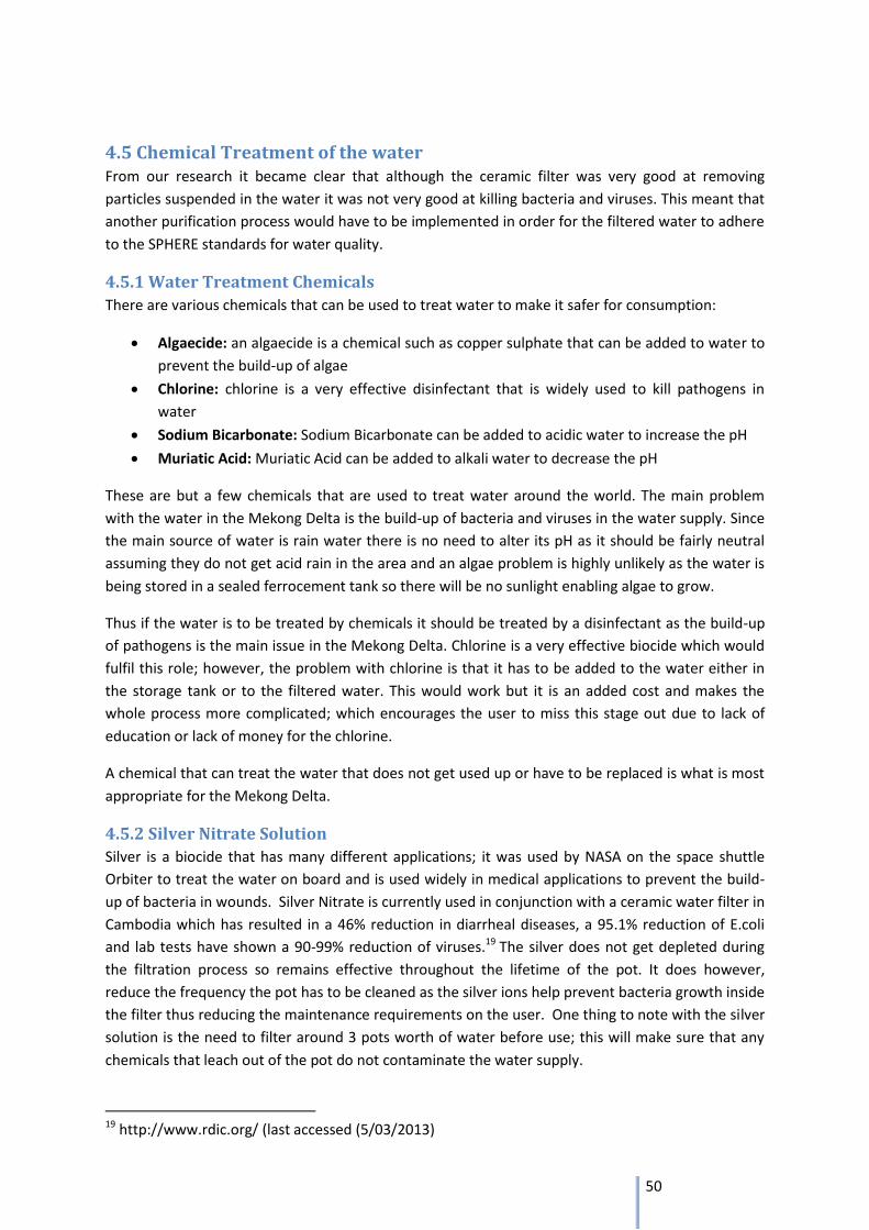
50
4.5 Chemical Treatment of the water From our research it became clear that although the ceramic filter was very good at removing
particles suspended in the water it was not very good at killing bacteria and viruses. This meant that
another purification process would have to be implemented in order for the filtered water to adhere
to the SPHERE standards for water quality.
4.5.1 Water Treatment Chemicals
There are various chemicals that can be used to treat water to make it safer for consumption:
Algaecide: an algaecide is a chemical such as copper sulphate that can be added to water to
prevent the build-up of algae
Chlorine: chlorine is a very effective disinfectant that is widely used to kill pathogens in
water
Sodium Bicarbonate: Sodium Bicarbonate can be added to acidic water to increase the pH
Muriatic Acid: Muriatic Acid can be added to alkali water to decrease the pH
These are but a few chemicals that are used to treat water around the world. The main problem
with the water in the Mekong Delta is the build-up of bacteria and viruses in the water supply. Since
the main source of water is rain water there is no need to alter its pH as it should be fairly neutral
assuming they do not get acid rain in the area and an algae problem is highly unlikely as the water is
being stored in a sealed ferrocement tank so there will be no sunlight enabling algae to grow.
Thus if the water is to be treated by chemicals it should be treated by a disinfectant as the build-up
of pathogens is the main issue in the Mekong Delta. Chlorine is a very effective biocide which would
fulfil this role; however, the problem with chlorine is that it has to be added to the water either in
the storage tank or to the filtered water. This would work but it is an added cost and makes the
whole process more complicated; which encourages the user to miss this stage out due to lack of
education or lack of money for the chlorine.
A chemical that can treat the water that does not get used up or have to be replaced is what is most
appropriate for the Mekong Delta.
4.5.2 Silver Nitrate Solution
Silver is a biocide that has many different applications; it was used by NASA on the space shuttle
Orbiter to treat the water on board and is used widely in medical applications to prevent the build-
up of bacteria in wounds. Silver Nitrate is currently used in conjunction with a ceramic water filter in
Cambodia which has resulted in a 46% reduction in diarrheal diseases, a 95.1% reduction of E.coli
and lab tests have shown a 90-99% reduction of viruses.19 The silver does not get depleted during
the filtration process so remains effective throughout the lifetime of the pot. It does however,
reduce the frequency the pot has to be cleaned as the silver ions help prevent bacteria growth inside
the filter thus reducing the maintenance requirements on the user. One thing to note with the silver
solution is the need to filter around 3 pots worth of water before use; this will make sure that any
chemicals that leach out of the pot do not contaminate the water supply.
19 http://www.rdic.org/ (last accessed (5/03/2013)
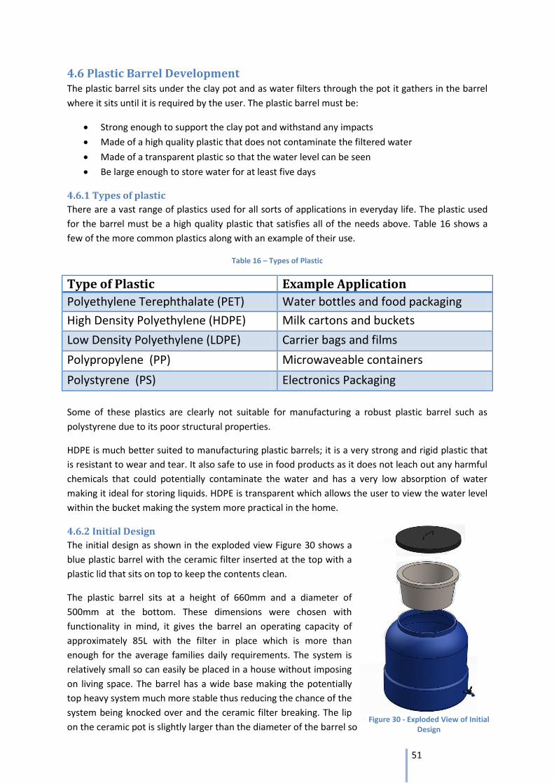
51
4.6 Plastic Barrel Development The plastic barrel sits under the clay pot and as water filters through the pot it gathers in the barrel
where it sits until it is required by the user. The plastic barrel must be:
Strong enough to support the clay pot and withstand any impacts
Made of a high quality plastic that does not contaminate the filtered water
Made of a transparent plastic so that the water level can be seen
Be large enough to store water for at least five days
4.6.1 Types of plastic
There are a vast range of plastics used for all sorts of applications in everyday life. The plastic used
for the barrel must be a high quality plastic that satisfies all of the needs above. Table 16 shows a
few of the more common plastics along with an example of their use.
Table 16 – Types of Plastic
Type of Plastic Example Application
Polyethylene Terephthalate (PET) Water bottles and food packaging
High Density Polyethylene (HDPE) Milk cartons and buckets
Low Density Polyethylene (LDPE) Carrier bags and films
Polypropylene (PP) Microwaveable containers
Polystyrene (PS) Electronics Packaging
Some of these plastics are clearly not suitable for manufacturing a robust plastic barrel such as
polystyrene due to its poor structural properties.
HDPE is much better suited to manufacturing plastic barrels; it is a very strong and rigid plastic that
is resistant to wear and tear. It also safe to use in food products as it does not leach out any harmful
chemicals that could potentially contaminate the water and has a very low absorption of water
making it ideal for storing liquids. HDPE is transparent which allows the user to view the water level
within the bucket making the system more practical in the home.
4.6.2 Initial Design
The initial design as shown in the exploded view Figure 30 shows a
blue plastic barrel with the ceramic filter inserted at the top with a
plastic lid that sits on top to keep the contents clean.
The plastic barrel sits at a height of 660mm and a diameter of
500mm at the bottom. These dimensions were chosen with
functionality in mind, it gives the barrel an operating capacity of
approximately 85L with the filter in place which is more than
enough for the average families daily requirements. The system is
relatively small so can easily be placed in a house without imposing
on living space. The barrel has a wide base making the potentially
top heavy system much more stable thus reducing the chance of the
system being knocked over and the ceramic filter breaking. The lip
on the ceramic pot is slightly larger than the diameter of the barrel so Figure 30 - Exploded View of Initial
Design
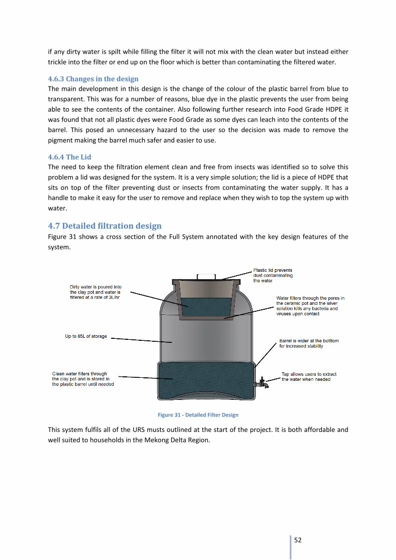
52
if any dirty water is spilt while filling the filter it will not mix with the clean water but instead either
trickle into the filter or end up on the floor which is better than contaminating the filtered water.
4.6.3 Changes in the design
The main development in this design is the change of the colour of the plastic barrel from blue to
transparent. This was for a number of reasons, blue dye in the plastic prevents the user from being
able to see the contents of the container. Also following further research into Food Grade HDPE it
was found that not all plastic dyes were Food Grade as some dyes can leach into the contents of the
barrel. This posed an unnecessary hazard to the user so the decision was made to remove the
pigment making the barrel much safer and easier to use.
4.6.4 The Lid
The need to keep the filtration element clean and free from insects was identified so to solve this
problem a lid was designed for the system. It is a very simple solution; the lid is a piece of HDPE that
sits on top of the filter preventing dust or insects from contaminating the water supply. It has a
handle to make it easy for the user to remove and replace when they wish to top the system up with
water.
4.7 Detailed filtration design Figure 31 shows a cross section of the Full System annotated with the key design features of the
system.
Figure 31 - Detailed Filter Design
This system fulfils all of the URS musts outlined at the start of the project. It is both affordable and
well suited to households in the Mekong Delta Region.
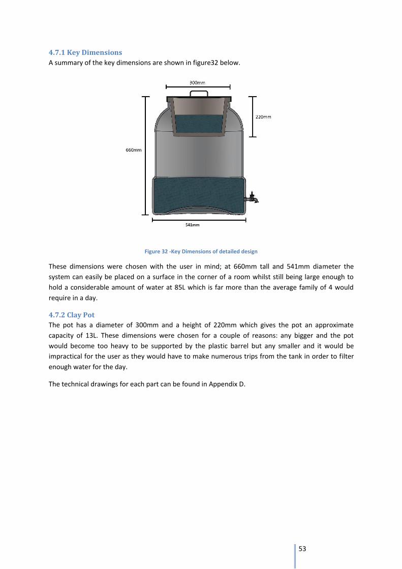
53
4.7.1 Key Dimensions
A summary of the key dimensions are shown in figure32 below.
Figure 32 -Key Dimensions of detailed design
These dimensions were chosen with the user in mind; at 660mm tall and 541mm diameter the
system can easily be placed on a surface in the corner of a room whilst still being large enough to
hold a considerable amount of water at 85L which is far more than the average family of 4 would
require in a day.
4.7.2 Clay Pot
The pot has a diameter of 300mm and a height of 220mm which gives the pot an approximate
capacity of 13L. These dimensions were chosen for a couple of reasons: any bigger and the pot
would become too heavy to be supported by the plastic barrel but any smaller and it would be
impractical for the user as they would have to make numerous trips from the tank in order to filter
enough water for the day.
The technical drawings for each part can be found in Appendix D.
54
4.8 Manufacturing Filtration System
4.8.1 Manufacture of Clay Pot Prototype in the UK
The aim of the Prototype phase is to produce a batch of Clay pot Filters, manufactured to the final
specifications seen in Appendix D, in order to run a final feasibility test in the UK. This process
ensures that the Clay pot design meets its requirements prior to the large investment in capital
required to begin production in Vietnam.
4.8.2 Clay Mix
It has already been explained in section 4.2.4 how there are many different types of clay and pottery
throughout the world; therefore it was crucial that the clay used for the UK prototype was similar if
not the same as Vietnamese clay. If standard British clay was used then it is likely that a different
flow rate and filtration effect would occur, making the UK tests inaccurate and to a large extent
pointless.
To ensure an accurate sample of clay was used a professional clay manufacturer was contacted
(Potclays Ltd.). It was highlighted that as the Vietnamese Mekong Area is a Delta Region the clay has
a high silt content (similar to Egyptian Nile clay); to mimic this, a mix of red clay/fireclay and sand in
a ratio of 3 to 1 would be appropriate. To further replicate the conditions in Vietnam this mix would
be provided as a powder which can then be mixed in a 4-1 ratio (powder to water) in order to form a
plastic malleable clay. The powder mix represents the common Vietnamese practice of transporting
clay in the form of dried bricks before grinding them into powder at the factory; this method will be
discussed later in section 4.9.
The cost and manufacturing time for producing the mixture in the UK can be seen in table 17.
4.8.3 Clay Pot
One major benefit of the clay pot filter is its manufacturing versatility; the shape of the pot is of
tertiary importance after the firing process and rice husk mix. This allows the pot to be formed from
any pottery technique and also that the prototype can still be an accurate representation of the final
product if produced using a difference moulding technique. To produce the batch of prototype pots
and for extra information on the technique, a local potter (Hugh Penney) was approached. Hugh
runs a small business producing pottery using the traditional turning method and a small kiln.
This is the key point in the project when the shrinkage of the clay pots during firing can be assessed.
After firing the diameter of each pot’s lip must be measured to ensure that it is the correct
dimensions to properly connect with the plastic barrel. If the pots are unsuitable the dimensions for
the wet clay pot must be altered and the prototype process carried out again. The cost and
manufacturing time for the pot production can be seen in table 17.
4.8.4 Testing
Once the Clay Pot is complete it must be tested in several ways:
Water quality is the most important condition. The clean water must meet the requirements
for levels of bacteria and turbidity stated in the URS. If these objectives are not fulfilled then
reasons for this must be located and analysed.
Once adequate water filtration has been confirmed the flow rate must be measured for two
values:
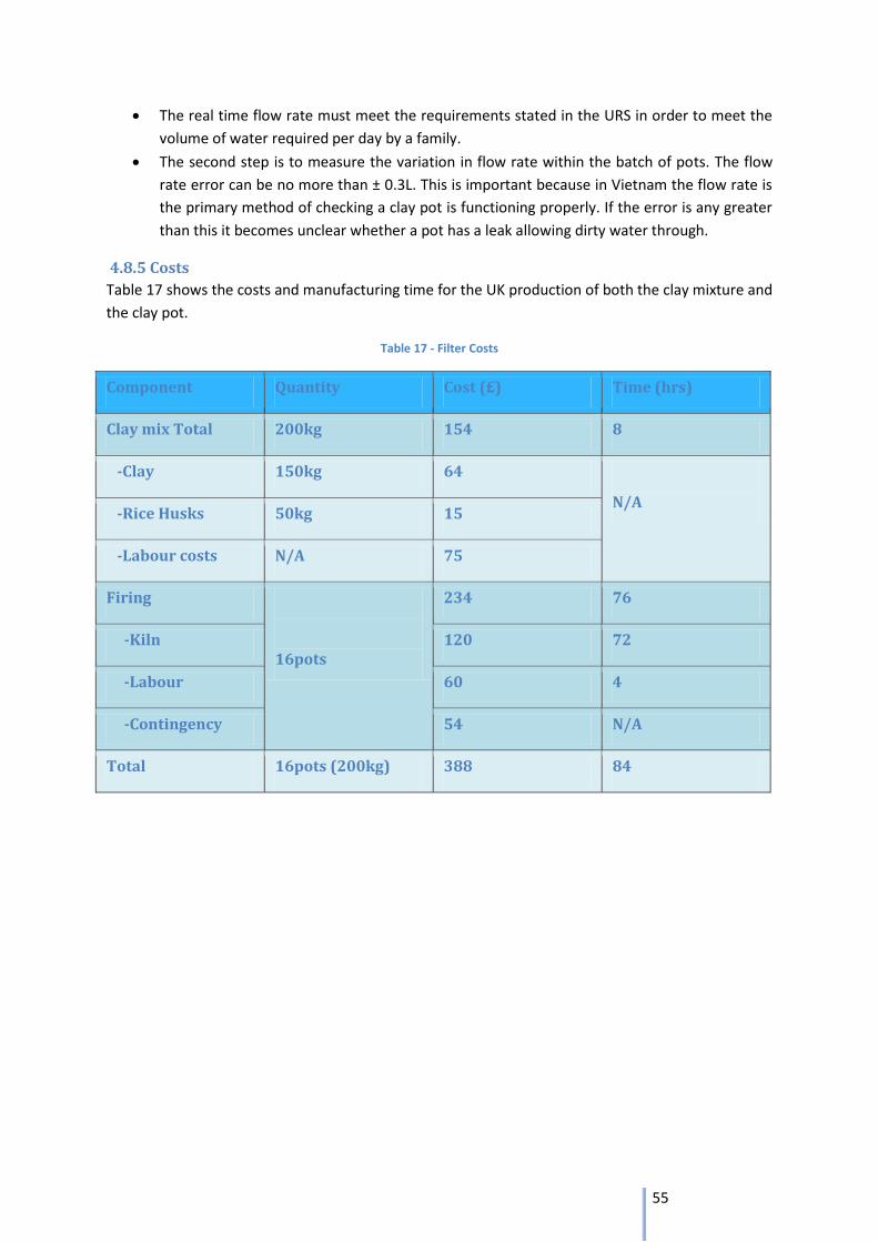
55
The real time flow rate must meet the requirements stated in the URS in order to meet the
volume of water required per day by a family.
The second step is to measure the variation in flow rate within the batch of pots. The flow
rate error can be no more than ± 0.3L. This is important because in Vietnam the flow rate is
the primary method of checking a clay pot is functioning properly. If the error is any greater
than this it becomes unclear whether a pot has a leak allowing dirty water through.
4.8.5 Costs
Table 17 shows the costs and manufacturing time for the UK production of both the clay mixture and
the clay pot.
Table 17 - Filter Costs
Component Quantity Cost (£) Time (hrs)
Clay mix Total 200kg 154 8
-Clay 150kg 64
N/A -Rice Husks 50kg 15
-Labour costs N/A 75
Firing
16pots
234 76
-Kiln 120 72
-Labour 60 4
-Contingency 54 N/A
Total 16pots (200kg) 388 84
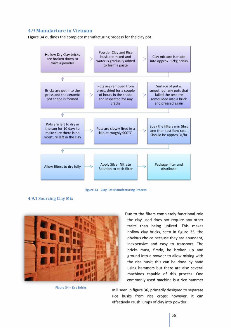
56
4.9 Manufacture in Vietnam Figure 34 outlines the complete manufacturing process for the clay pot.
Figure 33 - Clay Pot Manufacturing Process
4.9.1 Sourcing Clay Mix
Due to the filters completely functional role
the clay used does not require any other
traits than being unfired. This makes
hollow clay bricks, seen in figure 35, the
obvious choice because they are abundant,
inexpensive and easy to transport. The
bricks must, firstly, be broken up and
ground into a powder to allow mixing with
the rice husk; this can be done by hand
using hammers but there are also several
machines capable of this process. One
commonly used machine is a rice hammer
mill seen in figure 36, primarily designed to separate
rice husks from rice crops; however, it can
effectively crush lumps of clay into powder.
Hollow Dry Clay bricks are broken down to
form a powder
Powder Clay and Rice husk are mixed and
water is gradually added to form a paste
Clay mixture is made into approx. 12kg bricks
Bricks are put into the press and the ceramic pot shape is formed
Pots are removed from press, dried for a couple
of hours in the shade and inspected for any
cracks
Surface of pot is smoothed, any pots that
failed the test are remoulded into a brick
and pressed again
Pots are left to dry in the sun for 10 days to make sure there is no
moisture left in the clay
Pots are slowly fired in a kiln at roughly 900°C
Soak the filters min 5hrs and then test flow rate. Should be approx 3L/hr
Allow filters to dry fully Apply Silver Nitrate
Solution to each filter Package filter and
distribute
Figure 34 – Dry Bricks
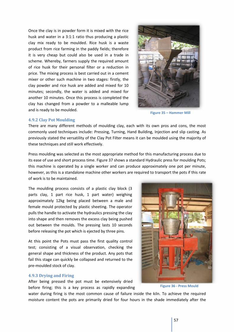
57
Figure 35 – Hammer Mill
Figure 36 - Press Mould
Once the clay is in powder form it is mixed with the rice
husk and water in a 3:1:1 ratio thus producing a plastic
clay mix ready to be moulded. Rice husk is a waste
product from rice farming in the paddy fields; therefore
it is very cheap but could also be used in a trade in
scheme. Whereby, farmers supply the required amount
of rice husk for their personal filter or a reduction in
price. The mixing process is best carried out in a cement
mixer or other such machine in two stages: firstly, the
clay powder and rice husk are added and mixed for 10
minutes; secondly, the water is added and mixed for
another 10 minutes. Once this process is completed the
clay has changed from a powder to a malleable lump
and is ready to be moulded.
4.9.2 Clay Pot Moulding
There are many different methods of moulding clay, each with its own pros and cons, the most
commonly used techniques include: Pressing, Turning, Hand Building, Injection and slip casting. As
previously stated the versatility of the Clay Pot Filter means it can be moulded using the majority of
these techniques and still work effectively.
Press moulding was selected as the most appropriate method for this manufacturing process due to
its ease of use and short process time. Figure 37 shows a standard Hydraulic press for moulding Pots;
this machine is operated by a single worker and can produce approximately one pot per minute,
however, as this is a standalone machine other workers are required to transport the pots if this rate
of work is to be maintained.
The moulding process consists of a plastic clay block (3
parts clay, 1 part rice husk, 1 part water) weighing
approximately 12kg being placed between a male and
female mould protected by plastic sheeting. The operator
pulls the handle to activate the hydraulics pressing the clay
into shape and then removes the excess clay being pushed
out between the moulds. The pressing lasts 10 seconds
before releasing the pot which is ejected by three pins.
At this point the Pots must pass the first quality control
test; consisting of a visual observation, checking the
general shape and thickness of the product. Any pots that
fail this stage can quickly be collapsed and returned to the
pre-moulded stock of clay.
4.9.3 Drying and Firing
After being pressed the pot must be extensively dried
before firing; this is a key process as rapidly expanding
water during firing is the most common cause of failure inside the kiln. To achieve the required
moisture content the pots are primarily dried for four hours in the shade immediately after the
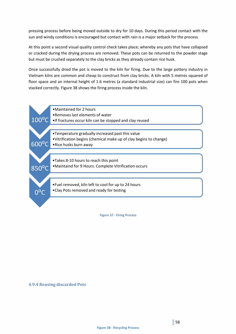
58
pressing process before being moved outside to dry for 10 days. During this period contact with the
sun and windy conditions is encouraged but contact with rain is a major setback for the process.
At this point a second visual quality control check takes place; whereby any pots that have collapsed
or cracked during the drying process are removed. These pots can be returned to the powder stage
but must be crushed separately to the clay bricks as they already contain rice husk.
Once successfully dried the pot is moved to the kiln for firing. Due to the large pottery industry in
Vietnam kilns are common and cheap to construct from clay bricks. A kiln with 5 metres squared of
floor space and an internal height of 1.6 metres (a standard industrial size) can fire 100 pots when
stacked correctly. Figure 38 shows the firing process inside the kiln.
Figure 37 - Firing Process
4.9.4 Reusing discarded Pots
100⁰C
•Maintained for 2 hours
•Removes last elements of water
•If fractures occur kiln can be stopped and clay reused
600⁰C
•Temperature gradually increased past this value
•Vitrification begins (chemical make up of clay begins to change)
•Rice husks burn away
850⁰C •Takes 8-10 hours to reach this point
•Maintaind for 9 Hours. Complete Vitrification occurs
0⁰C •Fuel removed, kiln left to cool for up to 24 hours
•Clay Pots removed and ready for testing
Figure 38 - Recycling Process
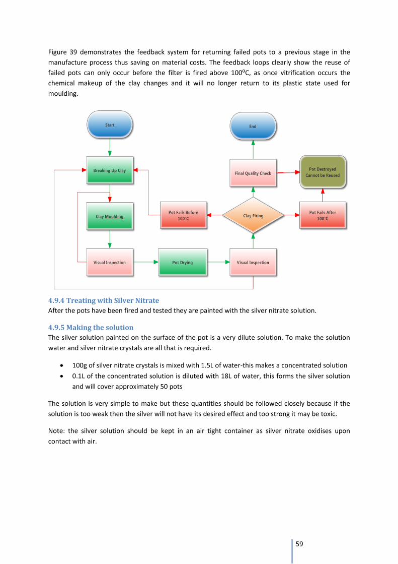
59
Figure 39 demonstrates the feedback system for returning failed pots to a previous stage in the
manufacture process thus saving on material costs. The feedback loops clearly show the reuse of
failed pots can only occur before the filter is fired above 100⁰C, as once vitrification occurs the
chemical makeup of the clay changes and it will no longer return to its plastic state used for
moulding.
4.9.4 Treating with Silver Nitrate
After the pots have been fired and tested they are painted with the silver nitrate solution.
4.9.5 Making the solution
The silver solution painted on the surface of the pot is a very dilute solution. To make the solution
water and silver nitrate crystals are all that is required.
100g of silver nitrate crystals is mixed with 1.5L of water-this makes a concentrated solution
0.1L of the concentrated solution is diluted with 18L of water, this forms the silver solution
and will cover approximately 50 pots
The solution is very simple to make but these quantities should be followed closely because if the
solution is too weak then the silver will not have its desired effect and too strong it may be toxic.
Note: the silver solution should be kept in an air tight container as silver nitrate oxidises upon
contact with air.
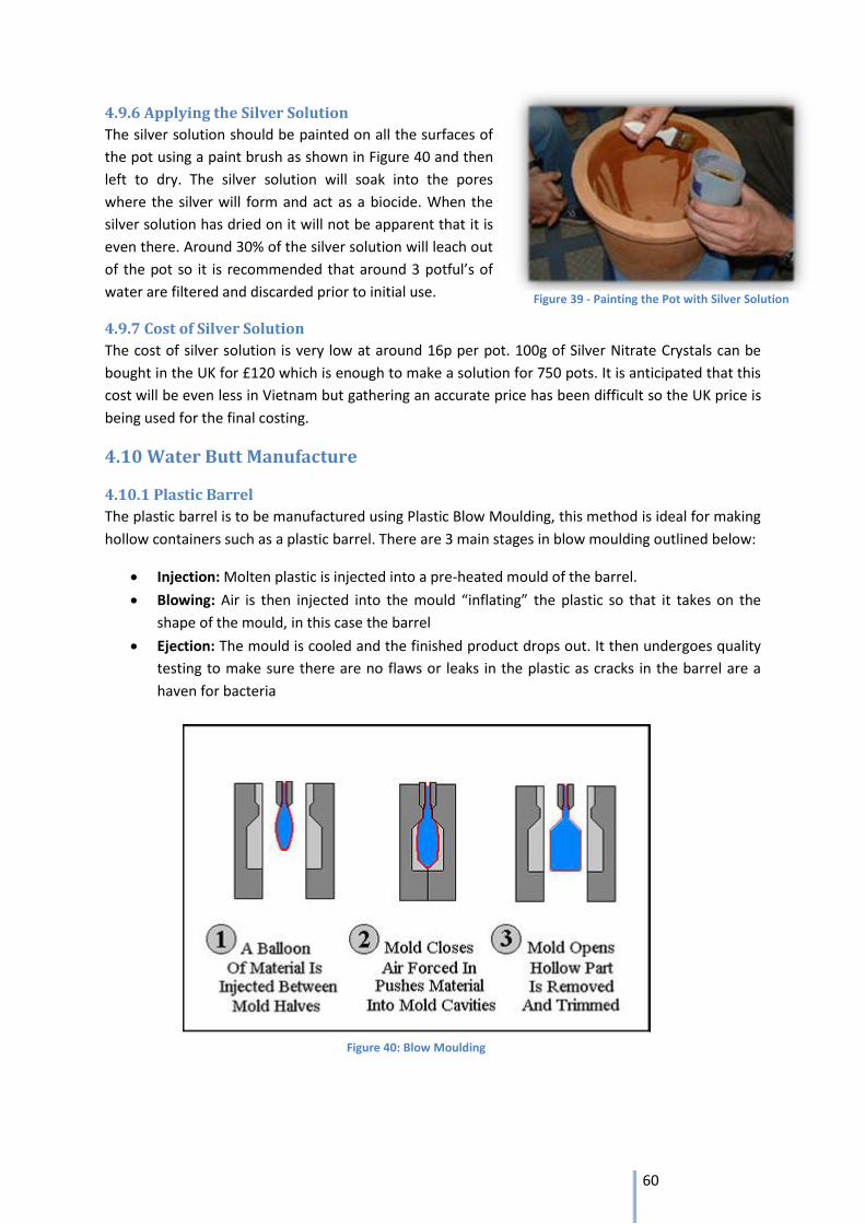
60
4.9.6 Applying the Silver Solution
The silver solution should be painted on all the surfaces of
the pot using a paint brush as shown in Figure 40 and then
left to dry. The silver solution will soak into the pores
where the silver will form and act as a biocide. When the
silver solution has dried on it will not be apparent that it is
even there. Around 30% of the silver solution will leach out
of the pot so it is recommended that around 3 potful’s of
water are filtered and discarded prior to initial use.
4.9.7 Cost of Silver Solution
The cost of silver solution is very low at around 16p per pot. 100g of Silver Nitrate Crystals can be
bought in the UK for £120 which is enough to make a solution for 750 pots. It is anticipated that this
cost will be even less in Vietnam but gathering an accurate price has been difficult so the UK price is
being used for the final costing.
4.10 Water Butt Manufacture
4.10.1 Plastic Barrel
The plastic barrel is to be manufactured using Plastic Blow Moulding, this method is ideal for making
hollow containers such as a plastic barrel. There are 3 main stages in blow moulding outlined below:
Injection: Molten plastic is injected into a pre-heated mould of the barrel.
Blowing: Air is then injected into the mould “inflating” the plastic so that it takes on the
shape of the mould, in this case the barrel
Ejection: The mould is cooled and the finished product drops out. It then undergoes quality
testing to make sure there are no flaws or leaks in the plastic as cracks in the barrel are a
haven for bacteria
Figure 40: Blow Moulding
Figure 39 - Painting the Pot with Silver Solution
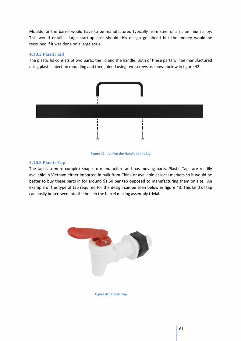
61
Moulds for the barrel would have to be manufactured typically from steel or an aluminium alloy.
This would entail a large start-up cost should this design go ahead but the money would be
recouped if it was done on a large scale.
4.10.2 Plastic Lid
The plastic lid consists of two parts; the lid and the handle. Both of these parts will be manufactured
using plastic injection moulding and then joined using two screws as shown below in figure 42.
Figure 41 - Joining the Handle to the Lid
4.10.3 Plastic Tap
The tap is a more complex shape to manufacture and has moving parts. Plastic Taps are readily
available in Vietnam either imported in bulk from China or available at local markets so it would be
better to buy these parts in for around $1.50 per tap opposed to manufacturing them on site. An
example of the type of tap required for the design can be seen below in figure 43. This kind of tap
can easily be screwed into the hole in the barrel making assembly trivial.
Figure 42: Plastic Tap
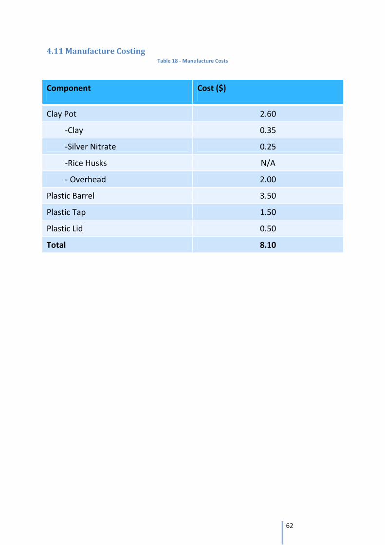
62
4.11 Manufacture Costing Table 18 - Manufacture Costs
Component Cost ($)
Clay Pot 2.60
-Clay 0.35
-Silver Nitrate 0.25
-Rice Husks N/A
- Overhead 2.00
Plastic Barrel 3.50
Plastic Tap 1.50
Plastic Lid 0.50
Total 8.10
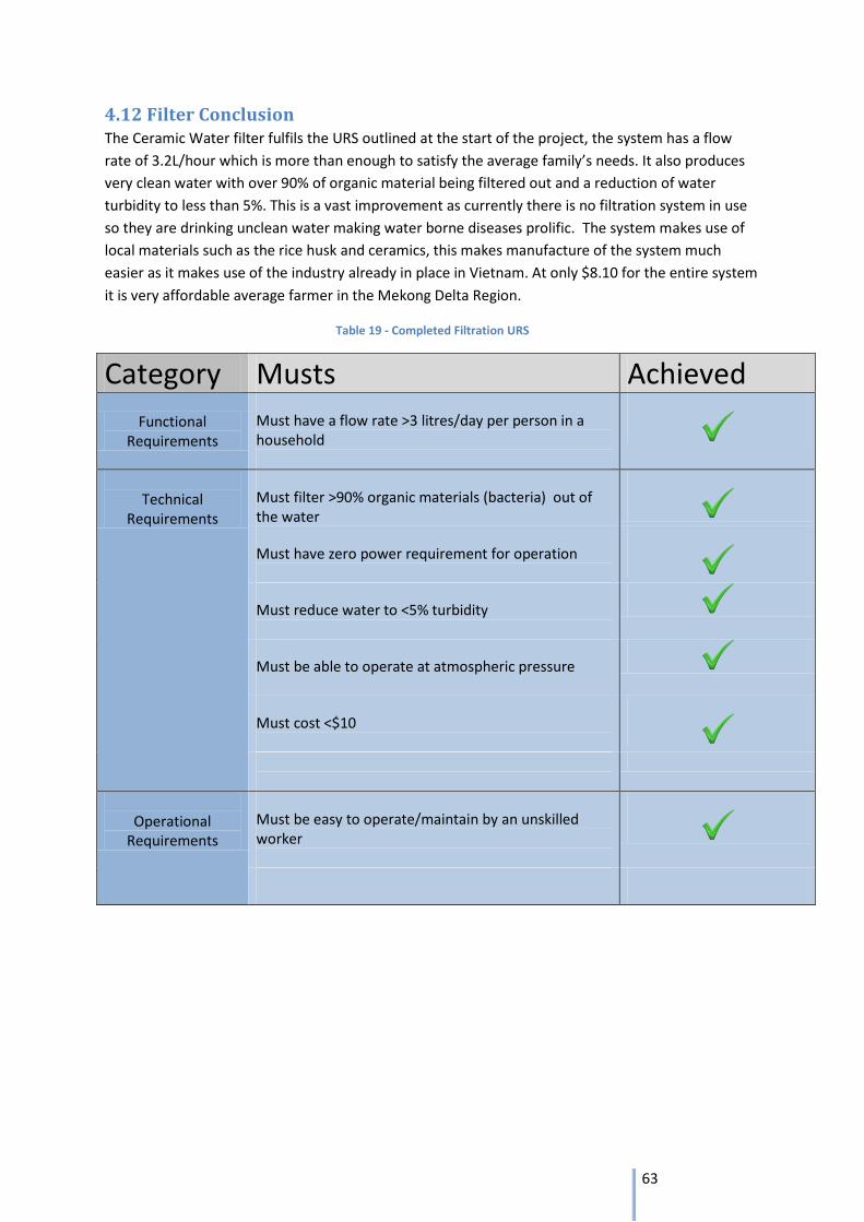
63
4.12 Filter Conclusion The Ceramic Water filter fulfils the URS outlined at the start of the project, the system has a flow
rate of 3.2L/hour which is more than enough to satisfy the average family’s needs. It also produces
very clean water with over 90% of organic material being filtered out and a reduction of water
turbidity to less than 5%. This is a vast improvement as currently there is no filtration system in use
so they are drinking unclean water making water borne diseases prolific. The system makes use of
local materials such as the rice husk and ceramics, this makes manufacture of the system much
easier as it makes use of the industry already in place in Vietnam. At only $8.10 for the entire system
it is very affordable average farmer in the Mekong Delta Region.
Table 19 - Completed Filtration URS
Category Musts Achieved
Functional Requirements
Must have a flow rate >3 litres/day per person in a household
Technical
Requirements
Must filter >90% organic materials (bacteria) out of the water
Must have zero power requirement for operation
Must reduce water to <5% turbidity
Must be able to operate at atmospheric pressure
Must cost <$10
Operational
Requirements
Must be easy to operate/maintain by an unskilled worker
64
5 Discussion
5.1 Adaptability of the integrated system
The greatest issue with a domestic design approach is accounting for the inevitable differences in
the layout of each household within the Mekong Delta. Although the storage methods of each family
are similar in principle, it is the implementation of these methods that differ because it has been
adapted to the housing styles of each family. The purpose of separating the key aspects of this
project was to continue this adaptability to the dimensions of any household. The guidelines for the
guttering system allow the rainwater to be collected from any roof shape to the storage unit itself.
The ferrocement water tank, though permanent once built, can be located where ever the family
wishes it to be and has the potential to be connected to the household via water piping. The
filtration unit has been designed to be portable and unobtrusive within the home itself. Effort is
inevitably required to transfer water from the storage unit to the filter but to design a fully
automated system that would perform this task will not only increase expenditure but restrict
adaptability. Such a system would involve mechanical parts that, in order to function, are highly
dependent on specific locations.
5.2 Improvements on current methods
The improvements that this integrated design provides will be invaluable compared to the current
water storage and drinking habits in the Mekong Delta. Each section of the project will have a
positive effect on the livelihoods of families in the region. Although the guttering system may not
differ vastly in principle from the current adopted guttering methods, it does have the added feature
of allowing heavily contaminated water from the roofs to be siphoned off. The ferrocement tank has
condensed what would currently be four separate ceramic jars into one storage unit whilst still
providing sufficient amounts of drinking and cooking water during a six month dry season. Whereas
the filtration unit will provide an opportunity for cleaner water that many households have never
had.
Despite the marked improvements that this system will have, the cultural integrity of Vietnamese
people will still remain undisturbed. The culture of the region would dictate that the construction of
the storage facility would be performed by a male. However, the same cultural dictation would also
apply to moving and installing the extremely heavy ceramic jars. Furthermore the ease of
maintenance of the ferrocement tank allows both genders to perform this task. This complies, yet
again, with the cultural view that general housekeeping is done by both male and females.
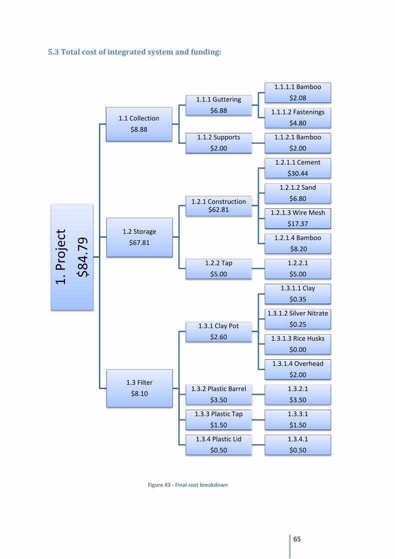
65
1. P
roje
ct
$8
4.7
9
1.1 Collection
$8.88
1.1.1 Guttering
$6.88
1.1.1.1 Bamboo
$2.08
1.1.1.2 Fastenings
$4.80
1.1.2 Supports
$2.00
1.1.2.1 Bamboo
$2.00
1.2 Storage
$67.81
1.2.1 Construction $62.81
1.2.1.1 Cement
$30.44
1.2.1.2 Sand
$6.80
1.2.1.3 Wire Mesh
$17.37
1.2.1.4 Bamboo
$8.20
1.2.2 Tap
$5.00
1.2.2.1
$5.00
1.3 Filter
$8.10
1.3.1 Clay Pot
$2.60
1.3.1.1 Clay
$0.35
1.3.1.2 Silver Nitrate
$0.25
1.3.1.3 Rice Husks
$0.00
1.3.1.4 Overhead
$2.00
1.3.2 Plastic Barrel
$3.50
1.3.2.1
$3.50
1.3.3 Plastic Tap
$1.50
1.3.3.1
$1.50
1.3.4 Plastic Lid
$0.50
1.3.4.1
$0.50
Figure 43 - Final cost breakdown
5.3 Total cost of integrated system and funding:
66
The previous table illustrates the costs of the entire integrated system. The ambiguity of the
collection system is due to the unknown dimensions of households. The price of this system will
inevitably vary according to the size of the home in question. The projected total cost comes to little
over $80, however, this value is based on the assumption that every system is constructed and
installed by an unpaid labourer or volunteer.
The project at hand is an Engineers Without Borders (EWB) project, so it is in its nature to be cost-
effective and funded by charities, humanitarian projects or affordable for the users. The final cost of
the design came out to be less than their current option, for which they receive no funding, so the
design can already be implemented without any external resourcing. However, as this is part of a
humanitarian project the initial funding should come from EWB. EWB can provide funding and
volunteers to go out and aid with the construction and finance of the project.
5.4 Worst Case Scenarios and Contingency Plans
5.4.1Flooding
The main contingency with which the system has had to be designed to consider is flooding. With
flood levels now reaching as high as four metres[20] due to global warming, both large walls of water
and floating debris are expected to be a major issue.
A four metre flood of course, is not the norm, merely an extreme. Water that deep will have fully
enveloped the house and the water system is unlikely to be the major concern. The filter is portable
so can be taken with the user to any temporary accommodation but the tank and guttering will have
to be left to the elements with the house.
In smaller scaled floods however, the system should cope relatively well. The tank has been designed
so that it is strong and rigid with a factor of safety three times as large as the 10 needed for a water
tank. Floating debris such as uprooted trees may crash into walls cracking them, and if the flood
waters rise above the top of the tank contaminated water can pour in, but neither of these problems
are without a solution. The ferrocement used to build the tank, is as easy to repair as it is to
construct, with small amounts of cement pasted into the cracks filling them. As for the contaminated
water, the washout valve is there to remove it. The guttering is less durable, but as it is so cheap (or
the bamboo can be harvested locally for free) and simple, it can merely be replaced where required
and as stated before, the filter is portable so should avoid any flood.
5.4.2 Typhoons
Near to the coast, typhoons are relatively common in Vietnam. Severe typhoons hit about once
every 5 years on average21. These tropical storms bring strong winds from the oceans causing further
flooding and gale force winds. Flooding, as discussed, should not be a major concern and neither,
should the winds.
The circular nature of the tank should help somewhat in dealing with the strong winds as
aerodynamically, with no flat faces, the wind should pass by easily, and the strong foundations and
large weight will prevent the tank blowing away.
20
http://www.ifrc.org/en/news-and-media/news-stories/asia-pacific/vietnam/emerging-crisis-in-viet-nam-as-mekong-delta-reaches-record-levels/ - last accessed 3/3/13 21
http://www.holiday-weather.com/country/vietnam/ - last accessed 3/3/13
67
The guttering is attached to both supports on the roof and struts planted in the ground. This is not as
secure as the tank and the lightweight bamboo poles are liable to blow away. However, as
mentioned, these are cheap/free to replace. The filter, again, will be kept safe inside.
6 Conclusion
The design mission was to design and provide a water collection, storage and filtration system that is
both affordable and effective for a household in the Mekong Delta.
By comparing the proposed integrated design to this mission statement it is clear that the objective
of this project has been successfully completed. The collection system has been designed to harvest
the required rainwater and has been adapted to their current method whilst also including an initial
filtration.
The water then flows into the storage that will contain it throughout the dry season, protecting it
from the sunlight and other bacteria culture factors. This is all in a ferrocement tank that costs less
than their current option and can be built by an unskilled labourer. When necessary the water can
then be extracted at more than the minimum flow rate given by the International SPHERE Standards.
After extraction, the water is then carried to the in house filtration system where it is filtered a
second, more thorough, time. This is done at atmospheric pressure and at three litres per hour;
again this is faster than the minimum SPHERE standard requirement. This easily replaceable filter is
also cost-effective at less than $10.
The proposed integrated system is more affordable than the current option, cleaner than the
current option, provides sufficient amount of water and is adjustable to user parameters. The design
has successfully fulfilled every user requirement specification and is therefore the optimum
rainwater storage and filtration solution available to the people of the Mekong Delta.
68
7 References United Nations High Commissioner for Refugees, ‘Large Ferro-Cement Water Tank, Design
Parameters and Construction Details’, July 2006.
Sakthivel, P.B., Jagannathan, A. ‘Ferrocement Construction Technology and its Applications – A
Review’, 2010.
American Concrete Institute (ACI) Committee 549, ‘State-of-the-art Report on Ferrocement’, January
24 1997, pp. 3 -15.
Brian Skinner, Bob Reed and Rod Shaw, ‘Ferrocement Water Tanks’, Loughborough University.
Chindaprasirt, P., et al. A Study and Development of Low-Cost Rainwater Tanks, Khon Kaen
University, Bangkok, 1986.
Nissen-Petersen, K., How to Build Smaller Water Tanks and Jars, ASAC Consultants Ltd., Kitui, Kenya,
1992.
Francis E. Brink and Paul J. Rush ‘BAMBOO REINFORCED CONCRETE CONSTRUCTION’, Port Hueneme,
California, February 1966.
‘http://diydata.com/general_building/concrete/concrete_mixing.php’ (last accessed 25/02/2013)
‘http://www.ewb.org.au/discussions/1273/11437’ (last accessed (5/03/2013)
Disenbacher, A. L. and Brauer, F. E., “Material Development Design, Construction and Evaluation of
Ferrocement Planning Boat,” Marine Technology & S., V. 11, No. 3, July 1984, pp. 277-296.
http://www.potterswithoutborders.com/ (last accessed (2/03/2013)
http://wateradvocate.org/potters.htm (last accessed (23/02/2013)
http://www.rdic.org/ (last accessed (5/03/2013)
http://www.amazon.co.uk/ (last accessed (5/03/2013)
http://www.bamboocraft.net/forums/showthread.php?t=382 (last accessed (5/03/2013)
http://www.ehow.com/how_8490856_split-bamboo-poles.html#ixzz2Ii8WAQXP(lastaccessed
(5/03/2013)
http://www.guaduabamboo.com/how-to-split-bamboo.html#ixzz2Ii9ZXReL(lastaccessed (5/03/2013)
http://www.milmour.com/milmour/blow_molding_images.asp (last accessed (3/03/2013)
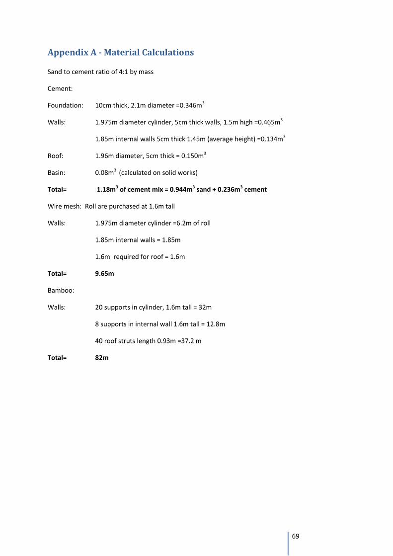
69
Appendix A - Material Calculations
Sand to cement ratio of 4:1 by mass
Cement:
Foundation: 10cm thick, 2.1m diameter =0.346m3
Walls: 1.975m diameter cylinder, 5cm thick walls, 1.5m high =0.465m3
1.85m internal walls 5cm thick 1.45m (average height) =0.134m3
Roof: 1.96m diameter, 5cm thick = 0.150m3
Basin: 0.08m3 (calculated on solid works)
Total= 1.18m3 of cement mix = 0.944m3 sand + 0.236m3 cement
Wire mesh: Roll are purchased at 1.6m tall
Walls: 1.975m diameter cylinder =6.2m of roll
1.85m internal walls = 1.85m
1.6m required for roof = 1.6m
Total= 9.65m
Bamboo:
Walls: 20 supports in cylinder, 1.6m tall = 32m
8 supports in internal wall 1.6m tall = 12.8m
40 roof struts length 0.93m =37.2 m
Total= 82m
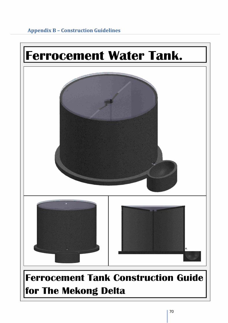
70
Appendix B – Construction Guidelines
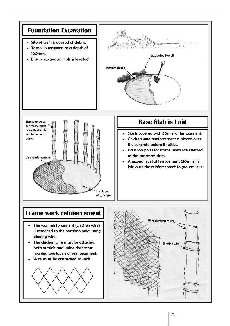
71
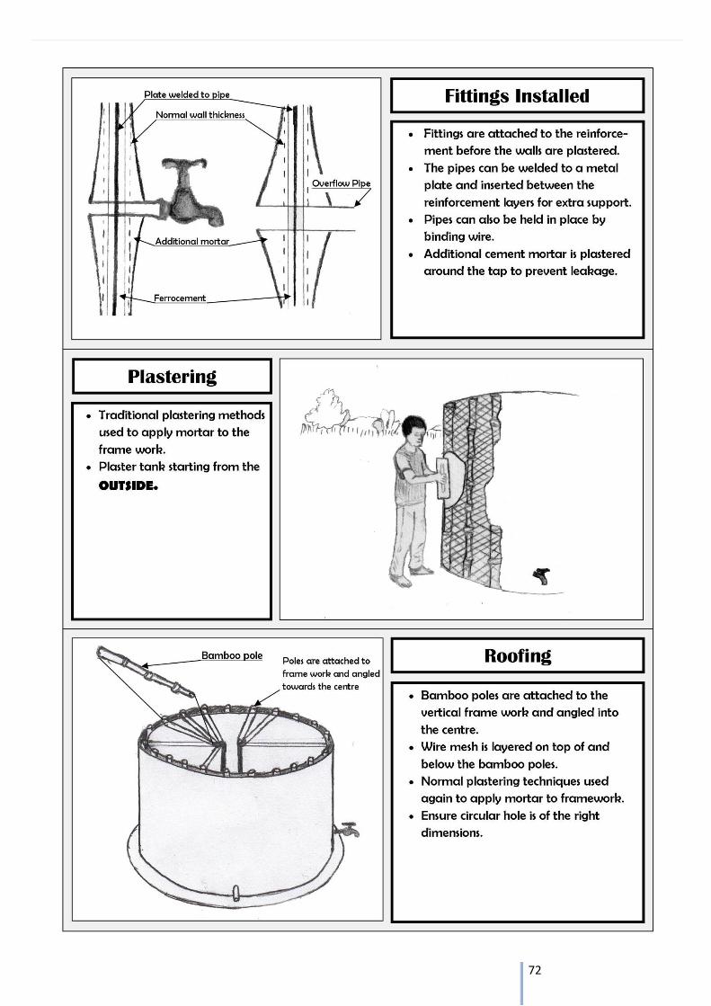
72
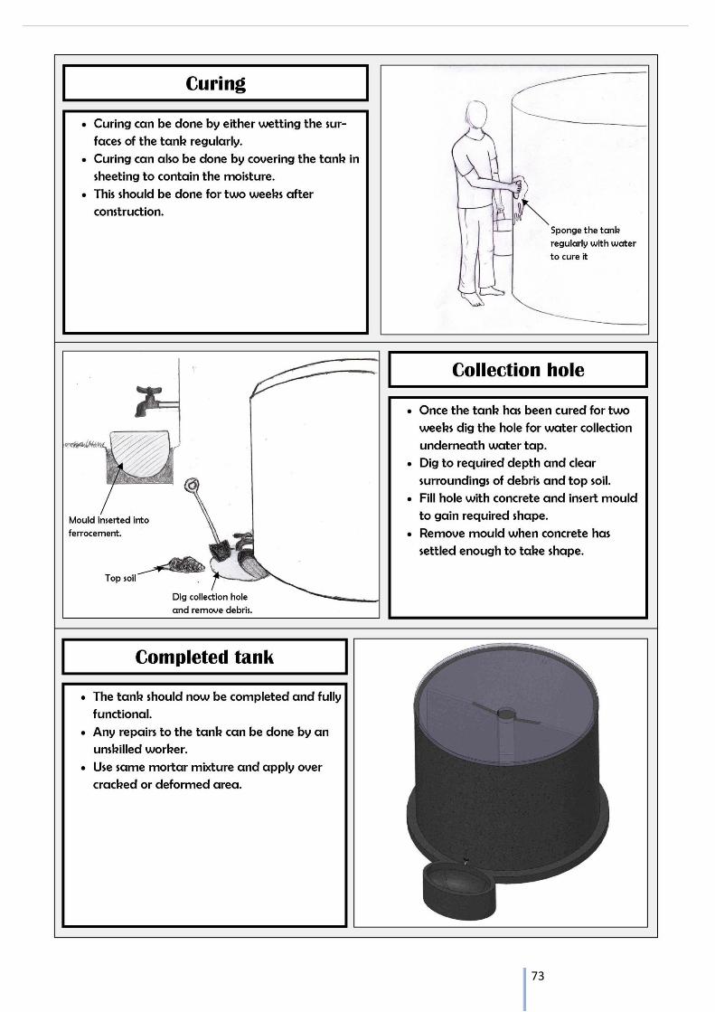
73
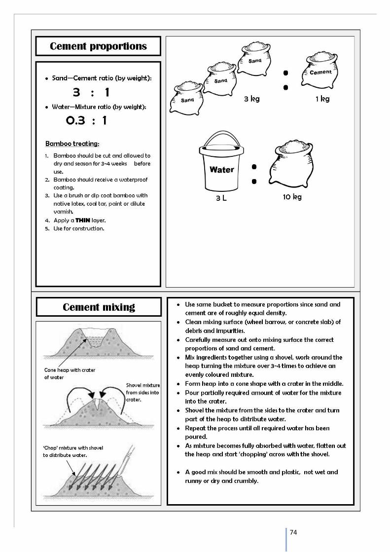
74
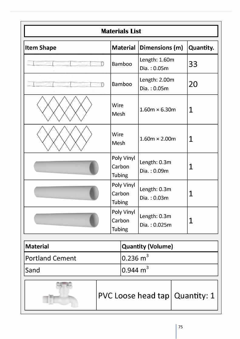
75
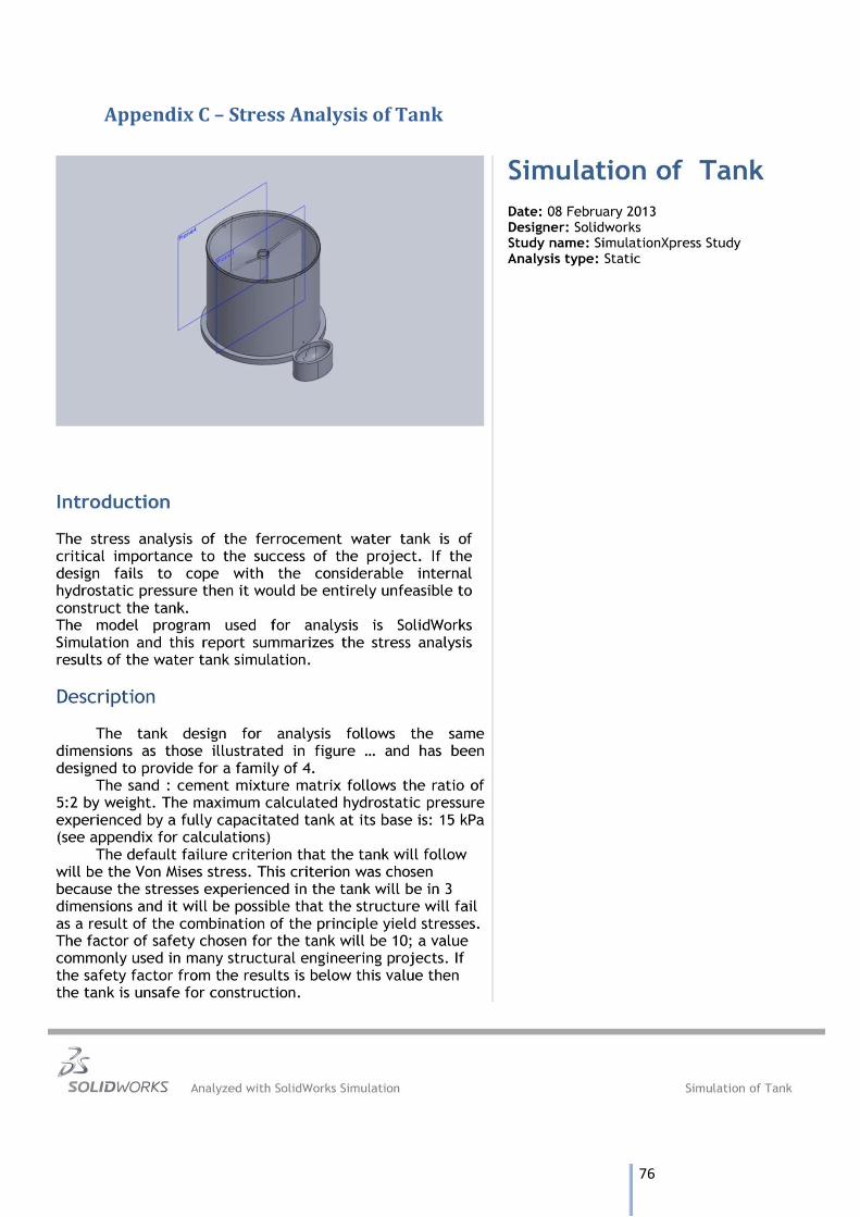
76
Appendix C – Stress Analysis of Tank
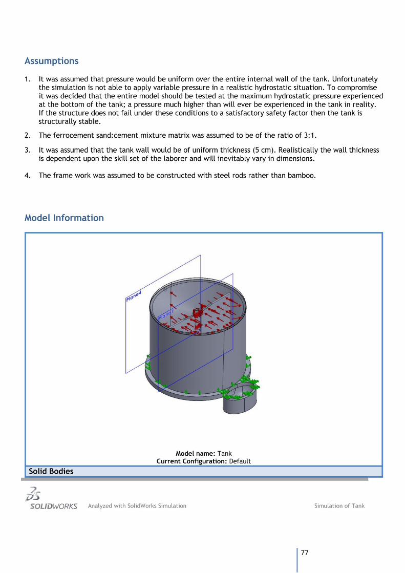
77
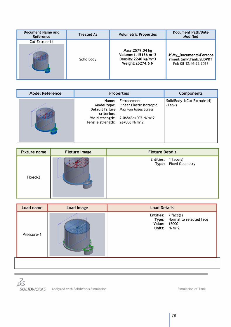
78
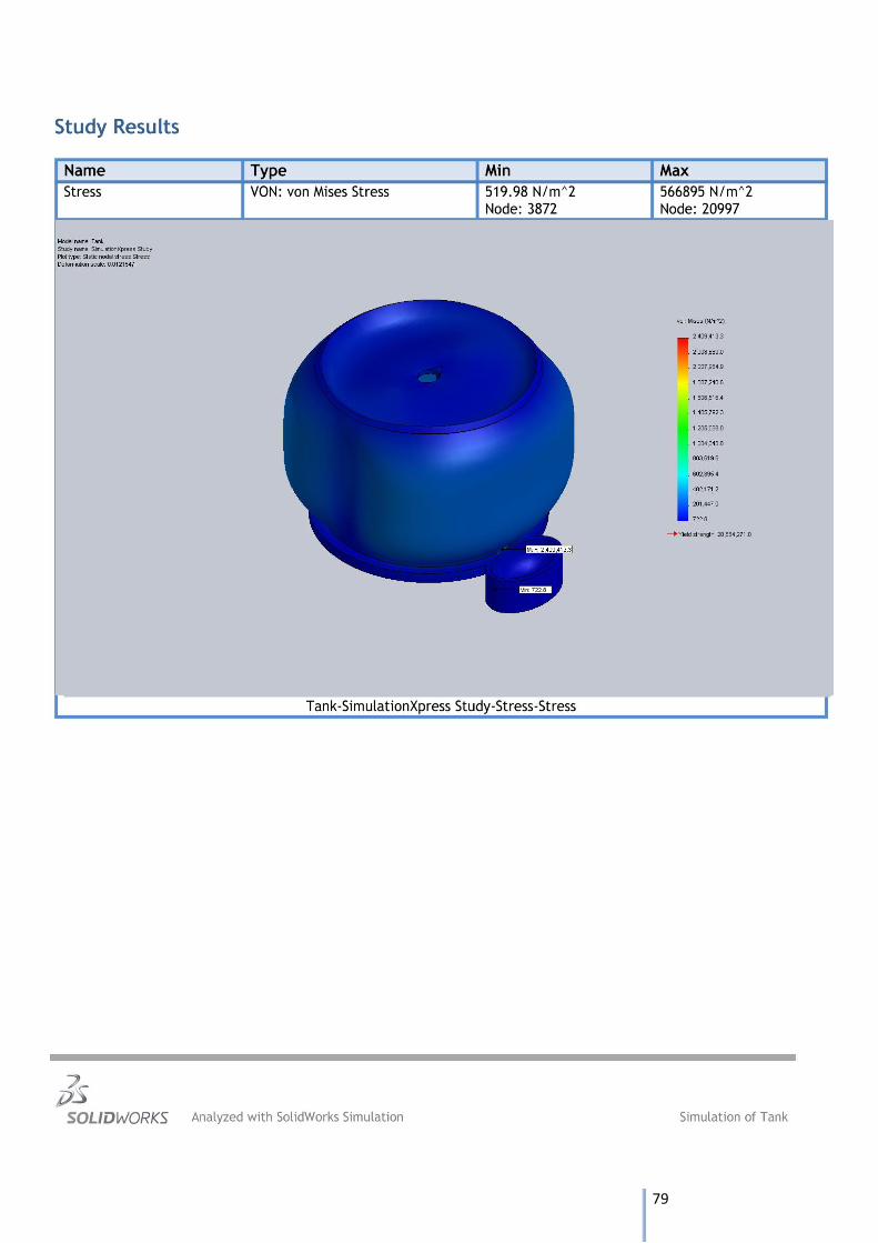
79
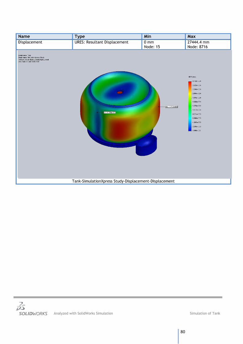
80
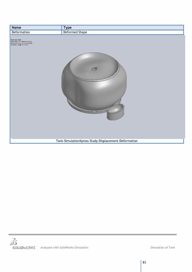
81
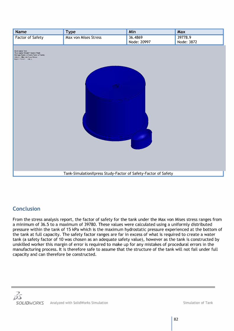
82

83
Appendix D – CAD Drawings
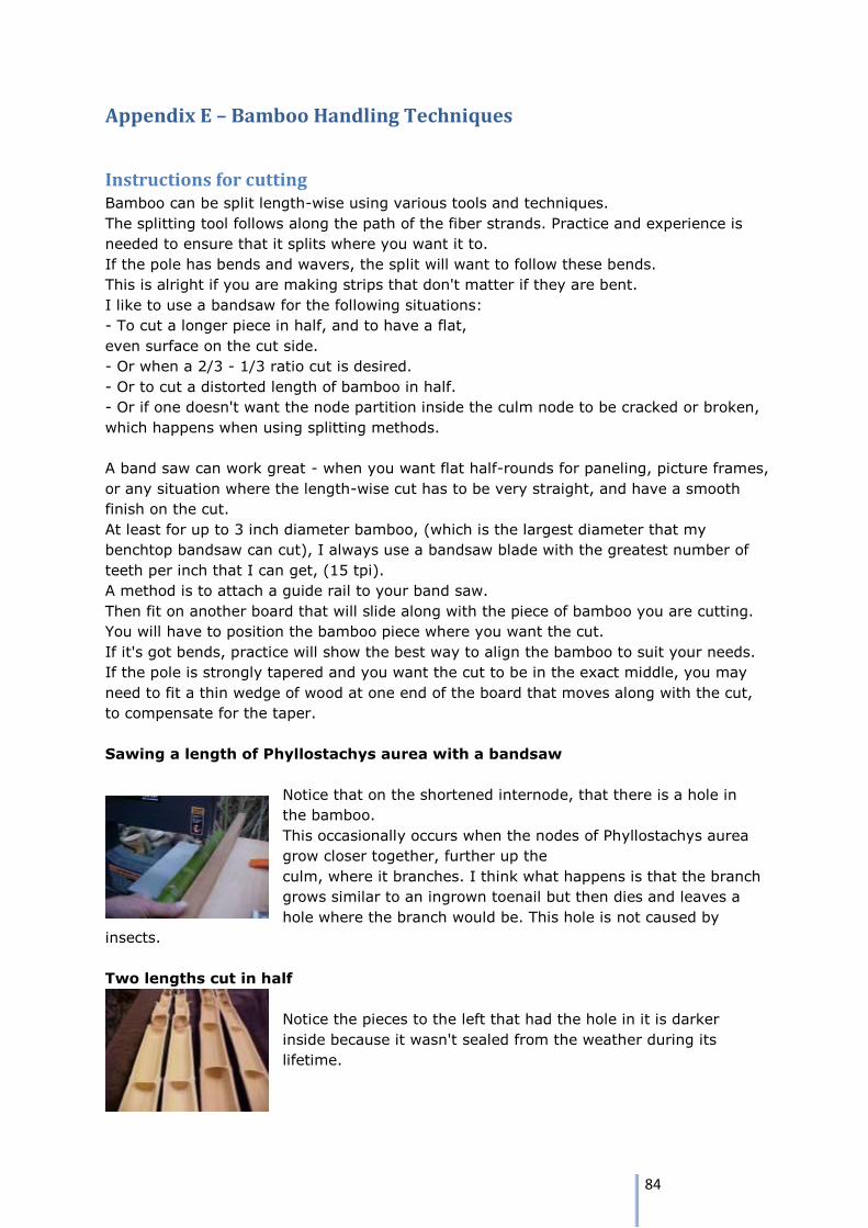
84
Appendix E – Bamboo Handling Techniques
Instructions for cutting Bamboo can be split length-wise using various tools and techniques.
The splitting tool follows along the path of the fiber strands. Practice and experience is
needed to ensure that it splits where you want it to.
If the pole has bends and wavers, the split will want to follow these bends.
This is alright if you are making strips that don't matter if they are bent.
I like to use a bandsaw for the following situations:
- To cut a longer piece in half, and to have a flat,
even surface on the cut side.
- Or when a 2/3 - 1/3 ratio cut is desired.
- Or to cut a distorted length of bamboo in half.
- Or if one doesn't want the node partition inside the culm node to be cracked or broken,
which happens when using splitting methods.
A band saw can work great - when you want flat half-rounds for paneling, picture frames,
or any situation where the length-wise cut has to be very straight, and have a smooth
finish on the cut.
At least for up to 3 inch diameter bamboo, (which is the largest diameter that my
benchtop bandsaw can cut), I always use a bandsaw blade with the greatest number of
teeth per inch that I can get, (15 tpi).
A method is to attach a guide rail to your band saw.
Then fit on another board that will slide along with the piece of bamboo you are cutting.
You will have to position the bamboo piece where you want the cut.
If it's got bends, practice will show the best way to align the bamboo to suit your needs.
If the pole is strongly tapered and you want the cut to be in the exact middle, you may
need to fit a thin wedge of wood at one end of the board that moves along with the cut,
to compensate for the taper.
Sawing a length of Phyllostachys aurea with a bandsaw
Notice that on the shortened internode, that there is a hole in
the bamboo.
This occasionally occurs when the nodes of Phyllostachys aurea
grow closer together, further up the
culm, where it branches. I think what happens is that the branch
grows similar to an ingrown toenail but then dies and leaves a
hole where the branch would be. This hole is not caused by
insects.
Two lengths cut in half
Notice the pieces to the left that had the hole in it is darker
inside because it wasn't sealed from the weather during its
lifetime.
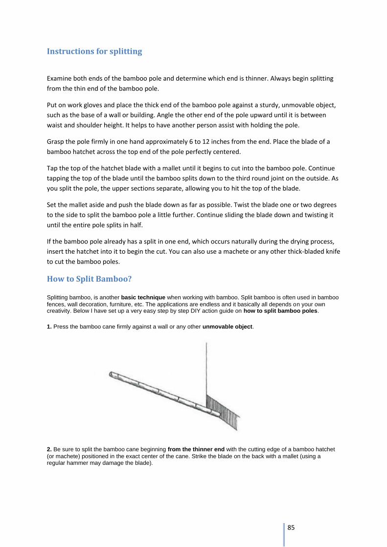
85
Instructions for splitting
Examine both ends of the bamboo pole and determine which end is thinner. Always begin splitting
from the thin end of the bamboo pole.
Put on work gloves and place the thick end of the bamboo pole against a sturdy, unmovable object,
such as the base of a wall or building. Angle the other end of the pole upward until it is between
waist and shoulder height. It helps to have another person assist with holding the pole.
Grasp the pole firmly in one hand approximately 6 to 12 inches from the end. Place the blade of a
bamboo hatchet across the top end of the pole perfectly centered.
Tap the top of the hatchet blade with a mallet until it begins to cut into the bamboo pole. Continue
tapping the top of the blade until the bamboo splits down to the third round joint on the outside. As
you split the pole, the upper sections separate, allowing you to hit the top of the blade.
Set the mallet aside and push the blade down as far as possible. Twist the blade one or two degrees
to the side to split the bamboo pole a little further. Continue sliding the blade down and twisting it
until the entire pole splits in half.
If the bamboo pole already has a split in one end, which occurs naturally during the drying process,
insert the hatchet into it to begin the cut. You can also use a machete or any other thick-bladed knife
to cut the bamboo poles.
How to Split Bamboo?
Splitting bamboo, is another basic technique when working with bamboo. Split bamboo is often used in bamboo
fences, wall decoration, furniture, etc. The applications are endless and it basically all depends on your own creativity. Below I have set up a very easy step by step DIY action guide on how to split bamboo poles.
1. Press the bamboo cane firmly against a wall or any other unmovable object.
2. Be sure to split the bamboo cane beginning from the thinner end with the cutting edge of a bamboo hatchet
(or machete) positioned in the exact center of the cane. Strike the blade on the back with a mallet (using a regular hammer may damage the blade).
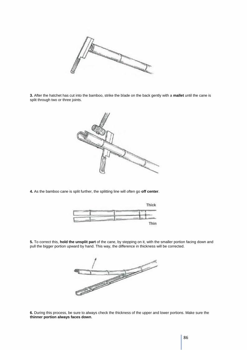
86
3. After the hatchet has cut into the bamboo, strike the blade on the back gently with a mallet until the cane is
split through two or three joints.
4. As the bamboo cane is split further, the splitting line will often go off center.
5. To correct this, hold the unsplit part of the cane, by stepping on it, with the smaller portion facing down and
pull the bigger portion upward by hand. This way, the difference in thickness will be corrected.
6. During this process, be sure to always check the thickness of the upper and lower portions. Make sure the thinner portion always faces down.
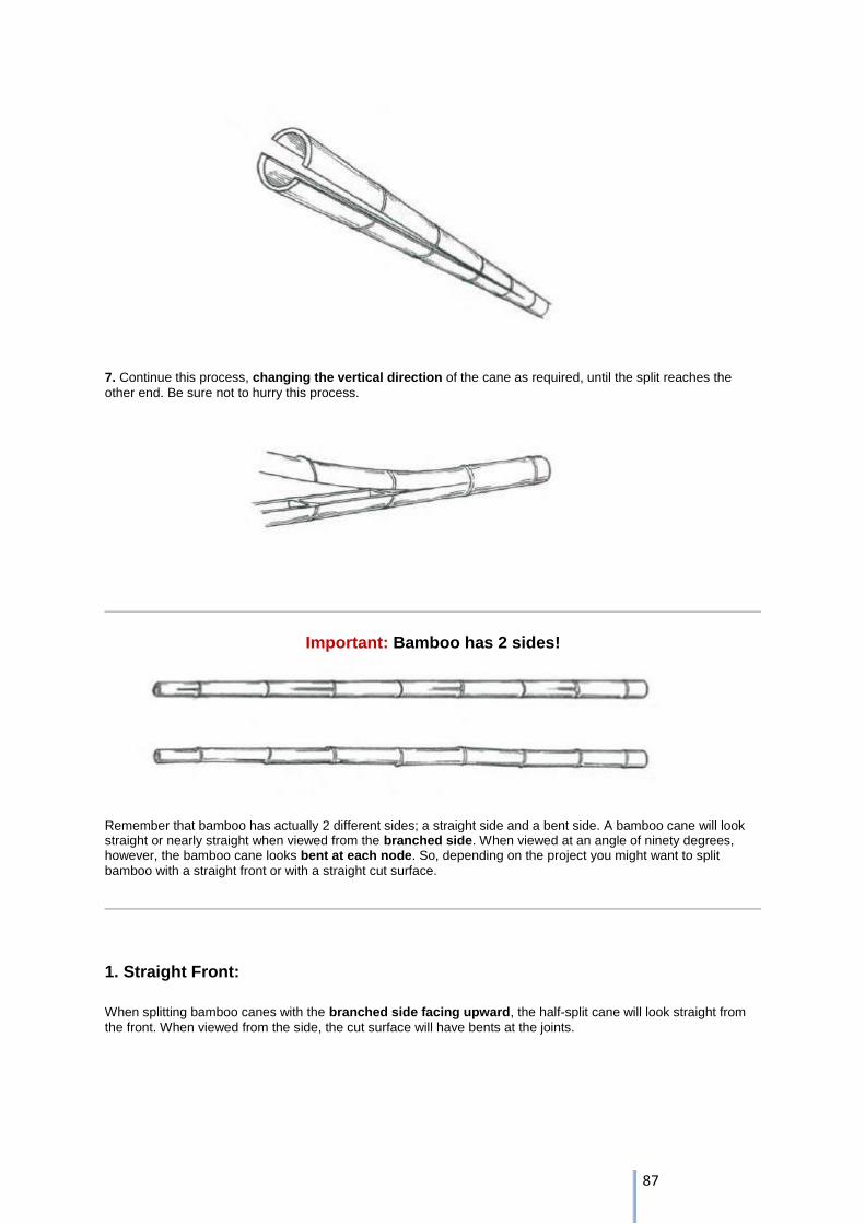
87
7. Continue this process, changing the vertical direction of the cane as required, until the split reaches the
other end. Be sure not to hurry this process.
Important: Bamboo has 2 sides!
Remember that bamboo has actually 2 different sides; a straight side and a bent side. A bamboo cane will look straight or nearly straight when viewed from the branched side. When viewed at an angle of ninety degrees, however, the bamboo cane looks bent at each node. So, depending on the project you might want to split bamboo with a straight front or with a straight cut surface.
1. Straight Front:
When splitting bamboo canes with the branched side facing upward, the half-split cane will look straight from
the front. When viewed from the side, the cut surface will have bents at the joints.
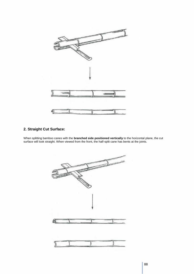
88
2. Straight Cut Surface:
When splitting bamboo canes with the branched side positioned vertically to the horizontal plane, the cut
surface will look straight. When viewed from the front, the half-split cane has bents at the joints.
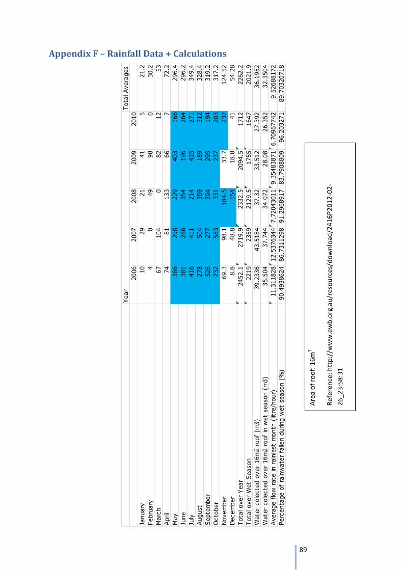
89
Appendix F – Rainfall Data + Calculations
Tota
l Avera
ges
2006
2007
2008
2009
2010
January
10
29
21
41
521.2
Febru
ary
40
49
98
030.2
Marc
h67
104
082
12
53
April
74
81
133
66
772.2
May
386
298
229
403
166
296.4
June
381
286
354
196
264
296.2
July
416
411
214
435
271
349.4
August
278
504
359
189
312
328.4
Septe
mber
526
277
304
295
194
319.2
Octo
ber
232
583
331
237
203
317.2
Novem
ber
69.3
98.1
184.5
33.7
237
124.5
2
Decem
ber
8.8
48.8
154
18.8
41
54.2
8
Tota
l over
Year
2452.1
2719.9
2332.5
2094.5
1712
2262.2
Tota
l over
Wet
Season
2219
2359
2129.5
1755
1647
2021.9
Wate
r cole
cte
d o
ver
16m
2 r
oof
(m3)
39.2
336
43.5
184
37.3
233.5
12
27.3
92
36.1
952
Wate
r cole
cte
d o
ver
16m
2 r
oof
in w
et
season (
m3)
35.5
04
37.7
44
34.0
72
28.0
826.3
52
32.3
504
Avera
ge f
low
rate
in r
ain
iest
month
(lit
re/h
our)
11.3
11828
12.5
376344
7.7
2043011
9.3
5483871
6.7
0967742
9.5
2688172
Perc
enta
ge o
f ra
inw
ate
r fa
llen d
uring w
et
season (
%)
90.4
938624
86.7
311298
91.2
968917
83.7
908809
96.2
03271
89.7
0320718
Year
Are
a o
f ro
of:
16m
3
Ref
ere
nce
: htt
p:/
/ww
w.e
wb
.org
.au
/res
ou
rces
/do
wn
load
/24
16P
20
12
-02
-
26
_23:
58:3
1
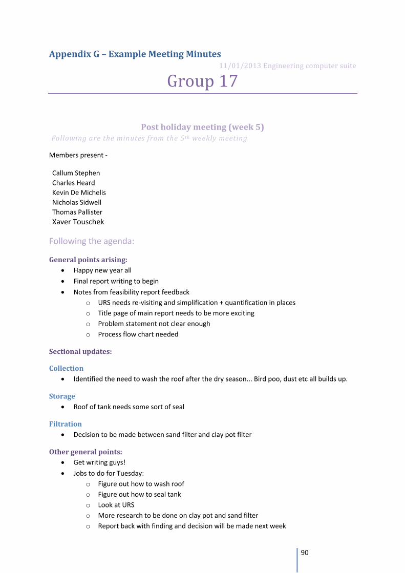
90
Appendix G – Example Meeting Minutes 11/01/2013 Engineering computer suite
Group 17
Post holiday meeting (week 5) Following are the minutes from the 5 th weekly meeting
Members present -
Callum Stephen
Charles Heard
Kevin De Michelis
Nicholas Sidwell
Thomas Pallister
Xaver Touschek
Following the agenda:
General points arising:
Happy new year all
Final report writing to begin
Notes from feasibility report feedback
o URS needs re-visiting and simplification + quantification in places
o Title page of main report needs to be more exciting
o Problem statement not clear enough
o Process flow chart needed
Sectional updates:
Collection
Identified the need to wash the roof after the dry season... Bird poo, dust etc all builds up.
Storage
Roof of tank needs some sort of seal
Filtration
Decision to be made between sand filter and clay pot filter
Other general points:
Get writing guys!
Jobs to do for Tuesday:
o Figure out how to wash roof
o Figure out how to seal tank
o Look at URS
o More research to be done on clay pot and sand filter
o Report back with finding and decision will be made next week
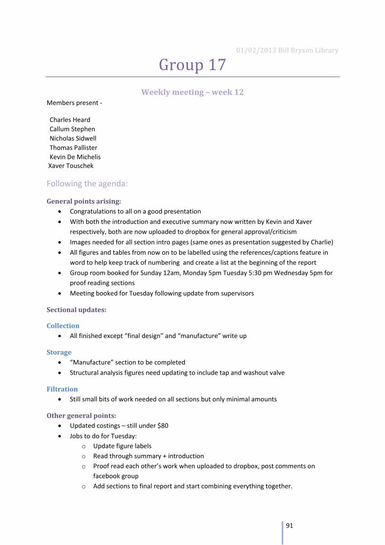
91
01/02/2013 Bill Bryson Library
Group 17
Weekly meeting – week 12 Members present -
Charles Heard
Callum Stephen
Nicholas Sidwell
Thomas Pallister
Kevin De Michelis Xaver Touschek
Following the agenda:
General points arising:
Congratulations to all on a good presentation
With both the introduction and executive summary now written by Kevin and Xaver
respectively, both are now uploaded to dropbox for general approval/criticism
Images needed for all section intro pages (same ones as presentation suggested by Charlie)
All figures and tables from now on to be labelled using the references/captions feature in
word to help keep track of numbering and create a list at the beginning of the report
Group room booked for Sunday 12am, Monday 5pm Tuesday 5:30 pm Wednesday 5pm for
proof reading sections
Meeting booked for Tuesday following update from supervisors
Sectional updates:
Collection
All finished except “final design” and “manufacture” write up
Storage
“Manufacture” section to be completed
Structural analysis figures need updating to include tap and washout valve
Filtration
Still small bits of work needed on all sections but only minimal amounts
Other general points:
Updated costings – still under $80
Jobs to do for Tuesday:
o Update figure labels
o Read through summary + introduction
o Proof read each other’s work when uploaded to dropbox, post comments on
facebook group
o Add sections to final report and start combining everything together.